

Page 1

Dell™ PowerEdge™
M1000e Systems
Configuration Guide
Guide de configuration
Konfigurationsanleitung
Guía de configuración
Page 2

Page 3

Dell™ PowerEdge™
M1000e Systems
Configuration Guide
Page 4

Notes, Notices, and Cautions
NOTE: A NOTE indicates important information that helps you make better use of
your computer.
NOTICE: A NOTICE indicates either potential damage to hardware or loss of data
and tells you how to avoid the problem.
CAUTION: A CAUTION indicates a potential for property damage, personal injury,
or death.
____________________
Information in this document is subject to change without notice.
© 2008 Dell Inc. All rights reserved.
Reproduction of these materials in any manner whatsoever without the written permission of Dell Inc.
is strictly forbidden.
Trademarks used in this text: Dell, the DELL logo, PowerEdge, and Dell OpenManage are trademarks
of Dell Inc.; Microsoft, Windows, and Active Directory are either trademarks or registered trademarks
of Microsoft Corporation in the United States and/or other countries.
Other trademarks and trade names may be used in this document to refer to either the entities claiming
the marks and names or their products. Dell Inc. disclaims any proprietary interest in trademarks and
trade names other than its own.
August 2008 P/N U003C Rev. A00
Page 5

Contents
1 About Your System . . . . . . . . . . . . . . . . . . 7
System Overview . . . . . . . . . . . . . . . . . . . . . 7
System Control Panel Features
LCD Module
. . . . . . . . . . . . . . . . . . . . . . . 11
LCD Module Menus
Back-Panel Features
Blades
. . . . . . . . . . . . . . . . . . . . . . . . . . 13
CMC Module
. . . . . . . . . . . . . . . . . . 13
. . . . . . . . . . . . . . . . . . . . . . . 16
CMC Daisy Chaining (Enclosure Stacking)
iKVM Switch Module
. . . . . . . . . . . . . . . . . . 19
. . . . . . . . . . . . . 10
. . . . . . . . . . . . . . . . 12
. . . . 17
2 Initial System Configuration . . . . . . . . . . 21
Before You Begin . . . . . . . . . . . . . . . . . . . . 21
Power Requirements
Network Information
Initial Setup Sequence
Configuring the CMC
Initial CMC Network Configuration
Logging in to the CMC Using the Web-Based
Interface
. . . . . . . . . . . . . . . . . . . . . . 25
Adding and Managing CMC Users
. . . . . . . . . . . . . . . . 21
. . . . . . . . . . . . . . . . 21
. . . . . . . . . . . . . . . . . 21
. . . . . . . . . . . . . . . . . . 22
. . . . . . . . 22
. . . . . . . . . 26
Contents 3
Page 6

Configuring iDRAC Networking Using the
Web-Based Interface
. . . . . . . . . . . . . . . 27
Setting the First Boot Device for Servers
Configuring and Managing Power
. . . . . . . . . 28
Installing or Updating the CMC Firmware
. . . . . 28
. . . . . 29
Configuring the Optional iKVM Switch Module
. . . . 31
Enabling iKVM Access to the Dell CMC
Console
Updating the iKVM Firmware
. . . . . . . . . . . . . . . . . . . . . . . 31
. . . . . . . . . . . . 31
Tiering the Avocent iKVM Switch From an
Analog KVM Switch
. . . . . . . . . . . . . . . . 32
Tiering the Avocent iKVM Switch From a
Digital KVM Switch
Viewing and Selecting Servers
FlexAddress
. . . . . . . . . . . . . . . . . . . . . . . 36
. . . . . . . . . . . . . . . . . 33
. . . . . . . . . . 34
3 Configuring the I/O Modules . . . . . . . . . . 37
Overview . . . . . . . . . . . . . . . . . . . . . . . . . 37
Before You Begin
Network Information
Switch Modules
Configuring a Switch Module Network Ethernet
Port Using the Web-Based Interface
Cisco SFS M7000e Infiniband Switch Module
PowerConnect M6220 Ethernet Switch
Module
Cisco Ethernet Switch
Brocade M4424 SAN I/O Module
. . . . . . . . . . . . . . . . . . . . 39
. . . . . . . . . . . . . . . . 39
. . . . . . . . . . . . . . . . . . . . . 39
. . . . . . . 39
. . . 40
. . . . . . . . . . . . . . . . . . . . . . . 42
. . . . . . . . . . . . . . . 43
. . . . . . . . . 45
4 Contents
Page 7

Pass-through Modules . . . . . . . . . . . . . . . . . 47
Ethernet Pass-through Module
Fibre Channel Pass-through Module
. . . . . . . . . . 47
. . . . . . . 49
Contents 5
Page 8

6 Contents
Page 9

About Your System
System Overview
Your system can include up to 16 half-height blades (server modules), eight
full-height blades, or a mixture of the two blade types (see Figure 1-1,
Figure 1-2, and Figure 1-3). To function as a system, a blade is inserted into a
enclosure (chassis) that supports power supplies, fan modules, a Chassis
Management Controller (CMC) module, and at least one I/O module for
external network connectivity. The power supplies, fans, CMC, optional
iKVM module, and I/O modules are shared resources of the blades in the
enclosure.
Configuration Guide 7
Page 10

Figure 1-1. Blade Numbering – Half-Height Blades
12345678
91011 1213141516
8 Configuration Guide
Page 11
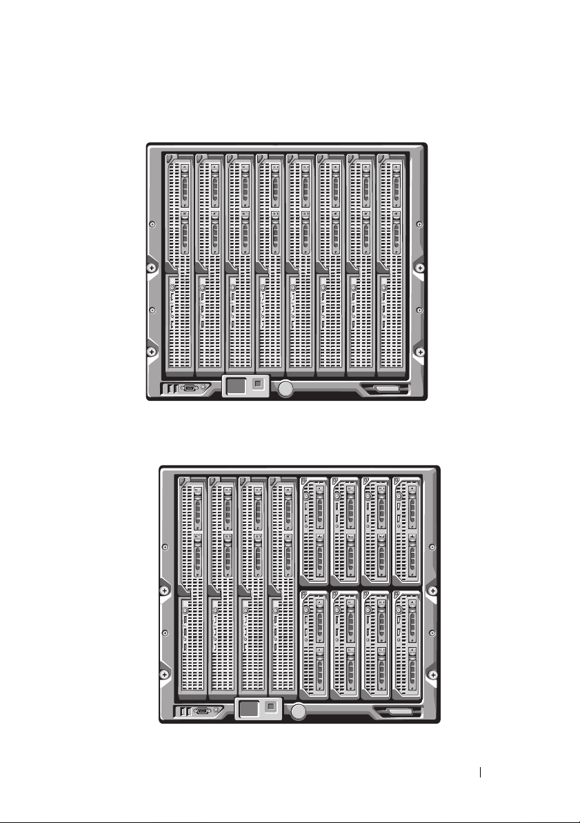
Figure 1-2. Blade Numbering - Full Height Blades
12345678
Figure 1-3. Blade Numbering - Mixed Full-Height and Half-Height Blades
12345678
13 14 15 16
Configuration Guide 9
Page 12
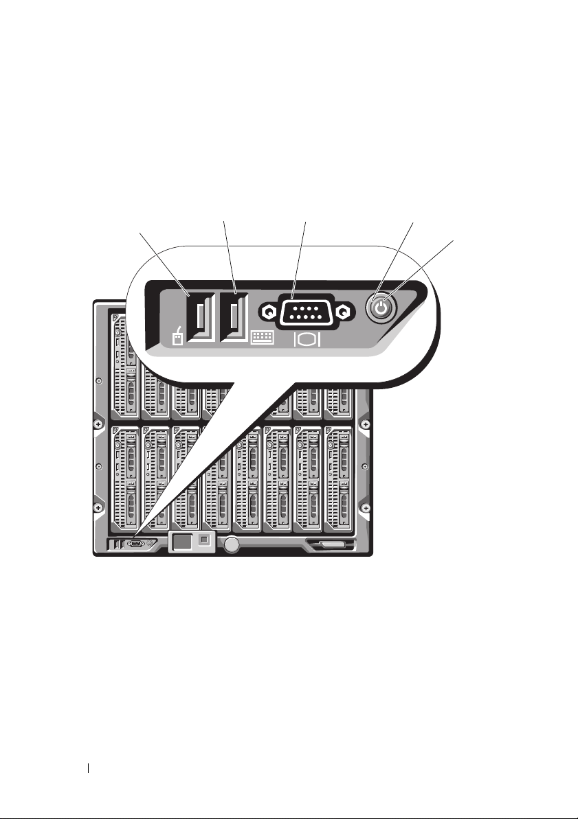
System Control Panel Features
Figure 1-4 shows the control panel features on the M1000e enclosure front
panel.
Figure 1-4. Control Panel Features
1
2
1 USB port (mouse only) 2 USB port (keyboard only)
3 video connector 4 system power button
5 system power indicator
3
4
5
NOTE: The USB and video ports are functional only if an optional iKVM module is
installed.
10 Configuration Guide
Page 13
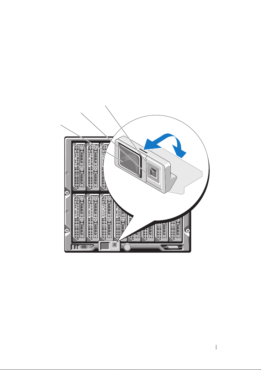
LCD Module
The LCD module provides an initial configuration/deployment wizard, as
well as access to infrastructure and blade information and error reporting. See
Figure 1-5.
Figure 1-5. LCD Module
3
2
1
1 LCD screen 2 scroll buttons (4)
3 selection ("check") button
Configuration Guide 11
Page 14

LCD Module Menus
Main Menu
The Main Menu options include links to the Server Menu, the Enclosure
Menu, and the LCD Setup Menu.
LCD Setup Menu
You can change the default language and startup screen for the LCD menu
screens using this menu.
Server Menu
From the Server Menu dialog box, you can highlight each blade in the
enclosure using the arrow keys, and view its status.
• A blade that is powered off or booting is designated by a gray rectangle. An
active blade is indicated by a green rectangle. If a blade has errors, this
condition is indicated by an amber rectangle.
• To select a blade, highlight it and press the center button. A dialog box
displays the iDRAC IP address of the blade and any errors present.
Enclosure Menu
The Enclosure Menu includes options for Module Status, Enclosure Status,
and IP Summary.
•In the
•In the
•The
Module Status
dialog box, you can highlight each component in the
enclosure and view its status.
– A module that is powered off or booting is designated by a gray
rectangle. An active module is indicated by a green rectangle. If a
module has errors, it will be indicated by an amber rectangle.
– If a module is selected, a dialog box displays the current status of the
module and any errors present.
Enclosure Status
dialog box, you can view the enclosure status, any
error conditions, and power consumption statistics.
IP Summary
screen shows IP information for the CMC(s), and the
iDRAC of each installed server.
12 Configuration Guide
Page 15
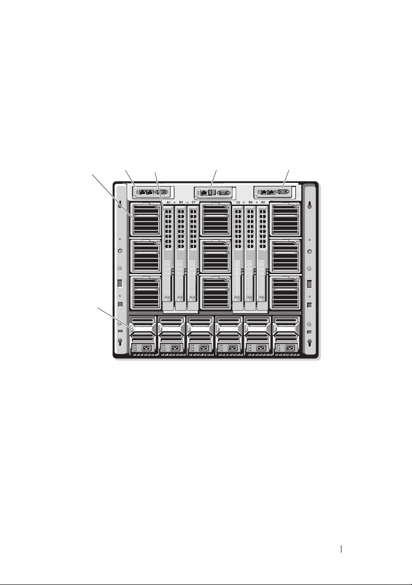
Back-Panel Features
The back of the M1000e enclosure supports six I/O modules, one or two
CMC modules, an optional iKVM module, nine fan modules, and six power
supply modules. Figure 1-6 shows a fully configured enclosure.
Figure 1-6. Back-Panel Features
2
1
6
1 fan modules (9) 2 primary CMC module
3 I/O modules (6) 4 optional iKVM module
5 secondary CMC module 6 power supplies (6)
3
4
5
Blades
Figure 1-7 shows the front panel features on the M600 and M605 blades.
Figure 1-8 shows the front panel features on the M905 and M805 blades.
Configuration Guide 13
Page 16

Figure 1-7. Front Panel Features - PowerEdge M600 and M605
1
6
5
4
3
2
1 blade handle release button 2 hard drives (2)
3 blade status/identification indicator 4 USB connectors (2)
5 blade power button 6 blade power indicator
14 Configuration Guide
Page 17
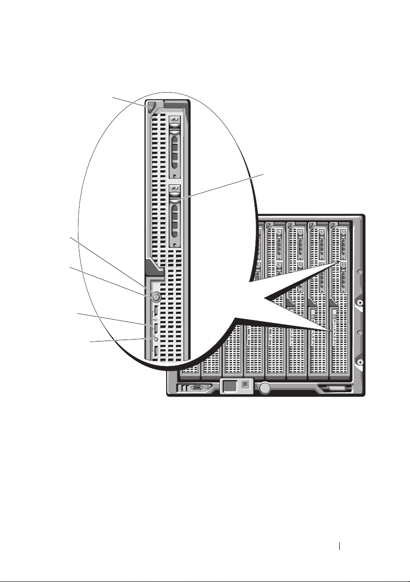
Figure 1-8. Front Panel Features - PowerEdge M905 and M805
1
2
6
5
4
3
1 blade handle release button 2 hard drives (2)
3 blade status/identification indicator 4 USB connectors (3)
5 blade power button 6 blade power indicator
Configuration Guide 15
Page 18
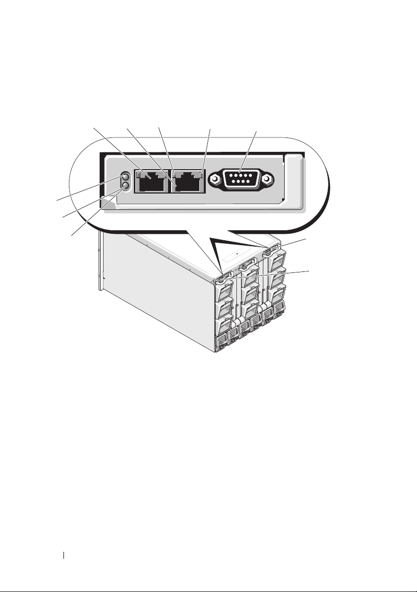
CMC Module
Figure 1-9. CMC Module Features
1
10
9
8
1 Ethernet connector Gb1 2 Ethernet connector STK (used for
3 link indicator (2) 4 activity indicator (2)
5 DB-9 serial connector for local
configuration
7 primary CMC (CMC 1) 8 amber fault indicator
9 blue status/identification indicator 10 power indicator
2
3
4
6 optional secondary CMC (CMC 2)
5
6
7
daisy-chaining CMCs in separate
enclosures)
The CMC provides multiple systems management functions for your
modular server, including the M1000e enclosure’s network and security
settings,
I/O module and iDRAC network settings, and
power redundancy and
power ceiling settings.
16 Configuration Guide
Page 19

CMC Daisy Chaining (Enclosure Stacking)
CMC daisy chaining can be utilized to minimize the number of network
connections required for chassis (enclosure) management, such that only one
or two network connections (depending on whether or not redundant CMCs
are installled) are needed for up to four M1000e enclosures.
Cabling Guidelines
Follow these guidelines to daisy chain CMC modules from enclosure to
enclosure:
• CMC Ethernet port "GB1" is the "Uplink" port. It will uplink to either the
management network, or to receive a cable from the CMC Ethernet port
labeled "STK" in the adjacent enclosure.
The CMC Ethernet port labeled "STK" is the "daisy-chain" port. It will
only
connect to CMC port GB1 on the adjacent enclosure. Do not connect
this cable directly to the management network.
• Up to 4 enclosures can be daisy-chained.
• Enclosures can be daisy-chained in both redundant and non-redundant
deployments:
– In a redundant CMC deployment, cable all CMC modules in the CMC
primary slots together. Cable all CMC modules in the CMC secondary
slots together. Do not connect the primary daisy chain with the
secondary daisy chain (do not “cross cable” the two sets of CMCs).
– In a non-redundant CMC, cable all CMC modules in the CMC
primary slots together.
Figure 1-10 shows four enclosures with redundant CMC modules installed.
Primary CMC port GB1 in the first enclosure connects to the management
network. Primary CMC port GB1 in the adjacent enclosure is "uplinked” into
the port labeled "STK" on the primary CMC in the enclosure above it. No
cable is required in port STK on the fourth enclosure in line. The same
cabling scheme is valid for the daisy chain of CMC modules in the secondary
slot of the enclosures.
Configuration Guide 17
Page 20

Figure 1-10. CMC Daisy-Chaining – Enclosure With Redundant CMC Modules
1
2
3
1 Management network segment 2 CMC1 – cable from connector
Gb1 to network
3 CMC2 – cable from connector
Gb1 to network
18 Configuration Guide
Page 21

iKVM Switch Module
The optional Avocent iKVM analogue switch module provides connections
for a keyboard, video (monitor), and mouse. It includes the following
features:
• Local iKVM access can be remotely disabled on a per blade basis, using the
blade’s iDRAC interface (access is enabled by default).
NOTE: By default (enabled), a console session to a given blade will be
available to both the iDRAC interface and a iKVM (user connected to a blade's
console via iDRAC and the iKVM will see the same video and be able to type
commands). The iDRAC will If this sharing is not desired, this can be disabled
via the iDRAC console interface.
• The following connectors:
– One VGA connector. The iKVM supports a video display resolution
range from 640x480 at 60Hz up to 1280x1024x65,000 colors
(noninterlaced) at 75Hz.
– Two USB ports for keyboard and mouse.
NOTE: The iKVM USB ports do not support storage devices.
– RJ-45 ACI port for tiering with Dell and Avocent analog KVM and
KVM over IP switches with ARI ports.
NOTE: Although the ACI port is an RJ-45 connector and uses Cat5 (or better)
cabling, it is not an Ethernet network interface port. It is only used for
connection to external KVM switches with Analog Rack Interface (ARI) ports,
and does not support native KVM over IP.
• The iKVM can also be accessed from the front of the enclosure, providing
front or rear panel KVM functionality, but not at the same time. For
enhanced security, front panel access can be disabled using the CMC’s
interface.
NOTE: Connecting a keyboard, video, and mouse to the enclosure front panel
will disable video output to the iKVM back panel port. It will not interrupt
iDRAC video and console redirection.
• You can use the iKVM to access the CMC using the Command-Line
Interface. For more information, see "Using the iKVM Module" in the
CMC
User’s Guide.
Configuration Guide 19
Page 22

Figure 1-11 shows the external features of the iKVM module.
Figure 1-11. Avocent iKVM Switch Module
2
1
1 identification indicator 2 status indicator
3 ACI port for tiering connection
only
5 video connector
NOTICE: Do not connect the ACI port to a LAN device such as a network
hub. Doing so may result in equipment damage.
34
4 USB connectors (2) for keyboard
5
and mouse
20 Configuration Guide
Page 23

Initial System Configuration
Before You Begin
Power Requirements
NOTICE: The enclosure power supplies must be connected to a Type B or
permanently-connected PDU, not directly to an electrical outlet. The power
supplies require a 200–240 V power source.
Network Information
If your network uses static addressing, you will need the IP address, subnet
mask, and gateway
Initial Setup Sequence
1
Unpack the enclosure and install it in a rack.
See the
information.
NOTICE: Do not power-on the blades (server modules) until you have configured
the switch modules, as described in "Configuring the I/O Modules" on page 37.
2
Connect power to the power supplies.
to configure the CMC and other modules in the enclosure.
Getting Started Guide
and
Rack Installation Guide
for more
NOTICE: The power supplies must be connected to a PDU, not directly to an
electrical outlet. The power supplies require a 200–240 V power source.
3
If an optional iKVM module is installed, connect the keyboard, video, and mouse to the enclosure control panel (see Figure 1-4) or to the iKVM module (see Figure 1-11).
NOTE: Connecting a keyboard, video, and mouse to the enclosure front panel
will disable video output to the iKVM back panel port.
Configuration Guide 21
Page 24

4
Press the power button on the enclosure control panel. See Figure 1-4.
5
Configure the CMC network settings.
The LCD Configuration Wizard allows you to quickly configure the CMC
and iDRAC management interfaces and on the network, so you can then
manage the enclosure remotely. See "Configuring the CMC Network
Settings Using the LCD Configuration Wizard" on page 23.
You can also use a management station and the RACADM CLI to
configure the CMC. See "Configuring the CMC Network Settings Using a
Management Station and CLI" on page 24.
6
Configure the IO modules at this time to allow proper network or storage management or paths. See "Configuring the I/O Modules" on page 37.
7
Once the Ethernet and Fibre Channel switches are configured and able to pass traffic, you can then power on your server blades. This will allow time for the Ethernet switch to boot and allow PXI \ UNDI traffic for all blade modules.
Configuring the CMC
Initial CMC Network Configuration
Connecting to the CMC Using a Network Connection and the Default IP Address, or a User-Defined IP Address
The CMC is preset for DHCP. To use a static IP address you must toggle the
CMC setting from DHCP to a static address by either running the LCD
Configuration Wizard, or by using a management station and CLI
commands.
If toggled to use a static address, the CMC IP address will default to the
standard IP address settings of 192.168.0.120, 255.255.255.0, and gateway of
192.168.0.1. You can change this address to an IP address of your choosing.
See "Configuring the CMC Network Settings Using the LCD Configuration
Wizard" on page 23 for initial configuration instructions. If you prefer to use a
management station and CLI, see "Configuring the CMC Network Settings
Using a Management Station and CLI" on page 24.
22 Configuration Guide
Page 25

Configuring the CMC Network Settings Using the LCD Configuration Wizard
When you first start up your system, the screen on the LCD module will
direct you to configure the CMC network settings.
NOTE: The option to configure the server using the LCD Configuration Wizard is
only available until the CMC is connected to the network or the default password is
changed. Once the CMC is accessible from the network, the LCD panel cannot be
used to reconfigure the CMC. Thereafter, use the RACADM CLI or the web-based
GUI to change the CMC settings.
Table 2-1 lists the keys that you use to view or change information on the
LCD module screens.
Table 2-1. LCD Module Screen Navigation Keys
Keys Action
Left and right arrows Move between screens.
Up arrow or down arrow Move to the previous or next option on a screen.
Center button Select and save an item and move to the next
screen.
Choose a language from the options presented in the dialog box.
1
2
Start the LCD Configuration Wizard.
3
Configure the CMC network settings for your network environment
NOTE: The CMC external management network mode is set by default to
DHCP. To use a static IP address, you must change the setting using the LCD
Configuration Wizard.
– Network speed
– Duplex mode
– Network mode (DHCP or static)
– Static IP address, subnet mask, and gateway values (if static mode was
selected)
– DNS setting, including a registered CMC name, (if DHCP mode was
selected)
Configuration Guide 23
Page 26

4
If desired, configure the iDRAC network setting for DHCP mode.
NOTE: You cannot set a static IP address for the iDRAC using the LCD
Configuration Wizard. See "Configuring iDRAC Networking Using the WebBased Interface" on page 27.
5
Review the settings on the
Network Summary
screen.
– If the settings are correct, press the center button to close the
configuration wizard and return to the
Main Menu
.
– If the settings are not correct, use the left arrow key to return to the
screen for that setting and correct it.
After you complete the LCD Configuration Wizard, y
ou can access the CMC
on the network using the Web-based CMC interface or text-based interfaces
such as a serial console, Telnet, or SSH.
Note that if you intend to use static addresses rather than DHCP to access
the iDRACs, you must configure them using the CMC Web-based interface
or CLI.
Configuring the CMC Network Settings Using a Management Station and CLI
The LCD Configuration Wizard is the quickest way to initially configure the
CMC network settings. However, you can also use a management station and
and a local connection to access the CMC. There are two ways to create a
local connection to the CMC:
• The CMC Console via the optional iKVM. Press <Print Screen> and
select blade number 17. Blade number 17 is a direct local connection to
the CMC.
• Serial connection using a null modem cable (115200 bps, 8 Data bits, no
parity, 1 stop bit, and no flow control).
Once you have established a connection to the CMC, you can complete the
initial CMC network configuration:
1
Log into the CMC.
The default user name is
root
and the default password is
calvin
.
2
Ty p e
getniccfg
and press <Enter> to view the current CMC network
parameters.
24 Configuration Guide
Page 27

3
Configure the CMC network settings:
–
To set a static IP address
setniccfg -s<IP address><network mask><gateway>
and press <Enter>.
Use the appropriate settings for your network.
, type
To configure the CMC to obtain an IP address using DHCP
–
setniccfg -d
and press <Enter>.
4
To activate the new network settings, type
racadm racreset
and press <Enter>.
Logging in to the CMC Using the Web-Based Interface
1
Open a supported Web browser window.
For more information, see "Supported Web Browsers" in the CMC
Guide
.
2
Login to the CMC.
If the CMC is accessed using a specific IP address
–
URL In the
https://<CMC
The default IP address for the CMC is 192.168.0.120. If the default
HTTPS port number (port 443) has been changed, type:
https://<CMC
where
number
Address
<IP address
is the HTTPS port number.
field, and then press <Enter>:
IP address>
IP address>:<port number
> is the IP address for the CMC and
, type the following
, type
User’s
>
port
If you access the CMC using a registered DNS name,
–
name:
https://<CMC name
By default, the CMC name on the DNS server is
.
tag>
>
Configuration Guide 25
type the CMC’s
cmc-<service
Page 28

3
The CMC
NOTE: The default CMC user name is root, and the password is calvin. The
root account is the default administrative account that ships with the CMC. For
added security, you should change the default password of the root account during
initial setup.
NOTE: The CMC does not support extended ASCII characters, such as ß, å, é, ü, or
other characters used primarily in non-English languages.
NOTE: You cannot log in to the Web-based interface with different user names in
multiple browser windows on a single workstation.
Login
page appears.
You can log in as either a CMC user or as a Microsoft® Active Directory®
user.
4
In the
Username
– CMC user name:
– Active Directory user name:
<domain>/<user name>
NOTE: This field is case sensitive.
5
In the
Passwo rd
field, type your user name:
<user name>
<domain>\<user name>
or
<user>@<domain>
,
.
field, type your CMC user password or Active Directory
user password.
NOTE: This field is case sensitive.
Adding and Managing CMC Users
From the Users and User Configuration pages in the Web-based interface,
you can view information about CMC users, add a new user, and change
settings for an existing user.
NOTE: For added security, Dell strongly recommends that you change the default
password of the root (User 1) account. The root account is the default
administrative account that ships with the CMC. To change the default password for
the root account, click User ID 1 to open the User Configuration page. Help for that
page is available through the Help link at the top right corner of the page.
NOTE: You must have User Configuration Administrator privileges to perform the
following steps.
1
Log in to the Web-based interface. See "Logging in to the CMC Using the Web-Based Interface" on page 25.
2
Select
Chassis
in the system tree.
26 Configuration Guide
Page 29

3
Click the
Users
Network/Security
tab, and then click the
Users
sub-tab. The
page appears, listing each user’s user ID, login state, user name, and
CMC privilege, including those of the root user. User IDs available for
configuration will have no user information displayed.
4
Click an available user ID number. The
To refresh the contents of the
contents of the
5
Select general settings for the users.
Users
age, click
Users
Print
User Configuration
page, click
Refresh
.
page displays.
. To print the
For details on user groups and privileges, see "Adding and Configuring
Users" in the CMC
6
Assign the user to a CMC user group.
User’s Guide
.
When you select a user privilege setting from the CMC Group drop-down
menu, the enabled privileges (shown as checked boxes in the list) display
according to the pre-defined settings for that group.
You can customize the privileges settings for the user by checking or unchecking boxes. After you have selected a CMC Group or made Custom
user privilege selections, click
Apply Changes
to keep the settings.
Configuring iDRAC Networking Using the Web-Based Interface
Follow this procedure if you did not configure the iDRAC in the LCD
Configuration Wizard.
NOTE: If you did not configure the iDRA using the LCD COnfiguration Wizard, the
iDRAC will be disabled until you configure it using the Web-based interface
NOTE: You must have Chassis Configuration Administrator privileges to set up
iDRAC network settings from the CMC.
NOTE: The default CMC user is root and the default password is calvin.
1
Log in to the Web-based interface. See "Logging in to the CMC Using the Web-Based Interface" on page 25.
2
Click the plus (+) symbol next to
Servers
.
3
Click
Setup →
4
Enable the LAN for the iDRAC on the server by checking the checkbox
Deploy
.
next to the server beneath the
Chassis
Enable Lan
in the left column, then click
heading.
Configuration Guide 27
Page 30

5
Enable or disable IPMI over LAN by checking the or unchecking the
checkbox next to the server beneath the
6
Enable or disable DHCP for the iDRAC by checking or unchecking the
checkbox next to the server under the
7
If DHCP is disabled, enter the static IP address, netmask, and default gateway for the iDRAC.
8
Click
Apply
at the bottom of the page.
Enable IPMI over LAN
DHCP Enabled
heading.
heading.
Setting the First Boot Device for Servers
The First Boot Device page allows you to specify the boot device for each
blade. You can set the default boot device and you can also set a one-time
boot device so that you can boot a special image to perform tasks such as
running diagnostics or reinstalling an operating system.
To set the first boot device for some or all servers in the chassis:
1
Log in to the CMC Web-based interface.
2
Click
Servers
in the system tree and then click
Device
. A list of servers is displayed, one per row.
3
Select the boot device you want to use for each server from the list box.
4
If you want the server to boot from the selected device every time it boots,
unselect the
If you want the server to boot from the selected device only on the next
boot cycle, select the
Boot Once
Boot Once
checkbox for the server.
checkbox for the server.
Setup →
Deploy First Boot
5
Click
Apply
.
Configuring and Managing Power
You can use the Web-based and RACADM interfaces to manage and
configure power controls on the CMC, as outlined in the following sections.
For detailed information on the various power management options, see
"Power Management" in the CMC User’s Guide.
Configuring Power Budget and Redundancy
The CMC’s power management service optimizes power consumption for the
entire chassis (the chassis, servers, I/O modules, iKVM, CMC, and PSUs) and
re-allocates power to different modules based on the demand.
28 Configuration Guide
Page 31

NOTE: To perform power management actions, you must have Chassis Control
Administrator privileges.
1
Log in to the CMC Web-based interface.
2
Select
3
Click the
Chassis
in the system tree.
Power Management
tab. The
Power Budget Status
page
displays.
4
Click the
Configuration
sub-tab. The
Budget/Redundancy Configuration
page displays.
5
Configure the power budget and redundancy settings based on the components in the enclosure and your needs.
6
Click
Apply
to save your changes.
Installing or Updating the CMC Firmware
NOTE: During updates of CMC or iDRAC firmware on a server, some or all of the fan
units in the chassis will spin at 100%. This is normal.
Updating Firmware in a Redundant CMC Configuration
NOTE: In redundant CMC configuration, care must be taken to update CMC
firmware on both modules. Failure to do so may cause unexpected behavior during
a CMC failover or failback. Use the following procedure for redundant CMC
deployments:
1
Locate the secondary or standby CMC by using the RACADM
command, or by using the
interface
.
Visually, the status indicator will be solid blue on the primary or
Chassis Summary
page in the Web-based
active CMC module and off on the standby or secondary CMC (see
Figure 1-9).
2
Update the firmware on the standby CMC first. See "Updating the CMC Firmware Using the Web-based Interface" on page 30 or "Updating the CMC Firmware Using RACADM" on page 31.
3
Verify that the secondary or standby CMC’s firmware is at the requested
level with the
4
After the standby CMC has rebooted, update the firmware on the active or
getsysinfo
command or through the Web-based interface.
primary CMC. Please allow 10 minutes for the standby CMC to boot.
See "Updating the CMC Firmware Using the Web-based Interface" on
page 30 or "Updating the CMC Firmware Using RACADM" on page 31.
getsysinfo
Configuration Guide 29
Page 32

5
Verify that the active or primary CMC firmware is at the requested level
using the
6
Once both CMCs are updated to the same firmware revision, use the
cmcchangeover
Downloading the CMC Firmware
getsysinfo
command or through the Web-based interface.
command to reset the CMC in the left slot as primary.
Before beginning the firmware update, download the latest firmware version
from the Dell Support website, and save it to your local system.
The following software components are included with your CMC firmware
package:
• Compiled CMC firmware code and data
• Web-based interface, JPEG, and other user interface data files
• Default configuration files
Use the Firmware Update page to update the CMC firmware to the latest
revision. When you run the firmware update, the update retains the current
CMC settings.
NOTE: The firmware update, by default, will retain the current CMC settings.
During the update process, you have the option to reset the CMC configuration
settings back to the factory default settings.
Updating the CMC Firmware Using the Web-based Interface
1
Log in to the Web-based interface. See "Logging in to the CMC Using the Web-Based Interface" on page 25.
2
Click
Chassis
3
Click the
4
On the
Firmware Update
5
In the
network where the firmware image file resides, or click
in the system tree.
Update
tab. The
Updatable Components
Updatable Components
page appears.
page, click the CMC name. The
page appears.
Va l u e
field, type the path on your management station or shared
Browse
to navigate
to the file location.
NOTE: The default CMC firmware image name is firmimg.cmc and the
filename should not be changed. Care must be taken to keep different
firmware revisions separated as the file name will always be the same.
6
Click
Update
. A dialog box appears asking you to confirm the action.
30 Configuration Guide
Page 33

7
Click
Yes
to continue. The firmware transfer process will begin and the
status will display the message "Firmware Update in Progress". Once the
CMC update is complete, the CMC will be reset. Once the reset is
complete, you will need to refresh the User Interface page to then log in
again.
Updating the CMC Firmware Using RACADM
1
Open a CMC command line console and log in.
2
Ty p e :
racadm fwupdate -g -u -a <TFTP server IP address>
-d <filepath> -m <cmc-active|cmc-standby>
See the latest Dell Chassis Management Controller User's Guide at
support.dell.com for complete instructions on how to configure and operate
the CMC module.
Configuring the Optional iKVM Switch Module
Enabling iKVM Access to the Dell CMC Console
Enabling access to the CMC allows you to access the CMC directly and
securely through the iKVM’s CMC Console option. To enable the CMC
Console using the Web-based interface:
Log in to the CMC Web-based interface.
1
2
Select iKVM in the system tree. The
3
Click the
4
Select
5
Click
Setup
tab. The
Allow access to CMC CLI from iKVM
Apply
to save the setting.
iKVM Configuration
iKVM Status
page displays.
.
page displays.
Updating the iKVM Firmware
NOTE: The iKVM resets and becomes temporarily unavailable after the firmware
has been uploaded successfully.
1
Log in to the CMC’s Web-based interface. See "Logging in to the CMC Using the Web-Based Interface" on page 25.
2
Select
Chassis
in the system tree.
Configuration Guide 31
Page 34

3
Click the
4
Click the iKVM name. The
5
In the
network where the firmware image file resides, or click
Update
tab. The
Va l u e
field, type the path on your management station or shared
Updatable Components
Firmware Update
page appears.
page appears.
Browse
to navigate
to the file location.
NOTE: The default iKVM firmware image name is ikvm.bin. However, the
iKVM firmware image name can be renamed. If you are unable to locate
ikvm.bin, determine whether another user has renamed the file.
6
Click
7
Click
Update
Yes
. A dialog box appears asking you to confirm the action.
to continue.
When the update is complete, the iKVM resets.
Tiering the Avocent iKVM Switch From an Analog KVM Switch
The Avocent iKVM switch can be tiered from analog KVM switches such as
the Dell 2160AS and 180AS, as well as many Avocent analog KVM switches.
Many switches may be tiered without the need for a Server Interface Pod
(SIP) (see Table 2-2).
Table 2-2. Cabling Requirements for External Analog KVM Switches
Switch Tiering Cabling Requirements
Dell PowerConnect 180AS, 2160AS
Avocent Autoview 1400, 1500, 2000,
2020, 2030, Ax000R
Avocent Autoview 200, 400, 416, 424
Avocent Outlook 140ES, 180ES,
160ES
Seamless tiering using ACI port and
Cat 5 cable
Avocent USB SIP (DSRIQ-USB)
required with Cat 5 cable
Before connecting the iKVM switch to a supported analog switch, you must
set the iKVM switch to display in slot order, and set the Screen Delay Time to
1 or more seconds:
1
Press <Print Screen> to launch the iKVM Switch OSCAR.
2
Click
3
Setup → Menu
Select
Slot
to display servers numerically by slot number.
. The
Menu
dialog box appears.
32 Configuration Guide
Page 35

4
Enter a screen delay time of at least 1 second.
5
Click OK.
Setting the Screen Delay time to 1 second allows you to soft switch to a server
without launching OSCAR.
NOTE: Soft switching allows you to switch servers using a hot key sequence. You
can soft switch to a server by pressing <Print Screen> and then typing the first few
characters of its name or number. If you have a Delay Time set and you press the
key sequences before that time has elapsed, OSCAR will not display.
To connect the Avocent iKVM switch to a supported analog switch:
1
If the switch does not require a SIP to connect to the iKVM (see Table 2-2)
,
connect a Cat5 (or newer) cable to the RJ-45 ACI port on the iKVM
module. See Figure 1-11.
Connect the other end of this cable to the ARI port on the external switch.
If the analog switch requires a SIP (see Table 2-2)
dongle
or to the iKVM, then connect a Cat5 (or newer) cable to the
, connect a Avocent USB
SIP
.
Connect the other end of this cable to the ARI port on the external switch.
2
Connect both the analog switch and the system to an appropriate power source.
3
Power up the system.
4
Power up the
NOTE: If the external analog switch is powered up before the system, it may result
in only one blade displaying in the analog switch OSCAR, instead of 16. If this
behavior occurs, shut down and restart the switch so the entire complement of
blades is recognized.
NOTE: In addition to the steps outlined above, some external analog switches may
require you to perform additional steps to ensure that the iKVM switch blades
appear in the external analog switch OSCAR. See the external analog switch
documentation for additional information.
external
analog switch.
Tiering the Avocent iKVM Switch From a Digital KVM Switch
The iKVM module may also be tiered from a digital KVM switch such as the
Dell 2161DS-2 or 4161DS, or a supported Avocent digital KVM switch. Many
switches may be tiered without the need for a SIP (see Table 2-3).
Configuration Guide 33
Page 36

Table 2-3. Cabling Requirements for External Digital KVM Switches
Switch Tiering Requirements
Dell PowerConnect 2161DS-2,
4161DS
Avocent DSR 800, x16x, x010,
x031, x030, x035,102x (except
1024)
Avocent DSR 1024 Avocent USB SIP (DSRIQ-USB)
Seamless tiering using ACI port
and Cat 5 cable
required with Cat 5 cable
To tier the iKVM module from a Dell 2161DS, 180AS, or 2160AS console
switch:
•
If the switch does not require a SIP to connect to the iKVM (see
Table 2-3),
connect a Cat5 (or newer) cable to the RJ-45 ACI port on the iKVM
module. See Figure 1-11.
Connect the other end of this cable to the ARI port on the external switch.
•
If the switch requires a USB SIP (see Table 2-2)
SIP
to the iKVM, then connect a a Cat5 (or newer) cable to the
, connect an Avocent USB
SIP
.
Connect the other end of this cable to the ARI port on the external switch.
Once the KVM switch is connected, the server modules appear in OSCAR.
NOTE: When the local system is set up, you must also resynchronize the server list
from the Remote Console Switch software in order to see the list of blades. See
""Resynchronizing the Server List at the Remote Client Workstation" on page 35."
Viewing and Selecting Servers
Use the OSCAR Main dialog box to view, configure, and manage servers in
the M1000e enclosure through the iKVM. You can view the servers by name
or by slot. The slot number is the chassis slot number the server occupies. The
Slot column indicates the slot number in which a server is installed.
NOTE: Server names and slot numbers are assigned by the CMC.
NOTE: If you have enabled access to the CMC though the iKVM, an additional
option, Dell CMC Console, is displayed. To enable this feature, see "Enabling iKVM
Access to the Dell CMC Console" on page 31.
34 Configuration Guide
Page 37

To access the Main dialog box:
Press <Print Screen> to launch the OSCAR interface. The
Main dialog box
appears.
or
If a password has been assigned, the Password dialog box appears. Type your
password and click OK. The
Resynchronizing the Server List at the Remote Client Workstation
Main dialog box appears.
Once the iKVM module is connected, the blades appear in OSCAR. You now
need to resynchronize the servers on any remote workstation to ensure that
the blades are available to any remote users connected to the console switch
through the Remote Console Switch software.
NOTE: This procedure only resynchronizes one remote client workstation. With
multiple client workstations, save the resynchronized local database and load it into
the other client workstations to ensure consistency.
To resynchronize the server listing:
Click
Resync
in the
Server
1
category of the Management Panel (MP).
The Resync Wizard launches.
2
Click
Next
.
A warning message displays indicating that the database will be updated to
match the current configuration of the console switch. Your current local
database names will be overridden with the switch names. To include
unpowered SIPs in the resynchronization, click to enable the
Offline SIPs
checkbox.
Include
3
Click
Next
.
A
Polling Remote Console Switch
message box appears with a progress
bar indicating that the switch information is being retrieved.
4
If no changes were detected in the appliance, a completion dialog box appears with this information.
If server changes were detected, then the
Next
will be displayed. Click
to update the database.
Detected Changes
Configuration Guide 35
dialog box
Page 38

5
If a cascade switch was detected, the
dialog box appears. Select the type of switch connected to the appliance
from the drop-down list. If the type you are looking for is not available, you
can add it by clicking
6
Click
Next
. The completion dialog box appears.
Add
.
Enter Cascade Switch Information
FlexAddress
FlexAddress allows you to replace the factory-assigned World Wide
Name/Media Access Control (WWN/MAC) ID with a WWN/MAC ID that
is persistent and mapped to a particular chassis slot. If you purchase
FlexAddress with your chassis, it will be installed and active when you power
up your system. If you purchase FlexAddress at a later date, you must install
the SD feature card using the instructions in the CMC Secure Digital (SD)
Card Technical Specification document. See support.dell.com for this
document.
For complete information on using the FlexAddress feature, click the Help
link in the CMC Web interface, or review the "Using FlexAddress" chapter of
the CMC User’s Guide.
36 Configuration Guide
Page 39

Configuring the I/O Modules
Overview
The M1000e enclosure
between combinations of Ethernet and Fibre Channel modules. (Additional
fabrics including Infiniband will be supported in the future.) You can install up
to six hot-swappable I/O modules in the enclosure, including Fibre Channel
switches, Fibre Channel pass-throughs, Ethernet switches, and Ethernet passthrough modules
Figure 3-1. I/O Module Bay Numbering
supports three redundant I/O fabrics, selectable
. Figure 3-1 shows the numbering of the I/O bays.
A1 B1 C1
C2 B2 A2
2
Configuration Guide 37
Page 40

Fabric A
Fabric A is a redundant Gb Ethernet fabric, supporting I/O module slots A1
and A2. The integrated Ethernet controllers in each blade dictate Fabric A as
an Ethernet-only fabric.
NOTICE: Modules designed for Fabric B or Fabric C cannot be installed in slots A1
or A2. However, modules designed for Fabric A may also be installed in Fabric B and
Fabric C slots.
Fabric B
Fabric B is a 1 to 10 Gb/sec dual port, quad-lane redundant fabric, supporting
I/O module slots B1 and B2. Fabric B currently supports Gb Ethernet,
Infiniband, and Fibre Channel modules. Additional fabric types including
10 Gb Ethernet will be supported in the future.
To communicate with an I/O module in the Fabric B slots, a blade must have
a matching mezzanine card installed in a Fabric B mezzanine card location.
Modules designed for Fabric A may also be installed in the Fabric B slots.
Fabric C
Fabric C is a 1 to 10 Gb/sec dual port, quad-lane redundant fabric, supporting
I/O module slots C1 and C2. Fabric C currently supports Gb Ethernet,
Infiniband, and Fibre Channel modules. Additional fabric types including
10 Gb Ethernet will be supported in the future.
To communicate with an I/O module in the Fabric C slots, a blade must have
a matching mezzanine card installed in a Fabric C mezzanine card location.
Modules designed for Fabric A may also be installed in the Fabric C slots.
See your Hardware Owner’s Manual for more information about I/O module
installation guidelines.
38 Configuration Guide
Page 41

Before You Begin
Network Information
You can configure your I/O switch modules using the CMC, as outlined in
"Configuring a Switch Module Network Ethernet Port Using the Web-Based
Interface
through the CMC CLI via serial console redirection, direct access to the I/O
module’s serial port (if supported), or using the I/O module’s default IP address
(if supported).
" on page 39
(the default IP address for the CMC is 192.168.0.120),
Switch Modules
Configuring a Switch Module Network Ethernet Port Using the Web-Based Interface
You can use the CMC Web-based interface to configure an I/O module’s
Ethernet port.
NOTE: Use this procedure to configure the switch’s out-of-band Ethernet port. The
switch’s in-band management IP address is configured through the switch’s
external ports. These two IP addresses must be different, and on different
networks.
NOTE: To change settings on the I/O module configuration page, you must have
Fabric Administrator privileges for the particular Fabric in which the module is
installed.
NOTE: The network IP address set on the I/O module by the CMC is not saved to a
configuration file. To save the IP address configuration permanently, use the
connect switch-n RACADM command, or use a direct interface to the I/O
module GUI.
NOTE: Do not attempt to configure I/O module network settings for Ethernet
passthrough or Infiniband switches.
1
Log in to the CMC’s Web-based interface. See "Logging in to the CMC Using the Web-Based Interface" on page 25.
2
Select
3
Select the
page appears.
I/O Modules
Setup
in the
tab. The
Chassis
Configuring I/O Modules Network Settings
menu in the system tree.
Configuration Guide 39
Page 42

4
Configure the switch for integration into your network.
–Select
– If your network uses static IP addressing, enter an IP address, subnet
5
When you have finished, click
6
Click the
After all I/O modules have been configured and connected, the enclosure’s
blades can be inserted and booted with full network communication.
DHCP Mode Enabled
assign IP addresses.
mask and gateway.
Deploy
sub-tab.
if your network uses a DHCP server to
Apply
.
Cisco SFS M7000e Infiniband Switch Module
The Cisco SFS 7000e Infiniband switch module includes 24 4x DDR
Infiniband ports. Eight ports are external uplink ports, and 16 internal ports
provide connectivity to the blades in the enclosure. This switch module is
hot-pluggable and may be installed in Fabric B or Fabric C. See Figure 3-2.
40 Configuration Guide
Page 43

Figure 3-2. Cisco SFS M7000e Infiniband Switch Module Features
1
2
3
4
1 Infiniband ports (8) 2 port status indicator (8)
3 diagnostic status indicator 4 power indicator
Configuration Guide 41
Page 44

PowerConnect M6220 Ethernet Switch Module
The PowerConnect M6220 Ethernet switch module includes four external
10/100/1000 Mbps Ethernet connectors and one USB type A form factor serial
connector. See Figure 3-3.
Figure 3-3. PowerConnect M6220 Ethernet Switch Module Features
1
2
3
1 optional module (2) (dual 10 Gb
Ethernet uplink module shown)
3 serial connector (USB type-A form
factor)
5 status/identification indicator
42 Configuration Guide
4
5
2 standard 10/100/1000 Mb Ethernet
connectors (4)
4 power indicator
Page 45

Two option bays support the following three module options:
• A resilient stacking module with 2 x 24 Gb stacking ports
• A 10 Gb Ethernet module with two 10 Gb optical XFP connectors
• 10 Gb Ethernet module with two copper CX4 uplinks
Cisco Ethernet Switch
Your system supports three Cisco Catalyst Blade Switch (CBS) versions:
• The Cisco 3130G switch includes four
ports and two stacking ports.
• The Cisco CBS 3130X switch includes four
uplink ports,
• The Cisco CBS 3032 switch includes four
uplink ports.
The two option bays support the following module options:
• Cisco X2 10 Gb transceiver modules (CBS 3130X only)
• Cisco TwinGig converter modules
two 10 Gb uplink ports,
10/100/1000 Mb Ethernet uplink
10/100/1000 Mb Ethernet
and two stacking ports.
10/100/1000 Mb Ethernet
Configuration Guide 43
Page 46

Figure 3-4. Cisco Ethernet Switch Module Features
1
2
3
4
5
6
7
8
1 stacking port connectors (not
enabled in CBS 3032)
3 option bays (2) 4 Cisco status indicators
5 mode button 6 console port for switch
7 power indicator 8 status/identification indicator
2 10/100/1000 Mb Ethernet
connectors (4)
management
For additional information about the Cisco CBS Ethernet switch modules,
see the documentation that shipped with the module.
44 Configuration Guide
Page 47

Brocade M4424 SAN I/O Module
The Brocade M4424 SAN I/O module includes eight external autosensing
Fibre Channel ports (four ports are enabled in the standard configuration and
four additional ports may be enabled as an optional upgrade), 16 internal
ports, and one serial port with an RJ-45 connector. The external Fibre
Channel ports operate at 1 Gb/sec, 2 Gb/sec, or 4 Gb/sec. The Fibre Channel
switch module is hot-pluggable, and may be installed in Fabric B or Fabric C.
NOTE: The Fibre Channel switch module includes Short Wave Small Form Factor
Pluggable (SFP) optical transceivers. To ensure proper functionality, use only SFPs
provided with this module.
Configuration Guide 45
Page 48

Figure 3-5. Brocade M4424 SAN I/O Module Features
1
2
3
4
5
6
1 Fibre Channel port (8) 2 Fibre Channel port status
indicator (8)
3 Fibre Channel port speed
indicator (8)
5 module status indicator 6 power indicator
7 status/identification indicator
4 serial port (RJ-45 connector)
46 Configuration Guide
7
Page 49

Pass-through Modules
Ethernet Pass-through Module
The Ethernet pass-through module supports 10/100/1000 Mb connections,
and provides a direct connection between the optional internal Ethernet
mezzanine card in the blade or the integrated LOMs in the blade, and an
external Ethernet device (see Figure 3-6). The Ethernet pass-through
modules are hot-pluggable and may be installed in any of the three fabrics.
NOTE: No configuration is required for this module.
Configuration Guide 47
Page 50

Figure 3-6. Ethernet Pass-through Module Features
2
1
3
11
4
5
1 activity indicator (16) 2 link indicator (16)
3 RJ45 Ethernet connector (16) 4 power indicator
5 status/identification indicator
NOTE: Connectors on the Ethernet pass-through module correspond directly to the
blade number. For example, blade 5 is connected to port 5 on the Ethernet passthrough module. Integrated network adapter 1 will map to I/O slot A1. Integrated
network adapter 2 will map to I/O slot A2.
48 Configuration Guide
Page 51

Fibre Channel Pass-through Module
The Fibre Channel pass-through module provides a bypass connection
between a Fibre Channel mezzanine card in the blade and optical transceivers
for direct connection into a Fibre Channel switch or a storage array (see
Figure 3-7). The 16 pass-through ports on this module can negotiate speeds
of 1-, 2-, or 4-Gbps. The Fibre Channel pass-through modules are hotpluggable, and may be installed in Fabric B or Fabric C.
NOTE: No configuration is required for this module.
NOTE: To ensure proper functionality, use only the Short Wave Small Form Factor
Pluggable (SFP) transceivers provided with this module.
Configuration Guide 49
Page 52

Figure 3-7. Fibre Channel Pass-through Module Features
1
2
3
4
1 SFP Fibre Channel connector (16) 2 Fibre Channel green/amber
indicators (two per port)
3 power indicator 4 status/identification indicator
50 Configuration Guide
Page 53

Dell™ PowerEdge™
M1000e Systems
Guide de configuration
Page 54

Remarques, avis et précautions
REMARQUE : Une REMARQUE indique des informations importantes
qui peuvent vous aider à mieux utiliser votre ordinateur.
AVIS : Un AVIS vous avertit d'un risque de dommage matériel ou
de perte de données et vous indique comment éviter le problème.
PRÉCAUTION : Une PRÉCAUTION indique un risque potentiel
d'endommagement du matériel, de blessure corporelle ou de mort.
____________________
Les informations contenues dans ce document peuvent être modifiées sans préavis.
© 2008 Dell Inc. Tous droits réservés.
La reproduction de ce document de quelque manière que ce soit sans l'autorisation écrite de Dell Inc.
est strictement interdite.
Marques utilisées dans ce document : Dell, le logo DELL, PowerEdge et Dell OpenManage sont
des marques de Dell Inc. ; Microsoft, Windows, et Active Directory sont des marques ou des marques
déposées de Microsoft Corporation aux États-Unis et/ou dans d'autres pays.
Tous les autres noms de marques et marques commerciales utilisés dans ce document se rapportent
aux sociétés propriétaires de ces marques et de ces noms ou à leurs produits. Dell Inc. dénie tout intérêt
propriétaire vis-à-vis des marques et des noms de marque autres que les siens.
Août 2008 N/P U003C Rév. A00
Page 55

Table des matières
1 À propos du système . . . . . . . . . . . . . . . . 57
Présentation du système . . . . . . . . . . . . . . . . 57
Fonctionnalités du panneau de commande
du système
. . . . . . . . . . . . . . . . . . . . . . . . 60
Module LCD
Fonctionnalités du panneau arrière
Serveurs lames
Module CMC
. . . . . . . . . . . . . . . . . . . . . . . 61
Menus du module LCD
. . . . . . . . . . . . . . . . . . . . . 65
. . . . . . . . . . . . . . . . . . . . . . . 67
. . . . . . . . . . . . . . . 62
. . . . . . . . . . 64
Connexion en série
de modules CMC (empilage)
Module commutateur iKVM
. . . . . . . . . . . . 68
. . . . . . . . . . . . . . . 70
2 Configuration initiale du système . . . . . . 73
Avant de commencer . . . . . . . . . . . . . . . . . . 73
Configuration requise pour l'alimentation
Informations concernant le réseau
Procédure de configuration initiale
. . . . . . . . . . 73
. . . . . 73
. . . . . . . . 73
Table des matières 53
Page 56

Configuration du module CMC . . . . . . . . . . . . . 75
Configuration réseau initiale du module CMC
. . . 75
Connexion au module CMC
via l'interface Web
. . . . . . . . . . . . . . . . . 78
Ajout et gestion d'utilisateurs
sur le module CMC
. . . . . . . . . . . . . . . . . 80
Configuration des paramètres réseau
du module iDRAC via l'interface Web
. . . . . . . 81
Définition du premier périphérique
d'amorçage pour les serveurs
Configuration et gestion de l'alimentation
. . . . . . . . . . . 82
. . . . . 83
Installation ou mise à jour du micrologiciel
du module CMC
. . . . . . . . . . . . . . . . . . . 84
Configuration du module commutateur iKVM
en option
. . . . . . . . . . . . . . . . . . . . . . . . . 86
Activation de l'accès du module iKVM
à la console CMC Dell
Mise à jour du micrologiciel du module iKVM
. . . . . . . . . . . . . . . 86
. . . 87
Connexion du commutateur iKVM Avocent
à un commutateur KVM analogique
. . . . . . . . 88
Connexion du commutateur iKVM Avocent
à un commutateur KVM numérique
Affichage et sélection de serveurs
. . . . . . . . 90
. . . . . . . . 91
FlexAddress
54 Table des matières
. . . . . . . . . . . . . . . . . . . . . . . 93
Page 57

3 Configuration des modules d'E/S . . . . . . 95
Présentation . . . . . . . . . . . . . . . . . . . . . . . 95
Avant de commencer
. . . . . . . . . . . . . . . . . . 97
Informations concernant le réseau
Modules commutateurs
. . . . . . . . . . . . . . . . . 97
Configuration du port Ethernet réseau
d'un module commutateur à l'aide
de l'interface Web
. . . . . . . . . . . . . . . . . 97
Module commutateur SFS M7000e Infiniband
Module commutateur Ethernet
PowerConnect M6220
Commutateur Ethernet Cisco
. . . . . . . . . . . . . . . 100
. . . . . . . . . . . 101
Module d'E/S Brocade M4424
pour réseau SAN
Modules d'intercommunication
. . . . . . . . . . . . . . . . . . 103
. . . . . . . . . . . . 105
Module d'intercommunication Ethernet
Module d'intercommunication Fibre Channel
. . . . . . . . 97
. . . 98
. . . . . . 105
. . . 107
Table des matières 55
Page 58

56 Table des matières
Page 59

À propos du système
Présentation du système
Votre système peut comprendre jusqu'à 16 lames mi-hauteur (modules
serveurs), huit lames pleine hauteur ou un mélange des deux types de
lame (voir la Figure 1-1, la Figure 1-2 et la Figure 1-3). Pour fonctionner
de la même façon qu'un système, un serveur lame est installé dans un
châssis contenant des blocs d'alimentation, des modules de ventilation,
un module de gestion du châssis (Chassis Management Controller, CMC)
et au moins un module d'E/S pour la connectivité réseau externe. Les blocs
d'alimentation, les ventilateurs, les modules CMC, le module iKVM
en option et les modules d'E/S sont les ressources partagées des serveurs
lames installés dans le châssis.
Guide de configuration 57
Page 60

Figure 1-1. Numérotation des lames – Lames mi-hauteur
12345678
910111213141516
58 Guide de configuration
Page 61

Figure 1-2. Numérotation des lames – Lames pleine hauteur
12345678
Figure 1-3. Numérotation des lames – Mélange lames pleine hauteur et mi-hauteur
12345678
13 14 15 16
Guide de configuration 59
Page 62

Fonctionnalités du panneau de commande du système
La Figure 1-4 présente les caractéristiques du panneau de commande situé
sur le panneau avant du châssis M1000e.
Figure 1-4. Fonctionnalités du panneau de commande
1
2
1 Port USB (souris uniquement) 2 Port USB (clavier uniquement)
3 Connecteur vidéo 4 Bouton d'alimentation du système
5 Voyant d'alimentation du système
REMARQUE : Les ports USB et vidéo ne sont fonctionnels que si un module iKVM
en option est installé.
3
4
5
60 Guide de configuration
Page 63

Module LCD
Le module LCD inclut un assistant de configuration initiale et
de déploiement. Il permet d'accéder aux informations concernant
l'infrastructure et les serveurs lames, et fournit des fonctions de
signalement des erreurs. Reportez-vous à la Figure 1-5.
Figure 1-5. Module LCD
3
2
1
1 Écran LCD 2 Boutons de défilement (4)
3 Bouton de sélection («check»)
Guide de configuration 61
Page 64

Menus du module LCD
Menu principal
Les options de l'écran Main Menu (Menu principal) comprennent des
liens vers les écrans Server Menu (Menu Serveur), Enclosure Menu
(Menu Châssis) et LCD Setup Menu (Menu Configuration du
module LCD).
Écran LCD Setup Menu (Menu Configuration du module LCD)
Ce menu permet de modifier la langue et l'écran de démarrage par défaut
du module LCD.
Écran Server Menu (Menu Serveur)
La boîte de dialogue Server Menu (Menu Serveur) permet de sélectionner
chaque serveur lame du châssis à l'aide des touches fléchées et d'afficher
son état.
• Une lame hors tension ou en cours de démarrage est représentée par
un rectangle gris. Une lame active est représentée par un rectangle vert.
Si des erreurs se produisent sur une lame, celle-ci est représentée par
un rectangle orange.
• Pour sélectionner une lame, mettez-la en surbrillance et appuyez sur le
bouton central. Une boîte de dialogue affiche l'adresse IP correspondant
au module iDRAC de la lame, ainsi que les erreurs éventuellement
détectées.
62 Guide de configuration
Page 65

Écran Enclosure Menu (Menu Châssis)
L'écran Enclosure Menu (Menu Châssis) contient les options suivantes :
Module Status (État des modules), Enclosure Status (État du châssis)
et IP Summary (Récapitulatif IP).
• La boîte de dialogue
Module Status
(État des modules) permet de
sélectionner chaque composant du châssis et d'afficher son état.
– Un module hors tension ou en cours de démarrage est représenté par
un rectangle gris. Un module actif est représenté par un rectangle vert.
Si des erreurs se produisent sur un module, celui-ci est représenté par
un rectangle orange.
– Si un module est sélectionné, une boîte de dialogue affiche son état
actuel, ainsi que les erreurs éventuellement détectées.
• La boîte de dialogue
Enclosure Status
(État du châssis) permet d'afficher
l'état du châssis, les erreurs et les statistiques de consommation
énergétique.
• L'écran
IP Summary
(Récapitulatif IP) contient les informations IP du
ou des modules CMC et indique le module iDRAC de chaque serveur
installé.
Guide de configuration 63
Page 66

Fonctionnalités du panneau arrière
L'arrière du châssis M1000e peut accueillir six modules d'E/S, un ou deux
modules CMC, un module iKVM en option, neuf modules de ventilation et
six modules d'alimentation. La Figure 1-6 représente un châssis entièrement
équipé.
Figure 1-6. Fonctionnalités du panneau arrière
2
1
6
1 Modules de ventilation (9) 2 Module CMC principal
3 Modules d'E/S (6) 4 Module iKVM en option
5 Module CMC secondaire 6 Blocs d'alimentation (6)
3
4
5
64 Guide de configuration
Page 67

Serveurs lames
La Figure 1-7 présente les caractéristiques du panneau avant des serveurs
lames M600 et M605. La Figure 1-8 présente les caractéristiques du panneau
avant des serveurs lames M905 et M805.
Figure 1-7. Fonctionnalités du panneau avant – PowerEdge M600 et M605
1
2
6
5
4
3
1 Bouton d'éjection de la poignée 2 Disques durs (2)
3 Voyant d'état/d'identification
du serveur lame
5 Bouton d'alimentation du serveur
lame
4 Connecteurs USB (2)
6 Voyant d'alimentation du serveur
lame
Guide de configuration 65
Page 68

Figure 1-8. Fonctionnalités du panneau avant – PowerEdge M905 et M805
1
2
6
5
4
3
1 Bouton d'éjection de la poignée 2 Disques durs (2)
3 Voyant d'état/d'identification
du serveur lame
5 Bouton d'alimentation du serveur
lame
4 Connecteurs USB (3)
6 Voyant d'alimentation du serveur
lame
66 Guide de configuration
Page 69

Module CMC
Figure 1-9. Fonctionnalités des modules CMC
1
10
9
8
1 Connecteur Ethernet Gb1 2 Connecteur Ethernet STK
3 Voyant de liaison (2) 4 Voyant d'activité (2)
5 Connecteur série DB-9
pour la configuration locale
7 Module CMC principal (CMC 1) 8 Voyant de panne orange
9 Voyant d'état/d'identification bleu 10 Voyant d'alimentation
2
3
4
6 Module CMC secondaire en option
5
6
(utilisé pour la connexion
en série de modules CMC situés
dans des châssis distincts)
(CMC 2)
7
Le module CMC offre de nombreuses fonctions de gestion de systèmes pour
votre serveur modulaire : paramètres réseau et de sécurité du châssis M1000e,
paramètres réseau des modules d'E/S et iDRAC
, redondance de l'alimentation
et définition de seuils d'alimentation.
Guide de configuration 67
Page 70

Connexion en série de modules CMC (empilage)
Ce type de connexion permet de réduire le nombre de connexions réseau
nécessaires pour la gestion du châssis. Lorsqu'elle est utilisée, une ou deux
connexions réseau (suivant la présence ou non de modules CMC redondants)
suffisent pour quatre châssis M1000e.
Consignes relatives au câblage
Respectez les consignes suivantes pour relier les modules CMC d'un châssis
à l'autre via une connexion série :
• Le port Ethernet «GB1» du module CMC est celui des données sortantes.
Il peut être utilisé pour la connexion sortante au réseau de gestion ou
contenir un câble relié au port Ethernet marqué «STK» du module CMC
du châssis adjacent.
Ce port est celui de la «connexion en série». Il sert
la connexion avec le port GB1 du module CMC situé dans le châssis
adjacent. Ne connectez pas ce port directement au réseau de gestion.
• Il est possible de connecter jusqu'à 4 châssis en série.
• Vous pouvez le faire aussi bien dans les déploiements composés de châssis
redondants que dans ceux composés de châssis non redondants :
– Dans un déploiement avec modules CMC redondants, vous devez
relier entre eux tous les modules CMC installés dans les logements
principaux. Une autre connexion série doit relier entre eux tous les
modules CMC installés dans les logements secondaires. Ne reliez
pas la connexion série principale à la connexion série secondaire ;
il ne doit pas y avoir de «connexion croisée» entre les deux groupes
de modules CMC.
– Dans un déploiement avec modules CMC non redondants, vous devez
relier entre eux tous les modules CMC installés dans les logements
principaux.
La Figure 1-10 présente quatre châssis contenant des modules CMC
redondants. Le port GB1 du module CMC principal installé dans le premier
châssis est connecté au réseau de gestion. Le port GB1 du module CMC
principal installé dans le châssis adjacent est relié (données sortantes) au
port marqué «STK» du module CMC principal du châssis supérieur. Il n'est
pas nécessaire d'insérer un câble dans le port STK du quatrième châssis.
Le même schéma de câblage est valide pour la connexion en série des
modules CMC installés dans les logements secondaires.
uniquement
à établir
68 Guide de configuration
Page 71

Figure 1-10. Connexion en série de modules CMC –
Châssis équipés de modules redondants
1
3
2
1 Segment du réseau de gestion 2 CMC1 – Câble entre le
connecteur Gb1 et le réseau
3 CMC2 – Câble entre le
connecteur Gb1 et le réseau
Guide de configuration 69
Page 72

Module commutateur iKVM
Le module commutateur analogique iKVM Avocent (en option) permet
de connecter un clavier, un moniteur et une souris. Il offre les fonctions
suivantes :
• L'accès local au module iKVM peut être désactivé à distance, lame
par lame, via l'interface du module iDRAC intégré au serveur lame
(l'accès est activé par défaut).
REMARQUE : Par défaut (fonctionnalité activée), une session de console
correspondant à un serveur lame donné est disponible à la fois pour
l'interface iDRAC et pour le module iKVM. Les utilisateurs connectés à la
console de ce serveur lame via l'interface iDRAC et le module iKVM voient
la même image et peuvent saisir des commandes. Si vous ne souhaitez pas
utiliser cette fonction de partage, vous pouvez la désactiver dans l'interface
de console du module iDRAC.
• Les connecteurs suivants sont disponibles :
– Un connecteur VGA. Le module iKVM prend en charge une
résolution vidéo allant de 640 x 480 (60 Hz) à 1280 x 1024 x 65000
couleurs (non entrelacé, 75 Hz).
– Deux ports USB pour la connexion d'un clavier et d'une souris.
REMARQUE : Les ports USB du module iKVM ne prennent pas en charge
les périphériques de stockage.
– Un port ACI RJ-45 permet le couplage avec des commutateurs KVM
analogiques et KVM sur IP de marque Dell et Avocent dotés de
ports ARI.
REMARQUE : Bien que le port ACI soit doté d'un connecteur RJ-45 et utilise
un câblage Cat5 (ou supérieur), il ne s'agit pas d'un port d'interface réseau
Ethernet. Il n'est utilisé que pour connecter des commutateurs KVM externes
équipés de ports ARI (Interface rack analogique) et ne prend pas en charge
la fonction KVM sur IP native.
70 Guide de configuration
Page 73

• Le module iKVM est également accessible à partir de l'avant du châssis.
Les fonctionnalités KVM peuvent donc être utilisées à partir du panneau
avant ou du panneau arrière, mais pas simultanément. Pour plus de
sécurité, l'accès via le panneau avant peut être désactivé via l'interface
du module CMC.
REMARQUE : Le fait de connecter un clavier, un moniteur et une souris
sur le panneau avant du châssis désactive la sortie vidéo sur le port arrière
du module iKVM. Les fonctions vidéo de l'interface iDRAC et la redirection
de console ne sont cependant pas interrompues.
• Vous pouvez utiliser le module iKVM pour accéder au module CMC à
l'aide de l'interface CLI. Pour plus d'informations, voir «Using the iKVM
Module» (Utilisation du module iKVM) dans le
Guide d'utilisation
du
module CMC.
Guide de configuration 71
Page 74

La Figure 1-11 présente les caractéristiques externes du module iKVM.
Figure 1-11. Module commutateur iKVM Avocent
2
1
1 Voyant d'identification 2 Voyant d'état
3 Port ACI pour la connexion
de couplage uniquement
5 Connecteur vidéo
AVIS : Ne connectez pas le port ACI à un périphérique de réseau local
(concentrateur, etc.). Vous risqueriez d'endommager le matériel.
34
4 Ports USB (2) pour la connexion
5
d'un clavier et d'une souris
72 Guide de configuration
Page 75

Configuration initiale du système
Avant de commencer
Configuration requise pour l'alimentation
AVIS : Les blocs d'alimentation du châssis doivent être reliés à un module PDU
(unité de distribution de l'alimentation) de type B ou connecté en permanence,
et non branchés directement sur une prise secteur. Une tension de 200 - 240 V
est requise.
Informations concernant le réseau
Si votre réseau utilise
le masque de sous-réseau et les informations concernant la passerelle pour
pouvoir utiliser le module CMC et les autres modules du châssis.
Procédure de configuration initiale
1
Déballez le châssis et installez-le dans un rack.
Consultez les documents
Rack Installation Guide
et
d'informations.
AVIS : Ne mettez pas les serveurs lames (modules serveurs) sous tension
avant d'avoir configuré les modules commutateurs, tel que décrit au chapitre
«Configuration des modules d'E/S», page 95.
2
Branchez les blocs d'alimentation sur le secteur.
un adressage statique, vous devez connaître l'adresse IP,
Getting Started Guide
(Guide d'installation du rack) pour plus
(Guide de mise en route)
AVIS : Les blocs d'alimentation doivent être reliés à un module PDU (unité de
distribution de l'alimentation) et non branchés directement sur une prise secteur.
Une tension de 200 – 240 V est requise.
Guide de configuration 73
Page 76

3
Si un module iKVM en option est installé, connectez le clavier, la souris
et le moniteur au panneau de commande du châssis (voir Figure 1-4)
ou au module iKVM (voir Figure 1-11).
REMARQUE : Le fait de connecter un clavier, un moniteur et une souris
sur le panneau avant du châssis désactive la sortie vidéo sur le port arrière
du module iKVM.
4
Appuyez sur le bouton d'alimentation situé sur le panneau de commande
du châssis. Reportez-vous à la section Figure 1-4.
5
Configurez les paramètres réseau du module CMC.
L'Assistant de configuration du module LCD permet de configurer
rapidement l'interface de gestion des modules CMC et iDRAC, ainsi
que l'interface utilisée pour gérer le châssis à distance sur le réseau.
Reportez-vous à la section «Configuration des paramètres réseau du
module CMC à l'aide de l'Assistant de configuration du module LCD»,
page 75.
Vous pouvez également configurer le module CMC à l'aide d'une station
de gestion et de l'interface CLI de RACADM. Reportez-vous à la section
«Configuration des paramètres réseau du module CMC à l'aide
d'une station de gestion et de l'interface CLI», page 77.
6
Configurez les modules d'E/S dès maintenant pour vous assurer que les
paramètres utilisés pour le réseau, la gestion du stockage et les chemins
d'accès seront corrects. Reportez-vous à la section «Configuration des
modules d'E/S», page 95.
7
Une fois les commutateurs Ethernet et Fibre Channel configurés et
capables de traiter le trafic réseau, vous pouvez insérer les serveurs lames
et les allumer. Cela permet au commutateur Ethernet de bénéficier d'un
délai suffisant pour démarrer et pour autoriser le trafic PXI \ UNDI pour
tous les serveurs lames.
74 Guide de configuration
Page 77

Configuration du module CMC
Configuration réseau initiale du module CMC
Connexion du module CMC à l'aide d'une connexion réseau et de l'adresse IP
par défaut ou d'une adresse IP définie par l'utilisateur
Le module CMC est préconfiguré pour le protocole DHCP. Pour utiliser
une adresse IP statique, remplacez le paramètre DHCP du module CMC
par une adresse statique. Pour ce faire, exécutez l'Assistant de configuration
du module LCD ou utilisez les commandes de la station de gestion et de
l'interface CLI.
Si vous choisissez une adresse statique, les paramètres de l'adresse IP standard
par défaut (192.168.0.120, 255.255.255.0) et la passerelle 192.168.0.1 sont
attribués au module CMC. Vous pouvez remplacer cette valeur par une
adresse IP de votre choix.
Pour les instructions de configuration initiale, reportez-vous la section
«Configuration des paramètres réseau du module CMC à l'aide de l'Assistant
de configuration du module LCD», page 75. Si vous préférez utiliser
une station de gestion et une interface CLI, reportez-vous à la section
«Configuration des paramètres réseau du module CMC à l'aide
d'une station de gestion et de l'interface CLI», page 77.
Configuration des paramètres réseau du module CMC à l'aide de l'Assistant
de configuration du module LCD
Lorsque vous démarrez le système pour la première fois, l'écran du module
LCD vous invite à définir les paramètres réseau du module CMC.
REMARQUE : L'option de configuration du serveur à l'aide de l'Assistant de
configuration du module LCD n'est disponible que si le module CMC est connecté
au réseau ou si vous avez modifié le mot de passe par défaut. Une fois le module
CMC accessible à partir du réseau, l'écran LCD ne peut plus être utilisé pour le
reconfigurer. Par la suite, vous devrez utiliser l'interface CLI de RACADM ou une
interface utilisateur graphique Web pour modifier les paramètres du module CMC.
Guide de configuration 75
Page 78

Le Tableau 2-1 répertorie les touches utilisées pour afficher ou modifier
les informations affichées dans les écrans du module LCD.
Tableau 2-1. Touches de navigation dans l'écran du module LCD
Touches Action
Touches fléchées vers la gauche
et vers la droite
Flèches vers le bas et vers le haut Permettent de passer à l'option précédente
Bouton central Permet de sélectionner et de sauvegarder
Choisissez une langue dans les options présentées dans la boîte
1
Permettent de passer d'un écran à un autre.
ou suivante d'un écran.
un élément, puis de passer à l'écran suivant.
de dialogue.
2
Lancez l'Assistant de configuration du module LCD.
3
Configurez les paramètres réseau du module CMC pour votre
environnement :
REMARQUE : Par défaut, le réseau de gestion externe du module CMC
est défini sur le mode DHCP. Pour utiliser une adresse IP statique, modifiez
ce paramètre à l'aide de l'Assistant de configuration du module LCD.
– Vitesse du réseau
– Mode duplex
– Mode du réseau, DHCP ou statique
– Adresse IP statique, masque de sous-réseau et valeurs de la passerelle
(si le mode statique a été sélectionné)
– Paramètre du DNS, dont un nom enregistré pour le module CMC
(si le mode DHCP a été sélectionné)
4
Si vous le souhaitez, définissez les paramètres réseau du module iDRAC
pour le mode DHCP.
REMARQUE : L'Assistant de configuration du module LCD ne permet pas
de définir une adresse IP statique pour le module iDRAC. Reportez-vous
à la section «Configuration des paramètres réseau du module iDRAC
via l'interface Web», page 81.
76 Guide de configuration
Page 79

5
Vérifiez les paramètres de l'écran
Network Summary
(Récapitulatif du réseau).
– S'ils sont corrects, appuyez sur le bouton central pour fermer
l'Assistant de configuration et revenir à l'écran
Main Menu
(Menu principal).
– Si les paramètres ne sont pas corrects, utilisez la touche fléchée
vers la gauche pour revenir à l'écran contenant le paramètre
erroné et le corriger.
Une fois l'exécution de l'Assistant de configuration du module LCD terminée
,
vous pouvez accéder au module CMC via son interface Web ou les
interfaces CLI (panneau de configuration série, Telnet et SSH, etc.).
Même si vous avez l'intention d'utiliser des adresses statiques plutôt
que DHCP pour accéder aux modules iDRAC, vous devez configurer ces
derniers à l'aide de l'interface Web du module CMC ou de l'interface CLI.
Configuration des paramètres réseau du module CMC à l'aide
d'une station de gestion et de l'interface CLI
L'Assistant de configuration du module LCD est le moyen le plus rapide pour
effectuer la configuration initiale des paramètres réseau du module CMC.
Toutefois, vous pouvez également utiliser une station de gestion et une
connexion locale pour accéder au module CMC. Cette connexion peut
être créée de deux façons :
• Accès au panneau de configuration du module CMC à l'aide du
module iKVM en option. Appuyez sur la touche <Impr écran>,
puis sélectionnez le serveur numéro 17. Ce dernier correspond
à une connexion locale directe au module CMC.
• Accès au moyen d'une connexion série par câble simulateur de modem
(115200 bps, 8 bits de données, aucune parité, 1 bit d'arrêt et aucun
contrôle de flux).
Une fois la connexion au module CMC établie, vous pouvez procéder
à la configuration réseau initiale du module CMC:
1
Connectez-vous au module CMC.
root
Par défaut, le nom d'utilisateur est
et le mot de passe est
calvin
.
2
Ta p e z
getniccfg
, puis appuyez sur <Entrée> pour afficher les
paramètres réseau actuels du module CMC.
Guide de configuration 77
Page 80

3
Configurez les paramètres réseau du module CMC :
Pour définir une adresse IP statique
–
setniccfg -s<IP address><network mask><gateway>
et appuyez sur <Entrée>.
Utilisez les paramètres correspondant à votre réseau.
–
Pour configurer le module CMC en vue d'obtenir une adresse IP
en mode DHCP
setniccfg -d
et appuyez sur <Entrée>.
4
Pour activer les nouveaux paramètres réseau, tapez
racadm racreset
et appuyez sur <Entrée>.
, tapez
, tapez
Connexion au module CMC via l'interface Web
1
Ouvrez une fenêtre d'un navigateur Web pris en charge.
Pour plus d'informations, reportez-vous au chapitre «Supported Web
Browsers» (Navigateurs Web pris en charge), du
du module CMC.
2
Connectez-vous au module CMC.
–
Pour accéder au module CMC via une adresse IP spécifique,
suivante dans le champ
https://<
L'adresse IP par défaut du module CMC est 192.168.0.120. Si le
numéro de port HTTPS par défaut (port 443) a été modifié, tapez :
https://<
où <
IP address
number>
–
Si vous accédez au module CMC via un nom enregistré sur le serveur
DNS,
tapez :
https://<
CMC IP address>
CMC IP address>:<port number
le numéro de port HTTPS.
nom du module CMC
Adresse
> est l'adresse IP du module CMC et
, puis appuyez sur <Entrée> :
>
Guide d'utilisation
tapez l'URL
>
<port
Le nom par défaut du module CMC sur le serveur DNS est
cmc-
<numéro de service>
78 Guide de configuration
.
Page 81

3
La page
REMARQUE : Par défaut, le nom d'utilisateur est root et le mot de passe
Login
(Connexion) du module CMC s'affiche.
calvin. Le compte root est le compte d'administration par défaut fourni avec
le module CMC. Pour plus de sécurité, modifiez le mot de passe par défaut du
compte root lors de la procédure de configuration initiale.
REMARQUE : Le module CMC ne prend pas en charge les caractères ASCII
étendus (ß, å, é, ü, etc.), ni les caractères utilisés dans des langues autres que
l'anglais.
REMARQUE : Vous ne pouvez pas vous connecter à l'interface Web avec
plusieurs noms d'utilisateur dans différentes fenêtres de navigateur sur le même
poste de travail.
Vous pouvez ouvrir une session en tant qu'utilisateur du module CMC
ou de Microsoft
4
Dans le champ
®
Active Directory®.
Username
(Nom d'utilisateur), entrez votre nom
d'utilisateur.
– Nom d'utilisateur du module CMC :
<
nom d'utilisateur
>
– Nom d'utilisateur Active Directory :
<domaine>\<nom d'utilisateur>, <domaine>/<nom d'utilisateur>
ou <utilisateur>@<domaine>.
REMARQUE : Ce champ est sensible à la casse.
5
Dans le champ
Password
(Mot de passe), entrez votre mot de passe
pour le module CMC ou pour Active Directory.
REMARQUE : Ce champ est sensible à la casse.
Guide de configuration 79
Page 82

Ajout et gestion d'utilisateurs sur le module CMC
Les pages Users (Utilisateurs) et User Configuration (Configuration
des utilisateurs) de l'interface Web permettent d'ajouter de nouveaux
utilisateurs, d'afficher les informations et de modifier les paramètres
concernant les utilisateurs existants des modules CMC.
REMARQUE : Pour plus de sécurité, Dell recommande fortement de modifier
le mot de passe par défaut du compte root (User 1). Le compte root est le compte
d'administration par défaut fourni avec le module CMC. Pour modifier le mot de
passe associé à ce compte, cliquez sur User ID 1 (ID utilisateur 1) afin d'ouvrir
la page User Configuration (Configuration des utilisateurs). Pour obtenir de l'aide
sur cette page, cliquez sur le lien Help (Aide) affiché en haut à droite.
REMARQUE : Vous devez disposer de privilèges d'administrateur
des configurations utilisateur pour effectuer les étapes suivantes.
1
Connectez-vous à l'interface Web. Reportez-vous à la section
«Connexion au module CMC via l'interface Web», page 78.
2
Sélectionnez
3
Cliquez sur l'onglet
sous-onglet
Elle répertorie l'ID de chaque utilisateur (utilisateur root compris),
son état de connexion, son nom d'utilisateur et son niveau de privilège
pour le module CMC. Aucune information n'est associée aux ID
utilisateur encore disponibles.
4
Cliquez sur un numéro d'ID utilisateur disponible. La page
Configuration
Pour actualiser le contenu de la page
Refresh
sur
Users
Chassis
Users
(Châssis) dans l'arborescence.
Network/Security
(Utilisateurs). La page
(Sécurité/Réseau), puis sur le
Users
(Utilisateurs) apparaît.
(Configuration des utilisateurs) s'affiche.
Users
(Utilisateurs), cliquez
(Actualiser). Pour imprimer le contenu de la page
(Utilisateurs), cliquez sur
Print
(Imprimer).
User
5
Sélectionnez les paramètres généraux des utilisateurs.
Pour plus d'informations sur les groupes d'utilisateurs et les privilèges,
reportez-vous au chapitre «Adding and Configuring Users» (Ajout et
configuration d'utilisateurs) du
Guide d'utilisation
du module CMC.
80 Guide de configuration
Page 83

6
Affectez l'utilisateur à un groupe d'utilisateurs du module CMC.
Lorsque vous sélectionnez un privilège utilisateur dans le menu
déroulant CMC Group (Groupe CMC), les privilèges activés (cochés)
correspondent aux paramètres pré-définis pour ce groupe.
Vous pouvez modifier les privilèges octroyés à un utilisateur en
sélectionnant ou en désélectionnant des cases à cocher. Après avoir
sélectionné un groupe CMC ou défini les privilèges d'un utilisateur,
cliquez sur
Apply Changes
(Appliquer les modifications) pour que
les changements effectués soient conservés.
Configuration des paramètres réseau du module iDRAC via l'interface Web
Suivez cette procédure si vous n'avez pas configuré le module iDRAC
dans l'Assistant de configuration du module LCD.
REMARQUE : Si vous n'avez pas configuré le module iDRA à l'aide de l'Assistant
de configuration du module LCD, il sera désactivé tant que vous ne l'aurez pas
configuré à l'aide de l'interface Web.
REMARQUE : Pour définir les paramètres réseau du module iDRAC à partir du
module CMC, vous devez disposer de privilèges d'administrateur de configuration
du châssis.
REMARQUE : Par défaut, le nom d'utilisateur est root et le mot de passe calvin.
1
Connectez-vous à l'interface Web. Reportez-vous à la section «Connexion
au module CMC via l'interface Web», page 78.
2
Cliquez sur le symbole + en regard de
de gauche, puis cliquez sur
3
Cliquez sur
4
Activez le réseau local sur le module iDRAC du serveur. Pour ce faire,
Setup
(Configuration) →
Servers
cochez la case associée au serveur sous l'en-tête
(Activer le réseau local).
5
Activez ou désactivez la fonction IPMI sur LAN. Pour ce faire, cochez
ou désélectionnez la case associée au serveur sous l'en-tête
over LAN
(Activer la fonction IPMI sur LAN).
Chassis
(Serveurs).
Deploy
(Châssis) dans la colonne
(Déployer).
Enable Lan
Enable IPMI
Guide de configuration 81
Page 84

6
Activez ou désactivez la fonction DHCP pour le module iDRAC.
Pour ce faire, cochez ou désélectionnez la case associée au serveur
sous l'en-tête
7
Si DHCP est désactivé, entrez l'adresse IP statique, le masque réseau
et la passerelle par défaut du module iDRAC.
8
Cliquez sur
DHCP enabled
Apply
(Appliquer) en bas de la page.
(DHCP activé).
Définition du premier périphérique d'amorçage pour les serveurs
La page First Boot Device (Premier périphérique d'amorçage) permet
de définir le périphérique d'amorçage associé à chaque serveur lame.
Vous pouvez définir le périphérique d'amorçage par défaut, mais aussi
indiquer un périphérique d'amorçage qui ne sera utilisé qu'une seule fois
pour démarrer le système à partir d'une image spécifique. Cette image peut
vous permettre, par exemple, d'effectuer des tâches telles que l'exécution
de diagnostics, la réinstallation d'un système d'exploitation, etc.
Pour définir le premier périphérique d'amorçage pour certains serveurs
ou pour tous les serveurs du châssis :
1
Connectez-vous à l'interface Web du module CMC.
2
Cliquez sur
(Configuration)
périphérique d'amorçage). Une liste de serveurs s'affiche.
3
Sélectionnez le périphérique d'amorçage que vous souhaitez utiliser
pour chaque serveur.
4
Si vous voulez que le serveur démarre sur le périphérique sélectionné
à chaque amorçage, désélectionnez la case
correspondant à ce serveur.
Si vous voulez que le serveur démarre sur le périphérique sélectionné
au prochain amorçage uniquement, cochez la case
(Amorçage unique) correspondant à ce serveur.
Servers
(Serveurs) dans l'arborescence, puis sur
→ Deploy First Boot Device
Boot Once
Setup
(Déployer le premier
(Amorçage unique)
Boot Once
5
Cliquez sur
82 Guide de configuration
Apply
(Appliquer).
Page 85

Configuration et gestion de l'alimentation
Pour gérer et configurer l'alimentation du module CMC, vous pouvez utiliser
l'interface Web ou RACADM. Ces deux méthodes sont décrites dans les
sections suivantes. Pour plus d'informations sur les différentes options de
gestion de l'alimentation, reportez-vous au chapitre «Power Management»
(Gestion de l'alimentation) du Guide d'utilisation du module CMC.
Configuration de la consommation maximale et de la redondance
Le service de gestion de l'alimentation du module CMC optimise
la consommation du châssis dans son intégralité (châssis, serveurs, blocs
d'alimentation et modules d'E/S, iKVM et CMC). Il répartit la puissance
disponible sur les différents modules en fonction de la demande.
REMARQUE : Pour procéder à des tâches de gestion de l'alimentation,
vous devez disposer de privilèges d'administrateur de contrôle du châssis.
1
Connectez-vous à l'interface Web du module CMC.
2
Sélectionnez
3
Cliquez sur l'onglet
La page
s'affiche.
4
Cliquez sur le sous-onglet
Configuration
redondance) s'affiche.
5
Définissez la consommation maximale et les paramètres de redondance
en fonction des composants installés dans le châssis et de vos besoins.
6
Cliquez sur
Chassis
Power Budget Status
(Châssis) dans l'arborescence.
Power Management
(Gestion de l'alimentation).
(État de la consommation maximale)
Configuration
. La page
Budget/Redundancy
(Configuration de la consommation maximale/de la
Apply
(Appliquer) pour enregistrer les modifications.
Guide de configuration 83
Page 86

Installation ou mise à jour du micrologiciel du module CMC
REMARQUE : Lorsqu'une mise à jour du micrologiciel d'un module CMC ou iDRAC
est en cours sur un serveur, une partie ou l'ensemble des unités de ventilation du
châssis fonctionne à 100%. Ce comportement est normal.
Mise à jour du micrologiciel dans une configuration composée de modules
CMC redondants
REMARQUE : Dans une configuration composée de modules CMC redondants,
vous devez mettre le micrologiciel à jour sur les deux modules. Sinon, le système
risque de se comporter de façon imprévisible lors d'un basculement ou d'une
restauration impliquant les modules CMC. Utilisez la procédure suivante dans
les configurations avec modules CMC redondants :
1
Identifiez le module CMC secondaire (de secours) à l'aide de la
commande RACADM
(Récapitulatif du châssis) de l'interface Web
module CMC principal ou actif est bleu fixe, tandis que celui du
module secondaire est éteint (voir Figure 1-9).
2
Mettez tout d'abord le micrologiciel à jour sur le module CMC de secours.
Voir la «Mise à jour du micrologiciel du module CMC via l'interface Web»,
page 85 ou la «Mise à jour du micrologiciel du module CMC via
RACADM», page 86.
3
Vérifiez que le module de secours exécute la version du micrologiciel
requise. Pour ce faire, vous pouvez utiliser la commande
l'interface Web.
4
Après le redémarrage du module CMC secondaire, mettez le micrologiciel
à jour sur le module CMC principal (actif). Comptez environ 10 minutes
pour que le démarrage du module CMC de secours soit entièrement
terminé.
Voir la «Mise à jour du micrologiciel du module CMC via l'interface Web»,
page 85 ou la «Mise à jour du micrologiciel du module CMC via
RACADM», page 86.
5
Vérifiez que le module actif (principal) exécute la version du micrologiciel
requise. Pour ce faire, vous pouvez utiliser la commande
l'interface Web.
6
Une fois le micrologiciel des deux modules CMC à jour, utilisez la
commande
cmcchangeover
dans le logement de gauche en tant que module principal.
getsysinfo
ou de la page
.
Le voyant d'état du
Chassis Summary
getsysinfo
getsysinfo
pour redéfinir le module CMC installé
ou
ou
84 Guide de configuration
Page 87

Téléchargement du micrologiciel des modules CMC
Avant de commencer la mise à jour du micrologiciel, téléchargez-en la version
la plus récente à partir du site de support Dell et enregistrez-la sur le système
local.
Les composants logiciels suivants sont inclus dans le package contenant
le micrologiciel du module CMC :
• Code compilé et données du micrologiciel du module CMC
• Fichiers de données de l'interface Web, JPEG et des autres interfaces
utilisateur
• Fichiers de configuration par défaut
Utilisez la page Firmware Update (Mise à jour du micrologiciel) pour installer
la dernière version du micrologiciel du module CMC. Lorsque vous effectuez
la mise à jour du micrologiciel, les paramètres actuels du module CMC sont
conservés.
REMARQUE : Par défaut, la mise à jour du micrologiciel ne modifie pas les
paramètres du module CMC. Au cours de l'opération, vous pouvez réinitialiser
les paramètres de configuration du module CMC afin de rétablir les valeurs
par défaut définies en usine.
Mise à jour du micrologiciel du module CMC via l'interface Web
1
Connectez-vous à l'interface Web. Reportez-vous à la section «Connexion
au module CMC via l'interface Web», page 78.
2
Sélectionnez
3
Cliquez sur l'onglet
Components
4
Dans cette page, cliquez sur le nom du module CMC. La page
Update
5
Dans le champ
Chassis
(Châssis) dans l'arborescence.
Update
(Mise à jour). La page
(Composants actualisables) s'affiche.
(Mise à jour du micrologiciel) s'affiche.
Va l u e
(Valeur), tapez le chemin d'accès sur la station de
Updatable
Firmware
gestion ou le réseau partagé contenant le fichier image du micrologiciel,
ou cliquez sur
Browse
(Parcourir) pour accéder à l'emplacement approprié.
REMARQUE : Par défaut, le fichier contenant l'image du micrologiciel
du module CMC se nomme firmimg.cmc. Ce nom ne doit pas être modifié.
Le nom de ce fichier étant le même pour toutes versions du micrologiciel,
vous devez veiller à conserver celles-ci à des emplacements différents.
Guide de configuration 85
Page 88

6
Cliquez sur
de confirmer l'opération.
7
Cliquez sur
micrologiciel démarre, et le message d'état «Firmware Update in Progress»
(Mise à jour du micrologiciel en cours) s'affiche. Au terme cette opération,
la redéfinition du module CMC démarre. À la fin de celle-ci, actualisez
la page de l'interface utilisateur, puis reconnectez-vous.
Mise à jour du micrologiciel du module CMC via RACADM
1
Ouvrez une console de ligne de commande sur le module CMC
et connectez-vous.
2
Ta p e z :
racadm fwupdate -g -u -a <adresse IP du serveur TFTP> -d
<chemin du fichier> -m <cmc-active|cmc-standby>
Pour des instructions complètes concernant la configuration et l'utilisation
du module CMC, reportez-vous au document Dell Chassis Management
Controller User's Guide (Contrôleur de gestion de châssis Dell – Guide
d'utilisation) le plus récent disponible sur le site support.dell.com.
Update
Yes
(Mise à jour). Une boîte de dialogue vous demande
(Oui) pour continuer. Le processus de transfert du
Configuration du module commutateur iKVM en option
Activation de l'accès du module iKVM à la console CMC Dell
L'activation de l'accès au module CMC permet d'utiliser l'option CMC
Console (Console CMC) du module iKVM pour établir une connexion
directe et sécurisée avec le module CMC. Pour activer la console CMC
via l'interface Web :
1
Connectez-vous à l'interface Web du module CMC.
2
Sélectionnez iKVM dans l'arborescence. La page
(État du module iKVM) s'affiche.
3
Cliquez sur l'onglet
(Configuration du module iKVM) s'affiche.
86 Guide de configuration
Setup
(Configuration). La page
iKVM Status
iKVM Configuration
Page 89

4
Sélectionnez
Allow access to CMC CLI from iKVM
(Autoriser l'accès
à l'interface CLI du module CMC à partir du module iKVM).
5
Cliquez sur
Apply
(Appliquer) pour enregistrer la modification.
Mise à jour du micrologiciel du module iKVM
REMARQUE : Après le chargement du micrologiciel, le module iKVM
est réinitialisé et devient temporairement indisponible.
1
Connectez-vous à l'interface Web du module CMC. Reportez-vous à
la section «Connexion au module CMC via l'interface Web», page 78.
2
Sélectionnez
3
Cliquez sur l'onglet
Components
4
Cliquez sur le nom du module iKVM. La page
(Mise à jour du micrologiciel) s'affiche.
5
Dans le champ
gestion ou le réseau partagé contenant le fichier image du micrologiciel,
ou cliquez sur
REMARQUE : Par défaut, l'image du micrologiciel du module iKVM se
nomme ikvm.bin. Cette image peut cependant être renommée. Si vous ne
trouvez pas le fichier ikvm.bin, renseignez-vous pour savoir s'il a pu être
renommé par un autre utilisateur.
6
Cliquez sur
de confirmer l'opération.
7
Cliquez sur
Une fois la mise à jour terminée, le module iKVM est réinitialisé.
Chassis
(Châssis) dans l'arborescence.
Update
(Mise à jour). La page
Updatable
(Composants actualisables) s'affiche.
Firmware Update
Va l u e
(Valeur), tapez le chemin d'accès sur la station de
Browse
Update
Yes
(Parcourir) pour accéder à l'emplacement approprié.
(Mise à jour). Une boîte de dialogue vous demande
(Oui) pour continuer.
Guide de configuration 87
Page 90

Connexion du commutateur iKVM Avocent à un commutateur KVM analogique
Le commutateur iKVM Avocent peut être connecté à des commutateurs
KVM analogiques Dell (2160AS et 180AS, par exemple), ainsi qu'à un
grand nombre de commutateurs KVM Avocent analogiques. De nombreux
commutateurs ne nécessitent pas l'utilisation d'un SIP (Server Interface Pod)
pour cette connexion (voir Tableau 2-2).
Tableau 2-2. Câblage requis pour les commutateurs KVM analogiques externes
Commutateur Câblage requis
Dell PowerConnect 180AS, 2160AS
Avocent Autoview 1400, 1500, 2000,
2020, 2030, Ax000R
Avocent Autoview 200, 400, 416, 424
Avocent Outlook 140ES, 180ES, 160ES
Avant de connecter le commutateur iKVM à un commutateur analogique
pris en charge, vous devez le configurer pour qu'il affiche les logements
dans l'ordre et définir le paramètre Screen Delay Time (Délai d'affichage)
à au moins une seconde :
1
Appuyez sur la touche <Impr écran> pour lancer l'interface OSCAR
du commutateur iKVM.
2
Cliquez sur
Setup
(Configuration) → Menu
s'affiche.
3
Sélectionnez
Slot
(Logement) pour afficher les serveurs par numéro
de logement.
4
Entrez un temps d'affichage de plus d'une seconde.
5
Cliquez sur OK.
Connexion via un port ACI
et un câble Cat 5
SIP USB Avocent (DSRIQ-USB)
requis avec un câble Cat 5
. La boîte de dialogue
Menu
88 Guide de configuration
Page 91

Si vous configurez le temps d'affichage à une seconde, vous pouvez basculer
sur un serveur sans lancer l'interface OSCAR.
REMARQUE : Ce mode de commutation permet de basculer d'un serveur à l'autre
à l'aide d'une combinaison de touches. Pour basculer vers un serveur de cette
manière, appuyez sur <Impr écran> puis tapez les premiers caractères de son nom
ou de son numéro. Si vous avez défini un délai d'affichage et si vous appuyez sur la
combinaison de touches avant la fin de ce délai, l'interface OSCAR ne s'affiche pas.
Pour connecter le commutateur iKVM Avocent à un commutateur
analogique, procédez comme suit :
1
Si le commutateur ne requiert pas l'utilisation d'un SIP pour la
connexion au module iKVM
(voir Tableau 2-2)
, connectez un câble Cat 5
(ou plus récent) au port ACI RJ-45 du module iKVM. Reportez-vous à
la Figure 1-11.
Connectez l'autre extrémité de ce câble au port ARI du commutateur
externe.
Si le commutateur analogique requiert l'utilisation d'un SIP
(voir Tableau 2-2)
puis connectez un câble Cat5 (ou plus récent) au
, connectez un dongle USB Avocent au module iKVM,
SIP
. Connectez l'autre
extrémité de ce câble au port ARI du commutateur externe.
2
Connectez le commutateur analogique et le système à une source
d'alimentation appropriée.
3
Allumez le système.
4
Allumez le commutateur analogique
externe
.
REMARQUE : Si le commutateur analogique externe est mis sous tension
avant le système, il est possible qu'un seul serveur lame au lieu de 16 s'affiche
dans l'interface OSCAR du commutateur. Dans ce cas, arrêtez le commutateur,
puis redémarrez-le pour que tous les serveurs lames soient reconnus.
REMARQUE : Avec certains commutateurs analogiques externes, vous
devrez peut-être effectuer certaines opérations supplémentaires pour afficher
les serveurs lames du commutateur iKVM dans l'interface OSCAR. Consultez la
documentation relative au commutateur analogique externe pour plus
d'informations.
Guide de configuration 89
Page 92

Connexion du commutateur iKVM Avocent à un commutateur KVM numérique
Le module iKVM peut également être connecté à un commutateur
KVM numérique Dell (2161DS-2 ou 4161DS, par exemple) ou Avocent.
De nombreux commutateurs ne nécessitent pas l'utilisation d'un SIP
pour cette connexion (voir Tableau 2-3).
Tableau 2-3. Câblage requis pour les commutateurs KVM numériques externes
Commutateur Configuration requise
Dell PowerConnect 2161DS-2, 4161DS
Avocent DSR 800, x16x, x010, x031,
x030, x035, 102x (sauf le 1024)
Avocent DSR 1024 SIP USB Avocent (DSRIQ-USB)
Pour connecter le module iKVM à partir d'un commutateur de console
Dell 2161DS, 180AS ou 2160AS, procédez comme suit :
•
Si le commutateur ne requiert pas l'utilisation d'un SIP pour la
connexion au module iKVM (voir
(ou plus récent) au port ACI RJ-45 du module iKVM. Reportez-vous à
la section Figure 1-11.
Connectez l'autre extrémité de ce câble au port ARI du commutateur
externe.
Connexion via un port ACI
et un câble Cat 5
requis avec un câble Cat 5
Tableau 2-3), connectez un câble Cat 5
•
Si le commutateur requiert l'utilisation d'un SIP USB (voir Tableau 2-2)
connectez un
Cat 5 (ou plus récent) au
SIP
USB Avocent au module iKVM, puis connectez un câble
SIP
. Connectez l'autre extrémité de ce câble au
port ARI du commutateur externe.
Lorsque le commutateur KVM est connecté, les modules serveurs s'affichent
dans l'interface OSCAR.
REMARQUE : Une fois le système local configuré, vous devez également
resynchroniser la liste de serveurs à partir du logiciel de la console distante
pour voir la liste des lames. Voir «Resynchronisation de la liste des serveurs
sur le client distant», page 91.
90 Guide de configuration
,
Page 93

Affichage et sélection de serveurs
La boîte de dialogue Main (Menu principal) d'OSCAR permet d'utiliser le
module iKVM pour afficher, configurer et gérer les serveurs installés dans le
châssis M1000e. Vous pouvez afficher les modules serveurs par nom ou par
numéro d'emplacement, ce dernier correspondant au numéro du logement
occupé par le serveur dans le châssis. Ce numéro est indiqué dans la colonne
Slot (Logement).
REMARQUE : Le nom des serveurs et les numéros de logements sont attribués
par le module CMC.
REMARQUE : Si vous avez activé l'option permettant d'accéder au module
CMC via le module iKVM, une option supplémentaire intitulée Dell CMC Console
(Console CMC Dell) apparaît. Pour activer cette fonction, voir «Activation de l'accès
du module iKVM à la console CMC Dell», page 86.
Pour accéder à la boîte de dialogue Main (Menu principal), procédez
comme suit :
Appuyez sur la touche <Impr écran> pour lancer l'interface OSCAR.
La boîte de dialogue
ou
Si un mot de passe est défini, la boîte de dialogue Password (Mot de passe)
s'affiche. Saisissez votre mot de passe et cliquez sur OK. La boîte de dialogue
Main (Menu principal) s'affiche.
Main (Menu principal) s'affiche.
Resynchronisation de la liste des serveurs sur le client distant
Une fois le module iKVM connecté, les serveurs lames s'affichent dans
l'interface OSCAR. Vous devez maintenant resynchroniser les serveurs sur
les stations de travail distantes pour que les serveurs lames soient accessibles
aux utilisateurs distants connectés au commutateur de console via le logiciel
de la console distante.
REMARQUE : Cette procédure resynchronise un seul client distant. Si vous
disposez de plusieurs stations de travail, enregistrez la base de données locale
resynchronisée, puis chargez-la sur les autres stations de travail.
Guide de configuration 91
Page 94

Pour resynchroniser la liste de serveurs, procédez comme suit :
1
Cliquez sur
Resync
dans la catégorie
Server
(Serveur) de l'écran
Management Panel (Panneau de gestion).
L'Assistant de resynchronisation démarre.
2
Cliquez sur
Next
(Suivant).
Un message d'avertissement s'affiche, indiquant que la base de données
sera mise à jour pour refléter la configuration actuelle du commutateur
de console. Les noms actuels de la base de données locale seront remplacés
par ceux du commutateur. Si vous souhaitez que des SIP hors tension
soient inclus dans la procédure de resynchronisation, cochez la case
Include Offline SIPs
3
Cliquez sur
Un message
Suivant
Polling Remote Console Switch
(Inclure les SIP hors ligne).
.
(Interrogation du
commutateur de console distante) ainsi qu'une barre de progression
s'affichent, indiquant que les informations du commutateur sont en
cours de récupération.
4
Si aucune modification n'a été détectée, une boîte de dialogue de fin
d'opération s'affiche.
Si des modifications sont détectées, la boîte de dialogue
Changes
(Modifications détectées) s'affiche. Cliquez sur
Detected
Next
pour mettre à jour la base de données.
(Suivant)
5
Si plusieurs commutateurs ont été détectés, la boîte de dialogue
Cascade Switch Information
(Entrer des informations sur plusieurs
commutateurs) s'affiche Sélectionnez le type de commutateur connecté
dans la liste déroulante. Si le type recherché n'est pas disponible, vous
pouvez l'ajouter en cliquant sur
6
Cliquez sur
Suivant
. La boîte de dialogue de fin d'opération s'affiche.
Add
(Ajouter).
92 Guide de configuration
Enter
Page 95

FlexAddress
L'outil FlexAddress permet de remplacer l'ID WWN/MAC (World Wide
Name/Media Access Control) défini en usine par une valeur permanente,
mappée avec un logement spécifique du châssis. Si vous l'achetez en même
temps que le châssis, il sera installé et activé à la mise sous tension du
système. Si vous l'achetez plus tard, vous devez installer la carte de la
fonction SD conformément aux instructions fournies dans le document
CMC Secure Digital (SD) Card Technical Specification. Vous trouverez
ce document, sur le site web support.dell.com.
Pour des informations détaillées sur l'utilisation de la fonction FlexAddress,
cliquez sur le lien Help (Aide) de l'interface web du module CMC ou
reportez-vous au chapitre «Using FlexAddress» (Utilisation de Flexadress)
du Guide utilisation du module CMC.
Guide de configuration 93
Page 96

94 Guide de configuration
Page 97

Configuration des modules d'E/S
Présentation
Le châssis M1000e
comprendre diverses combinaisons de modules Ethernet et Fibre Channel.
(D'autres architectures [Infiniband, etc.] seront prises en charge à l'avenir.)
Le châssis peut accueillir jusqu'à six modules d'E/S remplaçables à chaud
(commutateurs ou modules d'intercommunication) de type Fibre Channel
ou Ethernet
Figure 3-1. Numérotation des baies d'E/S
. La Figure 3-1 indique la numérotation des baies d'E/S.
prend en charge trois couches d'E/S redondantes pouvant
A1 B1 C1
C2 B2 A2
2
Guide de configuration 95
Page 98

Circuit A
Le circuit A est un circuit Ethernet Gb redondant qui gère les emplacements
de modules d'E/S A1 et A2. Les contrôleurs Ethernet intégrés à chaque
serveur lame définissent le circuit A comme étant de type Ethernet
exclusivement.
AVIS : Les modules conçus pour les circuits B ou C ne peuvent pas être installés
dans les logements A1 ou A2. En revanche, ceux du circuit A peuvent aussi être
installés dans les logements des circuits B et C.
Circuit B
Le circuit B est un circuit redondant à quatre voies comprenant des ports
à double connecteur d'un débit de 1 à 10 Gb/s. Il gère les logements de
modules d'E/S B1 et B2. Le circuit B prend actuellement en charge les
modules Ethernet, Infiniband et Fibre Channel. D'autres types de circuit,
notamment Ethernet 10 Gb, seront pris en charge ultérieurement.
Pour qu'un serveur lame puisse communiquer avec un module d'E/S installé
dans les logements du circuit B, la carte mezzanine appropriée doit être
installée dans le logement correspondant à ce circuit.
Les modules conçus pour le circuit A peuvent également être installés
dans les logements du circuit B.
Circuit C
Le circuit C est un circuit redondant à quatre voies comprenant des ports
à double connecteur d'un débit de 1 à 10 Gb/s. Il gère les logements de
modules d'E/S C1 et C2. Le circuit C prend actuellement en charge les
modules Ethernet, Infiniband et Fibre Channel. D'autres types de circuit,
notamment Ethernet 10 Gb, seront pris en charge ultérieurement.
Pour qu'un serveur lame puisse communiquer avec un module d'E/S installé
dans les logements du circuit C, la carte mezzanine appropriée doit être
installée dans le logement correspondant à ce circuit.
Les modules conçus pour le circuit A peuvent également être installés
dans les logements du circuit C.
Pour plus d'informations sur l'installation des modules d'E/S, reportez-vous
au document Hardware Owner’s Manual (Manuel du propriétaire).
96 Guide de configuration
Page 99

Avant de commencer
Informations concernant le réseau
Pour configurer les modules commutateurs d'E/S, vous pouvez utiliser
le module CMC comme indiqué à la section «Configuration du port Ethernet
réseau d'un module commutateur à l'aide de l'interface Web
(l'adresse IP par défaut du module CMC est 192.168.0.120). D'autres méthodes
sont également disponibles : interface CLI du module CMC (avec redirection
de la console série), accès direct au port série du module d'E/S (si cette méthode
est prise en charge) ou utilisation de l'adresse IP par défaut du module d'E/S
(si cette méthode est prise en charge).
», page 97
Modules commutateurs
Configuration du port Ethernet réseau d'un module commutateur à l'aide de l'interface Web
Vous pouvez utiliser l'interface Web du module CMC pour configurer
le port Ethernet du module d'E/S.
REMARQUE : Pour configurer le port Ethernet hors bande du commutateur,
utilisez cette procédure. L'adresse IP de gestion intrabande du commutateur
est configurée via les ports externes de celui-ci. Ces deux adresses IP doivent
être différentes et définies sur des réseaux différents.
REMARQUE : Pour modifier les paramètres de la page I/O Module Configuration
(Configuration du module d'E/S), vous devez disposer de privilèges administrateur
pour le circuit dans lequel le module est installé.
REMARQUE : L'adresse IP du réseau définie sur le module d'E/S par le module
CMC n'est pas enregistrée dans un fichier de configuration. Pour l'enregistrer de
façon permanente, utilisez la commande
ou une interface d'accès direct à l'interface utilisateur graphique du module d'E/S.
REMARQUE : Ne tentez pas de configurer les paramètres réseau du module d'E/S
pour le module d'intercommunication Ethernet ou les commutateurs Infiniband.
connect switch-n de RACADM
Guide de configuration 97
Page 100

1
Connectez-vous à l'interface Web du module CMC. Reportez-vous
à la section «Connexion au module CMC via l'interface Web», page 78.
2
Sélectionnez
(Châssis) de l'arborescence.
3
Sélectionnez l'onglet
Modules Network Settings
module d'E/S) s'affiche.
4
Configurez le commutateur de façon à l'intégrer au réseau.
– Si votre réseau utilise un serveur DHCP pour l'attribution des
adresses IP, sélectionnez
activé).
– Si votre réseau utilise des adresses IP statiques, entrez l'adresse IP,
le masque de sous-réseau et la passerelle.
5
Lorsque vous avez terminé, cliquez sur
6
Cliquez sur le sous-onglet
Une fois tous les modules d'E/S configurés et connectés, les lames peuvent
être insérées dans le châssis, lancées et connectées au réseau.
I/O Modules
Setup
(Modules d'E/S) dans le menu
(Configuration). La page
(Configuration des paramètres réseau du
DHCP Mode Enabled
Apply
(Appliquer).
Deploy
(Déployer).
Chassis
Configuring I/O
(Mode DHCP
Module commutateur SFS M7000e Infiniband
Le module commutateur Cisco SFS M7000e Infiniband comporte
24 ports Infiniband 4x DDR, soit huit ports sortants externes et 16 ports
internes assurant les connexions aux serveurs lames présents dans le châssis.
Ce module commutateur est enfichable à chaud et peut être installé dans
les circuits B ou C. Reportez-vous à la section Figure 3-2.
98 Guide de configuration
 Loading...