

Dell PowerEdge KH934 Hardware Owner's Manual

book.book Page 1 Tuesday, August 25, 2009 1:14 PM
Dell™ PowerEdge™ SC440 Systems
Hardware Owner’s Manual
www.dell.com | support.dell.com
book.book Page 2 Tuesday, August 25, 2009 1:14 PM
Notes, Notices, and Cautions
NOTE: A NOTE indicates important information that helps you make better use of your computer.
NOTICE: A NOTICE indicates either potential damage to hardware or loss of data and tells you how to avoid the
problem.
CAUTION: A CAUTION indicates a potential for property damage, personal injury, or death.
____________________
Information in this document is subject to change without notice.
© 2006-2009 Dell Inc. All rights reserved.
Reproduction in any manner whatsoever without the written permission of Dell Inc. is strictly forbidden.
Trademarks used in this text: Dell, the DELL logo, Inspiron, Dell Precision, Dimension, OptiPlex, Latitude, PowerEdge, PowerVault, PowerApp,
PowerConnect, XPS, and Dell OpenManage are trademarks of Dell Inc.; Intel, Pentium, Xeon, and Celeron are registered trademarks of Intel
Corporation; Microsoft and Windows are registered trademarks of Microsoft Corporation; EMC is a registered trademark of EMC Corporation.
Other trademarks and trade names may be used in this document to refer to either the entities claiming the marks and names or their products.
Dell Inc. disclaims any proprietary interest in trademarks and trade names other than its own.
September 2009 P/N KH934 A02

book.book Page 3 Tuesday, August 25, 2009 1:14 PM
Contents
1 About Your System. . . . . . . . . . . . . . . . . . . . . . . . . . . . . 9
Other Information You May Need . . . . . . . . . . . . . . . . . . . . . . . . . 9
Accessing System Features During Startup
Front-Panel Features and Indicators
Back-Panel Features and Indicators
Connecting External Devices
NIC Indicator Codes
Power Supply Indicators
Diagnostic Lights
System Messages
Warning Messages
. . . . . . . . . . . . . . . . . . . . . . . . . . . . . . . . . 15
. . . . . . . . . . . . . . . . . . . . . . . . . . . . . . . . 16
. . . . . . . . . . . . . . . . . . . . . . . . . . . . . . . 25
Diagnostics Messages
Alert Messages
. . . . . . . . . . . . . . . . . . . . . . . . . . . . . . . . . 26
. . . . . . . . . . . . . . . . . . . . . . . . . . . . 14
. . . . . . . . . . . . . . . . . . . . . . . . . . . . . . 26
. . . . . . . . . . . . . . . . . . . . . . . . 13
. . . . . . . . . . . . . . . . . . . . . . . . . . 15
. . . . . . . . . . . . . . . . . . . 10
. . . . . . . . . . . . . . . . . . . . . . 11
. . . . . . . . . . . . . . . . . . . . . . 13
2 Using the System Setup Program . . . . . . . . . . . . . . . . . . 27
Entering the System Setup Program . . . . . . . . . . . . . . . . . . . . . . . 27
During System Setup
Responding to Error Messages
. . . . . . . . . . . . . . . . . . . . . . . . . . . . 27
. . . . . . . . . . . . . . . . . . . . . . . 27
Navigating the System Setup Program
Exiting the System Setup Program
System Setup Options
Main Screen
Password Features
. . . . . . . . . . . . . . . . . . . . . . . . . . . . . . . . 28
. . . . . . . . . . . . . . . . . . . . . . . . . . . . . . . . 35
Using the System Password
Using the Admin Password
Disabling a Forgotten Password
. . . . . . . . . . . . . . . . . . . . . 27
. . . . . . . . . . . . . . . . . . . . . . . . 28
. . . . . . . . . . . . . . . . . . . . . . . . . . . . . . 28
. . . . . . . . . . . . . . . . . . . . . . . . 35
. . . . . . . . . . . . . . . . . . . . . . . . . 37
. . . . . . . . . . . . . . . . . . . . . . 38
Contents 3

book.book Page 4 Tuesday, August 25, 2009 1:14 PM
3 Installing System Components . . . . . . . . . . . . . . . . . . . . 39
Recommended Tools . . . . . . . . . . . . . . . . . . . . . . . . . . . . . . . 39
Inside the System
Opening the System
Closing the System
Front Drive Bezel
. . . . . . . . . . . . . . . . . . . . . . . . . . . . . . . . 40
. . . . . . . . . . . . . . . . . . . . . . . . . . . . . . . 41
. . . . . . . . . . . . . . . . . . . . . . . . . . . . . . . . 41
. . . . . . . . . . . . . . . . . . . . . . . . . . . . . . . . . 42
Removing the Front Drive Bezel
Replacing the Front Drive Bezel
Removing an Insert on the Front Drive Bezel
Replacing an Insert on the Front Drive Bezel
Diskette Drive
Removing the Diskette Drive
Installing a Diskette Drive
Optical and Tape Drives
. . . . . . . . . . . . . . . . . . . . . . . . . . . . . . . . . . 44
. . . . . . . . . . . . . . . . . . . . . . . . 44
. . . . . . . . . . . . . . . . . . . . . . . . . . 45
. . . . . . . . . . . . . . . . . . . . . . . . . . . . . 47
Removing an Optical or Tape Drive
Installing an Optical or Tape Drive
Hard Drives
. . . . . . . . . . . . . . . . . . . . . . . . . . . . . . . . . . . . 51
Hard Drive Installation Guidelines
Removing a Hard Drive
Installing a Hard Drive
. . . . . . . . . . . . . . . . . . . . . . . . . . . 51
. . . . . . . . . . . . . . . . . . . . . . . . . . . 52
. . . . . . . . . . . . . . . . . . . . . . 42
. . . . . . . . . . . . . . . . . . . . . . 43
. . . . . . . . . . . . . . . . 43
. . . . . . . . . . . . . . . . 44
. . . . . . . . . . . . . . . . . . . . . 47
. . . . . . . . . . . . . . . . . . . . . 49
. . . . . . . . . . . . . . . . . . . . . 51
4 Contents
Expansion Cards
Removing an Expansion Card
Installing an Expansion Card
SAS Controller Expansion Card
Memory
. . . . . . . . . . . . . . . . . . . . . . . . . . . . . . . . . . . . . . 58
Memory Module Upgrade Kits
Memory Module Installation Guidelines
. . . . . . . . . . . . . . . . . . . . . . . . . . . . . . . . . 56
. . . . . . . . . . . . . . . . . . . . . . . . 56
. . . . . . . . . . . . . . . . . . . . . . . . 57
. . . . . . . . . . . . . . . . . . . . . . . 58
. . . . . . . . . . . . . . . . . . . . . . . 59
. . . . . . . . . . . . . . . . . . 59
Addressing Memory With 4-GB Configurations (Microsoft
System Only)
Removing a Memory Module
Installing a Memory Module
Microprocessor
Removing the Processor
Replacing the Processor
. . . . . . . . . . . . . . . . . . . . . . . . . . . . . . . . 59
. . . . . . . . . . . . . . . . . . . . . . . . 60
. . . . . . . . . . . . . . . . . . . . . . . . 60
. . . . . . . . . . . . . . . . . . . . . . . . . . . . . . . . . 62
. . . . . . . . . . . . . . . . . . . . . . . . . . 62
. . . . . . . . . . . . . . . . . . . . . . . . . . 65
®
Windows® Operating

book.book Page 5 Tuesday, August 25, 2009 1:14 PM
Cooling Fans . . . . . . . . . . . . . . . . . . . . . . . . . . . . . . . . . . . 65
Removing the Cooling Fans
Replacing the Cooling Fans
. . . . . . . . . . . . . . . . . . . . . . . . . 65
. . . . . . . . . . . . . . . . . . . . . . . . . 67
System Battery
Removing the System Battery
Installing the System Battery
Power Supply
Removing the Power Supply
Installing the Power Supply
Chassis Intrusion Switch
Removing the Chassis Intrusion Switch
Installing the Chassis Intrusion Switch
Bezel
. . . . . . . . . . . . . . . . . . . . . . . . . . . . . . . . . . . . . . . 73
Removing the Bezel
Replacing the Bezel
I/O Panel Assembly
Removing the I/O Panel Assembly
Replacing the I/O Panel Assembly
System Board
Removing the System Board
Installing the System Board
. . . . . . . . . . . . . . . . . . . . . . . . . . . . . . . . . . 67
. . . . . . . . . . . . . . . . . . . . . . . 67
. . . . . . . . . . . . . . . . . . . . . . . . 68
. . . . . . . . . . . . . . . . . . . . . . . . . . . . . . . . . . 69
. . . . . . . . . . . . . . . . . . . . . . . . 69
. . . . . . . . . . . . . . . . . . . . . . . . . 70
. . . . . . . . . . . . . . . . . . . . . . . . . . . . 71
. . . . . . . . . . . . . . . . . . 71
. . . . . . . . . . . . . . . . . . . 72
. . . . . . . . . . . . . . . . . . . . . . . . . . . . . 73
. . . . . . . . . . . . . . . . . . . . . . . . . . . . . 74
. . . . . . . . . . . . . . . . . . . . . . . . . . . . . . . 74
. . . . . . . . . . . . . . . . . . . . . 75
. . . . . . . . . . . . . . . . . . . . . 76
. . . . . . . . . . . . . . . . . . . . . . . . . . . . . . . . . . . 76
. . . . . . . . . . . . . . . . . . . . . . . . 76
. . . . . . . . . . . . . . . . . . . . . . . . . 78
4 Troubleshooting Your System . . . . . . . . . . . . . . . . . . . . . 79
Safety First—For You and Your System . . . . . . . . . . . . . . . . . . . . . 79
Start-Up Routine
Checking the Equipment
Troubleshooting IRQ Assignment Conflicts
Troubleshooting External Connections
Troubleshooting the Video Subsystem
Troubleshooting the Keyboard
Troubleshooting the Mouse
Troubleshooting Basic I/O Problems
Troubleshooting a Serial Port
Troubleshooting a USB Device
. . . . . . . . . . . . . . . . . . . . . . . . . . . . . . . . . 79
. . . . . . . . . . . . . . . . . . . . . . . . . . . . . 79
. . . . . . . . . . . . . . . . . 80
. . . . . . . . . . . . . . . . . . . 80
. . . . . . . . . . . . . . . . . . . 81
. . . . . . . . . . . . . . . . . . . . . . . 81
. . . . . . . . . . . . . . . . . . . . . . . . . 81
. . . . . . . . . . . . . . . . . . . . . . 82
. . . . . . . . . . . . . . . . . . . . . . . . 82
. . . . . . . . . . . . . . . . . . . . . . . 82
Contents 5

book.book Page 6 Tuesday, August 25, 2009 1:14 PM
Troubleshooting a NIC . . . . . . . . . . . . . . . . . . . . . . . . . . . . . . 83
Troubleshooting a Wet System
Troubleshooting a Damaged System
Troubleshooting the System Battery
Troubleshooting Power Supply
. . . . . . . . . . . . . . . . . . . . . . . . . . 84
. . . . . . . . . . . . . . . . . . . . . . . 84
. . . . . . . . . . . . . . . . . . . . . . . 85
. . . . . . . . . . . . . . . . . . . . . . . . . 86
Troubleshooting System Cooling Problems
Troubleshooting a Fan
Troubleshooting System Memory
Troubleshooting a Diskette Drive
Troubleshooting an Optical Drive
Troubleshooting an IDE Tape Drive
Troubleshooting a Hard Drive
Troubleshooting a SAS RAID Controller
Troubleshooting Expansion Cards
Troubleshooting the Microprocessor
. . . . . . . . . . . . . . . . . . . . . . . . . . . 87
. . . . . . . . . . . . . . . . . . . . . . . . 87
. . . . . . . . . . . . . . . . . . . . . . . . 89
. . . . . . . . . . . . . . . . . . . . . . . . 90
. . . . . . . . . . . . . . . . . . . . . . . 91
. . . . . . . . . . . . . . . . . . . . . . . . . . 91
. . . . . . . . . . . . . . . . . . . . . 92
. . . . . . . . . . . . . . . . . . . . . . . . 93
. . . . . . . . . . . . . . . . . . . . . . 95
. . . . . . . . . . . . . . . . . . . 86
5 Running the System Diagnostics . . . . . . . . . . . . . . . . . . . 97
6 Jumpers and Connectors . . . . . . . . . . . . . . . . . . . . . . . 101
6 Contents
Using Dell PowerEdge Diagnostics . . . . . . . . . . . . . . . . . . . . . . . 97
System Diagnostics Features
When to Use the System Diagnostics
Running the System Diagnostics
System Diagnostics Testing Options
Using the Custom Test Options
Selecting Devices for Testing
Selecting Diagnostics Options
Viewing Information and Results
. . . . . . . . . . . . . . . . . . . . . . . . . . 97
. . . . . . . . . . . . . . . . . . . . . . 98
. . . . . . . . . . . . . . . . . . . . . . . . 98
. . . . . . . . . . . . . . . . . . . . . . . 98
. . . . . . . . . . . . . . . . . . . . . . . . . 98
. . . . . . . . . . . . . . . . . . . . . . . . 99
. . . . . . . . . . . . . . . . . . . . . . . 99
. . . . . . . . . . . . . . . . . . . . . . 99
System Board Jumpers. . . . . . . . . . . . . . . . . . . . . . . . . . . . . 101

book.book Page 7 Tuesday, August 25, 2009 1:14 PM
System Board Connectors . . . . . . . . . . . . . . . . . . . . . . . . . . . 103
Disabling a Forgotten Password
. . . . . . . . . . . . . . . . . . . . . . . . 104
7 Getting Help . . . . . . . . . . . . . . . . . . . . . . . . . . . . . . . . 107
Obtaining Assistance . . . . . . . . . . . . . . . . . . . . . . . . . . . . . 107
Online Services
AutoTech Service
Automated Order-Status Service
Support Service
Dell Enterprise Training and Certification
Problems With Your Order
Product Information
Returning Items for Warranty Repair or Credit
Before You Call
Contacting Dell
. . . . . . . . . . . . . . . . . . . . . . . . . . . . . . 107
. . . . . . . . . . . . . . . . . . . . . . . . . . . . . 108
. . . . . . . . . . . . . . . . . . . . . 108
. . . . . . . . . . . . . . . . . . . . . . . . . . . . . . 108
. . . . . . . . . . . . . . . . . . . 109
. . . . . . . . . . . . . . . . . . . . . . . . . . . 109
. . . . . . . . . . . . . . . . . . . . . . . . . . . . . . 109
. . . . . . . . . . . . . . . . 109
. . . . . . . . . . . . . . . . . . . . . . . . . . . . . . . . . 110
. . . . . . . . . . . . . . . . . . . . . . . . . . . . . . . . . 112
Glossary . . . . . . . . . . . . . . . . . . . . . . . . . . . . . . . . . . . . . 133
Index
. . . . . . . . . . . . . . . . . . . . . . . . . . . . . . . . . . . . . . . . 141
Contents 7

book.book Page 8 Tuesday, August 25, 2009 1:14 PM
8 Contents
book.book Page 9 Tuesday, August 25, 2009 1:14 PM
About Your System
This section describes the physical, firmware, and software interface features that provide and ensure
the essential functioning of your system. The physical connectors on your system’s front and back
panels provide convenient connectivity and system expansion capability. The system firmware,
applications, and operating system monitor the system and component status and alert you when a
problem arises. System conditions can be reported by any of the following:
• Front or back panel indicators
• System messages
• Warning messages
• Diagnostics messages
• Alert messages
This section describes each type of message, lists the possible causes, and provides steps to resolve
any problems indicated by a message. The system indicators and features are illustrated in this
section.
Other Information You May Need
CAUTION: The Product Information Guide provides important safety and regulatory information. Warranty
information may be included within this document or as a separate document.
• The
• CDs included with your system provide documentation and tools for configuring and managing
• Systems management software documentation describes the features, requirements, installation,
• Operating system documentation describes how to install (if necessary), configure, and use the
• Documentation for any components you purchased separately provides information to configure
Getting Started Guide
technical specifications.
your system.
and basic operation of the software.
operating system software.
and install these options.
provides an overview of system features, setting up your system, and
• Updates are sometimes included with the system to describe changes to the system, software,
and/or documentation.
NOTE: Always check for updates on support.dell.com and read the updates first because they often
supersede information in other documents.
About Your System 9

book.book Page 10 Tuesday, August 25, 2009 1:14 PM
• Release notes or readme files may be included to provide last-minute updates to the system or
documentation or advanced technical reference material intended for experienced users or
technicians.
Accessing System Features During Startup
Table 1-1 describes keystrokes that may be entered during startup to access system features. If your
operating system begins to load before you enter the keystroke, allow the system to finish booting, and
then restart your system and try again.
Table 1-1. Keystrokes for Accessing System Features
Keystroke Description
<F2> Enters the System Setup program. See "Using the System Setup Program" on page 27.
<F10> Opens the utility partition, allowing you to run the system diagnostics. See "Running the System
Diagnostics" on page 98.
<F11> Enters the boot menu selection screen, allowing you to choose a boot device.
<F12> Initiates PXE boot.
<Ctrl+C> Option is displayed for some SAS controller expansion cards. Enters the SAS Configuration Utility,
which includes RAID configuration options. See your SAS adapter User’s Guide for more
information.
<Ctrl+S> Option is displayed only if you have PXE support enabled through the System Setup Program (see
Table 2-1). This keystroke allows you to configure NIC settings for PXE boot. For more
information, see the documentation for your integrated NIC.
10 About Your System
1
2
3
4
6
7
8
9
5
book.book Page 11 Tuesday, August 25, 2009 1:14 PM
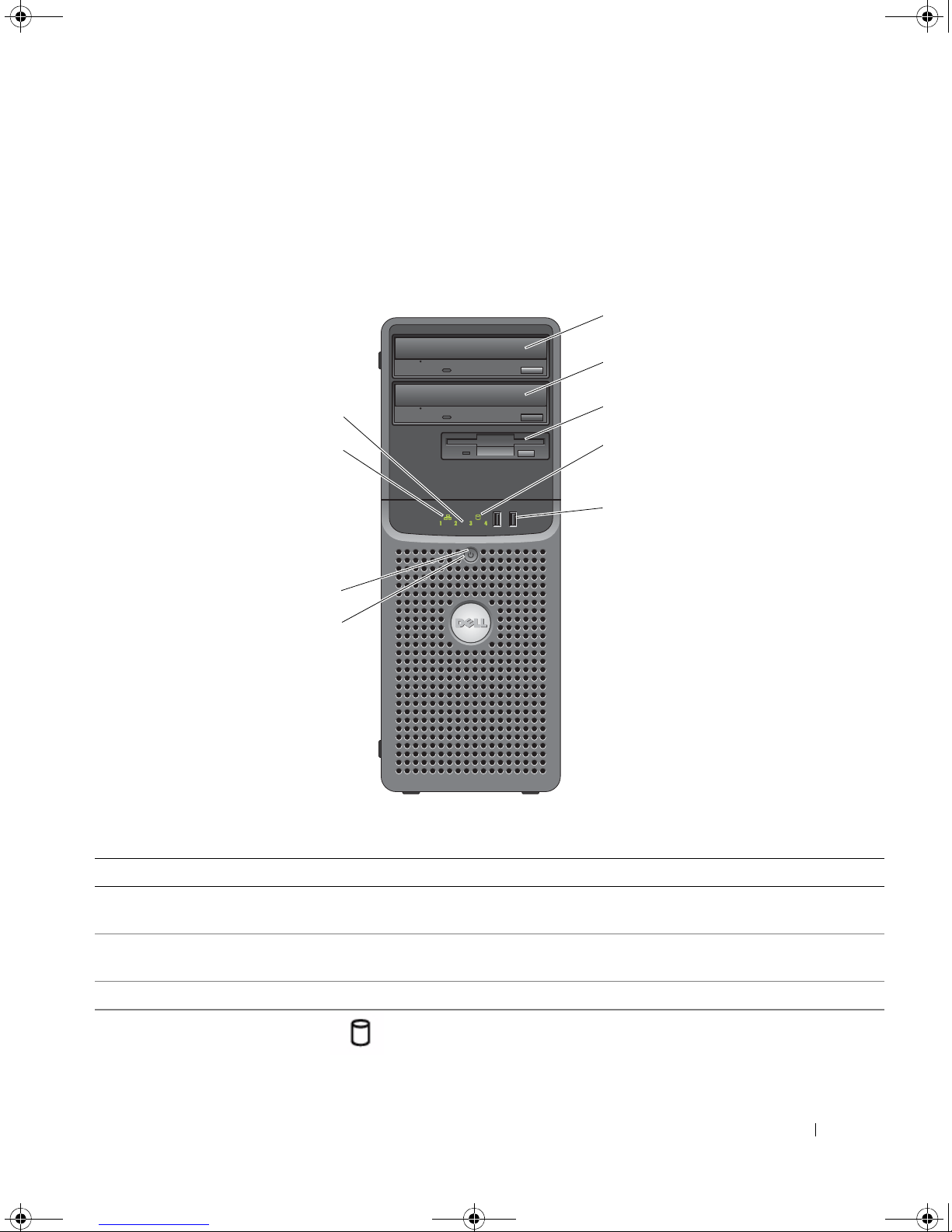
Front-Panel Features and Indicators
Figure 1-1 shows the controls, indicators, and connectors located on the system's front panel. Table 1-2
provides component descriptions.
Figure 1-1. Front-Panel Features and Indicators
Table 1-2. Front-Panel Components
Item Component Icon Description
1 upper 5.25-inch drive
bay
2 lower 5.25-inch drive
bay
3 flex bay Holds an optional diskette drive.
4 hard-drive activity
indicator
Holds an optical drive.
Holds an optional optical or tape backup unit drive.
Indicates hard drive activity.
About Your System 11
book.book Page 12 Tuesday, August 25, 2009 1:14 PM
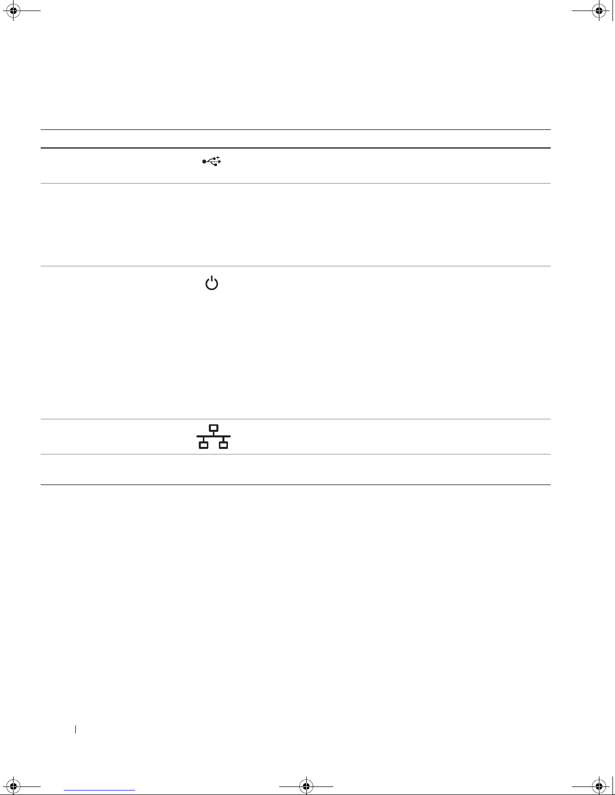
Table 1-2. Front-Panel Components (continued)
Item Component Icon Description
5 USB connectors (2) Connects USB 2.0-compliant devices to the system.
6 power button The power button controls the DC power supply output to the system.
NOTE: If you turn off the system using the power button and the system is
running an ACPI-compliant operating system, the system performs a
graceful shutdown before the power is turned off. If the system is not
running an ACPI-compliant operating system, the power is turned off
immediately after the power button is pressed.
7 power light No light — The system is off.
Steady green — The system is powered on.
Blinking green — The system is in a low power state.
Steady amber — The power supply is probably good.
Blinking amber — The system is powering up.
• If the hard drive indicator is off, the power supply may need to be
replaced.
• If the hard drive indicator is on, the system board is faulty. Check the
diagnostic indicators to see if the specific problem is identified. See
"Diagnostic Lights" on page 15.
8 network link light Lights when the system is linked to a network.
9 diagnostic lights (4) Display light-pattern codes to assist in troubleshooting system
problems.
See "Diagnostic Lights
" on page 15
.
12 About Your System

1
5
7
4
3
2
6
book.book Page 13 Tuesday, August 25, 2009 1:14 PM
Back-Panel Features and Indicators
Figure 1-2 shows the controls, indicators, and connectors located on the system's back panel.
Figure 1-2. Back-Panel Features and Indicators
1 voltage selection switch 2 power connector 3 NIC connector
4 USB connectors (5) 5 serial connector 6 video connector
7 I/O expansion-card slots (5)
Connecting External Devices
When connecting external devices to your system, follow these guidelines:
• Most devices must be connected to a specific connector and device drivers must be installed before the
device operates properly. (Device drivers are normally included with your operating system software or
with the device itself.) See the documentation that accompanied the device for specific installation
and configuration instructions.
About Your System 13
1
2
book.book Page 14 Tuesday, August 25, 2009 1:14 PM
• Always attach an external device while your system and the device are turned off. Next, turn on any
external devices before turning on the system (unless the documentation for the device specifies
otherwise).
See "Using the System Setup Program" on page 27 for information about enabling, disabling, and
configuring I/O ports and connectors.
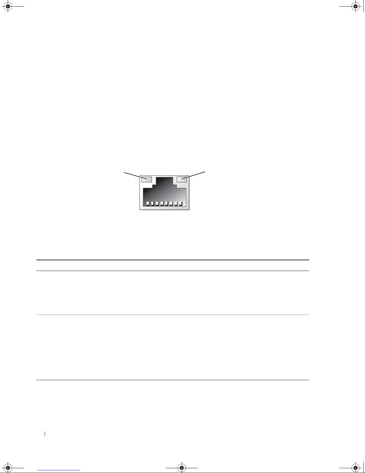
NIC Indicator Codes
The NIC on the back panel has an indicator that provides information on network activity and link
status. See Figure 1-3. Table 1-3 lists the NIC indicator codes.
Figure 1-3. NIC Indicators
1 link indicator 2 activity indicator
Table 1-3. NIC Indicator Codes
Indicator Type Indicator Code Description
Activity Off When off at the same time that the link indicator is off,
the NIC is not connected to the network or the NIC is
disabled in the System Setup program. See "Using the
System Setup Program" on page 27.
Blinking Indicates that network data is being sent or received.
Link Off When off at the same time that the activity indicator is
off, the NIC is not connected to the network or the NIC is
disabled in the System Setup program. See "Using the
System Setup Program" on page 27.
Yellow 1000-Mbps connection
Orange 100-Mbps connection
Green 10-Mbps connection
14 About Your System
book.book Page 15 Tuesday, August 25, 2009 1:14 PM
Power Supply Indicators
The voltage selection switch on the back panel of the system allows you to select one of two primary
voltage inputs. Ensure that the switch is set to the proper voltage according to Table 1-4.
Table 1-4. Voltage Selection Switch
If your power source is: The voltage selection switch should be set to:
110 V
220 V
115
230
For information on system power requirements, see "Technical Specifications" in your Getting Started
Guide.
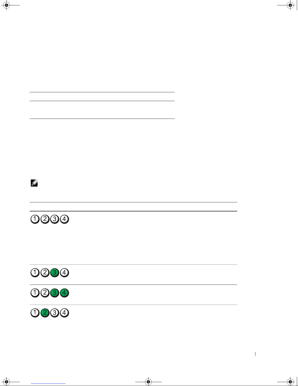
Diagnostic Lights
The four diagnostic indicator lights on the system front panel display error codes during system startup.
Table 1-5 lists the causes and possible corrective actions associated with these codes. A highlighted circle
indicates the light is on; a non-highlighted circle indicates the light is off.
NOTE: Once the system completes POST, all diagnostic lights will be OFF.
Table 1-5. Diagnostic Indicator Codes
Code Causes Corrective Action
The computer is in a
normal off condition or a
possible pre-BIOS failure
has occurred.
The diagnostic lights are
not lit after the system
successfully boots to the
operating system.
Plug the computer into a working electrical
outlet and press the power button.
Possible processor failure. See "Troubleshooting the Microprocessor" on
Memory failure. See "Troubleshooting System Memory" on
Possible expansion card
failure.
page 95.
page 87.
See "Troubleshooting Expansion Cards" on
page 93.
About Your System 15
book.book Page 16 Tuesday, August 25, 2009 1:14 PM
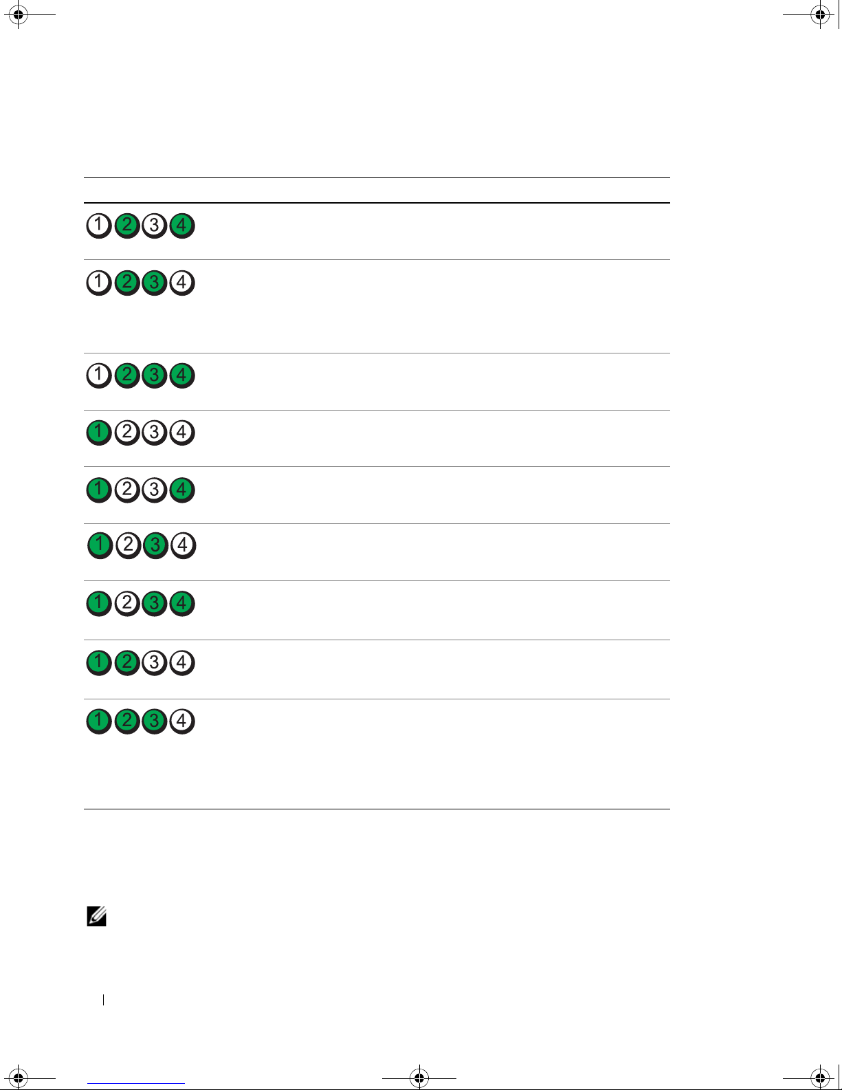
Table 1-5. Diagnostic Indicator Codes (continued)
Code Causes Corrective Action
Possible video failure. See "Getting Help" on page 107.
Diskette drive or hard
drive failure.
Possible USB failure. See "Troubleshooting a USB Device" on
No memory modules
detected.
System board failure. See "Getting Help" on page 107.
Memory configuration
error.
Possible system board
resource and/or system
board hardware failure.
Possible system resource
configuration error.
Ensure that the diskette drive and hard drive
are properly connected. See "Hard Drives" on
page 51 or "Diskette Drive" on page 44 for
information on the drives installed in your
system.
page 82.
See "Troubleshooting System Memory" on
page 87.
See "Troubleshooting System Memory" on
page 87.
See "Getting Help" on page 107.
See "Troubleshooting IRQ Assignment
Conflicts" on page 80. If the problem persists,
see "Getting Help" on page 107.
Other failure. Ensure that the diskette drive, optical drive,
System Messages
System messages appear on the screen to notify you of a possible problem with the system. Table 1-6 lists
the system messages that can occur and the probable cause and corrective action for each message.
NOTE: If you receive a system message that is not listed in Table 1-6, check the documentation for the application
that is running when the message appears or the operating system's documentation for an explanation of the
message and recommended action.
16 About Your System
and hard drives are properly connected. See
"Troubleshooting Your System" on page 79 for
the appropriate drive installed in your system.
If the problem persists, see "Getting Help" on
page 107.
book.book Page 17 Tuesday, August 25, 2009 1:14 PM
CAUTION: Many repairs may only be done by a certified service technician. You should only perform
troubleshooting and simple repairs as authorized in your product documentation, or as directed by the online or
telephone service and support team. Damage due to servicing that is not authorized by Dell is not covered by your
warranty. Read and follow the safety instructions that came with the product.
Table 1-6. System Messages
Message Causes Corrective Actions
A filename cannot contain
any of the following
characters:
\ / : * ? “ < > |
A required .DLL file was
not found
Alert! CPU fan not
detected
Alert! Previous reboot was
due to voltage regulator
failure
Alert! System battery
voltage is low
Alert! Unable to initialize all installed memory
The application that you are trying to
open is missing an essential file.
The processor cooling fan is faulty or
the fan assembly is not installed
correctly.
One or more memory modules might
be faulty or improperly seated.
Do not use these characters in filenames.
Remove and then reinstall the
application.
See the application’s documentation for
installation instructions.
Ensure that the processor cooling fan is
properly installed. See "Troubleshooting
System Cooling Problems" on page 86.
See "Getting Help" on page 107.
Replace the battery. See
"Troubleshooting the System Battery" on
page 85.
See "Troubleshooting System Memory"
on page 87.
If the problem persists, see "Getting
Help" on page 107.
Alert! Card-cage fan
failure.
Alert! Chipset heat sink
not detected.
Alert! Cover was
previously removed.
A card-cage fan is not detected during
POST. The system will halt at the
See "Troubleshooting System Cooling
Problems" on page 86.
<F1>/<F2> prompt even if
Keyboard Errors Report option is
disabled in the System Setup
program.
Ensure heat sink and shroud assembly
are properly attached. See Figure 3-15.
The system was opened. Information only. To reset the chassis
intrusion switch, see "Using the System
Setup Program" on page 27.
About Your System 17

book.book Page 18 Tuesday, August 25, 2009 1:14 PM
Table 1-6. System Messages (continued)
Message Causes Corrective Actions
Alert! CPU fan failure. The processor cooling fan is faulty or
the fan assembly is not installed
correctly.
Alert! Error initializing
PCI Express slot n (or
bridge).
The system encountered a problem
while trying to configure a PCIe
expansion card.
Alert! Incompatible
processor detected.
Alert! OS Install Mode
enabled. Amount of
available memory limited
to 256MB.
The OS Install Mode option in the
System Setup program is set to On.
This limits the amount of available
memory to 256 MB because some
operating systems will not complete
installation with more than 2 GB of
system memory.
Alert! Previous fan
failure.
The fan caused errors the last time the
system was used.
Ensure that the processor cooling shroud
is properly installed. See
"Troubleshooting System Cooling
Problems" on page 86 and
"Microprocessor" on page 62.
See "Troubleshooting Expansion Cards"
on page 93.
Use only Dell supported processors. See
the Getting Started Guide for a list of
supported processors.
After the operating system is installed,
enter the System Setup program and set
the OS Install Mode option to Off. See
"Using the System Setup Program" on
page 27.
Ensure that nothing is blocking the
airflow vents and that all fans are
properly installed and operating
correctly. See "Troubleshooting System
Cooling Problems" on page 86.
Alert! Previous attempts
at booting this system
have failed at checkpoint
[nnnn]. For help in
resolving this problem,
please note this
checkpoint and contact
Dell Technical Support.
Alert! Previous Processor
Thermal Failure
18 About Your System
The system failed to complete the
boot routine three consecutive times
for the same error.
The processor overheated the last
time the system was used.
See "Getting Help" on page 107.
Ensure that nothing is blocking the
airflow vents and that all fans are
properly installed and operating
correctly. Also, ensure that the processor
heat sink is properly installed. See
"Microprocessor" on page 62.
book.book Page 19 Tuesday, August 25, 2009 1:14 PM
Table 1-6. System Messages (continued)
Message Causes Corrective Actions
Alert! Previous Shutdown
Due to Thermal Event
The processor or hard drive
overheated the last time the system
was used.
Ensure that nothing is blocking the
airflow vents and that all fans are
working correctly. Also, ensure that the
processor heat sink is properly installed.
See "Microprocessor" on page 62.
Alert! Uncorrectable
Memory Error Previously
Detected... Address
XXXXXXXX
H, Device DIMM_
Attachment failed to
respond
One or more memory modules might
be improperly seated or faulty, or the
system board may be faulty.
Y
The diskette or hard-drive controller
cannot send data to the associated
drive.
See "Troubleshooting System Memory"
on page 87.
If the problem persists, see "Getting
Help" on page 107.
See "Troubleshooting a Diskette Drive"
on page 89 or "Troubleshooting a Hard
Drive" on page 91.
Bad command or file name Ensure that you have spelled the
command correctly, have put spaces in
the proper place, and have used the
correct pathname.
Bad error-correction code
(ECC) on disk read
The diskette or hard-drive controller
detected an uncorrectable read error.
See "Troubleshooting a Diskette Drive"
on page 89 or "Troubleshooting a Hard
Drive" on page 91.
bb/dd/f
IRQ for PCI Device
bb/dd/f
I/O BAR for PCI Device
bb/dd/f
Mem BAR for PCI Device
bb/dd/f
: Error allocating
: Error allocating
: Error allocating
: Error allocating
The system encountered a problem
while trying to configure an expansion
card or integrated on-board devices.
If the device number points to an
expansion card, the card can be removed.
See "Troubleshooting Expansion Cards"
on page 93.
If the device number points to a an on-
board device, disable the device. See
"Using the System Setup Program" on
page 27.
PMem BAR for PCI Device
bb/dd/f
: Error allocating
UMB for PCI Device
NOTE:
device number, and
bb
is the bus number, dd is the
f
is the function
number. All numbers are hexadecimal.
Controller has failed The hard drive or the associated
controller is defective.
See "Troubleshooting a Hard Drive" on
page 91.
About Your System 19
book.book Page 20 Tuesday, August 25, 2009 1:14 PM
Table 1-6. System Messages (continued)
Message Causes Corrective Actions
Data error The diskette drive or hard drive
cannot read the data.
For the operating system, run the
appropriate utility to check the file
structure of the diskette drive or hard
drive. See your operating system
documentation for information on
running these utilities.
Decreasing available
memory
One or more memory modules might
be faulty or improperly seated.
Reinstall the memory modules and, if
necessary, replace them. See
"Troubleshooting System Memory" on
page 87.
Diskette drive 0 seek
failure
A cable might be loose or the system
configuration information might not
See "Troubleshooting a Diskette Drive"
on page 89.
match the hardware configuration.
Diskette read failure The diskette might be defective, or a
cable might be loose.
If the diskette-drive indicator turns on,
try a different disk. See "Troubleshooting
a Diskette Drive" on page 89.
Diskette subsystem reset
failed
The diskette drive controller might be
faulty.
Run the system diagnostics. See
"Running the System Diagnostics" on
page 98.
Diskette write protected The diskette is write-protected. Slide the write-protect notch to the open
position.
Drive not ready No diskette is in the drive. Insert a diskette in the drive.
Error auto-sensing primary
master hard disk drive
See "Troubleshooting a Hard Drive" on
page 91.
Error auto-sensing primary
slave hard disk drive
Error auto-sensing
secondary master hard disk
drive
Error auto-sensing
secondary slave hard disk
drive
Floppy diskette seek
failure
A diskette drive is not connected but
is enabled in the BIOS setup menu.
See "Troubleshooting a Diskette Drive"
on page 89.
The diskette in the drive is faulty.
Gate A20 failure Faulty keyboard controller (faulty
See "Getting Help" on page 107.
system board).
20 About Your System
book.book Page 21 Tuesday, August 25, 2009 1:14 PM
Table 1-6. System Messages (continued)
Message Causes Corrective Actions
General failure The operating system is unable to
carry out the command.
Hard-disk configuration
error
Hard-disk controller
failure
Hard-disk drive failure
x
Drive
(or Parallel) ATA, SATA(or PATA-)
NOTE:
and
Insert bootable media The operating system is trying to boot
Invalid configuration
information - please run
SETUP program
Keyboard Controller
Failure
Keyboard Stuck Key Failure
Keyboard failure
not found: Serial
n
x
is the drive number (0-6)
n
is SATA0-3 or PATA0-1.
The hard drive failed initialization. Run the system diagnostics. See
from a nonbootable diskette or CD.
The system configuration information
does not match the hardware
configuration.
A cable or connector might be loose,
or the keyboard or keyboard/mouse
controller might be faulty.
This message is usually followed by
specific information. Take the
appropriate action to resolve the
problem.
"Running the System Diagnostics" on
page 97. Also, see "Troubleshooting a
Hard Drive" on page 91.
Run the system diagnostics. See
"Running the System Diagnostics" on
page 97. Also, see "Troubleshooting a
Hard Drive" on page 91.
Insert a bootable diskette or CD.
Enter the System Setup program and
correct the system configuration
information. See "Using the System
Setup Program" on page 27.
See "Troubleshooting the Keyboard" on
page 81.
Keyboard fuse has failed. See "Troubleshooting the Keyboard" on
Memory address line
failure at
value
Memory allocation error The software you are attempting to
expecting
address
, read
value
A memory module might be faulty or
improperly seated.
run is conflicting with the operating
system, another program, or a utility.
page 81.
Reinstall the memory modules and, if
necessary, replace them. See
"Troubleshooting System Memory" on
page 87.
Turn off the system, wait 30 seconds,
restart the system, and then try to run
the program again. If the error message
appears again, see the software
documentation for additional
troubleshooting suggestions.
About Your System 21

book.book Page 22 Tuesday, August 25, 2009 1:14 PM
Table 1-6. System Messages (continued)
Message Causes Corrective Actions
Memory data line failure
address
at
expecting
, read
value
value
Memory double word logic
failure at
value
expecting
address
value
, read
Memory odd/even logic
failure at
value
expecting
address
, read
value
Memory write/read failure
address
at
expecting
, read
value
value
Memory size in CMOS
invalid
Memory type or speed is not
supported on this system.
Please refer to system
documentation for support
memory configurations.
A memory module might be faulty or
improperly seated.
The amount of memory recorded in
the system configuration information
does not match the memory installed
in the system.
Reinstall the memory modules and, if
necessary, replace them. See
"Troubleshooting System Memory" on
page 87.
Restart the system. If the error message
appears again, see "Troubleshooting
System Memory" on page 87. If the
problem persists, see "Getting Help" on
page 107.
See "Troubleshooting System Memory"
on page 87.
NIC failure. See "Troubleshooting a NIC" on page 83.
No boot device available The system cannot find the diskette or
hard drive.
If the diskette drive is your boot device,
ensure that a bootable disk is in the
drive.
If the hard drive is your boot device,
ensure that the hard drive is installed,
the interface cable is properly connected,
and the hard drive is partitioned as a
boot device.
Enter the System Setup program and
verify the boot sequence information.
See "Using the System Setup Program"
on page 27.
22 About Your System

book.book Page 23 Tuesday, August 25, 2009 1:14 PM
Table 1-6. System Messages (continued)
Message Causes Corrective Actions
No boot sector on
hard-disk drive
The system configuration information
in the System Setup program might
be incorrect.
No timer tick interrupt A chip on the system board might be
malfunctioning.
Non-system disk or disk
error
The diskette in the diskette drive or
your hard drive does not have a
bootable operating system installed
on it.
Enter the System Setup program and
verify the system configuration
information for the hard drive. See
"Using the System Setup Program" on
page 27.
If the message continues to appear after
verifying the information in the System
Setup program, the operating system
might have been corrupted.
Reinstall the
operating system. See your operating
system documentation for reinstallation
information.
Run the system diagnostics. See
"Running the System Diagnostics" on
page 97.
Replace the diskette with one that has a
bootable operating system or remove the
diskette, and then restart the system.
If the problem persists, see
"Troubleshooting a Diskette Drive" on
page 89 or "Troubleshooting a Hard
Drive" on page 91.
If the problem persists, see "Getting
Help" on page 107.
Not a boot diskette The operating system is trying to boot
from a diskette that does not have a
bootable operating system installed
on it.
Not enough memory or
You have too many programs open. Close all windows and open the program
resources. Close some
programs and try again.
Mixing ECC and non-ECC
DIMMs is not supported on
this platform
Insert a diskette that has a bootable
operating system.
that you want to use. In some cases, you
might have to restart your system to
restore system resources. If so, try
opening the program that you want to
use first
See "Troubleshooting System Memory"
on page 87. If the problem persists, see
"Getting Help" on page 107.
About Your System 23

book.book Page 24 Tuesday, August 25, 2009 1:14 PM
Table 1-6. System Messages (continued)
Message Causes Corrective Actions
Operating system not found See "Troubleshooting a Hard Drive" on
page 91. If the problem persists, see
"Getting Help" on page 107.
Please connect USB
keyboard/mouse to USB
The keyboard and/or mouse is not
properly connected.
See "Troubleshooting a USB Device" on
page 82.
ports on the back of the
computer
Plug and play
configuration error
Read fault The operating system cannot read
An attached device is improperly
configured.
from the diskette or hard drive, the
system could not find a particular
See "Troubleshooting Your System" on
page 79.
See "Troubleshooting a Diskette Drive"
on page 89 or "Troubleshooting a Hard
Drive" on page 91.
sector on the disk, or the requested
sector is defective.
Requested sector not found The operating system cannot read
from the diskette or hard drive, the
system could not find a particular
See "Troubleshooting a Diskette Drive"
on page 89 or "Troubleshooting a Hard
Drive" on page 91.
sector on the disk, or the requested
sector is defective.
Reset failed The disk reset operation failed. See "Troubleshooting a Diskette Drive"
on page 89 or "Troubleshooting a Hard
Drive" on page 91.
Sector not found
Seek error
A faulty diskette drive or hard drive. See "Troubleshooting a Diskette Drive"
on page 89 or "Troubleshooting a Hard
Drive" on page 91.
Shutdown failure A chip on the system board might be
The amount of system
memory has changed
The file being copied is
too large for the
destination drive.
24 About Your System
malfunctioning.
Memory has been added or removed,
or a memory module may be faulty.
The file that you are trying to copy is
too large to fit on the disk.
Run the system diagnostics. See
"Running the System Diagnostics" on
page 97.
If memory has been added or removed,
this message is informative and can be
ignored. If memory has not been added
or removed, check the SEL to determine
if single-bit or multi-bit errors were
detected and replace the faulty memory
module. See "Troubleshooting System
Memory" on page 87.
Try increasing disk space on the
destination drive by deleting
unnecessary files.
book.book Page 25 Tuesday, August 25, 2009 1:14 PM
Table 1-6. System Messages (continued)
Message Causes Corrective Actions
Time-of-day clock stopped The battery might be faulty. See "Troubleshooting the System
Battery" on page 85.
Time-of-day not set The time or date stored in the System
Setup program does not match the
system clock.
Timer chip counter 2
failed
Unexpected interrupt in
protected mode
Write fault
Write fault on selected
drive
<drive letter>
accessible. The device is
not ready.
:\ is not
A chip on the system board might be
malfunctioning.
The operating system cannot write to
the diskette drive or hard drive.
The diskette drive cannot read the
diskette.
Warning Messages
Enter the System Setup program and
correct the Date and Time options. See
"Using the System Setup Program" on
page 27. If the problem persists, see
"Troubleshooting the System Battery" on
page 85.
Run the system diagnostics. See
"Running the System Diagnostics" on
page 97.
Run the system diagnostics. See
"Running the System Diagnostics" on
page 97.
See "Troubleshooting a Diskette Drive"
on page 89 or "Troubleshooting a Hard
Drive" on page 91.
Insert a diskette into the drive or replace
the existing diskette, and try again.
A warning message alerts you to a possible problem and prompts you to respond before the system
continues a task. For example, before you format a diskette, a message will warn you that you may lose all
data on the diskette. Warning messages usually interrupt the task and require you to respond by typing
(yes) or
n (no).
NOTE: Warning messages are generated by either the application or the operating system. For more information,
see the documentation that accompanied the operating system or application.
About Your System 25
y

book.book Page 26 Tuesday, August 25, 2009 1:14 PM
Diagnostics Messages
When you run system diagnostics, an error message may result. Diagnostic error messages are not
covered in this section. Record the message on a copy of the Diagnostics Checklist in "Getting Help" on
page 107, and then follow the instructions in that section for obtaining technical assistance.
Alert Messages
Systems management software generates alert messages for your system. Alert messages include
information, status, warning, and failure messages for drive, temperature, fan, and power conditions. For
more information, see the systems management software documentation.
26 About Your System

book.book Page 27 Tuesday, August 25, 2009 1:14 PM
Using the System Setup Program
After you set up your system, run the System Setup program to familiarize yourself with your system
configuration and optional settings. Record the information for future reference.
You can use the System Setup program to:
• Change the system configuration stored in NVRAM after you add, change, or remove hardware
• Set or change user-selectable options—for example, the time or date
• Enable or disable integrated devices
• Correct discrepancies between the installed hardware and configuration settings
Entering the System Setup Program
During System Setup
1
Turn on or restart your system.
2
Press <F2> immediately after you see the following message:
<F2> = System Setup
If your operating system begins to load before you press <F2>, allow the system to finish booting,
and then restart your system and try again.
NOTE: To ensure an orderly system shutdown, see the documentation that accompanied your operating
system.
Responding to Error Messages
You can enter the System Setup program by responding to certain error messages. If an error message
appears while the system is booting, make a note of the message. Before entering the System Setup
program, see "System Messages
correcting errors.
NOTE: After installing a memory upgrade, it is normal for your system to send a message the first time you
start your system.
" on page 16
for an explanation of the message and suggestions for
Navigating the System Setup Program
Table 2-1 lists the keys that you use to view or change information on the System Setup screens, and to
exit the program.
Using the System Setup Program 27
book.book Page 28 Tuesday, August 25, 2009 1:14 PM
Table 2-1. System Setup Program Navigation Keys
Keys Action
Up arrow and down arrow Moves to the previous or next field
Left arrow and right arrow Moves left or right in a field
<+> and <–> keys Opens and closes submenus
<Enter> Allows you to view the details for or modify an option,
<Esc> Either moves your cursor back to the option menu
or allows you to confirm your setting change and moves
the cursor back to the option menu
without modifying an option, or opens the System
Setup
Exit
screen
NOTE: For most of the options, any changes that you make are recorded but do not take effect until you restart the
system.
Exiting the System Setup Program
If you have made no changes in the BIOS, the
<Esc> to exit the System Setup program:
•
Remain in Setup
•
Exit
If you have made changes in the BIOS, the
to exit the System Setup program:
•
Remain in Setup
•
Save/Exit
•
Discard/Exit
Exit
screen displays the following options after you press
Exit
screen displays the following options after you press <Esc>
System Setup Options
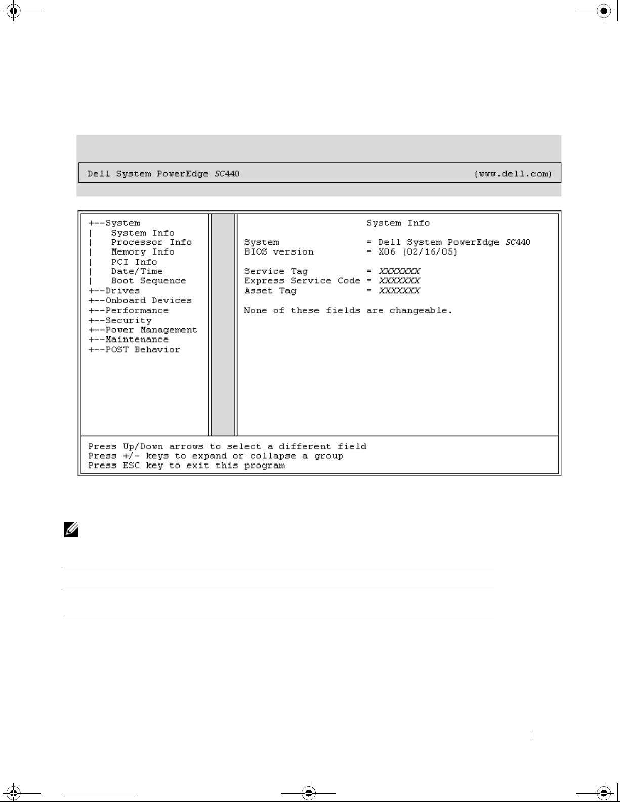
Main Screen
Figure 2-1 shows an example of the main screen.
28 Using the System Setup Program
book.book Page 29 Tuesday, August 25, 2009 1:14 PM
Figure 2-1. Main System Setup Program Screen
Table 2-2 through Table 2-9 lists the options and descriptions for each group of information fields that
appear on the main System Setup program screen.
NOTE: The System Setup program defaults are listed under their respective options, where applicable.
Table 2-2. System Options
Option Description
System Info
Processor Info
Displays the
Express Service Code
System
name,
, and
BIOS Version
Asset Tag
.
number,
BIOS Date, Service Tag,
Displays the following information for the processor installed in the system:
Processor Type, Processor Clock Speed, Processor Bus Speed, Processor
Cache Size, Processor ID
Capable
Technology
, or
Hyperthreading Capable
.
number, whether the processor is
, and if the processor has
Multiple Core
64-bit
Using the System Setup Program 29

book.book Page 30 Tuesday, August 25, 2009 1:14 PM
Table 2-2. System Options (continued)
Option Description
Memory Info
Displays the amount of
Channel Mode
also displays a table that describes the memory size, whether the memory
module is ECC capable, single or dual rank, type, and organization for each
DIMM socket.
PCI Info
Date/Time
Boot Sequence
(Diskette drive default)
Displays the types of cards that are installed in the PCI slots, if applicable.
Resets the system’s internal calendar and clock.
Determines the order in which the system searches for boot devices during
system startup. Available options can include the diskette drive, CD drive,
hard drives, and USB devices.
Table 2-3. Drive Options
Option Description
Diskette Drive
(Internal default)
Enables and disables the diskette drives and sets read permission for the
internal diskette drive.
internal diskette drive and enables a USB drive if the USB controller is
enabled and a USB drive is connected.
diskette drive.
the internal diskette drive read-only permission.
NOTE: Diskette drives are optional and may not be part of your system.
Installed Memory, Memory Speed, Memory
, and a description of the
Off
disables all diskette drives.
Read Only
enables the internal drive controller and allows
Memory Technology
USB
Internal
enables the internal
. This option
disables the
SATA0-3
Enables or disables a
device (such as hard drive, CD drive, or DVD drive).
interface so that the device cannot be used.
that the device can be used.
Displays the Controller type, Port number the drive is using, Drive ID
number, Capacity, whether the drive is controlled by the BIOS, and Link
Speed.
PATA 0- 1
Enables or disables a
(such as hard drive or IDE drive).
device cannot be used.
used.
Displays the Controller type, Port number the drive is using, Drive ID
number, Capacity, whether the drive is controlled by the BIOS, and Link
Speed.
SMART Reporting
(Off default)
Determines whether hard-drive errors for internal drives are reported during
system startup.
30 Using the System Setup Program
Serial Advanced Technology Attachment (S
Off
On
enables the interface so
Parallel Advanced Technology Attachment
Off
disables the interface so that the
On
enables the interface so that the device can be
Off
does not report errors. On reports errors.
ATA)
disables the
device
 Loading...