

Dell PowerEdge HX574, PowerEdge R905 Hardware Owner's Manual

Dell™ PowerEdge™ R905
Hardware Owner’s
Manual

Notes, Notices, and Cautions
NOTE: A NOTE indicates important information that helps you make better use of
your computer.
NOTICE: A NOTICE indicates either potential damage to hardware or loss of data
and tells you how to avoid the problem.
CAUTION: A CAUTION indicates a potential for property damage, personal injury,
or death.
____________________
Information in this document is subject to change without notice.
© 2007-2009 Dell Inc. All rights reserved.
Reproduction in any manner whatsoever without the written permission of Dell Inc. is strictly
forbidden.
Trademarks used in this text: Dell, the DELL logo, PowerEdge, and Dell OpenManage are trademarks
of Dell Inc.; AMD, AMD Opteron, and combinations thereof are trademarks of Advanced Micro
Devices, Inc.; Microsoft, Windows, Windows Server, and MS-DOS are either trademarks or registered
trademarks of Microsoft Corporation in the United States and/or other countries.
Other trademarks and trade names may be used in this document to refer to either the entities claiming
the marks and names or their products. Dell Inc. disclaims any proprietary interest in trademarks and
trade names other than its own.
September 2009 P/N HX574 Rev. A02

Contents
1 About Your System. . . . . . . . . . . . . . . . . . 11
Other Information You May Need . . . . . . . . . . . . 11
Accessing System Features During Startup
. . . . . . . 12
Front-Panel Features and Indicators . . . . . . . . . . 13
Hard-Drive Indicator Codes
Back-Panel Features and Indicators
Connecting External Devices
Power Indicator Codes
NIC Indicator Codes
LCD Status Messages
. . . . . . . . . . . . . . . . . 19
. . . . . . . . . . . . . . . . . . . 20
. . . . . . . . . . . . . . . . . . 21
. . . . . . . . . . . . 16
. . . . . . . . . . 17
. . . . . . . . . . . . 18
Solving Problems Described by LCD
Status Messages
Removing LCD Status Messages
System Messages
. . . . . . . . . . . . . . . . . . 32
. . . . . . . . . . 32
. . . . . . . . . . . . . . . . . . . . 33
Warning Messages
Diagnostics Messages
Alert Messages
. . . . . . . . . . . . . . . . . . . 43
. . . . . . . . . . . . . . . . . 43
. . . . . . . . . . . . . . . . . . . . . 43
Contents 3

2 Using the System Setup Program . . . . . 45
Entering the System Setup Program . . . . . . . . . . . 45
Responding to Error Messages
Using the System Setup Program
System Setup Options
. . . . . . . . . . . . . . . . . . 46
. . . . . . . . . . . 45
. . . . . . . . . . 46
Main Screen. . . . . . . . . . . . . . . . . . . . . . . . . . . . . . . . . . .
Memory Information Screen
CPU Information Screen
Integrated Devices Screen
Serial Communication Screen
System Security Screen
Exit Screen
. . . . . . . . . . . . . . . . . . . . . 56
System and Setup Password Features
Using the System Password
Using the Setup Password
Disabling a Forgotten Password
. . . . . . . . . . . . 49
. . . . . . . . . . . . . . 50
. . . . . . . . . . . . . 51
. . . . . . . . . . . 53
. . . . . . . . . . . . . . 53
. . . . . . . . . . 56
. . . . . . . . . . . . 57
. . . . . . . . . . . . . 59
. . . . . . . . . . . . . 61
46
3 Installing System Components . . . . . . . 63
4 Contents
Baseboard Management Controller Configuration
Entering the BMC Setup Module
BMC Setup Module Options
. . . . . . . . . . 61
. . . . . . . . . . . . 61
. . . 61
Recommended Tools . . . . . . . . . . . . . . . . . . . 64
Inside the System
Removing and Replacing the Optional Front Bezel
Opening and Closing the System
Opening the System
Closing the System
. . . . . . . . . . . . . . . . . . . . . 64
. . . 66
. . . . . . . . . . . . 67
. . . . . . . . . . . . . . . . . 67
. . . . . . . . . . . . . . . . . 68

Cooling Fans . . . . . . . . . . . . . . . . . . . . . . . 69
Removing a Cooling Fan
Replacing a Cooling Fan
Cooling Shroud Assembly
. . . . . . . . . . . . . . 69
. . . . . . . . . . . . . . 70
. . . . . . . . . . . . . . . . 71
Removing the Cooling Shroud Assembly
Replacing the Cooling Shroud Assembly
Power Supplies
Removing a Power Supply
Replacing a Power Supply
Processor Expansion Module
. . . . . . . . . . . . . . . . . . . . . 73
. . . . . . . . . . . . . 73
. . . . . . . . . . . . . 74
. . . . . . . . . . . . . . 75
Removing the PEM or PEM Shell
Replacing the PEM or PEM Shell
Expansion Cards
. . . . . . . . . . . . . . . . . . . . . 79
Expansion Card Installation Guidelines
. . . . . . 71
. . . . . . 72
. . . . . . . . . . 75
. . . . . . . . . . 78
. . . . . . 79
Installing an Expansion Card
Removing an Expansion Card
Riser Board
. . . . . . . . . . . . . . . . . . . . . . . . 83
Removing the Riser Board
Replacing the Riser Board
RAC Card
. . . . . . . . . . . . . . . . . . . . . . . . . 86
. . . . . . . . . . . . 80
. . . . . . . . . . . 83
. . . . . . . . . . . . . 84
. . . . . . . . . . . . . 85
Installing an Optional RAC Card
Internal USB Memory Key (Optional)
Installing the Optional Internal USB
Memory Key
TOE/iSCSI Key (Optional)
SD Memory Card
. . . . . . . . . . . . . . . . . . . . 88
. . . . . . . . . . . . . . . . 89
. . . . . . . . . . . . . . . . . . . . . 91
. . . . . . . . . . 86
. . . . . . . . . . 88
Contents 5

NIC Daughter Card . . . . . . . . . . . . . . . . . . . . 91
Installing the NIC Daughter Card
Removing the NIC Daughter Card
System Memory
. . . . . . . . . . . . . . . . . . . . . 94
General Memory Module
Installation Guidelines
Installing Memory Modules
Removing Memory Modules
Processors
. . . . . . . . . . . . . . . . . . . . . . . 100
Removing a Processor
Installing a Processor
Installing an Optical Drive
Hard Drives
Before You Begin
. . . . . . . . . . . . . . . . . . . . . . . 107
. . . . . . . . . . . . . . . . . 108
Configuring the Boot Device
. . . . . . . . . . 91
. . . . . . . . . 93
. . . . . . . . . . . . . . . 94
. . . . . . . . . . . . . 97
. . . . . . . . . . . . 99
. . . . . . . . . . . . . . 101
. . . . . . . . . . . . . . . 103
. . . . . . . . . . . . . . . 105
. . . . . . . . . . . 109
Removing a Drive Blank
Installing a Drive Blank
Removing a Hot-Plug Hard Drive
Installing a Hot-Plug Hard Drive
. . . . . . . . . . . . . . 109
. . . . . . . . . . . . . . 109
. . . . . . . . . 110
. . . . . . . . . 111
Replacing a Hard Drive in a
Hard-Drive Carrier
SAS Controller Cards
Removing a SAS Controller Card
Installing a SAS Controller Card
. . . . . . . . . . . . . . . . 112
. . . . . . . . . . . . . . . . . . 113
. . . . . . . . . 113
. . . . . . . . . 114
Installing the SAS RAID Controller
Card Battery
. . . . . . . . . . . . . . . . . . . . 115
Connecting an External SAS Tape Drive
Connecting an External Fibre Channel
Storage Device
. . . . . . . . . . . . . . . . . . . . . 116
. . . . . . . 116
6 Contents

System Battery . . . . . . . . . . . . . . . . . . . . . . 117
Replacing the System Battery
Control Panel Assembly
Removing the Control Panel
Installing the Control Panel
Chassis Intrusion Switch
. . . . . . . . . . . . . . . . . 119
. . . . . . . . . . . . 119
. . . . . . . . . . . . . 121
. . . . . . . . . . . . . . . . 122
Removing the Chassis Intrusion Switch
Installing the Chassis Intrusion Switch
SAS Backplane
. . . . . . . . . . . . . . . . . . . . . 124
Removing the SAS Backplane
Installing a SAS Backplane
Peripheral Interposer Board
. . . . . . . . . . . . . 127
. . . . . . . . . . . . . . . 128
Removing a Peripheral Interposer Board
Replacing a Peripheral Interposer Board
. . . . . . . . . . . 117
. . . . . . 122
. . . . . . 123
. . . . . . . . . . . 124
. . . . . 128
. . . . . 131
Fan Interposer Board
. . . . . . . . . . . . . . . . . . 131
Removing a Fan Interposer Board
Installing a Fan Interposer Board
System Board
Removing the System Board
Installing the System Board
Power Distribution Board
. . . . . . . . . . . . . . . . . . . . . . 134
. . . . . . . . . . . . 134
. . . . . . . . . . . . 137
. . . . . . . . . . . . . . . . 138
Removing the Power Distribution Board
Installing the Power Distribution Board
Processor Expansion Module Board
Removing the PEM Board
Replacing the PEM Board
. . . . . . . . . . . . . 141
. . . . . . . . . . . . . 142
. . . . . . . . . 131
. . . . . . . . . 133
. . . . . . 138
. . . . . . 140
. . . . . . . . . . 141
Contents 7

4 Troubleshooting Your System . . . . . . . . 145
Safety First—For You and Your System . . . . . . . . 145
Start-Up Routine
Checking Basic Power Problems
Checking the Equipment
. . . . . . . . . . . . . . . . . . . . 145
. . . . . . . . . . . 146
. . . . . . . . . . . . . . . . 146
Troubleshooting External Connections
Troubleshooting the Video Subsystem
Troubleshooting the Keyboard or Mouse
Troubleshooting Serial I/O Problems
Troubleshooting a Serial I/O Device
Troubleshooting a USB Device
Troubleshooting a NIC
Troubleshooting a Wet System
. . . . . . . . . . . . . . . . . 153
. . . . . . . . . . . . . 154
Troubleshooting a Damaged System
. . . . . . 147
. . . . . . 147
. . . . . 148
. . . . . . . . . 150
. . . . . . . 150
. . . . . . . . . . 151
. . . . . . . . . . 155
8 Contents
Troubleshooting the System Battery
Troubleshooting Power Supplies
. . . . . . . . . . 155
. . . . . . . . . . . 156
Troubleshooting System Cooling Problems
Troubleshooting a Fan
Troubleshooting System Memory
Troubleshooting an Optical Drive
Troubleshooting a Hard Drive
. . . . . . . . . . . . . . 157
. . . . . . . . . . . 158
. . . . . . . . . . . 160
. . . . . . . . . . . . . 161
Troubleshooting a SAS Controller or SAS
RAID Controller
. . . . . . . . . . . . . . . . . . . . . 163
Troubleshooting an External SAS Tape Drive
. . . . . . 157
. . . . . 165

Troubleshooting Expansion Cards. . . . . . . . . . . . 166
Troubleshooting the Microprocessors
. . . . . . . . . 167
5 Running the System Diagnostics . . . . . . 169
Using Dell PowerEdge Diagnostics . . . . . . . . . . . 169
System Diagnostics Features
When to Use the System Diagnostics
Running the System Diagnostics
System Diagnostics Testing Options
Using the Custom Test Options
Selecting Devices for Testing
Selecting Diagnostics Options
Viewing Information and Results
. . . . . . . . . . . . . . 169
. . . . . . . . . . 170
. . . . . . . . . . . . 170
. . . . . . . . . . 170
. . . . . . . . . . . . . 171
. . . . . . . . . . . 171
. . . . . . . . . . . 171
. . . . . . . . . . 172
6 Jumpers and Connectors . . . . . . . . . . . 173
System Board Jumpers . . . . . . . . . . . . . . . . . 173
Disabling a Forgotten Password . . . . . . . . . . . . 173
System Board Connectors
Processor Expansion Module Board Connectors
SAS Backplane Board Connectors
SAS 2.5-Inch Peripheral Interposer Board
. . . . . . . . . . . . . . . . 174
. . . . 177
. . . . . . . . . . . 178
. . . . . . . 179
Contents 9

7 Getting Help . . . . . . . . . . . . . . . . . . . . . . 181
Contacting Dell. . . . . . . . . . . . . . . . . . . . . 181
Glossary . . . . . . . . . . . . . . . . . . . . . . . . . . . . 183
Index
. . . . . . . . . . . . . . . . . . . . . . . . . . . . . . 195
10 Contents

About Your System
This section describes the physical, firmware, and software interface features
that provide and ensure the essential functioning of your system. The
physical connectors on your system’s front and back panels provide
convenient connectivity and system expansion capability. The system
firmware, applications, and operating systems monitor the system and
component status and alert you when a problem arises. System conditions
can be reported by any of the following:
• Front or back panel indicators
• LCD status messages
• System messages
• Warning messages
• Diagnostics messages
• Alert messages
This section describes each type of message, lists the possible causes, and
provides steps to resolve any problems indicated by a message. The system
indicators and features are illustrated in this section.
Other Information You May Need
CAUTION: The Product Information Guide provides important safety and
regulatory information. Warranty information may be included within this
document or as a separate document.
• The
• The
• CDs included with your system provide documentation and tools for
• Systems management software documentation describes the features,
Rack Installation Guide
with your rack solution describes how to install your system into a rack.
Getting Started Guide
up your system, and technical specifications.
configuring and managing your system.
requirements, installation, and basic operation of the software.
or
Rack Installation Instructions
provides an overview of system features, setting
About Your System 11
included

• Operating system documentation describes how to install (if necessary),
configure, and use the operating system software.
• Documentation for any components you purchased separately provides
information to configure and install these options.
• Updates are sometimes included with the system to describe changes to
the system, software, and/or documentation.
NOTE: Always check for updates on support.dell.com and read the updates
first because they often supersede information in other documents.
• Release notes or readme files may be included to provide last-minute
updates to the system or documentation or advanced technical reference
material intended for experienced users or technicians.
Accessing System Features During Startup
Table 1-1 describes keystrokes that may be entered during startup to access
system features. If your operating system begins to load before you enter the
keystroke, allow the system to finish booting, and then restart your system
and try again.
Table 1-1. Keystrokes for Accessing System Features
Keystroke Description
<F2> Enters the System Setup program. See "Using the System Setup
Program" on page 45.
<F10> Enters the Utility Partition main menu to access the System
Diagnostics program. See "Running the System Diagnostics" on
page 170.
<F11> Enters the boot mode selection screen, allowing you to choose a boot
device.
<F12> Enters PXE boot.
<Ctrl+E> Enters the Baseboard Management Controller (BMC) Management
Utility, which allows access to the system event log (SEL) and
configuration of the remote access controller (RAC) card. See the
BMC User’s Guide for more information on setup and use of BMC.
<Ctrl+R> Enters the PERC boot utility. See your PERC adapter User’s Guide for
more information.
12 About Your System

Table 1-1. Keystrokes for Accessing System Features (continued)
Keystroke Description
<Ctrl+C> If a SAS controller is installed, this keystroke enters the SAS
Configuration Utility. See your SAS adapter User’s Guide for more
information.
<Ctrl+S> Option is displayed if you have PXE support enabled through the
System Setup Program (see "Integrated Devices Screen" on page 51),
or iSCSI boot enabled. This keystroke allows you to configure NIC
settings for PXE boot. For more information, see the documentation
for the integrated NIC.
Front-Panel Features and Indicators
Figure 1-1 shows the controls, indicators, and connectors located behind the
optional rack bezel on the system's front panel.
About Your System 13
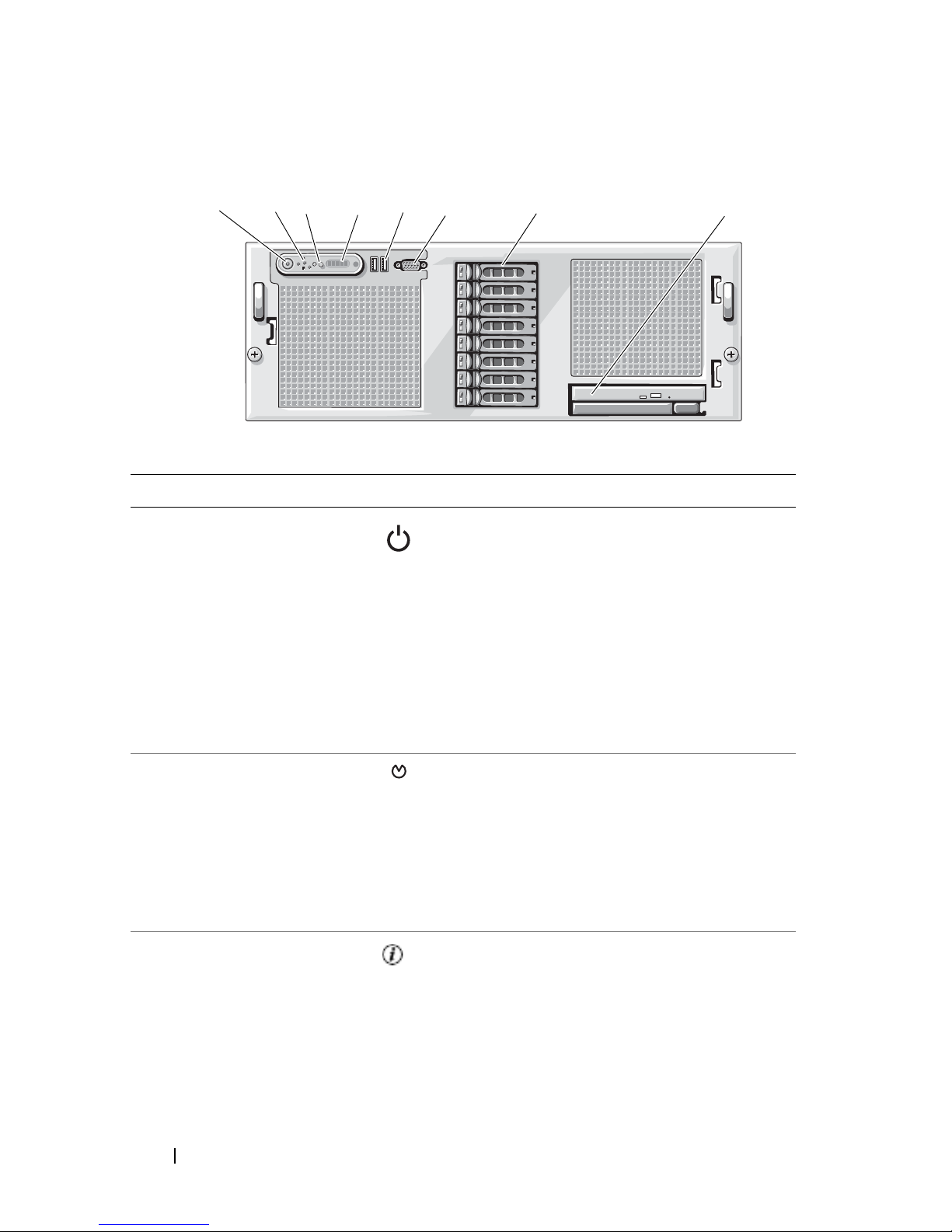
Figure 1-1. Front-Panel Features and Indicators
6
5
4
32
1
7
8
Table 1-2. Front-Panel Features and Connectors
Item Component Icon Description
1 Power-on indicator,
power button
The power button controls the DC power
supply output to the system.
NOTE: If you turn off the system using the
power button and the system is running an
ACPI-compliant operating system, the
system performs a graceful shutdown before
the power is turned off. If the system is not
running an ACPI-compliant operating
system, the power is turned off immediately
after the power button is pressed.
2 NMI button Used to troubleshoot software and device
driver errors when using certain operating
systems. This button can be pressed using
the end of a paper clip.
Use this button only if directed to do so by
qualified support personnel or by the
operating system's documentation.
3 System identification
button
The identification buttons on the front
and back panels can be used to locate a
particular system within a rack. When one
of these buttons is pushed, the blue system
status indicator on the front and back
blinks until one of the buttons is pushed
again.
14 About Your System
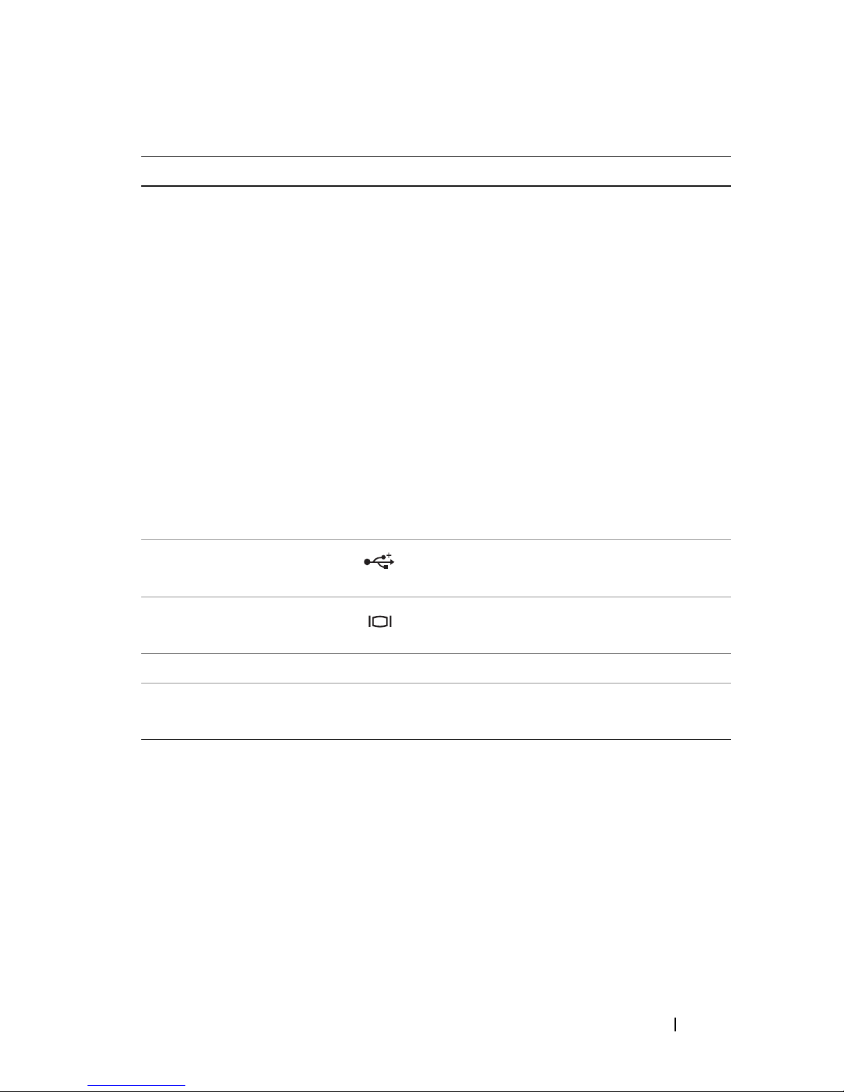
Table 1-2. Front-Panel Features and Connectors (continued)
Item Component Icon Description
4 LCD display Provides system ID, status information,
and system error messages.
The LCD display lights during normal
system operation. Both the systems
management software and the
identification buttons located on the front
and back of the system can cause the LCD
to flash blue to identify a particular system.
The LCD display lights amber when the
system needs attention due to a problem
with power supplies, fans, system
temperature, or hard drives.
NOTE: If the system is connected to AC
power and an error has been detected, the
LCD display lights amber regardless of
whether the system has been powered on.
5 USB connectors (2) Connects USB 2.0-compliant devices to
the system.
6 Video connector Connects a monitor to the system.
7 Hard drives (optional) Five 3.5" drives or eight 2.5" drives.
8 Optical drive
(optional)
Optional slimline optical drive
NOTE: DVD devices are data only.
About Your System 15
Hard-Drive Indicator Codes
1
2
The hard-drive carriers have two indicators—a drive-activity indicator and a
drive-status indicator. See Figure 1-2.
Figure 1-2. Hard-Drive Indicators
1 drive-status indicator (green
and amber) – requires
hardware RAID controller
2 green drive-activity indicator
Table 1-3 lists the drive indicator patterns for hard drives connected to a RAIDenabled controller card such as a PERC6i card. Different patterns are displayed
as drive events occur in the system. For example, if a hard drive fails, the "drive
failed" pattern appears. After the drive is selected for removal, the "drive being
prepared for removal" pattern appears, followed by the "drive ready for insertion
or removal" pattern. After the replacement drive is installed, the "drive being
prepared for operation" pattern appears, followed by the "drive online" pattern.
16 About Your System

Table 1-3. Hard-Drive Indicator Patterns for Drives Connected to a RAID Controller
Card
Condition Drive-Status Indicator Pattern
Identify drive/preparing
for removal
Drive ready for insertion or
removal
Drive predicted failure Blinks green, amber, and off.
Drive failed Blinks amber four times per second.
Drive rebuilding Blinks green slowly.
Drive online Steady green.
Rebuild halted Blinks green three seconds, amber three seconds, and
Blinks green two times per second
Off
NOTE: The drive status indicator remains off until all
hard drives are initialized after system power is applied.
Drives are not ready for insertion or removal during this
time.
off six seconds.
Back-Panel Features and Indicators
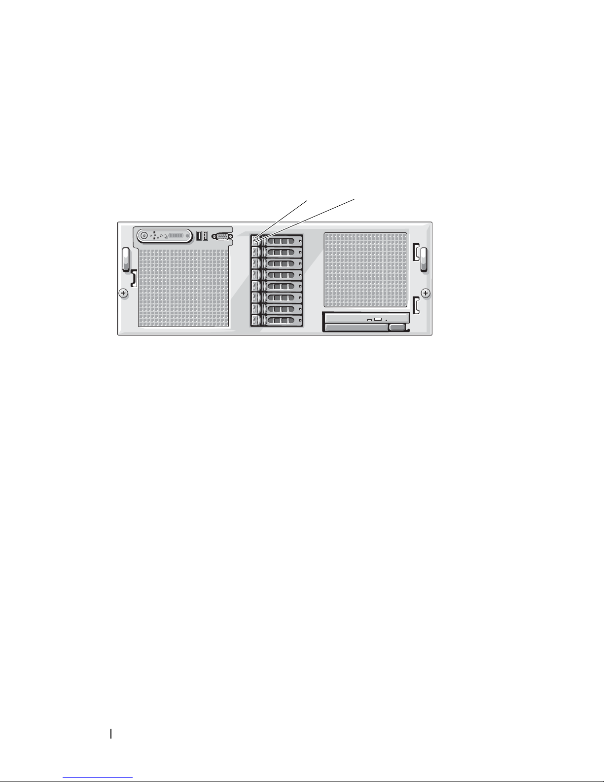
Figure 1-3 shows the controls, indicators, and connectors located on the
system's back panel.
About Your System 17
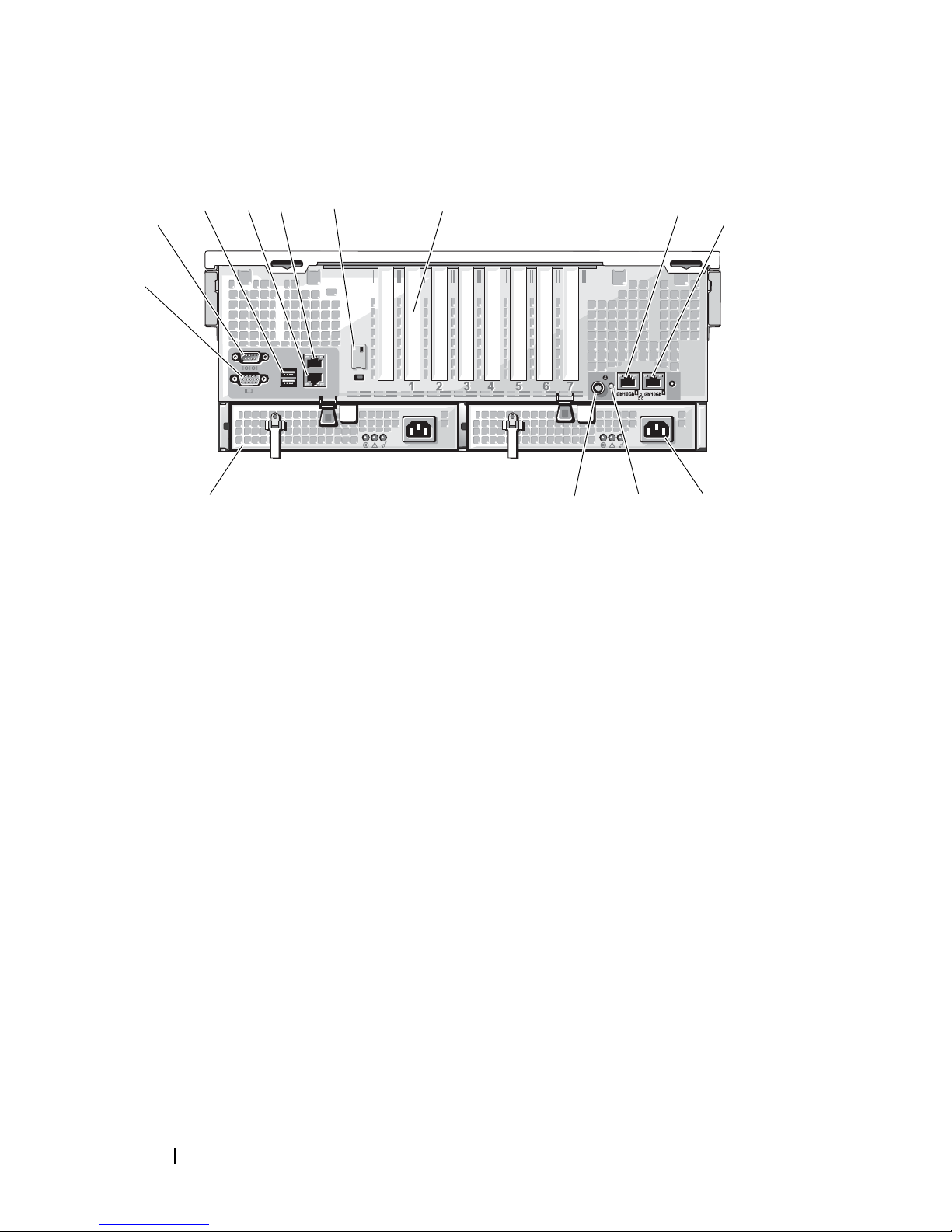
Figure 1-3. Back-Panel Features and Indicators
7
2
1
3
10
4
5
6
11
13
12
8
9
1 video connector 2 serial connector
3 USB connectors (2) 4 integrated NIC connector NIC2
5 integrated NIC connector NIC1 6 remote access controller (optional)
7 expansion-card slots (7) 8 integrated NIC connector NIC3
9 integrated NIC connector NIC4 10 power supply 2
11 system status indicator 12 system identification button
13 power supply 1
Connecting External Devices
When connecting external devices to your system, follow these guidelines:
• Most devices must be connected to a specific connector and device drivers
must be installed before the device operates properly. (Device drivers are
normally included with your operating system software or with the device
itself.) See the documentation that accompanied the device for specific
installation and configuration instructions.
• Always attach external devices while your system is turned off. Next, turn
on any external devices before turning on the system (unless the
documentation for the device specifies otherwise).
18 About Your System

For information about individual connectors, see "Jumpers and Connectors" on
page 173. For information about enabling, disabling, and configuring I/O ports
and connectors, see "Using the System Setup Program" on page 45.
Power Indicator Codes
The power button on the front panel controls the power input to the system's
power supplies. The power indicator can provide information on power status
(see
Figure 1-1
Table 1-4. Power Button Indicators
Indicator Function
On Indicates that power is supplied to the system and the system is
Flickering Power is supplied to the system but the system is powering up,
Off Indicates that no power is supplied to the system.
). Table 1-4 lists the power button indicator codes.
operational.
or shutting down.
The indicators on the power supplies show whether power is present or
whether a power fault has occurred (see Figure 1-4 and Table 1-5).
Table 1-5. Power Supply Indicators
Indicator Function
Power supply
status
Power supply
fault
AC line status Green indicates that a valid AC source is connected to the
Green indicates that the power supply is operational and
providing DC power to the system.
Amber indicates a problem with the power supply.
power supply and is operational.
About Your System 19
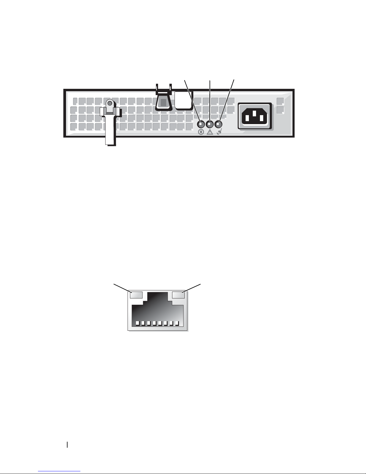
Figure 1-4. Power Supply Indicators
2
1
3
1
2
1 power supply status
(DC out is operational)
3 AC line status (AC in is operational)
2 power supply fault
NIC Indicator Codes
Each NIC on the system back panel has an indicator that provides
information on network activity and link status. See Figure 1-5. Table 1-6 lists
the NIC indicator codes.
Figure 1-5. NIC Indicators
1 link indicator 2 activity indicator
20 About Your System
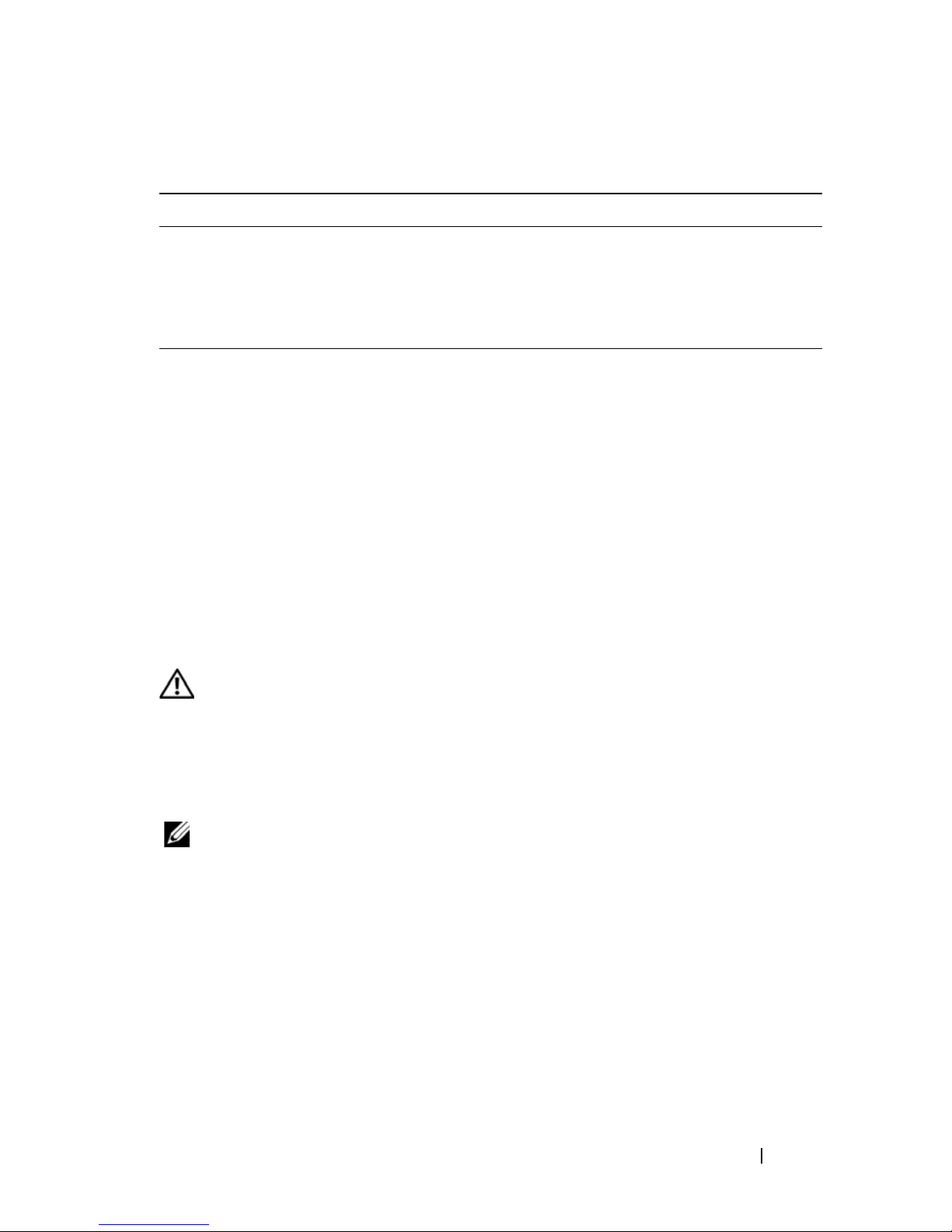
Table 1-6. NIC Indicator Codes
Indicator Indicator Code
Link and activity indicators are off The NIC is not connected to the network.
Link indicator is green The NIC is connected to a valid link partner on
the network.
Activity indicator is blinking amber Network data is being sent or received.
LCD Status Messages
The system's control panel LCD provides status messages to signify when the
system is operating correctly or when the system needs attention.
The LCD lights blue to indicate a normal operating condition, and lights
amber to indicate an error condition. The LCD scrolls a message that
includes a status code followed by descriptive text. Table 1-7 lists the LCD
status messages that can occur and the probable cause for each message. The
LCD messages refer to events recorded in the System Event Log (SEL). For
information on the SEL and configuring system management settings, see
the systems management software documentation.
CAUTION: Many repairs may only be done by a certified service technician. You
should only perform troubleshooting and simple repairs as authorized in your
product documentation, or as directed by the online or telephone service and
support team. Damage due to servicing that is not authorized by Dell is not covered
by your warranty. Read and follow the safety instructions that came with the
product.
NOTE: If your system fails to boot, press the System ID button for at least five
seconds until an error code appears on the LCD. Record the code, then see "Getting
Help" on page 181.
About Your System 21

Table 1-7. LCD Status Messages
Line 1
Message
N/A
Line 2
Message
SYSTEM NAME
Causes Corrective Actions
A 62-character string that
can be defined by the user
in the System Setup
program.
SYSTEM NAME
The
displays under the
following conditions:
• The system is powered
on.
• The power is off and
active POST errors are
displayed.
E1000 FAILSAFE,
Call Support
E1114 Temp Ambient Ambient system
temperature is out of
acceptable range.
This message is for
information only.
You can change the
system string in the
System Setup program.
See "Using the System
Setup Program" on
page 45.
See "Getting Help" on
page 181.
See "Troubleshooting
System Cooling
Problems" on page 157.
E1210 CMOS Batt CMOS battery is missing,
or the voltage is out of
acceptable range.
E1211 ROMB Batt RAID battery is either
missing, bad, or unable to
recharge due to thermal
issues.
E12
nn #
PwrGd Specified voltage
regulator has failed.
E1229 CPU # VCORE Processor # VCORE
voltage regulator has
failed.
22 About Your System
See "Troubleshooting the
System Battery" on
page 155.
Reseat the RAID battery.
See "Installing the SAS
RAID Controller Card
Battery" on page 115, and
"Troubleshooting System
Cooling Problems" on
page 157.
See "Getting Help" on
page 181.
See "Getting Help" on
page 181.

Table 1-7. LCD Status Messages (continued)
Line 1
Message
Line 2
Message
Causes Corrective Actions
E122A CPU # VTT Processor # VTT voltage
has exceeded the
allowable voltage range
E122D CPU # VDDIO Processor # VDDIO
voltage has exceeded the
allowable voltage range
E122E CPU # VDDA Processor # VDDA
voltage has exceeded the
allowable voltage range
E122F 2.5V PwrGd 2.5V voltage regulator has
failed.
E1231 1.2V HTCORE
PwrGd
E1232 VDD 12V PS#
PwrGd
1.2V HTCORE voltage
regulator has failed.
The specified power
supply has failed or has
been removed from the
bay while the system
was on.
See "Getting Help" on
page 181.
See "Getting Help" on
page 181.
See "Getting Help" on
page 181.
See "Getting Help" on
page 181.
See "Getting Help" on
page 181.
If removed, reinsert the
power supply into the bay
and reconnect to power.
For component failures,
see "Getting Help" on
page 181.
E123B LOM Mezz
PwrGd
Voltage regulator for the
NIC daughter card has
failed.
E123C Planar LOM
PwrGd
Voltage regulator for the
integrated NIC has failed.
E1310 RPM Fan ## RPM of specified cooling
fan is out of acceptable
operating range.
Recycle power to the
system or clear the SEL. If
the problem persists, see
"Getting Help" on
page 181.
Recycle power to the
system or clear the SEL. If
the problem persists, see
"Getting Help" on
page 181.
See "Troubleshooting
System Cooling
Problems" on page 157.
About Your System 23

Table 1-7. LCD Status Messages (continued)
Line 1
Message
Line 2
Message
E1313 Fan
Redundancy
E1414 CPU #
Thermtrip
Causes Corrective Actions
One or more cooling fans
has failed. Cooling fan
redundancy has been lost.
Specified microprocessor
is out of acceptable
temperature range and
has halted operation.
See "Troubleshooting
System Cooling
Problems" on page 157.
See "Troubleshooting
System Cooling
Problems" on page 157. If
the problem persists,
ensure that the
microprocessor heat sinks
are properly installed. See
"Troubleshooting the
Microprocessors" on
page 167.
NOTE: The LCD continues
to display this message
until the system’s power
cord is disconnected and
reconnected to the AC
power source, or the SEL
is cleared using either
Server Assistant or the
BMC Management Utility.
See the Dell OpenManage
Baseboard Management
Controller User’s Guide for
information about these
utilities.
E1418 CPU #
Presence
24 About Your System
Specified processor is
missing or bad, or the
system is in an
unsupported
configuration.
See "Troubleshooting the
Microprocessors" on
page 167.

Table 1-7. LCD Status Messages (continued)
Line 1
Message
Line 2
Message
Causes Corrective Actions
E141C CPU Mismatch Processors are in an
unsupported
configuration.
E141F CPU Protocol The system BIOS has
reported a processor
protocol error.
E1420 CPU Bus PERR The system BIOS has
reported a processor bus
parity error.
E1421 CPU Init The system BIOS has
reported a processor
initialization error.
Ensure that your
processors match and
conform to the type
described in the
Microprocessor Technical
Specifications outlined in
your system’s Getting
Started Guide.
See "Getting Help" on
page 181.
See "Getting Help" on
page 181.
See "Getting Help" on
page 181.
E1422 CPU Machine
Chk
The system BIOS has
reported a machine check
error.
E1610 PS # Missing Specified power supply is
improperly installed or
removed.
E1614 PS # Status Specified power supply is
improperly installed or
faulty.
E1618 PS #
Predictive
Power supply voltage is
out of acceptable range;
specified power supply is
improperly installed or
faulty.
See "Getting Help" on
page 181.
See "Troubleshooting
Power Supplies" on
page 156.
See "Troubleshooting
Power Supplies" on
page 156.
See "Troubleshooting
Power Supplies" on
page 156.
About Your System 25

Table 1-7. LCD Status Messages (continued)
Line 1
Message
Line 2
Message
E161C PS # Input
Lost
E1620 PS # Input
Range
E1624 PS
Redundancy
Causes Corrective Actions
Power source for specified
power supply is
unavailable, or out of
acceptable range.
Check the AC power
source for the specified
power supply. If problem
persists, see
"Troubleshooting Power
Supplies" on page 156.
Power source for specified
power supply is
unavailable, or out of
acceptable range.
Check the AC power
source for the specified
power supply. If problem
persists, see
"Troubleshooting Power
Supplies" on page 156.
Power supply redundancy
has been lost. If the
remaining power supply
See "Troubleshooting
Power Supplies" on
page 156.
fails the system will shut
down.
E1625 PS AC
Current
E1710 I/O Channel
Chk
E1711 PCI PERR B##
D## F##
PCI PERR
Slot #
Power source is out of
acceptable range.
The system BIOS has
reported an I/O channel
check error.
The system BIOS has
reported a PCI parity
error on a component
that resides in PCI
configuration space at
bus ##, device ##,
function ##.
The system BIOS has
reported a PCI parity
error on a component
that resides in PCI slot #.
Check the AC power
source.
See "Getting Help" on
page 181.
Remove and reseat the
specified PCI expansion
card. If the problem
persists, see
"Troubleshooting
Expansion Cards" on
page 166. If
troubleshooting does not
resolve the problem, see
"Getting Help" on
page 181.
26 About Your System

Table 1-7. LCD Status Messages (continued)
Line 1
Message
E1712 PCI SERR B##
Line 2
Message
D## F##
PCI SERR
Slot #
Causes Corrective Actions
The system BIOS has
reported a PCI system
error on a component
that resides in PCI
configuration space at
bus ##, device ##,
function ##.
The system BIOS has
reported a PCI system
error on a component
that resides in slot #.
E1714 Unknown Err The system BIOS has
determined that there has
been an error in the
system, but is unable to
determine its origin.
E171F PCIE Fatal
Err B## D##
F##
PCIE Fatal
Err Slot #
The system BIOS has
reported a PCIe fatal error
on a component that
resides in PCI
configuration space at
bus ##, device ##,
function ##.
The system BIOS has
reported a PCIe fatal error
on a component that
resides in slot #.
Remove and reseat the
specified PCI expansion
card. If the problem
persists, see
"Troubleshooting
Expansion Cards" on
page 166. If
troubleshooting does not
resolve the problem, see
"Getting Help" on
page 181.
See "Getting Help" on
page 181.
Remove and reseat the
specified PCI expansion
card. If the problem
persists, see
"Troubleshooting
Expansion Cards" on
page 166. If
troubleshooting does not
resolve the problem, see
"Getting Help" on
page 181.
E1810 HDD ## Fault Specified hard drive has a
E1811 HDD ## Rbld
Abrt
fault.
Specified hard drive has
ended rebuild before
completion.
See "Troubleshooting a
Hard Drive" on page 161.
See "Troubleshooting a
Hard Drive" on page 161.
About Your System 27

Table 1-7. LCD Status Messages (continued)
Line 1
Message
E1812 HDD ##
Line 2
Message
Removed
Causes Corrective Actions
Specified hard drive has
been removed from the
system.
E1914 DRAC5 Conn2
Cbl
DRAC 5 cable is missing
or unseated.
E1A14 SAS Cable A SAS cable A is unseated,
missing, or bad.
E1A15 SAS Cable B SAS cable B is unseated,
missing, or bad.
E1A1C LOM Mezz
Missing
NIC daughter card is
missing.
Information only.
Reconnect the cable. See
"RAC Card" on page 86.
Check the cable
connection to the SAS
backplane. See "SAS
Backplane Board
Connectors" on page 178.
Check the cable
connection to the SAS
backplane. See "SAS
Backplane Board
Connectors" on page 178.
Install or reseat the NIC
daughter card.
E2010 No Memory No memory is installed in
the system.
E2011 Mem Config
Err
Memory detected, but is
not configurable. Error
detected during memory
configuration.
E2012 Unusable
Memory
Memory is configured,
but not usable. Memory
subsystem failure.
Install memory modules.
See "System Memory" on
page 94.
Check the memory
configuration and
reinstall the memory
modules if necessary. See
"System Memory" on
page 94.
See "Troubleshooting
System Memory" on
page 158.
See "Troubleshooting
System Memory" on
page 158.
28 About Your System

Table 1-7. LCD Status Messages (continued)
Line 1
Message
E2013 Shadow BIOS
E2014 CMOS Fail CMOS failure. CMOS
Line 2
Message
Fail
Causes Corrective Actions
The system BIOS failed
to copy its flash image
into memory.
See "Troubleshooting
System Memory" on
page 158.
See "Getting Help" on
RAM not functioning
page 181.
properly.
E2015 DMA
Controller
E2016 Int
Controller
DMA controller failure. See "Getting Help" on
page 181.
Interrupt controller
failure.
See "Getting Help" on
page 181.
E2017 Timer Fail Timer refresh failure. See "Getting Help" on
page 181.
E2018 Prog Timer Programmable interval
timer error.
See "Getting Help" on
page 181.
E2019 Parity Error Parity error. See "Getting Help" on
page 181.
E201A SIO Err SIO failure. See "Getting Help" on
page 181.
E201B Kybd
Controller
E201C SMI Init System management
Keyboard controller
failure.
interrupt (SMI)
See "Getting Help" on
page 181.
See "Getting Help" on
page 181.
initialization failure.
E201D Shutdown
Test
E201E POST Mem
Test
BIOS shutdown test
failure.
BIOS POST memory test
failure.
See "Getting Help" on
page 181.
See "Troubleshooting
System Memory" on
page 158. If problem
persists, see "Getting
Help" on page 181.
About Your System 29

Table 1-7. LCD Status Messages (continued)
Line 1
Message
Line 2
Message
Causes Corrective Actions
E201F DRAC Config Remote access controller
(RAC) configuration
failure.
E2020 CPU Config CPU configuration
failure.
E2021 Memory
Population
Incorrect memory
configuration. Memory
population order
incorrect.
E2022 POST Fail General failure after
video.
Check screen for specific
error messages. Ensure
that the RAC card and
cables are properly seated.
See "RAC Card" on
page 86. If problem
persists, see your RAC
documentation.
Check screen for specific
error messages.
Check screen for specific
error messages. See
"Troubleshooting System
Memory" on page 158.
Check screen for specific
error messages.
E2110 MBE DIMM ##
& ##
E2111 SBE Log
Disable DIMM
##
One of the DIMMs in the
set implicated by "## &
##" has had a memory
multi-bit error (MBE).
The system BIOS has
disabled memory singlebit error (SBE) logging,
and will not resume
logging further SBEs until
the system is rebooted.
"##" represents the
DIMM implicated by the
BIOS.
See "Troubleshooting
System Memory" on
page 158.
See "Troubleshooting
System Memory" on
page 158.
30 About Your System
 Loading...