

Dell PowerEdge H730P User Manual

Dell PowerEdge RAID Controller (PERC)
H730P
For Dell PowerEdge R920 Systems User’s
Guide
Regulatory Model: UCPA-901 and UCPB-900

Notes, Cautions, and Warnings
NOTE: A NOTE indicates important information that helps you make better use of your computer.
CAUTION: A CAUTION indicates either potential damage to hardware or loss of data and tells you
how to avoid the problem.
WARNING: A WARNING indicates a potential for property damage, personal injury, or death.
Copyright © 2014 Dell Inc. All rights reserved. This product is protected by U.S. and international copyright and
intellectual property laws. Dell™ and the Dell logo are trademarks of Dell Inc. in the United States and/or other
jurisdictions. All other marks and names mentioned herein may be trademarks of their respective companies.
2014 - 04
Rev. A01

Contents
1 Overview.................................................................................................................... 11
Supported Operating Systems............................................................................................................ 12
Getting Started With Your PERC Card................................................................................................ 12
Related Documentation...................................................................................................................... 12
2 Features..................................................................................................................... 15
T10 Protection Information.................................................................................................................15
Enabling T10 PI.............................................................................................................................. 15
Disabling T10 PI............................................................................................................................. 16
Secure Firmware Update.....................................................................................................................16
Improved RAID 10 Configuration........................................................................................................16
4KB Block Size Disk Drives..................................................................................................................16
Physical Disk Power Management......................................................................................................16
Configured Spin Down Delay........................................................................................................17
Types Of Virtual Disk Initialization.......................................................................................................17
Full Initialization............................................................................................................................. 17
Fast Initialization.............................................................................................................................17
Background Initialization.....................................................................................................................18
Consistency Checks............................................................................................................................18
Disk Roaming.......................................................................................................................................18
Using Disk Roaming.......................................................................................................................19
FastPath................................................................................................................................................19
Virtual Disk Migration.......................................................................................................................... 19
Migrating Virtual Disks...................................................................................................................20
Virtual Disk Write Cache Policies........................................................................................................20
Conditions Under Which Write-Back Is Employed......................................................................20
Conditions Under Which Forced Write-Back With No Battery Is Employed.............................. 21
Virtual Disk Read Cache Policies.........................................................................................................21
Reconfiguration Of Virtual Disks.........................................................................................................21
Fault Tolerance....................................................................................................................................23
The SMART Feature....................................................................................................................... 23
Patrol Read.................................................................................................................................... 24
Physical Disk Failure Detection.....................................................................................................25
Using Persistent Hot Spare Slots...................................................................................................25
Physical Disk Hot Swapping..........................................................................................................25
Using Replace Member And Revertible Hot Spares.....................................................................25
Controller Cache Preservation..................................................................................................... 26
Non-RAID Disks Support.................................................................................................................... 26

Creating A Non-RAID Disk............................................................................................................26
3 Deploying The PERC Card.................................................................................... 27
PERC H730P Card Features................................................................................................................ 27
Removing The PERC H730P Card......................................................................................................28
Installing The PERC H730P Card........................................................................................................29
Cabling The PERC H730P Card..........................................................................................................30
4 Driver Installation...................................................................................................33
Pre-Installation Requirements For Windows Driver Installation....................................................... 33
Creating The Device Driver Media For Windows Driver Installation.................................................33
Downloading Drivers From The Dell Systems Service And Diagnostic Tools Media For
Windows........................................................................................................................................ 34
Downloading Drivers From The Dell Support Website For Windows.........................................34
Installing The Driver During a Windows Server 2008/2008 R2/2012 Installation......................34
Installing Windows Server 2008/2008 R2/2012 For A New RAID Controller.............................35
Updating Existing Windows Server 2008/2008 R2/2012............................................................ 35
Updating The Linux Driver.................................................................................................................. 36
Installing Or Updating The RPM Driver Package With DKMS Support........................................36
Installing Or Updating The RPM Driver Package With KMOD Support.......................................36
Installing Or Updating The RPM Driver Package With KMP Support...........................................37
5 Management Applications For PERC Cards.....................................................39
Comprehensive Embedded Management ........................................................................................ 39
Dell OpenManage Storage Management...........................................................................................39
BIOS Configuration Utility.................................................................................................................. 40
Entering The BIOS Configuration Utility...................................................................................... 40
Exiting The Configuration Utility.................................................................................................. 40
Menu Navigation Controls............................................................................................................ 41
Setting Up Virtual Disks.................................................................................................................42
Virtual Disk Management....................................................................................................................44
Creating Virtual Disks....................................................................................................................44
Selecting Virtual Disk Parameters.................................................................................................45
Initializing Virtual Disks..................................................................................................................45
Checking Data Consistency......................................................................................................... 46
Running A Data Consistency Check.............................................................................................46
Importing Or Clearing Foreign Configurations Using The VD Mgmt Menu...............................46
Importing Or Clearing Foreign Configurations Using The Foreign Configuration View
Screen............................................................................................................................................ 47
Break Mirror...................................................................................................................................48
Managing Preserved Cache..........................................................................................................49
Managing Dedicated Hot Spares..................................................................................................50

Deleting Virtual Disks.....................................................................................................................51
Deleting Disk Groups.....................................................................................................................51
Clearing The Configuration...........................................................................................................51
BIOS Configuration Utility Menu Options..........................................................................................52
Virtual Disk Management.............................................................................................................. 52
Virtual Disk Actions........................................................................................................................54
Physical Disk Management (PD Mgmt).........................................................................................55
Physical Disk Actions.....................................................................................................................55
Rebuild...........................................................................................................................................56
Controller Management (Ctrl Mgmt)............................................................................................56
Controller Management Actions.................................................................................................. 56
Foreign Configuration View.......................................................................................................... 57
Physical Disk Management.................................................................................................................58
Setting LED Blinking...................................................................................................................... 58
Creating Global Hot Spares.......................................................................................................... 58
Removing Global Or Dedicated Hot Spares................................................................................ 58
Replacing An Online Physical Disk............................................................................................... 59
Restrictions and Limitations..........................................................................................................59
Stopping Background Initialization...............................................................................................59
Performing A Manual Rebuild Of An Individual Physical Disk.....................................................60
Controller Management..................................................................................................................... 60
Enabling Boot Support..................................................................................................................60
Enabling Boot Support For A BIOS-Enabled Controller.............................................................. 61
Enabling BIOS Stop On Error........................................................................................................ 61
Disabling BIOS Stop On Error....................................................................................................... 61
Enabling Auto Import.................................................................................................................... 61
Disabling Auto Import................................................................................................................... 62
Restoring Factory Default Settings............................................................................................... 62
UEFI RAID Configuration Utility..........................................................................................................62
Entering The UEFI RAID Configuration Utility..............................................................................62
Configuration Options.................................................................................................................. 63
Controller Management Menu..................................................................................................... 63
Virtual Disk Management..............................................................................................................64
Physical Disk Management Menu.................................................................................................64
Enclosure Management................................................................................................................64
6 Security Key And RAID Management................................................................ 65
Security Key Implementation..............................................................................................................65
Security Key Management In The BIOS Configuration Utility...........................................................65
Local Key Management (LKM)...................................................................................................... 65
Creating A Security Key.................................................................................................................66
Changing The Security Key...........................................................................................................66

Deleting A Security Key................................................................................................................. 67
Creating Secured Virtual Disks......................................................................................................67
Securing Pre-Existing Virtual Disks...............................................................................................67
Importing Or Clearing Secured Foreign Configurations And Secure Disk Migration................ 68
Instant Secure Erase......................................................................................................................69
7 Troubleshooting......................................................................................................71
BIOS Configuration Utility Error Messages.........................................................................................71
Discovery Error Message............................................................................................................... 71
Extra Enclosure Error Message......................................................................................................71
Missing Disks In Virtual Disk Error Message..................................................................................71
Previous Configuration Of Disks Removed Error Message......................................................... 72
Missing Virtual Disks Error Message..............................................................................................72
Dirty Cache Data Error Message...................................................................................................72
BIOS Disabled Error Message........................................................................................................73
Drive Configuration Changes Error Message...............................................................................73
Adapter At Baseport Not Responding Error Message.................................................................. 73
Offline Or Missing Virtual Drives With Preserved Cache Error Message.....................................74
Virtual Disks Offline Error Message...............................................................................................74
Virtual Disks Degraded Error Message..........................................................................................74
Virtual Disks Partially Degraded Error Message............................................................................74
Memory Or Battery Problem Error Message................................................................................ 75
Firmware Fault State Error Message............................................................................................. 75
Foreign Configuration Found Error Message...............................................................................75
Foreign Configuration Not Found In <Ctrl> <R> Error Message................................................. 75
Previous Configuration Cleared Or Missing Error Message........................................................ 76
Invalid SAS Topology Detected Error Message............................................................................76
Configured Disks Removed Or Not Accessible Error Message...................................................76
Degraded State Of Virtual Disks..........................................................................................................76
Memory Errors..................................................................................................................................... 77
Preserved Cache State........................................................................................................................ 77
Security Key Errors...............................................................................................................................77
Secured Foreign Import Errors......................................................................................................77
Failure to Select Or Configure Non Self-Encrypting Disks (Non-SED)....................................... 77
Failure To Delete Security Key...................................................................................................... 78
Failure To Instant Secure Erase Task On Physical Disks.............................................................. 78
General Issues..................................................................................................................................... 78
PERC Card Has Yellow Bang In Device Manager.........................................................................78
PERC Card Not Seen In Device Manager..................................................................................... 78
Physical Disk Issues............................................................................................................................. 78
Physical Disk In Failed State.......................................................................................................... 78
Unable to Rebuild A Fault Tolerant Virtual Disk........................................................................... 79

Fatal Error Or Data Corruption Reported.....................................................................................79
Physical Disk Displayed As Blocked..............................................................................................79
Multiple Disks Become Inaccessible.............................................................................................79
Rebuilding A Failed Physical Disk................................................................................................. 80
Virtual Disk Fails During Rebuild Using A Global Hot Spare........................................................80
Virtual Disk Fails During Rebuild Using A Dedicated Hot Spare..................................................80
Physical Disk Fails During Reconstruction On Redundant Virtual Disk...................................... 80
Virtual Disk Fails Rebuild Using A Dedicated Hot Spare..............................................................80
Physical Disk Takes A Long Time To Rebuild.............................................................................. 80
SMART Errors....................................................................................................................................... 81
Smart Error Detected On A Physical Disk In A Redundant Virtual Disk.......................................81
Smart Error Detected On A Physical Disk In A Non-Redundant Virtual Disk..............................81
Replace Member Errors.......................................................................................................................81
Source Disk Fails During Replace Member Operation................................................................ 82
Target Disk Fails.............................................................................................................................82
General Disk Fails.......................................................................................................................... 82
Linux Operating System Errors...........................................................................................................82
Virtual Disk Policy Is Assumed As Write-Through Error Message...............................................82
Driver Does Not Auto-Build Into A New Kernel...........................................................................83
Unable To Register SCSI Device Error Message.......................................................................... 83
Disk Carrier LED Indicators.................................................................................................................83
8 Using PERC CLI....................................................................................................... 85
Using CLI Commands From Windows Command Prompts............................................................. 85
Using CLI Commands From Linux..................................................................................................... 85
PERC CLI Commands Overview.........................................................................................................85
Checking Controller Availability......................................................................................................... 86
SyntaxDescription......................................................................................................................... 86
Result............................................................................................................................................. 86
Displaying Controllers.........................................................................................................................87
SyntaxDescription..........................................................................................................................87
Result............................................................................................................................................. 87
Displaying Free Space Information.....................................................................................................87
SyntaxDescription..........................................................................................................................87
Result............................................................................................................................................. 87
Displaying Disk 1 Information............................................................................................................. 87
SyntaxDescription..........................................................................................................................87
Result............................................................................................................................................. 88
Displaying Controller, Virtual Disk, And Drivers Information............................................................ 88
SyntaxDescription......................................................................................................................... 88
Result............................................................................................................................................. 88
Checking For Preserved Cache .........................................................................................................89

SyntaxDescription......................................................................................................................... 89
Result.............................................................................................................................................90
Deleting Preserved Cache .................................................................................................................90
SyntaxDescription......................................................................................................................... 90
Result.............................................................................................................................................90
Displaying Expansion Information .................................................................................................... 90
SyntaxDescription......................................................................................................................... 90
Result.............................................................................................................................................90
Displaying Foreign Configuration.......................................................................................................91
SyntaxDescription..........................................................................................................................91
Result..............................................................................................................................................91
Importing Foreign Configuration........................................................................................................91
SyntaxDescription..........................................................................................................................91
Result..............................................................................................................................................91
Displaying BBU Information................................................................................................................91
SyntaxDescription..........................................................................................................................91
Result............................................................................................................................................. 92
Displaying Physical Drive Details For The Specified Slot In The Controller......................................93
SyntaxDescription......................................................................................................................... 93
Result............................................................................................................................................. 94
Displaying Boot Drive For The Controller..........................................................................................95
SyntaxDescription..........................................................................................................................95
Result............................................................................................................................................. 95
Setting Virtual Drive As Boot Drive..................................................................................................... 95
SyntaxDescription..........................................................................................................................95
Result............................................................................................................................................. 96
Locating A Drive..................................................................................................................................96
SyntaxDescription......................................................................................................................... 96
Result............................................................................................................................................. 96
Stopping A locate Operation..............................................................................................................96
SyntaxDescription......................................................................................................................... 96
Result............................................................................................................................................. 96
9 Appendix: RAID Description................................................................................ 97
Summary Of RAID Levels.................................................................................................................... 97
RAID Terminology............................................................................................................................... 97
Disk Striping................................................................................................................................... 97
Disk Mirroring................................................................................................................................ 98
Spanned RAID Levels.................................................................................................................... 98
Parity Data..................................................................................................................................... 98
10 Getting Help.........................................................................................................101

Contacting Dell..................................................................................................................................101
Documentation Feedback.................................................................................................................101
Locating Your System Service Tag....................................................................................................101

10

1
Overview
The Dell PowerEdge RAID Controller (PERC) H730P storage controller card:
• Complies with serial-attached SCSI (SAS) 3.0 providing up to 12 Gb/sec throughput.
• Supports Dell-qualified serial-attached SCSI (SAS) hard drives, SATA hard drives, and solid-state drives
(SSDs).
NOTE: Mixing 512–byte native and 512–byte emulated drives are allowed. But mixing 512–byte
and 4KB native block size drives are not allowed.
NOTE: Mixing drives of different speeds (7,200 rpm, 10,000 rpm, or 15,000 rpm) and bandwidth
(3 Gbps, 6 Gbps, or 12 Gbps) while maintaining the same drive type (SAS or SATA) and
technology (HDD or SSD) is supported.
• Supports RAID levels 0, 1, 5, 6, 10, 50, and 60.
• Provides reliability, high performance, and fault-tolerant disk subsystem management.
• Supports operating system installation on 4KB drives using Unified Extensible Firmware Interface
(UEFI).
NOTE: BIOS does not support operating system installation on 4KB drives.
The following table provides PERC H730P hardware specifications.
Table 1. Hardware Specifications for PERC H730P
Specification PERC H730P
RAID levels 0, 1, 5, 6, 10, 50, 60
Enclosures per port Not Applicable
Processor Dell Adapter SAS RAID-on- Chip, 8-port with LSI 3108
chipset
Backup Battery Unit (BBU) Yes
Non-volatile cache Yes
Cache memory 2 GB DDR3 1866 Mhz
Cache function Write Back, Write Through, No Read Ahead, and Read
Ahead
Maximum number of virtual disks per disk
group
16
Online capacity expansion Yes
Dedicated and global hot spares Yes
Hot swap devices supported Yes
Hardware XOR engine Yes
11

Supported Operating Systems
The PERC H730P card supports the following operating systems:
• Microsoft Windows Server 2012
• Microsoft Windows Server 2012 R2
• Microsoft Windows Server 2008 including Hyper-V virtualization
• Microsoft Windows Server 2008 R2 and later
• Microsoft Windows Server 2008 R2 SP1
• VMware ESXi 5.0 Update 2
• VMware ESXi 5.1 Update 1
• VMware ESXi 5.5
• VMware vSphere 6.0
• Red Hat Enterprise Virtualization
• Red Hat Enterprise Linux version 6.4 (32-bit and 64-bit)
• Red Hat Enterprise Linux version 6.5 (64-bit)
• Red Hat Enterprise Linux 6.5 for HPC Compute Node
• Red Hat Enterprise Virtualization 4.0 (64-bit)
• SUSE Linux Enterprise Server version 10 SP4 (64-bit)
• SUSE Linux Enterprise Server version 11 SP3 (64-bit)
• Citrix XenServer 6.x
NOTE: For the latest list of supported operating systems and driver installation instructions, see
the system documentation at dell.com/support/manuals. For specific operating system service
pack requirements, see the Drivers and Downloads section at dell.com/support/manuals.
Getting Started With Your PERC Card
1. Unpack your PERC H730P card.
2. Cable the PERC card inside the Dell PowerEdge R920 system. See Deploying The PERC Card.
3. Boot to the operating system.
4. Download and install the drivers and firmware for the PERC H730P card. See Driver Installation.
5. Create virtual disks and specify RAID levels for your hard drives using any of the utilities mentioned
below:
• BIOS Configuration, see BIOS Configuration Utility
• PERC CLI, see Using PERC CLI
• OMSS, see Dell OpenManage Storage Management
Related Documentation
NOTE: For all storage controllers and PCIe SSD documents, go to dell.com/
storagecontrollermanuals.
NOTE: For all Dell OpenManage documents, go to dell.com/openmanagemanuals.
NOTE: For all operating system documents, go to dell.com/operatingsystemmanuals.
12

NOTE: For all PowerEdge documentation, go to dell.com/poweredgemanuals.
NOTE: For all PowerVault documentation, go to dell.com/powervaultmanuals.
Your product documentation includes, Dell PowerEdge RAID Controller (PERC) H730P User’s Guide For
Dell PowerEdge R920 Systems. The User’s Guide discusses features, installation, management, and
troubleshooting of PERC cards.
13

14

2
Features
PowerEdge RAID Controller (PERC) H730P card supports the following features:
• T10 Protection Information (PI)
• secure firmware update
• improved RAID 10 configuration
• 4KB block size disk drives
• physical disk power management
• types of virtual disk initialization
• consistency check
• disk roaming
• fast path
• virtual disk migration
• reconfiguration of virtual disks
• fault tolerance
• patrol read
• non-RAID disks support
T10 Protection Information
T10 Protection Information (PI) is an end-to-end data integrity feature of the PERC H730P card. When PI
is enabled, the PERC H730P provides additional protection against silent data corruption, and ensures
that incomplete and incorrect data do not overwrite good data.
Only Dell certified PI disks are supported.
NOTE: PI is not supported on the SAS disks with 512–byte native and 512–byte emulated block size
and SATA disks.
Enabling T10 PI
To enable T10 PI:
1. During host system boot, press <Ctrl> <R> to access the BIOs Configuration Utility.
The Virtual Disk Management screen is displayed in the BIOS Configuration Utility window.
If there is more than one controller, the main menu screen is displayed. Select a controller, and press
<Enter>. The Virtual Disk Management screen is displayed for the selected controller.
2. Use the arrow keys to highlight PERC H730P Adapter or Disk Group # .
3. Press <F2>.
The list of available actions is displayed.
4. Click Enable Data Protection.
15

Disabling T10 PI
To disable T10 PI:
1. Press <F2>.
The list of available actions is displayed.
2. Click Disable Data Protection.
Secure Firmware Update
This feature provides a cryptographic method of updating the firmware using RSA encryption-decryption
algorithm.
Only Dell certified firmware is supported on your PERC controller.
Improved RAID 10 Configuration
RAID 10 configuration has been simplified for easier management and deployment. Disks are selected in
mirrored pairs, and the user is no longer required to select the number of disks per span.
NOTE: An even number of drives is required to create RAID 10 virtual disks.
4KB Block Size Disk Drives
PERC H730P card supports 4KB block size disk drives, which enables you to efficiently use the storage
space.
NOTE: Mixing 512–byte native and 512–byte emulated drives in a virtual disk is allowed. But, mixing
512–byte and 4KB native block size drives in a virtual disk is not allowed.
Physical Disk Power Management
Physical disk power management is a power-saving feature of the PERC H730P card. The feature allows
disks to be spun down based on disk configuration and I/O activity. The feature is supported on all
rotating SAS and SATA disks and includes unconfigured, configured, and hot-spare disks. The physical
disk power management feature is disabled by default. The feature can be enabled in the Dell Open
Manage Storage Management application or Unified Extensible Firmware Interface (UEFI) RAID
Configuration utility. For more information, see the Dell OpenManage documentation at dell.com/
support/manuals.
There are four power-saving modes:
No Power
Savings
(default mode)
All power savings features are disabled.
Balanced
Power Savings
Spin down is enabled only for unconfigured and hot spare disks.
16

Maximum
Power Savings
Spin down is enabled for configured, unconfigured, and hot spare disks.
Customized
Power Savings
All power savings features are customizable. You can specify a Quality of Service
window during which the configured disks are excluded from spin-down.
Configured Spin Down Delay
NOTE: The Configured Spin Down Delay option is not applicable for the No Power Savings mode.
The amount of time to wait before spinning down disks can be set using Configured Spin Down Delay.
The minimum value of the timer is 30 minutes (default) and the maximum is one day. Disks are spun
down automatically and spun up when accessed. All disks are spun up on reboot.
NOTE: There is a delay in I/O operations when a configured disk is being spun up.
Types Of Virtual Disk Initialization
PERC H730P supports two types of virtual disk initialization:
• Full Initialization
• Fast Initialization
CAUTION: Initializing virtual disks erases files and file systems while keeping the virtual disk
configuration intact.
NOTE: The following initialization operations are not applicable for non-RAID disks.
Full Initialization
Performing a full initialization on a virtual disk overwrites all blocks and destroys any data that previously
existed on the virtual disk. Full initialization of a virtual disk eliminates the need for the virtual disk to
undergo a Background initialization (BGI). Full initialization can be performed after the virtual disk is
created.
During full initialization, the host cannot access the virtual disk. You can start a full initialization on a
virtual disk by using the Slow Initialize option in the Dell OpenManage storage management application.
For more information on using the BIOS Configuration Utility to perform a full initialization, see
Initializing Virtual Disks.
NOTE: Full initialization does not support RAID 6 virtual disks with the PI enabled. BGI runs instead.
NOTE: For better performance, you can perform full initialization on virtual disks. Full initialization
does not support RAID 6 and RAID 60 virtual disks with the PI feature enabled.
NOTE: If the system reboots during a full initialization, the operation aborts and a BGI begin on the
virtual disk.
Fast Initialization
A fast initialization on a virtual disk overwrites the first and last 8 MB of the virtual disk, clearing any boot
records or partition information. The operation takes only 2–3 seconds to complete, but it is followed by
17

BGI, which takes a longer time to complete. To perform a fast initialization using the BIOS Configuration
Utility, see Initializing Virtual Disks.
NOTE: Fast initialization does not support RAID 6 and RAID 60 virtual disks with the PI feature
enabled.
Background Initialization
Background Initialization (BGI) is an automated process that writes the parity or mirror data on newly
created virtual disks. BGI does not run on RAID 0 virtual disks. You can control the BGI rate in the Dell
OpenManage storage management application. Any change in the BGI rate does not take effect until the
next BGI run.
NOTE: BGI will run on RAID 0 virtual disks only with PI enabled.
NOTE: You cannot disable BGI permanently. If you cancel BGI, it automatically restarts within five
minutes. For information on stopping BGI, see
Stopping Background Initialization.
NOTE: Unlike full or fast initialization of virtual disks, background initialization does not clear data
from the physical disks.
NOTE: Consistency Check (CC)/BGI typically causes some loss in performance until the operation
completes.
NOTE: VD with PI will have a longer background initialization when compared to non-PI virtual
disks.
Consistency Check (CC) and BGI perform similar functions in that they both correct parity errors.
However, CC reports data inconsistencies through an event notification, but BGI does not. You can start
CC manually, but not BGI.
Consistency Checks
Consistency Check (CC) is a background operation that verifies and corrects the mirror or parity data for
fault tolerant virtual disks. It is recommended that you periodically run a consistency check on virtual
disks.
You can manually start a CC using the BIOS Configuration Utility or the Dell OpenManage storage
management application. You can schedule a CC to run on virtual disks using the Dell OpenManage
storage management application. To start a CC using the BIOS Configuration Utility, see Checking Data
Consistency .
NOTE: CC/BGI typically causes some loss in performance until the operation completes.
Consistency Check (CC) and BGI both correct parity errors. However, CC reports data inconsistencies
through an event notification, but BGI does not. You can start CC manually, but not BGI.
Disk Roaming
Disk roaming is moving the physical disks from one cable connection or backplane slot to another on the
same controller. The controller automatically recognizes the relocated physical disks and logically places
them in the virtual disks that are part of the disk group. You can perform disk roaming only when the
system is turned off.
18

CAUTION: Do not attempt disk roaming during RAID level migration (RLM) or online capacity
expansion (OCE). This causes loss of the virtual disk.
Using Disk Roaming
Perform the following steps to use disk roaming:
1. Turn off the power to the system, physical disks, enclosures, and system components.
2. Disconnect power cables from the system.
3. Move the physical disks to desired positions on the backplane or the enclosure.
4. Perform a safety check. Make sure the physical disks are inserted properly.
5. Turn on the system.
The controller detects the RAID configuration from the configuration data on the physical disks.
FastPath
FastPath is a feature that improves application performance by delivering high I/O per second (IOPs) for
the Solid State Drives (SSD). The Dell PowerEdge RAID Controller (PERC) H730P supports FastPath.
To enable FastPath on a virtual disk the Dell PowerEdge RAID Controller (PERC) H730P cache policies
need to be set to Write-Through and No Read Ahead. This enables FastPath to use the proper data path
through the controller based on command (read/write), IO size, and RAID type.
For small random workloads, like OLTP, a RAID 10 array provides high performance and for sequential
read dominate workloads, a RAID5 array provides high performance.
NOTE: Only IO block sizes smaller than virtual disk’s stripe size are eligible for FastPath.
NOTE: The Physical Disk Power Management feature is not applicable to FastPath-capable virtual
disks.
Virtual Disk Migration
The PERC H730P card supports migration of virtual disks from one controller to another without taking
the target controller offline. The controller can import RAID virtual disks in optimal, degraded, or partially
degraded states. You cannot import a virtual disk that is offline. Disk migration pointers:
• Supports migration of virtual disks from PERC H310, H710, H710P, and H810 to PERC H730P
• Supports migration of volumes created within PERC H730P
• Does not support migration from PERC H730P to H310, H710, H710P, H810
NOTE: The source controller must be offline prior to performing the disk migration.
NOTE: Disks cannot be migrated to older generations of the PERC cards.
NOTE: Importing secured virtual disks is supported as long as the appropriate Local Key
Management (LKM) is supplied or configured.
When a controller detects a configured physical disk, it flags the physical disk as foreign, and generates
an alert indicating that a foreign disk was detected.
19

CAUTION: Do not attempt disk migration during RLM or online capacity expansion (OCE). This
causes loss of the virtual disk.
Migrating Virtual Disks
To migrate virtual disks from PERC H710, H710P, or H810 to PERC H730P:
1. Turn off the system.
2. Move the physical disks from PERC H710, H710P, or H810 card to the PERC H730P card.
3. Boot the system and import the foreign configuration that is detected. You can do one of the
following:
• Press <F> to automatically import the foreign configuration.
• Enter the BIOS Configuration Utility and navigate to the Foreign Configuration View.
NOTE: For more information on accessing the BIOS Configuration Utility, see Entering The
BIOs Configuration Utility.
NOTE: For more information on Foreign Configuration View, see Foriegn Configuration View.
4. Exit the BIOS Configuration Utility and reboot the system.
5. Ensure that all the latest drivers for the PERC H710, H710P, or H810 card (available at dell.com/
support) are installed.
For more information, see Driver Installation.
Virtual Disk Write Cache Policies
The write cache policy of a virtual disk determines how the controller handles writes to the virtual disk.
The write cache policies are:
Write-Back The controller sends a data transfer completion signal to the host when the
controller cache has received all the data in a transaction. The controller then
writes the cached data to the storage device in the background.
NOTE: The default cache setting for virtual disks is Write-Back caching.
Write-Through The controller sends a data transfer completion signal to the host system when the
disk subsystem has received all the data in a transaction.
All RAID volumes are presented as Write-Through to the operating system
(Windows and Linux) independent of the actual write cache policy of the virtual
disk. The PERC cards manage the data in cache independently of the operating
system or any applications.
NOTE: Certain data patterns and configurations perform better with a Write-
Through cache policy.
NOTE: Use the Dell OpenManage storage management application or the BIOS Configuration
Utility to view and manage virtual disk cache settings.
Conditions Under Which Write-Back Is Employed
Write-Back caching is used under all conditions in which the battery is present and in good condition.
20

Conditions Under Which Forced Write-Back With No Battery Is Employed
CAUTION: It is recommended that you use a power backup system when forcing Write-Back to
ensure there is no loss of data if the system suddenly loses power.
Write-Back mode is available when you select Force WB with no battery. When Forced Write-Back
mode is selected, the virtual disk is in Write-Back mode even if the battery is not present.
Virtual Disk Read Cache Policies
The read policy of a virtual disk determines how the controller handles reads to that virtual disk. The read
policies are:
Always Read
Ahead
Allows the controller to read sequentially ahead of requested data and to store the
additional data in cache memory, anticipating that the data is required soon. This
speeds up reads for sequential data, but there is little improvement when accessing
random data.
No Read Ahead Disables the Read-Ahead capability.
Reconfiguration Of Virtual Disks
An online virtual disk can be reconfigured in ways that expands its capacity and/or change its RAID level.
NOTE: Spanned virtual disks such as RAID 10, 50, and 60 cannot be reconfigured.
NOTE: Reconfiguring Virtual Disks typically impacts disk performance until the reconfiguration
operation is complete.
Online Capacity Expansion (OCE) can be done in two ways:
• If there is a single virtual disk in a disk group and free space is available, the virtual disk’s capacity can
be expanded within that free space.
• If a virtual disk is created and it does not use the maximum size of the disk group, free space is
available.
Free space is also available when a disk group’s physical disks are replaced by larger disks using the
Replace Member feature. A virtual disk's capacity can also be expanded by performing an OCE operation
to add more physical disks.
RAID Level Migration (RLM) refers to changing a virtual disk’s RAID level. Both RLM and OCE can be done
at the same time so that a virtual disk can simultaneously have its RAID level changed and its capacity
increased. When a RLM/OCE operation is complete, a reboot is not required. The source RAID level
column indicates the virtual disk RAID level before the RLM/OCE operation and the target RAID level
column indicates the RAID level after the RLM/OCE operation.
NOTE: If the controller already contains the maximum number of virtual disks, you cannot perform
a RAID level migration or capacity expansion on any virtual disk.
NOTE: The controller changes the write cache policy of all virtual disks undergoing a RLM/OCE
operation to Write-Through until the RLM/OCE operation is complete.
21

See the following table for a list of RLM/OCE possibilities.
Table 2. RAID Level Migration
Source RAID
Level
Target RAID
Level
Number of
Physical Disks
(Beginning)
Number of
Physical Disks
(End)
Capacity
Expansion
Possible
Description
RAID 0 RAID 0 1 2 or more Yes Increases
capacity by
adding disks.
RAID 0 RAID 1 1 2 No Converts a
non-redundant
virtual disk into
a mirrored
virtual disk by
adding one
disk.
RAID 0 RAID 5 1 or more 3 or more Yes At least one
disk needs to
be added for
distributed
parity data.
RAID 0 RAID 6 1 or more 4 or more Yes At least two
disks need to
be added for
dual distributed
parity data.
RAID 1 RAID 0 2 2 or more Yes Removes
redundancy
while increasing
capacity.
RAID 1 RAID 5 2 3 or more Yes Maintains
redundancy
while doubling
capacity.
RAID 1 RAID 6 2 4 or more Yes Two disks
required to be
added for
distributed
parity data.
RAID 5 RAID 0 3 or more 3 or more Yes Converts to a
non-redundant
virtual disk and
reclaims disk
space used for
distributed
parity data.
22

Source RAID
Level
Target RAID
Level
Number of
Physical Disks
(Beginning)
Number of
Physical Disks
(End)
Capacity
Expansion
Possible
Description
RAID 5 RAID 5 3 or more 4 or more Yes Increases
capacity by
adding disks.
RAID 5 RAID 6 3 or more 4 or more Yes At least one
disk needs to
be added for
dual distributed
parity data.
RAID 6 RAID 0 4 or more 4 or more Yes Converts to a
non-redundant
virtual disk and
reclaims disk
space used for
distributed
parity data.
RAID 6 RAID 5 4 or more 4 or more Yes Removes one
set of parity
data and
reclaims disk
space used for
it.
RAID 6 RAID 6 4 or more 5 or more Yes Increases
capacity by
adding disks
NOTE: The total number of physical disks in a disk group cannot exceed 32. You cannot perform
RAID level migration and expansion on RAID levels 10, 50, and 60.
Fault Tolerance
The PERC H730P card supports the following:
• Self Monitoring and Reporting Technology (SMART)
• Patrol Read
• Physical disk failure detection
• Physical disk rebuild using hot spares
• Controller cache preservation
• Battery and non-volatile cache backup of controller cache to protect data
• Detection of batteries with low charge after boot up
The next sections describe some methods to achieve fault tolerance.
The SMART Feature
The SMART feature monitors certain physical aspects of all motors, heads, and physical disk electronics
to help detect predictable physical disk failures. Data on SMART-compliant physical disks can be
23

monitored to identify changes in values and determine whether the values are within threshold limits.
Many mechanical and electrical failures display some degradation in performance before failure.
A SMART failure is also referred to as predicted failure. There are numerous factors that are predicted
physical disk failures, such as a bearing failure, a broken read/write head, and changes in spin-up rate. In
addition, there are factors related to read/write surface failure, such as seek error rate and excessive bad
sectors.
NOTE: For detailed information on SCSI interface specifications, see t10.org and for detailed
information on SATA interface specifications, see t13.org.
Automatic Replace Member With Predicted Failure
A Replace Member operation can occur when there is a SMART predictive failure reporting on a physical
disk in a virtual disk. The automatic Replace Member is initiated when the first SMART error occurs on a
physical disk that is part of a virtual disk. The target disk needs to be a hot spare that qualifies as a rebuild
disk. The physical disk with the SMART error is marked as failed only after the successful completion of
the Replace Member. This prevents the array from reaching degraded state.
If an automatic Replace Member occurs using a source disk that was originally a hot spare (that was used
in a rebuild), and a new disk added for the Replace Member operation as the target disk, the hot spare
reverts to the hot spare state after a successful Replace Member operation.
NOTE: To enable the automatic Replace Member, use the Dell OpenManage storage management
application. For information on manual Replace Member, see Replacing An Online Physical Disks.
Patrol Read
The Patrol Read feature is designed as a preventative measure to ensure physical disk health and data
integrity. Patrol Read scans and resolves potential problems on configured physical disks. The Dell
OpenManage storage management application can be used to start Patrol Read and change its behavior.
The following is an overview of Patrol Read behavior:
• Patrol Read runs on all disks on the controller that are configured as part of a virtual disk, including
hot spares.
• Patrol Read does not run on physical disks that are not part of a virtual disk or are in Ready state.
• Patrol Read adjusts the amount of controller resources dedicated to Patrol Read operations based on
outstanding disk I/O. For example, if the system is busy processing I/O operation, then Patrol Read
uses fewer resources to allow the I/O to take a higher priority.
• Patrol Read does not run on any disks involved in any of the following operations:
– Rebuild
– Replace Member
– Full or Background Initialization
– CC
– RLM or OCE
NOTE: By default, Patrol Read automatically runs every seven days on configured SAS and SATA
hard drives. Patrol Read is not necessary on SSD and is disabled by default.
For more information on Patrol Read, see the Dell OpenManage documentation at dell.com/support/
manuals.
24

Physical Disk Failure Detection
Failed physical disks are detected and rebuilds automatically start to new disks that are inserted into the
same slot. Automatic rebuilds can also occur with hot spares. If you have configured hot spares, the
controllers automatically try to use them to rebuild failed physical disks.
Using Persistent Hot Spare Slots
NOTE: The persistent hot spare slot feature is disabled by default.
The PERC H730P card can be configured so that the system backplane or storage enclosure disk slots are
dedicated as hot spare slots. This feature can be enabled using the Dell OpenManage storage
management application.
Once enabled, any slots with hot spares configured automatically become persistent hot spare slots. If a
hot spare disk fails or is removed, a replacement disk that is inserted into the same slot automatically
becomes a hot spare with the same properties as the one it is replacing. If the replacement disk does not
match the disk protocol and technology, it does not become a hot spare.
For more information on persistent hot spares, see the Dell OpenManage documentation at dell.com/
support/manuals.
Physical Disk Hot Swapping
NOTE: To check if the backplane supports hot swapping, see the Owner’s Manual of your system.
Hot swapping is the manual replacement of a disk while the PERC H730P card is online and performing
their normal functions. The following requirements must be met before hot swapping a physical disk:
• The system backplane or enclosure must support hot swapping for the PERC H730P card to support
hot swapping.
• The replacement disk must be of the same protocol and disk technology. For example, only a SAS
hard drive can replace a SAS hard drive and only a SATA SSD can replace a SATA SSD.
Using Replace Member And Revertible Hot Spares
The Replace Member functionality allows a previously commissioned hot spare to revert to a usable hot
spare. When a disk failure occurs within a virtual disk, an assigned hot spare (dedicated or global) is
commissioned and begins rebuilding until the virtual disk is optimal. After the failed disk is replaced (in the
same slot) and the rebuild to the hot spare is complete, the controller automatically starts to copy data
from the commissioned hot spare to the newly-inserted disk. After the data is copied, the new disk is a
part of the virtual disk and the hot spare is reverted to being a ready hot spare. This allows hot spares to
remain in specific enclosure slots. While the controller is reverting the hot spare, the virtual disk remains
optimal.
NOTE: The controller automatically reverts a hot spare only if the failed disk is replaced with a new
disk in the same slot. If the new disk is not placed in the same slot, a manual Replace Member
operation can be used to revert a previously commissioned hot spare.
NOTE: A Replace Member operation typically causes a temporary impact to disk performance.
Once the operation completes, performance returns to normal.
25

Controller Cache Preservation
The controller is capable of preserving its cache in the event of a system power outage or improper
system shutdown. The PERC H730P controller is attached to a Battery Backup Unit (BBU) that provides
backup power during system power loss to preserve the controller's cache data.
Cache Preservation With NVC
The Non-Volatile Cache (NVC) module allows controller cache data to be stored indefinitely. If the
controller has data in the cache memory during a power outage or improper system shutdown, a small
amount of power from the battery is used to transfer the cache data to a non-volatile flash storage where
it remains until power is restored and the system is booted.
Recovering Cache Data
If a system power loss or improper system shutdown has occurred:
1. Restore the system power.
2. Boot the system.
3. To enter the BIOS Configuration Utility, select Managed Preserved Cache in the controller menu.
If there are no virtual disks listed, all preserved cache data has been written to the disk successfully.
Non-RAID Disks Support
By default, all the disks are in RAID capable unconfigured state. The user can also convert the RAID
capable disks to non-RAID disks using Management Utilities.
Creating A Non-RAID Disk
To create a non-RAID disk, perform the following steps in the BIOS Configuration Utility (<Ctrl> <R>):
1. In the Virtual Disk Mgmnt screen, use the arrow keys to highlight PERC H730P Adapter or Disk
Group #.
2. Press <F2>.
The list of available action is displayed.
3. Click Convert to Non-RAID.
The Convert RAID Capable Disks to Non-RAID window is displayed.
4. Press the down-arrow key to highlight an available physical disk.
5. Press the spacebar to select the disk.
NOTE: An X is displayed beside the selected physical disk(s).
6. Select OK.
26
3
Deploying The PERC Card
CAUTION: Many repairs may only be done by a certified service technician. You should only
perform troubleshooting and simple repairs as authorized in your product documentation, or as
directed by the online or telephone service and support team. Damage due to servicing that is
not authorized by Dell is not covered by your warranty. Read and follow the safety instructions
that came with the system.
NOTE: For information on removing and reinstalling system parts, see the Dell PowerEdge R920
Owner's Manual at dell.com/poweredgemanuals.
This section provides a set of high level installation and removal instructions for the PERC H730P card.
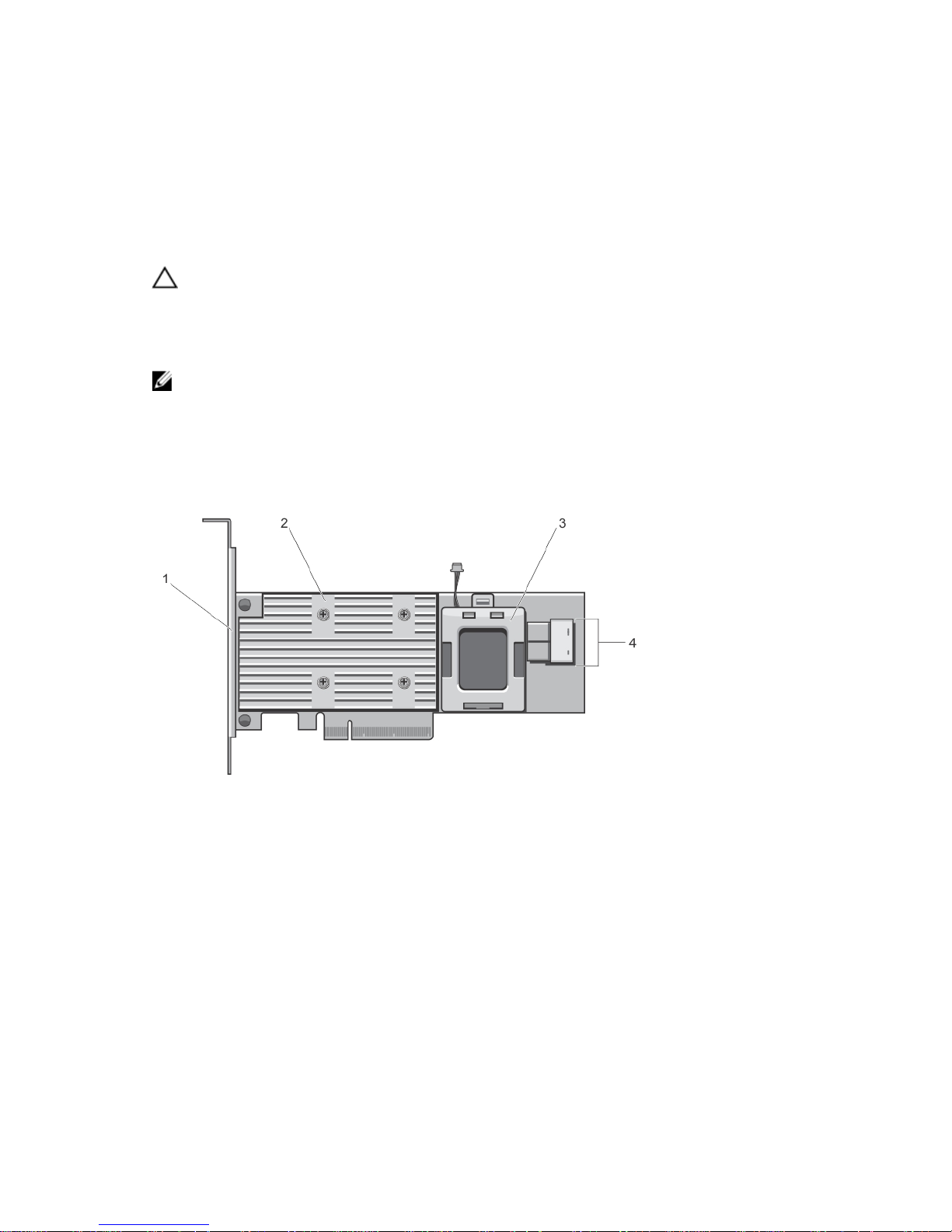
PERC H730P Card Features
Figure 1. Features Of PERC H730P Card
1. bracket 2. PERC H730P card
3. battery carrier 4. SAS cable connectors
27

Removing The PERC H730P Card
CAUTION: Many repairs may only be done by a certified service technician. You should only
perform troubleshooting and simple repairs as authorized in your product documentation, or as
directed by the online or telephone service and support team. Damage due to servicing that is
not authorized by Dell is not covered by your warranty. Read and follow the safety instructions
that came with the product.
1. Turn off the system, including any attached peripherals, and disconnect the system from the
electrical outlet and peripherals.
2. Open the system.
3. Remove the Network Daughter Card (NDC) riser.
4. Locate the PERC H730P card next to the power supply bay, under the clamp.
5. Press and open the clamp.
CAUTION: To prevent damage to the card, you must hold the card by its edges only.
6. Lift the card to remove it from the connector on the system board.
7. Disconnect the SAS cables connected to the card:
a. Press down and hold the metal tab on the SAS cable connector.
b. Pull the SAS cable out of the connector.
8. Return the clamp to the closed position.
9. Close the system.
28
10. Reconnect the system to its electrical outlet and turn the system on, including any attached
peripherals.
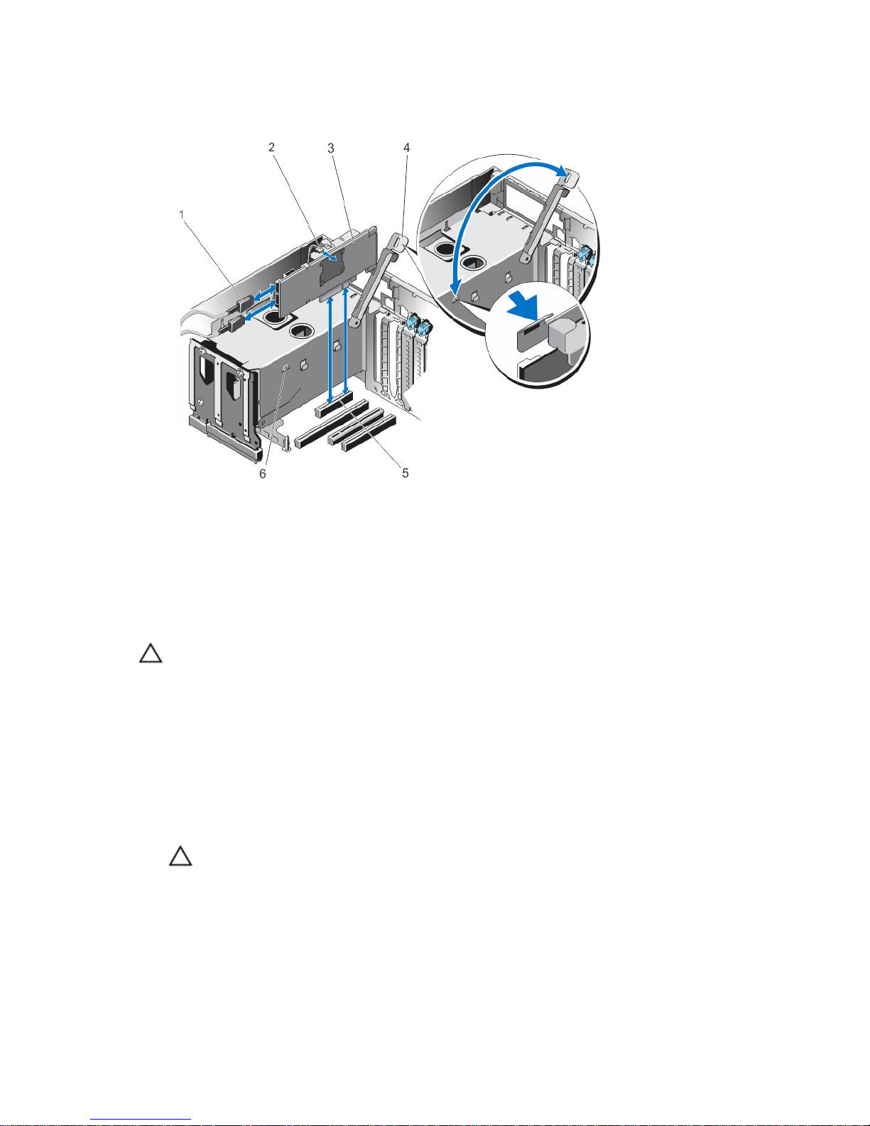
Figure 2. Removing and Installing the PERC H730P Card
1. SAS cable connector (2) 2. card battery
3. PERC H730P card 4. clamp
5. card connector on the system board 6. clamp slots on the power supply bay
Installing The PERC H730P Card
CAUTION: Many repairs may only be done by a certified service technician. You should only
perform troubleshooting and simple repairs as authorized in your product documentation, or as
directed by the online or telephone service and support team. Damage due to servicing that is
not authorized by Dell is not covered by your warranty. Read and follow the safety instructions
that came with the product.
1. Turn off the system, including any attached peripherals, and disconnect the system from the
electrical outlet.
2. Open the system.
3. Remove the NDC riser.
4. Lift the clamp attached to power supply bay and locate the PERC H730P card connector on the
system board.
CAUTION: To prevent damage to the card, you must hold the card by its edges only.
5. Align the card-edge connector with the connector on the system board.
6. Press the card-edge down until the card is fully seated.
29
7. Connect the SAS data cable connector to the card.
NOTE: Ensure that you connect the cable according to the connector labels on the cable. The
cable does not function properly if reversed.
8. Route the SAS data cable through the clip on the card and through the channel on the inner side of
the chassis.
9. Attach the connector labeled "SAS A" to connector SAS A on the backplane, and attach the
connector labeled "SAS B" to connector SAS B on the backplane.
10. Close the clamp.
11. Install the NDC riser.
12. Close the system.
13. Reconnect the system to its electrical outlet and turn the system on, including any attached
peripherals.
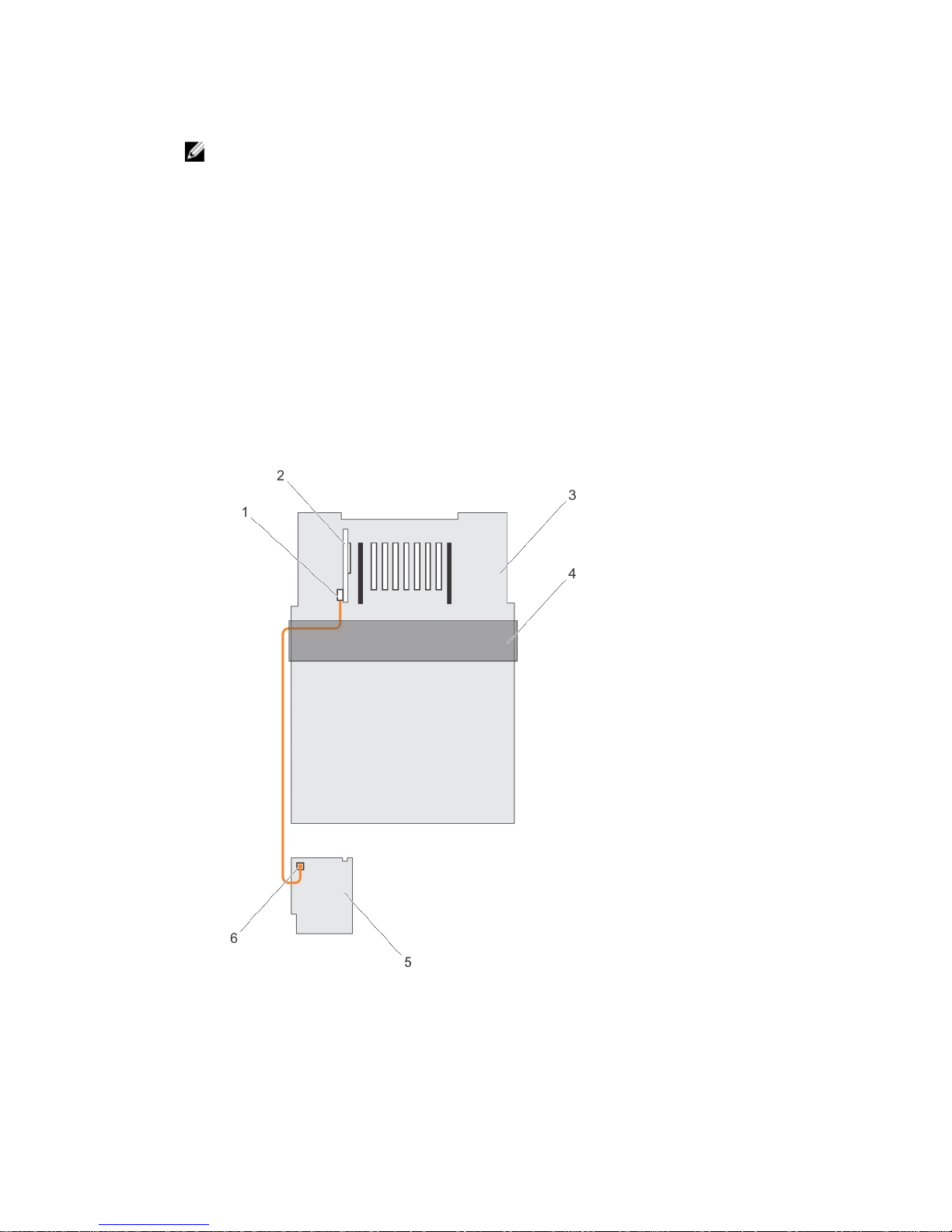
Cabling The PERC H730P Card
This section provides information about cabling the PERC H730P card on the the Dell PowerEdge R920
systems.
Figure 3. Cabling Diagram–2.5 Inch (x4) SAS/SATA Backplane with PERC H730P Card
1. SAS cable connector on the PERC H730P card 2. PERC H730P card
30
 Loading...