

Page 1

Dell PowerEdge C6320
Getting Started
With Your System
系统使用入门
Mengaktifkan Sistem Anda
はじめに
시스템 시작 안내서
Page 2
Scan to see how-to videos, documentation, and
troubleshooting information.
扫描以查看使用指导视频、说明文件和故障排除信息。
Pindai untuk melihat video cara melakukan, dokumentasi, dan
informasi pemecahan masalah.
スキャンしてハウツービデオ、マニュアル、トラブルシュ
ーティング情報を参照してください。
비디오, 문서 및 문제 해결 정보를 확인하려면 스캔하십시오.
Page 3

Dell PowerEdge
C6320
Getting Started
With Your System
Page 4
Notes, Cautions, and Warnings
NOTE: A NOTE indicates important information that helps you make better
use of your computer.
CAUTION: A CAUTION indicates potential damage to hardware or
loss of data if instructions are not followed.
WARNING: A WARNING indicates a potential for property damage,
personal injury, or death.
Page 5

______________
Copyright © 2015 Dell Inc. All rights reserved. This product is protected by U.S. and international
copyright and intellectual property laws. Dell™ and the Dell logo are trademarks of Dell Inc. in the
United States and/or other jurisdictions. All other marks and names mentioned herein may be
trademarks of their respective companies.
Regulatory Model: B08S Regulatory Type: B08S003
2015 - 03 P/N 3RKD9 Rev. A00
Page 6
CAUTION: Restricted Access Location
This server is intended for installation only in restricted access locations as defined in
Cl. 1.2.7.3 of IEC 60950-1: 2001 where both these conditions apply:
• Access can only be gained by service persons or by users who have been
instructed about the reasons for the restrictions applied to the location and about
any precautions that shall be taken.
• Access is through the use of a tool or lock and key, or other means of security,
and is controlled by the authority responsible for the location.
Installation and Configuration
WARNING: Before performing the following procedure, review and follow
the safety instructions that came with the system.
Installing the Tool-Less Rail Solution
WARNING: Whenever you need to lift the system, get others to assist
you. To avoid injury, do not attempt to lift the system by yourself.
WARNING: The system is not fixed to the rack or mounted on the
rails. To avoid personal injury or damage to the system, you must
adequately support the system during installation and removal.
WARNING: To avoid a potential electrical shock hazard, a third wire
safety grounding conductor is necessary for the rack installation.
The rack equipment must provide sufficient airflow to the system to
maintain proper cooling.
CAUTION: When installing rails in a square-hole rack it is important
to ensure that the square peg slides through the square holes.
6 | Getting Started With Your System
Page 7
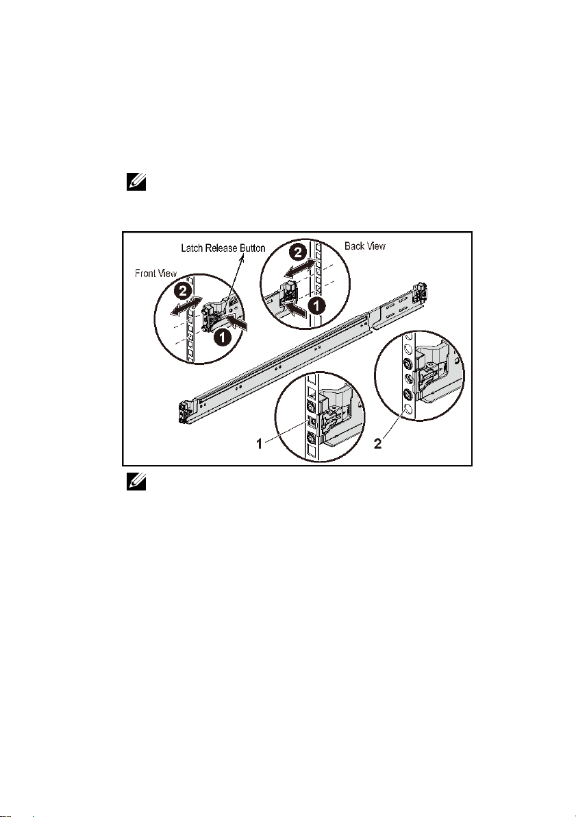
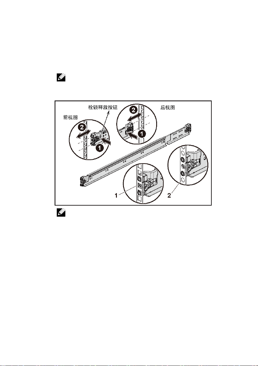
1 Push the latch release buttons on the midpoints of the end piece to open the
rail latches. See Figure 1.
2 Align the end pieces of the rails on the vertical rack flanges to seat the pegs
in the bottom hole of the first U and the top hole of the second U.
NOTE: The rails can be used in both square-hole (item 1 in the
following figure) and round-hole racks (item 2 in the following figure).
Figure 1. Pushing the Latch Release Buttons
NOTE: To remove the rails, push the latch release button on the
midpoints of the end piece and unseat each rail.
Getting Started With Your System | 7
Page 8
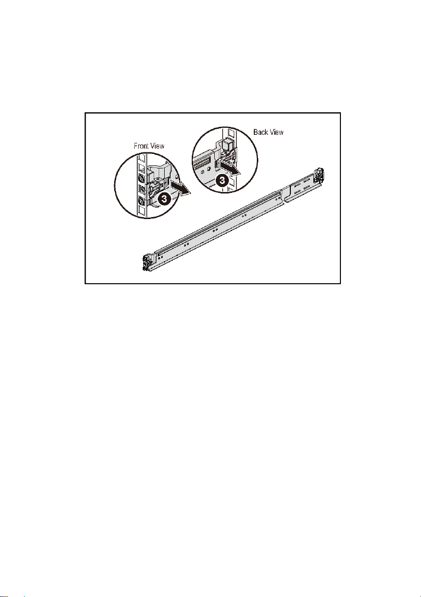
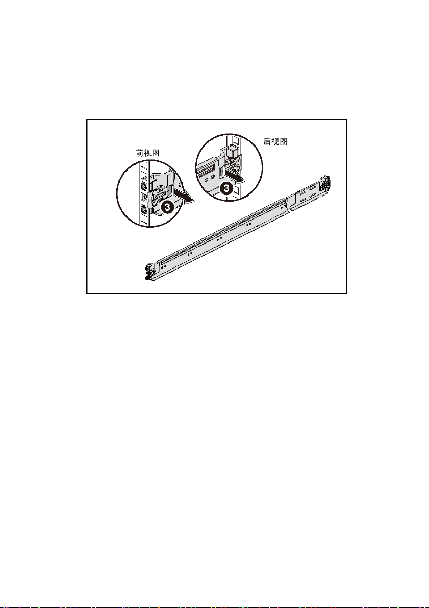
3 Engage the end of the rails and release the latch release button to have the
latches locked in place. See Figure 2.
Figure 2. Releasing the Latch Release Buttons
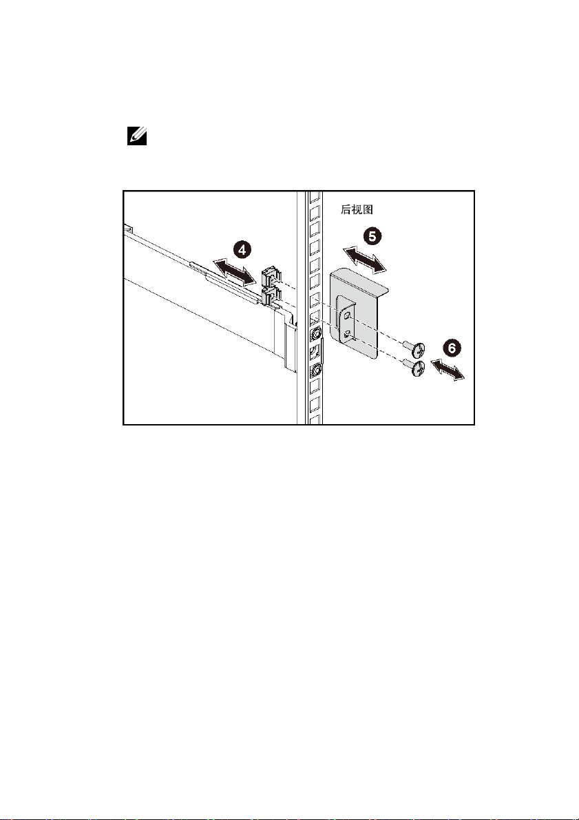
4 On each vertical rack flange on the back, put two screw bases into the two
square holes right above the rail. See Figure 3.
5 Install the chassis stabilizer shipping brackets (optional) on the back rack
flanges.
8 | Getting Started With Your System
Page 9
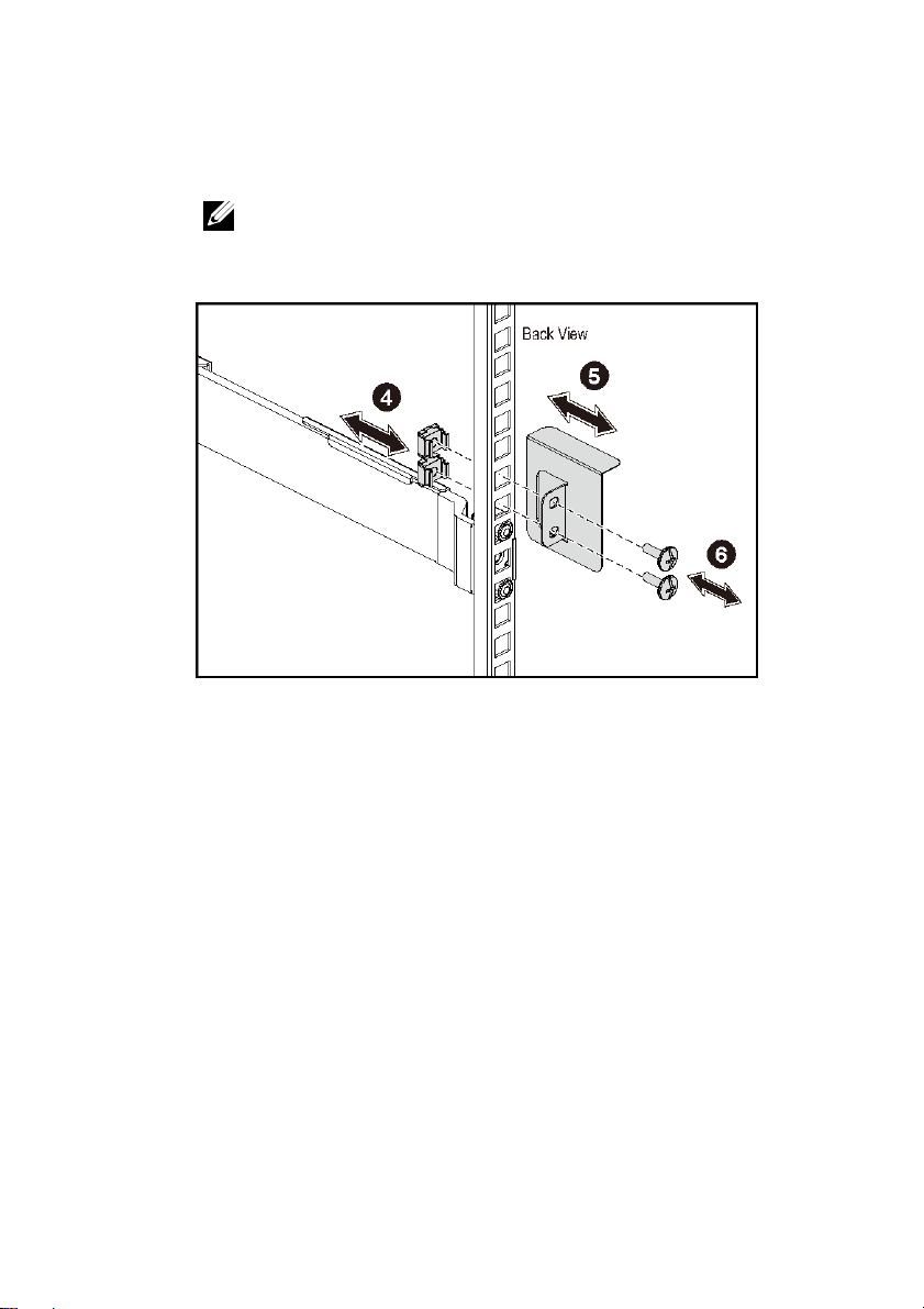
6 Install and tighten the screws.
NOTE: To transport systems already installed in the rack, ensure
that the two chassis stabilizer shipping brackets (optional) are in
place.
Figure 3. Installing the Chassis Stabilizer Shipping Brackets
Getting Started With Your System | 9
Page 10
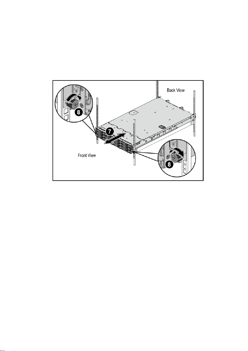
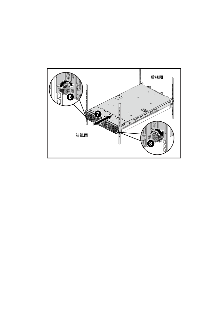
7 Slide the system into the rack. See Figure 4.
8 Tighten the thumbscrews to secure the ears of the system to the front of the
rack flanges.
Figure 4. Installing the Chassis onto the Rack.
10 | Getting Started With Your System
Page 11
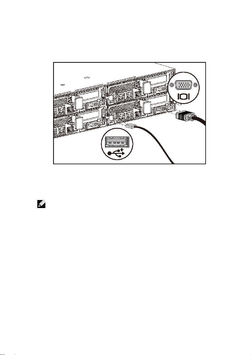
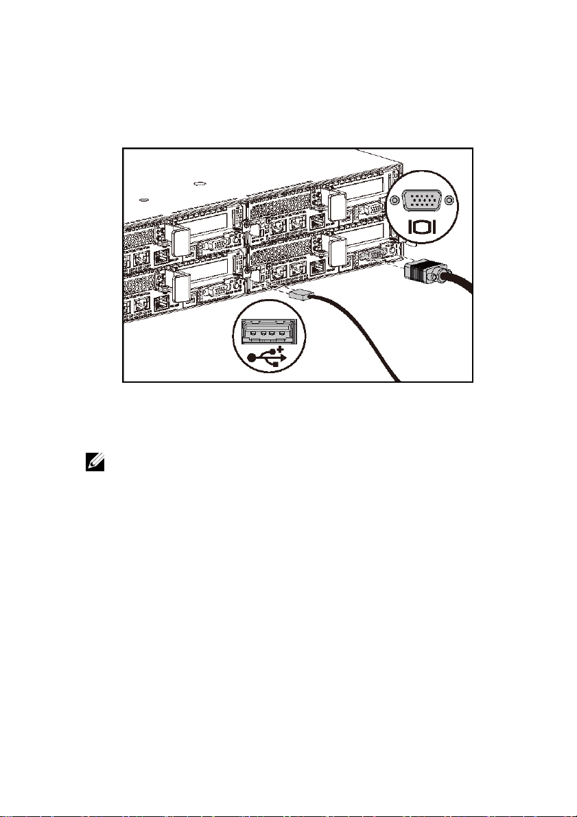
Optional—Connecting the Keyboard, Mouse, and Monitor
Figure 5. Optional—Connecting the Keyboard, Mouse and Monitor
Connect the keyboard, mouse, and monitor (optional).
The connectors on the back of your system have icons indicating which cable to plug
into each connector. Be sure to tighten the screws (if any) on the monitor’s cable
connector.
NOTE: Note that the system supports only one USB port and a micro USB
port. If you require more than one USB outlet at a time, use USB Hub or
Adapter Cable.
Getting Started With Your System | 11
Page 12
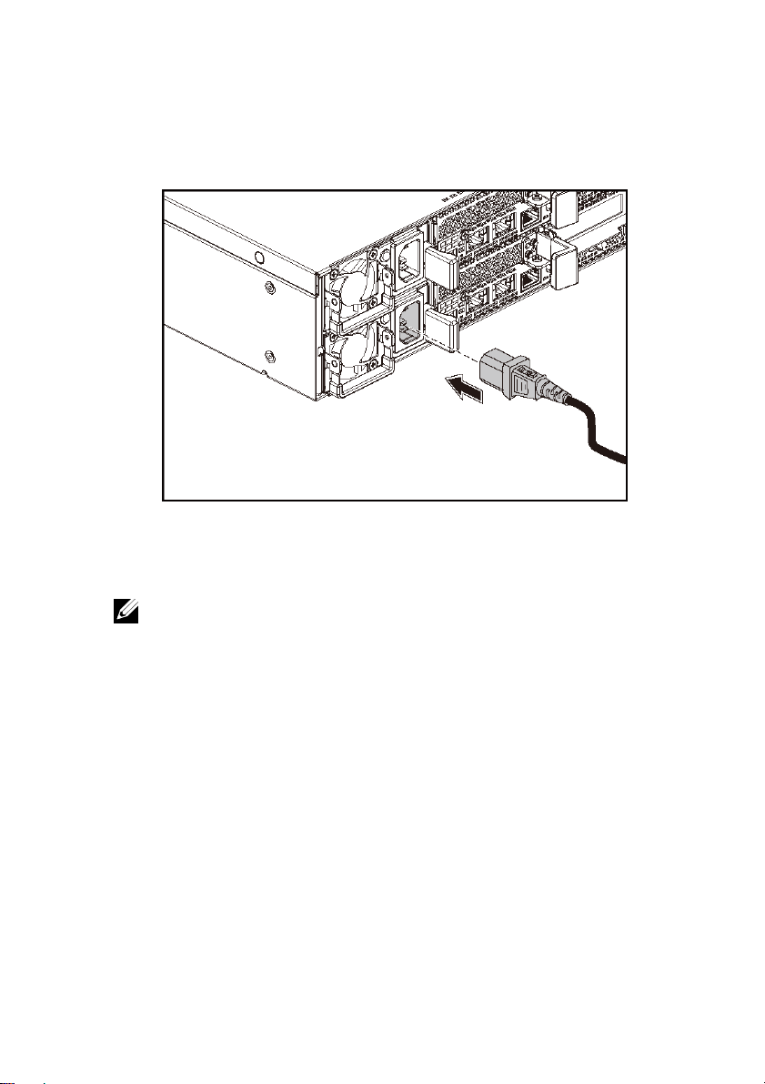
Connecting the Power Cable(s)
Figure 6. Connecting the Power Cable
Connect the system’s power cable(s) to the system and, if a monitor is used, connect the
monitor’s power cable to the monitor. Plug the other end of the power cables into a
grounded electrical outlet or a separate power source such as an uninterrupted power
supply or a power distribution unit.
NOTE: The system supports both AC and HVDC power inputs. Your
system can support up to two 1400 W power supply units (200-240 VAC
nominal input voltage) or up to two 1600 W power supply units
(200-240 VAC nominal input voltage). 1400 W power supply unit is
supported only for China.
12 | Getting Started With Your System
Page 13
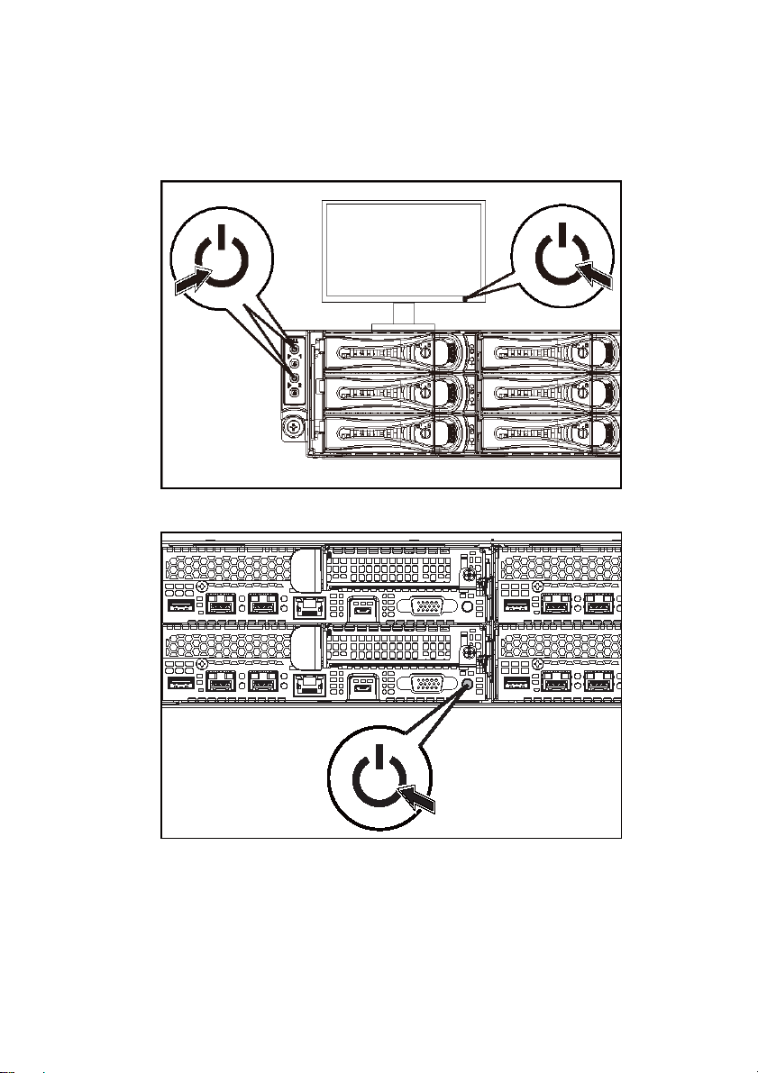
Turning on the System
Figure 7. Pressing the Power Button on the Front of the System
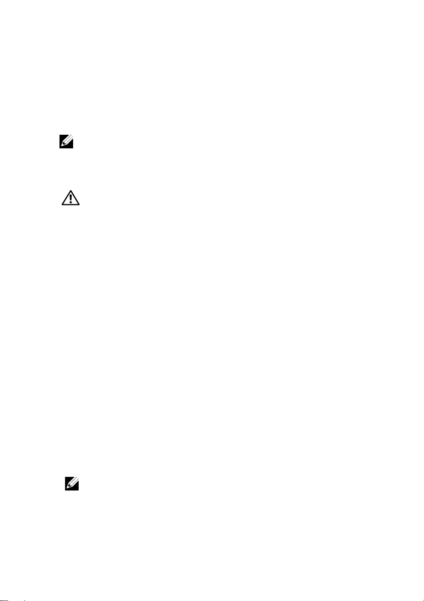
Figure 8. Pressing the Power Button on the Back of the System
Press the power button(s) either on the front or back of the system. The power indicators
should light green.
Getting Started With Your System | 13
Page 14
Complete the Operating System Setup
To install an operating system for the first time, see the installation and configuration
documentation for your operating system. Be sure the operating system is installed
before installing hardware or software not purchased with the system.
NOTE: See dell.com/ossupport for the latest information on supported operating
systems.
Other Information You May Need
The Hardware Owner’s Manual provides information about system features and
describes how to troubleshoot the system and install or replace system components. This
document is available at dell.com/support/home.
Dell systems management application documentation provides information about
installing and using the systems management software. This document is available
online at dell.com/support/home.
For an immediate access to your system information:
The support page that lists the system manuals is displayed.
For more information about your system:
WARNING: See the safety and regulatory information that shipped with
your system. Warranty information may be included within this document
or as a separate document.
1. Go to dell.com/support.
2. Enter your system service tag in the Enter your Service Tag field.
3. Click Submit.
1. Go to dell.com/support.
2. Select your country from the drop-down menu on the top left corner of
the page.
a. Select your product category.
b. Select your product segment.
c. Select your product.
The support page that lists the various support categories is displayed.
NOTE: Always check for updates on dell.com/support/home and read the
updates first because they often supersede information in other documents.
14 | Getting Started With Your System
Page 15

NOM Information (Mexico Only)
The following information is provided on the device described in this document in
compliance with the requirements of the official Mexican standards (NOM):
Importer Dell Inc. de México, S.A. de C.V.
Paseo de la Reforma 2620-11° Piso
Col. Lomas Atlas
11950 México, D.F.
Model number B08S
Supply voltage 200-240 V AC with 1400 W (for China
only) or 1600 W Power Supply Unit
Frequency 50/60 Hz
Current consumption 9 Amps with 1400 W Power Supply Unit
10 Amps with 1600 W Power Supply Unit
Technical Specifications
Processor Two Intel Xeon E5-2600 v3
Memory
Architecture 1600 MT/s, 1866 MT/s, or
2133 MT/s DDR4 Registered
DIMMs
Support for advanced ECC or
memory optimized operation
Memory module sockets Twelve 288-pin
Getting Started With Your System | 15
Page 16

Memory module capacities (RDIMMs) 8 GB and 16 GB dual-rank
Minimum RAM
Maximum RAM
16 GB
Up to 256 GB
Power
NOTE: The system does not support a mixed installation of 1400 W and
1600 W power supply units.
NOTE: The 1400 W and 1600 W power supply units are hot swappable,
and supports hot swap in any condition if the system has the power
throttling feature.
AC power supply (per power supply)
Wattage 1400 W (for China only)
Voltage 200-240 VAC, 50/60 Hz, maximum
input current: 9 Amps
Heat dissipation 6024.376 BTU/hr maximum
Maximum inrush current
Initial In-rush Current cannot exceed
55 Amps (peak). Secondary In-rush
Current cannot exceed 25 Amps
(peak).
Wattage 1600 W
Voltage
16 | Getting Started With Your System
200-240 VAC, 50/60 Hz, maximum
input current: 10 Amps
Page 17

Heat dissipation 6033.979 BTU/hr maximum
Maximum inrush current
Initial In-rush current and secondary
In-rush current cannot exceed
50 Amps (peak).
HVDC power supply (per power supply)
Wattage 1400 W (for China only)
Voltage 240 VDC, 50/60 Hz, maximum input
current: 9 Amps
Heat dissipation 5440.614 BTU/hr maximum
Maximum inrush current
Initial In-rush Current cannot exceed
55 Amps (peak). Secondary In-rush
Current cannot exceed 25 Amps
(peak).
Battery (per system board)
System battery CR 2032 3.0-V lithium ion coin cell
Physical
Height 8.68 cm (3.42 in)
Width 44.8 cm (17.6 in)
Depth 79.0 cm (31.1 in)
Weight (maximum configuration) 41 kg (90.38 lb)
(with 12*3.5” HDD)
39 kg (86.00 lb)
(with 24*2.5” HDD)
Getting Started With Your System | 17
Page 18

Weight (empty) 15.7 kg (34.61 lb)
(with 2.5” HDD bay)
15.1 kg (33.29 lb)
(with 3.5” HDD bay)
Environmental
NOTE: For additional information about environmental measurements for specific
system configurations, see www.dell.com/environmental_datasheets.
Temperature
Operating 10° to 35°C (50° to 95°F) with
a maximum temperature gradation of
10°C per hour
NOTE: For altitudes above 2950 feet,
the maximum operating temperature
is derated 1°F/550 ft.
CAUTION: The maximum number of
memory modules and hard drives
supported on 1U node configuration,
with 135W and 145W processors,
depends on the power supply
installed.
Storage –40° to 65°C (–40° to 149°F) with
a maximum temperature gradation of
20°C per hour
Relative humidity
Operating 20% to 80% (noncondensing) with
a maximum humidity gradation of
10% per hour
Storage 5% to 95% (noncondensing)
Maximum vibration
Operating 0.26 Grms at 5–350 Hz
Storage 1.88 Grms at 10–500 Hz for 15 min
Maximum shock
18 | Getting Started With Your System
Page 19

Operating One shock pulse in the positive
z axis (one pulse on each side of the
system) of 31 G for 2.6 ms in the
operational orientation
Storage Six consecutively executed shock
pulses in the positive and negative
x, y, and z axes (one pulse on each
side of the system) of 71 G for up to
2 ms;
Six consecutively executed shock
pulses in the positive and negative
x, y, and z axes (one pulse on each
side of the system) of 27 G faired
square wave pulse with velocity
change at 235 inches/second
(597 centimeters/second)
Altitude
Operating -15.2 to 3,048 m
(-50 to 10,000 ft.)
Storage -15.2 to 10,668 m
(-50 to 35,000 ft.)
Airborne Contaminant Level
Class G1 as defined by
ISA-S71.04-1985
Getting Started With Your System | 19
Page 20

Dell PowerEdge
C6320
系统使用入门
Page 21
注、小心和警告
注:“注”表示可以帮助您更好地使用计算机的重要信息。
小心:“小心”表示如果不遵循说明,就有可能损坏硬件或导致数据丢失。
警告:“警告”表示可能会导致财产损失、人身伤害甚至死亡。
Page 22

______________
© 2015 Dell, Inc.。版权所有,翻印必究。本产品受到美国和国际版权以及知识产权法律保护。Dell™ 和 Dell
徽标是 Dell Inc. 在美国和/或其他司法管辖区的商标。本文中提及的所有其他标记和名称可能是其各自公司的
商标。
法规型号:B08S 法规类型:B08S003
2015 - 03 P/N 3RKD9 Rev. A00
Page 23
小心:受限访问位置
此服务器仅用于安装在由 IEC 60950-1: 2001 的 Cl. 1.2.7.3 定义的满足下列两个条
件的受限访问位置中:
• 仅维修人员或对该位置施加限制的理由以及应当采取的防备措施已完全领
会的用户,方可对此服务器进行访问。
• 访问是通过使用工具或锁和钥匙,或其他安全手段来实现,并且由负责该
位置的管理机构来控制。
安装和配置
警告:执行下列步骤之前,请先阅读并遵循系统随附的安全说明。
安装免工具拆装滑轨解决方案
警告:需要提起系统时,请让其他人进行协助。为避免受伤,请勿尝试
独自提起系统。
警告:系统并未固定到机架上,也并没有安装在滑轨上。为避免人身伤害
或系统损坏,在安装和拆卸时,必须给系统提供足够的支撑。
警告:为避免可能的电击伤害,安装机架时需要第三根导线的安全接地
线。机架设备必须为系统提供足够的通风以维持适当的冷却效果。
小心:在方孔机架中安装导轨时,务必确保方形插销穿过方孔。
24 | 系统使用入门
Page 24
1 请按压尾段正中央的闩锁释放按钮以打开滑轨闩锁。请参阅图 1。
2 在机架垂直凸缘上对齐滑轨的尾段,将插销分别插入第一个 U 型螺栓
的底孔中和第二个 U 型螺栓的顶孔中。
注:滑轨在方孔机架(下图中的项目 1)和圆孔机架(下图中的项目 2)
中均可使用。
图 1。按压闩锁释放按钮
注:要卸下滑轨,请按压尾段正中央的闩锁释放按钮并取下每根滑轨。
系统使用入门 | 25
Page 25
3 接入各个滑轨的尾端并松开闩锁释放按钮以使闩锁锁定到位。
请参阅图 2。
图 2。松开闩锁释放按钮
4 在背面的每个垂直机架凸缘上,将两颗螺钉座放入机架正上方的两个
方孔内。请参阅图 3。
5 将运输时稳固机箱的支架(可选件)安装在机架背面的凸缘上。
26 | 系统使用入门
Page 26
6 装回并拧紧螺钉。
注:要运输已经安装在机架上的系统,请确保两个运输时稳固机箱的
支架到位(可选)。
图 3。安装运输时稳固机箱的支架
系统使用入门 | 27
Page 27
7 将系统滑入到机架中。请参阅图 4。
8 拧紧指旋螺钉,将系统的耳柄固定到机架凸缘正面。
图 4。将机箱安装到机架上。
28 | 系统使用入门
Page 28
可选 — 连接键盘、鼠标和显示器
图 5。可选 — 连接键盘、鼠标和显示器
连接键盘、鼠标和显示器(可选)。
系统背面的连接器附有图标,这些图标指示了要插入每个连接器的电缆。确保
拧紧显示器电缆连接器上的螺钉(如果有)。
注:请注意,系统仅支持一个 USB 端口和一个微型 USB 端口。如果您同时
需要多个 USB 插座,使用 USB 集线器或适配器电缆。
系统使用入门 | 29
Page 29

连接电源电缆
图 6。连接电源电缆
将系统电源电缆连接至系统,如果使用显示器,将显示器电源电缆连接至显示器。
将电源电缆的另一端插入接地的电源插座或单独的电源,例如不间断电源设备或
配电装置。
注:此系统支持交流和 HVDC 电源输入。您的系统支持多达两个 1400 W 电源
设备装置(200-240 VAC 标称输入电压)或最多两个 1600 W 电源设备装置
(200-240 VAC 标称输入电压)。1400 W 电源设备装置仅适用于中国。
30 | 系统使用入门
Page 30

开启系统
图 7。按下系统正面的电源按钮
图 8。按下系统背面的电源按钮
按下系统正面或背面的电源按钮。电源指示灯应呈绿色亮起。
系统使用入门 | 31
Page 31

完成操作系统设置
第一次安装操作系统时,请参阅操作系统的安装和配置说明文件。请确保先安装
操作系统,然后再安装并非随系统购买的硬件或软件。
注:有关支持的操作系统的最新信息,请参阅 dell.com/ossupport。
您可能需要的其他信息
警告:请参阅系统附带的安全与管制信息。保修信息可能包括在该说明文件中,
也可能作为单独的说明文件提供。
《硬件用户手册》提供了有关系统功能的信息,并说明了如何排除系统故障以及
安装或更换系统组件。此说明文件可从 dell.com/support/home 获得。
Dell 系统管理应用程序说明文件提供了有关如何安装和使用系统管理软件的信息。
此说明文件可从 dell.com/support/home 在线获取。
对于即时访问系统信息,请执行以下操作:
1. 转至 dell.com/support。
2. 在“输入您的服务标签”字段中输入您的系统服务标签。
3. 单击 Submit(提交)。
此时将显示列出系统手册的支持页面。
有关系统的更多信息,请执行以下操作:
1. 转至 dell.com/support。
2. 从页面左上角的下拉菜单中选择您所在的国家(地区)。
a. 选择您的产品类别。
b. 选择您的产品分类。
c. 选择您的产品。
此时将显示其中列出各种支持类别的支持页面。
注:请经常访问 dell.com/support/home 以获得更新,并首先阅读这些更新,
因为这些更新通常会取代其它说明文件中的信息。
32 | 系统使用入门
Page 32

NOM 信息(仅限于墨西哥)
根据墨西哥官方标准 (NOM),本说明文件中述及的的设备上必须提供以下信息:
进口商
型号
电源电压 200-240 V 交流,带 1400 W (仅限
频率
电流消耗 9 安培,带 1400 W 电源设备装置
Dell Inc. de México, S.A. de C.V.
Paseo de la Reforma 2620-11° Piso
Col. Lomas Atlas
11950 México, D.F.
B08S
中国)或 1600 W 电源设备装置
50/60 Hz
10 安培,带 1600 W 电源设备装置
技术规格
处理器 两个 Intel Xeon E5-2600 v3
内存
体系结构 1600 MT/s、1866 MT/s 或
2133 MT/s DDR4 带寄存器
的 DIMM
支持高级 ECC 或内存优化
操作
系统使用入门 | 33
Page 33

内存模块插槽 十二个 288 针
/
内存模块容量 (RDIMM) 8 GB 和 16 GB 双列
最小 RAM
最大 RAM
16 GB
高达 256 GB
电源
注:系统不支持混合安装 1400 W 和 1600 W 电源设备。
注:1400 W 和 1600 W 电源设备可以热插拔,如果系统具有电源
节流功能,则支持任何情况下的热交换。
交流电源设备(每个电源设备)
功率 1400 W(仅限中国)
电压 200-240 V 交流,50/60 Hz,最大
输入电流:9 安培
散热 6024.376 BTU
最大涌入电流
初始涌入电流不能超过 55 安培
(峰值)。二次涌入电流不能超
过 25 安培(峰值)。
小时最大
功率 1600 W
电压
34 | 系统使用入门
200-240 V 交流,50/60 Hz ,
最大输入电流:10 安培
Page 34

/
散热 6033.979 BTU
最大涌入电流
初始涌入电流和次涌入电流不能
超过 50 安培(峰值)。
小时最大
HVDC 电源设备(每个电源设备)
功率 1400 W(仅限中国)
电压 240 V 直流,50/60 Hz,最大输入
电流:9 安培
散热 5440.614 BTU/小时最大
最大涌入电流
初始涌入电流不能超过 55 安培
(峰值)。二次涌入电流不能
超过 25 安培(峰值)。
电池(每个系统板)
系统电池 CR 2032 3.0 V 币形锂电池
物理规格
高度 8.68 厘米(3.42 英寸)
宽度 44.8 厘米(17.6 英寸)
厚度 79.0 厘米(31.1 英寸)
重量(最大配置) 41 千克(90.38 磅)
(配备 12 个 3.5 英寸 HDD)
39 千克(86.00 磅)
(配备 24 个 2.5 英寸 HDD)
系统使用入门 | 35
Page 35

重量(空置) 15.7 千克(34.61 磅)
(配备 2.5 英寸 HDD 托架)
15.1 千克(33.29 磅)
(配备 3.5 英寸 HDD 托架)
环境参数
注:有关特定系统配置的环境测量值的更多信息,请访问
www.dell.com/environmental_datasheets
温度
。
运行时 10 °C 至 35 °C(50 °F 至 95 °F),
最大温度变化梯度为每小时 10 °C
注:海拔高度在 2950 英尺以上时,
最高操作温度降幅为 1 °F/550 ft。
警告:
1U
节点配置上支持的最大内存模
块和硬盘数量(配有
理器)取决于所安装的电源设备。
135 瓦和 145
瓦处
存储时 -40° 至 65°C(-40° 至 149°F),最
大温度变化梯度为每小时 20°C
相对湿度
运行时 20% 至 80% (非冷凝),
最大湿度变化梯度为每小时 10%
存储时 5% 至 95%(非冷凝)
最大振动
运行时 5 – 350 Hz 时为 0.26 Grms
存储时 在 10 – 500 Hz、1.88 Grms 时,
可持续 15 分钟
36 | 系统使用入门
Page 36

最大撞击
运行时
在操作方向,z 轴正方向上可承受
一个
31 G
的撞击脉冲(系统每一面
承受一个脉冲),可持续
2.6 毫秒
存储时 x、y 和 z 轴正负方向上可承受连续
六个 71 G 的撞击脉冲(系统每一
面承受一个脉冲),最长可持续
2 毫秒;
x、y 和 z 轴正负方向上可承受连续
六个 27 G 正弦波脉冲的撞击脉冲
(系统每一面承受一个脉冲),
速度变化为 235 英寸/ 秒
(597 厘米/秒)
海拔高度
运行时 -15.2 至 3,048 米
(-50 至 10,000 英尺)
存储时 -15.2 至 10,668 米
(-50 至 35,000 英尺)
气载污染物级别
分类 G1(依据 ISA-S71.04-1985 定义的
标准)
系统使用入门 | 37
Page 37

Page 38

Page 39

Dell PowerEdge
C6320
Mengaktifkan
Sistem Anda
Page 40

Catatan, Perhatian, dan Peringatan
CATATAN: CATATAN menunjukkan informasi penting yang akan
membantu Anda mengoptimalkan penggunaan komputer.
PERHATIAN: Sebuah PERHATIAN mengindikasikan potensi
kerusakan terhadap perangkat keras atau kehilangan data jika
petunjuk tidak diikuti.
PERINGATAN: Sebuah PERINGATAN mengindikasikan potensi
kerusakan properti, cedera diri, atau kematian.
Page 41

______________
Copyright © 2015 Dell Inc. Hak cipta dilindungi undang-undang. Produk ini dilindungi oleh undangundang hak cipta dan hak atas kekayaan intelektual di AS. Dell™ dan logo Dell adalah merek dagang
dari Dell Inc. di Amerika Serikat dan/atau yurisdiksi lainnya. Semua merek dan mana lain yang
disebutkan di sini bisa jadi merupakan merek dagang dari perusahaannya yang bersangkutan.
Model Regulatori: B08S Jenis Regulatori: B08S003
2015 - 03 No. Komp. 3RKD9 Rev. A00
Page 42

PERHATIAN: Lokasi Akses Terbatas
Server ini ditujukan untuk instalasi hanya di lokasi akses terbatas sebagaimana
didefinisikan dalam Cl. 1.2.7.3 dalam IEC 60950-1: 2001 di mana berlaku kedua
kondisi berikut:
• Akses hanya dapat dilakukan oleh petugas servis atau oleh pengguna yang telah
mendapatkan penjelasan tentang batasan yang diterapkan pada lokasi dan tentang
tindakan pencegahan yang harus dilakukan.
• Akses dapat dilakukan dengan menggunakan alat atau kunci dan anak kunci, atau
sarana pengaman lainnya, dan dikontrol oleh pihak berwenang yang bertanggung
jawab atas lokasi tersebut.
Instalasi dan Konfigurasi
PERINGATAN:Sebelum melakukan prosedur berikut, bacalah dan ikuti
petunjuk keselamatan yang disertakan dengan sistem.
Menginstal Solusi Rel Tanpa Alat
PERINGATAN: Bilamana Anda hendak mengangkat sistem, mintalah
bantuan orang lain. Untuk mencegah cedera, jangan mencoba
mengangkat sistem sendirian.
PERINGATAN: Sistem belum terpasang pada rak atau digantung
pada relnya. Untuk mencegah cedera atau kerusakan pada sistem,
Anda harus menyangga sistem dengan baik selama instalasi dan
melepaskan sistem.
PERINGATAN: Untuk mencegah potensi bahaya tersengat listrik,
diperlukan konduktor dengan kabel ketiga yang ditanahkan sebagai
pengaman untuk menginstal rak. Perlengkapan rak harus
menyediakan aliran udara yang memadai untuk menjaga
pendinginan yang dibutuhkan.
PERHATIAN: Ketika menginstal rel pada rak dengan lubang persegi,
penting untuk memastikan bahwa pasak persegi menembus lubang
persegi.
42 | Mengaktifkan Sistem Anda
Page 43

1 Tekan tombol pembuka kait di titik tengah bagian ujung untuk membuka
pengait rel. Lihat Gambar 1.
2 Sesuaikan bagian ujung rel pada flensa rak vertikal untuk mendudukkan
pasak pada lubang bawah U pertama dan lubang atas U kedua.
CATATAN: Rel dapat digunakan pada rak lubang persegi (butir 1 pada
gambar berikut) dan rak lubang bulat (butir 2 pada gambar berikut).
Gambar 1. Menekan Tombol Pembuka Kait
CATATAN: Untuk melepaskan rel, tekan tombol pembuka kait di
titik tengah bagian ujung dan lepaskan setiap rel.
Mengaktifkan Sistem Anda | 43
Page 44

3 Tarik bagian ujung rel dan lepaskan tombol pembuka kait agar kait terkunci
pada tempatnya. Lihat Gambar 2.
Gambar 2. Gambar Melepaskan Tombol Pembuka Kait
4 Pada setiap flensa rak vertikal di bagian belakang, letakkan dua dasar
sekrup ke dalam dua lubang persegi di atas rel. Lihat Gambar 3.
5 Pasang braket pengiriman penstabil chasis (opsional) di bagian belakang
flensa rak.
44 | Mengaktifkan Sistem Anda
Page 45

6 Pasang dan kencangkan sekrup.
CATATAN: Untuk memindahkan sistem yang sudah terpasang pada
rak, pastikan bahwa kedua braket pengiriman penstabil chasis
(opsional) telah terpasang.
Gambar 3. Menginstal Braket Pengiriman Penstabil Chasis
Mengaktifkan Sistem Anda | 45
Page 46

7 Geser sistem ke dalam rak. Lihat Gambar 4.
8 Kencangkan sekrup pengatur untuk mengencangkan telinga sistem ke
bagian depan flensa rak.
Gambar 4. Menginstal Chasis ke Rak.
46 | Mengaktifkan Sistem Anda
Page 47

Opsional—Menghubungkan Keyboard, Mouse, dan Monitor
Gambar 5. Opsional—Menghubungkan Keyboard, Mouse,
dan Monitor
Hubungkan keyboard, mouse, dan monitor (opsional).
Konektor di bagian belakang sistem Anda ditandai dengan ikon yang menunjukkan
kabel mana yang harus ditancapkan ke masing-masing konektor. Pastikan untuk
mengencangkan sekrup (jika ada) pada konektor kabel monitor.
CATATAN: Catat bahwa sistem tersebut hanya mendukung satu port USB
dan sebuah port micro USB. Jika Anda memerlukan lebih dari satu outlet
USB dalam satu waktu, gunakan Hub USB atau Kabel Adaptor.
Mengaktifkan Sistem Anda | 47
Page 48

Menghubungkan Kabel Daya
Gambar 6. Menghubungkan Kabel Daya
Hubungkan kabel daya sistem ke sistem dan, jika monitor digunakan, hubungkan kabel
daya monitor ke monitor. Tancapkan ujung kabel daya yang lain ke stopkontak listrik
yang ditanahkan atau sumber daya terpisah seperti catu daya tak terputus atau unit
distribusi daya.
CATATAN: Sistem mendukung input daya AC dan HVDC. Sistem Anda
mendukung hingga dua unit catu daya 1400 W (tegangan input nominal
200-240 VAC) atau hingga dua unit catu daya 1600 W (tegangan input
nominal 200-240). Unit catu daya 1400 W didukung hanya untuk negara
Tiongkok.
48 | Mengaktifkan Sistem Anda
Page 49

Mengaktifkan Sistem
Gambar 7. Menekan Tombol Daya di Bagian Depan Sistem
Gambar 8. Menekan Tombol Daya di Bagian Belakang Sistem
Tekan tombol daya pada bagian depan atau belakang sistem. Indikator daya seharusnya
menyala hijau.
Mengaktifkan Sistem Anda | 49
Page 50

Menyelesaikan Pengaturan Sistem Operasi
Untuk menginstal sistem operasi untuk pertama kalinya, lihat dokumentasi instalasi dan
konfigurasi untuk sistem operasi Anda. Pastikan bahwa sistem operasi telah terinstal sebelum
Anda menginstal perangkat keras atau perangkat lunak yang tidak dibeli bersama sistem.
CATATAN: Lihat dell.com/ossupport untuk mendapatkan informasi terbaru
tentang sistem operasi yang didukung.
Informasi Lain yang Mungkin Anda Perlukan
Manual Perangkat Keras untuk Pemilik menyediakan informasi mengenai fitur sistem
dan menjelaskan bagaimana cara penelusuran kesalahan sistem dan penginstalan atau
penggantian komponen. Dokumen ini tersedia di dell.com/support/home.
Dokumentasi aplikasi manajemen sistem Dell menyediakan informasi mengenai
penginstalan dan penggunaan perangkat lunak manajemen sistem. Dokumen ini tersedia
secara online di dell.com/support/home.
Untuk akses segera ke informasi sistem Anda:
Halaman dukungan yang mencantumkan manual sistem akan ditampilkan.
Untuk informasi selengkapnya tentang sistem Anda:
PERINGATAN: Lihat informasi keselamatan dan regulasi yang dikirimkan
bersama sistem Anda. Informasi garansi mungkin disertakan dalam
dokumen ini atau sebagai dokumen yang terpisah.
1. Kunjungi dell.com/support.
2. Masukkan tag servis sistem Anda ke dalam bidang Service Tag (Tag Servis).
3. Klik Submit (Ajukan).
1. Kunjungi dell.com/support.
2. Pilih negara Anda dari menu tarik-turun di sudut kiri atas halaman tersebut.
a. Pilih kategori produk Anda.
b. Pilih segmen produk Anda.
c. Pilih produk Anda.
Halaman dukungan yang mencantumkan berbagai kategori dukungan akan
ditampilkan.
CATATAN: Selalu periksa pembaruan pada situs dell.com/support/home dan
bacalah pembaruan tersebut terlebih dahulu karena seringkali menggantikan
informasi dalam dokumen lain.
50 | Mengaktifkan Sistem Anda
Page 51

Informasi NOM (Hanya Meksiko)
Informasi berikut tersedia pada perangkat yang diuraikan dalam dokumen ini untuk
memenuhi persyaratan standar resmi Meksiko (NOM):
Importir:
Dell Inc. de México, S.A. de C.V.
Paseo de la Reforma 2620-11° Piso
Col. Lomas Atlas
11950 México, D.F.
Nomor model:
Tegangan catu:
Frekuensi
Konsumsi arus
B08S
200-240 V AC dengan Unit Catu Daya
1400 W (untuk Tiongkok saja) atau 1600 W
50/60 Hz
9 Amp dengan Unit Catu Daya 1400 W
10 Amp dengan Unit Catu Daya 1600 W
Spesifikasi Teknis
Prosesor Dua buah Intel Xeon
E5-2600 v3
Memori
Arsitektur
1600 MT/dtk, 1866 MT/dtk,
atau 2133 MT/dtk DDR4
Registered DIMM
Dukungan untuk
pengoperasian ECC tingkat
lanjut atau memori
teroptimalkan
Mengaktifkan Sistem Anda | 51
Page 52

Soket modul memori
Dua belas 288-pin
Kapasitas modul memori (RDIMM) 8 GB dan 16 GB ranking
ganda
RAM minimum
RAM maksimum
16 GB
Hingga 256 GB
Daya
CATATAN: Sistem ini tidak mendukung instalasi campuran antara unit
catu daya 1400 W dan 1600 W.
CATATAN: Unit catu daya 1400 W dan 1600 W merupakan unit yang
dapat diganti saat perangkat dihidupkan dalam kondisi apa pun jika
sistem tersebut memiliki fitur throttling daya.
Catu daya AC (per catu daya)
Watt 1400 W (untuk Tiongkok saja)
Tegangan 200-240 VAC, 50/60 Hz, arus input
maksimum: 9 Amp
Pelepasan panas 6024,376 BTU/jam maksimum
Lonjakan arus maksimum
Lonjakan Arus Awal tidak boleh
melebihi 55 Amp (puncak).
Lonjakan Arus Sekunder tidak boleh
melebihi 25 Amp (puncak).
Watt 1600 W
Tegangan 200-240 VAC, 50/60 Hz, arus input
maksimum: 10 Amp
52 | Mengaktifkan Sistem Anda
Page 53

Pelepasan panas 6033,979 BTU/jam maksimum
Lonjakan arus maksimum
Lonjakan arus awal dan Lonjakan
arus sekunder tidak boleh melebihi
50 Amp (puncak).
Catu daya HVDC (per catu daya)
Watt
Tegangan
Pelepasan panas
Lonjakan arus maksimum
Baterai (per board sistem)
Baterai sistem
Fisik
Tinggi
Panjang
Lebar
Berat (konfigurasi maksimum)
1400 W (untuk Tiongkok saja)
240 VDC, 50/60 Hz, arus input
maksimum: 9 Amp
5440,614 BTU/jam maksimum
Lonjakan Arus Awal tidak boleh
melebihi 55 Amp (puncak).
Lonjakan Arus Sekunder tidak boleh
melebihi 25 Amp (puncak).
Sel berbentuk koin ion lithium
CR 2032 3,0-V
8,68 cm (3,42 inci)
44,8 cm (17,6 inci)
79,0 cm (31,1 inci)
41 kg (90,38 lb)
(dengan HDD 12*3,5”)
39 kg (86,00 lb)
(dengan HDD 24*2,5”)
Mengaktifkan Sistem Anda | 53
Page 54

Berat (kosong)
15,7 kg (34,61 lb)
(dengan bay HDD 2,5”)
15,1 kg (33,29 lb)
(dengan bay HDD 3,5”)
Lingkungan
CATATAN: Untuk informasi lebih lanjut mengenai pengukuran lingkungan untuk
konfigurasi sistem spesifik, lihat www.dell.com/environmental_datasheets
.
Suhu
Pengoperasian 10° hingga 35°C (50° hingga 95°F)
dengan gradasi suhu maksimum
10°C per jam
CATATAN: Pada ketinggian di atas
899,16 m (2.950 kaki), suhu
pengoperasian maksimum berkurang
1°F/167,64 m (550 kaki).
PERHATIAN: Jumlah maksimum
modul memori dan hard disk yang
didukung pada konfigurasi nodus 1U,
dengan prosesor 135W dan 145W,
bergantung pada catu daya yang
dipasang.
Penyimpanan -40° hingga 65°C (-40° hingga 149°F)
dengan gradasi suhu maksimum 20°C
per jam
Kelembapan relatif
Pengoperasian 20% sampai 80% (tanpa kondensasi)
dengan gradasi kelembapan
maksimum sebesar 10% per jam
Penyimpanan 5% hingga 95% (tanpa kondensasi)
Getaran maksimum
Pengoperasian 0,26 Grms pada 5-350 Hz
Penyimpanan 1,88 Grms pada 10-500 Hz selama
15 menit
54 | Mengaktifkan Sistem Anda
Page 55

Guncangan maksimum
Pengoperasian Satu pulsa guncangan pada sumbu
z positif (satu pulsa pada setiap sisi
sistem) sebesar 31 G selama 2,6 mdet
di dalam orientasi operasional
Penyimpanan Enam pulsa guncangan berturut-turut
pada sumbu x, y, dan z positif dan
negatif (satu pulsa pada setiap sisi
sistem) sebesar 71 G selama hingga
2 mdtk;
Enam pulsa guncangan berturut-turut
pada sumbu x, y, dan z positif dan
negatif (satu pulsa pada setiap sisi
sistem) sebesar 27 G pulsa
gelombang persegi dengan
perubahan kecepatan sebesar
235 inci/detik (597 sentimeter/detik)
Ketinggian
Pengoperasian -15,2 hingga 3048 m
(-50 hingga 10.000 kaki)
Penyimpanan -15,2 hingga 10.668 m
(-50 hingga 35.000 kaki)
Tingkat Pencemaran Udara
Kelas G1 sebagaimana didefinisikan oleh
ISA-S71.04-1985
Mengaktifkan Sistem Anda | 55
Page 56

Page 57

Dell PowerEdge
C6320
はじめに
Page 58

メモ、注意、警告
メモ:コンピュータを使いやすくするための重要な情報を説明しています。
注意:手順に従わないと、ハードウェアの損傷やデータの損失につながる
可能性があることを示しています。
警告:物的損害、けが、または死亡の原因となる可能性があることを示し
ています。
Page 59

______________
著作権 © 2015 Dell Inc. 無断転載を禁じます。本製品は、米国および国際著作権法、ならびに米国および国
際知的財産法で保護されています。Dell™、およびデルのロゴは、米国および / またはその他管轄区域におけ
る Dell Inc. の商標です。本書で使用されているその他すべての商標および名称は、各社の商標である場合が
あります。
認可モデル:B08S 認可タイプ: B08S003
2015 - 03 P/N 3RKD9 Rev.A00
Page 60

注意:立入制限区域
このサーバーは、IEC 60950-1: 2001 の Cl.1.2.7.3 で定義されているように、次
の両方の状況が適用される、アクセス制限区域への取り付けのみを対象として
います。
• 立ち入りは、その区域に制限が適用されている理由と取るべき安全措置に
ついて指導を受けているサービススタッフまたはユーザーにのみ許可され
ます。
• 立ち入りは、ツールもしくは錠と鍵、またはその他のセキュリティ手段を
使用して行い、区域を管轄する機関によって制御されます。
取り付けと設定
警告:次の手順を実行する前に、システムに付属しているマニュアルの安全に
お使いいただくための注意をお読みください。
ツールレスレールソリューションの取り付け
警告:システムを持ち上げる必要がある場合は、必ずだれかの手を借り
てください。けがを防ぐため、システムを一人で持ち上げようとしない
でください。
警告:システムはラックに固定されておらず、レールに取り付けられて
もいません。人身傷害やシステムの損傷を避けるため、取り付けと取り
外しの際にはシステムを支えるために十分なサポートが必要です。
警告:感電の危険を避けるため、ラックの取り付けには第 3 種安全用接
地線が必要です。適切な通気による冷却効果を維持するために、ラック
装置からシステムに十分な空気の流れが必要です。
注意:レールを角型穴のラックに取り付ける際には、角型のペグを角型
の穴に容易に挿入できることを確認することが重要です。
60 | はじめに
Page 61

1 レールラッチを開くには、エンドピースの中央にあるラッチリリー
スボタンを押します。図 1 を参照してください。
2 レールのエンドピースを垂直ラックフランジに合わせ、ペグを 1 番
目の U の最下部の穴と 2 番目の U の最上部の穴に装着します。
メモ:レールは角型穴(次の図の 1)と丸型穴(次の図の 2)の両
方のラックに使用できます。
図 1. ラッチリリースボタンを押す
メモ:レールを取り外すには、エンドピースの中央にあるラッチリ
リースボタンを押して各レールを外します。
はじめに | 61
Page 62

3 レールの末端をはめ込み、ラッチリリースボタンを離してラッチを
所定の場所にロックします。図 2 を参照してください。
図 2. ラッチリリースボタンを離す
4 背面の縦のラックフランジそれぞれで、レールのすぐ上にある 2 つ
の角型穴に 2 つのねじ込口金を付けます。図 3 を参照してください。
5 背面ラックフランジにシャーシスタビライザシッピングブラケット
(オプション)を取り付けます。
62 | はじめに
Page 63

6 ネジを取り付けて締めます。
メモ:ラックに取り付け済みのシステムを移動する場合は、2 つの
シャーシスタビライザシッピングブラケット(オプション)が取り
付けられていることを確認してください。
図 3. シャーシスタビライザシッピングブラケットの取り付け
はじめに | 63
Page 64

7 システムをラックに挿入します。図 4 を参照してください。
8 蝶ネジを締めて、システムの両側の耳をラックフランジの前面に固
定します。
図 4. ラックへのシャーシの取り付け
64 | はじめに
Page 65

オプション — キーボード、マウス、モニターの接続
図 5. オプション — キーボード、マウス、モニターの接続
キーボード、マウス、モニター(オプション)を接続します。
システム背面のコネクタには、どのケーブルをどのコネクタに接続するかを示
すアイコンがあります。モニターのケーブルコネクタにネジがある場合は、必
ず締めてください。
メモ:USB ポートが 1 つだけのシステムでサポートされていることを確認
し、マイクロ USB ポートに接続します。USB のコンセントが必要な場合
は、一度に複数のアダプタケーブルまたは USB ハブを使用します。
はじめに | 65
Page 66

電源ケーブルの接続
図 6. 電源ケーブルの接続
システムの電源ケーブルをシステムに接続し、モニターを使用する場合は、モニ
ターの電源ケーブルをモニターに接続します。電源ケーブルのもう一方の端をア
ースされたコンセントまたは無停電電源装置や配電装置などの別の電源に接続し
ます。
メモ:システムが AC 電源と HVDC 電源入力の両方をサポートしています。
お使いのシステムには 1400 W の電源ユニットを 2 台取り付けることができ
ます(200 ~ 240 V(公称値)入力電圧)または最大 2 台の 1600 W 電源装
置(200 ~ 240 V(公称値)入力電圧)の略語。1400 W 電源装置ユニット使
用時は中国でのみサポートされています。
66 | はじめに
Page 67

システムの電源投入
図 7. システム前面の電源ボタンを押す
図 8. システム背面の電源ボタンを押す
システムの前面または背面にある電源ボタンを押します。電源インジケータが
緑色に点灯します。
はじめに | 67
Page 68

オペレーティングシステムセットアップの完了
オペレーティングシステムを初めてインストールする場合は、お使いのオペレーティン
グシステムのインストールと設定に関するマニュアルを参照してください。システムと
は別途に購入したハードウェアやソフトウェアのインストールは、オペレーティングシ
ステムがインストール済みであることを確認してから行ってください。
メモ:対応 OS の最新情報については、dell.com/ossupport を参照してください。
その他の情報
警告: システムに付属のマニュアルで安全および認可機関に関する情報を参照
してください。保証情報は、このマニュアルに含まれている場合と、別の文書
として付属する場合があります。
『Hardware Owner’s Manual』(ハードウェアオーナーズマニュアル)では、
システムの機能、トラブルシューティングの方法、およびコンポーネントの取
り付け方や交換方法について説明しています。この文書は
dell.com/support/home から入手できます。
Dell システム管理アプリケーションのマニュアルでは、システム管理ソフトウ
ェアのインストール方法と使い方を説明しています。この文書は
dell.com/support/home からオンラインで入手できます。
お使いのシステムへの迅速なアクセスについて情報が表示されます。
1. dell.com/support にアクセスします。
2. お使いのシステムのサービスタグを入力して、サービスタグフィール
ドに入力します。
3. Submit(送信)をクリックします。
システムのマニュアルがリストされているサポートページが表示されます。
詳細については、お使いのシステムでは、以下の手順を実行します。
1. dell.com/support にアクセスします。
2. ドロップダウンメニューからお住まいの国を選択し、ページの左上隅
に表示されます。
a. 製品カテゴリを選択します。
b. 製品セグメントを選択します。
c. お使いの製品を選択します。
さまざまなサポートのカテゴリのリストが掲載されているサポートペ
ージが表示されます。
68 | はじめに
Page 69

メモ:アップデートには他の文書の内容を差し替える情報が含まれている場合が
よくあることから、dell.com/support/home でアップデートがないかどうかを常に
確認し、最初にお読みください。
NOM 情報(メキシコのみ)
以下は、メキシコの公式規格(NOM)の仕様に準拠する、本書で取り上げてい
る装置に関する情報です。
輸入者
Dell Inc. de México, S.A.de C.V.
Paseo de la Reforma 2620-11° Piso
Col.Lomas Atlas
11950 México, D.F.
モデル番号
供給電圧
周波数
消費電力
B08S
200 ~ 240 V CA(1400 W、または
1600 W 電源装置ユニット(中国のみ)
50/60 Hz
1400 W 電源装置ユニットで 9 A
1600 W 電源装置ユニットで 10 A
技術仕様
プロセッサ 2 つの Intel Xeon
E 5-2600 v 3
メモリ
アーキテクチャ
1600 MT/s、1866 MT/s
は
2133 MT/s DDR4
ード
DIMM
アドバンスト
ECC
モリ最適化操作のサポート
はじめに | 69
、また
レジスタ
またはメ
Page 70

メモリモジュールソケット 288 ピン 12 台
メモリモジュールの容量 (RDIMM) 8 GB および 16 GB デュア
ルランク
最小 RAM
最大 RAM
16 GB
最大 256 GB
電源
メモ:1400 W を混在させた取り付けをサポートしていないシス
テム、および 1600 W 電源ユニットです。
メモ:1400 W、および 1600 W の電源装置からはどのような状
態でもホットスワップをサポートしています。ホットスワップが
可能であり、システムに電源スロットル機能が有効になります。
AC 電源装置(各電源装置につき)
ワット数 1400 W(中国のみ)
電圧 200 ~ 240 VAC 、50/60 Hz、
最大入力電流:9 A
熱消費 最大 6024.376 BTU/ 時間。
最大突入電流
一次突入電流が
超えないこと。二次突入電流が
25 A
(ピーク)を超えないこと。
55 A
(ピーク)を
70 | はじめに
Page 71

ワット数
電圧
熱消費 6033.979 BTU/ 時
最大突入電流
1600 W
200 ~ 240 VAC、 50/60 Hz 、
最大入力電流:10 A
一次突入電流と二次突入電流が
50 A(ピーク)を超えないよう
にすることができます。
HVDC 電源装置(各電源装置につき)
ワット数 1400 W(中国のみ)
電圧 240 VDC、 50/60 Hz、最大入力
電流:9 A
熱消費 5440.614 BTU/ 時
最大突入電流
一次突入電流が
超えないこと。二次突入電流が
25 A
(ピーク)を超えないこと。
55 A
(ピーク)を
バッテリー(各システム基板につき)
システムバッテリー CR2032 3.0 V リチウムイオンコ
イン型電池
寸法
高さ 8.68 cm(3.42 インチ)
幅 44.8 cm(17.6 インチ)
奥行き 79.0 cm(31.1 インチ)
はじめに | 71
Page 72

重量(最大構成) 41 kg(90.38 ポンド)
(12 台の 3.5 インチ HDD 搭載)
39 kg(86.00 ポンド)
(24 台の 2.5 インチ HDD 搭載)
重量(空の状態) 15.7 kg(34.61 ポンド)
(2.5 インチ HDD ベイ搭載)
15.1 kg(33.29 ポンド)
(3.5 インチ HDD ベイ搭載)
環境
メモ:特定のシステム構成でのその他の環境条件の詳細については、
www.dell.com/environmental_datasheets を参照してください。
温度
動作時 1 時間当たり最大 10°C の温度変
化で 10 ~ 35°C(50 ~ 95°F )
メモ:高度が 2950 フィートを超える
と、動作時の許容最大温度は、550 フ
ィートごとに 1°F ずつ低下します。
注意:サポートされるメモリモジュ
ールおよびハードドライブの最大数
は、1 U ノード構成では、プロセッ
サ 145W および 135 W の電源ユニッ
ト (PSU) に依存しています。
保管時 1 時間当たり最大 20°C の温度変
化で -40 ~ 65°C(-40 ~ 149°F)
相対湿度
動作時 1 時間当たり最大 10% の湿度変化
で 20 ~ 80%(結露しないこと)
保管時 5 ~ 95 %(結露しないこと)
72 | はじめに
Page 73

最大耐久震度
動作時 5 ~ 350 Hz で 0.26 g
保管時 15 分間にわたり 10 ~ 500 Hz で
最大耐久衝撃
動作時 z 軸の正方向に 2.6 ミリ秒で
保管時 x、 y、z 軸の正および負方向に
高度
動作時 -15.2 ~ 3,048 m
保管時 -15.2 ~ 10,668 m
空気汚染物質レベル
クラス G1( ISA-S71.04-1985 の定義に
1.88 g
31 G の 1 衝撃パルス(システム
の各面に対して 1 パルス)
71 G で 2 ミリ秒以下の 6 連続衝
撃パルス(システムの各面に対
して 1 パルス)
x、y、z 軸の正および負方向に、
235 インチ / 秒(597 cm / 秒)の
速度変化で、27 G フェア-ドス
クエアパルス波の 6 連続衝撃パ
ルス(システムの各面に対して 1
パルス)
(-50 ~ 10,000 フィート)
(-50 ~ 35,000 フィート)
よる)
はじめに | 73
Page 74

Page 75

Dell PowerEdge
C6320
시스템
시작 안내서
Page 76

주, 주의 및 경고
주
: "주"는
알려줍니다
주의: "주의"는 지침을 준수하지 않을 경우의 하드웨어 손상이나 데이터 손실
위험을 설명합니다.
경고: "경고"는 재산상의 피해나 심각한 부상 또는 사망을 유발할 수 있는
위험이 있음을 알려줍니다.
컴퓨터를 보다 효율적으로 사용하는 데 도움을 주는 중요 정보를
.
Page 77

______________
© 2015 Dell, Inc. 저작권 본사 소유. 본 제품은 미국 정부와 국제 저작권법 및 지적 재산권법의 보호를
받습니다. Dell™ 및 Dell 로고는 미국 및/또는 기타 관할지역에 있는 Dell Inc.의 상표입니다. 여기에 언급된
기타 모든 상표 및 이름은 해당 회사의 상표일 수 있습니다.
정규 모델: B08S 규정 유형: B08S003
2015 - 03 P/N 3RKD9 Rev. A00
Page 78

주의: 제한 접근 지역
본 서버는 다음 두 조건이 적용되는
정의된 제한 접근 지역에서만 설치하도록 고안되었습니다
•
해당 지역에 적용되는 제한 사유 및 취해야 할 모든 예방 조치에 관해
지도를 받은 서비스 기술자 또는 사용자만 액세스할 수 있습니다
•
접근은 공구, 자물쇠 및 키 또는 다른 보안 수단을 사용하여
이루어지며, 지역 담당 책임자에 의해 제어됩니다
IEC 60950-1: 2001의 Cl. 1.2.7.3에
.
.
설치 및 구성
경고: 다음 절차를 수행하기 전에 시스템과 함께 제공되는 안전 지침을 검토하여
준수하십시오.
도구를 사용하지 않은 레일 솔루션 설치
경고: 시스템을 들어야 하는 경우에는 다른 사람에게 도움을 요청합니다
부상당할 우려가 있으므로 시스템을 혼자 들지 마십시오
경고: 시스템은 랙에 고정되거나 레일에 장착되어 있지 않습니다. 부상이나
시스템 손상을 방지하려면 설치 또는 제거 시 시스템을 적절한 방법으로
지지해야 합니다
경고: 전기 충격의 위험을 방지하려면 랙 설치 시 세 번째 와이어 안전 접지선이
필요합니다. 랙 장비는 알맞은 냉각을 유지하기 위해 시스템에 충분한 공기
흐름을 제공해야 합니다
주의: 사각 구멍 랙에 레일을 설치할 때는 사각 페그가 사각 구멍을 통과하도록
해야 합니다
.
.
.
.
.
.
78 | 시스템 시작하기
Page 79

1 끝 부분 중간 지점에 있는 래치 분리 단추를 당겨 레일 래치를
엽니다
. (
그림
1
참조
)
2 레일의 끝 부분을 수직 랙 플랜지에 맞추어 첫 번째 U의 아래쪽
구멍 및 두 번째 U의 위쪽 구멍에 페그를 장착합니다
주: 레일은 사각 구멍 랙(다음 그림의 항목
항목
2)
그림
1. 래치 분리 단추
모두에서 사용될 수 있습니다
누르기
주: 레일을 분리하려면 끝 부분 중간 지점에 있는 래치 분리 단추를 당겨
레일을 각각 분리합니다
.
1) 및 원형 구멍 랙(다음
.
.
그림의
시스템 시작하기 | 79
Page 80

3 래치가 제자리에 고정되도록 레일의 끝을 연결하고 래치 분리
단추를 놓습니다
그림
2 래치 분리 단추 해제
후면에 있는 각 수직 랙 플랜지에서 두 개의 나사 베이스를
4
레일의 바로 위에 있는 두 개의 사각 구멍에 넣습니다
참조
)
5 후면 랙 플랜지에 섀시 고정 장치 운송 브래킷(선택 사양)을
설치합니다
. (
그림
2
참조
)
. (
그림
.
3
80 | 시스템 시작하기
Page 81

6 나사를 장착하고 조입니다.
주: 랙에 이미 설치되어 있는 시스템을 옮기려면 2개의 섀시 고정 장치 운송
브래킷(선택 사양)이 제자리에 있는지 확인합니다
그림
3 섀시 고정 장치 운송
브래킷 설치
.
시스템 시작하기 | 81
Page 82

7 시스템을 랙에 밀어 넣습니다
8 나비 나사를 조여 시스템 모서리를 랙 플랜지 전면에
고정합니다
그림
4 랙에 섀시 설치
.
. (
그림
4
참조
)
82 | 시스템 시작하기
Page 83

선택사양
키보드, 마우스 및 모니터를 연결합니다(선택 사양
—
키보드, 마우스 및 모니터 연결
그림
5.
선택사양
—
키보드, 마우스 및 모니터 연결
).
시스템 후면에 있는 커넥터에는 각 커넥터에 연결될 케이블이 표시된
아이콘이 있습니다. 모니터의 케이블 커넥터에 있는 나사(있는 경우)를
단단히 고정합니다
주: 본 시스템은 하나의
이상의
.
USB
콘센트가 필요한 경우
USB 포트 및
마이크로
USB
USB 허브 또는
포트만을 지원합니다. 한 번에 둘
어댑터 케이블을 사용하십시오
.
시스템 시작하기 | 83
Page 84

전원 케이블 연결
그림
6. 전원
케이블 연결
시스템의 전원 케이블을 시스템에 연결하고, 모니터를 사용하는 경우
모니터의 전원 케이블을 모니터에 연결합니다. 전원 케이블의 반대쪽 끝을
접지된 전원 콘센트나 무정전 전원 공급 장치 또는 배전 장치와 같은
별도의 전원에 연결합니다
주: 시스템은
1400W
공급 장치
중국에서만 지원됩니다
AC와 HVDC 전원
전원 공급 장치
(200~240VAC 공칭 입력 전압)를
.
입력을 모두 지원합니다. 본 시스템은 최대 2개의
(200~240VAC 공칭 입력 전압) 또는 최대 2개의 1600W 전원
지원합니다
.
. 1400W 전원 공급
장치는
84 | 시스템 시작하기
Page 85

시스템 켜기
그림
그림
7.
시스템의 전면에서 전원 단추 누르기
8.
시스템의 후면에서 전원 단추 누르기
시스템의 전면 또는 후면에 있는 전원 단추를 누릅니다. 전원 표시등이
녹색으로 켜집니다
.
시스템 시작하기 | 85
Page 86

운영 체제 설치 완료
운영 체제를 처음 설치하려면 운영 체제에 대한 설치 및 구성 설명서를
참조하십시오. 시스템과 함께 구입하지 않은 하드웨어 또는 소프트웨어를
설치하기 전에 운영 체제가 설치되어 있는지 확인하십시오
주: 지원되는 운영 체제에 대한 최신 정보는
기타 필요한 정보
경고: 시스템과 함께 제공된 안전 및 규제 정보를 참조하십시오. 보증 정보는 본
문서에 포함되거나 별도의 문서로 제공될 수 있습니다
하드웨어 소유자 매뉴얼에서는 시스템 기능에 대한 정보를 제공하고
시스템 문제 해결 방법 및 시스템 구성요소 설치 또는 교체 방법을
설명합니다. 이 문서는
Dell
시스템 관리 응용프로그램 설명서에서는 시스템 관리 소프트웨어를
설치하고 사용하는 방법에 대한 정보를 제공합니다. 이 문서는 온라인
dell.com/support/home
시스템에 대한 정보를 확인하려면
1. dell.com/support로
2. 서비스 태그 입력 필드에 시스템 서비스 태그를 입력합니다
3. 제출을 클릭합니다
시스템에 대한 정보를 확인하려면
시스템 설명서가 나열되어 있는 지원 페이지가 표시됩니다
1. dell.com/support로
페이지 상단 왼쪽 구석의 드롭다운 메뉴에서 국가를 선택합니다
2.
제품 범주를 선택합니다
a.
제품 세그먼트를 선택합니다
b.
c. 제품을 선택합니다
여러 가지 지원 범주가 나열되어 있는 지원 페이지가 표시됩니다
dell.com/ossupport 를
dell.com/support/home
에서 제공됩니다
이동합니다
.
이동합니다
.
.
:
.
:
.
.
.
.
참조하십시오
.
에서 제공됩니다
.
.
.
.
.
.
주: 다른 문서의 정보를 대체하는 경우가 있으므로 항상
업데이트 사항을 확인하고 업데이트를 먼저 읽어보시기 바랍니다
86 | 시스템 시작하기
dell.com/support/home에서
.
Page 87

NOM
다음 정보는
기술된 장치에 대한 내용입니다
수입업체
모델 번호
공급 전압
주파수
전류 소모량
기술 사양
정보(멕시코에만 해당
NOM(
200~240 VAC 1400W(
1400W
공식 멕시코 표준) 요구사항을 준수하는 본 문서에
.
Dell Inc. de México, S.A. de C.V.
Paseo de la Reforma 2620-11° Piso
Col. Lomas Atlas
11950 México, D.F.
B08S
또는
50/60Hz
1600W
)
1600W 전원
전원 공급 장치에서
전원 공급 장치에서
중국만 해당
공급 장치
9Amps
10Amps
)
프로세서 2 개의 Intel Xeon E5-2600 v3
메모리
아키텍처
1600 MT/s, 1866 MT/s 또는
2133 MT/s DDR4 RDIMM
고급 ECC 또는 메모리 최적화
작업 지원
시스템 시작하기 | 87
Page 88

메모리 모듈 소켓 12 개의 288 핀
메모리 모듈 용량(RDIMM) 8GB 및 16GB 이중 랭크
최소 RAM
최대 RAM
16GB
최대 256GB
전원
주: 1400W 및 1600W 전원 공급 장치의 혼합 설치를 지원하지
않습니다.
주: 1400W 및 1600W 전원 공급 장치는 핫 스왑 가능하며,
시스템에 전력 사용량 조절 기능이 포함된 경우 언제든지 핫
스왑이 가능합니다.
AC 전원 공급(전원 공급 장치당)
와트
1400W(
전압
200~240 VAC, 50~60 Hz,
입력 전류
열 손실
최대 유입 전류
시간당 최대
초기 유입 전류는
초과할 수 없습니다. 보조 유입
전류는
수 없습니다
중국만 해당
: 9A
6024.376 BTU
25Amps(
.
)
최대
55Amps(피크)를
피크)를 초과할
88 | 시스템 시작하기
Page 89

와트
전압
열 손실
최대 유입 전류
1600 W
200~240 VAC, 50~60 Hz,
입력 전류
시간당 최대
초기 유입 전류 및 보조 유입
전류
없습니다
: 10A
50Amps(
.
6033.979 BTU
피크)를 초과할 수
최대
HVDC 전원 공급(전원 공급 장치당)
와트
1400W(
전압
240VDC, 50/60Hz,
전류
열 손실
최대 유입 전류
시간당 최대
초기 유입 전류는
초과할 수 없습니다. 보조 유입
전류는
수 없습니다
중국만 해당
: 9A
25Amps(
)
최대 입력
5440.614 BTU
55Amps(피크)를
피크)를 초과할
.
전지(시스템 보드당)
시스템 전지
CR 2032 3.0V
물리적 사양
높이
8.68cm(3.42
너비
44.8cm(17.6
깊이
79.0cm(31.1
리튬 이온 코인 셀
인치
)
인치
)
인치
)
시스템 시작하기 | 89
Page 90

무게(최대 구성 시
무게(비어 있을 경우
환경적 특성
) 41kg(90.38
(12*3.5
39kg(86
(24*2.5
인치
파운드
인치
) 15.7kg(34.61
인치
(2.5
15.1kg(33.29
(3.5
인치
파운드
HDD
)
HDD
파운드
HDD
파운드
HDD
주: 특정 시스템 구성을 위한 환경 측정에 대한 자세한 내용은
www.dell.com/environmental_datasheets
온도
작동 시
10° ~ 35°C(50° ~ 95°F),
를 참조하십시오
최고
10°C의
주
: 2950피트
온도가
550
주의:
135W 및 145W
노드 구성에서 지원되는 최대 메모리
1U
모듈 및 하드 드라이브의 수는 설치된 전원
공급 장치에 따라 달라집니다.
.
온도 변화 기준
이상의 고도에서는 최대 작동
피트당
1°F씩
)
포함
)
포함
)
)
베이 포함
)
베이 포함
감쇄됩니다
프로세서의 경우
)
)
시간당
.
,
보관 시
상대 습도
작동 시
보관 시
20%~80%(
5~95%(
–40°~65°C(–40°~149°F),
시간당 최고
기준
20°C의
온도 변화
비응축
),
시간당 최고
의 습도 변화 기준
10%
비응축
)
90 | 시스템 시작하기
Page 91

최대 진동
작동 시
보관 시
최대 충격
작동 시
보관 시
고도
작동 시
보관 시
공기 중 오염 물질 수준
등급
5 ~ 350Hz
10 ~ 500Hz
ISA-S71.04-1985의
1.88Grms
작동 방향으로
축으로
31G의
(
시스템 각 면에 1회의 펄스
최대
2ms
의 연속 충격 펄스
71G
(
시스템 각 면에 1회의 펄스
속도 변화가 597cm/초
(235 인치/초)인 27G 구형파 펄스의
(+/-) x, y, z 축으로 연속 충격 펄스
6 회(시스템 각 면에 1 회의 펄스)
-15.2 ~ 3,048m
(-50 ~ 10,000
-15.2 ~ 10,668m
(-50 ~ 35,000
G1
에서
0.26Grms
에서
2.6ms
충격 펄스 1회
동안
(+/-) x, y, z
피트
피트
15분
동안
(+) z
축으로
6회
)
)
규정에 따른
동안
)
)
시스템 시작하기 | 91
Page 92

Printed in Malaysia
Dicetak di Malaysia
Printed in Malaysia
말레이시아에서 인쇄
www.dell.com/support
马来西亚印刷
03RKD9A00
 Loading...