

Page 1

Dell PowerEdge
C6220 II
Getting Started
With Your System
系统使用入门
Mengaktifkan S is te m A nda
はじめに
시스템 시작하기
Page 2

Page 3

Dell PowerEdge
C6220 II
Getting Started
With Your System
Page 4

Notes, Cautions, and Warnings
NOTE:
______________
Information in this document is subject to change without notice.
© 2013 Dell Inc. All rights reserved.
Reproduction of these materials in any manner whatsoever without the written permission
of Dell Inc. is strictly forbidden.
Trademarks used in this text: Dell™, the DELL logo, and PowerEdge™ are trademarks of
Dell Inc. Intel® and Intel® Xeon® are registered trademarks of Intel Corporation in the
U.S. and other countries. Red Hat Enterprise Linux® and Enterprise Linux® are
registered trademarks of Red Hat, Inc. in the United States and/or other countries.
Novell® is a registered trademark and SUSE™ is a trademark of Novell Inc. in the United
States and other countries. Citrix® and XenServer® are either registered trademarks or
trademarks of Citrix Systems, Inc. in the United States and/or other countries. VMware®
is a registered trademarks or trademarks of VMWare, Inc. in the United States or other
countries.
Other trademarks and trade names may be used in this publication to refer to either the
entities claiming the marks and names or their products. Dell Inc. disclaims any
proprietary interest in trademarks and trade names other than its own.
A NOTE indicates important information that helps you make better use of
your computer.
CAUTION: A CAUTION indicates po tential dam age to hardw are or lo ss o f
data if instructions are not followed.
WARNING : A WARNING in d icates a pote n t ial f o r pr operty damage,
personal injury, or death.
Regulatory Model B08S
May 2013 P/N MKP4R Rev. A00
Page 5

CAUTION: Restric ted Acc ess L oc ation
equipmen t mu st pro vid e su ffici en t air flo w to th e sys tem to mai ntain pr oper
This server is intended for installation only in restricted access locations as
defined in Cl. 1.2.7.3 of IEC 60950-1: 2001 where both these conditions apply:
•
Access can only be gained by service persons or by users who have been
instructed about the reasons for the restrictions applied to the location and
about any precautions that shall be taken.
•
Access is through the use of a tool or lock and key, or other means of
security, and is controlled by the authority responsible for the location.
Installation and Configuration
WARNING: Before performing the following pro cedur e, re view and follow th e
safety instructions that came with the system.
Installing the Tool-Less Rail Sol ut ion
WARNING: Whenever you need to lift the system, get others to assist you.
To avoid injury, do not attempt to lift the s ystem by you rsel f.
WARNING : T h e system is not f i x ed to the rack or m o u n ted on the rails. To
avoid perso na l inju ry or dam age to the sy s tem, yo u mu st ad equ a tely
support the system during installation and removal.
WARNING : T o a vo id a potenti al electrical sh ock hazard, a third wire sa f ety
grounding conductor is necessary for the rack installation. The rack
cooling.
CAUTION: When installing rails in a squa re-hol e ra ck it i s impor tant to
ensure that the square peg slides through the square holes.
Getting Started With Your Sy stem | 3
Page 6

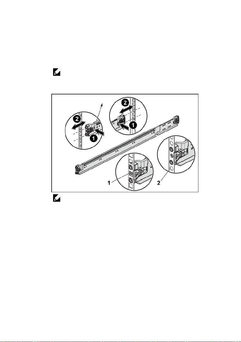
1
Push on the latch release buttons on the midpoints of the end piece to
open the rail latches. See Figure 1.
2
Align the end pieces of the rails on the vertical rack flanges to seat the
pegs in the bottom hole of the first U and the top hole of the second
U.
NOTE:
The rails can be used in both square-hole (item 1 in the following figure)
and round-hole racks (item 2 in the following figure).
Figure 1. Pushing the Latch Release Buttons
NOTE:
To remove the rails, push on the latch release button on the midpoints
of the end piece and unseat each rail.
Getting Started With Your Sy stem | 4
Page 7

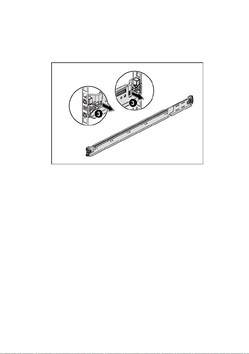
3
Engage the end of the rails and release the latch release button to have
the latches locked in place. See Figure 2.
Figure 2. Releasing the Latch Release Buttons
Getting Started With Your Sy stem | 5
Page 8

4
On each vertical rack flange on the back, put two screw bases into the
two square holes right above the rail. See Figure 3.
5
Install the chassis stabilizer shipping brackets (optional) on the back
rack flanges.
6
Install and tighten the screws.
NOTE:
To transport systems already installed in the rack, ensure that the two
chassis stabilizer shipping brackets (optional) are in place.
Figure 3. Installing the Chassis Stabilizer Shipping Brackets
Getting Started With Your Sy stem | 6
Page 9
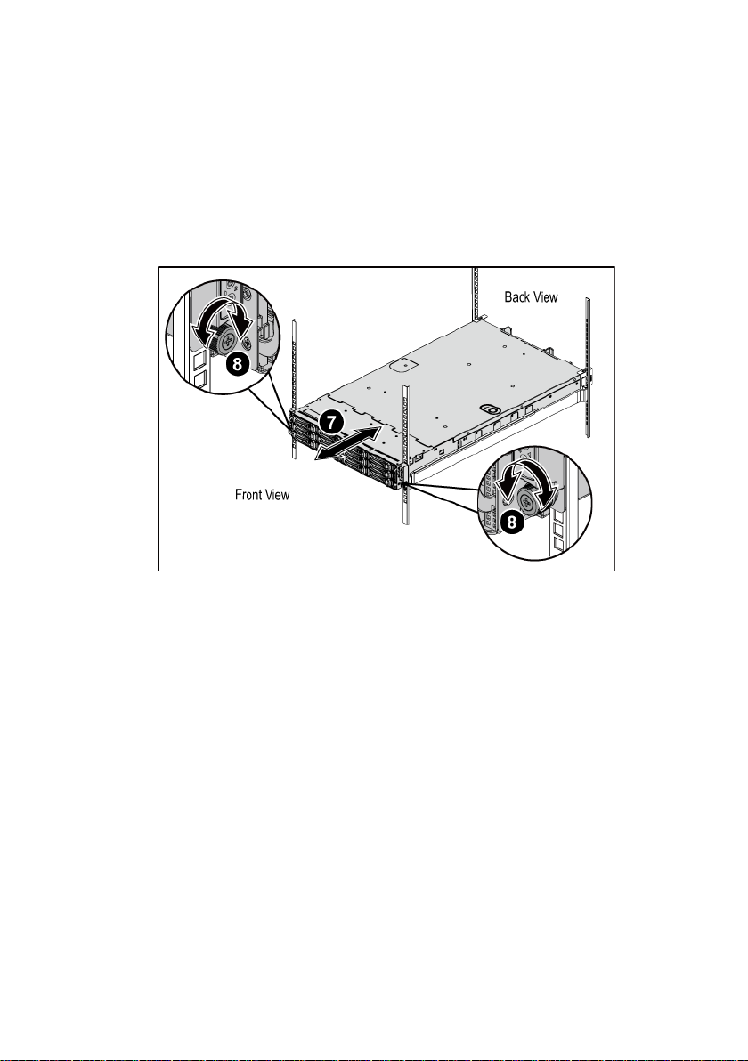
7
Slide the system into the rack. See Figure 4.
8
Tighten the thumbscrews to secure the ears of the system to the front of
the rack flanges.
Figure 4. Installing the Chassis onto the Rack.
Getting Started With Your Sy stem | 7
Page 10
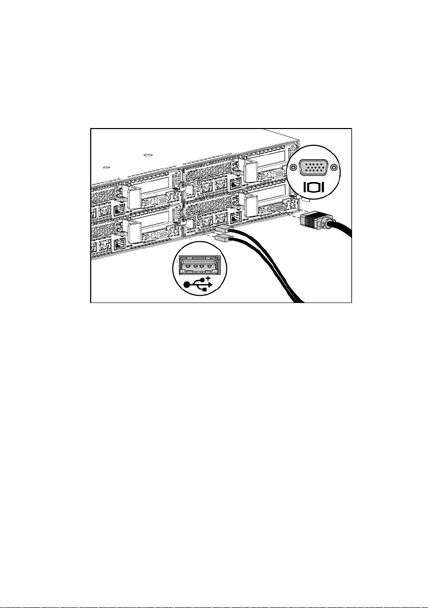
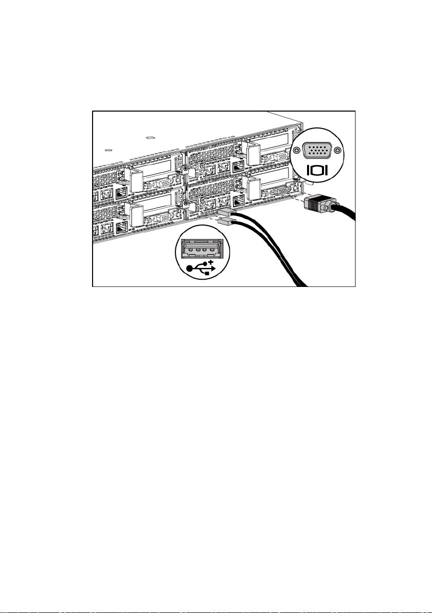
Optional—Connecting the Keyboard, Mouse, and Mon ito r
Figure 5. Optional—Connecting the Keyboard, Mo use and Monitor
Connect the keyboard, mouse, and monitor (optional).
The connectors on the back of your system have icons indicating which cable to
plug into each connector. Be sure to tighten the screws (if any) on the monitor’s
cable connector.
Getting Started With Your Sy stem | 8
Page 11
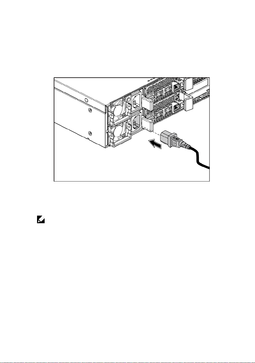
Connecting the Pow er Ca ble (s)
Figure 6. Connecting the Power Cable
Connect the system’s power cable(s) to the system and, if a monitor is used,
connect the monitor’s power cable to the monitor. Plug the other end of the
power cables into a grounded electrical outlet or a separate power source such as
an uninterrupted power supply or a power distribution unit.
NOTE:
Your system can suppor t up to two 1200 W pow er supply uni ts (100-240 VAC
nominal input voltage) or up to two 1 400 W p ower suppl y u nits (2 00-240 VA C n ominal
input voltage).
Getting Started With Your Sy stem | 9
Page 12

Turning on the System
Figure 7. Pressing the Power Button o n the Front of the System
Figure 8. Pressing the Power Button o n the Back of the System
Press the power button(s) either on the front or back of the system. The power
indicators should light green.
Getting Started With Your Sy stem | 10
Page 13

Complete the Operating System Setup
11950 México, D.F.
To install an operating system for the first time, see the installation and
configuration documentation for your operating system. Be sure the operating
system is installed before installing hardware or software not purchased with the
system.
NOTE:
See dell.com/ossupport for the latest information on supported
operating systems.
Other Information You May Need
The Hardware Owner’s Manual provides information about system features and
describes how to troubleshoot the system and install or replace system
components. This document is available at
Dell systems management application documentation provides information
about installing and using the systems management software. This document is
available online at
WARNING: See the safety and regulatory information that shipped with your
system. Warranty information may be included within this document or as a
separate do cu men t.
dell.com/support/manuals
dell.com/support/manuals
NOTE:
Always check for updates on
updates first because they often supersede information in other documents.
dell.com/support/manuals
.
and read the
.
NOM Information (Mexico Only)
The following information is provided on the device described in this document
in compliance with the requirements of the official Mexican standards (NOM):
Importer Dell Inc. de México, S.A. de C.V.
Paseo de la Reforma 2620-11° Piso
Col. Lomas Atlas
Model number B08S
Getting Started With Your Sy stem | 11
Page 14

Supply voltage 100-240 V AC with 1200 W Power
Supply Unit
Unit
Power
AC power supply (per power supply)
Wattage
1200 W
Heat dissipation
4016.251 BTU/hr maximum
cannot exceed 35 Amps (peak).
Wattage
1400 W
current: 9.0 Amps
Heat dissipation
6024.376 BTU/hr maximum.
cannot exceed 25 Amps (peak).
Supply Unit
200-240 V AC with 1400 W Power
Frequency 50/60 Hz
Current consumption
12-8 Amps with 1200 W Power Supply
Unit
9 Amps with 1400 W Power Supply
Technical Specifications
NOTE:
The system doesn’t suppor t a mixed installation of 1200 W and 1400 W power supply
units.
NOTE:
Both the 1200 W and 1400 W PSUs are hot swappable, and they can support hot swap in
any condition if the system has the power throttling feature.
Voltage 100-240 VAC, 50/60 Hz, maximum input
current: 12.0-8.0 Amps
NOTE:
For 1200 W power supply, output 1200 W is for
high line (input 200-240 VAC), output 1023 W is for low
line (input 100-120 VAC).
Maximum inrush current Initial In-rush Current cannot exceed 55
Amps (peak). Secondary In-rush Current
Voltage 200-240 VAC, 50-60 Hz, maximum input
Maximum in-rush current Initial In-rush Current cannot exceed 55
Getting Started With Your Sy stem | 12
Amps (peak). Secondary In-rush Current
Page 15

Battery (per sy s tem board)
System battery
CR 2032 3.0-V lithium ion coin cell
Physical
Height
8.68 cm (3.42 in)
Width
44.8 cm (17.6 in)
Depth
79.0 cm (31.1 in)
Weight (maximum
15.1 kg (33.29 lb) (with 3.5” HDD bay)
Environmental
Temperature
hour
Relative humidity
humidity gradation of 10% per hour
Storage
5% to 95% (noncondensing)
Maximum vibration
Operating
0.26 Grms at 5–350 Hz
configuration)
41 kg (90.38 lb) (with 12*3.5” HDD)
39 kg (86.00 lb) (with 24*2.
5” HDD)
Weight (empty) 15.7 kg (34.61 lb) (with 2.5” HDD bay)
NOTE:
For additional i nformat ion about environmental measurements for specific system
configurations, see
www.dell.com/environmental_datasheets
.
Operating 10° to 35°C (50° to 95°F) with a maximum
temperature gradation of 10°C per hour
NOTE:
For altitudes above 2950 feet, the maximum
operating temperature is derated 1°F/550 ft.
CAUTION:
and hard drives supported on 1U and 2U node
configurations, with 130 W (4 and 8 core) and 135 W
processors, depends on the power supply installed.
The maximum number of memory modules
Storage –40° to 65°C (–40° to 149°F) with a
maximum temperature gradation of 20°C per
Operating 20% to 80% (noncondensing) with a maximum
Storage 1.88 Grms at 10–500 Hz for 15 min
Getting Started With Your Sy stem | 13
Page 16

Maximum sho ck
Operating One shock pulse in the positive z axis
for 2.6 ms in the operational orientation
at 235 inches/second (597 centimeters/second)
Altitude
Operating
-15.2 to 3,048 m (-50 to 10,000 ft.)
Storage
-15.2 to 10,668 m (-50 to 35,000 ft.)
Airborne Contaminant Level
Class
G1 as defined by ISA-S71.04-1985
(one pulse on each side of the system) of 31 G
Storage Six consecutively executed shock pulses in the
positive and negative x, y, and z axes
(one pulse on each side of the system) of 71 G
for up to 2 ms;
Six consecutively executed shock pulses in the
positive and negative x, y, and z axes
(one pulse on each side of the system) of 27 G
faired square wave pulse with velocity change
Getting Started With Your Sy stem | 14
Page 17

Dell PowerEdge
C6220 II
系统
使用入门
Page 18

注、小心和警告
注:
小心:“小心”表示如果不遵循说明,就有可能损坏硬件或导致数据丢失。
警告:“警告”表示可能会导致财产损失、人身伤害甚至死亡。
“注”表示可以帮助您更好地使用计算机的重要信息。
______________
本文档中的信息如有更改,恕不另行通知。
© 2013 Dell Inc.
未经 Dell Inc. 书面许可,严禁以任何形式复制这些材料。
本文中使用的商标:Dell™、DELL 徽标和 PowerEdge™ 是 Dell Inc. 的商标。Intel®
和 Intel® Xeon® 是 Intel Corporation 在美国和其他国家或地区的注册商标。Red Hat
Enterprise Linux® 和 Enterprise Linux® 是 Red Hat, Inc. 在美国和/或其他国家的注册
商标。Novell® 和 SUSE™ 分别是 Novell Inc. 在美国和其他国家/地区的注册商标和
商标。Citrix® 和 XenServer® 是 Citrix Systems, Inc. 在美国和/或其他国家/地区的注
册商标或商标。VMware® 是 VMware, Inc. 在美国或其他国家/地区的注册商标。
本出版物中可能使用其他商标和产品名称来指拥有相应商标和产品名称的公司或其
产品。Dell Inc. 对不属于自己的商标和商品名称不拥有任何所有权。
保留所有权利。
管制型号 B08S
2013 年 5 月 P/N MKP4R Rev. A00
Page 19

小心:受限访问位置
警告:执行下列步骤之前,请先阅读并遵循系统随附的安全说明。
警告:需要提起系统时,请让其他人进行协助。为避免受伤,请勿尝试独自
提起系统。
警告:系统并未固定到机架上,也并没有安装在滑轨上。为避免人身伤害或
系统损坏,在安装和拆卸时,必须给系统提供足够的支撑。
警告:为避免可能的电击伤害,安装机架时需要第三根导线的安全接地线。
机架设备必须为系统提供足够的通风以维持适当的冷却效果。
小心:在方孔机架中安装导轨时,务必确保方形插销穿过方孔。
此服务器仅用于安装在由 IEC 60950-1: 2001 的 Cl. 1.2.7.3 定义的满足下列两个条
件的受限访问位置中:
• 仅维修人员或对该位置施加限制的理由以及应当采取的防备措施已完全领
会的用户,方可对此服务器进行访问。
• 访问是通过使用工具或锁和钥匙,或其它安全手段来实现,并且由负责该
位置的管理机构来控制。
安装和配置
安装免工具拆装导轨解决方案
系统使用入门 | 17
Page 20
1 请拔起尾段正中央的闩锁释放按钮以打开滑轨闩锁。请参阅图 1。
注:
注:
2 在机架垂直凸缘上对齐滑轨的尾段,将插销分别插入第一个 U 型螺栓
的底孔中和第二个 U 型螺栓的顶孔中。
滑轨在方孔机架(下图中的项目 1)和圆孔机架(下图中的项目 2)
中均可使用。
图 1. 按压闩锁释放按钮
闩锁释放按钮
正面视图
要卸下滑轨,请按压尾段正中央的闩锁释放按钮并取出每根滑轨。
背面视图
系统使用入门 | 18
Page 21
3 固定滑轨尾端并松开闩锁释放按钮以将闩锁锁定入位。请参阅图 2。
图 2. 松开闩锁释放按钮
背面视图
正面视图
系统使用入门 | 19
Page 22

4 在背面每个垂直机架凸缘上,将两个螺钉底座放入滑轨正上方的两个方
注:
背面视图
孔内。请参阅图 3。
5 将运输时稳固机箱的支架(可选)安装到背面机架凸缘上。
6 安装并拧紧螺钉。
要运输已经安装在机架上的系统,请确保两个运输时稳固机箱的支
架到位(可选)。
图 3. 安装运输时稳固机箱的支架
系统使用入门 | 20
Page 23

7 将系统滑入到机架中。请参阅图 4。
8 拧紧指旋螺钉,将系统的耳柄固定到机架凸缘正面。
图 4. 安装机箱到机架上。
背面视图
正面视图
系统使用入门 | 21
Page 24
可选 — 连接键盘、鼠标和显示器
图 5. 可选 — 连接键盘、鼠标和显示器
连接键盘、鼠标和显示器(可选)。
系统背面的连接器附有图标,这些图标指示了要插入每个连接器的电缆。确保拧
紧显示器电缆连接器上的螺钉(如果有)。
系统使用入门 | 22
Page 25

连接电源电缆
注:
图 6. 连接电源电缆
将系统电源电缆连接至系统,如果使用显示器,则将显示器电源电缆连接至显示
器。将电源电缆的另一端插入接地的电源插座或单独的电源,例如不间断电源设
备或配电装置。
您的系统可支持多达两个 1200 W 电源设备装置(100-240 V 交流额定输入
电压)或多达两个 1400 W 电源设备装置(200-240 V 交流额定输入电压)。
系统使用入门 | 23
Page 26

开启系统
图 7. 按下系统正面的电源按钮
图 8. 按下系统背面的电源按钮
按下系统正面或背面的电源按钮。电源指示灯应呈绿色亮起。
系统使用入门 | 24
Page 27

完成操作系统安装
注:
警告:请参阅系统附带的安全与管制信息。保修信息可能包括在该说明文件中,
也可能作为单独的说明文件提供。
注:
11950 México, D.F.
200-240 V
1400 W
9
1400 W
第一次安装操作系统时,请参阅操作系统的安装和配置说明文件。请确保先安装
操作系统,然后再安装并非随系统购买的硬件或软件。
有关支持的操作系统的最新信息,请参阅 dell.com/ossupport。
可能需要的其它信息
硬件用户手册
或更换系统组件。此说明文件可从 dell.com/support/manuals 获得。
Dell 系统管理应用程序说明文件提供了有关如何安装和使用系统管理软件的信息。
此说明文件可从 dell.com/support/manuals 在线获取。
提供了有关系统功能的信息,并说明了如何排除系统故障以及安装
请经常访问 dell.com/support/manuals 以获得更新,并首先阅读这
些更新,因为这些更新通常会取代其它说明文件中的信息。
NOM 信息(仅限于墨西哥)
根据墨西哥官方标准 (NOM),本说明文件中述及的的设备上必须提供以下信息:
进口商 Dell Inc. de México, S.A. de C.V.
Paseo de la Reforma 2620-11° Piso
Col. Lomas Atlas
型号
电源电压 100-240 V 交流,带 1200 W 电源设备装置
频率
B08S
50/60 Hz
交流,带
电源设备装置
电流消耗
12-8 安培,带 1200 W 电源设备装置
安培,带
电源设备装置
系统使用入门 | 25
Page 28

技术规格
电源
注:
注:
交流电源设备(每个电源设备)
1200 W
注:
4016.251 BTU/hr
35 Amps
9.0 安培
6024.376 BTU/hr
25
电池(每个系统板)
CR 2032 3.0 V
物理规格
8.68
3.42
44.8
17.6
79.0
31.1
系统不支持混合 安装 1200 W 和 1400 W 电源设备装置。
1200 W 和 1400 W PSU 均为热置换式,如果系统具有功率限额功能,则其可支持在
任何情况下的热置换。
功率
电压 100-240 V 交流, 50/60 Hz,最大输入电流:12.0-
8.0 安培
对于 1200 W 电源设备,输出 1200 W 是用于高
压线路(输入 200-240 VAC),输出 1023 W 是用于
低压线路(输入 100-120 VAC)。
散热
,最大值
最大涌入电流 初始涌入电流不能超过 55 Amps(峰值)。
(峰值)。
功率
电压
散热
二次涌入电流不能超过
1400 W
200-240 V 交流,50-60 Hz,最大输入电流:
,最大值。
最大涌入电流 初始涌入电流不能超过 55 安培(峰值)。
系统电池
高度
宽度
厚度
二次涌入电流不能超过
币形锂电池
厘米(
厘米(
厘米(
英寸)
英寸)
英寸)
安培(峰值)。
重量(最大配置) 41 千克 (90.38 磅)(配有 12*3.5” HDD)
39 千克 (86.00 磅)(配有 24*2.5” HDD)
系统使用入门 | 26
Page 29

重量(空置) 15.7 千克 (34.61 磅)(配有 2.5” HDD 托架)
15.7 千克 (33.29 磅)
3.5” HDD
环境参数
注:
温度
注:
小心:
20°C
相对湿度
10%
5% 至 95%
最大振动
5–350 Hz 时为 0.26 Grms
最大撞击
2.6 毫秒
(配有
有关特定系统配置的环境测量值的更多信息,请访问
www.dell.com/environmental_datasheets。
托架)
运行时 10 °C 至 35 °C(50 °F 至 95 °F),最大温度变
化梯度为每小时 10 °C
海拔高度在 2950 英尺以上时,最高操作温度降
幅为 1 °F/550 ft。
在 1U 和 2U 节点配置(带有 130 W [4 和 8 核]
和 135 W 处理器)上支持的内存模块和硬盘的最大数
量,取决于所安装的电源设备。
存储 -40° 至 65°C(-40° 至 149°F),每小时最大温
差不超过
运行时 20% 至 80%(非冷凝),最大湿度变化为每小时
存储时
运行时
存储 在 10 - 500 Hz、1.88 Grms 时,可持续 15 分钟
运行时 在 z 轴正方向一个 31 G 的撞击脉冲(系统每一
(非冷凝)
面各承受一个脉冲),在运行方向上可持续
系统使用入门 | 27
Page 30

存储时 x、y 和 z 轴正负方向上可承受连续六个 71 G 的
235 英寸/秒(597 厘米/秒)
气载污染物级别
G1
ISA-S71.04-1985
撞击脉冲(系统每一面承受一个脉冲),最长可
持续 2 毫秒;
x、y 和 z 轴正负方向上可承受连续六个 27 G 正
弦波脉冲的撞击脉冲(系统每一面承受一个脉
冲),速度变化为
分类
(根据
定义的标准)
系统使用入门 | 28
Page 31

Dell PowerEdge
C6220 II
Mengaktifkan
Sistem Anda
Page 32

Catatan, Perhatian, dan Peringatan
CATATAN:
mengoptimalkan penggu naan komputer Anda .
PERHATIAN : PER HA TIA N men un ju kkan keru sa kan pote nsi al pad a
perangka t ker as at au ke hil ang an da ta jik a And a tida k mengiku ti instru ksi
yang diberikan.
PERINGATAN: PERINGATAN menunjukkan potensi terjadinya kerusakan
properti, ced era, atau k em atia n.
CATATAN menunjukkan informasi penting yang membantu Anda
______________
Informasi dalam dokumen ini dapat diubah tanpa pemberitahuan sebelumnya.
© 2013 Dell Inc. Hak cipta dilindungi undang-undang.
Dilarang keras memperbanyak material ini dalam cara apa pun tanpa izin tertulis Dell Inc.
Merek dagang yang digunakan dalam teks ini: Dell™, logo DELL, dan PowerEdge™
merupakan merek dagang dari Dell Inc. Intel® dan Intel® Xeon® merupakan merek
dagang terdaftar dari Intel Corporation di AS dan negara lain. Red Hat Enterprise Linux®
dan Enterprise Linux® merupakan merek dagang terdaftar dari Red Hat, Inc. di Amerika
Serikat dan/atau negara-negara lainnya. Novell® merupakan merek dagang terdaftar dan
SUSE™ merupakan merek dagang dari Novell Inc. di Amerika Serikat dan negara-negara
lainnya. Citrix® dan XenServer® merupakan merek dagang terdaftar atau merek dagang
dari Citrix Systems, Inc. di Amerika Serikat dan/atau negara-negara lainnya. VMware®
merupakan merek dagang terdaftar dari VMWare, Inc. di Amerika Serikat dan/atau
negara-negara lainnya.
Merek dagang dan nama dagang lain yang mungkin digunakan dalam dokumen ini
mengacu ke entitas yang mengaku memiliki merek dan nama produk mereka. Dell Inc.
tidak mengklaim kepemilikan dari merek dagang dan nama dagang selain miliknya sendiri.
Model Resmi B08S
Mei 2013 No. Komp. MKP4R Rev. A00
Page 33

PERHATIAN: Lokasi Akses Terbatas
PERINGATAN: Sebelum menjalank an prosedur berikut, tin jau dan ikuti p e tu njuk
Server ini ditujukan hanya untuk pemasangan di lokasi akses terbatas seperti
yang ditentukan pada Cl. 1.2.7.3 of IEC 60950-1: 2001 di mana kedua kondisi
ini diterapkan:
•
Akses hanya dapat diperoleh oleh staf servis atau oleh pengguna ang telah
diinformasikan mengenai alasan untuk pembatasan yang diterapkan pada
lokasi dan mengenai tindakan pencegahan yang harus diambil.
•
Akses adalah melalui penggunaan alat atau pengunci dan tombol, atau
unsur keamanan lain, dan dikontrol oleh otoritas yang bertanggung jawab
terhadap lokasi.
Pemasangan dan Konfigurasi
keselamatan yang disertakan dengan sistem.
Menginstal Solusi Rel Tanpa Alat
PERINGATAN: Jika Anda perlu men gangkat sis te m , m intalah orang la i n
untuk membantu Anda. Untuk men ceg ah ced er a, jan g an ang ka t siste m
seorang diri.
PERINGATAN: Sistem tidak dipasang pada rak at au dipasang p ada rel.
Untuk mencegah ced era atau kerusakan sistem, A n da harus meno pang
rak sistem dengan benar selama memasang dan melepas sistem.
PERINGATAN: Untuk mencegah bahaya seng a tan listrik yang mungkin
terjadi, konduktor grounding keselamatan kabel ketiga diperlukan untuk
memasang rak. Perleng k ap a n rak harus me mu n gkinkan alir an u dara yang
mencukupi untuk sistem guna mengatur pendinginan yang benar.
PERHATIAN: Ketika menginstal rak pada rak dengan lubang persegi,
penting u n t uk memastik an bahwa pasa k persegi mene mb us lubang
persegi.
Mengaktifkan Sistem Anda | 31
Page 34

1
Tampilan belak an g
Tombol Pele pas Kait
Tampilan depa n
Tarik tombol pelepas kait pada titik tengah pada bagian ujung untuk
membuka kait rel. Lihat Gambar 1.
2
Sesuaikan bagian ujung rel pada flens rak vertikal untuk
mendudukkan pasak pada lubang bawah U pertama dan lubang atas
U kedua.
CATATAN:
gambar berikut) dan ra k lubang bulat (butir 2 pada gambar berikut).
Rel dapat digu nakan pad a rak lubang persegi (bu tir satu pada
Gambar 1. Dorong Tombol Pelepas Kait
CATATAN:
ke bagian ujung dan geser posisi setiap rel.
Untuk melepa skan rel, tarik t ombol pelep as kait pada titik tengah
Mengaktifkan Sistem Anda | 32
Page 35

3
Tampilan depa n
Tampilan belak an g
Tarik bagian ujung rel dan lepaskan tombol pelepas kait untuk
mengunci kait di tempatnya. Lihat Gambar 2.
Gambar 2. Lepaskan Tombol Pelepas Kait
Mengaktifkan Sistem Anda | 33
Page 36

4
Tampilan depa n
Pada setiap flensa rak vertikal di bagian belakang, letakkan dua
dasar sekrup ke dalam dua lubang persegi di atas rel. Lihat Gambar 3.
5
Pasang braket shipping stabilisator sasis (opsional) di bagian
belakang flensa rak.
6
Pasang dan kencangkan bautnya.
CATATAN:
pastikan bahwa dua braket shipping stabilisator sasis (opsional) tetap
terpasang pada tempatnya.
Untuk mengirimkan sistem yang telah terpasang di dalam rak,
Gambar 3. Memasang Braket Shipping Stabilisator Sasis
Mengaktifkan Sistem Anda | 34
Page 37

7
Tampilan belak an g
Tampilan depa n
Geser sistem ke dalam rak. Lihat Gambar 4.
8
Kencangkan baut thumbscrews untuk mengencangkan bagian telinga
sistem ke bagian depan flensa rak.
Gambar 4. Memasang Sasis ke Rak.
Mengaktifkan Sistem Anda | 35
Page 38

Opsional—Meny ambungk an k e Ke yboard, Mouse, dan M on itor
Gambar 5. Opsional – Menyambungka n ke Keyboard, Mous e, dan Monitor
Sambungkan keyboard, mouse, dan monitor (opsional).
Konektor di bagian belakang sistem Anda memiliki ikon yang mengindikasikan
kabel mana yang akan disambungkan ke setiap konektor. Pastikan untuk
mengencangkan baut (jika ada) pada konektor kabel monitor.
Mengaktifkan Sistem Anda | 36
Page 39

Menyambungkan Kabel Daya
Gambar 6. Menyambung kan Kabel Daya
Sambungkan kabel daya sistem ke sistem, dan jika monitor digunakan,
sambungkan kabel daya monitor ke monitor. Sambungkan ujung lain kabel
daya ke outlet listrik yang dihubungkan ke ground atau sumber daya seperti
UPS (uninterrupted power supply) atau PDU (power distribution unit).
CATATAN:
1.200 W (dengan voltase input sebesar 100-240 VAC) atau hingga dua unit catu daya
( dengan voltase input sebesar 200-240 VAC).
Sistem Anda dapat mendukung hingga dua unit catu daya berkekuatan
Mengaktifkan Sistem Anda | 37
Page 40

Mengaktifkan Sistem
Gambar 7. Menekan Tombol Daya pada Bagian Depan Sistem
Gambar 8. Menekan Tombol Daya pada Bagian Belakang Sistem
Tekan tombol daya di bagian depan atau belakang sistem. Indikator daya akan
menyala dan berwarna hijau.
Mengaktifkan Sistem Anda | 38
Page 41

Selesaikan Pengaturan Sistem Pengoperasian
Untuk menginstal sistem pengoperasian untuk pertama kali, lihat dokumentasi
pemasangan dan konfigurasi untuk sistem pengoperasian Anda. Pastikan sistem
pengoperasian diinstal sebelum memasang perangkat keras atau menginstal
perangkat lunak yang tidak dibeli dengan sistem.
CATATAN:
pengoperasian yang di dukung .
Lihat
dell.com/ossupport
untuk infor masi terkini tentang sist em
Informasi Lain yang Anda Perlukan
Petunjuk Penggunaan Perangkat Keras unt uk P e mil i k menyediakan informasi
mengenai fitur sistem dan menguraikan bagaimana cara menelusuri kesalahan
sistem dan memasang atau mengganti komponen sistem. Dokumen ini tersedia
secara online di situs
Dokumentasi aplikasi manajemen sistem Dell menyediakan informasi tentang
penginstalan dang penggunaan perangkat lunak manajemen sistem. Dokumen
ini tersedia secara online di situs
PERINGATAN: Lihat informasi keselamatan dan p eraturan yan g d isertakan
dengan si stem And a. Informasi garan si mu n gkin diserta k an dalam dokum en ini
atau sebagai dokumen terpisah.
dell.com/support/manuals
dell.com/support/manuals
CATATAN:
baca update terlebi h dah ulu karena b iasany a upd ate i ni a kan meng ganti kan
informasi dalam dok umen lain.
Selalu periksa update di situs
dell.com/support/manuals
.
.
dan
Mengaktifkan Sistem Anda | 39
Page 42

Informasi NOM (Hanya untuk Meksiko)
11950 México, D.F.
200 – 240 V AC dengan Unit Catu Daya 1.400 W
9 Amps dengan Unit Catu Daya 1.400 W
Daya
Catu daya AC (per catu daya)
Daya Listrik
1.200 W
Penghilangan panas
maksimal 4016,251 BTU/jam
Informasi berikut disediakan untuk perangkat yang dijelaskan dalam dokumen
ini sesuai dengan persyaratan standar resmi Meksiko (NOM):
Importir Dell Inc. de México, S.A. de C.V.
Paseo de la Reforma 2620-11° Piso
Col. Lomas Atlas
Nomor model: B08S
Tegangan suplai 100 – 240 V AC dengan Unit Catu Daya 1.200 W
Frekuensi 50/60 Hz
Konsumsi arus 12 – 8 Amps dengan Unit Catu Daya 1.200 W
Spesifikasi Teknis
CATATAN:
unit catu daya 1.400 W.
CATATAN:
dapat mendukung hot swap dalam kondisi apa pun jika sistem memiliki fitur pengendalian
(throttling) daya.
Tegangan 100 – 240 VAC, 50/60 Hz, arus input maksimum:
Mengaktifkan Sistem Anda | 40
Sistem tidak mendukung instalasi gabungan antara unit catu daya 1.200 W dengan
Unit catu daya 1.200 W dan 1.400 W bersifat swappable, dan kedua catu daya ini
12.0 – 8.0 Amps
CATATAN:
output 1 200 W untuk tegangan tinggi (input 200 –
240 VAC), output 1.023 W untuk tegangan rendah
(input 100 – 120 VAC).
Untuk catu daya sebesar 1.200 W,
Page 43

Arus masuk maksimal Lonjakan Arus Awal tidak boleh melebihi
boleh melebihi 35 Amps (peak).
Daya Listrik
1.400 W
9.0 Amps
Penghilangan panas
maksimal 6024,376 BTU/jam
boleh melebihi 25 Amps (peak).
Baterai (per board sistem)
Baterai sistem
Baterai sel lithium berbentuk koin CR 2032 3,0-V
Fisik
Tinggi
8,68 cm (3,42 inci)
Lebar
44,8 cm (17,6 inci)
Panjang
79,0 cm (31,1 inci)
15,1 kg (33,29 lb) (dengan 3.5” HDD bay)
Lingkungan
Suhu
55 Amps (peak). Lonjakan Arus Sekunder tidak
Tegangan 200 – 240 VAC, 50/-60 Hz, arus input maksimum:
Arus masuk maksimal
Berat (konfigurasi maksimal)
Berat (k
osong)
CATATAN:
sistem spesifik, lihat
Untuk informasi tambahan mengenai pengukuran lingkungan untuk konfigurasi
www.dell.com/environmental_datasheets
Pengoperasian
Lonjakan Arus Awal tidak boleh melebihi
55 Amps (peak). Lonjakan Arus Sekunder tidak
41 kg (90,38 lb) (dengan 12*3.5” HDD)
39 kg (86,00 lb) (dengan 24*2.5” HDD)
7 kg (34,61 lb) (dengan 2.5” HDD bay)
15,
.
10° hingga 35°C (50° hingga 95°F) dengan
gradasi suhu maksimal 10°C per jam
CATATAN:
suhu pengoperas ian maksi mal d iturun kan menjadi
1°F/550 kaki.
PERHATIAN:
disk yang didukung pada konfigurasi node 1U dan 2 U,
dengan prosesor 130 W (dengan inti 4 atau 8) dan 135 W,
tergantung pada catu daya yang dipasang.
Untuk ketinggian di atas 2.950 kaki,
Jumlah maksimal modul memory dan hard
Mengaktifkan Sistem Anda | 41
Page 44

Penyimpanan
gradasi suhu maksimal 20°C per jam
Kelembaban relatif
kelembaban maksimal 10% per jam
Penyimpanan
5% hingga 95% (nonkondensasi)
Getaran mak s imal
Pengoperasian
0,26 Grm pada 5
–
350 Hz
Penyimpanan
1,88 Grm pada 10
–
500 Hz selama 15 menit
Getaran maksimal
2,6 ms dalam arah pengoperasian
kecepatan 235 inci/detik (597cm/detik)
Ketinggian
Pengoperasian
-15,2 hingga 3.048 m (-50 hingga 10.000 kaki)
Penyimpanan
-15,2 hingga 10.668 m (-50 hingga 35.000 kaki)
Level Kontaminasi Melalui Udara
Kelas
G1 sebagaimana ditentukan oleh ISA-S71.04-1985
-40° hingga 65°C (-40° hingga 149°F) dengan
Pengoperasian
Pengoperasian Satu pulsasi guncangan pada sumbu z positif
Penyimpanan Enam pulsasi getaran yang dijalankan berurutan
20% hingga 80% (nonkondensasi) dengan gradasi
(satu pulsasi di setiap sisi sistem) dari 31 G selama
pada sumbu x, y, dan z positif dan negatif
(satu pulsasi di setiap sisi sistem) pada 71 G hingga
selama 2 mdet;
Enam pulsasi guncangan yang dijalankan berturutan
pada sumbu x, y, dan z positif dan negatif
(satu pulsasi di setiap sisi sistem) dari 27 G pulsasi
gelombang persegi normal dengan perubahan
Mengaktifkan Sistem Anda | 42
Page 45

Dell PowerEdge
C6220 II
はじめに
Page 46

メモ、注意、警告
メモ:コンピュータを使いやすくするための重要な情報を説明しています。
注意:手順に従わない場合、ハ ードウェアの損傷やデータの 損失が発生する可能性があるこ とを示します。
警告:物的損害、けが、または 死亡の原因となる可能性があ ることを示しています。
______________
本文書にある情報は予告なく変更される場合があります。
© 2013
すべての著作権は Dell Inc. にあります。
Dell Inc. の書面による許可のない複写は、いかなる形態においても厳重に禁止されています。
本書に使用されている商標:Dell™、DELL ロゴ、および PowerEdge™ は Dell Inc. の商標です。
Intel® および Intel® Xeon® は米国およびその他の国における Intel Corporation の登録商標です。
Red Hat Enterprise Linux® および Enterprise Linux® は、米国および/ またはその他の国おける
Red Hat, Inc. の登録商標です。Novell® は米国およびその他の国における Novell Inc. の登録商
標であり、
SUSE™ は米国およびその他の国における同社の商標です。Citrix® および
XenServer® は米国および / またはその他の国おける Citrix Systems, Inc. の登録商標または商標
VMware® は米国またはその他の国における VMware, Inc. の登録商標または商標です。
です。
本書では、商標および名称、または製品の権利を主張する事業体を表すために、その他の商標および
商号が使用されている場合があります。
Dell Inc. に帰属するものではありません。
Dell Inc. 所有の商標および商号以外のものは、一切
規制モデル B08S
2013 年 5 月 P/N MKP4R Rev. A00
Page 47

注意:立入制限区域
このサーバーは、
のみを対象としています。これには、次の両条件が適用されます。
•
•
取り付けと設定
ツールレスレールソリューションの取り付け
IEC 60950-1: 2001、Cl. 1.2.7.3
に定義された立入制限区域における設置
この区域への立ち入りは、その場所に適用された制限の理由、および講じる必要のある予防
措置についての指導を受けた保守担当者またはユーザーのみに限定される。
この区域への立ち入りは、道具もしくは施錠、またはその他のセキュリティ手段を使用して行わ
れ、当区域に対する責任を負う主管者によって制御される。
警告:次の手順を実行する前に 、システムに付属の安全上の 注意をよく読んで指示に従って ください。
警告: システムを持ち上げる必要が ある場合は、他の人に援助を依頼 してください。けがを防ぐ ため、シ
ステムをひとりで持ち上げよう としないでください。
警告: システムはラックに固定され ておらず、レールにも取り付けら れていません。けがまたは システム
の損傷を防止するため、取り付 けと取り外しの際にはシステ ムを十分に支える必要がありま す。
警告: 感電の可能性を避けるため、 ラックの取り付けには第
却効果を維持するため、ラック 装置はシステムに対して十分 な通気を提供する必要がありま す。
注意:角穴ラックにレールを取 り付ける時は、角型ペグを角 穴に確実に挿入することが重要 です。
3 種電力保安接地線が必要です 。適切な冷
はじめに | 45
Page 48

1
前面図
背面図
末端部の中間点にあるラッチリリースボタンを押してレールラッチを開きます。図
照してください。
2
レールの末端部を垂直ラックフランジに合わせ、最初の
U
の最上部の穴にペグを装着します。
メモ:レールは角穴ラック(下図のアイテム
用することができます。
図
1.
ラッチリリースボタンを押す
リリースラッチボタン
U の最下部の穴と、二番目の
1)および丸穴ラック(下図のアイテム
1 を参
2)の両方に使
メモ:レールを取り外すには、末端部の中間点にあるラッチリリースボタンを押して、各レールを外
します。
はじめに | 46
Page 49

3
背面図
レールの末端をはめ込み、ラッチリリースボタンを放してラッチを所定の位置にロックし
ます。図
2 を参照してください。
図
2.
ラッチリリースボタンを放す
前面図
はじめに | 47
Page 50

4
背面図
背面の各垂直ラックフランジで、2 個のねじ込口金をレールのすぐ上にある
穴に差し込みます。図
5
背面ラックフランジにシャーシスタビライザ配送用ブラケット(オプション)を取り付けます。
6
ネジを取り付けて締めます。
メモ:ラックに取り付け済みのシステムを運搬するには、2 個のシャーシスタビライザ配送用ブラケ
ット(オプション)が所定の位置にあることを確認してください。
3 を参照してください。
図
3.
シャーシスタビライザ配送用ブラケットの取り付け
2 つの角
はじめに | 48
Page 51

7
システムをラックに挿入します。図
8
蝶ネジを締め、システムの両耳をラックフランジの前面に固定します。
図
4.
ラックへのシャーシの取り付け
前面図
4 を参照してください。
背面図
はじめに | 49
Page 52

オプション—キーボード、マウス、およびモニタの接続
図
5.
オプション
キーボード、マウス、およびモニタ(オプション)を接続します。
システム背面のコネクタには、各コネクタにどのケーブルを差し込むかを示すアイコンがあります。
モニタのケーブルコネクタにネジがある場合はそれらを締めるようにしてください。
— キーボード、マウス、およびモニタの接続
はじめに | 50
Page 53

電源ケーブルの接続
図
6.
電源ケーブルの接続
システムの電源ケーブルをシステムに接続し、モニタを使用している場合はモニタの電源ケーブルを
モニタに接続します。電源ケーブルのもう一端を接地したコンセントまたは個別の電源
装置または配電ユニット)に差し込みます。
メモ:お使いのシステムは最大
1400 W
電源装置 (
の
200-240 VAC
2 台の
1200 W
電源装置 (
公称入力電圧)をサポートします。
100-240 VAC
公称入力電圧)、または最大
(無停電電源
2 台
はじめに | 51
Page 54

システムへの電源投入
図
7.
システム前面の電源ボタンを押す
図
8.
システム背面の電源ボタンを押す
システムの前面または背面いずれかの電源ボタンを押します。電源インジケータが緑色に点灯します。
はじめに | 52
Page 55

オペレーティングシステムのセットアップの完了
オペレーティングシステムを初めてインストールするには、お使いのオペレーティングシステムのインス
トールおよび設定マニュアルを参照してください。システムとは別途に購入したハードウェアまたはソフ
トウェアをインストールする前に、オペレーティングシステムがイン ストール済みであること を確認してく
ださい。
メモ:対応オペレーティングシステムに関する最新情報については、
を参照してください。
dell.com/ossupport
その他の必要情報
警告:お使いのシステムに同梱 の安全および認可機関に関す る情報を参照してください。保 証情報は本書に記載
されているか、個別の文書とし て提供されています。
『
Hardware Owner’s Manual
情報が記載されており、システムのトラブルシューティング方法、およびシステムコンポーネントの取り
付け方法や交換方法が説明されています。このマニュアルは
。
手可能です
Dell Systems Management
Software
dell.com/support/manuals
のインストールと使用に関する情報が記載されています。このマニュアルは
メモ:多くの場合、アップデートは他のマニュアルの情報よりも優先されるため、
dell.com/support/manuals
』(ハードウェアオーナ ーズマニュアル)にはシステム機能に関する
dell.com/support/manuals
アプリケーションのマニュアルには、
からオンラインで入手可能です。
でアップデートを常にチェックし、それらを先にお読みください。
Systems Management
から入
はじめに | 53
Page 56

削除
11950 México, D.F.
200~240 VAC
1400 W
9 Amp
AC 電源装置(各電源装置ごと)
1200 W
4016.251 BTU/
35 A
NOM
メキシコ公定基準
に記載されているデバイスについて、以下の情報を提供します。
輸入者
情報(メキシコのみ)
(
the official Mexican standards)(NOM
Dell Inc. de México, S.A. de C.V.
Paseo de la Reforma 2620-11° Piso
Col. Lomas Atlas
)
の要件に従い、このマニュアル
モデル番号
供給電圧
周波数
消費電流
仕様
電源
メモ:本システムでは、
メモ:
どのような条件下でもホットスワップに対応できます。
ワット数
電圧
熱放散
最大突入電流
1200 W
および
1200 W
と
1400 W PSU
1400 W
電源装置ユニットの混在はサポートされていません。
はいずれもホットスワップ対応であり、システムに電力調整機能が備わっていれば、
B08S
1200 W
100
1400 W
電源装置ユニットで
~
240 VAC
電源装置ユニットで
50~60 Hz
1200 W
~240 VAC、50/60 Hz、最大入力電流:
100
12.0
~8.0 Amps
メモ:1200 W 電源装置の場合、出力 1200 W はハイライン
(入力 200~240 VAC)用、出力 1023 W はローライン(入力
~120 VAC)用です。
100
最大
一次突入電流が
入電流が
電源装置ユニットで
電源装置ユニットで
時
55 A
(ピーク)を超えないこと。二次突
(ピーク)を超えないこと。
12~8 Amp
はじめに | 54
Page 57

ワット数
1400 W
9.0 Amp
6024.376 BTU/ 時
25 A
バッテリ(各システム基板ごと)
CR 2032 3.0-V
寸法
8.68 cm(3.42
44.8 cm(17.6
79.0 cm(31.1
15.1 kg(33.29 lb)(3.5
HDD
環境
温度
40° to 149°F)
電圧
熱放散
最大突入電流
200~240 VAC、50/60 Hz
最大
一次突入電流が
二次突入電流が
55 A
、最大入力電流:
(ピーク)を超えないこと。
(ピーク)を超えないこと。
システムバッテリ
縦幅
横幅
長さ
重量(最大構成)
重量(空の状態)
メモ:特定のシステム構成での環境条件の追加情報については、
てください。
動作時
保管時
41 kg
39 kg
15.7 kg
(
90.38 lb)(3.5
(
86.00 lb)(2.5
(
時間当たり最大
1
メモ:高度
1
度下がります
注意:
130W(4
および
2U
ノード構成でのメモリモジュールとハードドライブの最大対応
数は、取り付けられた電源装置によって異なります。
1
時間当たり最大
コイン型リチウムイオン電池
インチ)
インチ)
インチ)
インチ
HDD 12
インチ
HDD 24
34.61 lb)(2.5
www.dell.com/environmental_datasheets
2950
フィート以上で最大使用温度は
。
および
10°C
8
コア)および
インチ
インチ
の温度変化で
HDD
550
135W
プロセッサ搭載時の
台搭載)
台搭載)
ベイ付き)
ベイ付き)
10~
20°C
の温度変化で
-40~65°C (–
を参照し
35°C
フィートごとに華氏
1U
はじめに | 55
Page 58

相対湿度
動作時
20~80 %
5~95 %
最大振動
5~350 Hz
0.26 Grms
最大衝撃
1
1
高度
-15.2~3,048 m(-50~10,000
-15.2~10,668 m(-50~35,000
空気中浮遊汚染物質レベル
ISA-S71.04-1985
G1
保管時
1
時間当たり最大
(結露しないこと)
(結露しないこと)
10
パーセントの湿度変化で
動作時
保管時
動作時
保管時
動作時
保管時
クラス
で
15
分間に
10~
500 Hz
で
1.88 Grms
動作方向において
衝撃パルス(システムの各面に対して
x、y、z
軸の正および負方向に
連続衝撃パルス(システムの各面に対して
x、y、z
軸の正および負方向に
ルス波(
597 cm(597
撃パルス(システムの各面に対して
z 軸の正方向に
インチ)/ 秒の速度変化)の
で規定されている
2.6
2 ミリ秒以下で
27 G
フェアードスクエアパ
パルス)
フィート)
フィート)
ミリ秒で
パルス)
1 パルス)
31 G
71 G
6 連続衝
の
1
の
6
はじめに | 56
Page 59

Dell PowerEdge
C6220 II
시스템
시작하기
Page 60

주, 주의 및 경고
주:
주의: 주의는 지침을 따르지 않을 경우 하드웨어의 손상이나 데이터의 유실을
유발할 수 있는 위험이 있음을 알려줍니다.
경고: 경고는 재산 피해, 부상 또는 사망이 발생될 수 있는 위험 상황을
나타냅니다.
주는 컴퓨터의 활용도를 높이는 데 도움이 되는 중요한 정보입니다.
______________
이 설명서의 정보는 별도의 통보없이 변경될 수 있습니다.
© 2013 Dell Inc.
Dell Inc.의 서면 승인 없이 어떠한 경우에도 이러한 자료를 무단 복제하는 것을
엄격히 금합니다.
본 설명서에 사용된 상표: Dell™, DELL 로고 및 PowerEdge™는 Dell Inc.의
상표입니다. Intel® 및 Intel® Xeon®은 미국 및 다른 국가에 사용되는 Intel
Corporation 의 등록 상표입니다. Red Hat Enterprise Linux® 및 Enterprise Linux®는
미국 및/또는 다른 국가에 사용되는 Red Hat, Inc.의 등록 상표입니다. Novell® 및
SUSE™는 각각 미국 및 다른 국가에 사용되는 Novell Inc.의 등록 상표 및
상표입니다. Citrix® 및 XenServer®는 미국 및/또는 다른 국가에 사용되는 Citrix
Systems, Inc.의 등록 상표 또는 상표입니다. VMware®는 미국 또는 다른 국가에
사용되는 VMWare, Inc.의 등록 상표 또는 상표입니다.
본 출판물에서는 특정 회사의 마크나 제품 이름의 사실성을 입증하기 위해 기타
상표나 상호를 사용할 수도 있습니다. Dell Inc.은 자사 소유 상표 및 상호외에
어떠한 상표 및 상호에 대한 소유권도 없습니다.
저작권 본사 소유.
규정 모델 B08S
2013 년 5 월 P/N MKP4R Rev. A00
Page 61

주의: 제한 접근 지역
경고: 다음 절차를 수행하기 전에 시스템과 함께 제공된 안전 지침을 검토하여
따르십시오.
경고: 시스템을 들어 올릴 때는 다른 사람의 도움을 받아야 합니다. 부상을
방지하려면 혼자서 시스템을 들어 올리지 마십시오.
경고: 시스템은 랙에 들어 맞거나 레일에 장착되지 않습니다. 부상이나 시스템
손상을 방지하려면 설치하거나 분리할 때 시스템을 충분히 지지해야 합니다.
경고: 감전의 위험을 방지하려면 랙 설치 시에 세 번째 와이어 안전 접지
전도체가 필요합니다. 올바른 냉각 상태를 유지하기 위해서는 랙 장비가
시스템에 충분한 공기 흐름을 제공해야 합니다.
주의: 네모 구멍 랙에 레일을 설치할 때는 네모 모양의 페그가 네모 구멍에
매끄럽게 들어가야 합니다.
본 서버는 다음 두 조건이 적용되는
정의된 제한 접근 지역에서만 설치하도록 고안되었습니다
•
해당 지역에 적용되는 제한 사유 및 취해야 할 모든 예방 조치에 관해
지도를 받은 서비스 기술자 또는 사용자만 액세스할 수 있습니다
•
접근은 공구, 자물쇠 및 키 또는 다른 보안 수단을 사용하여
이루어지며, 지역 담당 책임자에 의해 제어됩니다
IEC 60950-1: 2001의 Cl. 1.2.7.3에
.
.
설치 및 구성
도구 없이 레일 솔루션 설치
.
시스템 시작하기 | 59
Page 62

1
주
주:
끝 부분의 중심점에 있는 래치 분리 단추를 눌러 레일 래치를
엽니다. 그림 1을 참조하십시오
2
레일의 끝 부분을 수직 랙 플랜지에 맞추어 첫 번째 U의 아래쪽
.
구멍 및 두 번째 U의 위쪽 구멍에 페그를 장착합니다
.
: 레일은 네모 구멍(다음 그림에서 항목
그림에서 항목
그림
1. 래치 분리 단추
2) 둘 다에
누르기
래치 분리 단추
사용할 수 있습니다
1) 랙과 둥근 구멍 랙(다음
.
후면 모습
전면 모습
레일을 분리하려면 끝 부분의 중심점에 있는 래치 분리 단추를 눌러 각
레일을 빼냅니다.
시스템 시작하기 | 60
Page 63

3
레일 끝을 걸고 래치 분리 단추를 놓아 래치를 제자리에
잠급니다. 그림 2를 참조하십시오
그림
2. 래치 분리 단추 놓기
.
전면 모습
후면 모습
시스템 시작하기 | 61
Page 64

4
주:
후면에 있는 각 수직 랙 플랜지에서 두 개의 나사 베이스를
레일의 바로 위에 있는 두 개의 네모 구멍에 넣습니다. 그림 3을
참조합니다
5
후면 랙 플랜지의 섀시 고정 장치 운송 브래킷(선택사양)을
설치합니다
6
나사를 끼워 조입니다
운송 브래킷(선택 사양)이 제자리에 있는지 확인합니다.
그림
3. 섀시 고정 장치 운송
.
.
.
랙에 이미 설치되어 있는 시스템을 옮기려면 2개의 섀시 고정 장치
브래킷 설치
후면 모습
시스템 시작하기 | 62
Page 65

7
시스템을 랙에 밀어 넣습니다. 그림 4를 참조하십시오
8
나비 나사를 조여 시스템 모서리를 랙 플랜지 전면에
고정합니다
그림
4. 랙에 섀시 설치
.
후면 모습
전면 모습
.
시스템 시작하기 | 63
Page 66

선택사양 - 키보드, 마우스 및 모니터 연결
그림
5.
선택사양
키보드, 마우스 및 모니터를 연결합니다(선택사양
시스템 후면에 있는 커넥터에는 각 커넥터에 연결될 케이블이 표시된
아이콘이 있습니다. 모니터의 케이블 커넥터에 나사(있는 경우)를 제대로
조여야 합니다
-
키보드, 마우스 및 모니터 연결
.
).
시스템 시작하기 | 64
Page 67

전원 케이블 연결
주
그림
6. 전원
케이블 연결
시스템의 전원 케이블을 시스템에 연결하고, 모니터를 사용하는 경우
모니터의 전원 케이블을 모니터에 연결합니다. 전원 케이블의 반대쪽 끝을
접지된 전원 콘센트나 무정전 전원 공급 장치 또는 배전 장치와 같은
별도의 전원에 연결합니다
.
: 시스템은 최대 2개의
또는 최대 2개의
지원할 수 있습니다
1200 W 전원 공급 장치(100-240 VAC 실제 수치 입력 전압)
1400 W 전원 공급 장치(200-240 VAC 실제 수치 입력 전압)를
.
시스템 시작하기 | 65
Page 68

시스템 켜기
그림
그림
7.
시스템 전면에서 전원 단추 누르기
8.
시스템 후면에서 전원 단추 누르기
시스템 시작하기 | 66
Page 69

시스템의 전면 또는 후면에서 전원 단추를 누릅니다. 전원 표시등이
주
경고: 시스템과 함께 제공된 안전 및 규정 정보를 확인하십시오. 보증 정보는 이
설명서에 포함되어 있거나 별도의 문서로 제공됩니다
주
녹색으로 켜집니다
.
운영 체제 설치 완료
운영 체제를 처음으로 설치할 경우 해당 운영 체제의 설치 및 구성
설명서를 참조하십시오. 시스템과 함께 구입하지 않은 하드웨어 또는
소프트웨어를 설치하기 전에 운영 체제가 설치되어 있는지 확인하십시오
:
지원되는 운영 체제에 대한 최신 정보를 보려면 dell.com/ossupport
참조하십시오
.
를
기타 필요한 정보
하드웨어 소유자 매뉴얼
문제 해결 및 시스템 구성부품의 설치 또는 교체 방법에 대해 설명합니다
이 문서는 dell.com/support/manuals
시스템 관리 응용프로그램 설명서는 시스템 관리 소프트웨어의 설치
Dell
및 사용에 대한 정보를 제공합니다. 이 문서는
dell.com/support/manuals
: 업데이트는 다른 문서의 정보를 대체하는 경우가 많으므로
dell.com/support/manuals에서 항상
보십시오
.
은 시스템 기능에 대한 정보를 제공하며 시스템
에서 볼 수 있습니다
에서 볼 수 있습니다
업데이트를 확인하고 업데이트를 먼저 읽어
.
.
.
.
.
시스템 시작하기 | 67
Page 70

NOM
11950 México, D.F.
200-240 V AC (1400 W 전원 공급 장치)
9 Amps (1400 W 전원
)
전원
주
주
AC
전원 공급 장치(전원 공급 장치당)
와트 수
1200 W
주
열 손실
최대 4016.251 BTU/시
정보(멕시코에만 해당
)
다음 정보는
기술된 장치에 대한 내용입니다
수입업체
모델 번호
공급 전압
주파수
전류 소모량
NOM(
공식 멕시코 표준) 요구사항을 준수하는 본 문서에
.
100-240 V AC (1200 W
12-8 Amps (1200 W
기술 사양
:
시스템에
1200 W 및 1400 W 전원 공급
:
1200 W 및 1400 W 전원 공급
있으면 언제든지 핫 스왑을 지원할 수 있습니다
장치는 핫 스왑 가능하며 시스템에 전원 스로틀링 기능이
Dell Inc. de México, S.A. de C.V.
Paseo de la Reforma 2620-11° Piso
Col. Lomas Atlas
B08S
전원 공급 장치
50/60 Hz
전원 공급 장치
공급 장치
장치를 함께 설치할 수 없습니다
.
.
)
)
전압
100-240 VAC, 50/60 Hz,
시스템 시작하기 | 68
12.0-8.0 Amps
:
1200 W 전원 공급
고회선용이며
저회선용입니다
(200-240 VAC 입력) 1023 W
(100-120 VAC 입력).
장치의 경우
최대 입력 전류
, 1200 W
출력은
출력은
:
Page 71

최대 유입 전류
를 초과할 수 없습니다
.
9.0 Amps
열 손실
최대 6024.376 BTU/시
(피크)를
.
배터리(시스템 보드당)
CR 2032 3.0-V
실제
8.68 cm (3.42
)
폭 44.8 cm (17.6
인치
)
깊이 79.0 cm (31.1
인치
)
포함
)
15.1 kg (33.29 lb) (3.5” HDD
)
초기 유입 전류는
55 Amps (피크)를
수 없으며, 두 번째 유입 전류는
(
피크
)
초과할
35 Amps
와트 수
전압
200-240 VAC, 50-60 Hz, 최대 입력
최대 유입 전류
1400 W
초기 유입 전류는
55 Amps (피크)를
수 없으며, 두 번째 유입 전류는
초과할 수 없습니다
시스템 배터리
높이
중량(최대 구성
) 41 kg (90.38 lb) (12*3.5” HDD 포함)
리튬 이온 코인 셀
인치
39 kg (86.00 lb) (24*2.5” HDD
중량(비어 있을 경우
) 15.7 kg (34.61 lb) (2.5” HDD
전류
25 Amps
베이 포함
베이 포함
:
초과할
)
시스템 시작하기 | 69
Page 72

환경
주
: 특정
온도
주
주의
20°C의 온도 변화
상대 습도
저장 시
5%~95% (
비응축
)
최대 진동
최대 충격
)
)
시스템 구성의 환경 측정에 대한 추가적인 정보를 보려면
www.dell.com/environmental_datasheets를
참조하십시오
.
작동 시
저장 시
작동 시
작동 시
저장 시
작동 시
저장 시
10°~35°C (50°~95°F),
온도 변화 기준
:
2950피트
피트당
550
및 하드 드라이브
포함) 수는 설치된 전원 공급 장치에 따라 다릅니다.
이상의 고도에서는 최대 작동 온도가
1°F씩
감쇄됩니다
:
1U 및 2U 노드
(130W(4 및 8 코어) 및 135W
시간당 최고
구성에서 지원되는 최대 메모리 모듈
-40°~65°C (-40°~149°F),
기준
20%~80% (
비응축
),
시간당 최고
변화 기준
0.26 Grms (5~350 Hz)
1.88 Grms (15분
작동 방향으로
의 충격 펄스 1회(시스템 각 면에 1회의
31G
동안
10~500 Hz)
2.6ms 동안 (+) z
펄스
최대
2ms
동안
(+/-) x, y, z
연속 충격 펄스 6회(시스템 각 면에 1회의
펄스
)
속도 변화가
구형파 펄스의
27G
597cm/초(235
(+/-) x, y 및 z
연속 충격 펄스 6회(시스템의 각 측면에
펄스 1회
.
시간당 최고
축으로
인치/초)인
10°C의
프로세서
10%의
축으로
71G의
축으로
습도
시스템 시작하기 | 70
Page 73

고도
작동
시
-15.2~3,048 m (-50~10,000
)
저장 시
-15.2~10,668 m (-50~35,000
피트
)
대기중 오염물질 수준
ISA-S71.04-1985
G1
피트
등급
에서 정의한
시스템 시작하기 | 71
Page 74

시스템 시작하기 | 72
Page 75

Page 76

www.dell.com | support.dell.com
Printed in Malaysia
马来西亚印制
Dicetak di Malaysia
말레이시아에서 인쇄
Page 77

Page 78

Printed on Recycled Paper
www.dell.com | support.dell.com
Printed in China
中国印制
Dicetak di China
중국에서 인쇄
 Loading...