

Page 1

Dell™ PowerEdge™ C6100
Systems
Hardware Owner’s
Manual
Regulatory Model XS23-TY3
Page 2

Notes, Cautions, and Warnings
NOTE: A NOTE indicates important information that helps you make better use of
your computer.
CAUTION: A CAUTION indicates potential damage to hardware or loss of data if
instructions are not followed.
WARNING: A WARNING indicates a potential for property damage, personal
injury, or death.
_________________
Information in this document is subject to change without notice.
© 2009-2010 Dell Inc. All rights reserved.
Reproduction of these materials in any manner whatsoever without the written permission of Dell Inc.
is strictly forbidden.
Trademarks used in this text: Dell, the DELL logo, and Pow er Edge are trademarks of Dell Inc.;
Intel is a registered trademark of Intel Corporation in the U.S. and other countries;
Red Hat is a registered trademark of Red Hat, Inc. in the United States and other countries.
Other trademarks and trade names may be used in this document to refer to either the entities claiming
the marks and names or their products. Dell Inc. disclaims any proprietary interest in trademarks and
trade names other than its own.
Regulatory Model XS23-TY3
January 2010 Rev. A01
Page 3

Contents
1 About Your System . . . . . . . . . . . . . . . . . . 11
Accessing System Features During Startup. . . . . . . 11
Front-Panel Features and Indicators
Hard-Drive Indicator Patterns
Back-Panel Features and Indicators
NIC Indicator Codes
. . . . . . . . . . . . . . . . . . . 18
Power and System Board Indicator Codes
Power Supply Indicator Codes
BMC Heart Beat LED
POST Error Codes
. . . . . . . . . . . . . . . . . . . 22
. . . . . . . . . . . . . . . . . . . . 23
Collecting System Event Log for Investigation
Other Information You May Need
. . . . . . . . . . 12
. . . . . . . . . . . . . . 15
. . . . . . . . . . 16
. . . . . . . 20
. . . . . . . . . . . . . 21
. . . 23
. . . . . . . . . . . . 33
2 Using the System Setup Program . . . . . . 35
Start Menu . . . . . . . . . . . . . . . . . . . . . . . . 35
System Setup Options at Boot
. . . . . . . . . . . . . . 36
Console Redirection
Main Menu
. . . . . . . . . . . . . . . . . . . . . . . . 37
Main Screen
. . . . . . . . . . . . . . . . . . . 36
. . . . . . . . . . . . . . . . . . . . 37
Contents 3
Page 4

AMIBIOS Settings. . . . . . . . . . . . . . . . . . 38
Processor Settings
System Memory Settings
. . . . . . . . . . . . . . . . . 38
. . . . . . . . . . . . . . 38
Advanced Menu
CPU Configuration
Memory Configuration
IDE Configuration
Primary IDE Master
USB Configuration
PCI Configuration
Boot Menu
Boot Settings Configuration
Security Menu
. . . . . . . . . . . . . . . . . . . . . 39
. . . . . . . . . . . . . . . . . 39
. . . . . . . . . . . . . . . 40
. . . . . . . . . . . . . . . . . . 41
. . . . . . . . . . . . . . . . . 41
. . . . . . . . . . . . . . . . . 43
. . . . . . . . . . . . . . . . . . 44
. . . . . . . . . . . . . . . . . . . . . . . . 45
. . . . . . . . . . . . 45
. . . . . . . . . . . . . . . . . . . . . . 45
Server Menu . . . . . . . . . . . . . . . . . . . . . . . 47
System Management
Remote Access Configuration
IPMI Configuration
LAN Configuration
Power Throttling Configuration
IP Address
. . . . . . . . . . . . . . . . . . . . . 50
Subnet Mask
Default Gateway IP
. . . . . . . . . . . . . . . . 48
. . . . . . . . . . . 48
. . . . . . . . . . . . . . . . . 49
. . . . . . . . . . . . . . . . . 50
. . . . . . . . . . . 50
. . . . . . . . . . . . . . . . . . . . 51
. . . . . . . . . . . . . . . . . 51
3 Installing System Components . . . . . . . 53
4 Contents
Exit Menu
. . . . . . . . . . . . . . . . . . . . . . . . . 51
Safety Instructions . . . . . . . . . . . . . . . . . . . . 53
Recommended Tools
Inside the System
. . . . . . . . . . . . . . . . . . . 53
. . . . . . . . . . . . . . . . . . . . . 54
Page 5

Hard Drives. . . . . . . . . . . . . . . . . . . . . . . . 55
Removing a Hard-Drive Blank
Installing a Hard-Drive Blank
Removing a Hard-Drive Carrier
Installing a Hard Drive Carrier
. . . . . . . . . . . 55
. . . . . . . . . . . . 55
. . . . . . . . . . . 56
. . . . . . . . . . . 57
Removing a Hard Drive From a
Hard-Drive Carrier
. . . . . . . . . . . . . . . . . 57
Installing a Hard Drive Into a
Hard-Drive Carrier
. . . . . . . . . . . . . . . . . 58
Power Supplies
Removing a Power Supply
Installing a Power Supply
System-Board Assembly
Removing a System-Board Assembly
Installing a System-Board Assembly
Cooling Shroud
Removing the Cooling Shroud
Installing the Cooling Shroud
Heat Sinks
Removing the Heat Sink
Installing the Heat Sink
. . . . . . . . . . . . . . . . . . . . . 59
. . . . . . . . . . . . . 59
. . . . . . . . . . . . . 60
. . . . . . . . . . . . . . . . . 61
. . . . . . . 61
. . . . . . . . 62
. . . . . . . . . . . . . . . . . . . . . . 63
. . . . . . . . . . . 63
. . . . . . . . . . . . 64
. . . . . . . . . . . . . . . . . . . . . . . . 64
. . . . . . . . . . . . . . 64
. . . . . . . . . . . . . . . 66
Processor . . . . . . . . . . . . . . . . . . . . . . . . 66
Removing a Processor
Installing a Processor
Expansion-Card Assembly and Expansion Card
Removing the Expansion Card
Installing the Expansion Card
. . . . . . . . . . . . . . . 66
. . . . . . . . . . . . . . . 68
. . . . 69
. . . . . . . . . . . 69
. . . . . . . . . . . 71
Expansion-Card Connector
. . . . . . . . . . . . . . . 72
Removing the Expansion-Card Connector
. . . . . 72
Contents 5
Page 6

Installing the Expansion-Card Connector. . . . . . 74
Mezzanine Card
Removing the SAS Mezzanine Card
Installing the SAS Mezzanine Card
Removing the Infiniband Mezzanine Card
Installing the Infiniband Mezzanine Card
System Memory
Supported DIMM Configuration
Removing Memory Modules
Installing Memory Modules
Interposer Extenders
Removing the Interposer Extender
Installing the Interposer Extender
System Battery
Replacing the System Battery
. . . . . . . . . . . . . . . . . . . . . 74
. . . . . . . . 74
. . . . . . . . . 75
. . . . . 76
. . . . . . 77
. . . . . . . . . . . . . . . . . . . . . 77
. . . . . . . . . . 77
. . . . . . . . . . . . 79
. . . . . . . . . . . . . 80
. . . . . . . . . . . . . . . . . . . 82
. . . . . . . . . 82
. . . . . . . . . 83
. . . . . . . . . . . . . . . . . . . . . . 84
. . . . . . . . . . . 84
RAID Battery (Optional) . . . . . . . . . . . . . . . . . 85
Removing the RAID Battery
Installing the RAID Battery
Removing the RAID Battery Carrier
Installing the RAID Battery Carrier
. . . . . . . . . . . . . 85
. . . . . . . . . . . . . 86
. . . . . . . . . 87
. . . . . . . . . 88
6 Contents
System Board. . . . . . . . . . . . . . . . . . . . . . . 89
Removing a System Board
Installing a System Board
Opening and Closing the System
Opening the System
Closing the System
Cooling Fans
. . . . . . . . . . . . . . . . . . . . . . . 92
Removing a Cooling Fan
. . . . . . . . . . . . . 89
. . . . . . . . . . . . . . 90
. . . . . . . . . . . . 91
. . . . . . . . . . . . . . . . . 91
. . . . . . . . . . . . . . . . . 92
. . . . . . . . . . . . . . 92
Page 7

Installing a Cooling Fan . . . . . . . . . . . . . . . 94
Power Distribution Boards
Removing a Power Distribution Board
Installing a Power Distribution Board
Fan Controller Board
Installing the Fan Controller Board
. . . . . . . . . . . . . . . 94
. . . . . . . 94
. . . . . . . 96
. . . . . . . . . . . . . . . . . . . 97
. . . . . . . . . 98
Midplanes . . . . . . . . . . . . . . . . . . . . . . . . 99
Removing the Midplanes
Installing the Midplanes
Backplanes
. . . . . . . . . . . . . . . . . . . . . . . 105
Removing the Backplane
Installing the Backplane
Front Panels
. . . . . . . . . . . . . . . . . . . . . . . 109
Removing the Front Panel
Installing Front Panel
. . . . . . . . . . . . . . 99
. . . . . . . . . . . . . . 104
. . . . . . . . . . . . . . 105
. . . . . . . . . . . . . . 108
. . . . . . . . . . . . . 109
. . . . . . . . . . . . . . . . 111
4 Troubleshooting Your System . . . . . . . . 113
Safety First—For You and Your System . . . . . . . . . 113
Installation Problems
Troubleshooting System Startup Failure
Troubleshooting External Connections
Troubleshooting the Video Subsystem
. . . . . . . . . . . . . . . . . . 113
. . . . . . . . 114
. . . . . . . . . 114
. . . . . . . . . 114
Troubleshooting a USB Device . . . . . . . . . . . . . 114
Troubleshooting a Serial I/O Device
Troubleshooting a NIC
. . . . . . . . . . . . . . . . . . 116
. . . . . . . . . . 115
Contents 7
Page 8

Troubleshooting a Wet System. . . . . . . . . . . . . 117
Troubleshooting a Damaged System
. . . . . . . . . . 118
Troubleshooting the System Battery. . . . . . . . . . 118
Troubleshooting Power Supplies
Troubleshooting System Cooling Problems
. . . . . . . . . . . 119
. . . . . . 120
Troubleshooting a Fan . . . . . . . . . . . . . . . . . 120
Troubleshooting System Memory
Troubleshooting a Hard Drive
Troubleshooting a Storage Controller
Troubleshooting Expansion Cards
Troubleshooting Processors
IRQ Assignment Conflicts
. . . . . . . . . . . 121
. . . . . . . . . . . . . 123
. . . . . . . . . 124
. . . . . . . . . . . 125
. . . . . . . . . . . . . . 126
. . . . . . . . . . . . . . . 127
5 Jumpers and Connectors. . . . . . . . . . . . 129
System Board Connectors . . . . . . . . . . . . . . . 129
8 Contents
Backplane Connectors
3.5" drives
2.5" drives
Midplane Connectors
. . . . . . . . . . . . . . . . . 130
. . . . . . . . . . . . . . . . . . . . . 130
. . . . . . . . . . . . . . . . . . . . . 132
. . . . . . . . . . . . . . . . . 134
Interposer Extender Connectors
Mezzanine Card Connectors
. . . . . . . . . . . . . . 136
Fan Controller Board Connectors
. . . . . . . . . . . . 135
. . . . . . . . . . . 138
Page 9

Power Distribution Board Connectors . . . . . . . . . 139
Jumper Settings
System Configuration Jumper Settings
Backplane Jumper Settings
. . . . . . . . . . . . . . . . . . . . . 139
. . . . . . . 140
. . . . . . . . . . . . 141
6 Getting Help. . . . . . . . . . . . . . . . . . . . . . 143
Contacting Dell . . . . . . . . . . . . . . . . . . . . . 143
Glossary . . . . . . . . . . . . . . . . . . . . . . . . . . . . 145
Index . . . . . . . . . . . . . . . . . . . . . . . . . . . . . . 155
Contents 9
Page 10

10 Contents
Page 11

About Your System
Accessing System Features During Startup
The following keystrokes provide access to system features during startup.
Keystroke Description
<F2> Enters the System Setup program. See "Start Menu" on page 35.
<F11> Enters the BIOS Boot Manager. See "System Setup Options at Boot"
on page 36.
<F12> Starts Preboot eXecution Environment (PXE) boot.
<Ctrl><C> Enters the SAS Configuration Utility. For more information,
see the SAS adapter documentation.
<Ctrl><H> Enters the RAID configuration utility. For more information,
see the documentation for your SAS RAID card.
<Ctrl><S> Enters the utility to configure NIC settings for PXE boot. For more
information, see the documentation for your integrated NIC.
About Your System 11
Page 12
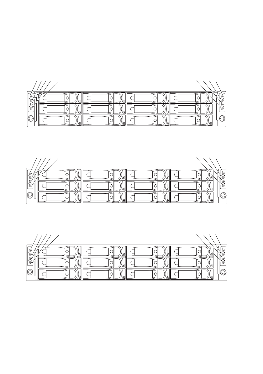
Front-Panel Features and Indicators
1-0
1-1
1-2
2-0
2-1
2-2
3-0
3-1
3-2
4-0
4-1
4-2
1234 67895
1-0
2-0
4-0
1-1
2-1
4-1
1-2
2-2
4-2
1-3
2-3
4-3
1234 5
6789
2-0
2-1
2-2
2-3
2-4
2-5
4-0
4-1
4-2
4-3
4-4
4-5
1234 5
6789
Figure 1-1. Front Panel—3.5" Hard Drives With Four System Boards
Figure 1-2. Front Panel—3.5" Hard Drives With Three System Boards
Figure 1-3. Front Panel—3.5" Hard Drives With Two System Boards
12 About Your System
Page 13
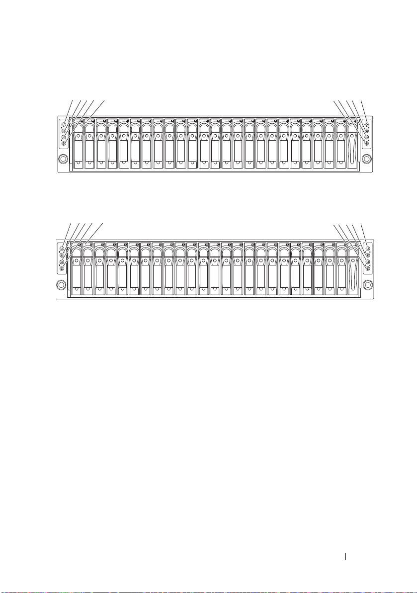
Figure 1-4. Front Panel—2.5" Hard Drives With Four System Boards
1-0
1-1
1-2
1-3
1-4
1-5
2-0
2-1
2-2
2-3
2-4
2-5
3-0
3-1
3-2
3-3
3-4
3-5
4-0
4-1
4-2
4-3
4-4
4-5
1 234 5 6789
*
1-0
1-1
1-2
1-3
1-4
1-5
1-6
1-7
2-0
2-1
2-2
2-3
2-4
2-5
2-6
2-7
4-0
4-1
4-2
4-3
4-4
4-5
4-6
4-7
1345
2
79
*
8
6
Figure 1-5. Front Panel—2.5" Hard Drives With Three System Boards
About Your System 13
Page 14
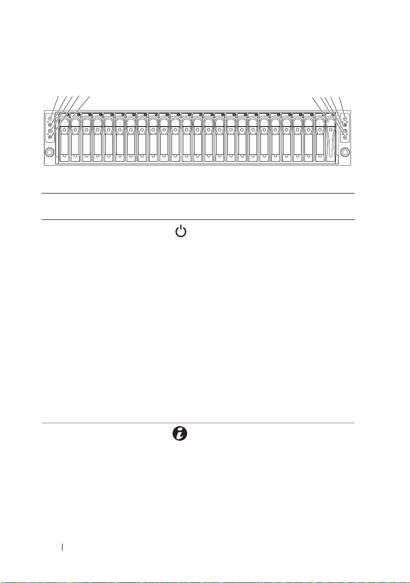
Figure 1-6. Front Panel—2.5" Hard Drives With Two System Boards
2-0
2-1
2-2
2-3
2-4
2-5
2-6
2-7
2-8
2-9
2-10
2-11
4-0
4-1
4-2
4-3
4-4
4-5
4-6
4-7
4-8
4-9
4-10
4-11
1345
2
79
*
8
6
Item Indicator, Button,
or Connector
1, 3, 7, 9 Power-on indicator/
power button (system
boards 1, 2, 4, 3)
2, 4, 6, 8 System identification
indicator/button
(system boards 1, 2,
4, 3)
Icon Description
The power-on indicator lights
when the system power is on.
The power button controls the
DC power supply output to the system.
NOTE: When powering on the system,
the video monitor can take from several
seconds to over 2 minutes to display an
image, depending on the amount of
memory installed in the system.
NOTE: On ACPI-compliant operating
systems, turning off the system using the
power button causes the system to
perform a graceful shutdown before
power to the system is turned off.
NOTE: To force an ungraceful shutdown,
press and hold the power button for
5 seconds.
The identification button can be used
to locate a particular system and system
board within a chassis.
When the button is pushed, the blue
system status indicator on the front
and the back blink until the button is
pushed again.
14 About Your System
Page 15
Item Indicator, Button,
1
2
or Connector
5 Hard drives Up to twelve hot-swappable
* Drive cover Applicable only for 2.5" hard
Icon Description
3.5-inch hard drives.
Up to twenty four hot-swappable
2.5-inch hard drives.
drive system.
Hard-Drive Indicator Patterns
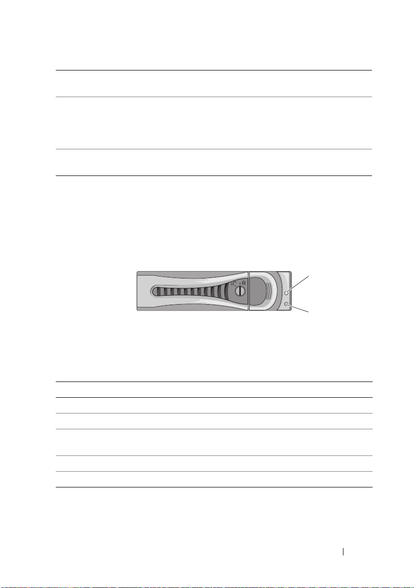
Figure 1-7. Hard Drive Indicators
1 hard-drive activity indicator
(green)
Table 1-1. Hard Drive Status Indicators
Drive-Status Indicator Pattern Condition
Off Slot empty
Solid green Hard drive online/access
Blinks green Hard drive rebuilding/ hard drive
Blinks green/amber Rebuild abort
Blinks amber Hard drive failed
2 hard-drive status indicator
(green and amber)
identification/preparing for removal
About Your System 15
Page 16
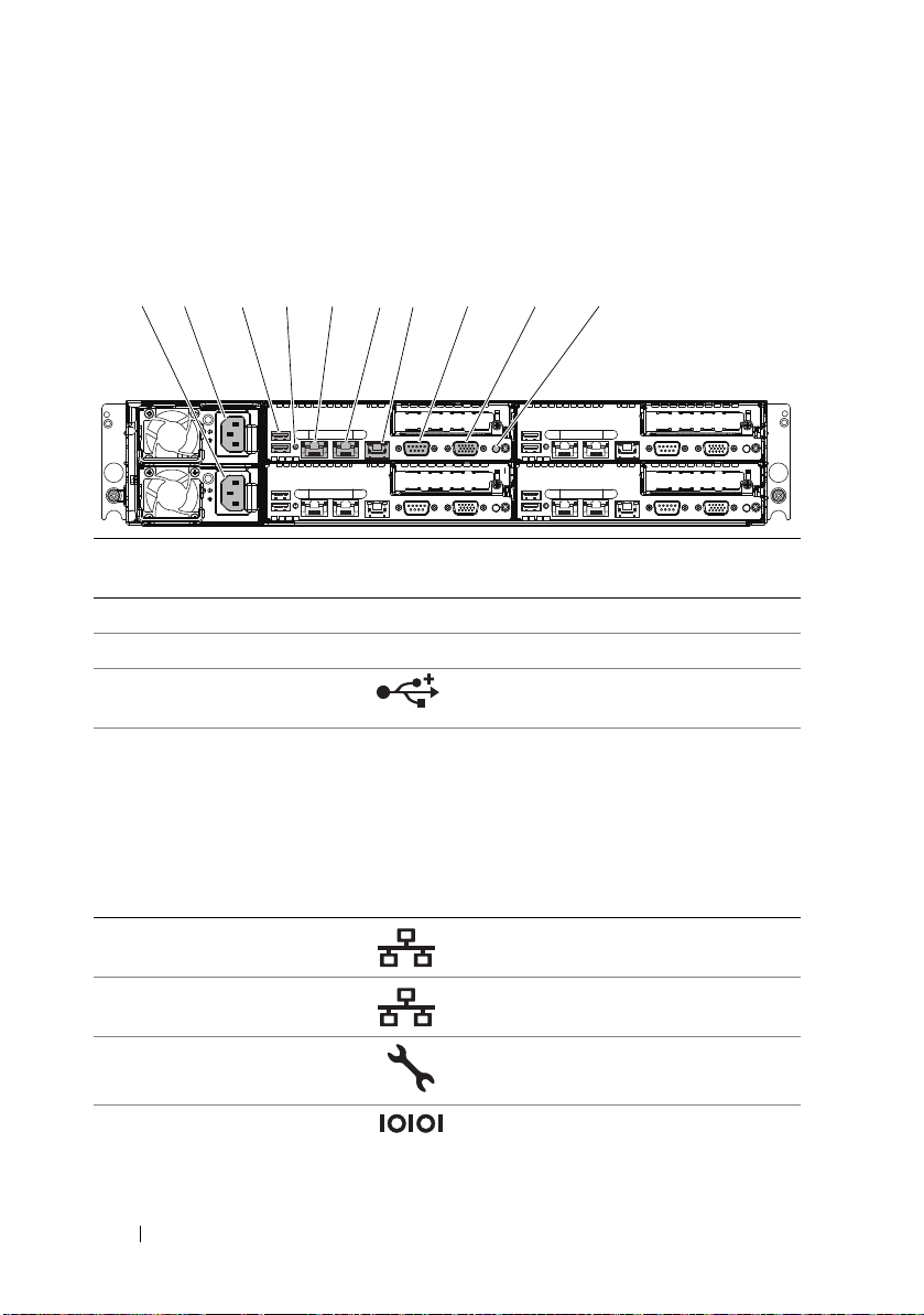
Back-Panel Features and Indicators
1 2 3 4 5 6 7 8 9 10
Figure 1-8. Back Panel—Four System Boards
Item Indicator, Button,
or Connector
1 Power supply 2 (PS2) 470W / 750W / 1100W/ 1400W
2 Power supply 1 (PS1) 470W / 750W / 1100W/ 1400W
3 USB connectors (2) Connect USB devices to the system.
4 System identification
indicator
5 Ethernet connector 1 Embedded 10/100/1000 NIC
6 Ethernet connector 2 Embedded 10/100/1000 NIC
7 KVM over IP Port Dedicated management port.
8 Serial connector Connects a serial device to the system.
Icon Description
The ports are USB 2.0-compliant.
Both the systems management software
and the identification buttons located
on the front can cause the indicator to
flash blue to identify a particular
system and system board.
Lights amber when the system needs
attention due to a problem.
connectors.
connectors.
16 About Your System
Page 17
Item Indicator, Button,
3
4
1
2
4
1
2
Icon Description
or Connector
9 Video connector Connects a VGA display to the system.
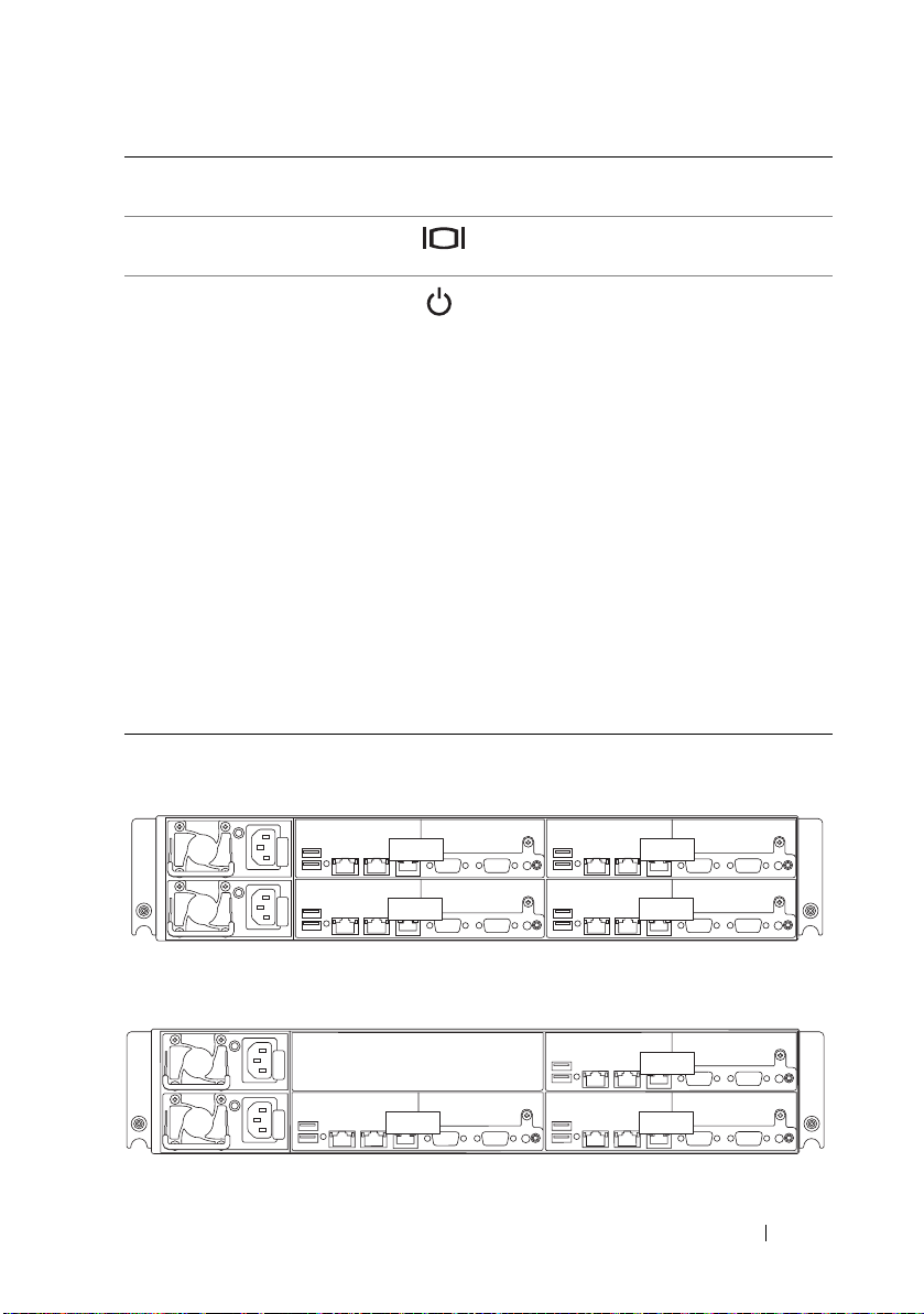
10 Power-on indicator/
power button (system
board 1)
Figure 1-9. Enumeration—Four System Boards
The power-on indicator lights
when the system power is on.
The power button controls the
DC power supply output to the system.
NOTE: When powering on the system,
the video monitor can take from several
seconds to over 2 minutes to display an
image, depending on the amount of
memory installed in the system.
NOTE: On ACPI-compliant operating
systems, turning off the system using the
power button causes the system to
perform a graceful shutdown before
power to the system is turned off.
NOTE: To force an ungraceful shutdown,
press and hold the power button for
five seconds.
Figure 1-10. Enumeration—Three System Boards
About Your System 17
Page 18
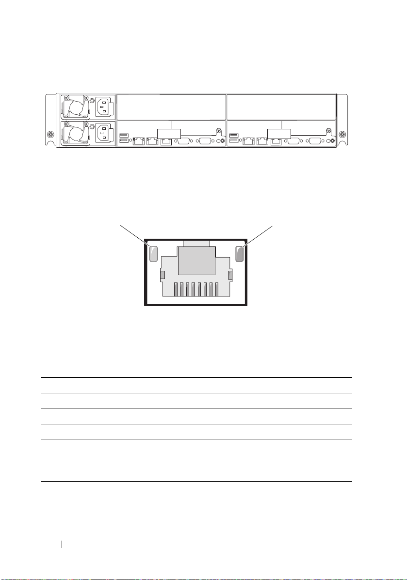
Figure 1-11. Enumeration—Two System Boards
4 2
1
2
NIC Indicator Codes
Figure 1-12. NIC Indicators
1 link indicator 2 activity indicator
NIC Status Indicator (link) Condition
Steady amber Link at 1 Gbps speed
Blinks amber Identifying port with 1 Gbps connection
Steady green Link at 100 Mbps speed
Blinks green Identifying port with 10 Mbps or 100 Mbps
connection
Off Link at 10 Mbps speed
18 About Your System
Page 19
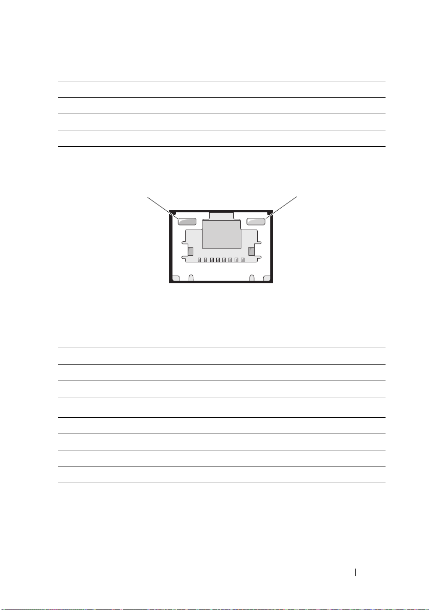
NIC Status Indicator (activity) Condition
1
2
Steady green Link LAN / No access
Blinks green Accessing LAN
Off Idle
Figure 1-13. NIC Indicators (KVM Over IP Port)
1 link indicator 2 activity indicator
NIC Status Indicator (link) Condition
Steady Green Link at 100 Mbps speed
Off Link at 10 Mbps speed
NIC Status Indicator (activity) Condition
Steady green Link LAN / No access
Blinks green LAN access
Green off Idle
About Your System 19
Page 20

Power and System Board Indicator Codes
The LEDs on the system front panel and back panel display status codes
during system startup. For location of the LEDs on the front panel,
see Figure 1-1 for 3.5" hard drive and Figure 1-4 for 2.5" hard drive systems.
For location of the LEDs on the back panel, see Figure 1-8.
Table 1-2 lists the status associated with the status codes.
Table 1-2. Status Indicator Codes
Component Indicator Condition
Power-on
indicator
System
identification
indicator
Steady Green
Blinks Amber
Blinks
Green/Amber
Steady Blue
Blinks Blue
Off
Power On S0/S1
BMC Critical condition event in Power Off
mode S4/S5
BMC Critical condition event in Power On
mode S0/S1
IPMI Via Chassis Identify Command On or
ID Button Press ID On
Only IPMI using Chassis Identify Command
Blink On
IPMI using Chassis Identify Command Off
or ID Button Press ID Off
20 About Your System
Page 21
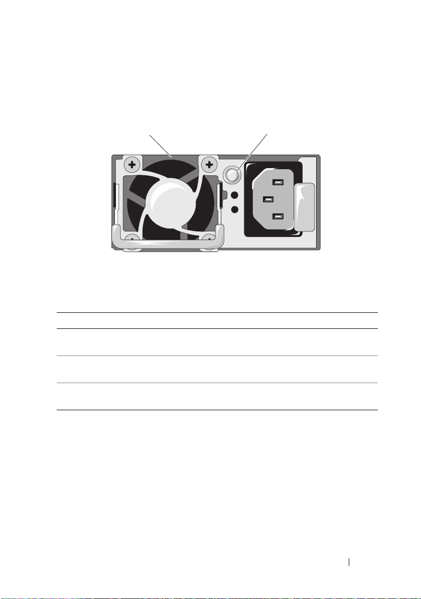
Power Supply Indicator Codes
1
2
Figure 1-14. Power Supply Status Indicator
1 power supply 2 power supply indicator
Power Supply Status Indicator Condition
Steady green Power supply is on (AC OK/DC OK) or in
standby mode (90 VAC–264 VAC)
Steady yellow Power supply faulty
(UVP/OVP/OCP/SCP/OTP/Fan Fault)
Yellow off Power supply is off or AC input voltage is out of
normal operating range (90 VAC–264 VAC)
About Your System 21
Page 22
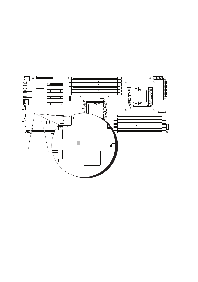
BMC Heart Beat LED
2
1
The system board provides BMC heart beat LED (CR24) for BMC debugs.
When BMC firmware is ready, the BMC heart beat LED blinks.
Figure 1-15. BMC Heart Beat LED
1 BMC heart beat LED 2 system board
22 About Your System
Page 23

POST Error Codes
Collecting System Event Log for Investigation
Error Messages are logged in the System Event Log (SEL). The SEL can be
accessed through system BIOS and the BMC setup for investigation. You can
also access SEL by browsing to the IP address of the BMC.
Code Log in BMC Cause Corrective Actions
0000h Yes Timer Count Read/Write Error Remove AC power to the
system for 10 seconds and
restart the system.
If the problem persists, see
"Getting Help" on page 143.
0003h Yes CMOS Battery Error See "Troubleshooting the
System Battery" on
page 118.
0004h Yes CMOS Diagnostic Status Error Remove AC power to the
system for 10 seconds and
restart the system.
If the problem persists, see
"Getting Help" on page 143.
0005h Yes CMOS Checksum Error Remove AC power to the
system for 10 seconds and
restart the system.
If the problem persists, see
"Getting Help" on page 143.
000Bh Yes CMOS Memory Size Error Remove AC power to the
system for 10 seconds and
restart the system.
If the problem persists, see
"Getting Help" on page 143.
About Your System 23
Page 24

Code Log in BMC Cause Corrective Actions
000Ch Yes RAM Read/Write Test Error Remove AC power to the
system for 10 seconds and
restart the system.
If the problem persists, see
"Getting Help" on page 143.
0012h Yes CMOS Date Time Error See "Troubleshooting the
System Battery" on
page 118.
If the problem persists, see
"Getting Help" on page 143.
0040h Yes Refresh Timer Error Remove AC power to the
system for 10 seconds and
restart the system.
If the problem persists, see
"Getting Help" on page 143.
0041h Yes Display Memory Error Remove AC power to the
system for 10 seconds and
restart the system.
If the problem persists, see
"Getting Help" on page 143.
0044h Yes DMAC Controller Error See "Troubleshooting
System Memory" on
page 121.
If the problem persists, see
"Getting Help" on page 143.
0045h Yes DMAC1 Channel Register Error See "Troubleshooting
System Memory" on
page 121.
If the problem persists, see
"Getting Help" on page 143.
0046h Yes DMAC2 Channel Register Error See "Troubleshooting
System Memory" on
page 121.
If the problem persists, see
"Getting Help" on page 143.
24 About Your System
Page 25

Code Log in BMC Cause Corrective Actions
0047h Yes PMM Memory Allocation Error See "Troubleshooting
System Memory" on
page 121.
If the problem persists, see
"Getting Help" on page 143.
0048h Yes Password Check Error Reset password.
See "Jumper Settings" on
page 139.
If the problem persists, see
"Getting Help" on page 143.
004Ah Yes ADM Module Error See "Getting Help" on
page 143.
004Bh Yes Language Module Error See "Getting Help" on
page 143.
005Dh Yes ATA SMART Feature Error See "Getting Help" on
page 143.
005Eh Yes Non-Critical Password Check
Error
0060h Yes HDD 0 Error See "Troubleshooting a
0061h Yes HDD 1 Error See "Troubleshooting a
0062h Yes HDD 2 Error See "Troubleshooting a
0063h Yes HDD 3 Error See "Troubleshooting a
0064h Yes HDD 4 Error See "Troubleshooting a
0065h Yes HDD 5 Error See "Troubleshooting a
Reset password. See
"Jumper Settings" on
page 139.
If the problem persists, see
"Getting Help" on page 143.
Hard Drive" on page 123.
Hard Drive" on page 123.
Hard Drive" on page 123.
Hard Drive" on page 123.
Hard Drive" on page 123.
Hard Drive" on page 123.
About Your System 25
Page 26

Code Log in BMC Cause Corrective Actions
0066h Yes HDD 6 Error See "Troubleshooting a
Hard Drive" on page 123.
0067h Yes HDD 7 Error See "Troubleshooting a
Hard Drive" on page 123.
0080h Yes ATAPI 0 Error
0081h Yes ATAPI 1 Error Remove AC power to the
system for 10 seconds and
restart the system.
If the problem persists, see
"Getting Help" on page 143.
0082h Yes ATAPI 2 Error Remove AC power to the
system for 10 seconds and
restart the system.
If the problem persists, see
"Getting Help" on page 143.
0083h Yes ATAPI 3 Error Remove AC power to the
system for 10 seconds and
restart the system.
If the problem persists, see
"Getting Help" on page 143.
0084h Yes ATAPI 4 Error Remove AC power to the
system for 10 seconds and
restart the system.
If the problem persists, see
"Getting Help" on page 143.
0085h Yes ATAPI 5 Error Remove AC power to the
system for 10 seconds and
restart the system.
If the problem persists, see
"Getting Help" on page 143.
26 About Your System
Page 27

Code Log in BMC Cause Corrective Actions
0086h Yes ATAPI 6 Error Remove AC power to the
system for 10 seconds and
restart the system.
If the problem persists, see
"Getting Help" on page 143.
0087h Yes ATAPI 7 Error Remove AC power to the
system for 10 seconds and
restart the system.
If the problem persists, see
"Getting Help" on page 143.
0120h Yes CPU1 Thermal Failure due to
PROCHOT#
0121h Yes CPU2 Thermal Failure due to
PROCHOT#
0122h Yes CPU3 Thermal Failure due to
PROCHOT#
Ensure that the processor
heat sinks are properly
installed.
See "Troubleshooting
Processors" on page 126 and
"Troubleshooting System
Cooling Problems" on
page 120.
Ensure that the processor
heat sinks are properly
installed.
See "Troubleshooting
Processors" on page 126 and
"Troubleshooting System
Cooling Problems" on
page 120.
Ensure that the processor
heat sinks are properly
installed.
See "Troubleshooting
Processors" on page 126 and
"Troubleshooting System
Cooling Problems" on
page 120.
About Your System 27
Page 28

Code Log in BMC Cause Corrective Actions
0123h Yes CPU4 Thermal Failure due to
PROCHOT#
0150h Yes Processor failed BIST Remove AC power to the
0151h Yes Processor failed BIST Remove AC power to the
0152h Yes Processor failed BIST Remove AC power to the
0153h Yes Processor failed BIST Remove AC power to the
0160h Yes CPU1 Processor missing
microcode
0161h Yes CPU2 Processor missing
microcode
Ensure that the processor
heat sinks are properly
installed.
See "Troubleshooting
Processors" on page 126 and
"Troubleshooting System
Cooling Problems" on
page 120.
system for 10 seconds and
restart the system.
If the problem persists, see
"Getting Help" on page 143.
system for 10 seconds and
restart the system.
If the problem persists, see
"Getting Help" on page 143.
system for 10 seconds and
restart the system.
If the problem persists, see
"Getting Help" on page 143.
system for 10 seconds and
restart the system.
If the problem persists, see
"Getting Help" on page 143.
A BIOS update is required.
If the problem persists, see
"Getting Help" on page 143.
A BIOS update is required.
If the problem persists, see
"Getting Help" on page 143.
28 About Your System
Page 29

Code Log in BMC Cause Corrective Actions
0162h Yes CPU3 Processor missing
microcode
0163h Yes CPU4 Processor missing
microcode
0180 Yes CPU 1 stepping no support Ensure that your processors
0181 Yes CPU 2 stepping no support Ensure that your processors
0182 Yes CPU 3 stepping no support Ensure that your processors
0183 Yes CPU 4 stepping no support Ensure that your processors
A BIOS update is required.
If the problem persists, see
"Getting Help" on page 143.
A BIOS update is required.
If the problem persists, see
"Getting Help" on page 143.
match and conform to the
type described in the
processor technical
specifications outlined in
your system’s Getting
Started Guide.
match and conform to the
type described in the
processor technical
specifications outlined in
your system’s Getting
Started Guide.
match and conform to the
type described in the
processor technical
specifications outlined in
your system’s Getting
Started Guide.
match and conform to the
type described in the
processor technical
specifications outlined in
your system’s Getting
Started Guide.
About Your System 29
Page 30

Code Log in BMC Cause Corrective Actions
0192h Yes L2 cache size mismatch Remove AC power to the
system for 10 seconds and
restart the system.
If the problem persists, see
"Getting Help" on page 143.
0193h Yes CPUID, Processor stepping are
different
0194h Yes CPUID, Processor stepping are
different
0195h Yes Front side bus mismatch Ensure that your processors
0196h Yes CPUID, Processor Model are
different
Ensure that your processors
match and conform to the
type described in the
processor technical
specifications outlined in
your system’s Getting
Started Guide.
Ensure that your processors
match and conform to the
type described in the
processor technical
specifications outlined in
your system’s Getting
Started Guide.
match and conform to the
type described in the
processor technical
specifications outlined in
your system’s Getting
Started Guide.
Ensure that your processors
match and conform to the
type described in the
processor technical
specifications outlined in
your system’s Getting
Started Guide.
30 About Your System
Page 31

Code Log in BMC Cause Corrective Actions
0197h Yes Processor speeds mismatched Ensure that your processors
match and conform to the
type described in the
processor technical
specifications outlined in
your system’s Getting
Started Guide.
0198h Yes QPI mismatched Check the SEL to identify
and resolve the problem.
If the problem persists, see
"Getting Help" on page 143.
8101h No USB HC Not Found See "Troubleshooting a
USB Device" on page 114.
If the problem persists, see
"Getting Help" on page 143.
8102h No USB Device Init Error See "Troubleshooting a
USB Device" on page 114.
If the problem persists, see
"Getting Help" on page 143.
8103h No USB Device Disabled To enable USB device, see
"USB Configuration" on
page 43.
See "Troubleshooting a
USB Device" on page 114.
If the problem persists, see
"Getting Help" on page 143.
8104h No USB OHCI EMUL Not
Supported
8105h Yes USB EHCI 64bit Data Structure
Error
See "Troubleshooting a
USB Device" on page 114.
If the problem persists, see
"Getting Help" on page 143.
See "Troubleshooting a
USB Device" on page 114.
If the problem persists, see
"Getting Help" on page 143.
About Your System 31
Page 32

Code Log in BMC Cause Corrective Actions
8301h No SMBIOS Not Enough Space In
F000
8302h No SMBIOS Not Enough Space In
F000
8400h Yes Redirect Memory Error See "Troubleshooting
F001h No System Event Log Full Check the SEL for details
F002h No BMC FRU Header checksum
bad
F003h No BIOS Update BMC FRU failed Remove AC power to the
F004h No BMC FRU Internal Area
checksum bad
See "Troubleshooting
System Memory" on
page 121.
If the problem persists, see
"Getting Help" on page 143.
See "Troubleshooting
System Memory" on
page 121.
If the problem persists, see
"Getting Help" on page 143.
System Memory" on
page 121.
If the problem persists, see
"Getting Help" on page 143.
on the events, then clear
the SEL.
Remove AC power to the
system for 10 seconds and
restart the system.
If the problem persists, see
"Getting Help" on page 143.
system for 10 seconds and
restart the system.
If the problem persists, see
"Getting Help" on page 143.
Remove AC power to the
system for 10 seconds and
restart the system.
If the problem persists, see
"Getting Help" on page 143.
32 About Your System
Page 33

Code Log in BMC Cause Corrective Actions
F005h No BIOS Update FRU Internal Area
checksum failed
FFFFh No Undefined BIOS Error Remove AC power to the
Remove AC power to the
system for 10 seconds and
restart the system.
If the problem persists, see
"Getting Help" on page 143.
system for 10 seconds and
restart the system.
If the problem persists, see
"Getting Help" on page 143.
Other Information You May Need
WARNING: See the safety and regulatory information that shipped with your
system. Warranty information may be included within this document or as a
separate document.
The Getting Started Guide provides an overview of rack installation,
system features, setting up your system, and technical specifications.
NOTE: Always check for updates on support.dell.com/manuals and read the
updates first because they often supersede information in other documents.
About Your System 33
Page 34

34 About Your System
Page 35

Using the System Setup Program
Start Menu
The system employs the latest AMI CMOS BIOS, which is stored in Flash
memory. The Flash memory supports the Plug and Play specification,
and contains a System Setup program, the Power On Self Test (POST)
routine, and the PCI auto-configuration utility.
This system board supports system BIOS shadowing, enabling the BIOS to
execute from 64-bit onboard write-protected DRAM.
This Setup utility should be executed under the following conditions:
• When changing the system configuration,
– Hard drives, diskette drives, and peripherals
– Password protection from unauthorized use
– Power management features
• When a configuration error is detected by the system and you are
prompted to make changes to the Setup utility
• When redefining the communication ports to prevent any conflicts
• When changing the password or making other changes to the security
setup
NOTE: Only items in brackets [ ] can be modified. Items that are not in brackets are
display only.
configure items such as:
Using the System Setup Program 35
Page 36

System Setup Options at Boot
You can initiate Setup by pressing <F2> during POST.
Console Redirection
The console redirection allows a remote user to diagnose and fix problems
on a system, which has not successfully booted the operating system.
The centerpiece of the console redirection is the BIOS Console. The BIOS
Console is a Flash ROM-resident utility that redirects input and output over
a serial or modem connection.
The BIOS supports console redirection to a serial port. If serial port based
headless system support is provided by the system, the system must provide
support for redirection of all BIOS driven console I/O to the serial port.
The driver for the serial console must be capable of supporting the
functionality documented in the ANSI Terminal Definition.
36 Using the System Setup Program
Page 37

Main Menu
Use [ENTER],[TAB]
or [SHIFT-TAB] to
select a field
Use [+] or [-] to
configure system Time.
Select Screen
Select Item
+–
Ta b
F1
F10 Save and Exit
ESC
Change Field
Select Field
General Help
Exit
The main menu displays information about your system boards and BIOS.
Main Screen
Figure 2-1. Main System Setup Program Screen
NOTE: The options for the System Setup program change based on the system
configuration.
NOTE: The System Setup program defaults are listed under their respective options
in the following sections, where applicable.
Using the System Setup Program 37
Page 38

AMIBIOS Settings
Option Description
Version Displays the BIOS version. Check this version number when
updating BIOS from the manufacturer.
Build Date Displays the date the BIOS was created.
ID Displays the BIOS ID.
Processor Settings
Option Description
Type Displays the type of processor installed on the system board.
Speed Displays the maximum speed of the processor.
Count Displays the number of installed processors.
System Memory Settings
Option Description
Size Displays how much memory (DRAM) is installed on the system
board.
System Time Scroll to this item to adjust the time.
System Date Scroll to this item to adjust the date.
38 Using the System Setup Program
Page 39

Advanced Menu
This option displays a table of items that defines advanced information about
your system.
CAUTION: Making incorrect settings to items on these pages may cause the
system to malfunction. Unless you have experience adjusting these items, we
recommend that you leave these settings at the default values. If making settings
to items on these pages causes your system to malfunction or prevents the system
from booting, open BIOS and choose Load Optimal Defaults in the Exit menu to
boot up normally.
CPU Configuration
Option Description
Virtualization Technology
(VT) (Disabled default)
Execute-Disable Bit
Capability (Enabled default)
C1E Support
(Enabled default)
Hardware Prefetcher
(Enabled default)
Adjacent Cache Line Prefetch
(Disabled default)
Hyper-Threading Technology
(HT) (Enabled default)
Intel(R) TurboMode tech
(Disabled default)
Enable this option when the processor supports VT.
A full reset is needed to change its state.
Forces the XD feature flag to always return 0.
Enable this option to enable or disable the Enhanced
Halt State.
For UP Platforms, leave it enabled. For DP/MP
servers, it may used to tune performance to the
specific application.
Enable this option to enable or disable the Adjacent
Cache Line Prefetch Disable Feature.
When Disabled only one thread per enabled core
is enabled.
Turbo mode allows processor cores to run faster than
marked frequency in specific condition.
Using the System Setup Program 39
Page 40

Option Description
Active Processor Cores
(All default)
Frequency Ratio Sets the processor ratio between Min. and Max.
Intel(R) C-STATE tech
(Enabled default)
C6 State (Enabled default) C6 Support. When CPU is in idle mode.
Number of cores to enable in each processor package.
Use [+] or [-] to configure the value.
CState: CPU idle is set to C2/C3/C4.
Memory Configuration
Option Description
Memory Frequency (Auto
default)
Memory Mode
(Independent default)
NUMA Support
(Enabled default)
Forces a DDR3 frequency slower than the common
tck detected using SPD.
Independent: independent channel.
Enables or disables NUMA:
•
Enabled
NUMA aware operating system.
•
Disabled
non-NUMA operating system.
: efficiently executes software for
: better memory access performance for
40 Using the System Setup Program
Page 41

IDE Configuration
NOTE: The AHCI Port is shown in SETUP screen when it is in the Enhanced AHCI or
RAID mode.
Option Description
Configure SATA as Configures the SATA:
•IDE
Hard Disk Write Protect
(Disabled default)
IDE Detect Time Out (Sec)
(35 default)
– SATA#1 Configuration (
Configures SATA#1.
– SATA#2 Configuration (
Configures SATA#2.
• Primary Master/Slave is SATA Port 0/2
• Secondary Master/Slave is SATA Port 1/3
•AHCI/RAID
• AHCI Port 0~5
Enables or disables device write protection. This is
effective only if the device is accessed through BIOS.
Selects the time out value for detecting
ATA/ATAPI device(s).
Enhanced
Enhanced
default)
default)
Primary IDE Master
To configure Primary, Secondary, Third or Fourth device on the IDE channel.
Option Description
Device Displays the type of device assigned to this channel.
Vendor Displays the manufacturer's name of the device.
Size Displays the size of the device (GB).
LAB Mode: Indicates whether LAB access mode is supported or
not supported.
Block (Multi-Sector
Transfer) (Auto default)
PIO Mode (Auto default) Indicates whether PIO mode is supported.
Indicates whether multi-sector transfer is supported.
Using the System Setup Program 41
Page 42

Option Description
Async DMA Indicates whether Async DMA is supported.
Ultra DMA Indicates whether Ultra DMA is supported.
S.M.A.R.T. Indicates whether S.M.A.R.T. mode is supported.
Ty p e ( Auto default) Selects which type of device is installed or select
Auto to enable the system to automatically configure
the device:
• Not Installed
•
Auto
: Auto detected
CD/DVD
•
ARMD
•
LAB/LARGE Mode (Auto
default)
Block (Multi-Sector Transfer)
(Auto default)
PIO Mode (Auto default) Selects the device PIO (Programmed Input/Output)
Enables LAB access mode:
•
Disabled
•
Auto
it and the device is not already formatted with
LAB mode disabled.
Enables multi-sector transfer block mode:
•
Disabled
occurs one sector at a time
•
Auto
multiple sectors at a time if supported by the device
mode, which determines the data transfer mode used
by IDE drives. PIO mode uses the processor's
registers for data transfer:
•
Auto
default PIO mode
0 ~ 4
•
: ATAPI CD/DVD detected
: ATAPI removable media device detected
: LAB access mode is disabled.
: Enables LAB Mode if the device supports
: data transfer from and to the device
: data transfer from and to the device occurs
: automatically detects optimal or
: select PIO mode 0 to 4
42 Using the System Setup Program
Page 43

Option Description
DMA Mode (Auto default) Selects the devices DMA (Direct Memory Access)
mode, which transfers data from channel to channel
without using the processor, resulting in faster data
transfer then when the processor is used for every
byte of transfer:
•
Auto
: automatically detects optimal or default
DMA mode
SWDMA0 ~ SWDMA2
•
DMA 0 to 2
•
MWDMA0 ~ MWDMA2
DMA 0 to 2
UDMA 0 ~ UDMA5
•
S.M.A.R.T. (Auto default) Self Monitoring Analysis and Reporting Technology)
reports drive degradation to the operating system to
warn you of potential failure:
•
Auto
: automatically sets optimal or default
S.M.A.R.T. mode
32Bit Data Transfer
(Enabled default)
Disabled
•
•
Enabled
Enables or disables 32-bit data transfer.
: disables S.M.A.R.T.
: enables S.M.A.R.T.
: selects SingleWord
: selects MultiWord
: selects Ultra DMA 0 to 5
USB Configuration
NOTE: The USB Mass Storage Device Configuration is shown in SETUP
screen when USB Mass Storage is plugged. If USB device (Floppy, CDROM) is used
to install RedHat
work around it, because RedHat Linux 9.0 is not supported completely for
hand-off function.
Option Description
USB Devices Enabled Displays USB devices currently detected.
Legacy USB Support
(Enabled default)
®
Linux 9.0, change USB 2.0 Controller Mode to FullSpeed to
Enables support for legacy USB devices. Auto option
disables legacy support if no USB devices are
connected.
Using the System Setup Program 43
Page 44

Option Description
USB 2.0 Controller Mode
(HiSpeed default)
BIOS EHCI Hand-Off
(Enabled default)
USB Mass Storage Reset
Delay (20 sec default)
Device# USB device model name
Emulation Type
(Auto default)
Configures the USB 2.0 controller in HiSpeed
(480 Mbps) or FullSpeed (12 Mbps).
This is a work around for operating systems without
EHCI handoff support. The EHCI ownership change
should be claimed by EHCI driver.
The number of seconds that the POST waits for the
USB mass storage device after the start Unit
command is issued.
If Auto, USB devices, which are less than 530 MB are
emulated as floppy and others are be emulated as
hard disk. Forced FDD option can be used to force a
formatted hard drive to boot as FDD (e.g. ZIP drive)
PCI Configuration
Option Description
NIC Function Support (PXE
default)
NIC1 Option ROM (Enable
default)
NIC2 Option ROM (Enable
default)
NIC Function Disable or PXE/iSCSI Support
Set OnBoard 82576EB Disable/Enable Option ROM
Set OnBoard 82576EB Disable/Enable Option ROM
44 Using the System Setup Program
Page 45

Boot Menu
Option Description
Boot Settings Configuration Configures the settings during system boot.
Boot Device Priority Specifies the boot device priority.
Hard Disk Drives Specifies the boot device priority sequence from the
available hard drives.
Removable Drives Specifies the boot device priority sequence from the
available removable drives.
CD/DVD Drives: Specifies the boot device priority sequence from the
available CD/DVD drives.
Boot Settings Configuration
Option Description
Quick Boot
(Enabled default)
Quiet Boot
(Disabled default)
Wait For 'F1' If Error
(Disabled default)
Allows BIOS to skip certain tests during the POST,
which decreases boot up time.
Enables or disables this item:
•
Disabled
Enabled
•
POST messages.
Waits for F1 key to be pressed if error occurs.
: displays normal POST messages.
: displays OEM logo instead of
Security Menu
Option Description
Supervisor Password Displays whether the supervisor password is installed
or not.
User Password Displays whether the user password is installed
or not.
Using the System Setup Program 45
Page 46

Option Description
Change Supervisor Password Installs, changes or clears the password.
If you select these items and press Enter, a dialog box
appears and then you can enter a password. You can
enter no more than six letters or numbers.
Press Enter after you have typed in the password.
A second dialog box asks you to retype the password
for confirmation. Press Enter after you have retyped
it correctly. The password is required at boot time,
or when the user enters the Setup Utility.
User Access Level
(Full Access default)
Change User Password Installs, changes or clears the password.
Password Check
(Setup default)
Boot Sector Virus Protection
(Disabled default)
Sets the user access level:
•
No Access
•
View Only
but the fields cannot be changed.
Limited
•
such as date and time.
•
Full Access
and the fields can be changed.
Selects the password check mode:
Setup: checks password while invoking setup.
Always: checks password while invoking setup as well
as on each boot.
Enables and disables boot sector virus protection
: prevents user access to the Setup Utility.
: allows user access to the Setup Utility
: allows only limited fields to be changed
: allows user access to the Setup Utility
46 Using the System Setup Program
Page 47

Server Menu
NOTE: Delay time, Minimum time, and Maximum time are only shown in SETUP
screen when AC Power Recovery Delay is set to User define. The selection of
Restore on AC Power Loss setup to Power-on or Last State takes 60 seconds for
running BMC initialization after AC Power on.
Option Description
Power Management (Node
Management default)
IOAT2 (Disabled default) Enables or disables IOAT2.
Wake on RING function
(Disabled default)
WHEA Support
(Disabled default)
Restore on AC Power Loss
(Power On default)
AC Power Recovery Delay
(Immediate default)
Sets power mode. The options are:
• Maximum Performance
• Operating system Control/EIST
• Active Power Controller
• Node Management
If Maximum Performance or Active Power Controller is
selected, Intel SpeedStep is disabled. If OS
Control/EIST or Node Management is selected,
Intel SpeedStep is enabled. ME function is disabled
if OS Control/EIST is selected.
Enables or disables Wake on RING function.
Enables or disables Windows Hardware Error
Architecture.
Restores the AC power setting. The options are
Power Off, Power On and Last State.
Selects the time of system power on after BMC initiates:.
•
Immediate
Random
•
User define
•
Delay Time: Sets AC power recovery delay time
–
between minimum and maximum.
: powers on directly after BMC initiates.
: randomly selects time to power on.
: user selects the time.
Using the System Setup Program 47
Page 48

System Management
Option Description
Server Board Part Number Displays server board part number.
Server Board Serial Number Displays server board serial number.
NIC 1 MAC Address Displays NIC1 MAC Address.
NIC 2 MAC Address Displays NIC2 MAC Address.
System Part Number Displays system part number.
System Serial Number Displays system serial number.
Chassis Part Number Displays chassis part number.
Chassis Serial Numbers Displays chassis serial numbers.
BIOS Version Displays current BIOS version.
BMC Device ID Displays BMC device ID.
BMC Firmware Revision Displays BMC firmware version.
FCB Firmware Revision Displays FCB firmware version.
Remote Access Configuration
Option Description
Remote Access
(Enabled default)
Serial Port Number
(COM1 default)
Serial Port Mode
(115200 8,n,1 default)
Flow Control (None default) Selects flow control for console redirection. This item
Selects remote access type.
Selects serial port for console redirection. Make sure
the selected port is enabled. This item disappears
when Remote Access is disabled.
Selects serial port settings. This item disappears
when Remote Access is disabled.
disappears when Remote Access is disabled.
48 Using the System Setup Program
Page 49

Option Description
Redirection After BIOS POST
(Always default)
Terminal Type
(VT100 default)
VT-UTF8 Combo Key
Support (Enabled default)
Terminal Display Mode
(Normal mode default)
NOTE: When Flow Control is set to Software, the Hyper Terminal on remote side is
discontinued by pressing <Ctrl><S>. But the <Ctrl><S> is also the Setup Key Stroke
for setting onboard NIC PXE Option ROM Configuration. Therefore, we suggest
users change <Ctrl><S> to <Ctrl><B> in PXE OPROM Configuration in order to avoid
that the Hyper Terminal on remote side is discontinued when pressing <Ctrl><S>.
Selects the settings for the redirection. This item
disappears when Remote Access is disabled:
•
Disabled
Boot Loader
•
boot loader.
•
Always
operating systems may not work if set to
Selects the target terminal type. This item disappears
when Remote Access is disabled.
Enables or disables VT-UTF8 combination key
support for ANSI/VT100 terminals. This item
disappears when Remote Access is disabled.
Selects Terminal Display Mode.
Options:
• Normal Mode
• Recorder Mode
: turns off the redirection after POST.
: redirection is active during POST and
: redirection is always active. (Some
Always
)
IPMI Configuration
Option Description
Status Of BMC Displays BMC status.
BMC Firmware Revision Displays BMC Firmware Revision.
View BMC System
Event Log
Selecting this option and pressing Enter, displays:
Total Number Of Entries, SEL Entry Number,
SEL Record ID, SEL Record Type,
Event Time Stamp, Generator ID, Event Message
Format Version, Event Sensor Type, Event Sensor
Number, Event Dir Type, and Event Data.
Using the System Setup Program 49
Page 50

Option Description
Clear BMC System Event Log Clears BMC System Event Log.
BMC PEF status Displays BMC PEF status.
Set BMC NIC
(Shared default)
Set LAN Configuration Allows LAN Configuration settings.
Sets the type of BMC NIC from BIOS. BMC is reset.
LAN Configuration
Option Description
Channel Number
(01 default)
BMC IP address source
(DHCP default)
Enters channel number for SET LAN Config
Command. Proper value is below 16.
Sets BMC IP address source from BIOS.
Power Throttling Configuration
Option Description
Power Throttling Enable or disable Power throttling
Power CAP Enable or disable Power CAP
Chassis CAP Set Chassis CAP value
NOTE: The default values are dependant on BMC setting
IP Address
Option Description
IP Address (default value
depends on BMC setting)
50 Using the System Setup Program
Enters IP address in decimal in the form of
XXX.XXX.XXX.XXX (XXX is less than 256 and in
decimal only).
NOTE: When BMC IP status is static, IP Address is
useful
Page 51

Subnet Mask
Option Description
Subnet Mask (default value
depends on BMC setting)
NOTE: When BMC IP status is static, Subnet Mask is useful.
Enters subnet mask in decimal in the form of
XXX.XXX.XXX.XXX (XXX is less than 256 and
in decimal only).
Default Gateway IP
Option Description
Default Gateway IP
(default value depends
on BMC setting)
Enters default Gateway IP in decimal in the form of
XXX.XXX.XXX.XXX (XXX is less than 256 and in
decimal only).
Exit Menu
Option Description
Save Changes
and Exit
Discard
Changes and
Exit
Discard
Changes
Select this item and press Enter to save any changes that you have
made in the Setup utility and exit the Setup utility. When the Save
Changes and Exit dialog box appears, Select [OK] to save the
changes and exit, or press N to return to the setup main menu.
Select this item and press Enter to discard any changes that you have
made in the Setup utility and exit the Setup utility. When the
Discard Changes and Exit dialog box appears, Select [OK] to discard
changes and exit, or press N to return to the setup main menu.
Select this item and press Enter to discard any changes you have
made without leaving the setup utility
Using the System Setup Program 51
Page 52

Option Description
Load Optimal
Defaults
Load Failsafe
Defaults
Select this item and press Enter, a dialog box asks if you want to
install optimal settings for all the items in the Setup utility. Select
[OK] to indicate Yes, and then press Enter to install the optimal
settings.
The optimal settings default values are quite demanding and your
system might not function properly if you are using slower memory
chips or other kinds of low-performance components.
If you select this item and press Enter, a dialog box asks if you want
to install fail-safe settings for all the items in the Setup utility. Select
[OK] to indicate Yes, and then press Enter to install the fail-safe
settings.
The fail-safe settings default values are not demanding so a system
should be able to operate with the fails safe settings even if it is
installed with slower memory chips or other kinds of lowperformance components.
52 Using the System Setup Program
Page 53

Installing System Components
Safety Instructions
WARNING: Working on systems that are still connected to a power supply can be
extremely dangerous.
CAUTION: System components and electronic circuit boards can be damaged by
discharge of static electricity.
CAUTION: Many repairs may only be done by a certified service technician.
You should only perform troubleshooting and simple repairs as authorized in
your product documentation, or as directed by the online or telephone service
and support team. Damage due to servicing that is not authorized by Dell is not
covered by your warranty. Read and follow the safety instructions that came
with the product.
To avoid injury to yourself or damage to your system, follow these guidelines:
• Always disconnect the system from the power outlet whenever you are
working inside the system.
• If possible, wear a grounded wrist strap when you are working inside the
system. Alternatively, discharge any static electricity by touching the bare
metal chassis of the system case, or the bare metal body of any other
grounded appliance.
• Hold electronic circuit boards by the edges only. Do not touch the
components on the board unless it is necessary to do so. Do not flex or
stress the circuit board.
• Leave all components inside the static-proof packaging until you are ready
to use the component for the installation.
Recommended Tools
• Phillips screwdriver
• Flat-tipped screwdriver
• Set of jewelers screwdrivers
Installing System Components 53
Page 54

Inside the System
2
1
6
3
4
5
CAUTION: Many repairs may only be done by a certified service technician.
You should only perform troubleshooting and simple repairs as authorized in
your product documentation, or as directed by the online or telephone service
and support team. Damage due to servicing that is not authorized by Dell is not
covered by your warranty. Read and follow the safety instructions that came
with the product.
CAUTION: This system must be operated with the system cover installed to
ensure proper cooling.
NOTE: The illustration in this section shows a system with 3.5-inch hard drives.
Figure 3-1. Inside the System
1 system board assembly (4) 2 power supply (2)
3 power distribution board (2) 4 cooling fan (4)
5 hard-drive bay 6 hard drive (12)
54 Installing System Components
Page 55

Hard Drives
1
The installation and removal procedures for the 3.5-inch hard drive and the
2.5-inch hard drive are similar. Following is an example showing the
replacement procedure of a 3.5-inch hard drive.
Removing a Hard-Drive Blank
CAUTION: To maintain proper system cooling, all empty hard-drive bays must
have drive blanks installed.
NOTE: This section is applicable to systems with hot-swappable hard drives only.
1 Grasp the front of the hard-drive blank, pull and slide the blank out
until it is free of the drive bay. See Figure 3-2.
Figure 3-2. Removing or Installing a Hard-Drive Blank
1 hard-drive blank
Installing a Hard-Drive Blank
Align the hard-drive blank with the drive bay and insert the blank into the
drive bay until the retention latch clicks into place. See Figure 3-2.
Installing System Components 55
Page 56

Removing a Hard-Drive Carrier
4
1
3
2
CAUTION: Many repairs may only be done by a certified service technician.
You should only perform troubleshooting and simple repairs as authorized in
your product documentation, or as directed by the online or telephone service
and support team. Damage due to servicing that is not authorized by Dell is not
covered by your warranty. Read and follow the safety instructions that came
with the product.
1
Turn the lock lever counterclockwise until it points to the unlock symbol.
2
Slide the release button to open the release handle. See Figure 3-3.
3
Using the release handle, pull the hard-drive carrier out of the
hard-drive bay.
CAUTION: To maintain proper system cooling, all empty hard-drive bays must
have drive blanks installed.
Figure 3-3. Removing and Installing a Hard-Drive Carrier
1 release button 2 lock lever
3 release handle 4 hard-drive carrier
56 Installing System Components
Page 57

Installing a Hard Drive Carrier
CAUTION: Many repairs may only be done by a certified service technician.
You should only perform troubleshooting and simple repairs as authorized in
your product documentation, or as directed by the online or telephone service
and support team. Damage due to servicing that is not authorized by Dell is not
covered by your warranty. Read and follow the safety instructions that came
with the product.
1
With the lever on the hard-drive carrier open, slide the hard-drive carrier
into the drive bay until the hard-drive carrier makes contact with the
backplane. See Figure 3-3.
2
Close the release handle to lock the hard drive in place.
3
Turn the lock lever clockwise to the lock symbol. See Figure 3-3.
Removing a Hard Drive From a Hard-Drive Carrier
CAUTION: Many repairs may only be done by a certified service technician.
You should only perform troubleshooting and simple repairs as authorized in
your product documentation, or as directed by the online or telephone service
and support team. Damage due to servicing that is not authorized by Dell is not
covered by your warranty. Read and follow the safety instructions that came
with the product.
CAUTION: Combining SATA and SAS hard drives in the same system
configuration is not supported.
CAUTION: Use only hard drives that have been tested and approved for use with
the SAS/SATA backplane.
CAUTION: When installing a hard-drive carrier, ensure that the adjacent drives
are fully installed. Inserting a hard-drive carrier and attempting to lock its handle
next to a partially installed carrier can damage the partially installed carrier's
shield spring and make it unusable.
CAUTION: To prevent data loss, ensure that your operating system
supports hot-swappable drive installation. See the documentation supplied
with the operating system.
1
Remove the four screws. See Figure 3-4.
2
Lift the hard drive out of the hard-drive carrier.
Installing System Components 57
Page 58

Figure 3-4. Removing and Installing a Hard Drive from the Hard-Drive Carrier
1
2
3
1 hard drive 2 screw (4)
3 hard-drive carrier
Installing a Hard Drive Into a Hard-Drive Carrier
CAUTION: Many repairs may only be done by a certified service technician.
You should only perform troubleshooting and simple repairs as authorized in
your product documentation, or as directed by the online or telephone service
and support team. Damage due to servicing that is not authorized by Dell is not
covered by your warranty. Read and follow the safety instructions that came
with the product.
1
Place the hard drive into the hard-drive carrier. See Figure 3-4.
2
Secure the hard drive to the hard-drive carrier with four screws.
See Figure 3-4.
58 Installing System Components
Page 59

Power Supplies
Table 3-1. PSU and System Board Support Matrix
PSU Two System Boards Three System Boards Four System Boards
1400 W Full configuration* Full configuration Up to two processors, twelve
hard drives, and nine
memory modules
1100 W Full configuration Up to two
processors, nine hard
drives, and nine
memory modules
750 W Up to two
processors, six hard
drives, and nine
memory modules
470 W Up to two
processors, up to
two hard drives, and
six memory modules
* Full configuration denotes support for the maximum number of processors, hard drives, and
memory modules.
Up to two
processors, six hard
drives, and four
memory modules
N/A N/A
Up to two processors, nine
hard drives, and nine
memory modules
N/A
Removing a Power Supply
CAUTION: Many repairs may only be done by a certified service technician.
You should only perform troubleshooting and simple repairs as authorized in
your product documentation, or as directed by the online or telephone service
and support team. Damage due to servicing that is not authorized by Dell is not
covered by your warranty. Read and follow the safety instructions that came
with the product.
CAUTION: The system requires one power supply to operate normally.
1
Turn off the system, including any attached peripherals, and disconnect
the system from the electrical outlet.
2
Disconnect the power cable from the power source and the power supply.
Installing System Components 59
Page 60

3
1
2
3
Press the release lever and using the handle, slide the power supply out of
the system. See Figure 3-5.
NOTE: Removing the power supply may require considerable force.
Figure 3-5. Removing and Installing a Power Supply
1 handle 2 power supply
3 release lever
Installing a Power Supply
CAUTION: Many repairs may only be done by a certified service technician.
You should only perform troubleshooting and simple repairs as authorized in
your product documentation, or as directed by the online or telephone service
and support team. Damage due to servicing that is not authorized by Dell is not
covered by your warranty. Read and follow the safety instructions that came
with the product.
CAUTION: The system requires one power supply to operate normally.
1
Verify that both power supplies are of the same type and have the same
maximum output power.
NOTE: The maximum output power is printed on the power supply label.
2
Slide the new power supply into the chassis until the power supply is fully
seated and the release lever snaps into place. See Figure 3-5.
60 Installing System Components
Page 61

3
Connect the power cable to the power supply and plug the cable into a
power outlet.
NOTE: When installing a new power supply in a system with two power
supplies, allow several seconds for the system to recognize the power supply
and determine its status.
System-Board Assembly
Removing a System-Board Assembly
CAUTION: Many repairs may only be done by a certified service technician.
You should only perform troubleshooting and simple repairs as authorized in
your product documentation, or as directed by the online or telephone service
and support team. Damage due to servicing that is not authorized by Dell is not
covered by your warranty. Read and follow the safety instructions that came
with the product.
1
Turn off the system, including any attached peripherals, and disconnect
the system from its electrical outlet.
2
Disconnect all the external cables from the system board.
3
Remove the screw that secures the retaining latch. See Figure 3-6.
4
Press the retaining latch and using the handle, slide the system-board
assembly out of the chassis. See Figure 3-6.
Installing System Components 61
Page 62

Figure 3-6. Removing and Installing the System-Board Assembly
3
2
1
4
1 retaining latch 2 screw
3 handle 4 system-board assembly
Installing a System-Board Assembly
CAUTION: Many repairs may only be done by a certified service technician.
You should only perform troubleshooting and simple repairs as authorized in
your product documentation, or as directed by the online or telephone service
and support team. Damage due to servicing that is not authorized by Dell is not
covered by your warranty. Read and follow the safety instructions that came
with the product.
1
Slide the system-board assembly into the chassis until it snaps into place.
See Figure 3-6.
2
Reconnect all the external cables to the system board
3
Replace the screw that secures the retaining latch. See Figure 3-6.
4
Reconnect the system to its electrical outlet and turn on the system,
including any attached peripherals.
62 Installing System Components
Page 63

Cooling Shroud
1
Removing the Cooling Shroud
CAUTION: Many repairs may only be done by a certified service technician.
You should only perform troubleshooting and simple repairs as authorized in
your product documentation, or as directed by the online or telephone service
and support team. Damage due to servicing that is not authorized by Dell is not
covered by your warranty. Read and follow the safety instructions that came
with the product.
1
Turn off the system, including any attached peripherals, and disconnect
the system from its electrical outlet.
2
Remove the system-board assembly. See "Removing a System-Board
Assembly" on page 61.
3
Push out one side of the cooling shroud in the direction of the arrow.
See Figure 3-7.
4
Gently lift the cooling shroud out of the system board assembly.
See Figure 3-7.
Figure 3-7. Removing and Installing the Cooling Shroud
1 cooling shroud
Installing System Components 63
Page 64

Installing the Cooling Shroud
CAUTION: Many repairs may only be done by a certified service technician.
You should only perform troubleshooting and simple repairs as authorized in
your product documentation, or as directed by the online or telephone service
and support team. Damage due to servicing that is not authorized by Dell is not
covered by your warranty. Read and follow the safety instructions that came
with the product.
1
Align and press the cooling shroud down on the system board.
See Figure 3-7.
2
Replace the system-board assembly. See "Installing a System-Board
Assembly" on page 62.
3
Reconnect the system to its electrical outlet and turn on the system,
including any attached peripherals.
Heat Sinks
Removing the Heat Sink
CAUTION: Many repairs may only be done by a certified service technician.
You should only perform troubleshooting and simple repairs as authorized in
your product documentation, or as directed by the online or telephone service
and support team. Damage due to servicing that is not authorized by Dell is not
covered by your warranty. Read and follow the safety instructions that came
with the product.
1
Turn off the system, including any attached peripherals, and disconnect
the system from its electrical outlet.
2
Remove the system-board assembly. See "Removing a System-Board
Assembly" on page 61.
3
Remove the cooling shroud. See "Removing the Cooling Shroud" on
page 63.
WARNING: The heat sink may be hot to touch for some time after the system
has been powered down. Allow the heat sink to cool before removing it.
CAUTION: Never remove the heat sink from a processor unless you intend
to remove the processor. The heat sink is necessary to maintain proper
thermal conditions.
64 Installing System Components
Page 65

4
1
1
2
Using a Phillips screwdriver, loosen one of the heat-sink retention screws.
See Figure 3-8.
Wait for 30 seconds for the heat sink to loosen from the processor.
5
Remove the other three heat-sink retention screws.
6
Gently lift the heat sink off the processor and set the heat sink aside with
thermal grease side facing up.
Figure 3-8. Removing and Installing the Heat Sink
1 screw (4) 2 heat sink
Installing System Components 65
Page 66

Installing the Heat Sink
CAUTION: Many repairs may only be done by a certified service technician. You
should only perform troubleshooting and simple repairs as authorized in your
product documentation, or as directed by the online or telephone service and support
team. Damage due to servicing that is not authorized by Dell is not covered by your
warranty. Read and follow the safety instructions that came with the product.
1
Using a clean lint-free cloth, remove the thermal grease from the heat sink.
2
Apply new thermal grease evenly to the center of the top of the new
processor.
CAUTION: Using excess thermal grease can cause grease to contact the
processor shield, which can cause contamination of the processor socket.
3
Place the heat sink on the processor. See Figure 3-8.
4
Using a Phillips screwdriver, tighten the four heat-sink retention screws.
5
Replace the cooling shroud, see "Removing the Cooling Shroud" on
page 63.
6
Replace the system-board assembly. See "Installing a System-Board
Assembly" on page 62.
7
Reconnect the system to its electrical outlet and turn on the system,
including any attached peripherals.
Processor
Removing a Processor
CAUTION: Many repairs may only be done by a certified service technician. You
should only perform troubleshooting and simple repairs as authorized in your product
documentation, or as directed by the online or telephone service and support team.
Damage due to servicing that is not authorized by Dell is not covered by your
warranty. Read and follow the safety instructions that came with the product.
1
Turn off the system, including any attached peripherals, and disconnect
the system from its electrical outlet.
2
Remove the system-board assembly. See "Removing a System-Board
Assembly" on page 61.
3
Remove the cooling shroud. See "Removing the Cooling Shroud" on
page 63.
66 Installing System Components
Page 67

4
2
1
6
3
4
5
Remove the heat sink, see "Removing the Heat Sink" on page 64.
CAUTION: The processor is held in its socket under strong pressure. Be aware
that the release lever can spring up suddenly if not firmly grasped.
5
Position your thumb firmly over the processor socket-release lever and
release the lever from the locked position. Rotate the lever 90 degrees
upward until the processor is released from the socket. See Figure 3-9.
6
Rotate the processor shield upward and out of the way. See Figure 3-9.
7
Lift the processor out of the socket and leave the socket-release lever up so
that the socket is ready for the new processor
CAUTION: Be careful not to bend any of the pins on the ZIF socket when removing
the processor. Bending the pins can permanently damage the system board.
Figure 3-9. Removing and Installing a Processor
1 processor shield 2 processor
3 socket-release lever 4 ZIF socket
5 socket key (2) 6 notch in processor (2)
Installing System Components 67
Page 68

Installing a Processor
CAUTION: Many repairs may only be done by a certified service technician.
You should only perform troubleshooting and simple repairs as authorized in
your product documentation, or as directed by the online or telephone service
and support team. Damage due to servicing that is not authorized by Dell is not
covered by your warranty. Read and follow the safety instructions that came
with the product.
NOTE: When installing only one processor, the processor must be installed in the
processor0 socket (for the socket location, see "System Board Connectors" on
page 129).
NOTE: If you are upgrading your processors, prior to upgrading your system,
download and install the latest system BIOS version from support.dell.com.
Follow the instructions included in the file download to install the update
on your system.
1
Unpack the processor if it has not been used previously.
If the processor has already been used, remove any thermal grease from the
top of the processor using a lint-free cloth.
2
Align the processor with the socket keys on the ZIF socket. See Figure 3-9.
CAUTION: Positioning the processor incorrectly can permanently damage the
system board or the processor. Be careful not to bend the pins in the ZIF socket.
3
With the release lever on the processor socket in the open position,
align the processor with the socket keys and set the processor lightly in the
socket. See Figure 3-9.
CAUTION: Do not use force to seat the processor. When the processor is
positioned correctly, it engages easily into the socket.
4
Close the processor shield.
5Rotate the socket release lever down until it snaps into place.
Using a clean lint-free cloth, remove the thermal grease from the heat sink.
6
7
Apply thermal grease evenly to the center of the top of the new processor.
CAUTION: Using excess thermal grease can cause grease to contact the
processor shield, which can cause contamination of the processor socket.
8 Place the heat sink on the processor. See
Figure 3-8
.
9 Using a Phillips screwdriver, tighten the heat-sink retention screws.
See
Figure 3-8
.
68 Installing System Components
Page 69

10
Replace the cooling shroud. See "Installing the Cooling Shroud" on
page 64.
11
Replace the system-board assembly. See "Installing a System-Board
Assembly" on page 62.
12
Reconnect the system to its electrical outlet and turn on the system,
including any attached peripherals.
13
Press <F2> to enter the System Setup program, and check that the processor
information
Options at Boot" on page 36.
matches the new system configuration. See "System Setup
Expansion-Card Assembly and Expansion Card
Removing the Expansion Card
CAUTION: Many repairs may only be done by a certified service technician.
You should only perform troubleshooting and simple repairs as authorized in
your product documentation, or as directed by the online or telephone service
and support team. Damage due to servicing that is not authorized by Dell is not
covered by your warranty. Read and follow the safety instructions that came
with the product.
1
Turn off the system, including any attached peripherals, and disconnect
the system from its electrical outlet.
2
Remove the system-board assembly. See "Removing a System-Board
Assembly" on page 61.
3
Remove the cooling shroud. See "Removing the Cooling Shroud" on
page 63.
4
Remove the five screws that secure the expansion-card assembly.
See Figure 3-10.
5
Lift the expansion-card assembly out of the system-board assembly.
See Figure 3-10.
Installing System Components 69
Page 70

Figure 3-10. Removing the Expansion-Card Assembly
1
2
4
1
2
3
1 screw (5) 2 expansion-card assembly
6
Remove the screw securing the expansion card.
Figure 3-11. Removing the Expansion Card
1 expansion-card slot cover 2 screw
3 expansion card 4 expansion-card connector
70 Installing System Components
Page 71

7
Grasp the expansion card by its edges, and carefully remove it from the
expansion-card connector.
8
If you are removing the card permanently, install a metal filler bracket over
the empty expansion slot opening, and close the expansion-card latch.
NOTE: You must install a filler bracket over an empty expansion slot to
maintain Federal Communications Commission (FCC) certification of the
system. The brackets also keep dust and dirt out of the system and aid in
proper cooling and airflow inside the system.
Installing the Expansion Card
CAUTION: Many repairs may only be done by a certified service technician.
You should only perform troubleshooting and simple repairs as authorized in
your product documentation, or as directed by the online or telephone service
and support team. Damage due to servicing that is not authorized by Dell is not
covered by your warranty. Read and follow the safety instructions that came
with the product.
CAUTION: Expansion cards can only be installed in the slots on the
expansion-card riser. Do not attempt to install expansion cards directly into
the riser connector on the system board.
1
Unpack the expansion card and prepare it for installation.
For instructions, see the documentation accompanying the card.
2
Turn off the system, including any attached peripherals, and disconnect
the system from its electrical outlet.
3
Remove the system-board assembly. See "Removing a System-Board
Assembly" on page 61.
4
Remove the cooling shroud. See "Removing the Cooling Shroud" on
page 63.
5
Remove the five screws that secure the expansion-card assembly.
6
Lift the expansion-card assembly away from the system-board assembly.
7
Remove the screw securing the filler bracket.
Installing System Components 71
Page 72

8
Grasp the filler bracket by its edges, and carefully remove it from the
expansion-card connector.
NOTE: Keep this bracket in case you need to remove the expansion card.
Filler brackets must be installed over empty expansion-card slots to maintain
FCC certification of the system. The brackets also keep dust and dirt out of the
system and aid in proper cooling and airflow inside the system.
9
Holding the card by its edges, position the card so that the card-edge
connector aligns with the expansion-card connector on the expansion-card
assembly.
10
Insert the card-edge connector firmly into the expansion-card connector
until the card is fully seated.
11
Replace the screw securing the expansion card.
12
Place the expansion-card assembly into the system-board assembly.
13
Replace the five screws that secure the expansion-card assembly.
14
Replace the cooling shroud. See "Installing the Cooling Shroud" on
page 64.
15
Replace the system-board assembly. See "Installing a System-Board
Assembly" on page 62.
16
Reconnect the system to its electrical outlet and turn on the system,
including any attached peripherals.
Expansion-Card Connector
Removing the Expansion-Card Connector
CAUTION: Many repairs may only be done by a certified service technician.
You should only perform troubleshooting and simple repairs as authorized in
your product documentation, or as directed by the online or telephone service
and support team. Damage due to servicing that is not authorized by Dell is not
covered by your warranty. Read and follow the safety instructions that came
with the product.
1
Turn off the system, including any attached peripherals, and disconnect
the system from its electrical outlet.
2
Remove the system-board assembly. See "Removing a System-Board
Assembly" on page 61.
72 Installing System Components
Page 73

3
3 21
Remove the expansion card. See "Removing the Expansion Card" on
page 69.
4
Remove the two screws securing the expansion-card connector to the
expansion-card bracket. See Figure 3-12.
5
Pull the expansion-card connector away from the expansion-card bracket.
See Figure 3-12.
Figure 3-12. Removing and Installing the Expansion-Card Connector
1 screw (2) 2 expansion-card connector
3 expansion-card bracket
Installing System Components 73
Page 74

Installing the Expansion-Card Connector
CAUTION: Many repairs may only be done by a certified service technician.
You should only perform troubleshooting and simple repairs as authorized in
your product documentation, or as directed by the online or telephone service
and support team. Damage due to servicing that is not authorized by Dell is not
covered by your warranty. Read and follow the safety instructions that came
with the product.
1
Place the expansion-card connector into the expansion-card bracket.
See Figure 3-12.
2
Replace the two screws securing the expansion-card connector to the
expansion-card bracket. See Figure 3-12.
3
Install the expansion card. See "Installing the Expansion Card" on page 71.
4
Replace the system-board assembly. See "Installing a System-Board
Assembly" on page 62.
5
Reconnect the system to its electrical outlet and turn on the system,
including any attached peripherals.
Mezzanine Card
Removing the SAS Mezzanine Card
CAUTION: Many repairs may only be done by a certified service technician.
You should only perform troubleshooting and simple repairs as authorized in
your product documentation, or as directed by the online or telephone service
and support team. Damage due to servicing that is not authorized by Dell is not
covered by your warranty. Read and follow the safety instructions that came
with the product.
1
Turn off the system, including any attached peripherals, and disconnect
the system from its electrical outlet.
2
Remove the system-board assembly. See "Removing a System-Board
Assembly" on page 61.
3
Disconnect all the cables from the mezzanine card.
4
Remove the three screws that secure the mezzanine card. See Figure 3-13.
5
Lift the mezzanine card out of the system-board assembly. See Figure 3-13.
74 Installing System Components
Page 75

Figure 3-13. Removing and Installing the SAS Mezzanine Card
1
2
1 screw (3) 2 mezzanine card
Installing the SAS Mezzanine Card
CAUTION: Many repairs may only be done by a certified service technician.
You should only perform troubleshooting and simple repairs as authorized in
your product documentation, or as directed by the online or telephone service
and support team. Damage due to servicing that is not authorized by Dell is not
covered by your warranty. Read and follow the safety instructions that came
with the product.
1
Place the mezzanine card on the system-board assembly. See Figure 3-13
and Figure 5-11.
2
Replace the three screws that secure the mezzanine card. See Figure 3-13.
3
Reconnect all the cables to the mezzanine card.
4
Replace the system-board assembly. See "Installing a System-Board
Assembly" on page 62.
5
Reconnect the system to its electrical outlet and turn on the system,
including any attached peripherals.
Installing System Components 75
Page 76

Removing the Infiniband Mezzanine Card
2
1
CAUTION: Many repairs may only be done by a certified service technician.
You should only perform troubleshooting and simple repairs as authorized in
your product documentation, or as directed by the online or telephone service
and support team. Damage due to servicing that is not authorized by Dell is not
covered by your warranty. Read and follow the safety instructions that came
with the product.
1
Turn off the system, including any attached peripherals, and disconnect
the system from its electrical outlet.
2
Disconnect all the cables from the mezzanine card.
3
Remove the system-board assembly. See "Removing a System-Board
Assembly" on page 61.
4
Remove the three screws that secure the mezzanine card to the back of
system board tray. See Figure 3-14.
5
Remove the screw that secures the mezzanine card side bracket to the
system board tray. See Figure 3-14
6
Lift the mezzanine card out of the system-board assembly. See Figure 3-14.
Figure 3-14. Removing and Installing the Screws—Infiniband Mezzanine Card
1 screw (4) 2 Infiniband mezzanine card
76 Installing System Components
Page 77

Installing the Infiniband Mezzanine Card
CAUTION: Many repairs may only be done by a certified service technician.
You should only perform troubleshooting and simple repairs as authorized in
your product documentation, or as directed by the online or telephone service
and support team. Damage due to servicing that is not authorized by Dell is not
covered by your warranty. Read and follow the safety instructions that came
with the product.
1
Place the mezzanine card on the system-board assembly. See Figure 3-14
and Figure 5-11.
2
Replace the three screws that secure the mezzanine card to the back of the
system board tray. See Figure 3-14.
3
Replace the screw that secures the mezzanine card side bracket to the
system board tray. See Figure 3-14.
4
Replace the system-board assembly. See "Installing a System-Board
Assembly" on page 62.
5
Reconnect all the cables to the mezzanine card.
6
Reconnect the system to its electrical outlet and turn on the system,
including any attached peripherals.
System Memory
Each system board has twelve unbuffered or registered DDR3-DIMM slots
for the installation of up to twelve DDR3-1066/1333 memory chips to support
processor 0 and processor 1. See "System Board Connectors" on page 129 for
the location of the memory modules.
Supported DIMM Configuration
For the sequence of the twelve DIMM sockets, see Figure 3-15. When you
insert the DIMM(s), always start with DIMM0_CHA. See Table 3-2 for
possible memory configurations.
Installing System Components 77
Page 78

Figure 3-15. Memory Slot Locations
123 456
12 11 10 9 8 7
1 DIMM0_CHC 2 DIMM1_CHC
3 DIMM0_CHB 4 DIMM1_CHB
5 DIMM0_CHA 6 DIMM1_CHA
7 DIMM1_CHA 8 DIMM0_CHA
9 DIMM1_CHB 10 DIMM0_CHB
11 DIMM1_CHC 12 DIMM0_CHC
Table 3-2. Memory Module Configurations
DIMM DIMM0 DIMM1 DIMM0 DIMM1 DIMM0 DIMM1
Processor 0
CH A CH B CH C
1 –––– –
4 – –– –
78 Installing System Components
Page 79

Table 3-2. Memory Module Configurations
DIMM DIMM0 DIMM1 DIMM0 DIMM1 DIMM0 DIMM1
6 – – –
12
Processor 1
CH A CH B CH C
1– – – – – –
4 – –– –
6 – – –
12
NOTE: An empty DIMM socket is marked as “_”. For best performance, all the
memory modules installed must be of the same speed, capacity, and from the same
manufacturer.
Removing Memory Modules
WARNING: The memory modules are hot to the touch for some time after the
system has been powered down. Allow time for the memory modules to cool
before handling them. Handle the memory modules by the card edges and avoid
touching the components on the memory module.
CAUTION: Many repairs may only be done by a certified service technician.
You should only perform troubleshooting and simple repairs as authorized in
your product documentation, or as directed by the online or telephone service
and support team. Damage due to servicing that is not authorized by Dell is not
covered by your warranty. Read and follow the safety instructions that came
with the product.
1
Turn off the system, including any attached peripherals, and disconnect
the system from the electrical outlet.
2
Remove the system-board assembly. See "Removing a System-Board
Assembly" on page 61.
3
Remove the cooling shroud. See "Removing the Cooling Shroud" on
page 63.
4
Locate the memory module sockets. See Figure 3-15.
Installing System Components 79
Page 80

5
Press down and out on the ejectors on each end of the socket until the
memory module pops out of the socket. See Figure 3-16.
Handle each memory module only on either card edge, making sure not
to touch the middle of the memory module.
6
Replace the cooling shroud. See "Installing the Cooling Shroud" on
page 64.
7
Replace the system-board assembly. See "Installing a System-Board
Assembly" on page 62.
Reconnect the system to the electrical outlet and turn the system on, including
any attached peripherals.
Installing Memory Modules
WARNING: The memory modules are hot to the touch for some time after the
system has been powered down. Allow time for the memory modules to cool
before handling them. Handle the memory modules by the card edges and avoid
touching the components on the memory module.
CAUTION: Many repairs may only be done by a certified service technician.
You should only perform troubleshooting and simple repairs as authorized in
your product documentation, or as directed by the online or telephone service
and support team. Damage due to servicing that is not authorized by Dell is not
covered by your warranty. Read and follow the safety instructions that came
with the product.
1
Turn off the system, including any attached peripherals, and disconnect
the system from its electrical outlet.
2
Remove the system-board assembly. See "Removing a System-Board
Assembly" on page 61.
3
Remove the cooling shroud. See "Removing the Cooling Shroud" on
page 63.
4
Locate the memory module sockets. See Figure 3-15.
5
Press the ejectors on the memory module socket down and out, as shown
in Figure 3-16, to allow the memory module to be inserted into the socket.
6
Handle each memory module only on either card edge, making sure not to
touch the middle of the memory module.
80 Installing System Components
Page 81

7
1
2
3
Align the memory module's edge connector with the alignment key of the
memory module socket, and insert the memory module in the socket.
See Figure 3-16.
NOTE: The memory module socket has an alignment key that allows you to install
the memory module in the socket in only one way.
Figure 3-16. Inserting and Removing a DIMM
1 memory module 2 memory module socket
3 memory module socket ejector (2)
8
Press down on the memory module with your thumbs to lock the memory
module into the socket. See Figure 3-16.
When the memory module is properly seated in the socket, the ejectors on
the memory module socket align with the ejectors on the other sockets
that have memory modules installed.
9
Repeat step 5 through step 8 of this procedure to install the remaining
memory modules in the approved configurations. See Table 3-2.
10
Replace the cooling shroud. See "Installing the Cooling Shroud" on
page 64.
11
Replace the system-board assembly. See "Installing a System-Board
Assembly" on page 62.
Installing System Components 81
Page 82

12
Start up the system, press <F2> to enter the System Setup program,
and check the System Memory settings on the main System Setup screen.
The system should have already changed the value to reflect the newly
installed memory.
13
If the value is incorrect, one or more of the memory modules may not be
installed properly. Repeat step 2 through step 12 of this procedure,
to ensure that the memory modules are firmly seated in their sockets.
Interposer Extenders
CAUTION: Many repairs may only be done by a certified service technician.
You should only perform troubleshooting and simple repairs as authorized in
your product documentation, or as directed by the online or telephone service
and support team. Damage due to servicing that is not authorized by Dell is not
covered by your warranty. Read and follow the safety instructions that came
with the product.
Removing the Interposer Extender
1
Turn off the system, including any attached peripherals, and disconnect
the system from its electrical outlet.
2
Remove the system-board assembly. See "Removing a System-Board
Assembly" on page 61.
3
Remove the five screws that secure the interposer extender to the
interposer-extender tray. See Figure 3-17.
4
Disconnect all the cables from the interposer extender. See Figure 5-9.
5
Lift the interposer extender out of the interposer-extender tray.
See Figure 3-17.
82 Installing System Components
Page 83

Figure 3-17. Removing and Installing the Interposer Extender
1
2
3
1 screw (5) 2 interposer-extender tray
3 interposer extender
Installing the Interposer Extender
CAUTION: Many repairs may only be done by a certified service technician.
You should only perform troubleshooting and simple repairs as authorized in
your product documentation, or as directed by the online or telephone service
and support team. Damage due to servicing that is not authorized by Dell is not
covered by your warranty. Read and follow the safety instructions that came
with the product.
1
Place the interposer extender into the interposer-extender tray.
2
Replace the five screws that secure the interposer extender to the
interposer-extender tray.
3
Connect all the cables to the interposer extender. See Figure 5-9.
4
Replace the system-board assembly. See "Installing a System-Board
Assembly" on page 62.
5
Reconnect the system to its electrical outlet and turn on the system,
including any attached peripherals.
Installing System Components 83
Page 84

System Battery
2
1
3
4
Replacing the System Battery
WARNING: There is a danger of a new battery exploding if it is incorrectly
installed. Replace the battery only with the same or equivalent type recommended
by the manufacturer. See your safety information for additional information.
CAUTION: Many repairs may only be done by a certified service technician.
You should only perform troubleshooting and simple repairs as authorized in
your product documentation, or as directed by the online or telephone service
and support team. Damage due to servicing that is not authorized by Dell is not
covered by your warranty. Read and follow the safety instructions that came
with the product.
1
Turn off the system, including any attached peripherals, and disconnect
the system from the electrical outlet.
2
Remove the system-board assembly. See "Removing a System-Board
Assembly" on page 61.
Figure 3-18. Replacing the System Battery
1 retention clip 2 system battery
3 negative side of battery connector 4 positive side of battery connector
84 Installing System Components
Page 85

3
Locate the battery socket. See "System Board Connectors" on page 129.
CAUTION: To avoid damage to the battery connector, you must firmly support the
connector while installing or removing a battery.
4
Gently pull the retention clip over the battery towards the positive side of
the connector and lift the battery out of the connector. See Figure 3-18.
5
Hold the new battery with the "+" facing the retention clip on the battery
connector. See Figure 3-18.
6
Gently pull the retention clip towards the positive side of the connector
and slide the battery into the connector until the retention clip snaps into
place. See Figure 3-18.
7
Replace the system-board assembly. See "Installing a System-Board
Assembly" on page 62.
8
Reconnect the system to the electrical outlet and turn the system on,
including any attached peripherals.
9
Enter the System Setup program to confirm that the battery is operating
properly. See "Using the System Setup Program" on page 35.
10
Enter the correct time and date in the System Setup program's
Time
and
Date
fields.
11
Exit the System Setup program.
RAID Battery (Optional)
Removing the RAID Battery
CAUTION: Many repairs may only be done by a certified service technician. You
should only perform troubleshooting and simple repairs as authorized in your
product documentation, or as directed by the online or telephone service and support
team. Damage due to servicing that is not authorized by Dell is not covered by your
warranty. Read and follow the safety instructions that came with the product.
NOTE: The information in this section applies only to systems with the optional
RAID controller card.
1
Turn off the system, including any attached peripherals, and disconnect
the system from the electrical outlet.
2
Remove the system-board assembly. See "Removing a System-Board
Assembly" on page 61.
Installing System Components 85
Page 86

3
2
3
4
1
To disconnect the RAID battery cable from the connector on the
PERC card, press the tab on the RAID battery cable connector, and gently
pull the cable connector out of the connector on the PERC card.
4
Press the RAID battery latch and lift the RAID battery to release it from
the RAID battery carrier. See Figure 3-19.
5
Slide and lift the RAID battery away from the RAID battery carrier.
See Figure 3-19.
Figure 3-19. Removing and Installing the RAID Battery
1 RAID battery latch 2 RAID battery
3 RAID battery carrier 4 system-board assembly
Installing the RAID Battery
1
Insert the RAID battery into the battery carrier until the RAID battery
latch locks into place. See Figure 3-19.
2
Connect the RAID battery cable to the connector on the PERC card.
86 Installing System Components
Page 87

3
Replace the system-board assembly. See "Installing a System-Board
Assembly" on page 62.
4
Reconnect the system to the electrical outlet and turn the system on,
including any attached peripherals.
Removing the RAID Battery Carrier
CAUTION: Many repairs may only be done by a certified service technician.
You should only perform troubleshooting and simple repairs as authorized in
your product documentation, or as directed by the online or telephone service
and support team. Damage due to servicing that is not authorized by Dell is not
covered by your warranty. Read and follow the safety instructions that came
with the product.
NOTE: The information in this section applies only to systems with the optional
RAID controller card.
1
Turn off the system, including any attached peripherals, and disconnect
the system from the electrical outlet.
2
Remove the system-board assembly. See "Removing a System-Board
Assembly" on page 61.
3
Remove the RAID battery. See "Removing the RAID Battery" on page 85.
4
Remove the three screws securing the RAID battery carrier to the
interposer extender. See Figure 3-20.
5
Replace the system-board assembly. See "Installing a System-Board
Assembly" on page 62.
6
Reconnect the system to the electrical outlet and turn the system on,
including any attached peripherals.
Installing System Components 87
Page 88

Figure 3-20. Removing and Installing the RAID Battery Carrier
1
3
2
1 RAID battery carrier 2 screws (3)
3 system-board assembly
Installing the RAID Battery Carrier
1
Place the RAID battery carrier in position on the interposer extender.
See Figure 3-20.
2
Replace the screws securing the RAID battery carrier to the interposer
extender. See Figure 3-20.
3
Install the RAID battery into the RAID battery carrier. See "Installing the
RAID Battery" on page 86.
4
Replace the system-board assembly. See "Installing a System-Board
Assembly" on page 62.
5
Reconnect the system to the electrical outlet and turn the system on,
including any attached peripherals.
88 Installing System Components
Page 89

System Board
Removing a System Board
CAUTION: Many repairs may only be done by a certified service technician.
You should only perform troubleshooting and simple repairs as authorized in
your product documentation, or as directed by the online or telephone service
and support team. Damage due to servicing that is not authorized by Dell is not
covered by your warranty. Read and follow the safety instructions that came with
the product.
1
Turn off the system and attached peripherals, and disconnect the system
from the electrical outlet.
2
Remove the system-board assembly. See "Removing a System-Board
Assembly" on page 61.
3
Remove the cooling shroud. See "Removing the Cooling Shroud" on
page 63.
4
Remove the heat sink. See "Removing the Heat Sink" on page 64.
5
Remove the expansion-card assembly. See "Removing the Expansion Card"
on page 69.
6
If installed, remove the SAS mezzanine card or the Inifniband mezzanine
card. See "Removing the SAS Mezzanine Card" on page 74 or "Removing
the Infiniband Mezzanine Card" on page 76 .
7
Disconnect the hard drive and power cables from the system board.
8 Remove the eight screws and then slide the system board.
Figure 3-21.
See
CAUTION: Do not lift the system board by grasping a memory module, processor,
or other components.
9
Grasp the system board by the edges and lift the system board away from
the system-board assembly. See Figure 3-21.
Installing System Components 89
Page 90

Figure 3-21. Removing and Installing System Board
2
1
3
1 screw (8) 2 system board
3 system-board assembly
Installing a System Board
1
Unpack the new system board.
2
Holding the system board by the edges, slide the system board into
the system-board assembly.
3
Replace the eight screws to secure the system board to the system-board
assembly.
4
Transfer the processors to the new system board. See "Removing a
Processor" on page 66 and "Installing a Processor" on page 68.
5
Remove the memory modules and transfer them to the same locations on
the new board. See "Interposer Extenders" on page 82 and "Installing
Memory Modules" on page 80.
6
Replace the cooling shroud, see "Installing the Cooling Shroud" on
page 64.
90 Installing System Components
Page 91

7
Connect the hard drive and power cables to the system board.
8
If applicable, install the SAS mezzanine card or the Infniband mezzanine
card. See "Installing the SAS Mezzanine Card" on page 75 or "Installing
the Infiniband Mezzanine Card" on page 77.
9
Install the expansion-card assembly. See "Installing the Expansion Card"
on page 71.
10
Replace the system-board assembly. See "Installing a System-Board
Assembly" on page 62.
11
Reconnect the system to its electrical outlet and turn on the system,
including any attached peripherals.
Opening and Closing the System
WARNING: Whenever you need to lift the system, get others to assist you.
To avoid injury, do not attempt to lift the system by yourself.
CAUTION: This system must be operated with the system cover installed to
ensure proper cooling.
CAUTION: Many repairs may only be done by a certified service technician.
You should only perform troubleshooting and simple repairs as authorized in
your product documentation, or as directed by the online or telephone service
and support team. Damage due to servicing that is not authorized by Dell is not
covered by your warranty. Read and follow the safety instructions that came
with the product.
Opening the System
1
Turn off the system, including any attached peripherals, and disconnect
the system from the electrical outlet.
2
Remove the securing screw from the system cover. See Figure 3-22.
3
Press the cover release latch lock. See Figure 3-22.
4
Grasp cover on both the sides with your palm on the traction pad, slide out
and lift the cover away from the system. See Figure 3-22.
Installing System Components 91
Page 92

Figure 3-22. Opening and Closing the System
1
3
2
4
1 traction pad 2 system cover
3 cover release latch lock 4 securing screw
Closing the System
1
Place the cover on the chassis and slide it to the front of the chassis until it
snaps into place. See Figure 3-22.
2
Secure the cover with the securing screw. See Figure 3-22.
Cooling Fans
Removing a Cooling Fan
WARNING: Do not attempt to operate the system without the cooling fans.
WARNING: The cooling fan can continue to spin for some time after the system
has been powered down. Allow time for the fan to stop spinning before removing it
from the system.
92 Installing System Components
Page 93

CAUTION: Many repairs may only be done by a certified service technician.
1
2
You should only perform troubleshooting and simple repairs as authorized in
your product documentation, or as directed by the online or telephone service
and support team. Damage due to servicing that is not authorized by Dell is not
covered by your warranty. Read and follow the safety instructions that came
with the product.
1
Turn off the system, including any attached peripherals, and disconnect
the system from its electrical outlet.
2
Open the system. See "Opening the System" on page 91.
3
Disconnect the fan’s power cable from the fan-controller board.
Note the routing of the cable underneath the tabs on the chassis as you
remove them from the system. You must route these cables properly when
you replace them to prevent the cables from being pinched or crimped.
4
Lift the fan out of the cooling-fan cage.
Figure 3-23. Removing and Installing a Cooling Fan
1 cooling-fan cage 2 cooling fan (4)
Installing System Components 93
Page 94

Installing a Cooling Fan
CAUTION: Many repairs may only be done by a certified service technician.
You should only perform troubleshooting and simple repairs as authorized in
your product documentation, or as directed by the online or telephone service and
support team. Damage due to servicing that is not authorized by Dell is not
covered by your warranty. Read and follow the safety instructions that came
with the product.
1
Align the cooling fan and slide it in the cooling-fan cage until the cooling
fan is firmly seated. See Figure 3-23.
NOTE: The fan blades should face the front panel of the system.
2
Connect the fan’s power cable to the connector on the fan-controller board.
You must route these cables properly through the tabs on the chassis
to prevent them from being pinched or crimped.
3
Close the system. See "Closing the System" on page 92.
4
Reconnect the system to its electrical outlet and turn on the system,
including any attached peripherals.
Power Distribution Boards
Removing a Power Distribution Board
CAUTION: Many repairs may only be done by a certified service technician.
You should only perform troubleshooting and simple repairs as authorized in
your product documentation, or as directed by the online or telephone service
and support team. Damage due to servicing that is not authorized by Dell is not
covered by your warranty. Read and follow the safety instructions that came
with the product.
NOTE: This system has two power distribution boards. The procedure to
remove and install both the power distribution boards is similar. To access the
second power distribution board at the bottom, remove the power distribution
board at the top.
1
Turn off the system, including any attached peripherals, and disconnect
the system from its electrical outlet.
2
Open the system. See "Opening the System" on page 91.
3
Remove the power supply. See "Removing a Power Supply" on page 59.
94 Installing System Components
Page 95

4
1 2
3
4
5
Disconnect all the cables from the first power distribution board.
See Figure 5-13.
Note the routing of the cable underneath the tabs on the chassis as you
remove them from the system. You must route these cables properly when
you replace them to prevent the cables from being pinched or crimped.
5
Remove the screws securing the first power distribution board to the
system. See Figure 3-24.
6
Lift the power distribution board out of the system. See Figure 3-24.
NOTE: To remove the second power distribution board that is below the first
power distribution board, remove the power distribution board connector and
angle the board before lifting.
Figure 3-24. Removing and Installing a Power Distribution Board
1 1st power distribution board 2 screw (4)
3 power distribution board-connector 4 screw (4)
5 2nd power distribution board
Installing System Components 95
Page 96

Installing a Power Distribution Board
CAUTION: Many repairs may only be done by a certified service technician.
You should only perform troubleshooting and simple repairs as authorized in
your product documentation, or as directed by the online or telephone service
and support team. Damage due to servicing that is not authorized by Dell is not
covered by your warranty. Read and follow the safety instructions that came
with the product.
CAUTION: If removed, you must replace the second power distribution board at
the bottom and the power distribution board-connector before replacing the first
power distribution board at the top.
1
If removed, first place the second power distribution board in the system.
See Figure 3-24. Otherwise skip to step 5.
NOTE: To install the second power distribution board that is below the first
power distribution board, angle the board during installation.
2
Replace the screws securing the second power distribution board to the
system. See Figure 3-24.
3
Replace the power distribution board-connector. See Figure 3-24.
4
Connect all the cables to the second power distribution board. See
Figure 5-13.
You must route these cables properly through the tabs on the chassis to
prevent them from being pinched or crimped.
5
Replace the screws securing the first power distribution board to the
system. See Figure 3-24.
6
Connect all the cables to the first power distribution board. See
Figure 5-13.
You must route these cables properly through the tabs on the chassis to
prevent them from being pinched or crimped.
96 Installing System Components
Page 97

7
Replace the power supply. See "Installing a Power Supply" on page 60.
8
Close the system. See "Closing the System" on page 92.
9
Reconnect the system to its electrical outlet and turn on the system,
including any attached peripherals.
Fan Controller Board
Removing the Fan Controller Board
CAUTION: Many repairs may only be done by a certified service technician.
You should only perform troubleshooting and simple repairs as authorized in
your product documentation, or as directed by the online or telephone service
and support team. Damage due to servicing that is not authorized by Dell is not
covered by your warranty. Read and follow the safety instructions that came
with the product.
1
Turn off the system, including any attached peripherals, and disconnect
the system from its electrical outlet.
2
Open the system. See "Opening the System" on page 91.
3
Remove the power distribution boards. See "Removing a Power
Distribution Board" on page 94.
4
Disconnect all the cables from the fan controller board. See Figure 5-12.
Note the routing of the cable underneath the tabs on the chassis as you
remove them from the system. You must route these cables properly when
you replace them to prevent the cables from being pinched or crimped.
5
Remove the screw securing the fan controller board to the chassis. See
Figure 3-25.
6
Slide and lift the fan controller board out of the chassis. See Figure 3-25.
Installing System Components 97
Page 98

Figure 3-25. Removing and Installing the Fan Controller Board
1
2
1 fan controller board 2 screw
Installing the Fan Controller Board
CAUTION: Many repairs may only be done by a certified service technician.
You should only perform troubleshooting and simple repairs as authorized in
your product documentation, or as directed by the online or telephone service
and support team. Damage due to servicing that is not authorized by Dell is not
covered by your warranty. Read and follow the safety instructions that came
with the product.
1
Place the fan controller board into the chassis and slide it into place.
See Figure 3-25.
2
Replace the screw to secure the fan controller board to the chassis.
See Figure 3-25.
3
Connect all the cables to the fan controller board. See Figure 5-12.
You must route these cables properly through the tabs on the chassis to
prevent them from being pinched or crimped.
98 Installing System Components
Page 99

4
Replace the power distribution boards. See "Installing a Power
Distribution Board" on page 96.
5
Close the system. See "Closing the System" on page 92.
6
Reconnect the system to its electrical outlet and turn on the system,
including any attached peripherals.
Midplanes
Removing the Midplanes
CAUTION: Many repairs may only be done by a certified service technician.
You should only perform troubleshooting and simple repairs as authorized in
your product documentation, or as directed by the online or telephone service
and support team. Damage due to servicing that is not authorized by Dell is not
covered by your warranty. Read and follow the safety instructions that came
with the product.
1
Turn off the system, including any attached peripherals, and disconnect
the system from its electrical outlet.
2
Open the system. See "Opening the System" on page 91.
3
Remove the system-board assemblies. See "Removing a System-Board
Assembly" on page 61.
4
Remove the cooling fans. See "Removing a Cooling Fan" on page 92.
5
Remove the screws that secure the cooling-fan brackets to the chassis.
See Figure 3-26.
6
Lift the cooling-fan brackets out of the chassis. Figure 3-26.
Installing System Components 99
Page 100

Figure 3-26. Removing and Installing the Cooling-Fan Brackets
1
3
2
1 cooling fan bracket (long) 2 screw (14)
3 cooling fan bracket (short)
7
Remove the screws that secure the upper midplane to the midplane holder.
Figure 3-27.
8
Disconnect all the cables from the upper midplane. See Figure 5-9.
Note the routing of the cable underneath the tabs on the chassis as you
remove them from the system. You must route these cables properly when
you replace them to prevent the cables from being pinched or crimped.
9
Lift the upper midplane out. Figure 3-27.
100 Installing System Components
 Loading...