

Page 1

Dell PowerEdge C5230
COMMENT
Using the
Baseboard
Management
Controller
Page 2

Page 3

Regulatory Model B04S
Dell PowerEdge C5230
Using the
Baseboard
Management
Controller
Page 4

Notes, Cautions, and Warnings
NOTE: A NOTE indicates important information that helps you make better use of
your system.
CAUTION: A CAUTION indicates potential damage to hardware or loss of data if
instructions are not followed.
WARNING: A WARNING indicates a potential for property damage, personal
injury, or death.
____________________
© 2013 Dell Inc. All rights reserved.
Trademarks used in this text: Dell™, the DELL logo, and PowerEdge™ are trademarks of Dell Inc.
Microsoft
in the United States and/or other countries. Red Hat
trademarks of Red Hat, Inc. in the United States and/or other countries. SUSE™ is a trademark of
Novell Inc. in the United States and other countries. Citrix
registered trademarks or trademarks of Citrix Systems, Inc. in the United States and/or other countries.
VMware
countries.
®
and Windows® are either trademarks or registered trademarks of Microsoft Corporation
®
is a registered trademarks or trademarks of VMWare, Inc. in the United States or other
®
and Red Hat Enterprise Linux® are registered
®
, Xen®, and XenServer® are either
Regulatory Model B04S
2013-11 Rev. A00
Page 5

Contents
Introduction . . . . . . . . . . . . . . . . . . . . . . . . . . . . . . . 5
Supported Platform
BMC Key Features and Functions
Using the Web UI
Logging in to the Web User Interface
System Features
. . . . . . . . . . . . . . . . . . . . . . . . . . . 5
. . . . . . . . . . . . . . . . . . . . 5
. . . . . . . . . . . . . . . . . . . . . . . . . . . . 5
. . . . . . . . . . . . . . . . . . 6
. . . . . . . . . . . . . . . . . . . . . . . . . . . . . 8
System Information . . . . . . . . . . . . . . . . . . . . . . . . 8
Component Information . . . . . . . . . . . . . . . . . . . . . . 9
Server Identify
Firmware Update
Front Panel User Interface
. . . . . . . . . . . . . . . . . . . . . . . . . . . 10
. . . . . . . . . . . . . . . . . . . . . . . . . . 11
. . . . . . . . . . . . . . . . . . . . . . . 13
Power Button. . . . . . . . . . . . . . . . . . . . . . . . . . . . 13
LEDs . . . . . . . . . . . . . . . . . . . . . . . . . . . . . . . . 13
System Information
Device Information
Network Information
Remote Control
. . . . . . . . . . . . . . . . . . . . . . . . . . . 16
. . . . . . . . . . . . . . . . . . . . . . . . . 16
. . . . . . . . . . . . . . . . . . . . . . . . 17
. . . . . . . . . . . . . . . . . . . . . . . . . . . 17
Sensor Monitoring . . . . . . . . . . . . . . . . . . . . . . . . . 17
Event Logs
FRU Information
. . . . . . . . . . . . . . . . . . . . . . . . . . . . . 18
. . . . . . . . . . . . . . . . . . . . . . . . . . . . . 18
Component
Server Identify
. . . . . . . . . . . . . . . . . . . . . . . . . . . . . . . . 19
. . . . . . . . . . . . . . . . . . . . . . . . . . . . . . 20
Server Health Group
Sensor Readings
Event Log
. . . . . . . . . . . . . . . . . . . . . . . . . . . . . . 23
Configuration Group
. . . . . . . . . . . . . . . . . . . . . . . . . . . 21
. . . . . . . . . . . . . . . . . . . . . . . . . . 21
. . . . . . . . . . . . . . . . . . . . . . . . . . . 25
3
Page 6

DNS. . . . . . . . . . . . . . . . . . . . . . . . . . . . . . . . 25
Mouse Mode . . . . . . . . . . . . . . . . . . . . . . . . . . . 29
Network
SNMP
SMTP
. . . . . . . . . . . . . . . . . . . . . . . . . . . . . 30
. . . . . . . . . . . . . . . . . . . . . . . . . . . . . . . 33
. . . . . . . . . . . . . . . . . . . . . . . . . . . . . . . 34
Users . . . . . . . . . . . . . . . . . . . . . . . . . . . . . . . 37
. . . . . . . . . . . . . . . . . . . . . . . . . . . . . . . . 41
PEF
. . . . . . . . . . . . . . . . . . . . . . . . . . . . . . . . 51
SSL
Web Session . . . . . . . . . . . . . . . . . . . . . . . . . . . 58
Remote Control
. . . . . . . . . . . . . . . . . . . . . . . . . . . . 59
Console Redirection
Server Power Control
Maintenance Group
Firmware Update
. . . . . . . . . . . . . . . . . . . . . . . 59
. . . . . . . . . . . . . . . . . . . . . . 70
. . . . . . . . . . . . . . . . . . . . . . . . . . 71
. . . . . . . . . . . . . . . . . . . . . . . . . 71
4
Page 7

Introduction
This section introduces the Baseboard Management Controller (BMC) and
includes the requirements for web-based graphical user interface (GUI),
keyboard, video, and mouse (KVM), and virtual media.
Supported Platform
PowerEdge C5230
BMC Key Features and Functions
The following lists the supported features of the BMC:
• Support for IPMI v1.5 and v2.0
• Out-of-band monitoring and control for server management over LAN
• Share NIC for remote management via network
• FRU information report, which includes main board part number, product
name, manufacturer, etc.
• Health status/hardware monitoring report
• View and clear events log
• Event notification by lighting chassis LED indicator and Platform Event
Tra p (P ET)
• Platform Event Filtering (PEF) to take selected action for selected events
including NMI
• Chassis management, which includes power control, status report, front
panel buttons, and LEDs control
• Watchdog and auto server re-start and recovery
• Support for multi-session user and alert destination for LAN channel
Using the Web UI
The BMC firmware features an embedded web server, enabling users to
connect to the BMC using an Internet browser (Microsoft Internet Explorer)
without needing to install KVM and virtual storage software on a remote
console.
5
Page 8
Web-based GUI is supported on the following browsers:
Microsoft Windows:
• Internet Explorer 6, 7 or later
• Mozilla Firefox 2.0 or later
• Chrome 3.0 or later
NOTE: Before using the web user interface, ensure that the firewall settings are
configured to enable access to the following ports: 7578 (KVM), 5120, and 5123
(storage).
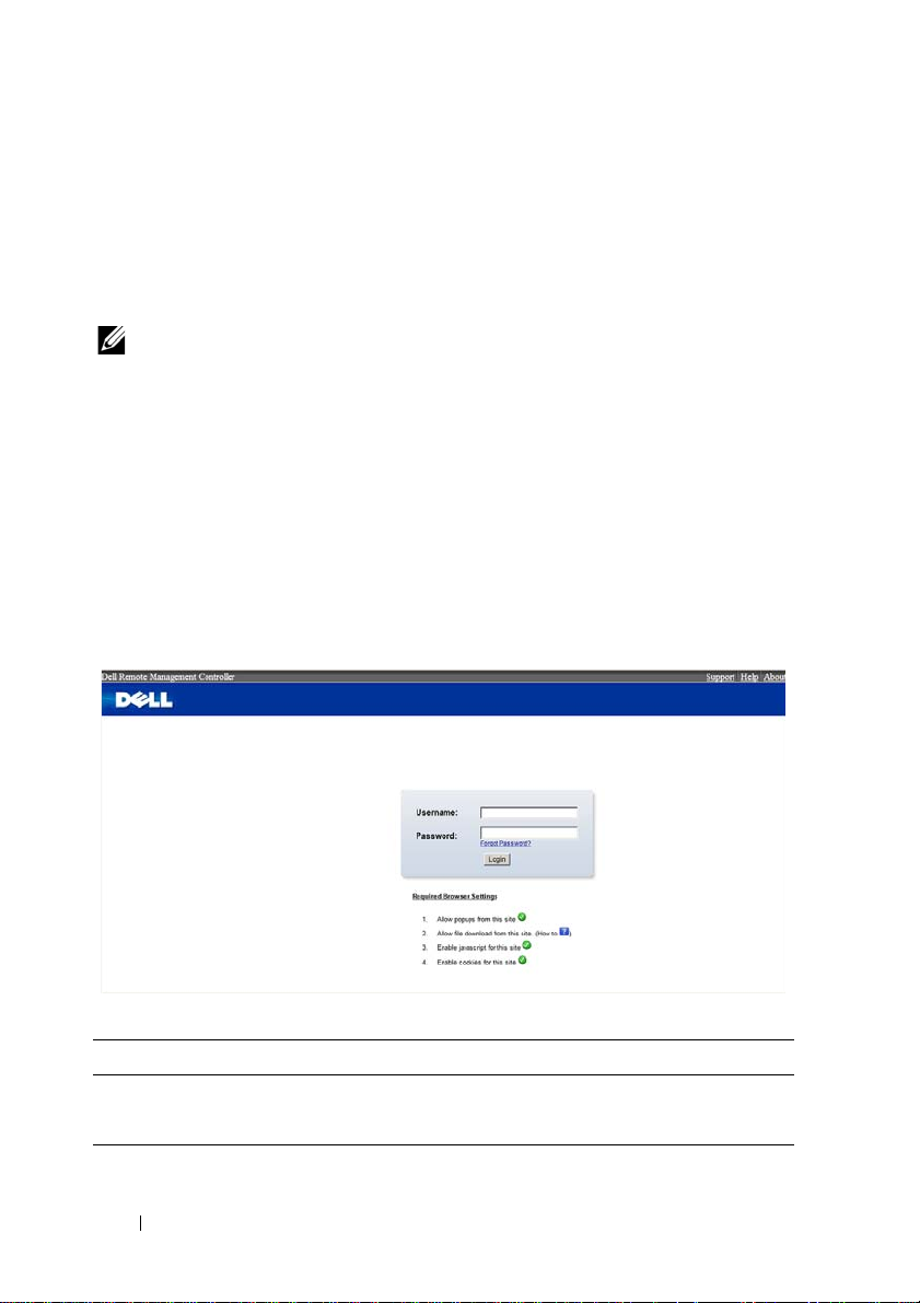
Logging in to the Web User Interface
Enter the IP address or URL (default DHCP\static IP address) into the
address bar of the web browser.
When connecting to the BMC, the login screen prompts for the username
and password. This authentication with Secure Sockets Layer (SSL)
protection prevents unauthorized intruders from gaining access to the BMC
web server. Once authentication is passed, you can manage the server by
privilege.
Table 1-1. Default User Name And Password
Field Default
User Name root
Password root
6
Page 9

NOTE: The default username and password are in lowercase characters. It is
advised to change the root password once you have logged in.
Click the Help button on the top right corner for assistance. Click Logout to
exit.
Table 1-2. Main Page
Menu Item Description
System Information Displays the system information.
FRU Information Displays information for the various FRU devices present in
this system.
Component Displays component information.
Server Identify Displays server identify current status and allows the user to
perform a server identify operation.
Server Health Displays the monitoring status of the server.
Configuration Allows the user to configure the IPMI settings.
Remote Control Allows the user to launch KVM console and perform power
control.
Maintenance Allows the user to do firmware updates.
7
Page 10
System Features
System Information
The System Information page enables you to view the BMC firmware version,
BIOS version, and Chassis version. Click System Information to view the
Remote Management Controller.
Table 1-3. BMC Summary
BMC Information Description
Firmware Revision The revision number of the firmware.
Firmware Build Time Date the firmware was last flashed in the form:
M DD YYYY HH:MM:SS
BIOS Version BIOS version for the system.
Chassis Version Displays the chassis version number.
MB Position Displays the current position of the mainboard within the
chassis.
8
Page 11

Component Information
The Number of CPU Socket field and the Number of Memory Slot field
display the total number of motherboard supported.
CPU Information
Including CPU ID, Status, Socket, Manufacturer, Model, and Frequency.
Memory Information
Including Memory ID, Status, Socket, Module Size, Model, and Frequency.
9
Page 12
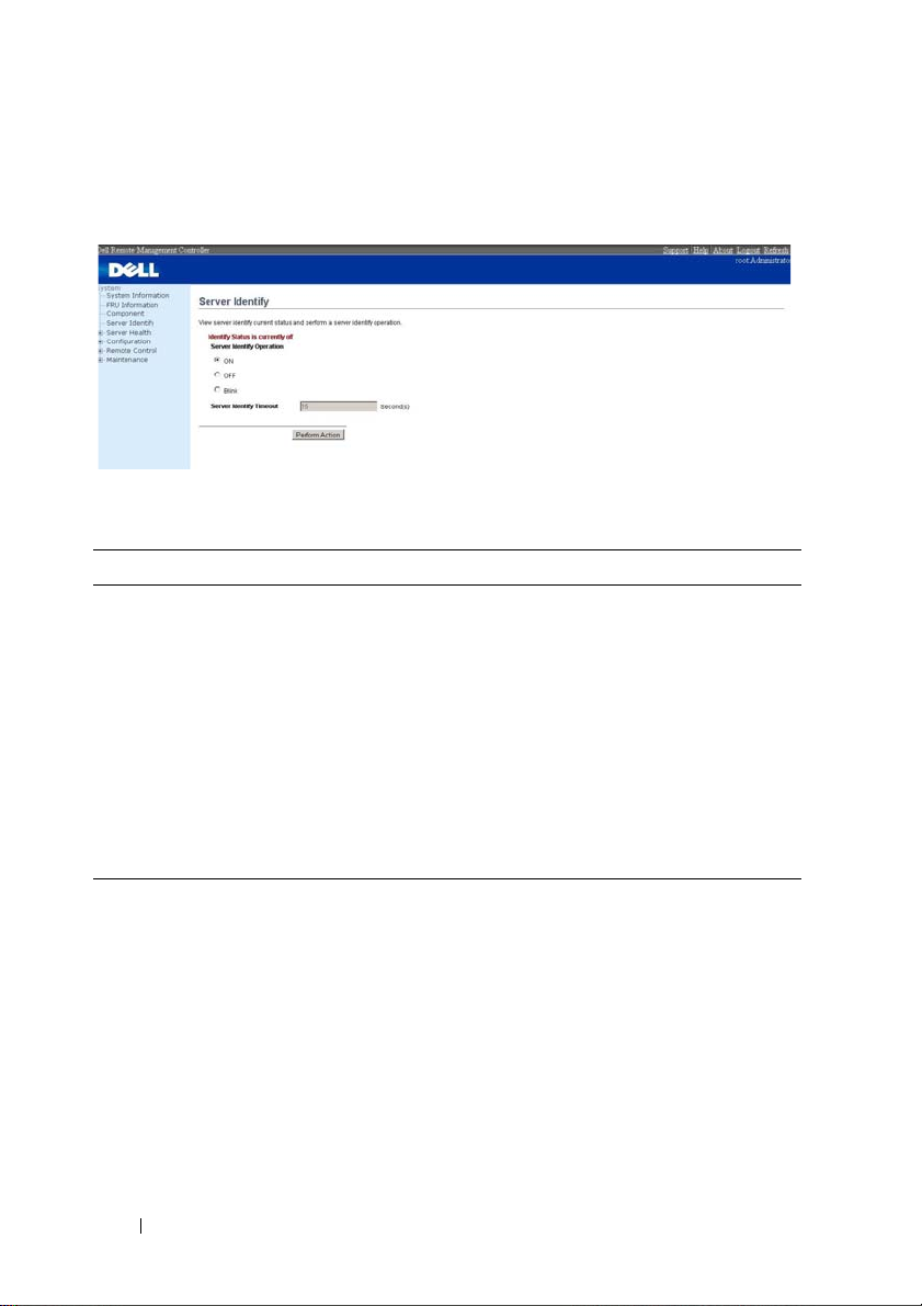
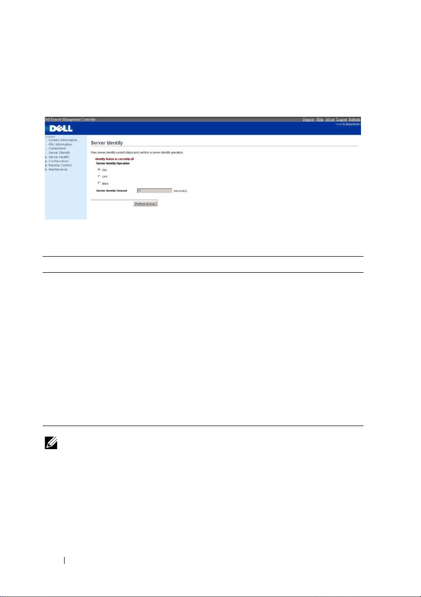
Server Identify
The Server Identify page displays the indicator LED status. You can select a
Server Identify Operation to control the indicator LED functions.
Table 1-4. Server Identify
Item Description
Current Server Identify Displays the current server identify status is on or off.
Server Identify
Operation
Server Identify Timeout You can set the timeout value when you select the Blink
Perform Action Click to execute the selected Server Identify Operation.
Select the server identify LED operation:
• ON
• OFF
• Blink
operation. The range is between 1 to 255 seconds, but note
255s is blinking continuously.
10
Page 13

Firmware Update
Use the Firmware Update feature to upgrade to the latest firmware version.
The following data is included in the BMC firmware package:
• Compiled BMC firmware code and data
• Web-based user interface, JPEG, and other user interface data files
• Default configuration files
Updating the BMC Firmware
NOTE: Before beginning the firmware update, download the latest firmware
version and save it on your local system. During the process of firmware update, the
AC power of the managed system cannot be unplugged and the Web GUI cannot be
closed.
NOTE: Once you enter into Update Mode and choose to cancel the firmware flash
operation, the BMC must be reset. This means that you must close the Internet
browser and log back onto the BMC card before you can perform any other types of
operations.
Select the Enter Update Mode button from the Maintenance tab to put the
device in a special mode that allows firmware update. You can now follow the
instructions presented below to successfully update the card’s firmware. The
device resets if update is cancelled. The device also resets upon successful
completion of firmware update.
1
Browse to, or enter the path on your system where the firmware image file
resides.
Example:
C:\Updates\V1.0\<image_name>
The default firmware image name is s81s
XXX
.bin (whereas XXX is the
version number).
2
Select
Auto Reset BMC
if you want the BMC to auto reset after the
update.
3
BMC will not check if the Firmware image belongs to C5230 platform
when selecting
4
Click the
5
BMC will save configure settings when
Force Update
Upload Firmware
.
button.
Preserve Configuration
is selected.
11
Page 14

6
Click
Start Upgrade
The update might take several minutes. When the update is completed, a
dialog box appears.
7
Click OK to close the session and automatically log out.
8
After the BMC resets, click
.
Log In
to log in to the BMC again.
12
Page 15

Front Panel User Interface
The BMC provides control panel interface functionality including indicators
(fault, status, and ID LEDs) and buttons (power/ID).
Power Button
The power button turns the device on and off.
LEDs
BMC Heartbeat LED
The green LED provides an easy way to indicate that BMC is now enabled.
ID LED
A blinking LED indicates the Chassis Identify command has been accepted.
System Status LED
There is a dual-color LED to show the system status. The BMC turns the
LED off after all event logs are cleared.
The behavior of Status LED and ID LED is listed in Table 1-5.
Table 1-5. LED Status
LED Color Status Occurrence Note
Status LED Amber Blinking See "Blinking Fault
LED Conditions" on
page 14.
Off Normal status
Power LED Green Solid On Power On The power LED status is
Off Power Off
controlled by BIOS.
13
Page 16

Table 1-5. LED Status
LED Color Status Occurrence Note
ID LED Blue Off Normal status (by IPMI
Chassis Identify
command or System ID
Button)
Solid On Identify the system Turn on the ID LED.
Blinking Identify the system with
interval
Heartbeat
LED
Green On BMC is not ready
Blinking BMC is ready
Turn off the ID LED.
1. ipmitool raw 0x00 0x04
0x00
2. ipmitool raw 0x00 0x04
0x00 0x00
1.ipmitool raw 0x00 0x04 0x3c
01
1. IPMI chassis identify
command without request
data ipmitool raw 0x00 0x04
2. IPMI chassis identify
command with only 1
parameter data ipmitool raw
0x00 0x04 0x3c (blink 60 sec)
3. IPMI chassis identify
command with 2 parameter
data ipmitool raw 0x00 0x04
0x3c 0x00 (blink 60 sec)
Table 1-6. Blinking Fault LED Conditions
Index Sensor Name Event Triggers
1 Memory Error 0: Correctable error
1: Uncorrectable error
5: Correctable ECC error logging limit reached
2 POST Error Defined by BIOS and this sensor logged by BIOS.
3 PCIE Error 7: Bus correctable error
8: Bus Uncorrectable error
A: Bus fatal
14
Page 17

Index Sensor Name Event Triggers
4 Temp_CPU
Temp_ Ambient
• Upper Critical Going High
• Upper Non-Critical Going High
Temp_DIMM
Rear Temp
5 Vol tag e Se n sor s
• Upper Critical Going High
• Upper Non-Critical Going High
6 SLED 12V
• Upper Critical Going High
• Upper Non-Critical Going High
7 Fan Sensors
• Lower Critical Going Low
• Lower Non-Critical Going Low
8 BMC Watchdog 0: Timer expired
1: Hard Reset
2: Power Down
3: Power Cycle
9 Processor 0: IERR
1: Thermal Trip
10 BMC SEL 5: SEL almost full (909 x 75% = 681 records)
4: SEL full (909 records)
11 Processor Hot 1: State Asserted
12 System Event 4: PEF action
13 Critical IRQ 0: Front Panel NMI / Diagnostic Interrupt
14 PSU 1 Status
PSU 2 Status
0: Presence detected
1: TEMPERATURE Failure detected
2: IOUT Failure detected
3: VOUT Failure detected
4: FANS Failure detected
5: INPUT Failure detected
15 PSU Redundancy 1: Redundancy lost
15
Page 18

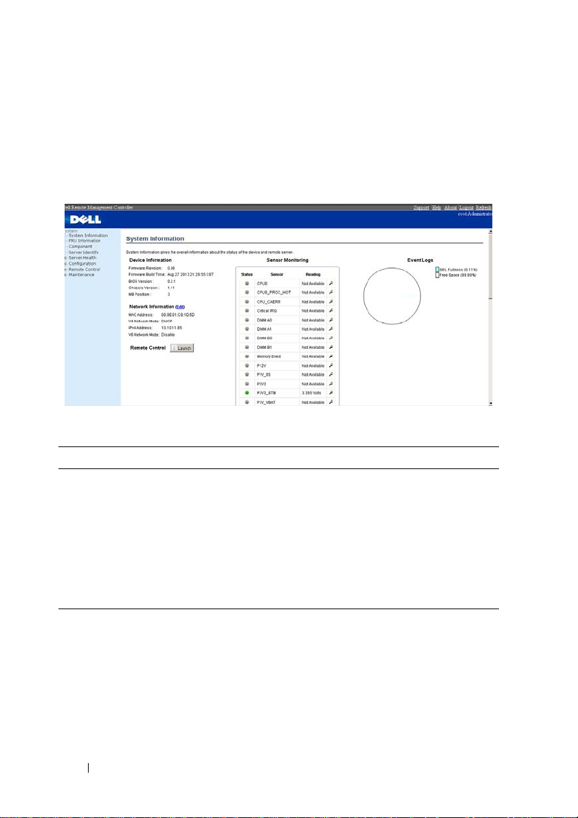
System Information
In MegaRAC GUI, the System Information page gives the overall information
about the status of a device. To open the System Information page, click
System Information from the main menu. A sample screenshot of the System
Information page is shown below.
A brief description of the System Information page is given below.
Device Information
The Device Information displays the following information.
Table 1-7. Device Information description
Item Description
Firmware Revision The revision number of the firmware.
Firmware Build Time This field shows the date and time on which the
firmware is built.
BIOS Version The vision number of the BIOS.
Chassis Version The version of the chassis.
MB Position Displays the mother board position of the chassis.
16
Page 19

Network Information
The Network Information of the device with the following fields is shown
here. To edit the network Information, click Edit.
Table 1-8. Network Information Description
Item Description
MAC Address Read only field showing the IP address of the device.
V4 Network Mode The v4 network mode of the device which could be
either disable, static or DHCP.
IPv4 Address The IPv4 address of the device (could be static or
DHCP).
V6 Network Mode The v6 network mode of the device which could be
either disable, static or DHCP.
IPv6 Address: The IPv6 address of the device.
Remote Control
Start remote redirection of the host by launching the console from this page.
Sensor Monitoring
It lists all the available sensors on the device with the following information’s.
The status column displays the state of the device. There are four states
describe in Table 1-9.
Table 1-9. Sensor Status Description
Status Description
Denotes normal state
Denotes Not Available State
Denotes Warning State
Denotes Critical State
If you click the icon, the sensor page for that particular sensor will be
displayed.
17
Page 20
Event Logs
A graphical representation of all events incurred by various sensors and
occupied/available space in logs can be viewed. If you click on the color-coded
rectangle in the Legend for the chart, you can view a list of those specific
events only.
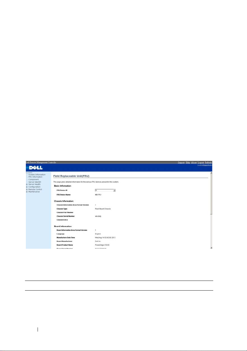
FRU Information
In MegaRAC GUI, the FRU Information Page displays the BMC FRU file
information. The information displayed in this page is Basic Information,
Common Header Information, Chassis Information, Board Information and
Product Information of the FRU device.
To open the FRU Information Page, click FRU Information from the top
menu. Select a FRU Device ID from the Basic Information section to
view the details of the selected device. A screenshot of FRU Information
page is given below.
The following fields are displayed here for the selected device.
Table 1-10. FRU Information
Item Description
Basic Information
FRU device ID Select the device ID from the drop down list.
18
Page 21
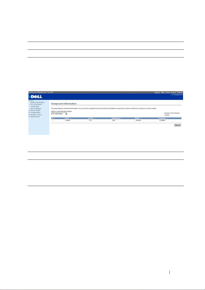
Table 1-10. FRU Information
Item Description
FRU Device Name The device name of the selected FRU device.
Component
This page shows the CPU information and memory information. The
Number of CPU Socket field and the Number of Memory Slot field display
the total number of the motherboard supported.
Table 1-11. Component Information
Item Description
CPU Information Include CPU ID, Status, Socket, Manufacturer, Model
and Frequency.
Memory Information Include memory ID, Status, Socket, Module Size,
Model and Frequency.
19
Page 22
Server Identify
The Server Identify page displays the indicator LED status. You can select a
Server Identify Operation to control the indicator LED.
Table 1-12. Server Identify
Item Description
Current Server Identify
Status
Server Identify Operation Select the server identify LED operation.
Server Identify Timeout You can set the timeout value when you select the
Perform Action Click to execute the selected Server Identify
Displays the current server identity status as on or off.
•ON
•OFF
•Blink
Blink operation, and must between 1 to 255 seconds,
but 255 presents blinking continuously.
Operation.
NOTE: If using “chassis identify force on”, there are three way to make it off.
1. Web UI
2. AC removal
3. BMC reset
20
Page 23
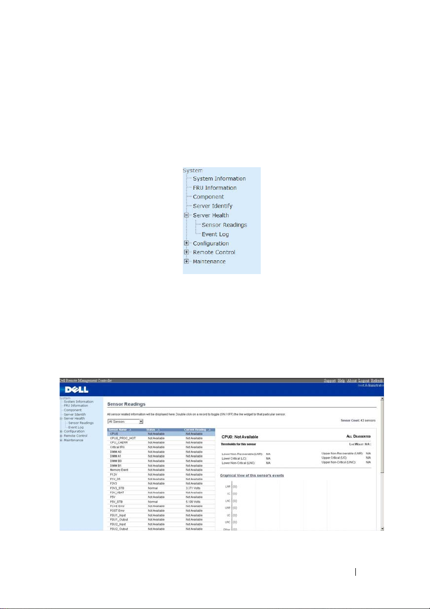
Server Health Group
The Server Health Group consists of two items.
1
Sensor Readings
2
Event Log
The A screenshot displaying the menu items under Server Health is shown
below.
Sensor Readings
In MegaRAC GUI, the Sensor readings Page displays all the sensor related
information. To open the Sensor readings page, click Server Health > Sensor
Readings from the top menu. Click on a record to show more information
about that particular sensor, including thresholds and a graphical
representation of all associated events. A screenshot of Sensor Readings page
is given below.
The Sensor Readings page contains the following information.
21
Page 24

Sensor Type (dropdown menu)
This drop down menu allows you to select the type of sensor. The List of
sensors with the Sensor Name, Status and Current Reading will be displayed
in the list. If you select All Sensors, all the available sensor details will appear
else you can choose the sensor type that you want to display in the list. Some
examples of other sensors include Temperature Sensors, Fan Sensors, and
Voltage Sensors etc.
Select a particular sensor from the list. On the right hand side of the screen
you can view the
Thresholds for this sensor. Thresholds are of six types:
1
Lower Non-Recoverable (LNR)
2
Lower Critical (LC)
3
Lower Non-Critical (LNC)
4
Upper Non-Recoverable (UNR)
5
Upper Critical (UC)
6
Upper Non-Critical (UNC)
The threshold states could be
• Lower Non-critical - going low
• Lower Non-critical - going high
• Lower Critical - going low
• Lower Critical - going high
• Lower Non-recoverable - going low
• Lower Non-recoverable - going high
• Upper Non-critical - going low
• Upper Non-critical - going high
• Upper Critical - going low
• Upper Critical - going high
• Upper Non-recoverable - going low
• Upper Non-recoverable - going high
A graphical view of these events (Number of event logs vs. Thresholds) can be
viewed as shown in the Sensor Readings Page screenshot.
22
Page 25

Live Widget
For the selected sensor, you can click ON or OFF to turn the widget paper or
disappear. This widget gives a dynamic representation of the readings for the
sensor. Given below is a sample screenshot when the widget is on.
NOTE: Widgets are little gadgets, which provide real time information about a
particular sensor. User can track a sensor's behavior over a specific amount of time
at specific intervals. The result will be displayed as a line graph in the widget. The
session will not expire, until the widgets gets a live data of the last widget that is
kept opened.
View this Event Log
You can click here to view the Event Log page for the selected sensor.
Event Log
In MegaRAC GUI, this page displays the list of event logs occurred by the
different sensors on this device. Double click on a record to see the details of
that entry. You can use the sensor type or sensor name filter options to view
those specific events or you can also sort the list of entries by clicking on any
of the column headers.
23
Page 26

To open the Event Log page, click Server Health > Event Log from the top
menu. A sample screenshot of Event Log page is shown below.
The Event Log page consists of the following Fields.
Table 1-13. Even Log
Item Description
Event log Category The category could be either Sensor-Specific Event,
BIOS Generated event or System Management
Software event.
Filter Type The type of filter is listed.
NOTE: Once the Event Log category and Filter type are
selected, the list of events will be displayed with the
Event ID, Time Stamp, Sensor Type, Sensor Name and
Description.
Clear All Event Logs To delete all the existing records for all the sensors.
Procedure:
1
From the
Event Log Category
categories.
2
From the
Filter Type
dropdown list, select the sensor name filer to view
the event for the selected filer.
3
To clear all events from the list, click
24
drop down menu, select the event
Clear All Event Logs
button.
Page 27

Configuration Group
This group of pages allows you to access various configuration settings. A
detailed description of each configuration group is given ahead. A screenshot
of Configuration Group menu is shown below.
A detailed description of the Configuration menu is given ahead.
DNS
The Domain Name System (DNS) is a distributed hierarchical naming
system for computers, services, or any resource connected to the Internet
or a private network. It associates the information with domain names
assigned to each of the participants. Most importantly, it translates domain
names meaningful to humans into the numerical (binary) identifiers
associated with networking equipment for the purpose of locating and
addressing these devices worldwide.
In MegaRAC GUI, the DNS Server settings page is used to manage the DNS
settings of a device.
25
Page 28

To open DNS Server Settings page, click Configuration > DNS from the
main menu. A sample screenshot of DNS Server Settings Page is shown in the
screenshot below.
The fields of DNS Server Settings page are explained below.
Table 1-14. DNS Server Settings
Item Description
Host Configuration
Host Settings Choose either Automatic or Manual settings.
Host Name It displays hostname of the device. If the Host setting
is chosen as Manual, then specify the hostname of the
device.
Register BMC Option to register the BMC either through Direct
Dynamic DNS or through DHCP Client FQDN.
Domain Name Configuration
Domain Settings It lists the option for domain interface as Manual, v4
or v6 for multiLAN channels.
NOTE: If you choose DHCP, then select v4 or v6 for
DHCP servers.
26
Page 29

Table 1-14. DNS Server Settings
Item Description
Domain Name It displays the domain name of the device. If the
Domain setting is chosen as Manual, then specify the
domain name of the device. If you chose Automatic,
the Domain Name cannot be configured as it will be
done automatically. The field will be disabled.
IPv4 Domain Name Server Configuration
DNS Server Settings It lists the option for v4 DNS settings for the device,
Manual and available LAN interfaces.
Preferred DNS Server The DNS (Domain Name System) server v4 address to
be configured to the device.
• IP Address made of 4 numbers separated by dots as in
"xxx.xxx.xxx.xxx".
• Each number ranges from 0 to 255.
• First number must not be 0.
Alternate DNS Server The secondary DNS (Domain Name System) server v4
address to be configured to the device.
• IP Address made of 4 numbers separated by dots as in
"xxx.xxx.xxx.xxx".
• Each number ranges from 0 to 255.
• First number must not be 0.
IPv6 Domain Name Server Configuration
DNS Server Settings It lists the option for v6 DNS settings for the device,
Manual and available LAN interfaces. If you choose
Manual setting, you have to configure the DNS Server
Ip addresses. If you have chosen DHCP, then you have
to select the interface from which the IP address is to
be received. Example of IPv6 address 2001:db8:0::101.
Preferred DNS Server,
Alternate DNS Server
Save To save the entered changes.
Reset To reset the entered changes.
Specify the DNS (Domain Name System) server v6
address to be configured to the device.
27
Page 30

Procedure:
1
Choose the
NOTE: If you choose Automatic, you need not enter the Host Name and if you
choose Manual, you need to enter the Host Name.
2
Enter the
Host Configuration
Host Name
in the given field if you have chosen Manual
either Automatic or Manual.
Configuration.
3
Under
Register BMC
• Check the option
• Choose the option
dynamic DNS or choose
,
Register BMC
to register with this DNS settings.
Direct Dynamic DNS
DHCP Client FQDN
to register with direct
to register through
DHCP server.
4
In the
Domain name Configuration Settings
,
• Select the domain settings from the dropdown list.
• Enter the
5
In
IPv4 Domain Name Server Configuration
• Select the
•In the
•In the
6
In
IPv6 Domain Name Server Configuration
• Select the
•In the
•In the
7
Click
Save
8
Click
Reset
Domain Name
in the given field
DNS Server Settings
Preferred DNS Server
Alternate DNS Server
DNS Server Settings
Preferred DNS Server
Alternate DNS Server
to save the entries.
to reset the entries.
,
, from the dropdown list.
field, enter the preferred IP address.
field, enter the alternate address.
,
, from the dropdown list.
field, enter the preferred IP address.
field, enter the alternate address.
28
Page 31

Mouse Mode
In MegaRAC GUI, Redirection Console handles mouse emulation from local
window to remote screen in either of two methods. User has to be an
Administrator to configure this option. To open Mouse Mode page, click
Configuration > Mouse Mode from the main menu. A sample screenshot of
Mouse Mode Settings Page is shown in the screenshot below.
The fields of Mouse Mode Settings page are explained below.
Table 1-15. Mouse Mode
Item Description
Absolute Mode The absolute position of the local mouse is sent to the
server.
Relative Mode Relative mode sends the calculated relative mouse
position displacement to the server.
NOTE: There is an message, “Relative Mode used for
some OS where the mouse will be out of
synchronization”, shown as below when click Relative
Mode.
Save To save any changes made.
Reset To Reset the modified changes.
29
Page 32

Procedure:
1
Choose either of the following as your requirement:
• Set mode to Absolute
• Set mode to Relative radio
2
Click
Save
button to save the changes made.
3
Click
Reset
to reset the modified changes.
Network
In MegaRAC GUI, the Network Settings Page is used to configure the
network settings for the available LAN channels. To open Network Settings
page, click Configuration > Network from the main menu. A sample
screenshot of Network Settings Page is shown in the screenshot below.
The fields of Network Settings page are explained below.
Table 1-16. Network Settings
Item Description
LAN Interface Lists the LAN interfaces.
LAN Settings To enable or disable the LAN Settings.
MAC Address This field displays the MAC Address of the device.
This is a read only field.
IPv4 Settings This option lists the IPv4 configuration settings.
30
Page 33

Table 1-16. Network Settings
Item Description
Obtain IP Address
automatically
IPv4 Address, Subnet
Mask, and Default
Gateway
This option is to dynamically configure IPv4 address
using DHCP (Dynamic Host Configuration Protocol).
These fields are for specifying the static IPv4 address,
Subnet Mask and Default Gateway to be configured to
the device.
NOTE:
•
IP Address made of 4 numbers separated by dots as in
"xxx.xxx.xxx.xxx".
•
Each Number ranges from 0 to 255.
•
First Number must not be 0.
IPv6 Configuration This option lists the following IPv6 configuration
settings.
IPv6 Settings
Obtain an IPv6 address
automatically
IPv6 Address
This option is to enable the IPv6 settings in the device.
This option is to dynamically configure IPv6 address
using DHCP (Dynamic Host Configuration Protocol).
To specify a static IPv6 address to be configured to the
device. Eg: 2004::2010.
NOTE: When IPv6 Enable and setting DHCP mode, IPv6
address will be assigned of different address each time.
Subnet Prefix length
To specify the subnet prefix length for the IPv6
settings.
NOTE: Value ranges from 0 to 128.
Default Gateway
VLAN Configuration It lists the VLAN configuration settings.
VLAN Settings To enable/disable the VLAN support for selected
VLAN ID The Identification for VLAN configuration.
Specify v6 default gateway for the IPv6 settings.
interface.
• Value ranges from 2 to 4094 (0, 1 for AMI and 4095
reserved).
31
Page 34

Table 1-16. Network Settings
Item Description
VLAN Priority The priority for VLAN configuration.
• Value ranges from 1 to 7.
• 7 is the highest priority for VLAN.
Save To save the entries.
Reset To Reset the modified changes.
Procedure:
1
Select the
2
Check
3
In IPv4 Configuration, enable
automatically
4
If the field is disabled, enter the
Gateway
5
In IPv6 Configuration, if you wish to enable the IPv6 settings, check
Enable
6
If the IPv6 setting is enabled, enable or disable the option
obtaining the IP address automatically
7
If the field is disabled, enter the
Default Gateway
8
In VLAN Configuration, if you wish to enable the VLAN settings, check
Enable
9
Enter the
10
Enter the
11
Click
12
Click
LAN Interface
Enable
to enable the LAN Settings.
from the drop down list.
Use DHCP to Obtain an IP address
to dynamically configure IPv4 address using DHCP.
IPv4 Address, Subnet Mask
in the respective fields.
.
.
IPv6 Address, Subnet Prefix length
in the given field.
.
VLAN ID
VLAN Priority
Save
to save the entries.
Reset
if you want to reset the modified changes.
in the specified field.
in the specified field.
Use DHCP for
and
Default
and
32
Page 35

SNMP
To op en SNMP(Simple Network Management Protocol) page, click
Configuration > SNMP from the main menu. A sample screenshot of SNMP
Page is shown in the screenshot below.
The fields of SNMP Settings Page are explained below.
Table 1-17. SNMP Settings
Item Description
Enable SNMPv1/v2 To enalbe or disable SNMP service.
Read-Only Community
String
Read-Write Community
String
Save To save the new SNMP configuration.
Reset To reset the modified changes.
Community string which allows read only.
Community string which allows read and write access.
33
Page 36

SMTP
Simple Mail Transfer Protocol (SMTP) is an Internet standard for electronic
mail (e-mail) transmission across Internet Protocol (IP) networks. Using
MegaRAC GUI, you can configure the SMTP settings of the device. To open
SMTP Settings page, click Configuration > SMTP from the main menu. A
sample screenshot of SMTP Settings Page is shown in the screenshot below.
The fields of SMTP Settings Page are explained below.
Table 1-18. SMTP Settings
Item Description
Sender Address The 'Sender Address' valid on the SMTP Server.
Machine Name The 'Machine Name' of the SMTP Server.
• Machine Name is a string of maximum 15 alphanumeric characters.
• Space, special characters are not allowed.
Primary SMTP Server Primary SMTP Server configuration.
34
Page 37

Table 1-18. SMTP Settings
Item Description
Server Address The 'IP address' of the SMTP Server. It is a mandatory
field.
NOTE:
•
IP Address made of 4 numbers separated by dots as in
"xxx.xxx. xxx.xxx".
•
Each Number ranges from 0 to 255.
•
First Number must not be 0.
•
Supports IPv4 Address format and IPv6 Address
format.
SMTP Server requires
Authentication
User Name The username to access SMTP Accounts.
To enable/disable SMTP Authentication.
NOTE: SMTP Server Authentication Types supported
are:
•
CRAM-MD5
•
LOGIN
•
PLAIN
If the SMTP server does not support any one of the
above authentication types, the user will get an error
message stating, "Authentication type is not supported
by SMTP Server".
NOTE:
•
User Name can be of length 4 to 64 alpha-numeric
characters.
•
It must start with an alphabet.
•
Special characters ','(comma), ':'(colon),
';'(semicolon), ' '(space) and '\'(backslash) are not
allowed.
35
Page 38

Table 1-18. SMTP Settings
Item Description
Password The password for the SMTP User Account.
NOTE:
•
Password must be at least 4 characters long.
•
White space is not allowed.
•
This field will not allow more than 64 characters.
Secondary SMTP Server It lists the Secondary SMTP Server configuration. It is
an optional field. If the Primary SMTP server is not
working fine, then it tries with Secondary SMTP
Server configuration.
Save To save the new SMTP server configuration.
Reset To reset the modified changes.
Procedure:
1
Enter the
2
Enter the
3
In Primary SMTP Server, enter the
4
Enable the check box
Sender Address
Machine Name
SMTP Server requires Authentication
in the specified field.
in the specified field.
Server Address
in the specified field.
if you want
to authenticate SMTP Server.
5
Enter your
6
In Secondary SMTP Server, enter the
7
Enable the check box
User Name
and
Password
in the respective fields.
Server Address
in the specific field.
SMTP Server requires Authentication
if you want
to authenticate SMTP Server.
8
9
10
Enter your
Click
Click
User Name
Save
to save the entered details.
Reset
to update the entered details.
and
Password
in the respective fields.
36
Page 39

Users
In MegaRAC GUI, the User Management page allows you to view the current
list of user slots for the server. You can add a new user and modify or delete
the existing users. To open User Management page, click Configuration >
Users from the main menu. A sample screenshot of User Management Page is
shown in the screenshot below.
The fields of User Management Page are explained below.
Table 1-19. User Management
Item Description
User ID Displays the ID number of the user.
NOTE: The list contains a maximum of ten users only.
User Name Displays the name of the user.
User Access To enable or disable the access privilege of the user.
Network Privilege Displays the network access privilege of the user.
Email ID Displays email address of the user.
Add User To add a new user.
Modify User To modify an existing user.
Delete User To delete an existing user.
37
Page 40

Procedure:
NOTE: The Free slots are denoted by "~" in all columns for the slot.
Add a new user:
1
To add a new user, select a free slot and click
Add User
User screen as shown in the screenshot below.
2
Enter the name of the user in the
NOTE:
•
User Name is a string of 4 to 16 alpha-numeric characters.
•
It must start with an alphabetical character.
•
It is case-sensitive.
•
Special characters ','(comma), '.'(period), ':'(colon), ';'(semicolon), '
User Name
field.
'(space), '/'(slash), '\'(backslash), '('(left bracket) and ')'(right bracket)
are not allowed.
3
In the
Password
and
Confirm Password
fields, enter and confirm your new
password.
. This opens the Add
NOTE:
•
Password must be at least 8 characters long.
•
White space is not allowed.
•
This field will not allow more than 20 characters.
4
Enable or Disable the
38
User Access
Privilege.
Page 41

5
In the
Network Privilege
field, enter the network privilege assigned to the
user which could be Administrator, Operator, User or No Access. Please
refer to table below for detailed information.
Table 1-20. User Privilege Association between IPMI and Web GUI
Web GUI Privilege List Privilege association between IPMI and Web GUI
Administrator Operator User
login BMC from Web GUI,
SSH and Telnet
configure BMC from Web
GUI
configure users from Web
GUI
clear logs from Web GUI O X X
execute server power control
from Web GUI
virtual KVM redirection O O X
virtual media O O X
6
Check the
NOTE: Password field is mandatory, if SNMP Status is enabled.
7
Choose the SNMP Access level option for user from the
SNMP Status
OOX
OOX
OXX
OOX
check box to enable SNMP access for the user.
SNMP Access
dropdown list. Either it can be Read Only or Read Write.
8
Choose the
Authentication Protocol
to use for SNMP settings from the
drop down list.
NOTE: Password field is mandatory, if Authentication protocol is changed.
9
Choose the Encryption algorithm to use for SNMP settings from the
Privacy protocol
dropdown list.
39
Page 42

10
In the
Email ID
field, enter the email ID of the user. If the user forgets the
password, the new password will be mailed to the configured email address.
NOTE: SMTP Server must be configured to send emails.
Email Format: Two types of formats are available:
AMI-Format:
The subject of this mail format is 'Alert from (your
Hostname)'. The mail content shows sensor information, ex: Sensor
type and Description.
Fixed-Subject Format:
This format displays the message according to
user's setting. You must set the subject and message for email alert.
11
In the
New SSK Key
NOTE: SSH key file should be of pub type.
12
Click
Add
to save the new user and return to the users list.
13
Click
Cancel
field, click Browse and select the SSH key file.
to cancel the modification and return to the users list.
Modify an existing User
1
Select an existing user from the list and click
Add User screen as shown in the screenshot below.
2
Edit the required fields.
3
To change the password, enable the
4
After editing the changes, click
Change Password
Modify
Modify User
. This opens the
option.
to return to the users list page.
40
Page 43

Delete an existing User
To delete an existing user, select the user from the list and click
User
.
NOTE: There is a list of reserved users which cannot be added / modified as BMC
users. Please Refer “MEGARAC SP-X Platform Porting Guide” section “Changing
the Configurations in PMC File-> User Configurations in PMC File” for the list of
reserved users.
Delete
PEF
Platform Event Filtering (PEF) provides a mechanism for configuring the
BMC to take selected actions on event messages that it receives or has
internally generated. These actions include operations such as system poweroff, system reset, as well as triggering the generation of an alert.
In MegaRAC GUI, the PEF Management is used to configure the following:
•Event Filter
• Alert Policy
•LAN Destination
To op en PE F M an ag em en t Settings page, click Configurations > PEF from
the main menu. Each tab is explained below.
41
Page 44

Event Filter Tab
A PEF implementation is recommended to provide at least 16 entries in the
event filter table. A subset of these entries should be pre-configured for
common system failure events, such as over-temperature, power system
failure, fan failure events, etc. Remaining entries can be made available for
’OEM’ or System Management Software configured events. Note that
individual entries can be tagged as being reserved for system use - so this ratio
of pre-configured entries to run-time configurable entries can be reallocated if
necessary.
The fields of PEF Management - Event Filter Tab are explained below.
This page contains the list of configured PEF’s.
Table 1-21. PEF Management - Event Filter
Item Description
PEF ID This field displays the ID for the newly configured
PEF entry (read-only).
Filter configuration Check box to enable the PEF settings.
Event Filter Action Check box to enable PEF Alert action. This is a
mandatory field.
Sensor Name To choose the particular sensor from the sensor list.
Add To add the new event filter entry and return to Event
filter list.
Modify To modify the existing entries.
Cancel To cancel the modification and return to Event filter
list.
42
Page 45

Procedure:
1
Click the
slots
2
To Add an Event Filter entry, select a free slot and click
Add event Filter entry Page. A sample screenshot of Add Event Filter Page
is in seen the screenshot below.
3
In the Event Filter Configuration section,
• PEF ID displays the ID for configured PEF entry (read-only).
• In filter configuration, check the box to enable the PEF settings.
Event Filter
Tab to configure the event filters in the available
Add
to open the
43
Page 46

4
In the Filter Action configuration section,
• Event Filter Action is a mandatory field and checked by default, which
enable PEF Alert action (read-only).
• Select any one of the Power action either Power down, Power reset or
Power cycle from the drop down list
• Choose any one of the configured alert policy number from the drop
down list.
NOTE: Alert Policy has to be configured - under Configuration->PEF->Alert Policy.
5
In the Sensor configuration section,
• Select the type of sensor that will trigger the event filter action.
• In the sensor name field, choose the particular sensor from the sensor
list.
• Choose event option to be either All Events or Sensor Specific Events.
6
Click
Modify
7
Click
Reset
8
Click
Cancel
9
In the Event filter list, click
10
In the Event filter list, click
to accept the modification and return to Event filter list.
to reset the modification done.
to cancel the modification and return to Event filter list.
Modify
Delete
to modify the existing filter.
to delete the existing filter.
44
Page 47

Alert Policy Tab
This page is used to configure the Alert Policy and LAN destination. You can
add, delete or modify an entry in this page.
The fields of PEF Management - Alert Policy Tab are explained below.
Table 1-22. PEF Management - Alert Policy
Item Description
Policy Entry # Displays Policy entry number for the newly configured
entry (read-only).
Policy Number Displays the Policy number of the configuration.
Policy Configuration To enable or disable the policy settings.
45
Page 48

Table 1-22. PEF Management - Alert Policy
Item Description
Policy Set To choose any one of the Policy set values from the
list.
• 0 - Always send alert to this destination.
• 1 - If alert to previous destination was successful, do
not send alert to this destination. Proceed to next
entry in this policy set.
• 2 - If alert to previous destination was successful, do
not send alert to this destination. Do not process any
more entries in this policy set.
• 3 - If alert to previous destination was successful, do
not send alert to this destination. Proceed to next
entry in this policy set that is to a different channel.
• 4 - If alert to previous destination was successful, do
not send alert to this destination. Proceed to next
entry in this policy set that is to a different
destination type.
Channel Number To choose a particular channel from the available
channel list.
Destination Selector To choose a particular destination from the configured
destination list.
NOTE: LAN Destination has to be configured - under
Configuration > PEF > LAN Destination.
Add To save the new alert policy and return to Alert Policy
list.
Modify To modify the existing entries.
Cancel To cancel the modification and return to Alert Policy
list.
46
Page 49

Procedure:
1
In the Alert Policy Tab, select the slot for which you have to configure the
Alert policy. That is, In the
Event Filter Entry
Page, if you have chosen
Alert Policy number as 4, you have to configure the 4th slot (the slot with
Policy Number 4) in the Alert Policy Tab.
2
Select the slot and click
Add
to open the
Add Alert Policy Entry
shown in the screenshot below.
3
Policy Entry #
4
Select the
5
In the
Policy Configuration
is a read only field.
Policy Number
from the list.
field, check
Enable
if you wish to enable the
policy settings.
6
In the
7
Policy Set
In the
Channel Number
field, choose any of the Policy set from the list.
field, choose particular channel from the
available channel list.
8
In the
Destination Selector
field, choose particular destination from the
configured destination list.
Page as
NOTE: LAN Destination has to be configured under:
Configuration > PEF > LAN Destination. That is if you select the number 4 for
destination selector in Alert Policy Entry page, then you have to configure the 4th
slot (LAN Destination Number 4) in the LAN Destination tab.
9
In the
Alert String
field, enable the check box if the Alert policy entry is
Event Specific.
10
In the
Alert String Key
field, choose any one value that is used to look up
the Alert String to send for this Alert Policy entry.
11
Click
Add
to save the new alert policy and return to Alert Policy list.
12
Click
Cancel
to cancel the modification and return to Alert Policy list.
13
In the Alert Policy list, to modify a configuration, select the slot to be
modified and click
Modify
.
47
Page 50

14
In the
Modify Alert Policy Entry
click
Modify
.
15
In the Alert Policy list, to delete a configuration, select the slot and click
Delete
.
PEF Management LAN Destination Page
Page, make the necessary changes and
This page is used to configure the Event filter, Alert Policy and LAN
destination. A sample screenshot of PEF Management LAN Destination
Page is given below.
The fields of PEF Management - LAN Destination Tab are explained below.
Table 1-23. PEF Management - LAN Destination
LAN Destination Displays Destination number for the newly configured
entry (read-only).
Destination Type Destination type can be either an SNMP Trap or an
Email alert.
For Email alerts, the 3 fields - destination Email
address, subject and body of the message needs to be
filled. The SMTP server information also has to be
added - under Configuration > SMTP.
For SNMP Trap , only the des t ination IP address has to
be filled.
48
Page 51

Table 1-23. PEF Management - LAN Destination
Destination Address If Destination type is SNMP Trap, then enter the IP
address of the system that will receive the alert.
Destination address will support the following:
• IPv4 address format.
• IPv6 address format.
If Destination type is Email Alert, then give the email
address that will receive the email.
Subject & Message These fields must be configured if email alert is
chosen as destination type. An email will be sent to the
configured email address in case of any severity events
with a subject specified in subject field and will
contain the message field's content as the email body.
Add To save the new LAN destination and return to LAN
destination list.
Cancel To cancel the modification and return to LAN
destination list.
Procedure:
1
In the
LAN Destination Tab
, choose the slot to be configured. This should
be the same slot that you have selected in the Alert Policy EntryDestination Selector field. That is if you have chosen the Destination
Selector as 4 in the Alert Policy Entry page of Alert Policy Tab, then you
have to configure the 4th slot of LAN Destination Page.
2
Select the slot and click
Add
. This opens the
Add LAN Destination entry
.
3
In the
LAN Destination
field, the destination for the newly configured
entry is displayed and this is a read only field.
4
In the
Destination Type
field, select the one of the types.
49
Page 52

5
In the
Destination Address
NOTE: If Destination type is Email Alert, then give the email address that will
receive the email.
6
Select the
7
In the
8
In the
9
Click
User Name
Subject
Message
Add
field, enter the subject.
field, enter the message.
to save the new LAN destination and return to LAN destination
field, enter the destination address.
from the list of users.
list.
10
Click
Cancel
to cancel the modification and return to LAN destination
list.
11
In the LAN Destination Tab, to modify a configuration, select the row to
be modified and click
12
In the
Modify LAN Destination Entry P
and click
13
In the LAN Destination Tab, to delete a configuration, select the slot and
click
Modify
Delete
.
.
Modify
.
age, make the necessary changes
50
Page 53

SSL
The Secure Socket Layer protocol was created by Netscape to ensure secure
transactions between web servers and browsers. The protocol uses a third
party, a Certificate Authority (CA), to identify one end or both end of the
transactions.
Using MegaRAC GUI, configure SSL certificate into the BMC. Using this,
the device can be accessed in a secured mode.
To open SSL Certificate Configuration page, click Configuration > SSL
from the main menu. There are three tabs in this page.
•
Upload SSL
into the BMC.
• After uploaded, tab function [
information of PEM file uploaded.
•
Generate SSL
configuration details.
• After running [
information of SSL generated.
•
View SSL
NOTE: The way to use command lines below will generate certificate.pem and
key.pem.
1. openssl genrsa -out key.pem 1024
2. openssl req -new -key key.pem -out request.pem
3. openssl x509 -req -days 30 -in request.pem -signkey key.pem -out certificate.pem
more detail please refer to this link:
http://panoptic.com/wiki/aolserver/How_to_generate_selfsigned_SSL_certificates
option is used to upload the certificate and private key file
View SSL
] will show the
option is used to generate the SSL certificate based on
Generate SSL
] successfully, [
View SSL
] will show the
option is used to view the SSL certificate in readable format.
51
Page 54

A sample screenshot of SSL Management Page is shown in the screenshot
below.
The fields of SSL Certificate Configuration - Upload SSL tab are explained
below.
Table 1-24. SSL Certificate Configuration - Upload SSL
Current Certificate Current certificate information will be displayed
(read-only).
New Certificate Certificate file should be of pem type.
Current Privacy Key Current privacy key information will be displayed
(read-only).
New Privacy Key Privacy key file should be of pem type.
Upload To upload the SSL certificate and privacy key into the
BMC.
NOTE: Upon successful upload, HTTPs service will get restarted to use the newly
uploaded SSL certificate.
52
Page 55

The fields of SSL Certificate Configuration - Generate SSL tab are explained
below.
Table 1-25. SSL Certificate Configuration - Generate SSL
Common Name(CN) Common name for which certificate is to be
generated.
• Maximum length of 64 characters.
• Special characters '#' and '$' are not allowed.
Organization(O) Organization name for which the certificate is to be
generated.
• Maximum length of 64 characters.
• Special characters '#' and '$' are not allowed.
Organization Unit(OU) Over all organization section unit name for which
certificate is to be generated.
• Maximum length of 64 characters.
• Special characters '#' and '$' are not allowed.
City or Locality(L) City or Locality of the organization (mandatory).
• Maximum length of 64 characters.
• Special characters '#' and '$' are not allowed.
53
Page 56

Table 1-25. SSL Certificate Configuration - Generate SSL
State or Province(ST) State or Province of the organization (mandatory).
• Maximum length of 64 characters.
• Special characters '#' and '$' are not allowed.
Country(C) Country code of the organization (mandatory).
• Only two characters are allowed.
• Special characters are not allowed.
Email Address Email Address of the organization (mandatory).
Valid for Validity of the certificate.
• Value ranges from 1 to 3650 days.
Key Length The key length bit value of the certificate.
Generate To generate the new SSL certificate.
NOTE: HTTPs service will get restarted, to use the newly generated SSL
certificate.
54
Page 57

The fields of SSL Certificate Configuration - View SSL tab are explained
below.
Table 1-26. SSL Certificate Configuration - View SSL
Basic Information This section displays the basic information about the
uploaded SSL certificate. It displays the following
fields.
•Version
•Serial Number
• Signature Algorithm
•Public Key
55
Page 58

Table 1-26. SSL Certificate Configuration - View SSL
Issued From This section describes the following Certificate Issuer
information.
• Common Name(CN)
• Organization(O)
• Organization Unit(OU)
•City or Locality(L)
•State or Province(ST)
• Country(C)
•Email Address
Validity Information This section displays the validity period of the
uploaded certificate.
•Valid From
•Valid To
Issued To This section display the information about the
certificate issuer.
• Common Name(CN)
• Organization(O)
• Organization Unit(OU)
•City or Locality(L)
•State or Province(ST)
• Country(C)
•Email Address
Procedure:
Upload SSL:
1
Click the
key.
2
Click
3
Click
56
Upload SSL
Upload
to upload the new certificate and privacy key.
View SSL
Tab , B ro ws e t he
New Certificate
and
New Privacy
tab to view the SSL certificate in user readable format.
Page 59

Generate SSL:
1
In
Generate SSL
•The
•The
Common Name
Name of the Organization
tab, enter the following details in the respective fields
for which the certificate is to be generated.
for which the certificate is to be
generated.
•The
Overall Organization Section Unit
name for which certificate to
be generated.
•The
•The
•The
•The
City or Locality
State or Province
Country
email address
of the organization
of the organization.
of the organization
of the organization
• The number of days the certificate will be valid in the
2
Choose the
3
Click
4
Click
Key Length
Generate
View SSL
bit value of the certificate
to generate the certificate.
tab to view the SSL certificate in user readable format.
View SSL:
Click
View SSL
NOTE:
•
Once you Upload/Generate the certificates, only HTTPs service will get
tab to view the SSL certificate in user readable format.
restarted.
•
You can now access your Generic MegaRAC® SP securely using the
following format in your IP Address field from your Internet browser:
https://<your MegaRAC
•
For example, if your MegaRAC® SP?s IP address is 192.168.0.30, enter
®
SP?s IP address here>
the following: https://192.168.0.30
•
Please note the <s> after <http>.You must accept the certificate before
you are able to access your Generic MegaRAC
Val id Fo r
®
SP.
field.
57
Page 60

Web Session
Web Session page, where you can configure the web session timeout seconds
on this page. A screenshot is shown below.
Table 1-27. Web Session
Web session time out setting
• Never Time Out
•Setting Time Out Seconds
NOTE: The time out seconds must be between 60 and
1920.
Save To save the new Web Session configuration.
58
Page 61

Remote Control
The Remote Control consists of the following menu items.
• Console Redirection
• Server Power Control
A sample screenshot of the Remote Control menu is given below.
A detailed description of the menu items are given ahead.
Console Redirection
This page allows you to launch console redirection and to manage the remote
server. To launch it, user must be an Administrator. Click on the "Java
Console" button to launch the Java-based remote console, which will cause
the jviewer.jnlp file to be downloaded. Once the file is downloaded and
launched, a java redirection window will be displayed. A screenshot is shown
below.
NOTE: A compatible JRE must be installed in the system prior to the launch of
JNLP file, and the limit of maximum session is two.
59
Page 62

Many of the available menu options are also available with keystroke
combinations. The following is a list of basic key combinations that may
associate with the menu options available in a particular version of generic
SPX firmware. In the Console redirection Window, you can see the Remote
Host screen, where you can use the mouse and keyboard to control any
operation on the remote host.
Table 1-28. keystroke combinations
Keystroke Description
<ATL> + <R> Start Console Redirection
<ATL> + <P> Stop Console Redirection
<ATL> + <E> Refresh Video
<ATL> + <F> Toggle Full Screen Mode
<ATL> + <C> Show Mouse Cursor
<CTRL>+<F1> About JViewer
60
Page 63

Video
Click Video tab, a drop-down menu items are displayed and each menu items
are explained below.
Table 1-29. Video Description
Item Description
Pause Redirection This menu item can be used to halt Console
Redirection.
Resume Redirection This menu item can be used to resume Console
Redirection.
Refresh Video This menu item can be used to halt Console
Redirection and then restart Console Redirection
again.
Compression Mode This menu item can be used to configure the
compression used. You can select from the following
options:
• YUV420
• YUV444
• YUV444 + 2 color VQ
• YUV444 + 4 color VQ
DCT Quantization Table There are eight levels to select the Video quality.
Host Video Output If you enable this option, the server display will be
blank but you can view the screen in Console
Redirection. If you disable this option, the display will
be back in the server screen.
61
Page 64

Table 1-29. Video Description
Item Description
Full Screen This menu item can be used to view the Console
Redirection in Full Screen mode.
NOTE: Set your client system?s screen resolution to
1024 x 768 so that you can view the server in true full
screen.
Exit This menu item can be used to exit and close the
redirection window.
Keyboard
Click Keyboard tab, a drop-down menu items are displayed and each menu
items are explained below.
Table 1-30. Keyboard Description
Item Description
Hold Right Ctrl Key This menu item can be used to act as the right-side
<CTRL> key when it is in Console Redirection.
Hold Right Alt Key This menu item can be used to act as the right-side
<ALT> key when it is in Console Redirection.
Hold Left Ctrl Key This menu item can be used to act as the left-side
<CTRL> key when in Console Redirection.
Hold Left Alt Key This menu item can be used to act as the left-side
<ALT> key when it is in Console Redirection.
62
Page 65

Table 1-30. Keyboard Description
Item Description
Left Windows Key This menu item can be used to act as the left-side
<WIN> key when it is in Console Redirection. You
can also decide on how to press the key.
•Hold Down
• Press and Release
Right Windows Key This menu item can be used to act as the right-side
<WIN> key when it is in Console Redirection. You
can also decide on how to press the key.
•Hold Down
• Press and Release
Alt+Ctrl+Del This menu item can be used to act as if you depressed
the <CTRL>, <ALT> and <DEL> keys down
simultaneously on the server that you are redirecting.
Context Menu This menu item can be used to act as <Context
Menu> key in Console Redirection.
63
Page 66

Mouse
Click Mouse tab, a drop-down menu items are displayed and each menu
items are explained below.
Table 1-31. Mouse Description
Item Description
Show Cursor This menu item can be used to show or hide the local
mouse cursor on the remote client system.
Lock Single Cursor Only show server's cursor and can't slide out of the
screen.
Mouse Calibration This menu item can be used only when the mouse
mode is relative.
In this step, the mouse threshold settings on the
remote server will be discovered. The local mouse
cursor is displayed in RED color and the remote
cursor is part of the remote video screen. Both the
cursors will be IN SYNCH in the beginning. Please use
'+' or '-' keys to change the threshold settings until
both the cursors go out of synch. Please detect the first
reading for which cursors it goes out of synch. Once
detected, use 'ALT-T' to save the threshold value.
64
Page 67

Options
Click Options tab, a drop-down menu items are displayed and each menu
items are explained below.
Table 1-32. Options Description
Item Description
Bandwidth The Bandwidth Usage option allows you to adjust the
bandwidth. You can select one of the following:
•Auto Detect
• 256 Kbps
• 512 Kbps
•1 Mbps
• 10 Mbps
• 100 Mbps
Keyboard/Mouse Encryption This option allows you to encrypt keyboard inputs and
mouse movements sent between the connections.
65
Page 68

Media
To add or modify a media, select and click 'Virtual Media Wizard' button, a
"Virtual Media" window is displayed, where you can configure the media.
Table 1-33. Media Description
Item Description
Floppy Key Media This menu item can be used to start or stop the
redirection of a physical floppy drive.
NOTE: Floppy Redirection is not an available feature on
all the versions of MegaRAC
CD/DVE Media This menu item can be used to start or stop the
redirection of a physical DVD/CD-ROM drive.
Hard disc/USB Key Media This menu item can be used to start or stop the
redirection of a Disk/USB key image, instead of a
physical driver.
®
SPXs.
66
Page 69

Keyboard Layout
Click Keyboard Layout tab, a drop-down menu items are displayed and each
menu items are explained below.
Table 1-34. Keyboard Layout Description
Item Description
Auto Detect Auto detect keyboard layout
SoftKeyboard It allows selecting the keyboard layout.
67
Page 70

Video Record
Click VideRecord tab, a drop-down menu items are displayed and each menu
items are explained below.
Table 1-35. Video Record Description
Item Description
Start Record This option is to start recording the screen.
Stop Record This option is used to stop the recording.
Settings To set the settings for video recording
Procedure
NOTE: Before you start recording, you have to enter the settings.
1
Click
Video Record > Settings
to open the settings page as shown in the
screenshot below.
2
Enter the
3
Browse and enter the location where you want the video to be saved.
4
Enable the option
5
Click OK to save the entries and return to the Console Redirection screen.
6
Click
7
In the Console Redirection window, click
8
Record the process.
9
To stop the recording, click
Video Length
in seconds.
Normalized video resolution to 1024X768
Cancel
if you don't wish to save the entries.
Video Record > Stop Record
Video Record > Start Record
.
68
.
.
Page 71

Help
Click Help tab, a drop-down menu item is displayed and is explained below.
Table 1-36. Help Description
Item Description
About JViewer Displays the copyright and version information.
69
Page 72

Server Power Control
This page allows you to view and control the power of your server. To open
Power Control and Status page, click Remote Control > Server Power
Control from the main menu. A sample screenshot of Power Control and
Status page is shown in the screenshot below.
The various options of Power Control are given below.
Table 1-37. Power Control and Status
Item Description
Reset Server This option will reboot the system without powering
off (warm boot).
Power Off Server Immediate
Power Off Server - Orderly
Shutdown
Power On Server This option will power on the server.
Power Cycle Server This option will first power off, and then reboot the
Power Cycle Server Click this option to perform the selected operation.
This option will immediately power off the server.
This option will initiate operating system shutdown
prior to the shutdown.
system (cold boot).
70
Page 73

Procedure:
Select an action and click Perform Action to proceed with the selected
action.
NOTE: You will be asked to confirm your choice. Upon confirmation, the command
will be executed and you will be informed of the status.
Maintenance Group
This group of pages allows you to do maintenance tasks on the device. The
menu contains of the following items:
• Firmware Update
• Restore Factory Defaults
A detailed description is given ahead.
Firmware Update
In MegaRAC GUI, this wizard takes you through the process of firmware up
gradation. A reset of the box will automatically follow if the upgrade is
completed or cancelled. An option to preserve configuration will be
presented. Enable it, if you wish to preserve configured settings through the
upgrade.
WARNING : Please note that after entering update mode widgets, other web
pages and services will not work. All open widgets will be closed automatically.
If upgrade process is cancelled in the middle of the wizard, the device will be
reset.
NOTE: The firmware upgrade process is a crucial operation. Make sure that the
chances of a power or connectivity loss are minimal when performing this
operation. Once you enter into Update Mode and choose to cancel the firmware
71
Page 74

flash operation, the MegaRAC® card must be reset. This means that you must close
the Internet browser and log back onto the MegaRAC® card before you can
perform any other types of operations.
To open Firmware Update page, click Maintenance > Firmware Update from
the main menu. A sample screenshot of Firmware Update Page is shown in
the screenshot below.
Procedure:
Click
Enter Update Mode
to upgrade the current device firmware. As
below step by step:
1
Closing all active client requests.
2
Preparing device for firmware upgrade.
3
Uploading firmware image.
4
Verifying firmware image.
5
Flashing firmware image.
6
Resetting Device.
NOTE: You can now follow the instructions presented in the subsequent pages to
successfully update the card?s firmware. The device will reset if update is
canceled. The device will also reset upon successful completion of firmware
update.
72
 Loading...