

Page 1

Dell PowerEdge C5220
Systems
Hardware Owner’s
Manual
Regulatory Model: B04S
Page 2

Notes, Cautions, and Warnings
NOTE: A NOTE indicates important information that helps you make better use of
your system.
CAUTION: A CAUTION indicates potential damage to hardware or loss of data if
instructions are not followed.
WARNING: A WARNING indicates a potential for property damage, personal
injury, or death.
Information in this publication is subject to change without notice.
© 2012 Dell Inc. All rights reserved.
Reproduction of these materials in any manner whatsoever without the written permission of Dell Inc.
is strictly forbidden.
Trademarks used in this text: Dell™, the DELL logo, and PowerEdge™ are trademarks of Dell Inc.
®
Intel
and Intel® Xeon® are registered trademarks of Intel Corporation in the U.S. and other countries.
Microsoft
in the United States and/or other countries. Red Hat
trademarks of Red Hat, Inc. in the United States and/or other countries. SUSE™ is a trademark of
Novell Inc. in the United States and other countries.
Other trademarks and trade names may be used in this publication to refer to either the entities claiming
the marks and names or their products. Dell Inc. disclaims any proprietary interest in trademarks and
trade names other than its own.
®
and Windows® are either trademarks or registered trademarks of Microsoft Corporation
®
and Red Hat Enterprise Linux® are registered
Regulatory Model: B04S
2012-06 Rev. A02
Page 3

Important Information
• Your system must have BIOS version 2.0.1 or later to support Intel Xeon
E3-1200 v2 series processors. You can download the latest version of the
BIOS at support.dell.com.
• Your system must have the BMC version 1.13 or later to support Intel
Xeon E3-1200 v2 series processors. You can download the latest version of
the BMC firmware at support.dell.com.
• Your system must have the Backplane firmware version 1.0.9 or later to
support Intel Xeon E3-1200 v2 series processors. You can download the
latest version of the Backplane firmware at
NOTE: PowerEdge C5220 systems with a service tag on the front panel support only
Intel Xeon E3-1200 series.
Identifying Service Tag on the Front Panel of PowerEdge C5220 Systems.
support.dell.com
.
Page 4

Page 5

Contents
1 About Your System . . . . . . . . . . . . . . . . . . . . . . . . 7
Front-Panel Features and Indicators . . . . . . . . . . . . . . . . . . 8
2 Using the System Setup Program . . . . . . . . . . . . . 17
Start Menu. . . . . . . . . . . . . . . . . . . . . . . . . . . . . . . . 17
BIOS Setup Options at Boot
Console Redirection
Configuring Special Keys
General Help
. . . . . . . . . . . . . . . . . . . . . . . . . . . . . . 20
Server Platform Setup Utility Screens
Main Menu
Advanced Menu
. . . . . . . . . . . . . . . . . . . . . . . . . . . . . . . 22
. . . . . . . . . . . . . . . . . . . . . . . . . . . . . 24
Server Management
Boot Menu
Security Menu
Save and Exit
. . . . . . . . . . . . . . . . . . . . . . . . . . . . . . . . 50
. . . . . . . . . . . . . . . . . . . . . . . . . . . . . . 52
. . . . . . . . . . . . . . . . . . . . . . . . . . . . . . 53
POST Error Handling
Command Line Interfaces for Setup options
. . . . . . . . . . . . . . . . . . . . . . . 18
. . . . . . . . . . . . . . . . . . . . . . . . . . . 18
. . . . . . . . . . . . . . . . . . . . . . . . 19
. . . . . . . . . . . . . . . . . 21
. . . . . . . . . . . . . . . . . . . . . . . . . . . 42
. . . . . . . . . . . . . . . . . . . . . . . . . . 55
. . . . . . . . . . . . . . 58
3 Installing System Components . . . . . . . . . . . . . . . 59
Recommended Tools . . . . . . . . . . . . . . . . . . . . . . . . . . 59
Inside the System
Sled Configuration
. . . . . . . . . . . . . . . . . . . . . . . . . . . . 60
. . . . . . . . . . . . . . . . . . . . . . . . . . . 61
5
Page 6

Sleds . . . . . . . . . . . . . . . . . . . . . . . . . . . . . . . . . . 62
Memory Modules
Hard Drives
Hard Drive Boards
Heat Sinks
Processors
Mezzanine Cards
. . . . . . . . . . . . . . . . . . . . . . . . . . . 64
. . . . . . . . . . . . . . . . . . . . . . . . . . . . . . 69
. . . . . . . . . . . . . . . . . . . . . . . . . . . 76
. . . . . . . . . . . . . . . . . . . . . . . . . . . . . . . 79
. . . . . . . . . . . . . . . . . . . . . . . . . . . . . . . 85
. . . . . . . . . . . . . . . . . . . . . . . . . . . 87
4 Troubleshooting . . . . . . . . . . . . . . . . . . . . . . . . . 99
Troubleshooting Sequence . . . . . . . . . . . . . . . . . . . . . . 99
Update Utilities
BIOS System Update
BIOS Recovery Mode
. . . . . . . . . . . . . . . . . . . . . . . . . . . . 104
. . . . . . . . . . . . . . . . . . . . . . . . . . 109
. . . . . . . . . . . . . . . . . . . . . . . . . 109
5 Jumpers and Connectors. . . . . . . . . . . . . . . . . . 111
System Board Jumpers and Connectors . . . . . . . . . . . . . . . 111
2.5-inch Hard Drive Board Connectors
. . . . . . . . . . . . . . . . 113
3.5-inch Hard Drive Board Connectors
Backplane Connectors
. . . . . . . . . . . . . . . . . . . . . . . . 114
Power Distribution Board Connectors
PDB Power and SMBus Connectors
. . . . . . . . . . . . . . . . 114
. . . . . . . . . . . . . . . . 117
. . . . . . . . . . . . . . . . . 118
6 Getting Help . . . . . . . . . . . . . . . . . . . . . . . . . . . 119
6
Page 7

About Your System
The system includes the following configurations:
• 8-sled system board + 3.5-inch hard drive board + cables.
• 8-sled system board + 2.5-inch hard drive board + cables.
• 8-sled system board + mezzanine card + 3.5-inch hard drive board +
cables.
• 8-sled system board + mezzanine card + 2.5-inch hard drive board +
cables.
• 12-sled system board+ 3.5-inch hard drive board + cables.
• 12-sled system board + 2.5-inch hard drive board + cables.
NOTE: Mixed SATA and SAS hard drives on the 2.5 and 3.5-inch hard drive board
are not supported.
1
About Your System 7
Page 8

Front-Panel Features and Indicators
12
1
2
345
The Dell PowerEdge C5220 server is available in either a 12-sled or 8-sled,
each supporting either two 3.5-inch or four 2.5-inch hard drives.
There are two sled SKUs available for the PowerEdge C5220 server, an eight
sled SKU and a twelve sled SKU. For information on sled population, see
"Sled Configuration" on page 61.
The following section provides information for the 8-sled, 12-sled, and
mezzanine card options.
Features
Figure 1-1. 8-Sled SKU Front Features (Rotated Counterclockwise 90°)
Item Feature Description
1 Mezzanine card cover Cover for the Mezzanine card
2 VGA/USB connector VGA/USB 2.0 connector
3 NIC LAN ports 10/100/1 Gb NIC LAN connector 1
10/100/1 Gb NIC LAN connector 2
4 Power button On/Off button for sled
5 Service Tag Identifying service tag
NOTE: PowerEdge C5220 systems with a service tag on the front panel support
Intel Xeon E3-1200 series processors only.
8 About Your System
Page 9
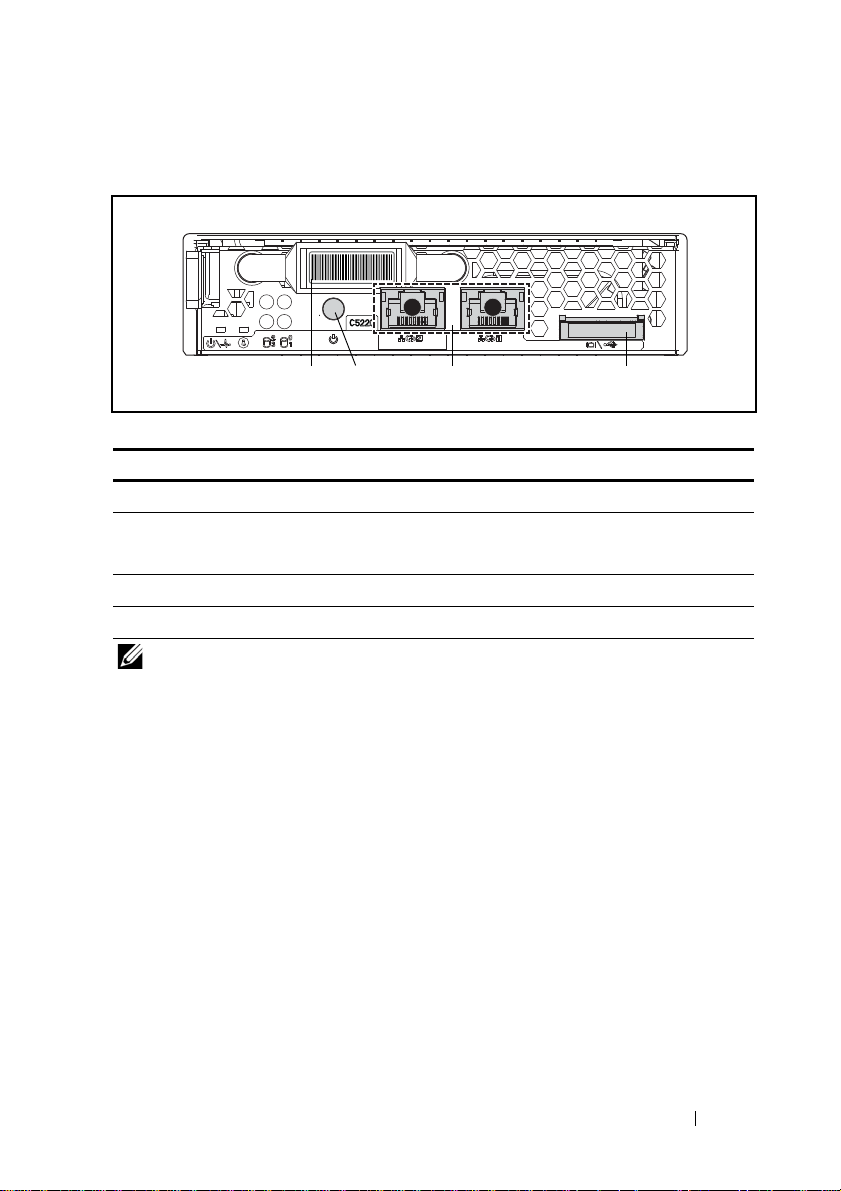
Figure 1-2. 12-Sled SKU Front Features (Rotated Counterclockwise 90°)
12
1234
Item Feature Description
1 VGA/USB connector VGA/USB 2.0 connector
2 NIC LAN ports 10/100/1G NIC LAN connector 1
10/100/1G NIC LAN connector 2
3 Power button On/Off button for sled
4 Service Tag Identifying service tag
NOTE: PowerEdge C5220 systems with a service tag on the front panel support
Intel Xeon E3-1200 series processors only.
About Your System 9
Page 10

Indicators
0
1
3
2
567
1234
Figure 1-3. 8-Sled SKU Front Indicators (Rotated Counterclockwise 90°)
Item Feature Status Description
1, 3 LAN link LED Off No link
2, 4 LAN activity LED Off No activity
LAN link LED
LAN activity LED
LAN link LED
LAN activity LED
LAN link LED
LAN activity LED
LAN link LED
LAN activity LED
5 Hard drive activity
LEDs
Green
Off
Green
Off
Blinking green
Green
Blinking green
Amber
Link
No activity
Link
Activity 10 Mb
Link
Activity 100 Mb
Link
Activity 1Gb
Blinking green Hard drive 0 active
Hard drive 1 active
Hard drive 2 active
Hard drive 3 active
10 About Your System
Page 11

Item Feature Status Description
6 Identity LED Blue
On
Blue
Off
Blinking blue
7 Power/Sta tus Gree n
On
Green
Off
Amber
Off
Blinking amber Event occurred in the
Identifies the system
Normal status
Identifies the system
with an interval
System DC On
System DC Off
Normal status
system
About Your System 11
Page 12

Figure 1-4. 12-Sled SKU Indicators (Rotated Counterclockwise 90°)
1234
5
67
2
0
3
1
Item Feature Status Description
1, 3 LAN link LED Off No link
2, 4 LAN activity LED Off No activity
LAN link LED
LAN activity LED
LAN link LED
LAN activity LED
LAN link LED
LAN activity LED
LAN link LED
LAN activity LED
5 Hard drive activity
LEDs
Green
Off
Green
Off
Blinking green
Green
Blinking green
Amber
Link
No activity
Link
Activity 10 Mb
Link
Activity 100 Mb
Link
Activity 1Gb
Blinking green Hard drive 0 active
Hard drive 1 active
Hard drive 2 active
Hard drive 3 active
12 About Your System
Page 13

6 Identity LED Blue
On
Blue
Off
Blinking blue Identifies the system
7 Power/Sta tus Gree n
On
Green
Off
Amber
Off
Blinking amber Event occurred in the
Identifies the system
Normal status
with an interval
System DC on
System DC off
Normal status
System
About Your System 13
Page 14

Figure 1-5. 1Gb Mezzanine Indicators (Rotated Counterclockwise 90°)
1234
Item Feature Status Description
1, 3 LAN activity LED Off No activity
2, 4 LAN link LED Off No link
LAN link LED
LAN activity LED
LAN link LED
LAN activity LED
LAN link LED
LAN activity LED
LAN link LED
LAN activity LED
Green
Off
Blinking green
Off
Blinking green
Green
Blinking green
Orange
Link
No activity
Link
Activity 10 Mb
Link
Activity 100 Mb
Link
Activity 1 Gb
14 About Your System
Page 15
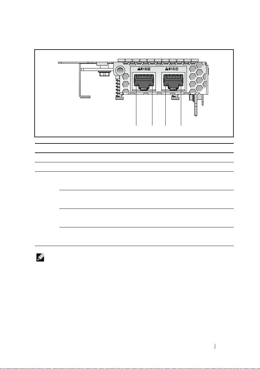
Figure 1-6. 10Gb Mezzanine Indicators (Rotated Counterclockwise 90°)
1234
Item Feature Status Description
1, 3 LAN link LED Off No link
2, 4 LAN activity LED Off No activity
LAN link LED
LAN activity LED
LAN link LED
LAN activity LED
LAN link LED
LAN activity LED
LAN link LED
LAN activity LED
Green
Off
Blinking green
Off
Blinking green
Green
Blinking green
Orange
Link
No activity
Link
Activity 100 Mb
Link
Activity 1Gb
Link
Activity 10 Gb
NOTE: Intel 10Gb mezzanine card is supported by BIOS version 1.0.12 and later.
About Your System 15
Page 16

16 About Your System
Page 17

2
Using the System Setup Program
Start Menu
The system employs the latest AMI Core BIOS, which is stored in Flash
memory. The Flash memory supports the plug-and-play specification, and
contains a BIOS Setup program, the Power On Self Test (POST) routine, and
the PCI auto-configuration utility.
This system board supports system BIOS shadowing enabling the BIOS to
execute from 64-bit onboard write-protected DRAM.
Use the Setup Utility to configure items such as:
• Hard drives and peripherals
• Memory sizing and configuration
• Password protection from unauthorized use
• Protocol and feature enabling/disabling
• Power Management features
This Setup utility should be executed under the following conditions:
• When changing the system configuration
• When a configuration error is detected by the system and you are
prompted to make changes to the Setup utility
• When redefining the communication ports to prevent any conflicts
• When changing the password or making other changes to the security
setup
NOTE: Only items in brackets [ ] can be modified. Items that are not in brackets are
display only.
Using the System Setup Program 17
Page 18

BIOS Setup Options at Boot
The user initiates SETUP by pressing <F2> during POST.
Console Redirection
The console redirection allows a remote user to diagnose and fix problems on
a server, which has not successfully booted to the OS. The centerpiece of the
console redirection is the BIOS Console. The BIOS Console is a Flash ROMresident utility that redirects input and output over a serial or modem
connection.
BIOS supports redirection of both video and keyboard through a serial link
(serial port). After enabling console redirection, the local (host server)
keyboard input and video output are accessible by the local keyboard and
video connections.
Operation through the remote console without the need for a local keyboard
or monitor is also available.
NOTE: Full compatibility and functionality for the available emulation standards
may vary.
Enable/Disable Console Redirection
The console redirection function can be enabled/disabled in the BIOS Setup
menu. See "Remote Access Configuration" on page 46.
18 Using the System Setup Program
Page 19

Configuring Special Keys
Console redirection uses ANSI terminal emulation, which is limited to basic
ASCII characters. There are no function keys, arrow keys, or control keys in
this character set. However, the PowerEdge C5220 software requires the use
of function keys and control keys for ordinary functions. You can emulate a
function key or control key by using a special key sequence called an escape
sequence, to represent a specific key.
For console redirection, an escape sequence starts with an escape character.
This character can be entered in a variety of different ways depending on the
requirements of your terminal emulation software. For example, 0x1b, ^[,
and <Esc> refer to the same escape character.
The following table lists the escape sequence that must be sent to represent a
special key or command.
Key ANSI Escape Sequence Other Sequences
F1 <ESC><Shift>op <ESC>1
F2 <ESC><Shift>oq <ESC>2
F3 <ESC><Shift>or <ESC>3
F4 <ESC><Shift>os <ESC>4
F5 <ESC>5
F6 <ESC>6
F7 <ESC>7
F8 <ESC>8
F9 <ESC>9
F10 <ESC>0
F11 <ESC>!
F12 <ESC>@
Home <ESC>[<Shift>h <ESC>h
End <ESC>[<Shift>k <ESC>k
Ins <ESC>+
Del <ESC>-
Page Up <ESC>?
Using the System Setup Program 19
Page 20

Key ANSI Escape Sequence Other Sequences
Page Down <ESC>/
Reset <ESC>R<ESC>r
<ESC>R
General Help
In addition to the Item Specific Help window, the Setup Utility also provides
a General Help screen. This screen can be called up from any menu by
pressing <F1>. The General Help screen lists the legend keys with their
corresponding alternates and functions. To exit the help window, press the
<Enter> or the <Esc> key.
20 Using the System Setup Program
Page 21

Server Platform Setup Utility Screens
Conventions
The following typographical conventions are used in the tables:
• The text and values in the Setup Item, Options, and Help columns in the
tables are displayed on the BIOS Setup screens.
• Text marked with an * in the Settings column of the tables indicates
default values. These values are not displayed with an * on the setup
screen. The marked text in this document is to serve as a reference point.
• The Comments column provides additional information where it may be
helpful. This information does not appear in the BIOS Setup screens.
• Information in the screen shots that is enclosed in brackets (< >)
indicates variables, depending on the option(s) installed. For example
<Current Date> is replaced by the actual current date.
• Information that is enclosed in square brackets ([ ]) in the tables indicates
areas where the user needs to type in text instead of selecting from a
provided option.
• Whenever information is changed (except Date and Time) the systems
requires a save and reboot to take place. Pressing <ESC> discards the
changes and boot the system according to the boot order set from the last
boot.
Using the System Setup Program 21
Page 22

Main Menu
The Main menu is the screen that is first displayed when you enter BIOS
Setup.
Menu Fields Settings Comments
Main
System Date MM/DD/YYYY Set the Date. Use Tab to
switch between Date
elements.
System Time HH:MM:SS Set the time. Use Tab to
switch between Time
elements.
Product Name Displays the product name.
BIOS Version Displays the BIOS version.
BIOS Build Date Displays the BIOS build
date.
Service Tag Displays the service tag.
22 Using the System Setup Program
Page 23

Menu Fields Settings Comments
Asset Tag Displays the asset tag.
MRC Version Displays the MRC version.
ME Version Displays the ME version.
BMC Version Displays the BMC version.
FAN Control Board FW Displays the fan control
board firmware version.
ePPID Displays the ePPID.
NIC1 MAC Address Displays the NIC1 MAC
address.
NIC2 MAC Address Displays the NIC2 MAC
address.
BMC NIC MAC Address Displays the BMC NIC
MAC address.
Processor Type Displays the processor type.
Processor Speed Displays the processor
speed.
Processor Core Displays the amount of
processor core.
System Memory Size Displays the amount of
system memory.
System Memory Speed Displays the memory
speed.
Using the System Setup Program 23
Page 24

Advanced Menu
The Advanced screen provides an access point to configure several options.
On this screen, the user selects the option that is to be configured.
Configurations are performed on the selected screen, not directly on the
Advanced screen.
CAUTION:
system to malfunction. Unless you have experience adjusting these items, we
recommend that you do not adjust the default values. If the system malfunctions or
does not boot after changing the settings, open BIOS and choose "Load Optimal
Defaults" in the Exit menu to boot up normally.
Menu Fields Settings Comments
Advanced
Power Management Power Management.
CPU Configuration CPU Configuration.
Memory Configuration Memory Configuration.
Incorrect settings to items on the Advanced Menus may cause the
24 Using the System Setup Program
Page 25
Menu Fields Settings Comments
SATA Configuration SATA Devices
Configuration.
PCI Configuration PCI, PCI-X and PCI
Express Settings.
USB Configuration USB Configuration.
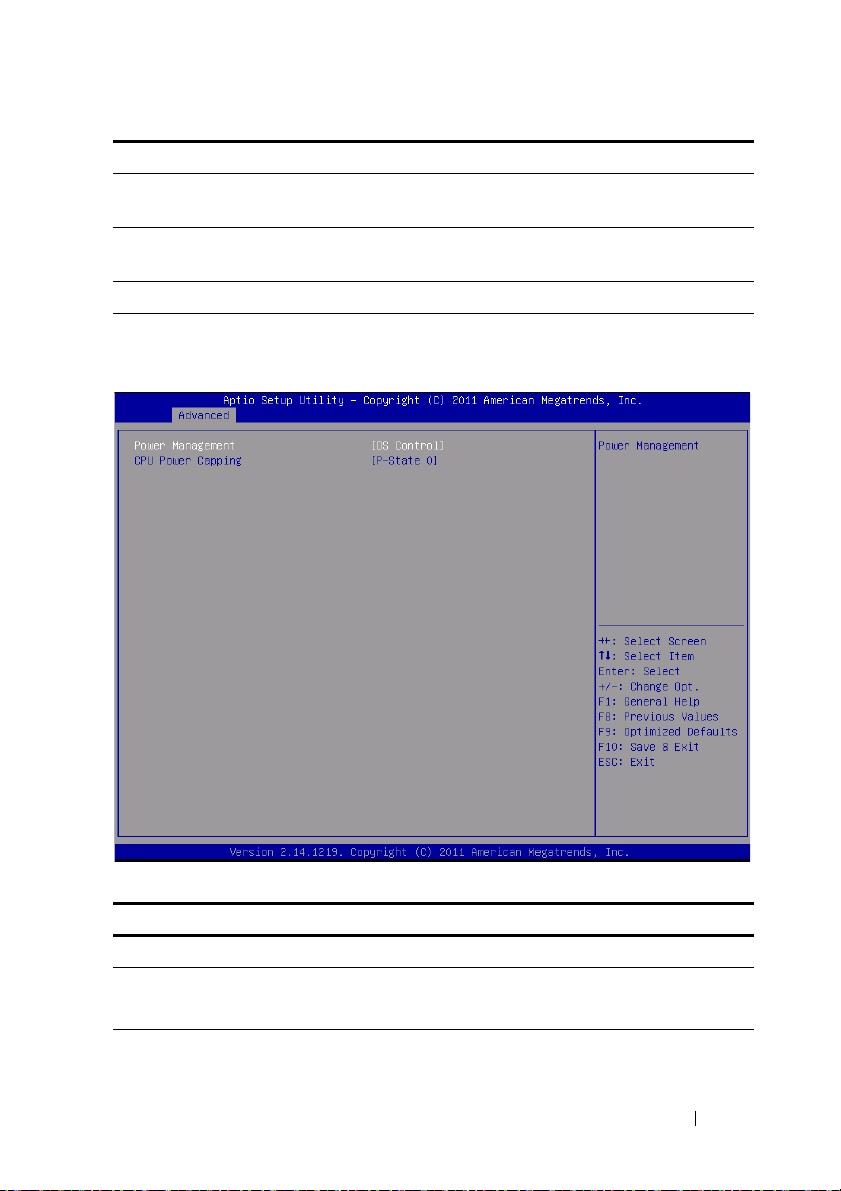
Power Management
Menu Fields Settings Comments
Advanced \Power Management
Power management Maximum Performance
OS Control*
Using the System Setup Program 25
Power management.
Page 26
Menu Fields Settings Comments
CPU power capping P-state 0*
P-state 1
P-state 2
P-state 3
P-state 4
CPU power capping.
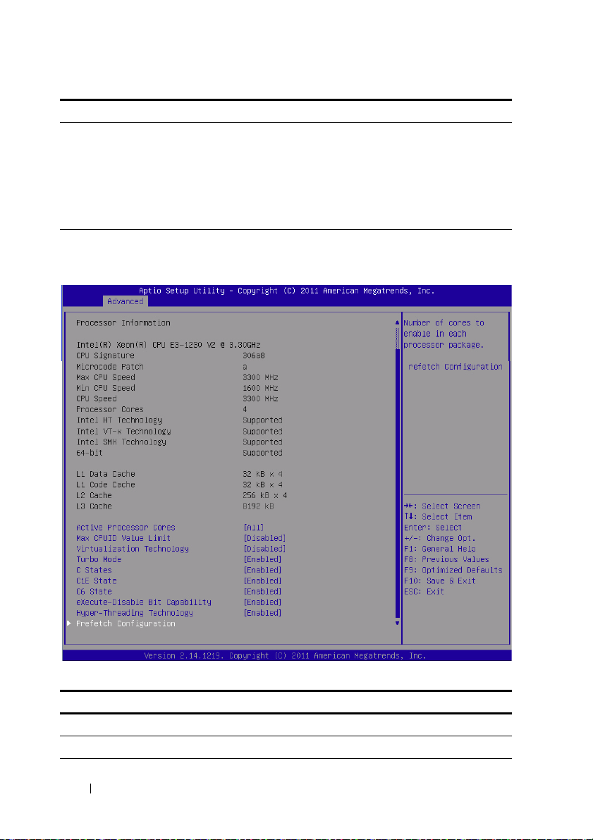
CPU Configuration
Menu Fields Settings Comments
Advanced\CPU Configuration
Processor Information
26 Using the System Setup Program
Page 27

Menu Fields Settings Comments
Active Processor Cores All*
1
2
4
Max CPUID Value Limit Disabled*
Enabled
Virtualization Technology Disabled*
Enabled
Tu r bo Mo de D i sa b le d
Enabled*
C States Disabled
Enabled*
C1E State Disabled
Enabled*
C6 State Disabled
Enabled*
C7 State Disabled
Enabled*
Number of cores to enable
in each processor package.
Some OS’s (NT4) will fail
if the value returned in
EAX is > 3 when CPUID
instruction is executed
with EAX=0. This setting
limits CPUID function to 3
or disable it.
This feature will allow the
users to disable/enable the
VT technology in
applicable CPUs. If disable,
the VT feature is unusable
in any OS.
Tur bo Mo de.
Set to disable, there are no
C states available for the
processor. Set to enable
(default), the processor can
operate in all available
Power C States.
Set C1E disabled/enabled.
Set C6 disabled/enabled.
NOTE: Supported in BIOS
version 2.0.X.
Set C7 disabled/enabled.
NOTE: Supported in BIOS
version 2.0.X.
Using the System Setup Program 27
Page 28
Menu Fields Settings Comments
eXecute-Disable Bit
Capability
Hyper-Threading
Te ch n o lo g y
Prefetch Configuration Prefetch Configuration
Disabled
Enabled*
Disabled
Enabled*
When disable, Intel CPUs
that support the eXecute
Disable (XD) feature will
not report the support to
the operating system.
When enable, Intel CPUs
that support the eXecute
Disable (XD) feature will
report the support to the
operating system.
Disable/Enable HyperThreading Technology.
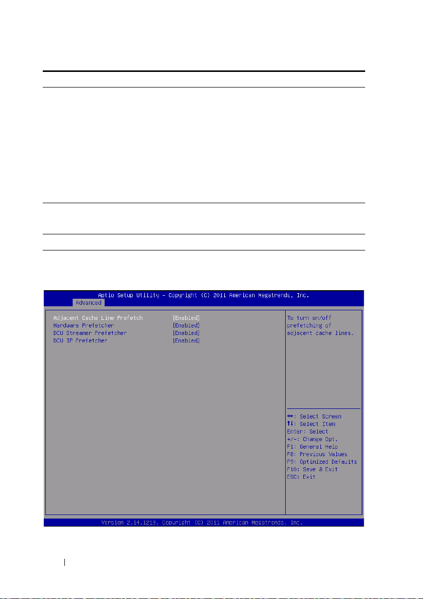
Prefetch Configuration
28 Using the System Setup Program
Page 29

Menu Fields Settings Comments
Advanced\CPU Configuration\Prefetch Configuration
Adjacent Cache Line
Prefetch
Hardware Prefetcher Disable
DCU Streamer Prefetcher Disable
DCU IP Prefetcher Disable
Disable
Enable*
Enable*
Enable*
Enable*
To turn on/off prefetching
of adjacent cache lines.
To turn on/off the Mid
Level Cache (L2) streamer
prefetcher.
Disable/Enable the DCU
Streamer Prefetcher.
Disable/Enable the DCU
IP Prefetcher.
Using the System Setup Program 29
Page 30

Memory Configuration
Menu Fields Settings Comments
Advanced\Memory Configuration
Memory Frequency Auto*
1067 MHz
1333 MHz
Memory Remapping
(3 GB - 4 GB)
Disable*
Enable
Auto-Detect the memory
running speed or set
running speed up to
1067/1333 MHz.
NOTE: Supported detection
and running speed of up to
1600 MHz.
Memory remapping
relocates memory space
3 GB~4 GB to the space
above 4 GB with this
feature disabled/enabled.
30 Using the System Setup Program
Page 31

SATA Configuration
Menu Fields Settings Comments
Advanced\SATA Configuration
Embedded SATA
Controller
Off
IDE
AHCI*
RAID
Disables the SATA
controller or enables it and
sets the device class code as
IDE/AHCI/RAID. This
token applies to the first
on-board SATA controller.
NOTE: Function available
after BIOS 1.0.4.
Using the System Setup Program 31
Page 32

Menu Fields Settings Comments
Embedded SATA Link Rate Auto*
1.5 Gbps
3.0 Gbps
Auto is default mode.
Set SATA port to run on
GEN1 mode by selecting
1.5 Gbps.
NOTE: Function supported
after BIOS 2.0.X.
SATA Port 0/SSI Hard
drive
0
SATA Port1/SSI
drive
1
SATA Port2/
SATA Port3/
SATA Port4/
SATA Port5/
Hard
Hard drive 0 While entering setup,
Hard drive 1 While entering setup,
Hard drive 2 While entering setup,
Hard drive 3 While entering setup,
While entering setup,
BIOS auto detects the
presence of SATA devices
and displays the status of
detected SATA hard drives.
While entering setup,
BIOS auto detects the
presence of SATA devices
and displays the status of
detected SATA hard drives.
BIOS auto detects the
presence of SATA devices
and displays the status of
detected SATA hard drives.
BIOS auto detects the
presence of SATA devices
and displays the status of
detected SATA hard drives.
BIOS auto detects the
presence of SATA devices
and displays the status of
detected SATA hard drives.
BIOS auto detects the
presence of SATA devices
and displays the status of
detected SATA hard drives.
32 Using the System Setup Program
Page 33

Menu Fields Settings Comments
Power Saving Features Disable
Enable*
HDD Security Erase Disable*
Enable
Port Mapping of Cougar Point SATA Controllers
SATA Port0/SSI Hard
Drive 0
SATA Port1/SSI Hard
Drive 1
SATA Port2/Hard Drive 0 Bus0:Dev31:Fun2 SATA Controller
SATA Port3/Hard Drive 1 Bus0:Dev31:Fun2 SATA Controller
SATA Port4/Hard Drive 2 Bus0:Dev31:Fun5 SATA Controller
SATA Port5/Hard Drive 3 Bus0:Dev31:Fun5 SATA Controller
Bus0:Dev31:Fun2 SATA Controller
Bus0:Dev31:Fun2 SATA Controller
Disable/Enable the feature
that allows SATA hard
drives to initiate link power
management transitions.
Not Set Security Freeze
Lock Command.
Using the System Setup Program 33
Page 34

PCI Configuration
Menu Fields Settings Comments
Advanced\PCI Configuration
Embedded Network
Devices
NIC Enumeration Onboard*
Add-in
Active State Power
Management
Configuration
Embedded Network
Devices.
Change the sequence of
NIC OPROM
initialization.
NOTE: Function supported
after BIOS 2.0.X.
Active State Power
Management
Configuration.
34 Using the System Setup Program
Page 35

Menu Fields Settings Comments
PCI Slot Configuration Disable if PCIe card is not
installed.
NOTE: Function supported
after BIOS 2.0.X.
PCIe Generation Gen2*
Gen1
VT for Direct I/O Disable*
Enable
SR-IOV Global Enable Disable*
Enable
Maximum Payload Size Auto*
128 Bytes
256 Bytes
WHEA Support Disable*
Enable
Set PCIe generation.
NOTE: Function supported
after BIOS 2.0.X.
Disable/Enable Intel
Virtualization Technology
for Direct I/O (VT-d) that
enhances I/O support
(DMA) when running a
Virtual Machine Monitor.
Disable/Enable BIOS
support for SR-IOV
devices. To enable this
feature, an add-on NIC
with SR-IOV support is
required.
Auto detects the PCIe
maximum payload size or
sets it to 128/256 Bytes.
Enable or disable Windows
Hardware Error
Architecture (WHEA).
Using the System Setup Program 35
Page 36

Embedded Network Devices
Menu Fields Settings Comments
Advanced\PCI Configuration\Embedded Network Devices
Embedded NIC1 Disabled
Enabled with PXE*
Enabled without PXE
iSCSI Remote Boot
Disable/Enable the
system's primary embedded
network interface
controller (full-function),
w/, w/o including its PXE
boot-ROM or with iSCSI
Remote Boot. To disable
NIC1, NIC2 should be
disabled first. If iSCSI is
enabled, UEFI PXE can
not boot.
36 Using the System Setup Program
Page 37

Menu Fields Settings Comments
Embedded NIC2 Disabled
Enabled with PXE
Enabled without PXE*
iSCSI Remote Boot
Disables/Enables the
system's secondary
embedded network
interface controller (fullfunction), w/, w/o including
its PXE boot-ROM or with
iSCSI Remote Boot. If
iSCSI is enabled, UEFI
PXE can not boot.
Active State Power Management Configuration
Using the System Setup Program 37
Page 38

Menu Fields Settings Comments
Advanced\PCI Configuration\Active State Power Management Configuration
Onboard LAN ASPM Disabled*
L0s
L1
L0s & L1
Mezzing Slot ASPM Disabled*
L0s
L1
L0s & L1
NB-SB Link ASPM Disabled
L0s & L1*
Controls the level of ASPM
supported on the PCI
Express Link.
Controls the level of ASPM
supported on the PCI
Express Link.
Controls the level of ASPM
supported on the PCI
Express Link.
38 Using the System Setup Program
Page 39
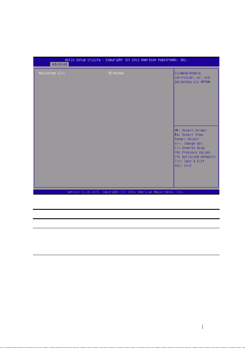
PCI Slot Configuration
Menu Fields Settings Comments
Advanced\PCI Configuration\PCI Slot Configuration
Mezzanine slot Disabled
Enabled*
Enabled without OPROM
Using the System Setup Program 39
Disables/Enables controller,
w/ or w/o OPROM.
Page 40

USB Configuration
Menu Fields Settings Comments
Advanced\USB Configuration
Embedded USB Controller Disabled
Enabled*
Legacy USB Support Disabled
Enabled*
Disables/Enables the builtin USB controller at system
startup.
Enables Legacy USB
support. Disable option
keeps USB devices
available only for EFI
applications.
40 Using the System Setup Program
Page 41

Menu Fields Settings Comments
USB PORT with BMC Disabled
Enabled*
External USB PORT1 Disabled
Enabled*
External USB PORT2 Disabled
Enabled*
Internal USB Connetor Disabled
Enabled*
Allows the users to
electrically disable/enable
the internal USB port
which contacts to BMC.
Allows the users to
electrically disable/enable
the external USB port1.
Allows the users to
electrically disable/enable
the external USB port2.
Disables/Enables the
internal USB port.
Using the System Setup Program 41
Page 42

Server Management
Menu Fields Settings Comments
Server Management
ACPI SPMI Table Disabled
Enabled*
Set BMC LAN
Configuration
Remote Access
Configuration
Restore on AC Power Loss Power Off
Power On*
Last State
ACPI SPMI Table.
Configures BMC network
parameters.
Remote Access
Configuration.
System action to take on
AC power loss.
42 Using the System Setup Program
Page 43

Menu Fields Settings Comments
Power Staggering AC
Recovery
Power Button Disabled
View System Event Log Press <Enter> to view
Clear BMC System Event
Log
Event logging Disabled
NMI On Error Disabled
Immediate*
Random
User Defined
Enabled*
Enabled*
Enabled*
Immediate: PowerOn (No
Delay)\Random:
(Auto)\User Defined: user
defined delay time must be
in the range of Minimum
and Maximum Power On
Delay.
Select Disabled to disable
power off function.
system Event Log records.
Select SEL clear method.
Disable PCIE
SERR/DRAM ECC Error
Logging.
Enable or disable NMI
asserted for fatal error.
Using the System Setup Program 43
Page 44

Set BMC LAN Configuration
Menu Fields Settings Comments
Server Management/BMC Network Configuration
BMC LAN Port
Configuration
BMC NIC IP Source Static
Dedicated-NIC
Shared-NIC*
DHCP*
BMC LAN Port
Configuration
NOTE: Dedicated-NIC port
is found on the chassis.
Select to configure LAN
channel parameters
statically or dynamically
(DHCP).
44 Using the System Setup Program
Page 45

Menu Fields Settings Comments
IP Address xxx.xxx.xxx.xxx Enter IP address in the
form of
XXX.XXX.XXX.XXX (XXX
less than 256 and in
decimal only).
Subnet Mask xxx.xxx.xxx.xxx Enter Subnet Mask in the
form of
XXX.XXX.XXX.XXX (XXX
less than 256 and in
decimal only).
GateWay Address xxx.xxx.xxx.xxx Enter Gateway Address in
decimal in the form of
XXX.XXX.XXX.XXX (XXX
less than 256 and in
decimal only).
Using the System Setup Program 45
Page 46

Remote Access Configuration
Menu Fields Settings Comments
Server/Remote Access Configuration
Remote Access Disabled
Enabled*
The settings specify how
the host computer and the
remote system exchanges
data. Both systems should
have the same or
compatible settings.
NOTE: The screen would
keep 100x31 even when
Remote Access is enabled.
Client console utility should
be supported.
46 Using the System Setup Program
Page 47

Menu Fields Settings Comments
Serial Port Number COM1
COM2 as SOL*
Serial Port Address 3F8h/2F8h*
2F8h/3F8h
Flow Control None*
Hardware
Redirection After BIOS
POST
Term i n al Typ e AN S I*
VT-UTF8 Combo Key
Support
Disabled
Always*
VT100
VT-UTF8
Disabled
Enabled*
Serial port number
COM1/COM2 IO port
address
Flow control can prevent
data loss from buffer
overflow. When sending
data, if the receiving
buffers are full, a 'stop'
signal can be sent to stop
the data flow. Once the
buffers are empty, a 'start'
signal can be sent to restart the flow. Hardware
flow control uses two wires
to send start/stop signals.
Redirection After BIOS
POST
Emulation: ANSI:
Extended ASCII char set.
VT100: ASCII char set.
VT-UTF8: Uses UTF8
encoding to map Unicode
chars onto 1 or more bytes.
Enable VT-UTF8
combination key support
for ANSI/VT100 terminals.
NOTE: BIOS setup screens display at 100 (columns) x 31 (lines). Change the client-side
console utility settings to support 100 (columns) x 31 (lines) for accurate screen display.
Using the System Setup Program 47
Page 48

View System Event Log
48 Using the System Setup Program
Page 49

NOTE: Only provides a brief SEL description for the user. If the user needs more
detailed information, refer to the BMC Event Log in the Server Health of WebUI.
Using the System Setup Program 49
Page 50

Boot Menu
This page enables you to set POST boot parameters.
Menu Fields Settings Comments
Boot
Quiet Boot Disabled
Enabled*
Pause On Errors Disabled*
Enabled
Force PXE Boot Only Disabled*
Enabled
Enables or disables Quiet
Boot option
Pause on Errors
Force PXE Boot Only
50 Using the System Setup Program
Page 51

Menu Fields Settings Comments
Boot Mode BIOS*
UEFI
1st Boot Network*
Hard Disk
RAID
USB Storage
CD/DVD
2nd Boot Network
Hard Disk*
RAID
USB Storage
CD/DVD
3rd Boot Network
Hard Disk
RAID*
USB Storage
CD/DVD
4th Boot Network
Hard Disk
RAID
USB Storage*
CD/DVD
5th Boot Network
Hard Disk
RAID
USB Storage
CD/DVD*
If Boot Mode UEFI/BIOS
is selected, only UEFI
legacy boot devices are
selected for bootup.
Set Boot Priority
Set Boot Priority
Set Boot Priority
Set Boot Priority
Set Boot Priority
Using the System Setup Program 51
Page 52

Security Menu
Menu Fields Settings Comments
Security
Change Supervisor
Password
Change User Password Set User Password
52 Using the System Setup Program
Set Supervisor Password
Page 53

Save and Exit
Menu Fields Settings Comments
Save & Exit
Save Change and Exit Exit system setup after
saving the changes.
Discard Changes and Exit Exit system setup without
saving any changes.
Save Changes Save Changes done so far
to any of the setup option.
Discard Changes Discard changes done so far
to any of the setup option.
Using the System Setup Program 53
Page 54

Menu Fields Settings Comments
Load Optimal Defaults Restore/Load Default
values for all the setup
options.
Load Customized Defaults Restore the User Defaults
to all the setup option.
Save Customized Defaults Save the changes done so
far as User Defaults.
Boot Override
Network Hide if Device is not
connected.
Hard Disk Hide if Device is not
connected.
RAID Hide if Device is not
connected.
USB Storage Hide if Device is not
connected.
CD/DVD ROM Hide if Device is not
connected.
Built-in EFI Shell Attempts to Launch EFI
Shell application
(Shellx64.efi) from one of
the available file system
devices.
NOTE: For further specifications see UEFI Shell Specification at uefi.org/specs/.
54 Using the System Setup Program
Page 55

POST Error Handling
This section provides information on POST error message and handling.
Error Messages
Error messages are displayed at POST under the following fail conditions:
• Hard drive is not present in system
• MRC initialization failure in a DIMM module
NOTE: You can enable the Pause on Error function in the BIOS setup menu to
pause the POST Error Message on Screen at time of display.
Error Message
DIMM A1 has been disabled by MRC.
DIMM A2 has been disabled by MRC.
DIMM A3 has been disabled by MRC.
DIMM A4 has been disabled by MRC.
Status Codes
A status code is a data value used to indicate progress during the boot phase.
A subset of these status codes, known commonly as checkpoints, indicate
common phases of the BIOS boot process.
The status codes can be viewed during POST at the right bottom corner of
the screen as shown in Figure 2-1.
Using the System Setup Program 55
Page 56

Figure 2-1. POST Error Codes
Status Codes
Status Code Description
0x90 Boot Device Selection (BDS) phase is started
0x91 Driver connecting is started
0x92 PCI Bus initialization is started
0x94 PCI Bus Enumeration
0x95 PCI Bus Request Resources
0x96 PCI Bus Assign Resources
0x97 Console Output devices connect
0x98 Console input devices connect
0x99 Super IO Initialization
0x9A USB initialization is started
0x9B USB Reset
0x9C USB Detect
56 Using the System Setup Program
Page 57

Status Code Description
0x9D USB Enable
0xA0 IDE initialization is started
0xA1 IDE Reset
0xA2 IDE Detect
0xA3 IDE Enable
0xA4 SCSI initialization is started
0xA5 SCSI Reset
0xA6 SCSI Detect
0xA7 SCSI Enable
0xA8 Setup Verifying Password
0xA9 Start of Setup
0xAB Setup Input Wait
0xAD Ready To Boot event
0xAE Legacy Boot event
0xAF Exit Boot Services event
0xB2 Legacy Option ROM Initialization
0xB3 System Reset
0xB4 USB hot plug
Using the System Setup Program 57
Page 58

Command Line Interfaces for Setup options
The SETUP menu provides setup options through the system configuration
utility (syscfg), included in the Dell OpenManage Deployment Toolkit
(DTK).
Users can use the utility as following:
To change the SETUP option thru D4 token:
./syscfg –t=D4_token_id
Example:
./syscfg -t=0x002D to enable NIC1
To check token active status:
./syscfg --istokenactive=D4_token_id
Example:
./syscfg --istokenactive=0x002D to check the token active status of NIC1
To di rec t ly ch ang e t he S ET UP option thru BMC memory:
./ipmitool raw <command> <data>
Example:
./ipmitool raw 0xc 1 1 3 10 106 42 120 to set IP address of BMC LAN port
as 10.106.42.120
58 Using the System Setup Program
Page 59

3
Installing System Components
Safety Measures
CAUTION: Many repairs may only be done by a certified service technician. You
should only perform troubleshooting and simple repairs as authorized in your
product documentation, or as directed by the online or telephone service and
support team. Damage due to servicing that is not authorized is not covered by
warranty. Read and follow the safety instructions that came with the product.
System components and electronic circuit boards can be damaged by
discharges of static electricity. Working on systems that are still connected to
a power supply can be extremely dangerous. To avoid injury to yourself or
damage to system, follow these guidelines:
• If possible, wear a grounded wrist strap when you are working inside the
system chassis. Alternatively, discharge any static electricity by touching
the bare metal chassis of the system chassis, or the bare metal body of any
other grounded appliance.
• Hold electronic circuit boards by the edges only. Do not touch the
components on the board unless it is necessary to do so. Do not flex or
stress the circuit board.
• Leave all components inside the static-proof packaging until you are ready
to use the component for the installation.
Recommended Tools
•Phillips screwdriver #2
Installing System Components 59
Page 60

Inside the System
8
7
6
5
1
3
2
4
CAUTION: Many repairs may only be done by a certified service technician. You
should only perform troubleshooting and simple repairs as authorized in your
product documentation, or as directed by the online or telephone service and
support team. Damage due to servicing that is not authorized is not covered by
warranty. Read and follow the safety instructions that came with the product.
CAUTION: This system must be operated with the system cover installed to make
sure of proper cooling.
Figure 3-1. Inside the System
1 PSU 1 2 PSU 2
3 PDB 1 4 PDB 2
5 power socket bracket 6 fan cage
7 backplane 8 sleds (12)
60 Installing System Components
Page 61

Sled Configuration
PSU1 PSU2
PSU1 PSU2
1 2 3 4 5 6 7 8
1 2 3 4 5 6 7 8 9 10 11 12
CAUTION: Many repairs may only be done by a certified service technician. You
should only perform troubleshooting and simple repairs as authorized in your
product documentation, or as directed by the online or telephone service and
support team. Damage due to servicing that is not authorized by Dell is not covered
by your warranty. Read and follow the safety instructions that came with the
product.
The following illustrations show the two server sled options and the sled
numbering in each option.
Figure 3-2. PowerEdge C5220 8-Sled SKU
NOTE: Sled SKU may also include an LSI 2008, 1GbE or 10GbE mezzanine card.
Figure 3-3. PowerEdge C5220 12-Sled SKU
Installing System Components 61
Page 62

Sleds
2
1
Removing a Sled
CAUTION:
should only perform troubleshooting and simple repairs as authorized in your
product documentation, or as directed by the online or telephone service and
support team. Damage due to servicing that is not authorized by Dell is not covered
by your warranty. Read and follow the safety instructions that came with the
product.
CAUTION: To ensure proper airflow in the system, if a sled is removed it should be
immediately replaced with another sled or sled dummy.
1
Press the release latch down .
2
Pull the sled out of the system .
Many repairs may only be done by a certified service technician. You
62 Installing System Components
Page 63

Installing a Sled
CAUTION: Many repairs may only be done by a certified service technician. You
should only perform troubleshooting and simple repairs as authorized in your
product documentation, or as directed by the online or telephone service and
support team. Damage due to servicing that is not authorized by Dell is not covered
by your warranty. Read and follow the safety instructions that came with the
product.
CAUTION: To ensure proper airflow in the system, if a sled is removed it should be
immediately replaced with another sled or sled dummy.
Push the sled into the system until flush with the case and the release latch
locks.
Installing System Components 63
Page 64

Memory Modules
Supported DIMM Configuration
The following DIMM configurations are supported by the system.
Figure 3-4. DIMM Slot Configuration
DIMM Population Rules
For a single DIMM, only install in DIMM A1.
For two DIMMs, install in DIMM A1 + A3.
64 Installing System Components
Page 65

Supported Memory
NOTE: Only Intel Xeon E3-1200v2 family of products support 1600 MHz memory.
Supported Memory
Configura-
Memory Type/Size CPU DIMMs Type Memory
tion
8-Sled
8-sled
8-sled
8-sled
8-sled
8-sled
8-sled
8-sled
8-sled
8-sled
8-sled
8-sled
8-sled
8-sled
8-sled
8-sled
8-sled
DDR3 ECC
UDIMM/2048 MB*1
DDR3 ECC
UDIMM/2048 MB*2
DDR3 ECC
UDIMM/2048 MB*3
DDR3 ECC
UDIMM/4096 MB*1
+2048 MB*2
DDR3 ECC
UDIMM/2048 MB*1
+4096 MB*2
DDR3 ECC
UDIMM/4098 MB*3
DDR3 ECC
UDIMM/2048 MB*4
DDR3 ECC
UDIMM/4096 MB*1
DDR3 ECC
UDIMM/4096 MB*2
DDR3 ECC
UDIMM/2048 MB*2
+4096 MB*2
DDR3 ECC
UDIMM/4096 MB*4
DDR3 ECC
UDIMM/8912 MB*1
DDR3 ECC
UDIMM/8912 MB*2
DDR3 ECC
UDIMM/8912 MB*3
DDR3 ECC
UDIMM/8912 MB*4
DDR3 ECC
UDIMM/8912 MB*2
+2048 MB*2
DDR3 ECC
UDIMM/8912
MB*2+4096MB*2
1 1 UDIMM 1333/
1 2 UDIMM 1333/
1 3 UDIMM 1333/
1 3 UDIMM 1333/
1 3 UDIMM 1333/
1 3 UDIMM 1333/
1 4 UDIMM 1333/
1 1 UDIMM 1333/
1 2 UDIMM 1333/
1 4 UDIMM 1333/
1 4 UDIMM 1333/
1 1 UDIMM 1333/
1 2 UDIMM 1333/
1 3 UDIMM 1333/
1 4 UDIMM 1333/
1 4 UDIMM 1333/
1 4 UDIMM 1333/
Rank Type
Speed
(MHz)
1R x8 2 Gb 2G •
1600
1R x8 2 Gb 4G • •
1600
1R x8 2 Gb 6G • • •
1600
2R/1Rx8 2 Gb 8G 2G 4G 2G
1600
1R/2Rx8 2 Gb 10G 2G 4G 4G
1600
2R x8 2 Gb 12G • • •
1600
1R x8 2 Gb 8G • • • •
1600
2R x8 2 Gb 4G •
1600
2R x8 2 Gb 8G • •
1600
1R/2Rx8 2 Gb 12G 2G 4G 2G 4G
1600
2R x8 2 Gb 16G • • • •
1600
2R x8 4 Gb 8G
1600
2R x8 4Gb 16G • •
1600
2R x8 4Gb 24G • • •
1600
2R x8 4Gb 32G • • • •
1600
2R/1Rx8 4Gb/
1600
2R/2Rx8 4Gb/ 2Gb 24G 4G 8G 4G 8G
1600
(x8, x4)
Component
Density
2Gb
Total
Size
20G 2G 8G 2G 8G
DIMM Slot
A1 A2 A3 A4
•
Installing System Components 65
Page 66

Supported Memory
Configura-
Memory Type/Size CPU DIMMs Type Memory
tion
12 sled
12 sled
12 sled
12 sled
12 sled
12 sled
12 sled
12 sled
12 sled
12 sled
12 sled
12 sled
12 sled
12 sled
12 sled
12 sled
12 sled
DDR3 ECC
UDIMM/2048 MB*1
DDR3 ECC
UDIMM/2048 MB*2
DDR3 ECC
UDIMM/2048 MB*3
DDR3 ECC
UDIMM/4096 MB*1
+2048 MB*2
DDR3 ECC
UDIMM/2048 MB*1
+4096 MB*2
DDR3 ECC
UDIMM/4098 MB*3
DDR3 ECC
UDIMM/2048 MB*4
DDR3 ECC
UDIMM/4096 MB*1
DDR3 ECC
UDIMM/4096 MB*2
DDR3 ECC
UDIMM/2048
MB*2+4096 MB*2
DDR3 ECC
UDIMM/4096 MB*4
DDR3 ECC
UDIMM/8912MB*1
DDR3 ECC
UDIMM/8912MB*2
DDR3 ECC
UDIMM/8912MB*3
DDR3 ECC
UDIMM/8912MB*4
DDR3 ECC
UDIMM/8912MB*2
+2048MB*2
DDR3 ECC
UDIMM/8912MB*2
+4096MB*2
11 VLP
12 VLP
13 VLP
13 VLP
13 VLP
13 VLP
14 VLP
11 VLP
12 VLP
14 VLP
14 VLP
11 VLP
12 VLP
13 VLP
14 VLP
14 VLP
14 VLP
UDIMM
UDIMM
UDIMM
UDIMM
UDIMM
UDIMM
UDIMM
UDIMM
UDIMM
UDIMM
UDIMM
UDIMM
UDIMM
UDIMM
UDIMM
UDIMM
UDIMM
Rank Type
Speed
(MHz)
1333/
2R x8 1Gb 2G •
1600
1333/
2R x8 1Gb 4G • •
1600
1333/
2R x8 1Gb 6G • • •
1600
1333/
2R x8 2Gb/
1600
1333/
2R x8 1Gb/
1600
1333/
2R x8 2Gb 12G • • •
1600
1333/
2R x8 1Gb 8G • • • •
1600
1333/
2R x8 2Gb 4G •
1600
1333/
2R x8 2Gb 8G • •
1600
1333/
2R x8 1Gb/2Gb 12G 2G 4G 2G 2G
1600
1333/
2R x8 2Gb 16G • • • •
1600
1333/
2R x8 4Gb 8G •
1600
1333/
2R x8 4Gb 16G • •
1600
1333/
2R x8 4Gb 24G • • •
1600
1333/
2R x8 4Gb 32G • • • •
1600
1333/
2R x8 4Gb/2Gb 20G 2G 8G 2G 8G
1600
1333/
2R x8 4Gb/2Gb 24G 4G 8G 4G 8G
1600
(x8, x4)
Component
Density
1Gb
2Gb
Total
Size
8G 2G 4G 2G
10G 2G 4G 4G
DIMM Slot
A1 A2 A3 A4
NOTE: 1600MHz VLP UDIMM will be available by June 2012.
66 Installing System Components
Page 67

Removing a Memory Module
1
2
3
WARNING: The memory modules are hot to touch for some time after the system
has been powered down. Allow time for the memory modules to cool before
handling them. Handle the memory modules by the card edges and avoid touching
the components on the memory module.
CAUTION: Many repairs may only be done by a certified service technician. You
should only perform troubleshooting and simple repairs as authorized in your
product documentation, or as directed by the online or telephone service and
support team. Damage due to servicing that is not authorized is not covered by
warranty. Read and follow the safety instructions that came with the product.
1
Remove the sled from the system. See "Sled Configuration" on page 61.
2
Push the locking latches of the DIMM slot outwards. See Figure 3-5.
3
Remove the memory module from the system.
Figure 3-5. Removing and Installing a Memory Module
1 locking latch 2 DIMM slot
3 memory module notch
Installing System Components 67
Page 68

Replacing a Memory Module
WARNING: The memory modules are hot to touch for some time after the system
has been powered down. Allow time for the memory modules to cool before
handling them. Handle the memory modules by the card edges and avoid touching
the components on the memory module.
CAUTION: Many repairs may only be done by a certified service technician. You
should only perform troubleshooting and simple repairs as authorized in your
product documentation, or as directed by the online or telephone service and
support team. Damage due to servicing that is not authorized is not covered by
warranty. Read and follow the safety instructions that came with the product.
The system board has four slots in two channels for the installation of
memory modules. See "System Board Jumpers and Connectors" on page 111
for the location of the memory modules.
Follow the instructions given below to install memory modules:
1
Align the memory module correctly with the DIMM slot. Note the notch
and obstruction in Figure 3-5.
2
Press the edge connector of the memory module into the DIMM slot. Press
down firmly on the memory module so that the locking latches of the
DIMM slot are levered upwards to secure the memory module in place.
68 Installing System Components
Page 69

Hard Drives
Bottom of sled
Top of sled
The following are examples showing the installation and removal procedures
for the 2.5-inch and the 3.5-inch hard drives.
Removing a 2.5-inch Hard Drive
CAUTION: Many repairs may only be done by a certified service technician. You
should only perform troubleshooting and simple repairs as authorized in your
product documentation, or as directed by the online or telephone service and
support team. Damage due to servicing that is not authorized by Dell is not covered
by your warranty. Read and follow the safety instructions that came with the
product.
NOTE: Mixing SATA and SAS hard drive on the 2.5 and 3.5-inch hard drive board is
not supported.
1
Remove the sled from the system. See "Sled Configuration" on page 61.
2
Remove the hard drive from the sled docking bay.
3
Select the hard drive to replace and remove the four hard drive bracket
screws securing it underneath the sled.
Remove the hard drive from the sled docking bay.
4
Installing System Components 69
Page 70

5
HDD0
2.5” HDD
HDD1
2.5” HDD
HDD2
2.5” HDD
HDD3
2.5” HDD
Remove the four screws from the 2.5-inch hard drive bracket, then detach
the hard drive from the bracket.
70 Installing System Components
Page 71

Installing a 2.5-inch Hard Drive
HDD0
2.5” HDD
HDD1
2.5” HDD
HDD2
2.5” HDD
HDD3
2.5” HDD
1
Align the 2.5-inch hard drive bracket on the new hard drive then replace
the four screws.
NOTE: The correct orientation of the bracket with the arrow mark pointing towards
the hard drive connector.
2
Connect the hard drive to the hard drive board in the sled.
Replace the sled hard drive bracket screws underneath the sled.
3
Installing System Components 71
Page 72

Removing a 3.5-inch Hard Drive
CAUTION: Many repairs may only be done by a certified service technician. You
should only perform troubleshooting and simple repairs as authorized in your
product documentation, or as directed by the online or telephone service and
support team. Damage due to servicing that is not authorized by Dell is not covered
by your warranty. Read and follow the safety instructions that came with the
product.
NOTE: Mixing SATA and SAS hard drives on the 2.5 and 3.5-inch hard drive board is
not supported.
1
Remove the sled from the system. See "Sled Configuration" on page 61.
2
Remove the hard drive bracket screws from underneath the sled.
72 Installing System Components
Page 73

Bottom of sled
Top of sled
HDD0
3.5” HDD
HDD1
3.5” HDD
HDD0
HDD1
SATA0
SATA1
3
Remove the hard drive cables from the cable clips.
3.5” HDD
3.5” HDD
HDD0
HDD0
4
Disconnect the hard drive cables from the hard drive board and system
board
then lift the hard drive out of the sled .
3.5” HDD
3.5” HDD
HDD1
HDD1
2
HDD1
3.5” HDD
HDD0
HDD0
HDD0
5
Disconnect the hard drive cables A and B from the hard drive.
3.5” HDD
HDD1
HDD1
HDD1
1
HDD0
Installing System Components 73
SATA1
SATA1
SATA0
SATA0
Page 74

Installing a 3.5-inch Hard Drive
HDD0HDD0HDD0
HDD1
HDD1HDD1
HDD0
3.5” HDD
HDD1
3.5” HDD
2
1
HDD0
HDD1
SATA0SATA0SATA0
SATA1
SATA1SATA1
1
Connect the hard drive cables A and B to a new hard drive.
2
Place the hard drive in the sled then connect the hard drive cables to
the hard drive board and system board
.
74 Installing System Components
Page 75

3
HDD0HDD0HDD0
3.5” HDD
3.5” HDD3.5” HDD
HDD1
HDD1HDD1
3.5” HDD
3.5” HDD 3.5” HDD
Insert the hard drive cables into the cable clips.
4
Replace the hard drive bracket screws underneath the sled.
Installing System Components 75
Page 76

Hard Drive Boards
HDD0
2.5” HDD
HDD1
2.5” HDD
HDD2
2.5” HDD
HDD3
2.5” HDD
SATA3SATA3SATA3
SATA0
SATA0SATA0
SATA1
SATA1SATA1
SATA2
SATA2SATA2
HDD3HDD3HDD3
HDD0
HDD0HDD0
HDD2
HDD2HDD2
HDD1
HDD1HDD1
Removing a 2.5-inch Hard Drive Board
CAUTION:
should only perform troubleshooting and simple repairs as authorized in your
product documentation, or as directed by the online or telephone service and
support team. Damage due to servicing that is not authorized by Dell is not covered
by your warranty. Read and follow the safety instructions that came with the
product.
1
Remove the hard disks. See "Hard Drives" on page 69.
2
Disconnect the four SATA cables between the hard drive board and the
system board.
3
Remove the eight screws from the hard drive board .
4
Disconnect the hard drive board from the system board and lift out of
the sled.
Many repairs may only be done by a certified service technician. You
76 Installing System Components
Page 77

Installing a 2.5-inch Hard Drive Board
HDD0
2.5” HDD
HDD1
2.5” HDD
HDD2
2.5” HDD
HDD3
2.5” HDD
SATA3SATA3SATA3
SATA0
SATA0SATA0
SATA1
SATA1SATA1
SATA2
SATA2SATA2
HDD3HDD3HDD3
HDD0
HDD0HDD0
HDD2
HDD2HDD2
HDD1
HDD1HDD1
1
Holding the board by the edges, place the hard drive board into the sled
and connect to the system board
2
Replace the eight screws to secure it in place .
3
Connect the four SATA cables between the hard drive board and the
system board.
.
Removing a 3.5-inch Hard Drive Board
CAUTION: Many repairs may only be done by a certified service technician. You
should only perform troubleshooting and simple repairs as authorized in your
product documentation, or as directed by the online or telephone service and
support team. Damage due to servicing that is not authorized by Dell is not covered
by your warranty. Read and follow the safety instructions that came with the
product.
1
Remove the hard drives. See "Removing a 3.5-inch Hard Drive" on page 72.
2
Remove the eight screws from the hard drive board .
3
Disconnect the hard drive board from the system board and lift out of
the sled.
Installing System Components 77
Page 78

Installing a 3.5-inch Hard Drive Board
1
Unpack the new hard drive board.
2
Holding the board by the edges, place the hard drive board into the sled
and connect to the system board
3
Replace the eight screws to secure it in place .
.
78 Installing System Components
Page 79

Heat Sinks
The following procedure as illustrated with an air shroud only applies to the
12-sled SKU system(Table 3-1). The 8-sled SKU does not require an air
shroud.
Table 3-1. Processors Requiring an Air Shroud on C5220 12-Sled SKU
Series Processor
Intel Xeon E3-1200v2
product family
Removing a Heat Sink/Shroud
CAUTION: Many repairs may only be done by a certified service technician. You
should only perform troubleshooting and simple repairs as authorized in your
product documentation, or as directed by the online or telephone service and
support team. Damage due to servicing that is not authorized by Dell is not covered
by your warranty. Read and follow the safety instructions that came with the
product.
1
Remove the required sled from the system. See "Sled Configuration" on
page 61.
2
Loosen the four captive screws on the heat sink .
Intel Xeon E3-1280v2
Intel Xeon E3-1270v2
Intel Xeon E3-1240v2
Intel Xeon E3-1230v2
Intel Xeon E3-1220v2
Installing System Components 79
Page 80

3
Remove the heat sink/shroud assembly by tilting the backend up to clear
the shroud from under the sled flange and then lift upwards
Figure 3-6. Removing a heat sink/shroud
.
80 Installing System Components
Page 81

Installing a Heat Sink/Shroud
1
Use a lint-free cloth, remove thermal grease from the heat sink.
2
Apply new thermal grease evenly to the center of the top new processor.
CAUTION:
processor shield, which can cause contamination of the processor socket.
3
Position heat sink/shroud assembly at a slight tilt to insure shroud is
inserted below the sled flange (see final installed view), then lower the
assembly onto the four supporting posts on the motherboard
4
Align the four screws of the heatsink to the four threaded posts and tighten
the four screws
Figure 3-7. Installing a heat sink/shroud
Using excess thermal grease can cause grease to contact the
.
.
Final installed view shown in the following illustration.
Installing System Components 81
Page 82

Figure 3-8. Final installed view of a heat sink/shroud
The following procedure as illustrated with an air shroud only applies to the
12-sled SKU system. The 8-sled SKU does not require an air shroud.
82 Installing System Components
Page 83

Removing a Heat Sink
CAUTION: Many repairs may only be done by a certified service technician. You
should only perform troubleshooting and simple repairs as authorized in your
product documentation, or as directed by the online or telephone service and
support team. Damage due to servicing that is not authorized by Dell is not covered
by your warranty. Read and follow the safety instructions that came with the
product.
1
Remove the required sled from the system. See "Sled Configuration" on
page 61.
2
Loosen the four captive screws on the heat sink .
3
Remove the heat sink .
Figure 3-9. Removing a heat sink
Installing System Components 83
Page 84

Installing a Heat Sink
1
Use a lint-free cloth, remove thermal grease from the heatsink.
2
Apply new thermal grease evenly to the center of the top new processor.
CAUTION: Using excess thermal grease can cause grease to contact the
processor shield, which can cause contamination of the processor socket.
3
Place the new heatsink onto the system board .
4
Tighten the four captive screws on the heatsink .
Figure 3-10. Installing a heat sink
84 Installing System Components
Page 85

Processors
Removing a Processor
CAUTION: Many repairs may only be done by a certified service technician. You
should only perform troubleshooting and simple repairs as authorized in your
product documentation, or as directed by the online or telephone service and
support team. Damage due to servicing that is not authorized by Dell is not covered
by your warranty. Read and follow the safety instructions that came with the
product.
1
Remove the heatsink. See "Removing a Heat Sink/Shroud" on page 79.
2
Release the locking latch.
3
Remove the processor.
Installing System Components 85
Page 86

Installing a Processor
CAUTION: Positioning the processor incorrectly can permanently damage the
system board or the processor. Be careful not to bend the pins in the socket.
1
Place the new processor into the socket.
Close the locking latch.
2
86 Installing System Components
Page 87

Mezzanine Cards
Replacing a Mezzanine Card (Optional)
A mezzanine card is an optional component and can only be installed in an
8-sled system board.
CAUTION: Many repairs may only be done by a certified service technician. You
should only perform troubleshooting and simple repairs as authorized in your
product documentation, or as directed by the online or telephone service and
support team. Damage due to servicing that is not authorized is not covered by
warranty. Read and follow the safety instructions that came with the product.
System components and electronic circuit boards can be damaged by
discharges of static electricity. Working on systems that are still connected to
a power supply can be extremely dangerous. Follow the simple guidelines
below to avoid damage to your system or injury to yourself.
• If possible, wear a grounded wrist strap when you are working inside the
system chassis. Alternatively, discharge any static electricity by touching
the bare metal chassis of the system chassis, or the bare metal body of any
other grounded appliance.
• Hold electronic system boards by the edges only. Do not touch the
components on the board unless it is necessary to do so. Do not flex or
stress the system board.
• Leave all components inside the static-proof packaging until you are ready
to use the component for the installation.
Installing a 1 GbE and 10 GbE Mezzanine Card
Prior to installing a mezzanine card, remove the sled board from the chassis,
see "Removing a Sled" on page 62.
1
Remove the mezzanine card from its static-proof packing.
2
With the PCIe connector facing up, place the mezzanine card in the
mezzanine bracket.
3
Secure the card on the bracket with the provided screws.
4
Insert the linking board into the mezzanine card.
5
Secure the linking board to the bracket with the provided screw.
NOTE: 10GbE Mezzanine cards require BIOS 1.0.12 or 2.0.x.
Installing System Components 87
Page 88

Figure 3-11. Installing a Linking Board in a Mezzanine Card
2
3
4
5
6
6
Flip the mezzanine assembly over and align over the two guide pins on the
sled, see following image.
Figure 3-12. Installing a Mezzanine Assembly in a Sled
NOTE: The I/O screw bracket tab must be behind the mezzanine bracket.
7
Align the linking board over the sled and insert as shown in the following
image.
88 Installing System Components
Page 89

Figure 3-13. Securing a Mezzanine Assembly
8
7
8
Secure the assembly to the sled assembly with the provided screw.
Removing a 1 GbE and 10 GbE Mezzanine Card
Prior to removing a mezzanine card, you must first remove the sled board
from the chassis, see "Removing a Sled" on page 62.
1
Remove the single screw to release the assembly.
2
Remove the assembly from the sled.
Installing System Components 89
Page 90

Figure 3-14. Removing a 1/10 GbE Mezzanine Assembly
1
2
5
5
4
3
5
6
3
Flip the assembly over and remove the provided screw securing the linking
board.
4
Remove the linking board from the mezzanine card.
5
Remove the provided screws securing the card.
Figure 3-15. Removing a 1/10 GbE Mezzanine Card
6
Remove the card from the assembly.
90 Installing System Components
Page 91

Installing a SAS Mezzanine Card with 2.5" HDD
2
3
4
5
6
Prior to installing a mezzanine card, you must first remove the sled board
from the chassis, see "Removing a Sled" on page 62.
1
Remove the mezzanine card from its static-proof packing.
2
With the PCIe connector facing up, attach the 2.5-inch SAS cable to the
SAS mezzanine card.
3
Place the mezzanine card in the mezzanine bracket.
4
Secure the card on the bracket with the provided screws.
5
Insert the linking board into the mezzanine card as shown in the following
image.
6
Secure the linking board to the bracket with the provided screw.
Figure 3-16. Inserting a Linking Board in a SAS Mezzanine Card
7
Flip the mezzanine assembly over and align over the two guide pins on the
sled, see following image.
Installing System Components 91
Page 92

Figure 3-17. Installing a SAS Mezzanine Assembly in a Sled
7
8
9
NOTE: The I/O screw bracket tab must be behind the mezzanine bracket.
8
Align the linking board over the sled and insert.
9
Secure the assembly to the sled with the three screws.
92 Installing System Components
Page 93

Routing the 2.5" SAS Mezzanine Cables
routing pathhard drive ports
After installing a mezzanine card, you need to route the SAS cabling as
depicted in the following figure.
Figure 3-18. SAS Mezzanine Cable Routing
Removing a SAS Mezzanine Card with 2.5" HDD
Prior to removing a mezzanine card, you must first remove the sled board
from the chassis, see "Removing a Sled" on page 62.
1
Remove the screws securing the assembly.
2
Remove the assembly from the sled.
Installing System Components 93
Page 94

Figure 3-19. Removing a SAS Mezzanine Assembly in a Sled
1
1
1
3
Flip the assembly over and remove the provided screw securing the linking
board.
4
Remove the linking board from the mezzanine card.
5
Disconnect the SAS cable from the card.
6
Remove the provided screws securing the card.
7
Remove the mezzanine card from the assembly.
94 Installing System Components
Page 95

Figure 3-20. Removing a SAS Mezzanine Card
5
3
6
4
3
6
7
6
Installing a SAS Mezzanine Card with 3.5" HDD
Prior to installing a mezzanine card, you must first remove the sled board
from the chassis, see "Removing a Sled" on page 62.
1
Remove the mezzanine card from its static-proof packing.
2
Place the mezzanine card in the mezzanine bracket.
3
Secure the card on the bracket with the provided screws.
4
Insert the linking board into the mezzanine card as shown in the following
image.
5
Secure the linking board to the bracket with the provided screw.
6
With the PCIe connector facing up, attach the SATA cable 4 to the SAS
mezzanine card.
7
With the PCIe connector facing up, attach the SATA cable 5 to the SAS
mezzanine card.
Installing System Components 95
Page 96

Figure 3-21. Inserting a Linking Board on a 3.5" SAS Mezzanine Card
6
4
5
5
2
7
9
8
10
8
10
10
8
Flip the mezzanine assembly over and align over the two guide pins on the
sled, see following image.
9
Align the linking board over the sled and insert.
10
Secure the assembly to the sled with the three screws.
Figure 3-22. Installing a SAS Mezzanine Assembly in a Sled
NOTE: The I/O screw bracket tab must be behind the mezzanine bracket.
96 Installing System Components
Page 97

Routing the 3.5" SAS Mezzanine Cables
routing path
SATA Cable 4 to
HDD 0
SATA Cable 5 to
HDD 1
After installing a mezzanine card, you need to route the SAS cabling as
depicted in the following figure.
Figure 3-23. SAS Mezzanine Cable Routing
Removing a SAS Mezzanine Card with 3.5" HDD
Prior to removing a mezzanine card, you must first remove the sled board
from the chassis, see "Removing a Sled" on page 62.
1
Remove the screws securing the assembly.
2
Remove the assembly from the sled.
3
Flip the assembly over and remove the provided screw securing the linking
board.
4
Remove the linking board from the mezzanine card.
5
Disconnect the SAS cable from the card.
6
Remove the provided screws securing the card.
7
Remove the mezzanine card from the assembly.
SAS Cable Identification
The following is an outline of the SAS cable types used in the C5220 system
for the mezzanine function.
Installing System Components 97
Page 98

2.5” SAS Cable
335 ± 10 mm
345 ± 10 mm
700 ± 10 mm
195 ± 5 mm
545 ± 10 mm
190 ± 5 mm
Figure 3-24. 2.5" SAS Cable
3.5” SAS Cable 1
The 3.5" SAS cable 1 is connected to the HDD0 connector.
Figure 3-25. 3.5” SAS Cable 1 (SAS to HDD0)
3.5” SAS Cable 2
The 3.5" SAS cable 2 is connected to the HDD1 connector.
Figure 3-26. 3.5" SAS Cable 2 (SAS to HDD1)
98 Installing System Components
Page 99

Troubleshooting
Troubleshooting Sequence
Server Boot Issues
System Does Not Boot After Initial Installation
Power Connector Not Plugged In
Memory Issues
Monitor Issues
Power Supply and Chassis Issues
Cable Issues
Electrical Short or Overload
Defective Components
System Does Not Boot After Configuration Changes
Hardware Changes
Software Changes
BIOS Changes
Viewing System Event Logs for Investigation
Installation Problems
Troubleshooting External Connections
4
System Does Not Boot After Initial Installation
Power Connector Not Plugged In
If the power supply cable is not plugged into the system board processor
power connector, the system cannot boot up, even though chassis front panel
LEDs and the fan may be operational. Verify that the power connections are
good.
Troubleshooting 99
Page 100

Memory Issues
If you have installed incompatible memory modules, the system may not
boot. Verify the memory you've installed has been tested with your system
board. If the installed memory is compatible, remove and reinstall the
memory modules.
Defective memory modules may cause boot errors. To isolate a specific
memory module as defective, boot the system with just one memory module
installed at a time.
Monitor Issues
Monitor configurations can cause boot failure. Run through the following
checklist to verify monitor operation:
• Ensure the monitor is plugged in and turned on.
• Ensure all cables are connected properly between the monitor and the
system.
• Check that the brightness and contrast controls on the monitor are not too
low.
Most monitors employ indicator LEDs showing status. Refer to the monitor's
documentation to confirm operation. If the problem still persists, test or
replace the monitor on a different AC outlet or system.
Power Supply and Chassis Issues
• Verify if the chassis and power supply are compatible with the processor
model.
Table 4-1. Supported Processor List for 8-sled and 12-sled SKU on PowerEdge C5220
Intel Processors 8-Sled SKU 12-Sled SKU
Intel Xeon E3-1200
Product Family
Intel Xeon E3-1280
Intel Xeon E3-1270
Intel Xeon E3-1240
Intel Xeon E3-1230
Intel Xeon E3-1220
Intel Xeon E3-1260L
Intel Xeon E3-1220L
100 Troubleshooting
Y
Y
Y
Y
Y
Y
Y
Y
Y
 Loading...