

Page 1

Dell PowerEdge C5220
Getting Started
With Your System
Guide de mise en route
Primeiros passos com o sistema
Procedimientos iniciales con el sistema
Page 2

Page 3

With Your System
Regulatory Model B04S
Dell PowerEdge C5220
Getting Started
Page 4

Notes, Cautions, and Warnings
NOTE: A NOTE indicates important information that helps you make better use
of your system.
CAUTION: A CAUTION indicates potential damage to hardware or loss of data
if instructions are not followed.
WARNING: A WARNING indicates a potential for property damage, personal
injury, or death.
____________________
Information in this publication is subject to change without notice.
© 2011 Dell Inc. All rights reserved.
Reproduction of these materials in any manner whatsoever without the written permission of Dell Inc.
is strictly forbidden.
Trademarks used in this text: Dell™, the DELL logo, and PowerEdge™ are trademarks of Dell Inc.
®
and Intel® Xeon® are registered trademarks of Intel Corporation in the U.S. and other countries.
Intel
Microsoft
in the United States and/or other countries. Red Hat
trademarks of Red Hat, Inc. in the United States and/or other countries. SUSE™ is a trademark of
Novell Inc. in the United States and other countries. Citrix
registered trademarks or trademarks of Citrix Systems, Inc. in the United States and/or other countries.
VMware
countries.
Other trademarks and trade names may be used in this publication to refer to either the entities claiming
the marks and names or their products. Dell Inc. disclaims any proprietary interest in trademarks and
trade names other than its own.
®
and Windows® are either trademarks or registered trademarks of Microsoft Corporation
®
is a registered trademarks or trademarks of VMWare, Inc. in the United States or other
®
and Red Hat Enterprise Linux® are registered
®
, Xen®, and XenServer® are either
Regulatory Model B04S
2011-04 P/N F8DV3 Rev. A00
Page 5
CAUTION: Restricted Access Location
This server is intended for installation only in restricted access locations as
defined in Cl. 1.2.7.3 of IEC 60950-1: 2001 where both these conditions
apply:
• Access can only be gained by service persons or by users who have been
instructed about the reasons for the restrictions applied to the location and
about any precautions that shall be taken.
• Access is through the use of a tool or lock and key, or other means of
security, and is controlled by the authority responsible for the location.
Installation and Configuration
WARNING: Before performing the following procedure, review and follow the
safety instructions that came with the system.
Unpacking the System
Unpack your system and identify each item.
Installing the Tool-Less Rail Solution
WARNING: Whenever you need to lift the system, get others to assist you. To
avoid injury, do not attempt to lift the system by yourself.
WARNING: The system is not fixed to the rack or mounted on the rails. To avoid
personal injury or damage to the system, you must adequately support the system
during installation and removal.
WARNING: To avoid a potential electrical shock hazard, a third wire safety
grounding conductor is necessary for the rack installation. The rack equipment
must provide sufficient airflow to the system to maintain proper cooling.
CAUTION: When installing rails in a square-hole rack it is important to ensure
that the square peg slides through the square holes.
CAUTION: Square studs must be flush with the rack posts to install properly.
Installation and Configuration 3
Page 6
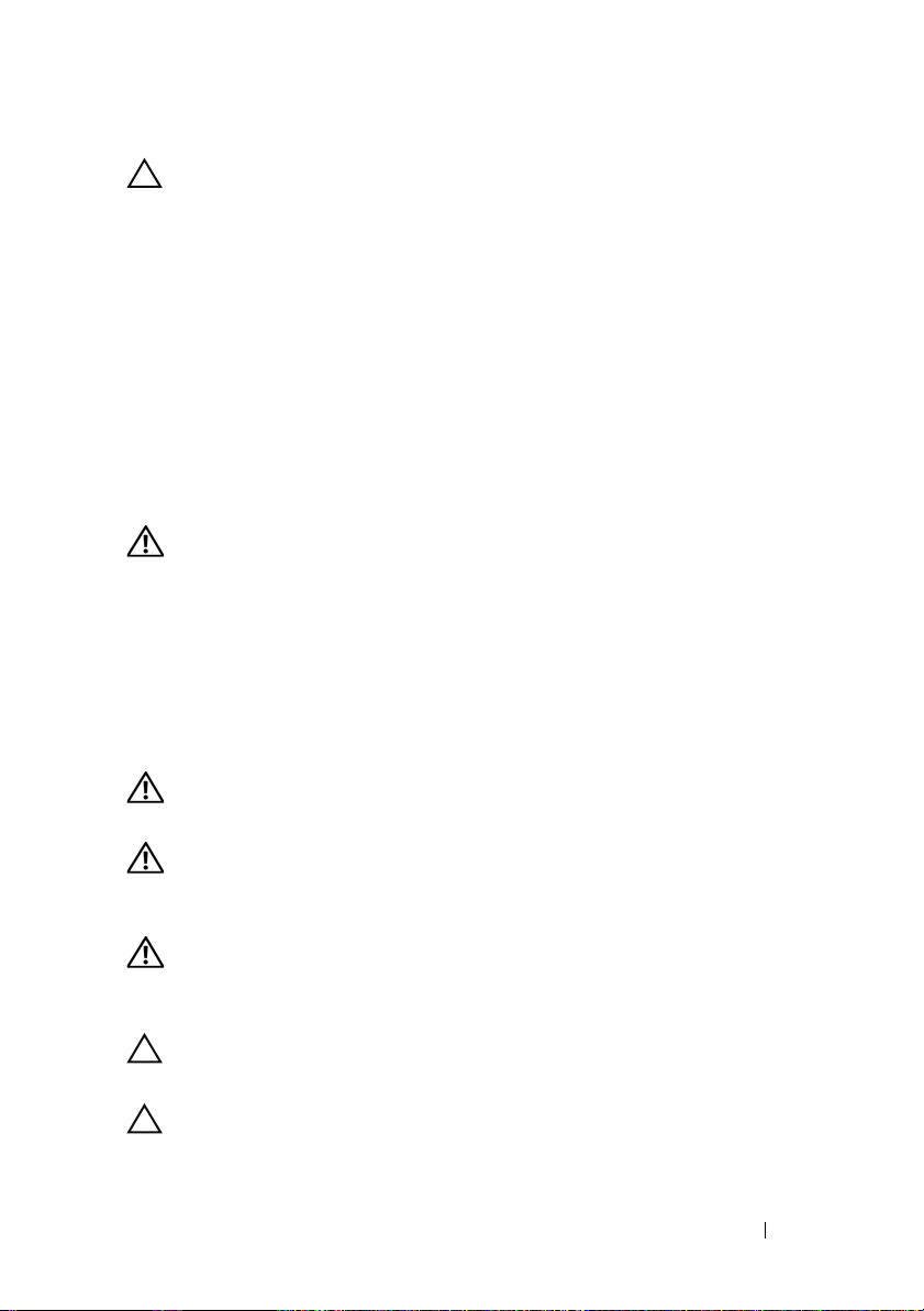
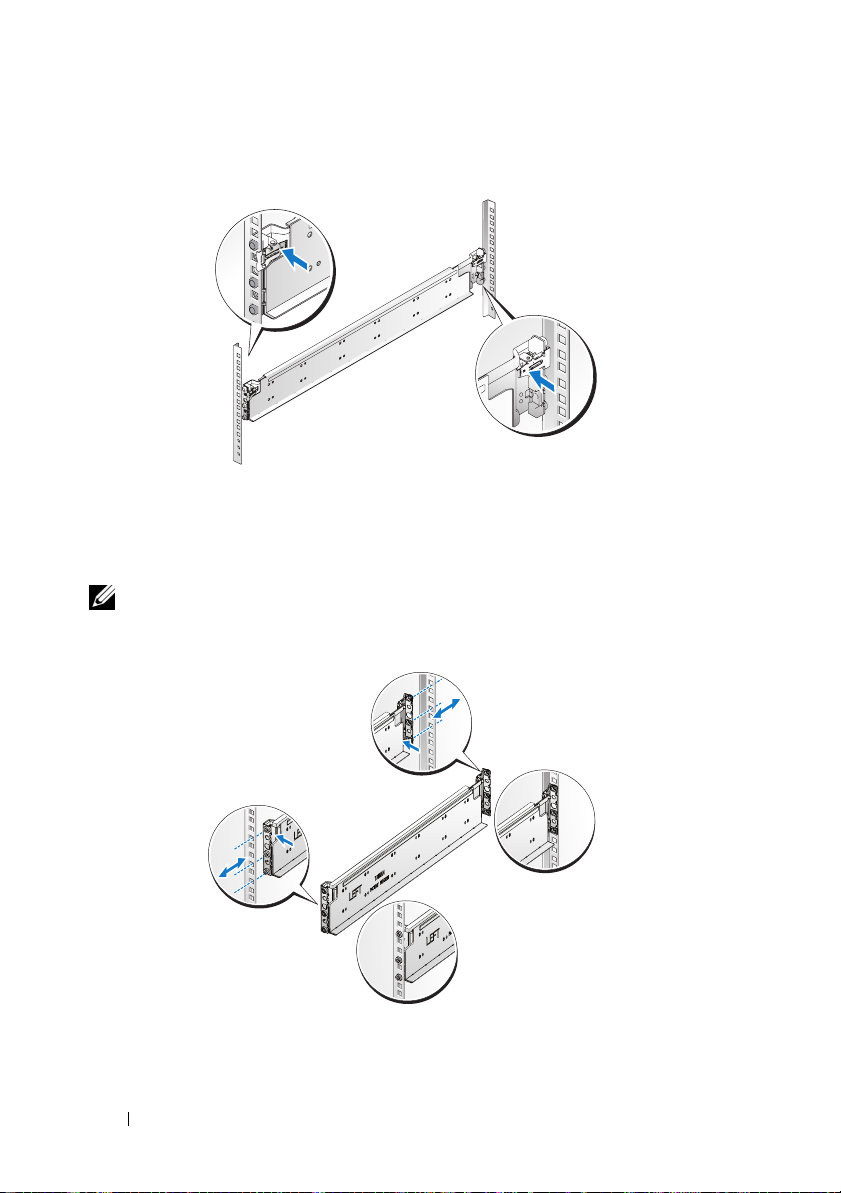
1
Pull on the latch release buttons on the end piece midpoints to open the
rail latches.
2
Align the end pieces of the rails on the vertical rack flanges to seat the pegs
in the bottom hole of the first U and the top hole of the second U. Engage
the back end of the rail until the latch locks in place.
NOTE: The rails can be used in both square-hole and round-hole racks.
Back
Front
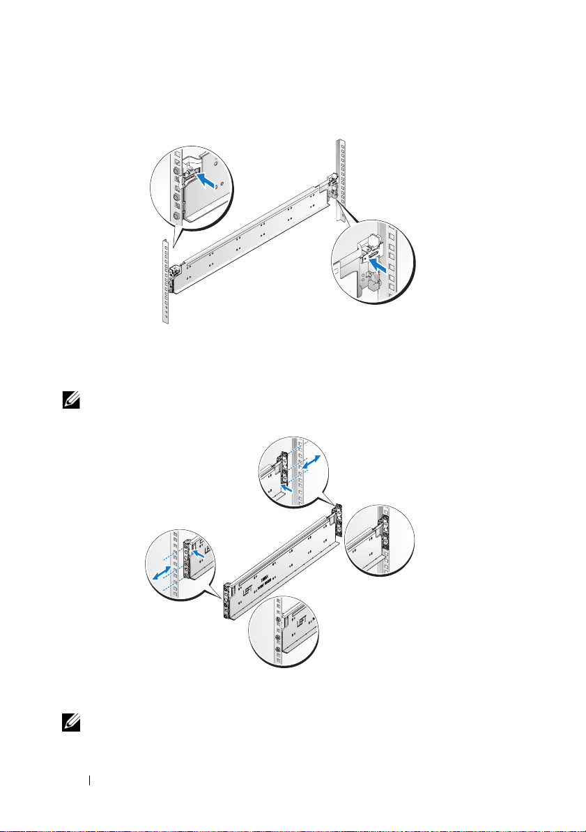
3
Repeat steps 1 to 2 to position and seat the front end piece on the vertical
flange.
NOTE: To remove the rails, pull on the latch release button on the end piece
midpoint and unseat each rail.
4 Installation and Configuration
Page 7
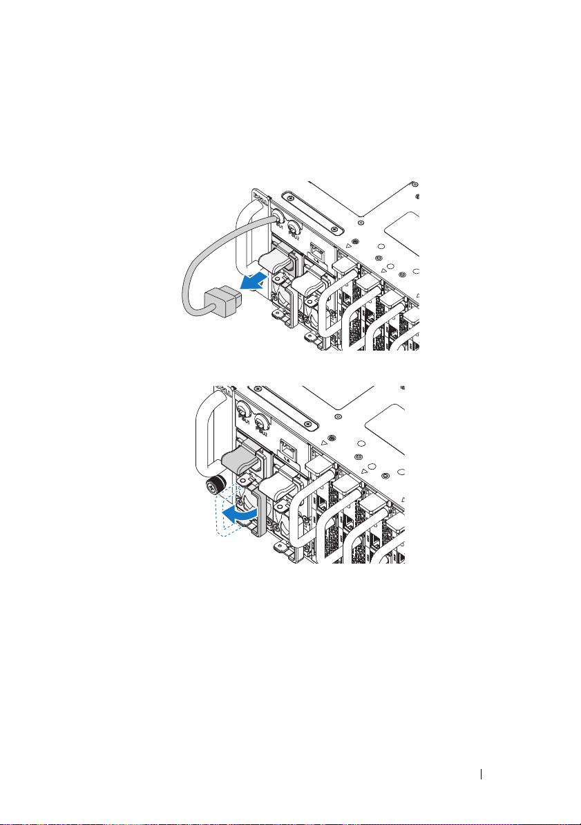
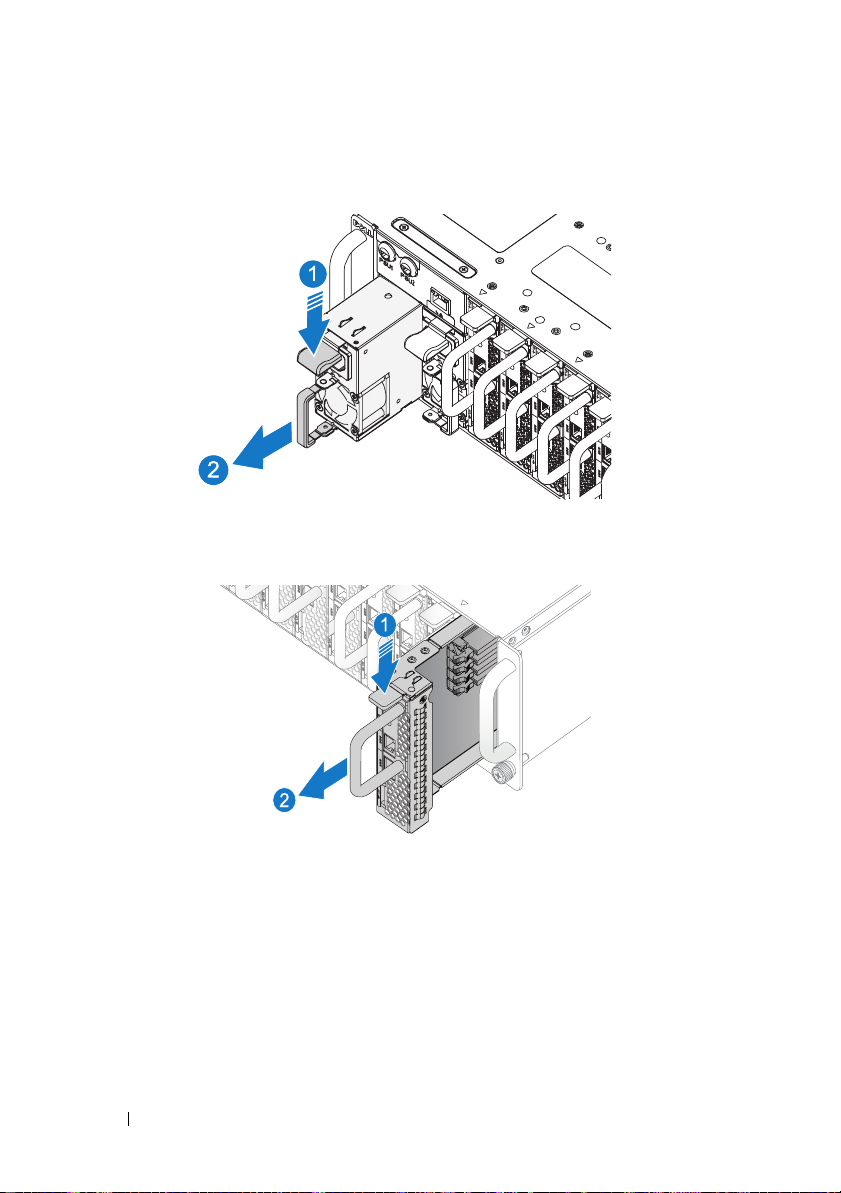
Installing the System
Empty the System Chassis
1
Unplug the power cable from the power supply unit.
.
2
Pull out the power supply unit handle.
Installation and Configuration 5
Page 8

3
Press down on the release latch .
4
Pull the power supply unit out of the system .
5
Press the release latch down .
6
Pull the sled out of the system .
6 Installation and Configuration
Page 9
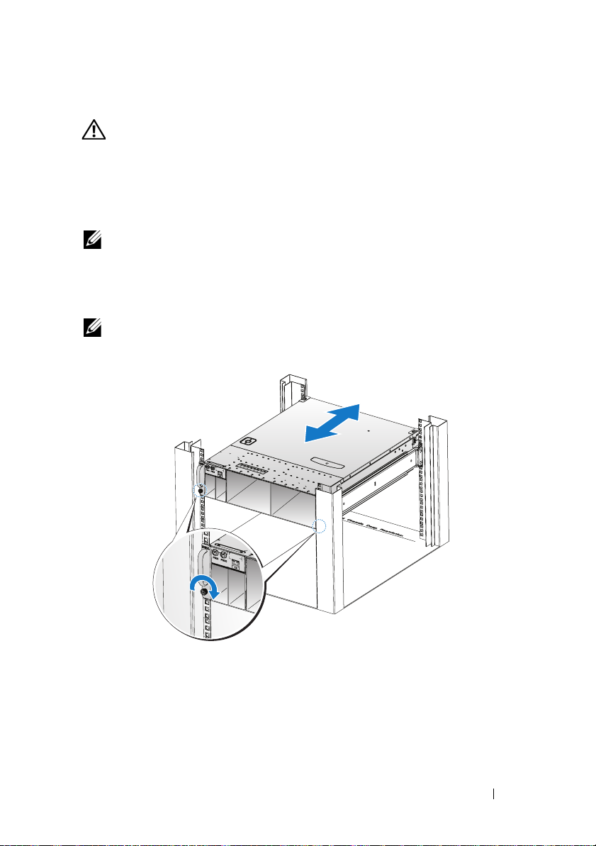
Installing the System Into the Rack
WARNING: Whenever you need to lift the system, get others to assist you.
To avoid injury, do not attempt to lift the system by yourself.
1
Slide the system into the rack.
2
If present, remove the chassis stabilizer shipping bracket (optional) from
the rack.
NOTE: To transport systems already installed in the rack, ensure that the two
chassis stabilizer shipping brackets (optional) are in place.
3
Tighten the captive thumbscrews to secure the ears of the system to the
front of the rack.
NOTE: Make sure the latch release mechanism is engaged correctly.
Installation and Configuration 7
Page 10
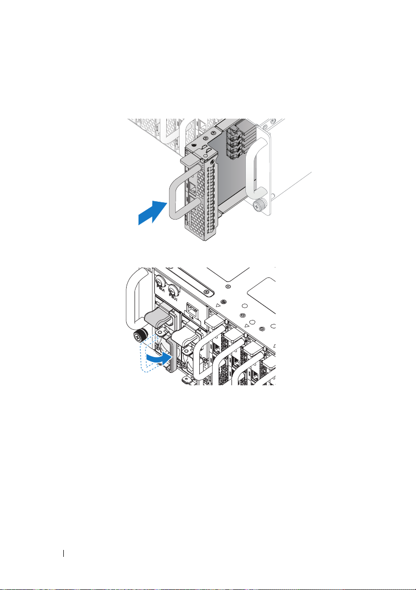
Populate the System
1
Push the power supply unit into the system until flush with the case and
the release latch locks.
2
Close the power supply unit handle.
8 Installation and Configuration
Page 11
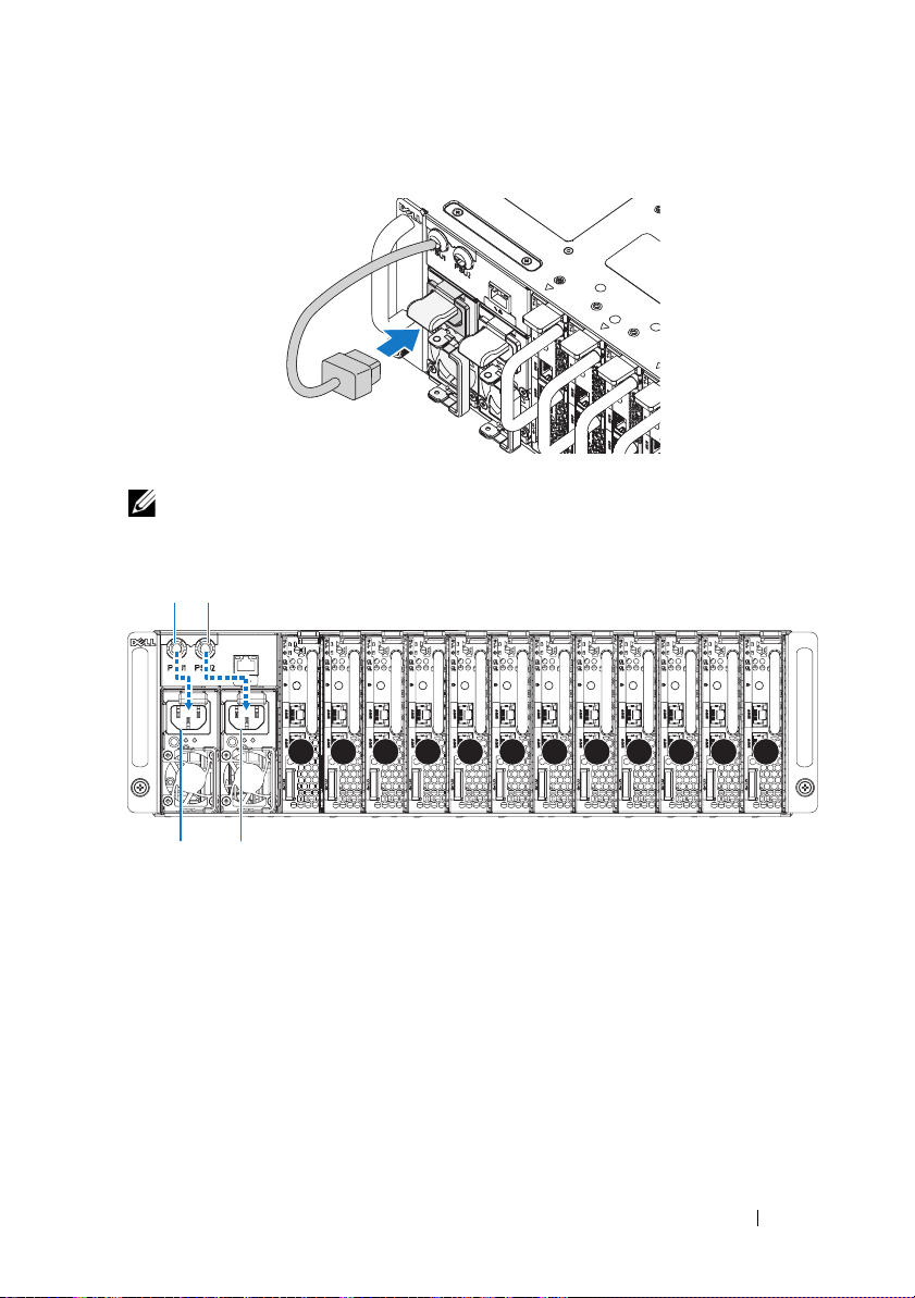
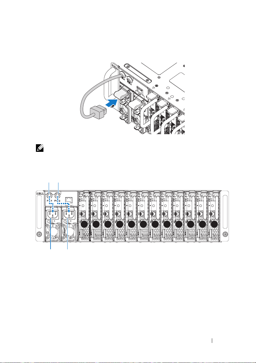
3
Plug the chassis power cable into the power supply unit.
NOTE: The correct configuration of the integral chassis AC power cables to the
PSU sockets is as shown in the following illustration.
PSU1 PSU2
1 2 3 4 5 6 7 8 9 10 11 12
PSU1 PSU2
Installation and Configuration 9
Page 12
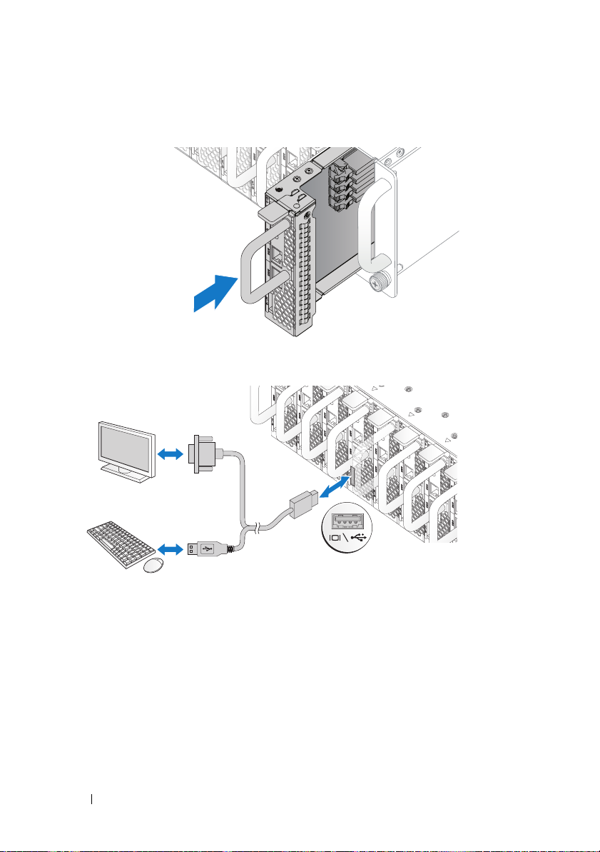
4
Push the sled into the system until flush with the case and the release latch
locks.
Connecting the Keyboard, Mouse, and Monitor
The connector on the front of your system has an icon indicating which cable
to plug in. Connect a keyboard, mouse, or monitor (optional).
10 Installation and Configuration
Page 13
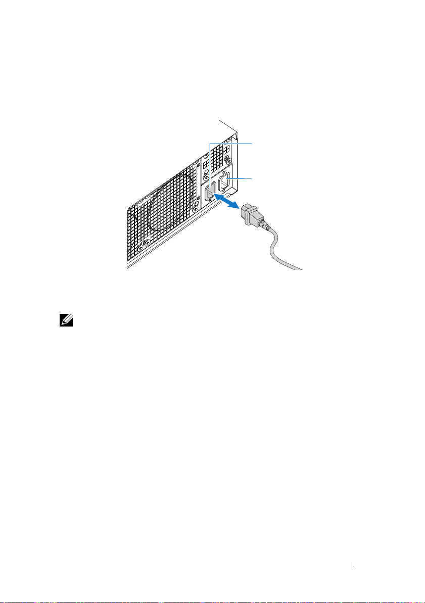
Connecting the Power Cables
1
On the back of the system, connect the mains power cable to the system’s
power socket.
AC Port 2
AC Port 1
2
Plug the other end of the power cables into a grounded electrical outlet or
a separate power source such as an uninterrupted power supply or a power
distribution unit.
NOTE:
AC Port 1 provides power to PSU1, AC Port 2 provides power to PSU2.
For more information, see step 3 of Populate the System.
Turning On the System
When connected to a power source the system automatically powers on.
See Using the Baseboard Management Controller Guide at
support.dell.com/manuals.
Installation and Configuration 11
Page 14
Complete the Operating System Setup
To install an operating system for the first time, see the installation and
configuration documentation for your operating system. Be sure the
operating system is installed before installing hardware or software not
purchased with the system.
Supported Operating Systems
• Microsoft Windows Server 2008 R2 Enterprise
• Microsoft HPC Server 2008 R2
• Microsoft Windows Server 2008 R2 Hyper-V
• Red Hat Enterprise Linux 6.0 (64-bit)
• Red Hat Enterprise 5 Update 5 (64-bit)
• SUSE Linux Enterprise Server 11 Service Pack 1 (64-bit)
• VMware ESX 4.1 Update 1
• VMware ESXi 4.1 Update 1 (Embedded option for SDHC)
• Citrix XenServer 5.6 Feature Pack 1
NOTE:
For the latest information on supported operating systems, see
support.dell.com.
Other Information You May Need
WARNING: See the safety and regulatory information that shipped with your
system. Warranty information may be included within this document or as a
separate document.
See the Hardware Owner’s Manual at support.dell.com/manuals for
information about system features, troubleshooting, and component
replacement.
See Using the Baseboard Management Controller Guide at
support.dell.com/manuals.
NOTE: Always check for updates on support.dell.com/manuals and read the
updates first because they often supersede information in other documents.
12 Installation and Configuration
Page 15

Technical Specifications
Processor (Per System Board)
Processor type Intel Xeon Processor E3-1200 product
family
Expansion Bus (Per System Board)
Bus type PCI-E x8 Gen 2
Expansion slots Mezzanine connector
Memory (Per System Board)
Architecture Dual Channel Unbuffered DDR3
1066/1333
Memory module sockets 4
Memory module capacities
Minimum RAM 2 GB
Maximum RAM 32 GB
Drives (Per System Board)
2.5" hard drives SAS 6 Gb (4 channels)
SATA 3 Gb (4 channels)
3.5" hard drives SAS 6 Gb (2 channels)
SATA 3 Gb (2 channels)
Connectors (Per System Board)
Front
NIC 10/100/1G (RJ45)
USB 2.0 (through Y-cable)
Video (DB15) (through Y-cable)
Video
Video type AST2050
Video memory 8 MB DDR2 SDRAM
2
2
1
Technical Specifications 13
Page 16

Power
AC power supply (per power supply)
Wa t ta g e
Vo lt ag e
Heat dissipation
Maximum inrush current
Physical
Height 13 cm (5.1 in)
Width 44.7 cm (17.6 in)
Depth 75 cm (29.5 in)
Weight (loaded: maximum weight) 8-sled configuration:
Weight (empty) 8-sled configuration:
1400 W
200-240 VAC, 50/60 Hz
55.67 BTU/hr max
55 A max
42.4 kg (93.48 lbs.)
12-sled configuration:
48.13 kg (106.11 lbs.)
27.4 kg (60.41 lbs.)
12-sled configuration:
32.02 kg (70.59 lbs.)
Environmental
NOTE: For additional information about environmental measurements for specific
system configurations, see dell.com/environmental_datasheets.
Temperature
Operating
10°C to 35°C (50°F to 95°F) with a
maximum temperature gradation of 10°C
(per hour)
NOTE: For altitudes above 2,950 feet, the
maximum operating temperatures derated
to 1°F/550 ft.
Storage
–40°C to 65°C (-40°F to 149°F) with a
maximum temperature gradation of 20°C
per hour
14 Technical Specifications
Page 17

Environmental (continued)
Relative Humidity
Operating
Storage
Maximum vibration
Operating
Storage
Maximum shock
Operating
Storage
Altitude
Operating
Storage
Airborne Contaminant Level
Class
20% to 80% (noncondensing) with a
maximum humidity gradation of 10%
per hour
5% to 95% (noncondensing)
0.26 Grms at 5–350 Hz
1.87 Grms at 10–500 Hz for 15 minutes
One shock pulse in the positive z axis
(one pulse on each side of the system) of
31 G for 2.6 ms in the operational
orientation
Six consecutively executed shock pulses
in the positive and negative x, y, and z
axes (one pulse on each side of the
system) of 71 G for up to 2 ms.
Six consecutively executed shock pulses
in the positive and negative x, y, and z
axes (one pulse on each side of the
system) of 22 G faired square wave pulse
with velocity change at 200 inches/second
-16 to 3,048 m (-50 to 10,000 ft.)
-16 to 10,600 m (-50 to 35,000 ft.)
G1 as defined by ISA-S71.04-1985
Technical Specifications 15
Page 18

Acoustics
Sound Power (Units: LwAd-UL,bels)
Idle in 23 ± 2°C ambient
SPEC power at 50% in 23 ± 2°C
ambient
<= 7.0
<= 7.2
NOTE: LwAd-UL is the upper limit sound power level (LwAd) calculated by ISO 9296
(1988) and measured in accordance with ISO7779 (1999).
16 Technical Specifications
Page 19

Modèle réglementaire B04S
Dell PowerEdge C5220
Guide de
mise en route
Page 20
Remarques, précautions et avertissements
REMARQUE : une REMARQUE indique des informations importantes qui peuvent
vous aider à mieux utiliser votre système.
PRÉCAUTION : une PRÉCAUTION indique un risque d'endommagement du
matériel ou de perte de données en cas de non respect des instructions.
AVERTISSEMENT: un AVERTISSEMENT indique un risque d'endommagement
du matériel, de blessures corporelles ou même de mort.
____________________
Les informations contenues dans ce document sont sujettes à modification sans préavis.
© 2011 Dell Inc. tous droits réservés.
La reproduction de ce document, de quelque manière que ce soit, sans l'autorisation écrite de Dell Inc.
est strictement interdite.
Marques utilisées dans ce document : Dell™, le logo DELL et PowerEdge™ sont des marques de
Dell Inc. Intel
d'autres pays. Microsoft
Corporation aux États-Unis et/ou dans d'autres pays. Red Hat
marques déposées de Red Hat, Inc. aux États-Unis et/ou dans d'autres pays. SUSE™ est une marque
de Novell Inc. aux États-Unis et dans d'autres pays. Citrix
déposées ou des marques de Citrix Systems, Inc. aux États-Unis et/ou dans d'autres pays. VMware
est une marque déposée ou une marque de VMware, Inc. aux États-Unis ou dans d'autres pays.
D'autres marques et noms commerciaux peuvent être utilisés dans ce document pour faire référence
aux entités revendiquant la propriété de ces marques ou de ces noms de produits. Dell Inc. rejette tout
intérêt propriétaire dans les marques et les noms commerciaux autres que les siens.
®
et Intel® Xeon® sont des marques déposées d'Intel Corporation aux États-Unis et dans
®
et Windows® sont des marques ou des marques déposées de Microsoft
®
et Red Hat Enterprise Linux® sont des
®
, Xen® et XenServer® sont des marques
®
Modèle réglementaire B04S
04-2011 N/P F8DV3 Rév. A00
Page 21
PRÉCAUTION : lieux à accès restreint
Ce serveur est conçu pour être installé uniquement dans des lieux à accès
restreint tels que définis dans Cl. 1.2.7.3 du document IEC 60950-1: 2001,
où les deux conditions suivantes s'appliquent :
• Seuls peuvent avoir accès le personnel d'entretien et les utilisateurs qui ont
été informés des motifs des restrictions appliquées au lieu et des
précautions à prendre.
• L'accès, qui se fait par l'intermédiaire d'un outil ou d'un verrou et d'une
clé, ou par d'autres moyens de sécurité, est contrôlé par le responsable en
charge du lieu.
Installation et configuration
AVERTISSEMENT: avant de commencer la procédure suivante, lisez les
consignes de sécurité fournies avec le système. Respectez ces consignes.
Déballage du système
Sortez le système de son emballage et identifiez chaque élément.
Installation sans outil des rails
AVERTISSEMENT: demandez toujours de l'aide avant de soulever le système.
N'essayez pas de le soulever seul, car vous risqueriez de vous blesser.
AVERTISSEMENT: le système n'est fixé ni au rack ni aux rails. Vous devez le
soutenir correctement au cours de l'installation et du retrait pour éviter de
l'endommager ou de vous blesser.
AVERTISSEMENT: afin d'éviter un éventuel choc électrique, assurez-vous de
disposer d'un troisième conducteur de mise à la terre pour l'installation du rack.
L'équipement du rack doit assurer un flux d'air suffisant pour bien refroidir le
système.
PRÉCAUTION : lorsque vous installez des rails dans un rack à trous carrés,
vérifiez que les taquets de fixation à tête carrée glissent bien dans les trous
carrés.
PRÉCAUTION : pour une installation correcte, les embouts carrés doivent être
alignés avec les montants du rack.
Installation et configuration 19
Page 22

1
Pour ouvrir les rails, appuyez sur les boutons d'éjection des loquets situé au
milieu des embouts.
2
Alignez les embouts des rails avec les collerettes verticales pour que les
taquets de fixation s'insèrent dans le trou du bas de la première unité en U
et le trou du haut de la deuxième unité en U. Glissez l'arrière du rail
jusqu'à enclenchement du loquet.
REMARQUE : les rails peuvent être utilisés à la fois dans des racks à trous carrés
et à trous ronds.
Back
Front
20 Installation et configuration
Page 23

3
Répétez les opérations 1 et 2 pour positionner et fixer l'embout avant sur la
collerette verticale.
REMARQUE : pour retirer les rails, appuyez sur le bouton d'éjection du loquet situé
au milieu de l'embout et dégagez les rails un par un.
Installation du système
Vider le châssis du système
1
Débranchez le câble d'alimentation du bloc d'alimentation.
.
2
Tirez la poignée du bloc d'alimentation.
Installation et configuration 21
Page 24

3
Appuyez sur le loquet d'éjection .
4
Retirez le bloc d'alimentation du système .
5
Appuyez sur le loquet d'éjection .
6
Retirez le plateau du système .
22 Installation et configuration
Page 25

Installation du système dans le rack
AVERTISSEMENT: demandez toujours de l'aide avant de soulever le système.
N'essayez pas de le soulever seul, car vous risqueriez de vous blesser.
1
Glissez le système dans le rack.
2
Si le support d'expédition du stabilisateur de châssis (en option) est
présent, retirez-le du rack.
REMARQUE : avant de transporter des systèmes déjà installés dans le rack,
assurez-vous que les deux supports d'expédition du stabilisateur de châssis
(en option) sont en place.
3
Serrez les vis à serrage à main afin de fixer les pattes du système à l'avant
du rack.
REMARQUE : assurez-vous que le mécanisme d'éjection du loquet est bien
en place.
Installation et configuration 23
Page 26

Équiper le système
1
Poussez le bloc d'alimentation dans le système jusqu'à ce qu'il soit au
même niveau que le châssis et que les verrous des loquets d'éjection.
2
Rabattez la poignée du bloc d'alimentation.
24 Installation et configuration
Page 27

3
Branchez le câble d'alimentation du châssis sur le bloc d'alimentation.
REMARQUE : la configuration correcte des câbles d'alimentation en CA sur les
connecteurs des unités d'alimentation est présentée ci-dessous.
PSU1 PSU2
1 2 3 4 5 6 7 8 9 10 11 12
PSU1 PSU2
Installation et configuration 25
Page 28

4
Poussez le plateau dans le système jusqu'à ce qu'il soit au même niveau
que le châssis et que les verrous des loquets d'éjection.
Connexion du clavier, de la souris et du moniteur
Le connecteur situé à l'avant de votre système comporte une icône indiquant
quel câble brancher. Connectez un clavier, une souris ou un moniteur
(facultatif).
26 Installation et configuration
Page 29

Connexion des câbles d'alimentation
1
À l'arrière du système, branchez le câble d'alimentation secteur au
connecteur d'alimentation du système.
AC Port 2
AC Port 1
2
Branchez ensuite l'autre extrémité des câbles d'alimentation sur une prise
de courant mise à la terre ou sur une source d'alimentation autonome
(onduleur ou unité de distribution de l'alimentation).
REMARQUE :
alimente l'unité PSU2. Pour plus d'informations, consultez l'étape 3 de la section
Équiper le système.
le port AC Port 1 alimente l'unité PSU1, tandis que le port AC Port 2
Mise sous tension du système
Lorsqu'il est connecté à une source d'alimentation, le système s'allume
automatiquement. Consultez le manuel Using the Baseboard Management
Controller Guide (Guide d'utilisation des contrôleurs de gestion de la carte
mère) à l'adresse support.dell.com/manuals.
Installation et configuration 27
Page 30

Finalisation de l'installation du système d'exploitation
Voir la documentation relative à l'installation et à la configuration du système
d'exploitation si vous installez celui-ci pour la première fois. Veillez à installer
le système d'exploitation avant tout élément matériel ou logiciel acheté
séparément.
Systèmes d'exploitation pris en charge
• Microsoft Windows Server 2008 R2 Entreprise
• Microsoft HPC Server 2008 R2
• Microsoft Windows Server 2008 R2 Hyper-V
• Red Hat Enterprise Linux 6.0 (64 bits)
• Mise à jour 5 de Red Hat Enterprise 5 (64 bits)
• Service Pack 1 de SUSE Linux Enterprise Server 11 (64 bits)
• Mise à jour 1 de VMware ESX 4.1
• Mise à jour 1 de VMware ESXi 4.1 (option Intégrée pour SDHC)
• Pack de fonctionnalités 1 de Citrix XenServer 5.6
REMARQUE : pour obtenir les informations les plus récentes sur les systèmes
d'exploitation pris en charge, rendez-vous sur le site support.dell.com.
28 Installation et configuration
Page 31

Autres informations utiles
AVERTISSEMENT:
fournies avec votre système. Les informations sur la garantie se trouvent dans ce
document ou dans un document distinct.
Pour obtenir des informations sur les fonctionnalités, le dépannage et le
remplacement des composants du système, consultez le manuel Hardware
Owner’s Manual (Manuel du propriétaire du matériel) à l'adresse
support.dell.com/manuals.
Consultez également le manuel Using the Baseboard Management Controller
Guide (Guide d'utilisation des contrôleurs de gestion de la carte mère) à
l'adresse support.dell.com/manuals.
REMARQUE : vérifiez toujours si des mises à jour sont disponibles sur le site
support.dell.com/manuals et lisez-les en premier, car elles remplacent souvent les
informations que contiennent les autres documents.
voir les informations sur la sécurité et les réglementations
Installation et configuration 29
Page 32

Caractéristiques techniques
Processeur (par carte système)
Type de processeur Famille de produits du processeur
Intel Xeon E3-1200
Bus d'extension (par carte système)
Type de bus PCI-E x8 Gen 2
Logements d'extension Connecteur de carte mezzanine
Mémoire (par carte système)
Architecture DDR3 double canal 1066/1333 sans
tampon
Connecteurs de barrettes de mémoire 4
Capacité des barrettes de mémoire
RAM minimale 2Go
RAM maximale 32 Go
Disques (par carte système)
Disques durs 2,5 pouces SAS 6 Go (4 canaux)
SATA 3 Go (4 canaux)
Disques durs 3,5 pouces SAS 6 Go (2 canaux)
SATA 3 Go (2 canaux)
Connecteurs (par carte système)
Avant
Carte réseau 10/100/1G (RJ45)
USB 2.0 (par câble en Y)
Vidéo (DB15) (par câble en Y)
Vidéo
Type de vidéo AST2050
Mémoire vidéo SDRAM DDR2 8 Mo
2
2
1
30 Caractéristiques techniques
Page 33

Alimentation
Alimentation secteur (par bloc
d'alimentation)
Puissance
Te ns i on
Dissipation thermique
Courant d'appel maximal
Caractéristiques physiques
Hauteur 13 cm (5,1 po)
Largeur 44,7 cm (17,6 po)
Profondeur 75 cm (29,5 po)
Poids (chargé : poids maximal) Configuration à 8 plateaux :
Poids (vide) Configuration à 8 plateaux :
1 400 W
200-240 VCA, 50/60 Hz
55,67 BTU/h max
55 A max
42,4 kg (93,48 lb)
Configuration à 12 plateaux :
48,13 kg (106,11 lb)
27,4 kg (60,41 lb)
Configuration à 12 plateaux :
32,02 kg (70,59 lb)
Caractéristiques techniques 31
Page 34

Environnement
REMARQUE : pour plus d'informations concernant les mesures environnementales
liées à différentes configurations spécifiques, rendez-vous sur
dell.com/environmental_datasheets.
Température
En fonctionnement
De 10 à 35 °C (de 50 à 95 °F) avec un
gradient thermique maximal de 10 °C (par
heure)
REMARQUE : pour les altitudes supérieures à
900 mètres, la température maximale de
fonctionnement est réduite de 1° C / 300 mètres.
Stockage
Humidité relative
En fonctionnement
Stockage
Tolérance maximale aux vibrations
En fonctionnement
Stockage
Choc maximal
En fonctionnement
Stockage
De -40 à 65 °C (de -40 à 149 °F) avec un
gradient thermique maximal de 20 °C
par heure
De 20 à 80 % (sans condensation) avec un
gradient d'humidité maximal de 10 %
par heure
De 5 à 95 % (sans condensation)
0,26 Grms à 5–350 Hz
1,87 Grms avec un balayage de 10 à 500 Hz
pendant 15 minutes
Une impulsion de choc de 31 G de chaque
côté du système, pendant 2,6 ms sur l'axe z
positif (système installé dans la position de
fonctionnement)
Six chocs consécutifs de 71 G pendant un
maximum de 2 ms sur les axes x, y et z en
positif et négatif (une impulsion de chaque
côté du système).
Six chocs consécutifs sur les axes x, y et z
en positif et négatif (une impulsion de
chaque côté du système) d'impulsion
d'onde carrée de 22 G avec un changement
de vitesse de 508 cm/s
32 Caractéristiques techniques
Page 35

Environnement (suite)
Altitude
En fonctionnement
Stockage
Contaminants en suspension dans l'air
Classe
Acoustique
Puissance acoustique (Unités : LwAd-UL, bels)
Inactif si température ambiante de 23
°
C
± 2
Puissance SPEC à 50 % si température
°
ambiante de 23 ± 2
C
-16 à 3 048 m (-50 à 10 000 pieds)
-16 à 10 600 m (-50 à 35 000 pieds)
G1 selon la norme ISA-S71.04-1985
<= 7.0
<= 7.2
REMARQUE : LwAd-UL représente le plafond du niveau de puissance acoustique
(LwAd). Il est calculé par ISO 9296 (1988) et mesuré conformément à la réglementation
ISO7779 (1999).
Caractéristiques techniques 33
Page 36

34 Caractéristiques techniques
Page 37

Modelo de regulamentação B04S
Dell PowerEdge C5220
Primeiros passos
com o sistema
Page 38

Notas, Avisos e Advertências
NOTA: Uma NOTA fornece informações importantes para ajudar você a usar
melhor o computador.
AVISO: Um AVISO indica um potencial de danos ao hardware ou a perda de dados
se as instruções não forem seguidas.
ADVERTÊNCIA: Uma ADVERTÊNCIA indica um potencial de danos à propriedade,
risco de lesões corporais ou mesmo risco de vida.
____________________
As informações contidas nesta publicação estão sujeitas a alterações sem aviso prévio.
© 2011 Dell Inc. Todos os direitos reservados.
Qualquer forma de reprodução deste material sem a permissão por escrito da Dell Inc. é expressamente
proibida.
Marcas comerciais usadas neste texto: Dell™, o logotipo DELL e PowerEdge™ são marcas comerciais
da Dell Inc., Intel
e em outros países. Microsoft
Corporation nos Estados Unidos e/ou em outros países. Red Hat
marcas registradas da Red Hat, Inc. nos Estados Unidos e/ou em outros países. SUSE™ é uma marca
comercial da Novell, Inc., nos Estados Unidos e em outros países. Citrix
marcas registradas ou marcas comerciais da Citrix System, Inc. nos Estados Unidos e/ou outros países.
VMware
Outras marcas e nomes comerciais podem ser usados nesta publicação como referência às entidades
que reivindicam essas marcas e nomes ou a seus produtos. A Dell Inc. renuncia ao direito de qualquer
participação em nomes e marcas comerciais que não sejam de sua propriedade.
®
e Intel® Xeon® são marcas registradas da Intel Corporation nos Estados Unidos
®
é uma marca registrada da VMWare, Inc. nos Estados Unidos ou em outros países.
®
e Windows® são marcas comerciais ou marcas registradas da Microsoft
®
e Red Hat Enterprise Linux® são
®
, Xen® e XenServer® são
Modelo de regulamentação B04S
2011-04 N/P F8DV3 Rev. A00
Page 39

AVISO: Local de acesso restrito
Este servidor destina-se a instalação apenas em locais de acesso restrito,
conforme definido na cláusula. 1.2.7.3 da IEC 60950-1: 2001, segundo a qual
as duas condições a seguir se aplicam:
• O acesso pode ser obtido apenas por profissionais de manutenção ou
usuários orientados sobre os motivos das restrições aplicadas ao local e
sobre todas as precauções que devem ser adotadas.
• O acesso deverá ser feito com o uso de uma ferramenta ou de uma trava
com chave, ou outros dispositivos de segurança, sendo controlado pela
autoridade responsável pelo local.
Instalação e configuração
ADVERTÊNCIA: Antes de executar o procedimento a seguir, leia e siga as
instruções de segurança fornecidas com o sistema.
Remover o sistema da embalagem
Remova o sistema da embalagem e identifique cada item.
Como instalar a solução de trilhos não usinados
ADVERTÊNCIA: Sempre que precisar levantar o sistema, solicite a ajuda de
outras pessoas. Para evitar ferimentos, não tente levantá-lo por conta própria.
ADVERTÊNCIA: O sistema não é preso ao rack nem montado nos trilhos. Para
evitar lesões pessoais ou danos ao sistema, apoie o rack do sistema de modo
adequado durante a instalação ou remoção.
ADVERTÊNCIA: Para evitar possíveis riscos de choque elétrico, é necessário
usar um condutor de segurança aterrado na instalação do rack. O equipamento do
rack deve fornecer ventilação suficiente para que o sistema mantenha o grau de
refrigeração adequado.
AVISO: Ao instalar os trilhos em um rack de orifício retangular é importante
garantir que o pino retangular deslize pelos orifícios retangulares.
AVISO: Os pinos retangulares devem ficar rentes ao eixo do rack para instalação
correta.
Instalação e configuração 37
Page 40

1
Puxe os botões de liberação da trava no centro da extremidade traseira para
abrir as travas do trilho.
2
Alinhe as extremidades traseiras dos trilhos nas guias verticais do rack para
instalar os pinos no orifício inferior do primeiro U e no orifício superior do
segundo U. Prenda a extremidade da parte posterior do trilho até encaixar
a trava.
NOTA: Os trilhos podem ser usados em rack de orifício retangular e redondo.
Back
Front
38 Instalação e configuração
Page 41

3
Repita as etapas 1 a 2 para posicionar e instalar a extremidade da parte
frontal na guia vertical.
NOTA: Para remover os trilhos, puxe o botão para liberar a trava no centro da
extremidade traseira e desinstale cada trilho.
Instalação do sistema
Esvazie o chassi do sistema
1
Desconecte o cabo de alimentação da unidade de fonte de alimentação.
.
2
Puxe a alça da unidade de fonte de alimentação.
Instalação e configuração 39
Page 42

3
Pressione para baixo a trava de liberação .
4
Retire a unidade de fonte de alimentação do sistema .
5
Pressione para baixo a trava de liberação .
6
Retire o componente do sistema .
40 Instalação e configuração
Page 43

Instalação do sistema sobre o rack
ADVERTÊNCIA: Sempre que precisar levantar o sistema, solicite a ajuda de
outras pessoas. Para evitar ferimentos, não tente levantá-lo por conta própria.
1
Deslize o sistema sobre o rack.
2
Se estiverem presentes, remova do rack os dois suportes de envio de
estabilização do chassi (opcionais).
NOTA: Para transportar sistemas já instalados no rack, verifique se os dois
suportes de envio de estabilização do chassi (opcionais) estão no lugar certo.
3
Enrosque os parafusos prisioneiros de aperto manual para prender as abas
do sistema ao rack.
NOTA: Verifique se o mecanismo de liberação da trava está posicionado
corretamente.
Instalação e configuração 41
Page 44

Preenchimento do sistema
1
Insira a unidade de fonte de alimentação no sistema até estar rente ao
gabinete e às travas de liberação.
2
Feche a alça da unidade de fonte de alimentação.
42 Instalação e configuração
Page 45

3
Conecte o cabo de alimentação do chassi à unidade de fonte de
alimentação.
NOTA: Veja na ilustração a seguir a configuração correta dos cabos de
alimentação CA do chassi nos soquetes de PSU (unidades de fonte de alimentação).
PSU1 PSU2
1 2 3 4 5 6 7 8 9 10 11 12
PSU1 PSU2
Instalação e configuração 43
Page 46

4
Insira o suporte deslizante no sistema até estar rente ao gabinete e às travas
de liberação.
Conexão de teclado, mouse e monitor
O conector na parte frontal do sistema tem um ícone indicando qual cabo
deve ser conectado. Conecte um teclado, mouse ou monitor (opcional).
44 Instalação e configuração
Page 47

Conexão dos cabos de alimentação
1
Na parte traseira do sistema, conecte o cabo de alimentação principal ao
soquete de alimentação do sistema.
AC Port 2
AC Port 1
2
Conecte a outra extremidade dos cabos de alimentação a uma tomada
elétrica aterrada ou a uma fonte de alimentação separada, como uma fonte
de alimentação ininterrupta ou a uma unidade de distribuição de energia.
NOTA:
A porta 1 CA fornece energia para a PSU1, a porta 2 CA fornece energia
para a PSU2. Para obter mais informações, consulte a etapa 3 do Preenchimento do
sistema.
Como ligar o sistema
Quando conectado a uma fonte de alimentação, o sistema é ligado
automaticamente. Consulte a seção Using the Baseboard Management
Controller Guide (Uso do Guia do controlador de gerenciamento da placa de
base) em support.dell.com/manuals.
Instalação e configuração 45
Page 48

Concluir a configuração do sistema operacional
Para instalar um sistema operacional pela primeira vez, consulte a
documentação de instalação e configuração do sistema operacional.
Certifique-se de que o sistema operacional esteja instalado antes de instalar
qualquer hardware ou software que não tenha sido adquirido com o sistema.
Sistemas operacionais compatíveis
• Microsoft Windows Server 2008 R2, edição Enterprise
• Microsoft HPC Server 2008 R2
• Microsoft Windows Server 2008 R2 Hyper-V
• Red Hat Enterprise Linux 6.0 (64 bits)
• Atualização 5 para Red Hat Enterprise 5 (64 bits)
• Service Pack 1 para SUSE Linux Enterprise Server 11 (64 bits)
• Atualização 1 para VMware ESX 4.1
• Atualização 1 para VMware ESX 4.1 (opção integrada para SDHC)
• Pacote de recursos 1 Citrix XenServer 5.6
NOTA:
Para obter as informações mais recentes sobre os sistemas operacionais
compatíveis, consulte o site www.support.dell.com.
Outras informações úteis
ADVERTÊNCIA: Consulte as informações de normalização e de segurança
fornecidas com o sistema. As informações de garantia podem estar incluídas neste
documento ou serem fornecidas em um documento separado.
Consulte o Manual do proprietário de hardware em support.dell.com/manuals
(em inglês) para obter mais informações sobre os recursos do sistema, solução
de problemas e substituição de componentes.
Consulte a seção Using the Baseboard Management Controller Guide (Uso do
Guia do controlador de gerenciamento da placa de base) em
support.dell.com/manuals.
NOTA: Sempre verifique se há atualizações disponíveis no site
support.dell.com/manuals (em inglês) e leia primeiro as atualizações, pois estas
geralmente substituem informações contidas em outros documentos.
46 Instalação e configuração
Page 49

Especificações técnicas
Processador (por placa de sistema)
Tipo de processador Processador Intel Xeon da família
de produtos E3-1200
Barramento de expansão (por placa de
sistema)
Tipo de barramento PCI-E x8 Gen 2
Slots de expansão Conector mezzanine
Memória (por placa de sistema)
Arquitetura DDR3 de canal duplo sem buffer
de 1066/1333
Soquetes de módulos de memória 4
Capacidades dos módulos de memória
Mínimo de RAM 2 GB
Máximo de RAM 32 GB
Unidades (por placa de sistema)
discos rígidos de 2,5" SAS de 6 Gbit (4 canais)
SATA de 3 Gbit (4 canais)
discos rígidos de 3,5" SAS de 6 Gbit (2 canais)
SATA de 3 Gbit (2 canais)
Conectores (por placa de sistema)
Frontais
NIC 10/100/1G (RJ45)
USB 2.0 (por cabo-Y)
Vídeo (DB15) (por cabo-Y)
Vídeo
Tipo de vídeo AST2050
Memória de vídeo DDR2 SDRAM de 8 MB
2
2
1
Especificações técnicas 47
Page 50

Alimentação
Fonte de alimentação CA (por fonte de
alimentação)
Potência
Te ns ã o
Dissipação de calor
Pico de corrente inicial máximo
Características físicas
Altura 13 cm
Largura 44,7 cm
Profundidade 75 cm
Peso (carregado: peso máximo) Configuração com 8 suportes deslizantes:
Peso (vazio) Configuração com 8 suportes deslizantes:
1400 W
200-240 VCA, 50/60 Hz
55.67 BTU/hr máximo
Máx. de 55 A
42,4 kg
Configuração com 12 suportes
deslizantes:
48,13 kg
27,4 kg
Configuração com 12 suportes
deslizantes:
32,02 kg
48 Especificações técnicas
Page 51

Requisitos ambientais
NOTA: Para obter informações adicionais sobre os valores dos requisitos ambientais
para configurações de sistema específicas, visite o site
dell.com/environmental_datasheets.
Temperatura
de operação
10°C a 35°C com variação máxima de
temperatura de 10°C (por hora)
NOTA: Para altitudes acima de 900 metros,
a temperatura de operação máxima é
avaliada em 1ºC/300 m.
Armazenamento
Umidade relativa
de operação
Armazenamento
Vibração máxima
de operação
Armazenamento
Choque máximo
de operação
Armazenamento
-40° C a 65° C com variação máxima
de 20° C por hora
20% a 80% (sem condensação) com
variação máxima de 10% por hora
5% a 95% (sem condensação)
0,26 g RMS a 5–350 Hz
1,87 g RMS a 10–500 Hz por 15 minutos
Um pulso de choque no eixo z positivo
(um pulso de cada lado do sistema) de
31 G por até 2,6 ms na orientação
operacional
Seis pulsos de choque consecutivos nos
eixos x, y e z positivos e negativos
(um pulso de cada lado do sistema)
de 71 G para até 2 metros.
Seis pulsos de choque consecutivos nos
eixos x, y e z positivos e negativos
(um pulso de cada lado do sistema)
de onda quadrada de 22 G com variação
de velocidade de 200 polegadas/segundo
Especificações técnicas 49
Page 52

Requisitos ambientais (continuação)
Altitude
de operação
Armazenamento
Nível de poluentes transportados pelo ar
Classe
Acústica
Potência do som (unidades: LwAd-UL, bels)
Inativo em ambiente com 23 ± 2°C
Potência SPEC a 50% em ambiente
°
com 23 ± 2
C
-16 a 3.048 m
-16 a 10.600 m
G1 conforme definido pela norma
ISA-S71.04-1985
<= 7.0
<= 7.2
NOTA: LwAd-UL é o maior limite de nível de potência de som (LwAd) calculado pela
ISO 9296 (1988) e medida de acordo com a ISO7779 (1999).
50 Especificações técnicas
Page 53

Modelo reglamentario B04S
Dell PowerEdge C5220
Procedimientos
iniciales
con el sistema
Page 54

Notas, precauciones y avisos
NOTA: Una NOTA proporciona información importante que le ayudará a utilizar
mejor el sistema.
PRECAUCIÓN: Un mensaje de PRECAUCIÓN indica la posibilidad de daños
en el hardware o la pérdida de datos si no se siguen las instrucciones.
AVISO: Un mensaje de AVISO indica el riesgo de daños materiales,
lesiones o incluso la muerte.
____________________
La información contenida en esta publicación puede modificarse sin previo aviso.
© 2011 Dell Inc. Todos los derechos reservados.
Queda estrictamente prohibida la reproducción de este material en cualquier forma sin la autorización
por escrito de Dell Inc.
Marcas comerciales utilizadas en este texto: Dell™, el logotipo de DELL y PowerEdge™ son marcas
comerciales de Dell Inc. Intel
en los Estados Unidos y en otros países. Microsoft
comerciales registradas de Microsoft Corporation en los Estados Unidos o en otros países. Red Hat
y Red Hat Enterprise Linux
Unidos o en otros países. SUSE™ es una marca comercial de Novell Inc. en los Estados Unidos y en
otros países. Citrix
de Citrix Systems, Inc. en los Estados Unidos o en otros países. VMware
marca comercial registrada de VMware, Inc. en los Estados Unidos o en otros países.
Otras marcas y otros nombres comerciales pueden utilizarse en esta publicación para hacer referencia
a las entidades que los poseen o a sus productos. Dell Inc. renuncia a cualquier interés sobre la
propiedad de marcas y nombres comerciales que no sean los suyos.
®
®
e Intel® Xeon® son marcas comerciales registradas de Intel Corporation
®
son marcas comerciales registradas de Red Hat, Inc. en los Estados
, Xen® y XenServer® son marcas comerciales o marcas comerciales registradas
®
y Windows® son marcas comerciales o marcas
®
es una marca comercial o
®
Modelo reglamentario B04S
Abril de 2011 N/P F8DV3 Rev. A00
Page 55

PRECAUCIÓN: Área de acceso restringido
Tal y como se define en la cláusula 1.2.7.3 de la IEC 60950-1: 2001, este
servidor ha sido diseñado para su instalación solamente en áreas de acceso
restringido, en donde se aplican las siguientes condiciones:
• Sólo pueden tener acceso personas de asistencia técnica o usuarios a los
que se haya informado de las razones de las restricciones que se aplican al
lugar y acerca de las precauciones que deban tenerse en cuenta.
• El acceso se realiza mediante un dispositivo o una cerradura y llave, u otros
medios de seguridad, y está controlado por la autoridad responsable de esta
área.61.
Instalación y configuración
AVISO: Antes de realizar el procedimiento siguiente, revise y siga las
instrucciones de seguridad incluidas con el sistema.
Desembalaje del sistema
Desembale el sistema e identifique cada elemento.
Instalación de la solución de rieles de montaje sin herramientas
AVISO: Siempre que necesite levantar el sistema, pida la ayuda de otros. Con el
fin de evitar lesiones, no intente mover el sistema usted solo.
AVISO: El sistema no está fijado al rack ni montado en los rieles. Para evitar
lesiones personales o daños en el sistema, debe sujetar adecuadamente el
sistema durante la instalación y la extracción.
AVISO: Para evitar que se produzca una descarga eléctrica, es necesario que
la instalación del rack cuente con un tercer conductor, de conexión a tierra.
El equipo del rack debe proporcionar el suficiente flujo de aire al sistema para
mantener una refrigeración adecuada.
PRECAUCIÓN: A la hora de instalar rieles en un rack con orificios cuadrados,
es importante comprobar que la espiga cuadrada se desliza correctamente a
través de los orificios cuadrados.
PRECAUCIÓN: Los espárragos cuadrados deben quedar al mismo nivel que los
postes del rack para que la instalación sea correcta.
Instalación y configuración 53
Page 56
1
Tire de los botones de liberación de los pestillos, en el centro de los
extremos, para abrir los pestillos de los rieles.
2
Alinee los extremos de los rieles de las pestañas verticales del rack para
insertar las espigas en el orificio inferior de la primera posición U y en el
orificio superior de la segunda posición U. Apriete el extremo posterior del
riel hasta que el pestillo se asiente en su lugar.
NOTA: Los rieles pueden utilizarse tanto en rieles con orificios cuadrados como
redondos.
Back
Front
54 Instalación y configuración
Page 57

3
Repita los pasos del 1 al 2 para colocar y asentar el extremo frontal en la
pestaña vertical.
NOTA: Para extraer los rieles, tire del botón de liberación del pestillo situado en el
punto medio del extremo y desencaje los rieles.
Instalación del sistema
Vacíe el chasis del sistema
1
Desconecte el cable de alimentación de la unidad de fuente
de alimentación.
2
Tire hacia fuera del asa de la unidad de fuente de alimentación.
Instalación y configuración 55
Page 58
3
Presione hacia abajo el pestillo de liberación .
4
Tire de la unidad de fuente de alimentación para extraerla del sistema .
5
Presione el pestillo de liberación hacia abajo .
6
Tire del módulo hacia fuera del sistema .
56 Instalación y configuración
Page 59

Instalación del sistema en el rack
AVISO: Siempre que necesite levantar el sistema, pida la ayuda de otros. Con el
fin de evitar lesiones, no intente mover el sistema usted solo.
1
Inserte el sistema en el rack.
2
Extraiga del rack el soporte de transporte para estabilización del chasis
(opcional) si está presente.
NOTA: Para transportar sistemas que ya están instalados en el rack, asegúrese de
que los dos soportes de transporte para estabilización del chasis (opcionales) se
encuentren en su lugar.
3
Apriete los tornillos mariposa cautivos para fijar las pestañas del sistema a
la parte frontal del rack.
NOTA: Asegúrese de que el mecanismo de liberación del pestillo esté colocado
correctamente.
Instalación y configuración 57
Page 60

Llenado del sistema
1
Introduzca la unidad de fuente de alimentación en el sistema hasta que
quede alineada con la carcasa y el pestillo de liberación se bloquee.
2
Cierre el asa de la unidad de fuente de alimentación.
58 Instalación y configuración
Page 61
3
Conecte el cable de alimentación del chasis a la unidad de fuente
de alimentación.
NOTA: En la ilustración siguiente se muestra la configuración correcta de los
cables de alimentación de CA integrales al chasis y los zócalos de la unidad de
fuente de alimentación (PSU).
PSU1 PSU2
PSU1 PSU2
1 2 3 4 5 6 7 8 9 10 11 12
Instalación y configuración 59
Page 62

4
Introduzca el módulo en el sistema hasta que quede alineado con la
carcasa y el pestillo de liberación se bloquee.
Conexión del teclado, el ratón y el monitor
El conector de la parte frontal del sistema tiene un icono que indica qué cable
debe conectarse. Conecte un teclado, un ratón o un monitor (opcional).
60 Instalación y configuración
Page 63

Conexión de los cables de alimentación
1
En la parte posterior del sistema, conecte el cable de alimentación
al zócalo de alimentación del sistema.
AC Port 2
AC Port 1
2
Conecte el otro extremo de los cables de alimentación a una toma eléctrica
con conexión a tierra o a otra fuente de energía, como por ejemplo un
sistema de alimentación ininterrumpida o una unidad de distribución
de alimentación.
NOTA:
El puerto de CA 1 suministra alimentación a PSU1, y el puerto de CA 2
suministra alimentación a PSU2. Para obtener más información, consulte el
paso 3 de Llenado del sistema.
Encendido del sistema
Cuando se conecta el sistema a una fuente de energía, se enciende
automáticamente. Consulte el documento Using the Baseboard Management
Controller Guide (Guía para el uso de la controladora de administración de la
placa base) en support.dell.com/manuals.
Instalación y configuración 61
Page 64

Instalación del sistema operativo
Para instalar un sistema operativo por primera vez, consulte la documentación
de instalación y configuración del sistema operativo. Asegúrese de que el
sistema operativo esté instalado antes de instalar hardware o software no
adquiridos con el sistema.
Sistemas operativos admitidos
• Microsoft Windows Server 2008 R2 Enterprise
• Microsoft HPC Server 2008 R2
• Microsoft Windows Server 2008 R2 Hyper-V
• Red Hat Enterprise Linux 6.0 (64 bits)
• Red Hat Enterprise 5 actualización 5 (64 bits)
• SUSE Linux Enterprise Server 11 Service Pack 1 (64 bits)
• VMware ESX 4.1 actualización 1
• VMware ESXi 4.1 actualización 1 (opción incorporada para SDHC)
• Citrix XenServer 5.6 Feature Pack 1
NOTA:
Para obtener la información más reciente sobre los sistemas operativos
admitidos, visite support.dell.com.
Otra información útil que puede necesitar
AVISO: Consulte la información sobre normativas y seguridad suministrada con el
sistema. La información sobre la garantía puede estar incluida en este documento
o constar en un documento aparte.
Consulte el Manual del propietario del hardware en
support.dell.com/manuals para obtener información sobre las características
del sistema, la solución de problemas y la sustitución de componentes.
Consulte el documento Using the Baseboard Management Controller Guide
(Guía para el uso de la controladora de administración de la placa base) en
support.dell.com/manuals.
NOTA: Compruebe si hay actualizaciones en support.dell.com/manuals y, si las hay,
léalas antes de proceder a la instalación, puesto que a menudo sustituyen la
información contenida en otros documentos.
62 Instalación y configuración
Page 65

Información de la NOM (sólo para México)
La información que se proporciona a continuación aparece en el dispositivo
descrito en este documento, en cumplimiento de los requisitos de la Norma
Oficial Mexicana (NOM):
Importador Dell Inc. de México, S.A. de C.V.
Paseo de la Reforma 2620 – 11° Piso
Col. Lomas Altas
11950 México, D.F.
Número de modelo B04S
Voltaje de alimentación 200-240 V CA
Frecuencia 50/60 Hz
Consumo eléctrico 9 A para cada entrada de alimentación
Especificaciones técnicas
Procesador (por placa base)
Tipo de procesador Procesador E3-1200 de la familia de
productos Intel Xeon
Bus de expansión (por placa base)
Tipo de bus PCI-E x8 Gen 2
Ranuras de expansión Conector intermedio
Memoria (por placa base)
Arquitectura DDR3 1 066/1 333 de dos canales sin
búfer
Zócalos de módulo de memoria 4
Capacidades del módulo de memoria
RAM mínima 2GB
RAM máxima 32 GB
Especificaciones técnicas 63
Page 66

Unidades (por placa base)
Unidades de disco duro de 2,5 pulgadas SAS 6 Gb (cuatro canales)
SATA 3 Gb (cuatro canales)
Unidades de disco duro de 3,5 pulgadas SAS 6 Gb (dos canales)
SATA 3 Gb (dos canales)
Conectores (por placa base)
Parte frontal
NIC 10/100/1G (RJ45)
USB 2.0 (a través de cable Y)
Vídeo (DB15) (a través de cable Y)
Vídeo
Tipo de vídeo AST2050
Memoria de vídeo SDRAM DDR2 de 8 MB
Alimentación
Fuente de alimentación de CA
(por fuente de alimentación)
Potencia
Vo lt aj e
Disipación de calor
Corriente de conexión máxima
2
2
1
1400W
200-240 V CA, 50/60 Hz
55,67 BTU/h (16,30 W) máx.
55 A máx.
64 Especificaciones técnicas
Page 67

Características físicas
Altura 13 cm
Anchura 44,7 cm
Profundidad 75 cm
Peso (cargado: peso máximo) Configuración con ocho módulos:
42,4 kg
Configuración con doce módulos:
48,13 kg
Peso (vacío) Configuración con ocho módulos:
27,4 kg
Configuración con doce módulos:
32,02 kg
Especificaciones ambientales
NOTA: Para obtener información adicional sobre medidas ambientales relativas a
configuraciones del sistema específicas, vaya a dell.com/environmental_datasheets.
Temperatura
En funcionamiento
De 10 a 35 °C con una gradación de
temperatura máxima de 10 °C (por hora)
NOTA: Para altitudes superiores a 900 m,
la temperatura máxima de funcionamiento
se reduce 1 °C cada 300 m.
En almacenamiento
Humedad relativa
En funcionamiento
En almacenamiento
De –40 a 65 °C con una gradación de
temperatura máxima de 20 °C por hora
Del 20 al 80% (sin condensación) con una
gradación de humedad máxima del 10%
por hora
Del 5 al 95% (sin condensación)
Especificaciones técnicas 65
Page 68

Especificaciones ambientales (continuación)
Vibración máxima
En funcionamiento
En almacenamiento
Impacto máximo
En funcionamiento
En almacenamiento
Altitud
En funcionamiento
En almacenamiento
Nivel de contaminación atmosférica
Clase
De –16 a 3 048 m
De –16 a 10 600 m
G1 de acuerdo con ISA-S71.04-1985
0,26 Grms a 5–350 Hz
1,87 Grms a 10-500 Hz durante
15 minutos
Un choque en el sentido positivo del eje z
(un choque en cada lado del sistema) de
31 G durante 2,6 ms en la orientación de
funcionamiento
Seis choques ejecutados consecutivamente en los ejes x, y y z positivo y
negativo (un choque en cada lado del
sistema) de 71 G durante un máximo
de 2 ms.
Seis choques ejecutados consecutivamente en los ejes x, y y z positivo y
negativo (un choque en cada lado del
sistema) de onda cuadrada alisada de
22 G con cambio de velocidad a 508 cm/s
66 Especificaciones técnicas
Page 69

Acústica
Potencia acústica (unidades: LwAd-UL, belios)
Inactivo en ambientes de 23 ± 2°C
Potencia SPEC al 50% en ambientes de
°
C
23 ± 2
<= 7,0
<= 7,2
NOTA: LwAd-UL es el nivel máximo de potencia acústica (LwAd) calculado según la
norma ISO9296 (1988) y medido de acuerdo con la norma ISO7779 (1999).
Especificaciones técnicas 67
Page 70

68 Especificaciones técnicas
 Loading...