

Page 1

Dell PowerEdge C5220
Getting Started
With Your System
Začínáme se systémem
Guide de mise en route
Erste Schritte mit dem System
Τα πρώτα βήµατα µε το σύστηµά σας
Rozpoczęcie pracy z systemem
Начало работы с системой
Procedimientos iniciales con el sistema
Sisteminizi Kullanmaya Başlarken
תכרעמה םע הדובעה תליחת
Page 2

Page 3

With Your System
Regulatory Model B04S
Dell PowerEdge C5220
Getting Started
Page 4
Notes, Cautions, and Warnings
NOTE: A NOTE indicates important information that helps you make better use
of your system.
CAUTION: A CAUTION indicates potential damage to hardware or loss of data
if instructions are not followed.
WARNING: A WARNING indicates a potential for property damage, personal
injury, or death.
____________________
Information in this publication is subject to change without notice.
© 2011 Dell Inc. All rights reserved.
Reproduction of these materials in any manner whatsoever without the written permission of Dell Inc.
is strictly forbidden.
Trademarks used in this text: Dell™, the DELL logo, and PowerEdge™ are trademarks of Dell Inc.
®
and Intel® Xeon® are registered trademarks of Intel Corporation in the U.S. and other countries.
Intel
Microsoft
in the United States and/or other countries. Red Hat
trademarks of Red Hat, Inc. in the United States and/or other countries. SUSE™ is a trademark of
Novell Inc. in the United States and other countries. Citrix
registered trademarks or trademarks of Citrix Systems, Inc. in the United States and/or other countries.
VMware
countries.
Other trademarks and trade names may be used in this publication to refer to either the entities claiming
the marks and names or their products. Dell Inc. disclaims any proprietary interest in trademarks and
trade names other than its own.
®
and Windows® are either trademarks or registered trademarks of Microsoft Corporation
®
is a registered trademarks or trademarks of VMWare, Inc. in the United States or other
®
and Red Hat Enterprise Linux® are registered
®
, Xen®, and XenServer® are either
Regulatory Model B04S
2011-04 P/N 505MT Rev. A00
Page 5

CAUTION: Restricted Access Location
This server is intended for installation only in restricted access locations as
defined in Cl. 1.2.7.3 of IEC 60950-1: 2001 where both these conditions
apply:
• Access can only be gained by service persons or by users who have been
instructed about the reasons for the restrictions applied to the location and
about any precautions that shall be taken.
• Access is through the use of a tool or lock and key, or other means of
security, and is controlled by the authority responsible for the location.
Installation and Configuration
WARNING: Before performing the following procedure, review and follow the
safety instructions that came with the system.
Unpacking the System
Unpack your system and identify each item.
Installing the Tool-Less Rail Solution
WARNING: Whenever you need to lift the system, get others to assist you. To
avoid injury, do not attempt to lift the system by yourself.
WARNING: The system is not fixed to the rack or mounted on the rails. To avoid
personal injury or damage to the system, you must adequately support the system
during installation and removal.
WARNING: To avoid a potential electrical shock hazard, a third wire safety
grounding conductor is necessary for the rack installation. The rack equipment
must provide sufficient airflow to the system to maintain proper cooling.
CAUTION: When installing rails in a square-hole rack it is important to ensure
that the square peg slides through the square holes.
CAUTION: Square studs must be flush with the rack posts to install properly.
Installation and Configuration 3
Page 6

1
Pull on the latch release buttons on the end piece midpoints to open the
rail latches.
2
Align the end pieces of the rails on the vertical rack flanges to seat the pegs
in the bottom hole of the first U and the top hole of the second U. Engage
the back end of the rail until the latch locks in place.
NOTE: The rails can be used in both square-hole and round-hole racks.
Back
Front
3
Repeat steps 1 to 2 to position and seat the front end piece on the vertical
flange.
NOTE: To remove the rails, pull on the latch release button on the end piece
midpoint and unseat each rail.
4 Installation and Configuration
Page 7

Installing the System
Empty the System Chassis
1
Unplug the power cable from the power supply unit.
.
2
Pull out the power supply unit handle.
Installation and Configuration 5
Page 8

3
Press down on the release latch .
4
Pull the power supply unit out of the system .
5
Press the release latch down .
6
Pull the sled out of the system .
6 Installation and Configuration
Page 9
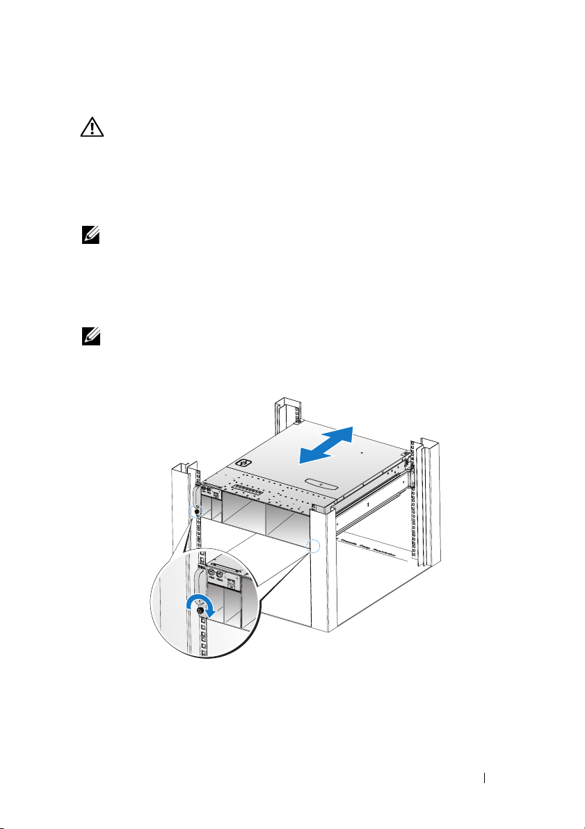
Installing the System Into the Rack
WARNING: Whenever you need to lift the system, get others to assist you.
To avoid injury, do not attempt to lift the system by yourself.
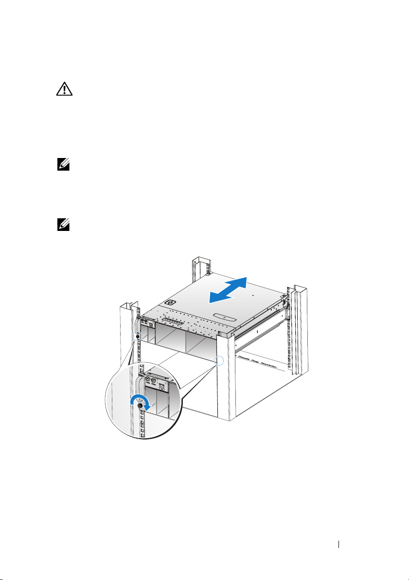
1
Slide the system into the rack.
2
If present, remove the chassis stabilizer shipping bracket (optional) from
the rack.
NOTE: To transport systems already installed in the rack, ensure that the two
chassis stabilizer shipping brackets (optional) are in place.
3
Tighten the captive thumbscrews to secure the ears of the system to the
front of the rack.
NOTE: Make sure the latch release mechanism is engaged correctly.
Installation and Configuration 7
Page 10
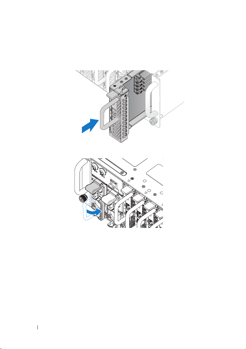
Populate the System
1
Push the power supply unit into the system until flush with the case and
the release latch locks.
2
Close the power supply unit handle.
8 Installation and Configuration
Page 11

3
Plug the chassis power cable into the power supply unit.
NOTE: The correct configuration of the integral chassis AC power cables to the
PSU sockets is as shown in the following illustration.
PSU1 PSU2
1 2 3 4 5 6 7 8 9 10 11 12
PSU1 PSU2
Installation and Configuration 9
Page 12

4
Push the sled into the system until flush with the case and the release latch
locks.
Connecting the Keyboard, Mouse, and Monitor
The connector on the front of your system has an icon indicating which cable
to plug in. Connect a keyboard, mouse, or monitor (optional).
10 Installation and Configuration
Page 13

Connecting the Power Cables
1
On the back of the system, connect the mains power cable to the system’s
power socket.
AC Port 2
AC Port 1
2
Plug the other end of the power cables into a grounded electrical outlet or
a separate power source such as an uninterrupted power supply or a power
distribution unit.
NOTE:
AC Port 1 provides power to PSU1, AC Port 2 provides power to PSU2.
For more information, see step 3 of Populate the System.
Turning On the System
When connected to a power source the system automatically powers on.
See Using the Baseboard Management Controller Guide at
support.dell.com/manuals.
Installation and Configuration 11
Page 14

Complete the Operating System Setup
To install an operating system for the first time, see the installation and
configuration documentation for your operating system. Be sure the
operating system is installed before installing hardware or software not
purchased with the system.
Supported Operating Systems
• Microsoft Windows Server 2008 R2 Enterprise
• Microsoft HPC Server 2008 R2
• Microsoft Windows Server 2008 R2 Hyper-V
• Red Hat Enterprise Linux 6.0 (64-bit)
• Red Hat Enterprise 5 Update 5 (64-bit)
• SUSE Linux Enterprise Server 11 Service Pack 1 (64-bit)
• VMware ESX 4.1 Update 1
• VMware ESXi 4.1 Update 1 (Embedded option for SDHC)
• Citrix XenServer 5.6 Feature Pack 1
NOTE:
For the latest information on supported operating systems, see
support.dell.com.
Other Information You May Need
WARNING: See the safety and regulatory information that shipped with your
system. Warranty information may be included within this document or as a
separate document.
See the Hardware Owner’s Manual at support.dell.com/manuals for
information about system features, troubleshooting, and component
replacement.
See Using the Baseboard Management Controller Guide at
support.dell.com/manuals.
NOTE: Always check for updates on support.dell.com/manuals and read the
updates first because they often supersede information in other documents.
12 Installation and Configuration
Page 15

Technical Specifications
Processor (Per System Board)
Processor type Intel Xeon Processor E3-1200 product
family
Expansion Bus (Per System Board)
Bus type PCI-E x8 Gen 2
Expansion slots Mezzanine connector
Memory (Per System Board)
Architecture Dual Channel Unbuffered DDR3
1066/1333
Memory module sockets 4
Memory module capacities
Minimum RAM 2 GB
Maximum RAM 32 GB
Drives (Per System Board)
2.5" hard drives SAS 6 Gb (4 channels)
SATA 3 Gb (4 channels)
3.5" hard drives SAS 6 Gb (2 channels)
SATA 3 Gb (2 channels)
Connectors (Per System Board)
Front
NIC 10/100/1G (RJ45)
USB 2.0 (through Y-cable)
Video (DB15) (through Y-cable)
Video
Video type AST2050
Video memory 8 MB DDR2 SDRAM
2
2
1
Technical Specifications 13
Page 16

Power
AC power supply (per power supply)
Wa t ta g e
Vo lt ag e
Heat dissipation
Maximum inrush current
Physical
Height 13 cm (5.1 in)
Width 44.7 cm (17.6 in)
Depth 75 cm (29.5 in)
Weight (loaded: maximum weight) 8-sled configuration:
Weight (empty) 8-sled configuration:
1400 W
200-240 VAC, 50/60 Hz
55.67 BTU/hr max
55 A max
42.4 kg (93.48 lbs.)
12-sled configuration:
48.13 kg (106.11 lbs.)
27.4 kg (60.41 lbs.)
12-sled configuration:
32.02 kg (70.59 lbs.)
Environmental
NOTE: For additional information about environmental measurements for specific
system configurations, see dell.com/environmental_datasheets.
Temperature
Operating
10°C to 35°C (50°F to 95°F) with a
maximum temperature gradation of 10°C
(per hour)
NOTE: For altitudes above 2,950 feet, the
maximum operating temperatures derated
to 1°F/550 ft.
Storage
–40°C to 65°C (-40°F to 149°F) with a
maximum temperature gradation of 20°C
per hour
14 Technical Specifications
Page 17

Environmental (continued)
Relative Humidity
Operating
Storage
Maximum vibration
Operating
Storage
Maximum shock
Operating
Storage
Altitude
Operating
Storage
Airborne Contaminant Level
Class
20% to 80% (noncondensing) with a
maximum humidity gradation of 10%
per hour
5% to 95% (noncondensing)
0.26 Grms at 5–350 Hz
1.87 Grms at 10–500 Hz for 15 minutes
One shock pulse in the positive z axis
(one pulse on each side of the system) of
31 G for 2.6 ms in the operational
orientation
Six consecutively executed shock pulses
in the positive and negative x, y, and z
axes (one pulse on each side of the
system) of 71 G for up to 2 ms.
Six consecutively executed shock pulses
in the positive and negative x, y, and z
axes (one pulse on each side of the
system) of 22 G faired square wave pulse
with velocity change at 200 inches/second
-16 to 3,048 m (-50 to 10,000 ft.)
-16 to 10,600 m (-50 to 35,000 ft.)
G1 as defined by ISA-S71.04-1985
Technical Specifications 15
Page 18

Acoustics
Sound Power (Units: LwAd-UL,bels)
Idle in 23 ± 2°C ambient
SPEC power at 50% in 23 ± 2°C
ambient
<= 7.0
<= 7.2
NOTE: LwAd-UL is the upper limit sound power level (LwAd) calculated by ISO 9296
(1988) and measured in accordance with ISO7779 (1999).
16 Technical Specifications
Page 19

Regulatorní model B04S
Dell PowerEdge C5220
Začínáme
se systémem
Page 20

Poznámky a upozornění
POZNÁMKA: POZNÁMKA označuje důležité informace, které pomáhají
lepšímu využití systému.
UPOZORNĚNÍ: UPOZORNĚNÍ označuje nebezpečí poškození
hardwaru nebo ztráty dat v případě nedodržení pokynů.
VAROVÁNÍ: VAROVÁNÍ upozorňuje na potenciální nebezpečí
poškození majetku, úrazu nebo smrti.
____________________
Informace v této publikaci se mohou bez předchozího upozornění změnit.
© 2011 Dell Inc. Všechna práva vyhrazena.
Jakákoli reprodukce těchto materiálů bez písemného povolení společnosti Dell Inc. je přísně zakázána.
Ochranné známky použité v tomto textu: Dell™, logo DELL a PowerEdge™ jsou ochranné známky
společnosti Dell Inc. Intel
Corporation v USA a dalších zemích. Microsoft
registrované ochranné známky společnosti Microsoft Corporation v USA a dalších zemích. Red Hat
a Red Hat Enterprise Linux
dalších zemích. SUSE™ je ochranná známka společnosti Novell Inc. v USA a dalších zemích. Citrix
®
Xen
a XenServer® jsou registrované ochranné známky nebo ochranné známky společnosti Citrix
Systems, Inc. v USA a dalších zemích. VMware
VMware, Inc. v USA a dalších zemích.
V této publikaci mohou být použity další ochranné známky a obchodní názvy s odkazem na společnosti
vlastnící tyto známky a názvy nebo na jejich produkty. Společnost Dell Inc. nemá vlastnické zájmy
vůči ochranným známkám a obchodním názvům jiným než svým vlastním.
®
a Intel® Xeon® jsou registrované ochranné známky společnosti Intel
®
jsou registrované ochranné známky společnosti Red Hat, Inc. v USA a
®
a Windows® jsou ochranné známky nebo
®
je registrovaná ochranná známka společnosti
®
®
,
Regulatorní model B04S
Duben 2011 Č. dílu 505MT Rev. A00
Page 21
UPOZORNĚNÍ: Umístění s omezeným přístupem
Tento server je určen k instalaci pouze na místa s omezeným přístupem, jak jsou
definována v čl. 1.2.7.3 normy IEC 60950-1: 2001, kde platí obě tyto podmínky:
•
Přístup mohou získat pouze servisní pracovníci nebo uživatelé, kteří byli
poučeni o důvodech omezení platného pro umístění a o veškerých
bezpečnostních opatřeních, jež je nutné dodržovat.
•
Přístup je poskytován za použití nástroje nebo zámku a klíče nebo je jinak
zabezpečen a je řízen představitelem zodpovědným za toto umístění.
Instalace a konfigurace
VAROVÁNÍ: Před provedením následujícího postupu si prostudujte
bezpečnostní pokyny dodané se systémem a řiďte se jimi.
Rozbalení systému
Rozbalte systém a identifikujte jeho jednotlivé součásti.
Instalace stojanového řešení s přístupem bez nářadí
VAROVÁNÍ: Při každém zvedání systému požádejte o asistenci.
Systém nezvedejte sami, vyvarujete se tak možného zranění.
VAROVÁNÍ: Systém není připevněn ke stojanu ani ke kolejničkám.
Chcete-li předejít možnosti zranění osob nebo poškození systému,
je třeba systém během instalace a vyjímání dostatečně stabilizovat.
VAROVÁNÍ: Chcete-li předejít nebezpečí úrazu elektrickým proudem,
je nutné při instalaci do stojanu použít třetí bezpečnostní zemnicí
vodič. Stojanové vybavení musí systému poskytovat dostatečný
průchod vzduchu a zajišt’ovat tak dostatečné chlazení.
UPOZORNĚNÍ: Při instalaci kolejniček do stojanu se čtvercovými
otvory je důležité zajistit, aby byl do čtvercových otvorů zasunut
čtyřhranný kolík.
UPOZORNĚNÍ: Pro správnou instalaci je nutné, aby byly čtyřhranné
kolíky zarovnány s otvory na stojanu.
Instalace a konfigurace 19
Page 22

1
Otevřete západky kolejniček zatažením za uvolňovací knoflíky ve středu
zadních konců kolejniček.
2
Zarovnejte koncovky kolejniček se svislými přírubami stojanu a usaďte
kolíky do dolního otvoru prvního tvaru U a do horního otvoru druhého
tvaru U. Usaďte zadní konec kolejničky tak, aby západka zaklapla na místo.
POZNÁMKA: Kolejničky lze použít ve stojanech se čtvercovými i kulatými
otvory.
Back
Front
20 Instalace a konfigurace
Page 23

3
Zopakováním kroků 1 až 2 usaďte a připevněte ke svislé přírubě přední
konec kolejničky.
POZNÁMKA: Chcete-li kolejničky vyjmout, můžete je uvolnit zatažením za
uvolňovací knoflík ve středu zadního konce kolejničky.
Instalace systému
Vyprázdnění šasi systému
1
Odpojte napájecí kabel od jednotky zdroje napájení.
.
2
Vytáhněte rukojet’ jednotky zdroje napájení.
Instalace a konfigurace 21
Page 24

3
Zatlačte uvolňovací západku směrem dolů .
4
Vytáhněte jednotku zdroje napájení ze systému .
5
Zatlačte uvolňovací západku směrem dolů .
6
Vytáhněte sáňky ze systému .
22 Instalace a konfigurace
Page 25
Instalace systému do stojanu
VAROVÁNÍ: Při každém zvedání systému požádejte o asistenci.
Systém nezvedejte sami, vyvarujete se tak možného zranění.
1
Zasuňte systém do stojanu.
2
Pokud je namontován stabilizační přepravní držák šasi (volitelný), vyjměte
jej ze stojanu.
POZNÁMKA: Chcete-li přepravovat systémy již nainstalované ve stojanu,
zajistěte, aby byly tyto dva stabilizační přepravní držáky šasi (volitelné)
správně namontovány.
3
Pomocí šroubků s roznýtovaným koncem upevněte ouška na systému k
přední části stojanu.
POZNÁMKA: Dbejte na to, aby byl správně usazen uvolňovací
mechanismus západky.
Instalace a konfigurace 23
Page 26

Zaplnění systému
1
Zasuňte jednotku zdroje napájení do systému, dokud nebude zarovnána s šasi
a nezaklapne uvolňovací západka.
2
Zavřete rukojet’ jednotky zdroje napájení.
24 Instalace a konfigurace
Page 27

3
Zapojte napájecí kabel šasi do jednotky zdroje napájení.
POZNÁMKA: Správná konfigurace integrálních napájecích kabelů šasi a
soketů PSU je znázorněna na následující ilustraci.
PSU1 PSU2
1 2 3 4 5 6 7 8 9 10 11 12
PSU1 PSU2
Instalace a konfigurace 25
Page 28

4
Zasuňte sáňky do systému, dokud nebudou zarovnány s šasi a nezaklapne
uvolňovací západka.
Připojení klávesnice, myši a monitoru
Konektor na přední straně systému je označen ikonou znázorňující, jaký kabel lze
zapojit. Připojte klávesnici, myš nebo monitor (volitelné).
26 Instalace a konfigurace
Page 29

Připojení napájecích kabelů
1
Na zadní straně systému připojte hlavní napájecí kabely do soketů napájení
systému.
AC Port 2
AC Port 1
2
Poté zasuňte druhý konec napájecích kabelů do uzemněné elektrické zásuvky
nebo je připojte k samostatnému zdroji napájení, například ke zdroji
nepřerušitelného napájení (UPS) nebo jednotce rozvaděče (PDU).
POZNÁMKA: Port AC 1 poskytuje napájení soketu PSU1, port AC 2
poskytuje napájení soketu PSU2. Další informace najdete v kroku 3 v části
Zaplnění systému.
Zapnutí systému
Po připojení ke zdroji napájení se systém zapne automaticky. Další informace
najdete v
na adrese
Průvodci použitím ovladače BMC (Baseboard Management Controller)
support.dell.com/manuals
.
Instalace a konfigurace 27
Page 30

Dokončení nastavení operačního systému
Chcete-li provést první instalaci operačního systému, postupujte podle
dokumentace k instalaci a konfiguraci operačního systému. Než začnete s instalací
hardwaru či softwaru, který nebyl zakoupen společně se systémem, ujistěte se,
že je nainstalován operační systém.
Podporované operační systémy
•
Microsoft Windows Server 2008 R2 Enterprise
•
Microsoft HPC Server 2008 R2
•
Microsoft Windows Server 2008 R2 Hyper-V
•
Red Hat Enterprise Linux 6.0 (64bitový)
•
Red Hat Enterprise 5, aktualizace 5 (64bitový)
•
SUSE Linux Enterprise Server 11 Service Pack 1 (64bitový)
•
VMware ESX 4.1, aktualizace 1
•
VMware ESXi 4.1, aktualizace 1 (integrovaná edice pro SDHC)
•
Citrix XenServer 5.6 Feature Pack 1
POZNÁMKA: Nejnovější informace o podporovaných operačních
systémech naleznete na webu support.dell.com.
Další užitečné informace
VAROVÁNÍ: Prostudujte si informace o bezpečnosti a předpisech,
které byly dodány se systémem. Informace o záruce jsou součástí
tohoto dokumentu nebo jsou přiloženy samostatně.
V
Příručce majitele hardwaru
informace o funkcích systému, řešení potíží a výměnách součástí.
Další informace najdete v
Management Controller)
POZNÁMKA: Vždy nejprve zkontrolujte a pročtěte aktualizace uvedené
na adrese support.dell.com/manuals, protože tyto aktualizace často
nahrazují informace v ostatních dokumentech.
28 Instalace a konfigurace
na adrese
Průvodci použitím ovladače BMC (Baseboard
na adrese
support.dell.com/manuals
support.dell.com/manuals
.
najdete
Page 31

Technické specifikace
Procesor (na každou základní
desku)
Typ procesoru Procesor řady Intel Xeon E3-1200
Rozšiřovací sběrnice (na každou
základní desku)
Typ sběrnice PCI-E x8, 2. generace
Rozšiřovací sloty Konektor pro rozšiřovací kartu
Pamět’ (na každou základní desku)
Architektura Dvoukanálové moduly DDR3 s taktovací
frekvencí 1066/1333 MHz, bez vyrovnávací
paměti
Sloty pro pamět’ové moduly 4
Kapacity pamět’ových modulů
Minimum paměti RAM 2 GB
Maximum paměti RAM 32 GB
Jednotky (na každou základní
desku)
2,5palcové pevné disky SAS 6 Gb (4 kanály)
SATA 3 Gb (4 kanály)
3,5palcové pevné disky SAS 6 Gb (2 kanály)
SATA 3 Gb (2 kanály)
Konektory (na každou základní
desku)
Vpředu
Sít’ 10/100/1000 Mb/s (RJ45) 2
USB 2.0 (prostřednictvím rozdvojky) 2
Video (DB15) (prostřednictvím
rozdvojky)
1
Technické specifikace 29
Page 32

Video
Typ grafiky AST2050
Grafická pamět’ 8 MB DDR2 SDRAM
Napájení
Střídavý proud (na jeden napájecí zdroj)
Výkon 1400 W
Napětí 200–240 V stř., 50/60 Hz
Odvod tepla Maximálně 55,67 BTU/hod.
Maximální nárazový proud 55 A
Rozměry
Výška 13 cm
Šířka 44,7 cm
Hloubka 75 cm
Hmotnost (maximální při zaplnění) Konfigurace s 8 sáňkami:
42,4 kg
Konfigurace s 12 sáňkami:
48,13 kg
Hmotnost (prázdné) Konfigurace s 8 sáňkami:
27,4 kg
Konfigurace s 12 sáňkami:
32,02 kg
30 Technické specifikace
Page 33

Prostředí
POZNÁMKA: Další informace o měřených údajích prostředí najdete pro
jednotlivé systémové konfigurace na adrese
dell.com/environmental_datasheets.
Teplota
Provozní 10 až 35 °C s maximálním nárůstem teploty
o 10 °C za hodinu
POZNÁMKA: V nadmořských
výškách nad 900 metrů je maximální
provozní teplota snížena o 1 °C na
každých 300 metrů.
Skladovací -40 až 65 °C s maximálním nárůstem teploty
o 20 °C za hodinu
Relativní vlhkost
Provozní 20 až 80 % (bez kondenzace) s maximálním
nárůstem vlhkosti o 10 % za hodinu
Skladovací 5 až 95 % (bez kondenzace)
Maximální vibrace
Provozní 0,26 g při 5–350 Hz
Skladovací 1,87 g při 10–500 Hz po dobu 15 minut
Maximální ráz
Provozní Jeden rázový impuls v kladné ose z (jeden
impuls na každé straně systému) o síle 31 G
v délce do 2,6 ms v provozní orientaci
Skladovací Šest po sobě jdoucích rázových impulsů v
kladné i záporné ose x, y a z (jeden impuls
na každé straně systému) o síle 71 G v délce
do 2 ms
Šest po sobě jdoucích rázových impulsů v
kladné i záporné ose x, y a z (jeden impuls
na každé straně systému) o síle 22 G pro
impuls s průběhem sladěné obdélníkové
vlny se změnou rychlosti 5,08 m/s
Technické specifikace 31
Page 34

Prostředí (pokračování)
Nadmořská výška
Provozní -16 až 3 048 m
Skladovací -16 až 10 600 m
Úroveň znečištění vzduchu
Třída G1 dle normy ISA-S71.04-1985
Akustika
Akustický výkon (jednotky: LwAd-UL, dB)
Při nečinnosti při teplotě 23 ± 2
Při 50% výkonu dle standardu SPEC při
teplotě 23 ± 2
°
C
°
C<= 70
<= 72
POZNÁMKA: LwAd-UL je úroveň horního limitu akustického výkonu (LwAd)
počítaná dle normy ISO 9296 (1988) a měřená v souladu s normou ISO 7779
(1999).
32 Technické specifikace
Page 35

Modèle réglementaire B04S
Dell PowerEdge C5220
Guide de
mise en route
Page 36

Remarques, précautions et avertissements
REMARQUE : une REMARQUE indique des informations importantes qui peuvent
vous aider à mieux utiliser votre système.
PRÉCAUTION : une PRÉCAUTION indique un risque d'endommagement du
matériel ou de perte de données en cas de non respect des instructions.
AVERTISSEMENT: un AVERTISSEMENT indique un risque d'endommagement
du matériel, de blessures corporelles ou même de mort.
____________________
Les informations contenues dans ce document sont sujettes à modification sans préavis.
© 2011 Dell Inc. tous droits réservés.
La reproduction de ce document, de quelque manière que ce soit, sans l'autorisation écrite de Dell Inc.
est strictement interdite.
Marques utilisées dans ce document : Dell™, le logo DELL et PowerEdge™ sont des marques de
Dell Inc. Intel
d'autres pays. Microsoft
Corporation aux États-Unis et/ou dans d'autres pays. Red Hat
marques déposées de Red Hat, Inc. aux États-Unis et/ou dans d'autres pays. SUSE™ est une marque
de Novell Inc. aux États-Unis et dans d'autres pays. Citrix
déposées ou des marques de Citrix Systems, Inc. aux États-Unis et/ou dans d'autres pays. VMware
est une marque déposée ou une marque de VMware, Inc. aux États-Unis ou dans d'autres pays.
D'autres marques et noms commerciaux peuvent être utilisés dans ce document pour faire référence
aux entités revendiquant la propriété de ces marques ou de ces noms de produits. Dell Inc. rejette tout
intérêt propriétaire dans les marques et les noms commerciaux autres que les siens.
®
et Intel® Xeon® sont des marques déposées d'Intel Corporation aux États-Unis et dans
®
et Windows® sont des marques ou des marques déposées de Microsoft
®
et Red Hat Enterprise Linux® sont des
®
, Xen® et XenServer® sont des marques
®
Modèle réglementaire B04S
04-2011 N/P 505MT Rév. A00
Page 37

PRÉCAUTION : lieux à accès restreint
Ce serveur est conçu pour être installé uniquement dans des lieux à accès
restreint tels que définis dans Cl. 1.2.7.3 du document IEC 60950-1: 2001,
où les deux conditions suivantes s'appliquent :
• Seuls peuvent avoir accès le personnel d'entretien et les utilisateurs qui ont
été informés des motifs des restrictions appliquées au lieu et des
précautions à prendre.
• L'accès, qui se fait par l'intermédiaire d'un outil ou d'un verrou et d'une
clé, ou par d'autres moyens de sécurité, est contrôlé par le responsable en
charge du lieu.
Installation et configuration
AVERTISSEMENT: avant de commencer la procédure suivante, lisez les
consignes de sécurité fournies avec le système. Respectez ces consignes.
Déballage du système
Sortez le système de son emballage et identifiez chaque élément.
Installation sans outil des rails
AVERTISSEMENT: demandez toujours de l'aide avant de soulever le système.
N'essayez pas de le soulever seul, car vous risqueriez de vous blesser.
AVERTISSEMENT: le système n'est fixé ni au rack ni aux rails. Vous devez le
soutenir correctement au cours de l'installation et du retrait pour éviter de
l'endommager ou de vous blesser.
AVERTISSEMENT: afin d'éviter un éventuel choc électrique, assurez-vous de
disposer d'un troisième conducteur de mise à la terre pour l'installation du rack.
L'équipement du rack doit assurer un flux d'air suffisant pour bien refroidir le
système.
PRÉCAUTION : lorsque vous installez des rails dans un rack à trous carrés,
vérifiez que les taquets de fixation à tête carrée glissent bien dans les trous
carrés.
PRÉCAUTION : pour une installation correcte, les embouts carrés doivent être
alignés avec les montants du rack.
Installation et configuration 35
Page 38

1
Pour ouvrir les rails, appuyez sur les boutons d'éjection des loquets situé au
milieu des embouts.
2
Alignez les embouts des rails avec les collerettes verticales pour que les
taquets de fixation s'insèrent dans le trou du bas de la première unité en U
et le trou du haut de la deuxième unité en U. Glissez l'arrière du rail
jusqu'à enclenchement du loquet.
REMARQUE : les rails peuvent être utilisés à la fois dans des racks à trous carrés
et à trous ronds.
Back
Front
36 Installation et configuration
Page 39

3
Répétez les opérations 1 et 2 pour positionner et fixer l'embout avant sur la
collerette verticale.
REMARQUE : pour retirer les rails, appuyez sur le bouton d'éjection du loquet situé
au milieu de l'embout et dégagez les rails un par un.
Installation du système
Vider le châssis du système
1
Débranchez le câble d'alimentation du bloc d'alimentation.
.
2
Tirez la poignée du bloc d'alimentation.
Installation et configuration 37
Page 40

3
Appuyez sur le loquet d'éjection .
4
Retirez le bloc d'alimentation du système .
5
Appuyez sur le loquet d'éjection .
6
Retirez le plateau du système .
38 Installation et configuration
Page 41

Installation du système dans le rack
AVERTISSEMENT: demandez toujours de l'aide avant de soulever le système.
N'essayez pas de le soulever seul, car vous risqueriez de vous blesser.
1
Glissez le système dans le rack.
2
Si le support d'expédition du stabilisateur de châssis (en option) est
présent, retirez-le du rack.
REMARQUE : avant de transporter des systèmes déjà installés dans le rack,
assurez-vous que les deux supports d'expédition du stabilisateur de châssis
(en option) sont en place.
3
Serrez les vis à serrage à main afin de fixer les pattes du système à l'avant
du rack.
REMARQUE : assurez-vous que le mécanisme d'éjection du loquet est bien
en place.
Installation et configuration 39
Page 42

Équiper le système
1
Poussez le bloc d'alimentation dans le système jusqu'à ce qu'il soit au
même niveau que le châssis et que les verrous des loquets d'éjection.
2
Rabattez la poignée du bloc d'alimentation.
40 Installation et configuration
Page 43

3
Branchez le câble d'alimentation du châssis sur le bloc d'alimentation.
REMARQUE : la configuration correcte des câbles d'alimentation en CA sur les
connecteurs des unités d'alimentation est présentée ci-dessous.
PSU1 PSU2
1 2 3 4 5 6 7 8 9 10 11 12
PSU1 PSU2
Installation et configuration 41
Page 44

4
Poussez le plateau dans le système jusqu'à ce qu'il soit au même niveau
que le châssis et que les verrous des loquets d'éjection.
Connexion du clavier, de la souris et du moniteur
Le connecteur situé à l'avant de votre système comporte une icône indiquant
quel câble brancher. Connectez un clavier, une souris ou un moniteur
(facultatif).
42 Installation et configuration
Page 45

Connexion des câbles d'alimentation
1
À l'arrière du système, branchez le câble d'alimentation secteur au
connecteur d'alimentation du système.
AC Port 2
AC Port 1
2
Branchez ensuite l'autre extrémité des câbles d'alimentation sur une prise
de courant mise à la terre ou sur une source d'alimentation autonome
(onduleur ou unité de distribution de l'alimentation).
REMARQUE :
alimente l'unité PSU2. Pour plus d'informations, consultez l'étape 3 de la section
Équiper le système.
le port AC Port 1 alimente l'unité PSU1, tandis que le port AC Port 2
Mise sous tension du système
Lorsqu'il est connecté à une source d'alimentation, le système s'allume
automatiquement. Consultez le manuel Using the Baseboard Management
Controller Guide (Guide d'utilisation des contrôleurs de gestion de la carte
mère) à l'adresse support.dell.com/manuals.
Installation et configuration 43
Page 46

Finalisation de l'installation du système d'exploitation
Voir la documentation relative à l'installation et à la configuration du système
d'exploitation si vous installez celui-ci pour la première fois. Veillez à installer
le système d'exploitation avant tout élément matériel ou logiciel acheté
séparément.
Systèmes d'exploitation pris en charge
• Microsoft Windows Server 2008 R2 Entreprise
• Microsoft HPC Server 2008 R2
• Microsoft Windows Server 2008 R2 Hyper-V
• Red Hat Enterprise Linux 6.0 (64 bits)
• Mise à jour 5 de Red Hat Enterprise 5 (64 bits)
• Service Pack 1 de SUSE Linux Enterprise Server 11 (64 bits)
• Mise à jour 1 de VMware ESX 4.1
• Mise à jour 1 de VMware ESXi 4.1 (option Intégrée pour SDHC)
• Pack de fonctionnalités 1 de Citrix XenServer 5.6
REMARQUE : pour obtenir les informations les plus récentes sur les systèmes
d'exploitation pris en charge, rendez-vous sur le site support.dell.com.
44 Installation et configuration
Page 47

Autres informations utiles
AVERTISSEMENT:
fournies avec votre système. Les informations sur la garantie se trouvent dans ce
document ou dans un document distinct.
Pour obtenir des informations sur les fonctionnalités, le dépannage et le
remplacement des composants du système, consultez le manuel Hardware
Owner’s Manual (Manuel du propriétaire du matériel) à l'adresse
support.dell.com/manuals.
Consultez également le manuel Using the Baseboard Management Controller
Guide (Guide d'utilisation des contrôleurs de gestion de la carte mère) à
l'adresse support.dell.com/manuals.
REMARQUE : vérifiez toujours si des mises à jour sont disponibles sur le site
support.dell.com/manuals et lisez-les en premier, car elles remplacent souvent les
informations que contiennent les autres documents.
voir les informations sur la sécurité et les réglementations
Installation et configuration 45
Page 48

Caractéristiques techniques
Processeur (par carte système)
Type de processeur Famille de produits du processeur
Intel Xeon E3-1200
Bus d'extension (par carte système)
Type de bus PCI-E x8 Gen 2
Logements d'extension Connecteur de carte mezzanine
Mémoire (par carte système)
Architecture DDR3 double canal 1066/1333 sans
tampon
Connecteurs de barrettes de mémoire 4
Capacité des barrettes de mémoire
RAM minimale 2Go
RAM maximale 32 Go
Disques (par carte système)
Disques durs 2,5 pouces SAS 6 Go (4 canaux)
SATA 3 Go (4 canaux)
Disques durs 3,5 pouces SAS 6 Go (2 canaux)
SATA 3 Go (2 canaux)
Connecteurs (par carte système)
Avant
Carte réseau 10/100/1G (RJ45)
USB 2.0 (par câble en Y)
Vidéo (DB15) (par câble en Y)
Vidéo
Type de vidéo AST2050
Mémoire vidéo SDRAM DDR2 8 Mo
2
2
1
46 Caractéristiques techniques
Page 49

Alimentation
Alimentation secteur (par bloc
d'alimentation)
Puissance
Te ns i on
Dissipation thermique
Courant d'appel maximal
Caractéristiques physiques
Hauteur 13 cm (5,1 po)
Largeur 44,7 cm (17,6 po)
Profondeur 75 cm (29,5 po)
Poids (chargé : poids maximal) Configuration à 8 plateaux :
Poids (vide) Configuration à 8 plateaux :
1 400 W
200-240 VCA, 50/60 Hz
55,67 BTU/h max
55 A max
42,4 kg (93,48 lb)
Configuration à 12 plateaux :
48,13 kg (106,11 lb)
27,4 kg (60,41 lb)
Configuration à 12 plateaux :
32,02 kg (70,59 lb)
Caractéristiques techniques 47
Page 50

Environnement
REMARQUE : pour plus d'informations concernant les mesures environnementales
liées à différentes configurations spécifiques, rendez-vous sur
dell.com/environmental_datasheets.
Température
En fonctionnement
De 10 à 35 °C (de 50 à 95 °F) avec un
gradient thermique maximal de 10 °C (par
heure)
REMARQUE : pour les altitudes supérieures à
900 mètres, la température maximale de
fonctionnement est réduite de 1° C / 300 mètres.
Stockage
Humidité relative
En fonctionnement
Stockage
Tolérance maximale aux vibrations
En fonctionnement
Stockage
Choc maximal
En fonctionnement
Stockage
De -40 à 65 °C (de -40 à 149 °F) avec un
gradient thermique maximal de 20 °C
par heure
De 20 à 80 % (sans condensation) avec un
gradient d'humidité maximal de 10 %
par heure
De 5 à 95 % (sans condensation)
0,26 Grms à 5–350 Hz
1,87 Grms avec un balayage de 10 à 500 Hz
pendant 15 minutes
Une impulsion de choc de 31 G de chaque
côté du système, pendant 2,6 ms sur l'axe z
positif (système installé dans la position de
fonctionnement)
Six chocs consécutifs de 71 G pendant un
maximum de 2 ms sur les axes x, y et z en
positif et négatif (une impulsion de chaque
côté du système).
Six chocs consécutifs sur les axes x, y et z
en positif et négatif (une impulsion de
chaque côté du système) d'impulsion
d'onde carrée de 22 G avec un changement
de vitesse de 508 cm/s
48 Caractéristiques techniques
Page 51

Environnement (suite)
Altitude
En fonctionnement
Stockage
Contaminants en suspension dans l'air
Classe
Acoustique
Puissance acoustique (Unités : LwAd-UL, bels)
Inactif si température ambiante de 23
°
C
± 2
Puissance SPEC à 50 % si température
°
ambiante de 23 ± 2
C
-16 à 3 048 m (-50 à 10 000 pieds)
-16 à 10 600 m (-50 à 35 000 pieds)
G1 selon la norme ISA-S71.04-1985
<= 7.0
<= 7.2
REMARQUE : LwAd-UL représente le plafond du niveau de puissance acoustique
(LwAd). Il est calculé par ISO 9296 (1988) et mesuré conformément à la réglementation
ISO7779 (1999).
Caractéristiques techniques 49
Page 52

50 Caractéristiques techniques
Page 53

Modell B04S
Dell PowerEdge C5220
Erste Schritte
mit dem System
Page 54

Anmerkungen, Vorsichtshinweise und
Warnungen
ANMERKUNG: Eine ANMERKUNG enthält wichtige Informationen, mit deren Hilfe
Sie Ihr System besser nutzen können.
VORSICHTSHINWEIS: Ein VORSICHTSHINWEIS macht darauf aufmerksam,
dass eine Beschädigung der Hardware oder Verlust von Daten droht,
wenn Anweisungen nicht befolgt werden.
WARNUNG: Eine WARNUNG weist auf Gefahrenquellen hin, die materielle
Schäden, Verletzungen oder sogar den Tod von Personen zur Folge haben können.
____________________
Irrtümer und technische Änderungen vorbehalten.
© 2011 Dell Inc. Alle Rechte vorbehalten.
Jegliche Reproduktion dieser Materialien ist ohne vorherige schriftliche Genehmigung von Dell Inc.
strengstens untersagt.
Marken in diesem Text: Dell™, das DELL Logo und PowerEdge™ sind Marken von Dell Inc. Intel
®
und Intel
Microsoft
USA und/oder anderen Ländern. Red Hat
von Red Hat, Inc. in den USA und/oder anderen Ländern. SUSE™ ist eine Marke von Novell, Inc. in
den USA und anderen Ländern. Citrix
Marken von Citrix Systems, Inc. in den USA und/oder anderen Ländern. VMware
eingetragene Marke von VMware, Inc. in den USA oder anderen Ländern.
Alle anderen in dieser Publikation möglicherweise verwendete Marken und Handelsbezeichnungen
beziehen sich entweder auf die entsprechenden Hersteller und Firmen oder auf deren Produkte.
Dell Inc. erhebt keinen Anspruch auf Markenzeichen und Handelsbezeichnungen mit Ausnahme
der eigenen.
Xeon® sind eingetragene Marken der Intel Corporation in den USA und anderen Ländern.
®
und Windows® sind Marken oder eingetragene Marken der Microsoft Corporation in den
®
und Red Hat Enterprise Linux® sind eingetragene Marken
®
, Xen® und XenServer® sind eingetragene Marken oder
®
ist eine
®
Modell B04S
April 2011 Teilenr. 505MT Rev. A00
Page 55

VORSICHTSHINWEIS: Standort mit Zugangsbeschränkung
Dieser Server ist ausschließlich für eine Installation in Standorten mit
eingeschränktem Zugriff vorgesehen, wie es in Cl. 1.2.7.3 von
IEC 60950-1: 2001 definiert wurde, wo diese beiden Bedingungen gelten:
• Zugang dürfen nur Servicemitarbeiter oder Benutzer erhalten, die über die
Gründe für die Einschränkungen hinsichtlich des Standorts und über alle
notwendigen Vorsichtsmaßnahmen unterrichtet sind.
• Der Zugang erfolgt durch die Nutzung eines Werkzeugs, einer Sperre,
eines Schlüssels oder anderer Sicherungsvorrichtungen und wird durch
die für den Standort zuständige Dienststelle kontrolliert.
Installation und Konfiguration
WARNUNG: Lesen und befolgen Sie vor dem Ausführen der folgenden Schritte die
Sicherheitshinweise für das System.
Auspacken des Systems
Entnehmen Sie das System der Verpackung und identifizieren Sie die
einzelnen Komponenten.
Installation der Schienenvorrichtung (ohne Werkzeug)
WARNUNG: Beim Anheben des Systems sollten Sie sich stets von anderen helfen
lassen. Um Verletzungen zu vermeiden, sollten Sie nicht versuchen, das System
allein zu bewegen.
WARNUNG: Das System ist nicht am Rack oder an den Schienen befestigt. Um
Verletzungen und Schäden am System zu vermeiden, müssen Sie das System beim
Installieren und Entfernen ausreichend unterstützen.
WARNUNG: Um die Gefahr eines elektrischen Schlags zu vermeiden, wird für die
Rack-Installation ein Schutzerdungsleiter (dritter Anschlussdraht) benötigt. Die
Rack-Ausrüstung muss genügend Luftbewegung um das System ermöglichen,
damit eine ausreichende Kühlung gewährleistet ist.
VORSICHTSHINWEIS: Beim Installieren von Schienen in einem Rack mit
Vierkantlöchern muss darauf geachtet werden, dass die Vierkantzapfen in die
Löcher eingreifen.
VORSICHTSHINWEIS: Für eine ordnungsgemäße Installation müssen die
Vierkantbolzen bündig mit den Rackstützen abschließen.
Installation und Konfiguration 53
Page 56

1
Ziehen Sie an den Verriegelungsklinken mitten auf den Endstücken,
um die Schienenverriegelungen zu öffnen.
2
Richten Sie die Endstücke der Schienen so an den vertikalen
Rackflanschen aus, dass die Zapfen in das untere Loch der ersten
Befestigungseinheit und das obere Loch der zweiten Befestigungseinheit
eingreifen. Befestigen Sie das hintere Ende der Schiene, bis die Sperrklinke
einrastet.
ANMERKUNG: Die Schienen lassen sich sowohl in Racks mit Vierkant- als auch
mit Rundlöchern verwenden.
Back
Front
54 Installation und Konfiguration
Page 57

3
Wiederholen Sie die Schritte 1 bis 2, um das vordere Endstück am
vertikalen Flansch zu positionieren und zu befestigen.
ANMERKUNG: Um die Schienen zu entfernen, ziehen Sie an der
Verriegelungsklinke mitten auf dem Endstück und lösen Sie die einzelnen Schienen.
Installation des Systems
Entleeren des Systemgehäuses
1
Ziehen Sie das Netzstromkabel vom Netzteil ab.
.
2
Ziehen Sie den Netzteilgriff heraus.
Installation und Konfiguration 55
Page 58

3
Drücken Sie auf die Sperrklinke .
4
Ziehen Sie das Netzteil aus dem System .
5
Drücken Sie die Sperrklinke nach unten .
6
Ziehen Sie den Schacht aus dem System .
56 Installation und Konfiguration
Page 59

Installation des Systems im Rack
WARNUNG: Beim Anheben des Systems sollten Sie sich stets von anderen helfen
lassen. Um Verletzungen zu vermeiden, sollten Sie nicht versuchen, das System
allein zu bewegen.
1
Schieben Sie das System in das Rack.
2
Entfernen Sie gegebenenfalls die Sicherungsklammer zur Gehäusestabilisierung (optional) vom Rack.
ANMERKUNG: Wenn Sie bereits im Rack installierte Systeme transportieren,
stellen Sie sicher, dass die zwei Sicherungsklammern zur Gehäusestabilisierung
(optional) angebracht sind.
3
Ziehen Sie die selbstsichernden Flügelschrauben fest, um das System mit
den Seiten vorn am Rack zu sichern.
ANMERKUNG: Vergewissern Sie sich, dass der Verriegelungsmechanismus
richtig eingerastet ist.
Installation und Konfiguration 57
Page 60

Bestücken des Systems
1
Schieben Sie das Netzteil in das System, bis es bündig mit dem Gehäuse
und den Verriegelungen der Freigabehebel abschließt.
2
Schließen Sie den Netzteilgriff.
58 Installation und Konfiguration
Page 61

3
Stecken Sie das Gehäusenetzkabel in das Netzteil.
ANMERKUNG: Die folgende Abbildung zeigt die richtige Konfiguration der
eingebauten Gehäusenetzkabel zu den Steckdosen des Netzteils.
PSU1 PSU2
1 2 3 4 5 6 7 8 9 10 11 12
PSU1 PSU2
Installation und Konfiguration 59
Page 62

4
Schieben Sie den Schacht in das System, bis er bündig mit dem Gehäuse
und den Verriegelungen der Freigabehebel abschließt.
Anschließen von Tastatur, Maus und Bildschirm
Der Anschluss an der Vorderseite des Systems ist mit einem Symbol
gekennzeichnet, das angibt, welches Kabel einzustecken ist. Schließen Sie
eine Tastatur, eine Maus oder einen Bildschirm an (optional).
60 Installation und Konfiguration
Page 63

Anschließen der Netzstromkabel
1
Verbinden Sie das Netzstromkabel mit der Steckdose auf der Rückseite
des Systems.
AC Port 2
AC Port 1
2
Verbinden Sie das andere Ende des Netzstromkabels mit einer geerdeten
Steckdose oder einer separaten Spannungsquelle, etwa einer
unterbrechungsfreien Stromversorgung oder einem Stromverteiler.
ANMERKUNG:
der AC-Port 2 versorgt das zweite Netzteil (PSU2). Weitere Informationen finden Sie
in Schritt 3 unter „Bestücken des Systems“.
Der AC-Port 1 versorgt das erste Netzteil (PSU1) mit Strom,
Einschalten des Systems
Wenn das System an eine Stromquelle angeschlossen ist, wird es automatisch
eingeschaltet. Weitere Hinweise finden Sie im Using the Baseboard
Management Controller Guide (Handbuch für die Verwendung des
Baseboard-Management-Controllers) unter support.dell.com/manuals.
Installation und Konfiguration 61
Page 64

Abschließen des Betriebssystem-Setups
Wenn Sie das Betriebssystem erstmals installieren, finden Sie weitere
Hinweise in der Dokumentation zur Installation und Konfiguration des
Betriebssystems. Das Betriebssystem muss installiert sein, bevor Sie andere,
nicht zusammen mit dem System erworbene Hardware oder Software
installieren.
Unterstützte Betriebssysteme
• Microsoft Windows Server 2008 R2 Enterprise
• Microsoft HPC Server 2008 R2
• Microsoft Windows Server 2008 R2 Hyper-V
• Red Hat Enterprise Linux 6.0 (64-Bit)
• Red Hat Enterprise 5 Update 5 (64-Bit)
• SUSE Linux Enterprise Server 11 Service Pack 1 (64-Bit)
• VMware ESX 4.1 Update 1
• VMware ESXi 4.1 Update 1 (integrierte Option für SDHC)
• Citrix XenServer 5.6 Feature Pack 1
ANMERKUNG:
erhalten Sie unter www.support.dell.com.
Aktuelle Informationen zu den unterstützten Betriebssystemen
Weitere nützliche Informationen
WARNUNG: Beachten Sie die Sicherheits- und Betriebsbestimmungen, die mit
dem Computer geliefert wurden. Garantiebestimmungen können als separates
Dokument beigelegt sein.
Informationen über Systemfunktionen, Fehlerbehebung und den Austausch
von Komponenten finden Sie im Hardware Owner’s Manual (HardwareBenutzerhandbuch) unter support.dell.com/manuals.
Weitere Hinweise finden Sie im Using the Baseboard Management Controller
Guide (Handbuch für die Verwendung des Baseboard-ManagementControllers) unter support.dell.com/manuals.
ANMERKUNG: Wenn auf der Website support.dell.com/manuals aktualisierte
Dokumente vorliegen, lesen Sie diese immer zuerst, denn frühere Informationen
werden damit gegebenenfalls ungültig.
62 Installation und Konfiguration
Page 65

Technische Daten
Prozessor (je Systemplatine)
Prozessortyp Ein Intel Xeon-Prozessor der
Produktreihe E3-1200
Erweiterungsbus (je Systemplatine)
Bustyp PCIe x8 (2. Generation)
Erweiterungssteckplätze Zusatzkartenanschluss
Speicher (je Systemplatine)
Architektur Ungepufferte Dual-Channel-DDR3
1066/1333 (zwei Kanäle)
Speichermodulsockel 4
Kapazität der Speichermodule
RAM (mindestens) 2 GB
RAM (höchstens) 32 GB
Laufwerke (je Systemplatine)
2,5-Zoll-Festplatten SAS 6 GB (4 Kanäle)
SATA 3 GB (4 Kanäle)
3,5-Zoll-Festplatten SAS 6 GB (2 Kanäle)
SATA 3 GB (2 Kanäle)
Anschlüsse (je Systemplatine)
Vorderseite
NIC 10/100/1G (RJ45)
USB 2.0 (über Y-Kabel)
Video (DB15) (über Y-Kabel)
Grafikkarte
Grafikkartentyp AST2050
Grafikspeicher 8 MB DDR2 SDRAM
2
2
1
Technische Daten 63
Page 66

Stromversorgung
Wechselstromversorgung (je Netzteil)
Leistung
Spannung
Wärmeabgabe
Maximaler Einschaltstrom
Abmessungen und Gewicht
Höhe 13 cm
Breite 44,7 cm
Tiefe 75 cm
Gewicht (bestückt: Maximalgewicht) Konfiguration mit 8 Schächten:
Gewicht (leer) Konfiguration mit 8 Schächten:
1400 W
200-240 V Wechselspannung, 50/60 Hz
Maximal 55,67 BTU/h
Maximal 55 A
42,4 kg
Konfiguration mit 12 Schächten:
48,13 kg
27,4 kg
Konfiguration mit 12 Schächten:
32,02 kg
Umgebungsbedingungen
ANMERKUNG: Weitere Informationen zu Umgebungsbedingungen für bestimmte
Systemkonfigurationen finden Sie unter dell.com/environmental_datasheets.
Temperatur
Betrieb
10 °C bis 35 °C bei einer maximalen
Temperaturänderung von 10 °C
pro Stunde
ANMERKUNG: Bei Höhen über 900 Meter
verringert sich die maximale
Betriebstemperatur um 1 °C/300 m.
Lagerung
-40 °C bis 65 °C bei einer maximalen
Temperaturänderung von 20 °C
pro Stunde
64 Technische Daten
Page 67

Umgebungsbedingungen (fortgesetzt)
Relative Luftfeuchtigkeit
Betrieb
Lagerung
Zulässige Erschütterung
Betrieb
Lagerung
Zulässige Stoßeinwirkung
Betrieb
Lagerung
Höhe über NN
Betrieb
Lagerung
Luftverschmutzungsklasse
Klasse
20 % bis 80 % (nicht kondensierend)
bei einer maximalen Änderung der
Luftfeuchtigkeit von 10 % pro Stunde
5 % bis 95 % (nicht kondensierend)
0,26 g (eff.) bei 5–350 Hz
1,87 g (eff.) bei 10-500 Hz, 15 Min. lang
Ein Stoß von 31 g in positiver Z-Richtung
(ein Stoß auf jeder Seite des Systems)
über einen Zeitraum von 2,6 ms in der
Betriebsausrichtung.
Sechs nacheinander ausgeführte Stöße
mit 71 g von bis zu 2 ms Dauer in
positiver und negatver X-, Y- und ZRichtung (ein Stoß auf jeder Seite des
Systems).
Sechs nacheinander ausgeführte Stöße
mit 22 g (geglätteter Rechteckpuls) mit
Geschwindigkeitsänderung von bis zu
508 cm/s in positiver und negativer X-, Yund Z-Richtung (ein Stoß auf jeder Seite
des Systems).
-16 bis 3.048 m
-16 bis 10.600 m
G1 gemäß ISA-S71.04-1985
Technische Daten 65
Page 68

Akustik
Schallleistung (Maßeinheiten: LwAd-UL, Bel)
Leerlauf in 23 ± 2°C Raumpegel
SPEC-Leistung bei 50 % in 23 ± 2°C
Raumpegel
<= 7,0
<= 7,2
ANMERKUNG: LwAd-UL ist der obere Grenzwert des Schallleistungspegels (LwAd),
berechnet nach ISO 9296 (1988) und ermittelt in Übereinstimmung mit ISO7779 (1999).
66 Technische Daten
Page 69

Dell PowerEdge C5220
Τα πρώτ α βή µα τα
µε το σύστηµά σας
Κανονιστικό πρότυπο B04S
Page 70

Σηµειώσεις, ειδοποιήσεις και προσοχές
ΣΗΜΕΙΩΣΗ : Η ΣΗΜΕΙΩΣΗ υποδεικνύει σηµαντικές πληροφορίες που
σας βοηθούν να χρησιµοποιείτε καλύτερα το σύστηµά σας.
ΠΡΟΣΟΧΗ: Η ΠΡΟΣΟΧΗ υποδηλώνει δυνητική υλική ζηµιά ή
απώλεια δεδοµένων, αν δεν ακολουθούν οι οδηγίες.
ΕΙ∆ΟΠΟΙΗΣΗ: Η ΕΙ∆ΟΠΟΙΗΣΗ αφορά πιθανή υλική ζηµιά, σωµατική
βλάβη ή θάνατο.
____________________
Οι πληροφορίες αυτής της δηµοσίευσης υπόκεινται σε αλλαγές χωρίς ειδοποίηση.
© 2011 Dell Inc. Με επιφύλαξη όλων των δικαιωµάτων.
Απαγορεύεται αυστηρά η αναπαραγωγή αυτών των υλικών µε οποιονδήποτε τρόπο χωρίς την έγγραφη
άδεια της Dell Inc. .
Εµπορικά σήµατα που χρησιµοποιούνται στο παρόν κείµενο:: Η ονοµασία Dell™, το λογότυπο DELL
και η ονοµασία PowerEdge™ είναι εµπορικά σήµατα της Dell Inc. Οι ονοµασίες Intel
Xeon® είναι σήµατα κατατεθέντα της Intel Corporation στις Η.Π.Α. και σε άλλες χώρες. Οι ονοµασίες
Microsoft
στις Ηνωµένες Πολιτείες ή/και σε άλλες χώρες. Οι ονοµασίες Red Hat
είναι σήµατα κατατεθέντα της Red Hat Inc. στις Ηνωµένες Πολιτείες ή/και σε άλλες χώρες.
Η ονοµασία SUSE™ είναι εµπορικό σήµα της Novell Inc. στις Ηνωµένες Πολιτείες και σε άλλες
χώρες. Οι ονοµασίες Citrix
σήµατα της Citrix System, Inc. στις Ηνωµένες πολιτείες ή/και άλλες χώρες. Η ονοµασία VMware
είναι σήµα κατατεθέν ή εµπορικό σήµα της VMware, Inc. στις Ηνωµένες Πολιτείες ή άλλες χώρες.
Άλλα εµπορικά σήµατα και εµπορικές ονοµασίες µπορεί να χρησιµοποιούνται στην παρούσα έκδοση
αναφερόµενα είτε στους κατόχους των σηµάτων και των ονοµάτων είτε στα προϊόντα τους. Η Dell Inc.
παραιτείται από κάθε δικαίωµα σε εµπορικά σήµατα και εµπορικές ονοµασίες τρίτων.
®
και Windows® είναι εµπορικά σήµατα ή σήµατα κατατεθέντα της Microsoft Corporation
®
, Xen® και XenServer® είναι είτε σήµατα κατατεθέντα ή εµπορικά
®
και Red Hat Enterprise Linux®
®
και Intel
®
®
Κανονιστικό πρότυπο B04S
2011-04 P/N 505MT Ανάθ. A00
Page 71

ΠΡΟΣΟΧΗ: Τοποθεσία περιορισµένης πρόσβασης
Ο διακοµιστής αυτός προορίζεται για εγκατάσταση µόνο σε τοποθεσίες περιορισµένης
πρόσβασης, όπως αυτό ορίζεται στην παρ. 1.2.7.3 του IEC 60950-1: 2001 όπου
ισχύουν και οι δύο αυτές συνθήκες:
•
Η πρόσβαση µπορεί να αποκτηθεί µόνο από προσωπικό υποστήριξης ή από
χρήστες, οι οποίοι έχουν λάβει ειδική εκπαίδευση σχετικά µε τους λόγους
εφαρµογής των περιορισµών στη τοποθεσία και τις τυχόν προφυλάξεις που
πρέπει να λαµβάνονται.
•
Η πρόσβαση παρέχεται µέσω της χρήσης ενός εργαλείου ή κλειδαριάς και
κλειδιού ή µέσω άλλων µέσων ασφαλείας και ελέγχεται από την αρχή που είναι
υπεύθυνη για την τοποθεσία.
Εγκατάσταση και ρύθµιση
παραµέτρων
ΕΙ∆ΟΠΟΙΗΣΗ: Προτού εκτελέσετε την παρακάτω διαδικασία,
συµβουλευθείτε τις οδηγίες ασφάλειας που συνοδεύουν το σύστηµά
σας.
Αποσυσκευασία του συστήµατος
Αποσυσκευάστε το σύστηµά σας και αναγνωρίστε κάθε αντικείµενο.
Εγκατάσταση και ρύθµιση παραµέτρων 69
Page 72

Εγκατάσταση της λύσης µε ράγα χωρίς
εργαλεία
ΕΙ∆ΟΠΟΙΗΣΗ: Όποτε χρειαστεί να σηκώσετε το σύστηµα, ζητήστε
από άλλους να σας βοηθήσουν. Για να αποφύγετε τραυµατισµούς,
µην επιχειρήσετε να σηκώσετε µόνοι σας το σύστηµα.
ΕΙ∆ΟΠΟΙΗΣΗ: Το σύστηµα δεν είναι σταθεροποιηµένο στο ράφι ή
στερεωµένο στις ράγες. Για την αποφυγή ατοµικού τραυµατισµού ή
ζηµίας στο σύστηµα, θα πρέπει να στηρίζετε επαρκώς το σύστηµα
ραφιού κατά την εγκατάσταση και την αφαίρεση.
ΕΙ∆ΟΠΟΙΗΣΗ: Για να αποφύγετε πιθανό κίνδυνο ηλεκτροπληξίας
απαιτείται ένας αγωγός γείωσης ασφαλείας µέσω ενός τρίτου
καλωδίου για την εγκατάσταση του ραφιού. Ο εξοπλισµός ραφιών θα
πρέπει να παρέχει επαρκή ροή αέρα στο σύστηµα για τη διασφάλιση
της σωστής ψύξης.
ΠΡΟΣΟΧΗ: Όταν εγκαθιστάτε τις ράγες σε ένα ράφι τετράγωνης οπής
είναι σηµαντικό να διασφαλίσετε ότι ο τετράγωνος πάσσαλος
ολισθαίνει διαµέσου των τετράγωνων οπών.
ΠΡΟΣΟΧΗ: Τα µπουζόνια µε καρέ πρέπει να είναι στην ίδια ευθεία µε
τους στύλους του ραφιού για τη σωστή εγκατάσταση.
1
Τραβήξτε τα κουµπιά απελευθέρωσης µαντάλου στα µεσαία σηµεία του
ακραίου τεµαχίου για να ανοίξετε τα µάνταλα της ράγας.
70 Εγκατάσταση και ρύθµιση παραµέτρων
Page 73

2
Ευθυγραµµίστε τα ακραία τεµάχια των ραγών στις κατακόρυφες συνδέσεις
του ραφιού για να εδράσετε τους πασσάλους στην κάτω οπή της πρώτης
διάταξης σχήµατος U και την κάτω οπή της δεύτερης διάταξης σχήµατος U.
Συµπλέξτε το πίσω άκρο της ράγας, µέχρι το µάνταλο να ασφαλίσει στη
θέση του.
ΣΗΜΕΙΩΣΗ: Οι ράγες µπορούν να χρησιµοποιηθούν τόσο σε ράφια µε
τετράγωνη, όσο και µε στρόγγυλη οπή.
Back
Front
3
Επαναλάβετε τα βήµατα 1 έως 2 για να τοποθετήσετε και να εδράσετε το
µπροστινό ακραίο τεµάχιο στον κατακόρυφο σύνδεσµο.
ΣΗΜΕΙΩΣΗ: Για να αφαιρέσετε τις ράγες, τραβήξτε το κουµπί
απελευθέρωσης µαντάλου στο µεσαίο σηµείο του ακραίου τεµαχίου και
βγάλτε κάθε ράγα από την έδρα της.
Εγκατάσταση και ρύθµιση παραµέτρων 71
Page 74

Εγκατάσταση του συστήµατος
Εκκένωση του πλαισίου συστήµατος
1
Αποσυνδέστε το καλώδιο τροφοδοσίας από τη µονάδα παροχής
τροφοδοσίας.
.
2
Τραβήξτε προς τα έξω τη λαβή της µονάδας παροχής τροφοδοσίας.
72 Εγκατάσταση και ρύθµιση παραµέτρων
Page 75

3
Πιέστε προς τα κάτω το µάνταλο απελευθέρωσης .
4
Τραβήξτε τη µονάδα παροχής τροφοδοσίας έξω από το σύστηµα .
5
Πιέστε το µάνδαλο απελευθέρωσης προς τα κάτω .
6
Τραβήξτε τη θέση (sled) έξω από το σύστηµα .
Εγκατάσταση και ρύθµιση παραµέτρων 73
Page 76

Εγκατάσταση συστήµατος στο ράφι
ΕΙ∆ΟΠΟΙΗΣΗ: Όποτε χρειαστεί να σηκώσετε το σύστηµα, ζητήστε
από άλλους να σας βοηθήσουν. Για να αποφύγετε τραυµατισµούς,
µην επιχειρήσετε να σηκώσετε µόνοι σας το σύστηµα.
1
Σύρετε το σύστηµα µέσα στο ράφι.
2
Αν υπάρχει, αφαιρέστε το βραχίονα σταθεροποίησης του πλαισίου κατά τη
µεταφορά (προαιρετικό) από το ράφι.
ΣΗΜΕΙΩΣΗ: Για τη µεταφορά συστηµάτων που είναι ήδη εγκατεστηµένα
σε ράφι, βεβαιωθείτε ότι οι δύο βραχίονες σταθεροποίησης του πλαισίου
κατά τη µεταφορά (προαιρετικό) είναι στη θέση τους.
3
Σφίξτε τις βίδες χειρός για να ασφαλίσετε τις προεξοχές του συστήµατος στο
µπροστινό µέρος του ραφιού.
ΣΗΜΕΙΩΣΗ: Βεβαιωθείτε ότι ο µηχανισµός απελευθέρωσης µαντάλου έχει
εµπλακεί σωστά.
74 Εγκατάσταση και ρύθµιση παραµέτρων
Page 77

Συµπλήρωση συστήµατος
1
Σπρώξτε τη µονάδα παροχής τροφοδοσίας στο εσωτερικό του συστήµατος,
µέχρι να είναι στην ίδια ευθεία µε το περίβληµα και τις ασφαλίσεις του
µαντάλου απελευθέρωσης.
2
Κλείστε τη λαβή της µονάδας παροχής τροφοδοσίας.
Εγκατάσταση και ρύθµιση παραµέτρων 75
Page 78

3
Συνδέστε το καλώδιο τροφοδοσίας πλαισίου στη µονάδα παροχής
τροφοδοσίας.
ΣΗΜΕΙΩΣΗ: Η σωστή διαµόρφωση των εσωτερικών καλωδίων
τροφοδοσίας AC στο πλαίσιο στις υποδοχές PSU είναι αυτή που
παρουσιάζεται στην παρακάτω εικόνα.
PSU1 PSU2
1 2 3 4 5 6 7 8 9 10 11 12
PSU1 PSU2
76 Εγκατάσταση και ρύθµιση παραµέτρων
Page 79

4
Σπρώξτε τις θέσεις (sled) στο σύστηµα, µέχρι να είναι στην ίδια ευθεία µε το
περίβληµα και τις ασφαλίσεις του µαντάλου απελευθέρωσης.
Σύνδεση πληκτρολογίου, ποντικιού και οθόνης
Ο σύνδεσµος στο µπροστινό µέρος του συστήµατός σας έχει ένα εικονίδιο που
υποδεικνύει ποιο καλώδιο πρέπει να συνδεθεί. Συνδέστε το πληκτρολόγιο, το ποντίκι
και την οθόνη (προαιρετικά).
Εγκατάσταση και ρύθµιση παραµέτρων 77
Page 80

Σύνδεση των καλωδίων τροφοδοσίας
1
Στο πίσω µέρος του συστήµατος, συνδέστε το καλώδιο παροχής ρεύµατος
στην υποδοχή τροφοδοσίας του συστήµατος.
AC Port 2
AC Port 1
2
Συνδέστε το άλλο άκρο των καλωδίων ρεύµατος σε µια γειωµένη ηλεκτρική
πρίζα ή µια ξεχωριστή πηγή ρεύµατος, όπως µια συσκευή αδιάλειπτης
παροχής ρεύµατος ή µια µονάδα διανοµής ρεύµατος.
ΣΗΜΕΙΩΣΗ: Η Θύρα 1 εναλλασσόµενου ρεύµατος παρέχει ρεύµα στο
PSU1, η Θύρα 2 εναλλασσόµενου ρεύµατος παρέχει ρεύµα στο PSU2.
Για περισσότερες πληροφορίες, ανατρέξτε στο βήµα 3 της ενότητας
"Συµπλήρωση συστήµατος".
Ενεργοποίηση του συστήµατος
Μετά τη σύνδεση σε µια πηγή ρεύµατος, το σύστηµα ενεργοποιείται αυτόµατα. Βλέπε
Χρήση του Οδηγού ελεγκτή διαχείρισης πλακέτας βάσης
support.dell.com/manuals
78 Εγκατάσταση και ρύθµιση παραµέτρων
.
στην τοποθεσία
Page 81

Ολοκλήρωση της εγκατάστασης του
λειτουργικού συστήµατος
Όταν εγκαθιστάτε ένα λειτουργικό σύστηµα για πρώτη φορά, ανατρέξτε στην
τεκµηρίωση εγκατάστασης και ρύθµισης παραµέτρων που αφορά στο λειτουργικό σας
σύστηµα. Βεβαιωθείτε ότι το λειτουργικό σύστηµα είναι εγκατεστηµένο προτού
εγκαταστήσετε υλικό ή λογισµικό που δεν έχετε αγοράσει µαζί µε το σύστηµα.
Λειτουργικά συστήµατα που υποστηρίζονται
•
Microsoft Windows Server 2008 R2 Enterprise
•
Microsoft HPC Server 2008 R2
•
Microsoft Windows Server 2008 R2 Hyper-V
•
Red Hat Enterprise Linux 6.0 (64-bit)
•
Red Hat Enterprise 5 Ενηµέρωση 5 (64-bit)
•
SUSE Linux Enterprise Server 11 Service Pack 1 (64-bit)
•
VMware ESX 4,1 Ενηµέρωση 1
•
VMware ESXi 4.1 Ενηµέρωση 1 (Ενσωµατωµένος προαιρετικός εξοπλισµός
για SDHC)
•
Citrix XenServer 5.6 Πακέτο δυνατοτήτων 1
ΣΗΜΕΙΩΣΗ: Για τις πιο πρόσφατες πληροφορίες σχετικά µε τα λειτουργικά
συστήµατα που υποστηρίζονται, βλέπε support.dell.com.
Εγκατάσταση και ρύθµιση παραµέτρων 79
Page 82

Άλλες πληροφορίες που ενδεχοµένως να
χρειαστείτε
ΕΙ∆ΟΠΟΙΗΣΗ: Βλέπε στις πληροφορίες σχετικά µε την ασφάλεια και
τους κανονισµούς που έχουν αποσταλεί µε το σύστηµά σας. Οι
πληροφορίες για την εγγύηση ενδέχεται να συµπεριλαµβάνονται σε
αυτό το έγγραφο ή να αποτελούν ξεχωριστό έγγραφο.
Βλέπε το
πληροφορίες σχετικά µε τα χαρακτηριστικά συστήµατος, την αντιµετώπιση
προβληµάτων και την αντικατάσταση εξαρτηµάτων.
Βλέπε
support.dell.com/manuals
Εγχειρίδιο κατόχου υλικού
Χρήση του Οδηγού ελεγκτή διαχείρισης πλακέτας βάσης
.
στην τοποθεσία
support.dell.com/manuals
στην τοποθεσία
ΣΗΜΕΙΩΣΗ: Ελέγχετε πάντοτε για ενηµερωµένες εκδόσεις στην
τοποθεσία support.dell.com/manuals και να διαβάζετε πρώτα τις
ενηµερωµένες εκδόσεις επειδή πολύ συχνά αντικαθιστούν τις πληροφορίες
άλλων εγγράφων.
Τεχνικές προδιαγραφές
Επεξεργαστής (Ανά πλακέτα
συστήµατος)
Τύπος επεξεργαστή Επεξεργαστής Intel Xeon, οικογένεια
προϊόντων E3-1200
∆ίαυλος επέκτασης (Ανά πλακέτα
συστήµατος)
Τύπος διαύλου PCI-E x8 Gen 2
Υποδοχές επέκτασης Συνδετήρας Mezzanine
Μνήµη (Ανά πλακέτα συστήµατος)
Αρχιτεκτονική ∆ιπλού καναλιού unbuffered DDR3
1066/1333
Υποδοχές λειτουργικών µονάδων µνήµης 4
Χωρητικότητες µονάδων µνήµης
Ελάχιστη µνήµη RAM 2 GB
Μέγιστη µνήµη RAM 32 GB
για
80 Τεχνικές προδιαγραφές
Page 83

Μονάδες δίσκου (Ανά πλακέτα
συστήµατος)
Σκληροί δίσκοι 2,5" SAS 6 Gb (4 κανάλια)
SATA 3 Gb (4 κανάλια)
Σκληροί δίσκοι 3,5" SAS 6 Gb (2 κανάλια)
SATA 3 Gb (2 κανάλια)
Θύρες (Ανά πλακέτα συστήµατος)
Μπροστά
NIC 10/100/1G (RJ45)
USB 2.0 (µέσω καλωδίου Y)
Βίντεο (DB15) (µέσω καλωδίου Y)
Κάρτα γραφικών
Τύπος κάρτας γραφικών AST2050
Μνήµη κάρτας γραφικών 8 MB DDR2 SDRAM
Τροφοδοσία
Τροφοδοσία AC (ανά παροχή
τροφοδοσίας)
Ισχύς σε watt
Τάση
Έκλυση θερµότητας
Μέγιστο ρεύµα εισροής
2
2
1
1400 W
200-240 VAC, 50/60 Hz
55,67 BTU/ώρα µέγ.
55 A µέγ.
Τεχνικές προδιαγραφές 81
Page 84

Φυσικά χαρακτηριστικά
Ύψος 13 εκ. (5,1 ίν.)
Πλάτος 44,7 εκ. (17,6 ίντσες)
Βάθος 75 εκ. (29,5 ίντσες)
Βάρος (γεµάτο: µέγιστο βάρος) ∆ιαµόρφωση 8 θέσεων:
42,4 κιλά (93,48 λίβρες)
∆ιαµόρφωση 12 θέσεων:
48,13 κιλά (106,11 λίβρες)
Βάρος (κενό) ∆ιαµόρφωση 8 θέσεων:
27,4 κιλά (60,41 λίβρες)
∆ιαµόρφωση 12 θέσεων:
32,02 κιλά (70,59 λίβρες)
Χαρακτηριστικά περιβάλλοντος
ΣΗΜΕΙΩΣΗ: Για επιπλέον πληροφορίες σχετικά µε τις περιβαλλοντικές µετρήσεις
για συγκεκριµένες διαµορφώσεις συστήµατος, επισκεφτείτε τη διεύθυνση
www.dell.com/environmental_datasheets.
Θερµοκρασία
Κατά τη λειτουργία
από 10° έως 35°C (50°F έως 95°F), µε
µέγιστο ρυθµό µεταβολής θερµοκρασίας
10°C (την ώρα)
ΣΗΜΕΙΩΣΗ: Για υψόµετρο άνω των
900 µέτρων, η µέγιστη θερµοκρασία
λειτουργίας ελαττώνεται ονοµαστικά κατά
1°C/300 µέτρα.
Κατά την αποθήκευση
Σχετική υγρασία
Κατά τη λειτουργία
Κατά την αποθήκευση
–40° έως 65°C (40° έως 149°F), µε
µέγιστο ρυθµό µεταβολής θερµοκρασίας
20°C ανά ώρα
20% έως 80% (χωρίς συµπύκνωση) µε
µέγιστο ρυθµό µεταβολής της υγρασίας
10% ανά ώρα
5% έως 95% (χωρίς συµπύκνωση)
82 Τεχνικές προδιαγραφές
Page 85

Χαρακτηριστικά περιβάλλοντος (συνέχεια)
Μέγιστη ταλάντευση
Κατά τη λειτουργία
Κατά την αποθήκευση
Μέγιστη δόνηση
Κατά τη λειτουργία
Κατά την αποθήκευση
Υψόµετρο
Κατά τη λειτουργία
Κατά την αποθήκευση
Επίπεδα ρύπων στην ατµόσφαιρα
Κατηγορία
0,26 Grms στα 5–350 Hz
1,87 Grms σε 10-500 Hz για 15 λεπτά
Ένας παλµός δόνησης στο θετικό τµήµα
του άξονα z (ένας παλµός σε κάθε πλευρά
του συστήµατος) των 31 G, µέχρι και για
2,6 ms προς τις λειτουργικές κατευθύνσεις
Έξι διαδοχικά εκτελεσµένοι παλµοί
δόνησης στο θετικό και αρνητικό τµήµα
των αξόνων x, y και z (ένας παλµός στην
κάθε πλευρά του συστήµατος) των 71 G
για έως και 2 ms.
Έξι διαδοχικά εκτελεσµένοι παλµοί
δόνησης στο θετικό και αρνητικό τµήµα
των αξόνων x, y και z (ένας παλµός στην
κάθε πλευρά του συστήµατος) των 22 G
µε µεταβολή ταχύτητας ίση µε
200 ίντσες/δευτερόλεπτο
(686 εκατοστά/δευτερόλεπτο)
-16 έως 3,048 µ. (-50 έως 10.000 πόδια)
-16 έως 10.600 µ. (50 έως 35.000 πόδια)
G1, όπως ορίζεται από το
ISA-S71.04-1985
Ακουστική
Ισχύς ήχου (Μονάδες: LwAd-UL,bels)
Αδρανές σε 23 ± 2°C περιβάλλοντος
Ισχύς SPEC στο 50% σε 23 ± 2°C
περιβάλλοντος
<= 7,0
<= 7,2
ΣΗΜΕΙΩΣΗ: Το LwAd-UL είναι το ανώτερο όριο ισχύος έντασης ήχου (LwAd)
βάσει του ISO 9296 (1988) και κατόπιν µέτρησης βάσει του ISO7779 (1999).
Τεχνικές προδιαγραφές 83
Page 86

84 Τεχνικές προδιαγραφές
Page 87

Dell PowerEdge C5220
Rozpoczęcie pracy
Model zgodny z normą B04S
z systemem
Page 88

Uwagi, przestrogi i ostrzeżenia
UWAGA: UWAGA oznacza ważną informację, która pomoże lepiej
wykorzystać system.
PRZESTROGA: PRZESTROGA wskazuje na ryzyko uszkodzenia
sprzętu lub utraty danych w razie nieprzestrzegania instrukcji.
OSTRZEŻENIE: Ostrzeżenie informuje o sytuacjach, w których
występuje ryzyko uszkodzenia mienia, odniesienia obrażeń ciała lub
śmierci.
____________________
Informacje zawarte w tym dokumencie mogą zostać zmienione bez uprzedzenia.
© 2011 Dell Inc. Wszystkie prawa zastrzeżone.
Powielanie tych materiałów w jakiejkolwiek formie bez pisemnej zgody firmy Dell Inc. jest surowo
zabronione.
Znaki towarowe użyte w tym tekście: Dell™, logo DELL i PowerEdge™ są znakami towarowymi
firmy Dell Inc. Intel
w Stanach Zjednoczonych i innych krajach. Microsoft
zarejestrowanymi znakami towarowymi firmy Microsoft Corporation w Stanach Zjednoczonych i/
lub w innych krajach. Red Hat
firmy Red Hat, Inc. w Stanach Zjednoczonych i/lub innych krajach. SUSE™ jest znakiem towarowym
firmy Novell, Inc. w Stanach Zjednoczonych oraz innych krajach. Citrix
znakami towarowymi lub zastrzeżonymi znakami towarowymi firmy Citrix Systems, Inc. w Stanach
Zjednoczonych i/lub innych krajach. VMware
towarowym firmy VMWare, Inc. w Stanach Zjednoczonych lub innych krajach.
W niniejszym dokumencie mogą zostać także użyte inne znaki towarowe i nazwy handlowe w
odniesieniu do podmiotów posiadających prawa do znaków i nazw lub do ich produktów. Firma
Dell Inc. nie rości sobie żadnych praw do znaków towarowych i nazw handlowych innych niż jej
własne.
®
i Intel®Xeon® są zastrzeżonymi znakami towarowymi firmy Intel Corporation
®
i Red Hat Enterprise Linux® są zastrzeżonymi znakami towarowymi
®
i Windows® są znakami towarowymi lub
®
, Xen® i XenServer® są
®
jest zastrzeżonym znakiem towarowym lub znakiem
Model zgodny z normą B04S
2011-04 Nr ref. 505MT Wersja A00
Page 89

PRZESTROGA: Lokalizacja o ograniczonym dostępie
Ten serwer jest przeznaczony do instalacji wyłącznie w lokalizacjach o ograniczonym
dostępie, jak określono w punkcie Cl. 1.2.7.3 standardu IEC 60950-1: 2001, do którego
odnoszą się oba poniższe warunki:
• Dostęp mogą mieć wyłącznie technicy serwisowi lub użytkownicy poinstruowani
na temat powodów ograniczenia dostępu do lokalizacji oraz środków
ostrożności, jakie należy stosować.
• Dostęp do urządzenia można uzyskać przy pomocy narzędzia lub zamka i klucza
bądź innego zabezpieczenia, dostęp znajduje się pod nadzorem osób
odpowiedzialnych za lokalizację.
Instalacja i konfiguracja
OSTRZEŻENIE: Przed rozpoczęciem wykonywania poniższej
procedury zapoznaj się z dołączonymi do systemu instrukcjami
dotyczącymi bezpieczeństwa i zastosuj się do nich.
Rozpakowanie systemu
Rozpakuj system i zidentyfikuj jego poszczególne elementy.
Instalowanie prowadnicy Tool-Less Rail
OSTRZEŻENIE: Za każdym razem, gdy konieczne jest podniesienie
systemu, należy skorzystać z pomocy drugiej osoby. Aby uniknąć
obrażeń, nie należy próbować podnosić go samodzielnie.
OSTRZEŻENIE: System nie jest przymocowany do szafy typu rack
ani zamontowany w szynach. W celu uniknięcia obrażeń lub
uszkodzenia systemu konieczne jest odpowiednie podparcie systemu
w trakcie instalacji i wyjmowania.
OSTRZEŻENIE: W celu uniknięcia potencjalnego porażenia prądem
elektrycznym przy instalacji szafy typu rack wymagany jest przewód
uziemiający. Szafa typu rack musi gwarantować wystarczający
przepływ powietrza wokół komputera w celu zapewnienia
odpowiedniego chłodzenia.
PRZESTROGA: Podczas instalacji prowadnic w szafie typu rack z
kwadratowymi otworami należy upewnić się, że kwadratowe kołki
wsuwają się do kwadratowych otworów.
PRZESTROGA: Aby zainstalować w prawidłowy sposób,
kwadratowe kołki należy wyrównać ze słupkami szafy typu rack.
Instalacja i konfiguracja 87
Page 90

1
Pociągnij przyciski zwalniające zatrzaski w połowie końcowych części,
aby otworzyć zatrzaski prowadnicy.
2
Dopasuj końcówki prowadnic na pionowych flanszach szafy typu rack w
celu zamocowania kołków w dolnym otworze pierwszej sekcji oraz górnym
otworze drugiej sekcji otworów. Zamocuj tylną końcówkę prowadnicy tak,
aby zatrzask zablokował się w odpowiedniej pozycji.
UWAGA: Prowadnice mogą być używane zarówno w szafach z
kwadratowymi otworami, jak i w szafach z okrągłymi otworami.
Back
Front
88 Instalacja i konfiguracja
Page 91

3
Powtórz czynności 1 i 2 w celu umieszczenia i zamocowania przedniej
końcówki na pionowej flanszy.
UWAGA: Aby zdemontować prowadnice, pociągnij przycisk zwalniający
zatrzask w połowie końcowej części, a następnie zwolnij każdą prowadnicę.
Instalacja systemu
Opróżnianie obudowy systemu
1
Odłącz kabel zasilania z jednostki zasilacza.
.
2
Wyciągnij uchwyt jednostki zasilacza.
Instalacja i konfiguracja 89
Page 92

3
Naciśnij zatrzask zwalniający .
4
Wyciągnij jednostkę zasilacza z systemu .
5
Naciśnij zatrzask zwalniający .
6
Wyciągnij dysk SLED z systemu .
90 Instalacja i konfiguracja
Page 93

Instalacja systemu w szafie typu rack
OSTRZEŻENIE: Za każdym razem, gdy konieczne jest podniesienie
systemu, należy skorzystać z pomocy drugiej osoby. Aby uniknąć
obrażeń, nie należy próbować podnosić go samodzielnie.
1
Wsuń system do szafy typu rack.
2
Usuń wspornik stabilizujący (opcjonalny) z szafy typu rack, jeżeli jest
zamontowany.
UWAGA: W celu transportu systemów zamontowanych w szafie typu rack
upewnij się, że dwa wsporniki stabilizujące (opcjonalne) obudowy są
zamontowane na swoim miejscu.
3
Dokręć blokujące śruby skrzydełkowe, aby zamocować uchwyty systemu w
przedniej części szafy typu rack.
UWAGA: Sprawdź, czy mechanizm zwalniający zatrzaski jest prawidłowo
włączony.
Instalacja i konfiguracja 91
Page 94

Wypełnianie systemu
1
Wsuń jednostkę zasilacza do systemu, aż wyrówna się z obudową i zablokuje
się zatrzask.
2
Zamknij uchwyt jednostki zasilacza.
92 Instalacja i konfiguracja
Page 95

3
Podłącz kabel zasilania obudowy do jednostki zasilacza.
UWAGA: Prawidłową konfigurację integralnych kabli zasilania prądem
stałym obudowy do gniazd PSU pokazano na następującej rycinie.
PSU1 PSU2
1 2 3 4 5 6 7 8 9 10 11 12
PSU1 PSU2
Instalacja i konfiguracja 93
Page 96

4
Wsuń dysk SLED do systemu, aż wyrówna się z obudową i zablokuje się
zatrzask.
Podłączanie klawiatury, myszy i monitora
Złączka z przodu systemu ma ikonkę wskazującą, który kabel należy podłączyć.
Podłącz klawiaturę, mysz lub monitor (opcjonalnie).
94 Instalacja i konfiguracja
Page 97

Podłączanie kabli zasilania
1
Z tyłu systemu podłącz kabel zasilania głównego do gniazda zasilania
systemu.
AC Port 2
AC Port 1
2
Podłącz drugą końcówkę kabli zasilania do uziemionego gniazdka
elektrycznego lub oddzielnego źródła zasilania, np. do zasilania
bezprzerwowego (UPS) lub do jednostki rozdziału zasilania (PDU).
UWAGA: Port 1 AC zasila PSU1, Port 2 AC zasila PSU2. Więcej informacji
można znaleźć w punkcie 3 sekcji Wypełnianie systemu.
Włączanie systemu
Po podłączeniu do źródła zasilania, system automatycznie uruchamia się.
Patrz
Korzystanie z przewodnika kontrolera zarządzania zintegrowanego z płytą
systemową
na stronie
support.dell.com/manuals
.
Instalacja i konfiguracja 95
Page 98

Konfiguracja systemu operacyjnego
Przed rozpoczęciem instalowania systemu operacyjnego po raz pierwszy, zapoznaj się
z dokumentacją dotyczącą instalacji i konfiguracji systemu operacyjnego. Upewnij się,
że system operacyjny został zainstalowany przed instalacją sprzętu i oprogramowania
niezakupionego wraz z komputerem.
Obsługiwane systemy operacyjne
• Microsoft Windows Server 2008 R2 Enterprise
• Microsoft HPC Server 2008 R2
• Microsoft Windows Server 2008 R2 Hyper-V
• Red Hat Enterprise Linux 6.0 (64-bitowe)
• Red Hat Enterprise 5 aktualizacja 5 (64-bitowe)
• SUSE Linux Enterprise Server 11 dodatek Service Pack 1 (64-bitowe)
• VMware ESX 4.1 aktualizacja 1
• VMware ESXi 4.1 aktualizacja 1 (opcja osadzona dla SDHC)
• Citrix XenServer 5.6 pakiet funkcji 1
UWAGA: Najbardziej aktualne informacje o obsługiwanych systemach
operacyjnych znajdują się na stronie www.dell.com.
Inne przydatne informacje
OSTRZEŻENIE: Zobacz: uwagi dotyczące bezpieczeństwa i
przepisów prawnych w dokumencie dostarczonym wraz z systemem.
Informacje dotyczące gwarancji mogą zostać zamieszczone w tym
dokumencie lub dostarczone jako oddzielny dokument.
Podręcznik użytkownika sprzętu
zawiera informacje o funkcjach systemu i opis sposobów rozwiązywania problemów,
a także instrukcje dotyczące wymiany elementów systemu.
Patrz
Korzystanie z przewodnika kontrolera zarządzania zintegrowanego z płytą
systemową
na stronie
support.dell.com/manuals
, dostępny na stronie
.
support.dell.com/manuals
,
UWAGA: Należy zawsze sprawdzać, czy na stronie
support.dell.com/manuals pojawiły się aktualizacje, i zapoznawać się z
nimi w pierwszej kolejności, ponieważ informacje w nich zawarte zastępują
informacje z innych dokumentów.
96 Instalacja i konfiguracja
Page 99

Dane techniczne
Procesor (na płytę systemową)
Typ procesora Procesor Intel Xeon z rodziny produktów
E3-1200
Magistrala rozszerzeń (na płytę
systemową)
Typ magistrali PCI-E x8 Gen 2
Gniazda rozszerzeń Złącze Mezzanine
Pamięć (na płytę systemową)
Architektura Dwukanałowe niebuforowane moduły
DDR3 1066/1333
Gniazda modułów pamięci 4
Pojemność modułów pamięci
Minimalna pojemność pamięci RAM 2 GB
Maksymalna pojemność pamięci RAM 32 GB
Napędy (na płytę systemową)
2,5-calowe napędy dysków twardych SAS 6 Gb (4 kanały)
SATA 3 Gb (4 kanały)
3,5-calowe napędy dysków twardych SAS 6 Gb (2 kanały)
SATA 3 Gb (2 kanały)
Złącza (na płytę systemową)
Z przodu
NIC 10/100/1G (RJ45) 2
USB 2.0 (poprzez kabel Y) 2
Grafika (DB15) (poprzez kabel Y) 1
Grafika
Typ grafiki AST2050
Pamięć grafiki 8 MB DDR2 SDRAM
Dane techniczne 97
Page 100

Zasilanie
Zasilacz prądu zmiennego (na zasilacz)
Moc 1400 W
Napięcie 200-240 VAC, 50/60 Hz
Emisja ciepła maksymalnie 55,67 BTU/h
Maks. natężenie prądu przy włączeniu maks. 55 A
Cechy fizyczne
Wysokość 13 cm
Szerokość 44,7 cm
Głębokość 75 cm
Waga (z wyposażeniem: waga maksymalna) Konfiguracja 8 dysków SLED:
42,4 kg
Konfiguracja 12 dysków SLED:
48,13 kg
Waga (bez wyposażenia) Konfiguracja 8 dysków SLED:
27,4 kg
Konfiguracja 12 dysków SLED:
32,02 kg
Warunki otoczenia
UWAGA: W celu uzyskania dodatkowych informacji o warunkach otoczenia
przewidzianych dla poszczególnych konfiguracji systemu należy odwiedzić
stronę internetową dell.com/environmental_datasheets.
Temperatura:
W trakcie pracy Od 10 do 35°C przy maksymalnym
gradiencie temperaturowym 10°C na godzinę
UWAGA: W przypadku wysokości
n.p.m. powyżej 900 m maksymalna
temperatura, w jakiej urządzenie może
pracować obniża się o 1°C na każde
300 m.
Przechowywanie Od –40 do 65°C przy maksymalnym
gradiencie temperaturowym wynoszącym
20°C na godzinę
98 Dane techniczne
 Loading...