

Page 1
Dell PowerEdge C5220
Getting Started
With Your System
系统使用入门
Mengaktifkan Sistem Anda
はじめに
시스템 시작 안내서
Page 2

Page 3

Regulatory Model B04S
Dell PowerEdge C5220
Getting Started
With Your System
Page 4
Notes, Cautions, and Warnings
NOTE: A NOTE indicates important information that helps you make better use of
your system.
CAUTION: A CAUTION indicates potential damage to hardware or loss of data if
instructions are not followed.
WARNING: A WARNING indicates a potential for property damage, personal
injury, or death.
____________________
Information in this publication is subject to change without notice.
© 2011 Dell Inc. All rights reserved.
Reproduction of these materials in any manner whatsoever without the written permission of Dell Inc.
is strictly forbidden.
Trademarks used in this text: Dell™, the DELL logo, and PowerEdge™ are trademarks of Dell Inc.
®
and Intel® Xeon® are registered trademarks of Intel Corporation in the U.S. and other countries.
Intel
Microsoft
in the United States and/or other countries. Red Hat
trademarks of Red Hat, Inc. in the United States and/or other countries. SUSE™ is a trademark of
Novell Inc. in the United States and other countries. Citrix
registered trademarks or trademarks of Citrix Systems, Inc. in the United States and/or other countries.
VMware
countries.
Other trademarks and trade names may be used in this publication to refer to either the entities claiming
the marks and names or their products. Dell Inc. disclaims any proprietary interest in trademarks and
trade names other than its own.
®
and Windows® are either trademarks or registered trademarks of Microsoft Corporation
®
is a registered trademarks or trademarks of VMWare, Inc. in the United States or other
®
and Red Hat Enterprise Linux® are registered
®
, Xen®, and XenServer® are either
Regulatory Model B04S
2011-04 P/N MP9TK Rev. A00
Page 5
CAUTION: Restricted Access Location
This server is intended for installation only in restricted access locations as
defined in Cl. 1.2.7.3 of IEC 60950-1: 2001 where both these conditions
apply:
• Access can only be gained by service persons or by users who have been
instructed about the reasons for the restrictions applied to the location and
about any precautions that shall be taken.
• Access is through the use of a tool or lock and key, or other means of
security, and is controlled by the authority responsible for the location.
Installation and Configuration
WARNING: Before performing the following procedure, review and follow the
safety instructions that came with the system.
Unpacking the System
Unpack your system and identify each item.
Installing the Tool-Less Rail Solution
WARNING: Whenever you need to lift the system, get others to assist you. To
avoid injury, do not attempt to lift the system by yourself.
WARNING: The system is not fixed to the rack or mounted on the rails. To avoid
personal injury or damage to the system, you must adequately support the system
during installation and removal.
WARNING: To avoid a potential electrical shock hazard, a third wire safety
grounding conductor is necessary for the rack installation. The rack equipment
must provide sufficient airflow to the system to maintain proper cooling.
CAUTION: When installing rails in a square-hole rack it is important to ensure
that the square peg slides through the square holes.
CAUTION: Square studs must be flush with the rack posts to install properly.
Installation and Configuration 3
Page 6
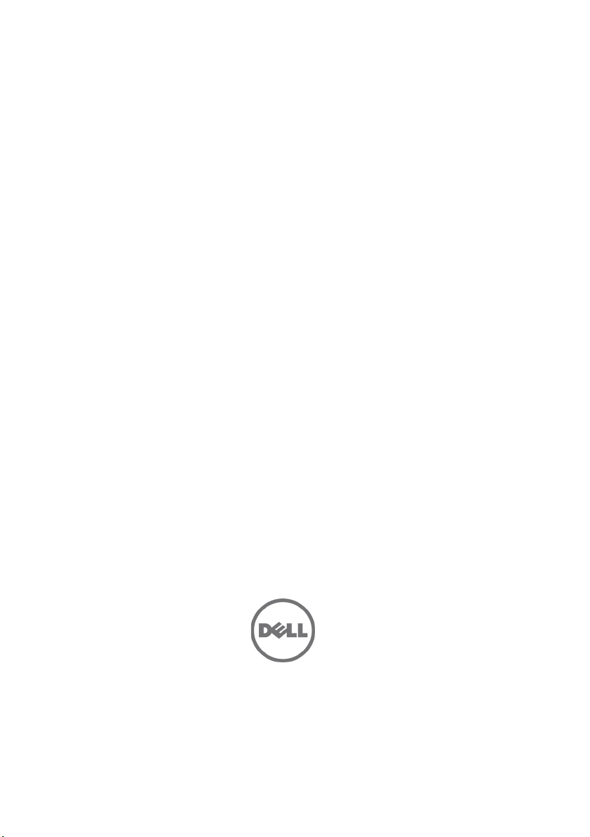
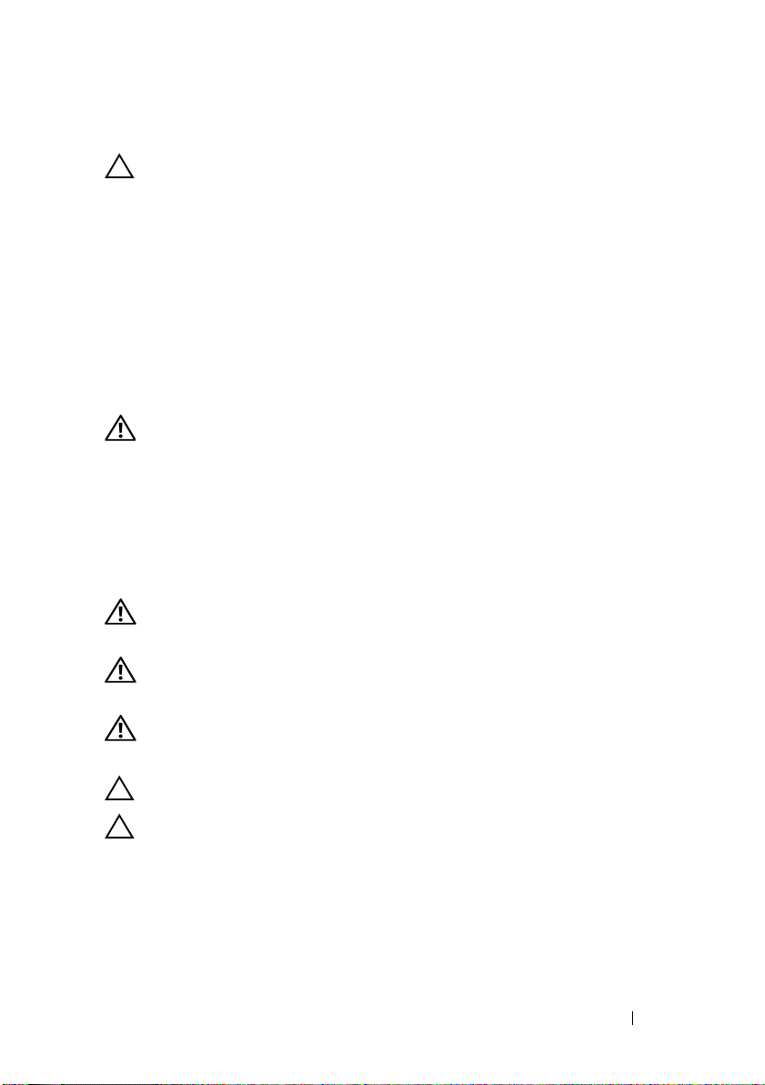
1
Pull on the latch release buttons on the end piece midpoints to open the
rail latches.
2
Align the end pieces of the rails on the vertical rack flanges to seat the pegs
in the bottom hole of the first U and the top hole of the second U. Engage
the back end of the rail until the latch locks in place.
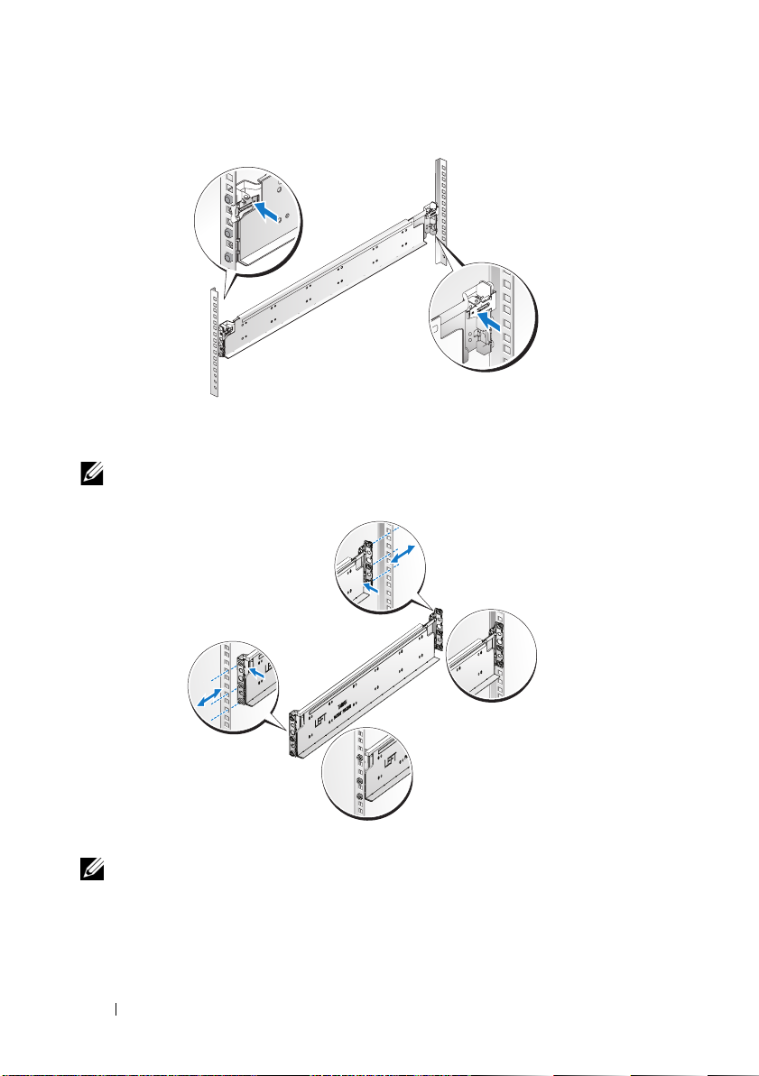
NOTE: The rails can be used in both square-hole and round-hole racks.
Back
Front
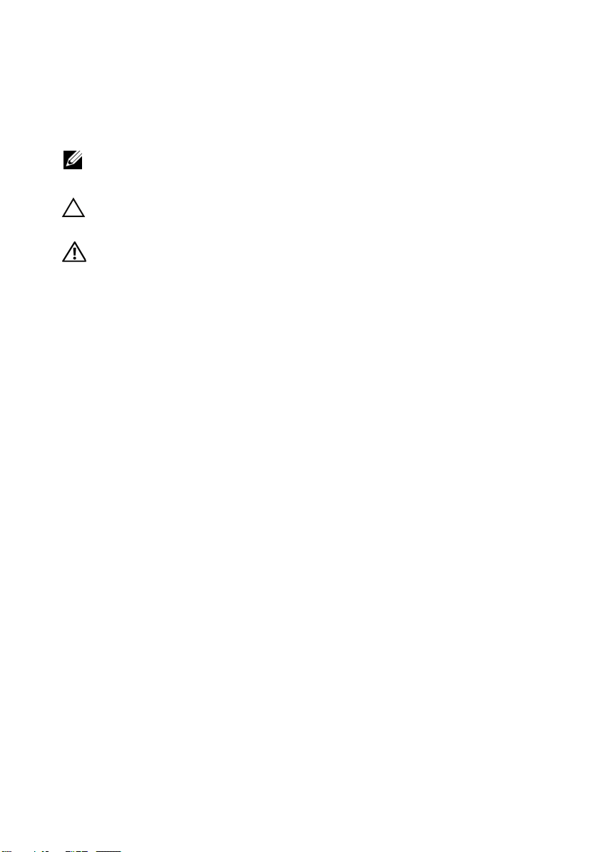
3
Repeat steps 1 to 2 to position and seat the front end piece on the vertical
flange.
NOTE: To remove the rails, pull on the latch release button on the end piece
midpoint and unseat each rail.
4 Installation and Configuration
Page 7
Installing the System
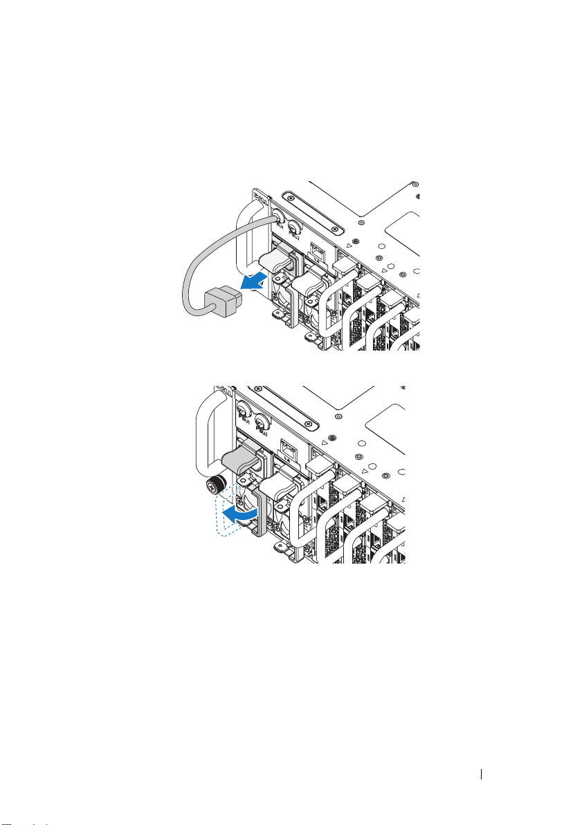
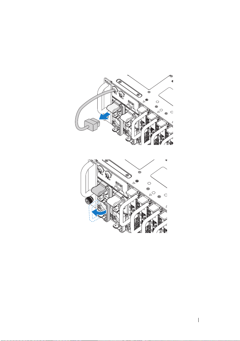
Empty the System Chassis
1
Unplug the power cable from the power supply unit.
.
2
Pull out the power supply unit handle.
Installation and Configuration 5
Page 8

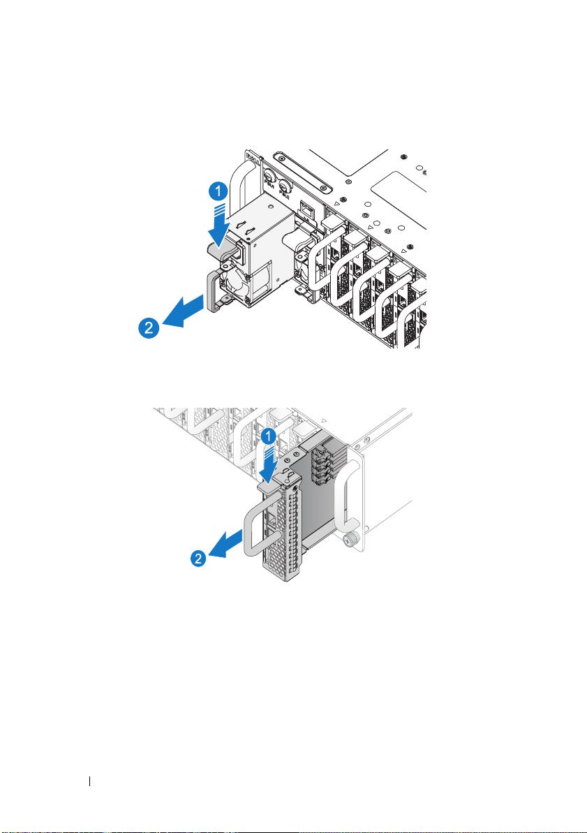
3
Press down on the release latch .
4
Pull the power supply unit out of the system .
5
Press the release latch down .
6
Pull the sled out of the system .
6 Installation and Configuration
Page 9
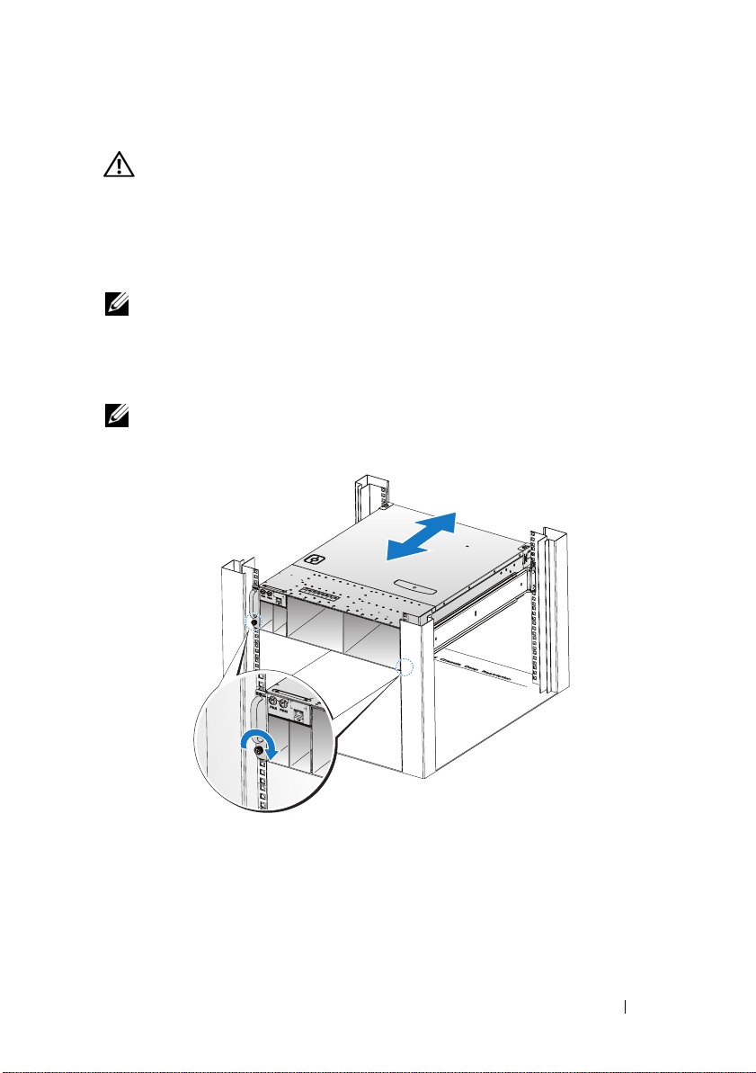
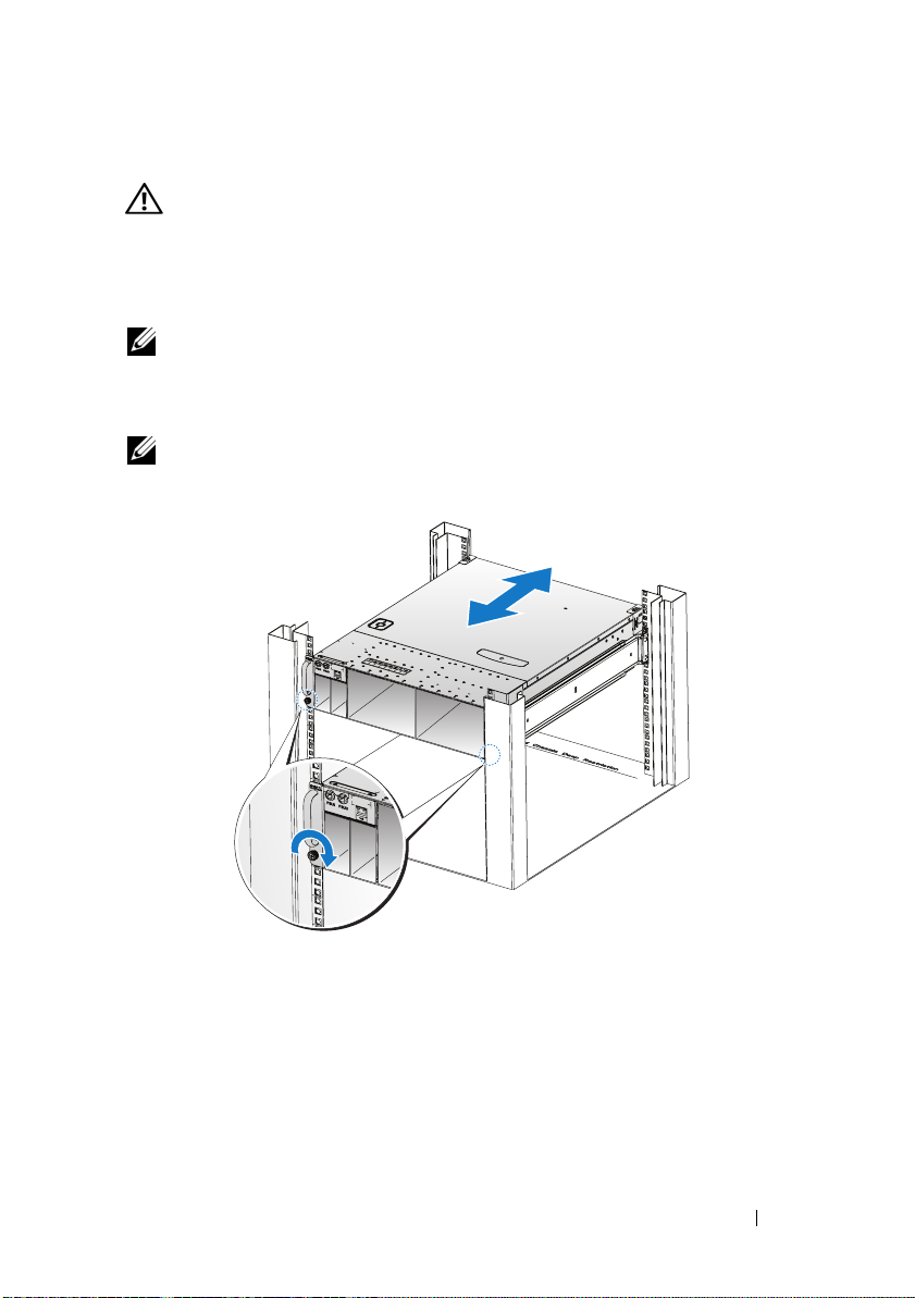
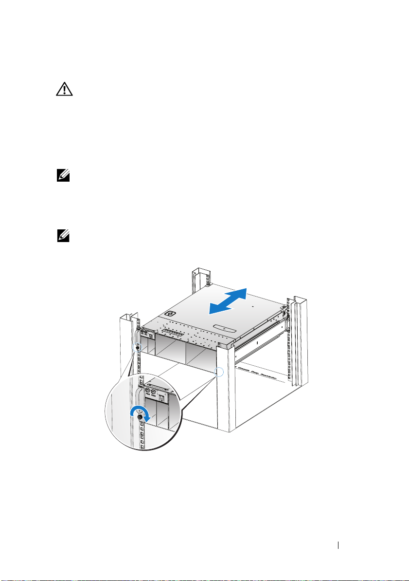
Installing the System Into the Rack
WARNING: Whenever you need to lift the system, get others to assist you. To
avoid injury, do not attempt to lift the system by yourself.
1
Slide the system into the rack.
2
If present, remove the chassis stabilizer shipping bracket (optional) from
the rack.
NOTE: To transport systems already installed in the rack, ensure that the two
chassis stabilizer shipping brackets (optional) are in place.
3
Tighten the captive thumbscrews to secure the ears of the system to the
front of the rack.
NOTE: Make sure the latch release mechanism is engaged correctly.
Installation and Configuration 7
Page 10
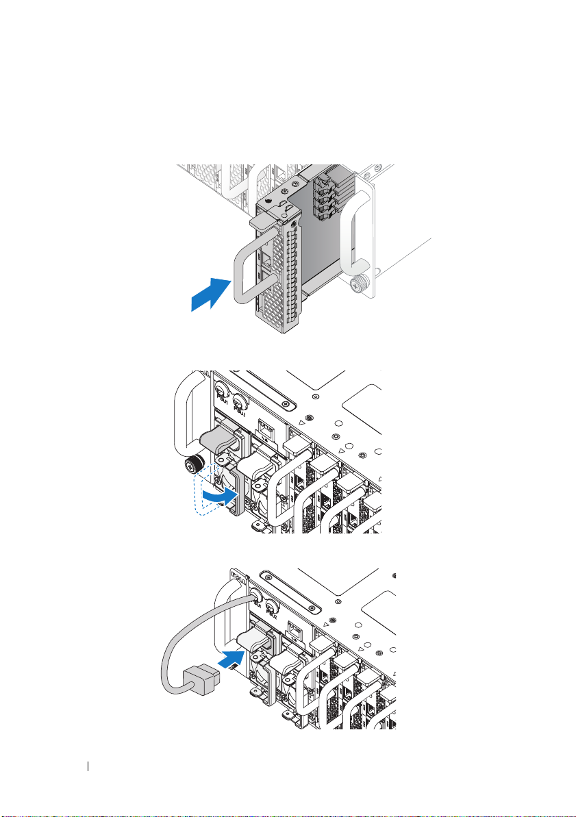
Populate the System
1
Push the power supply unit into the system until flush with the case and
the release latch locks.
2
Close the power supply unit handle.
3
Plug the chassis power cable into the power supply unit.
8 Installation and Configuration
Page 11
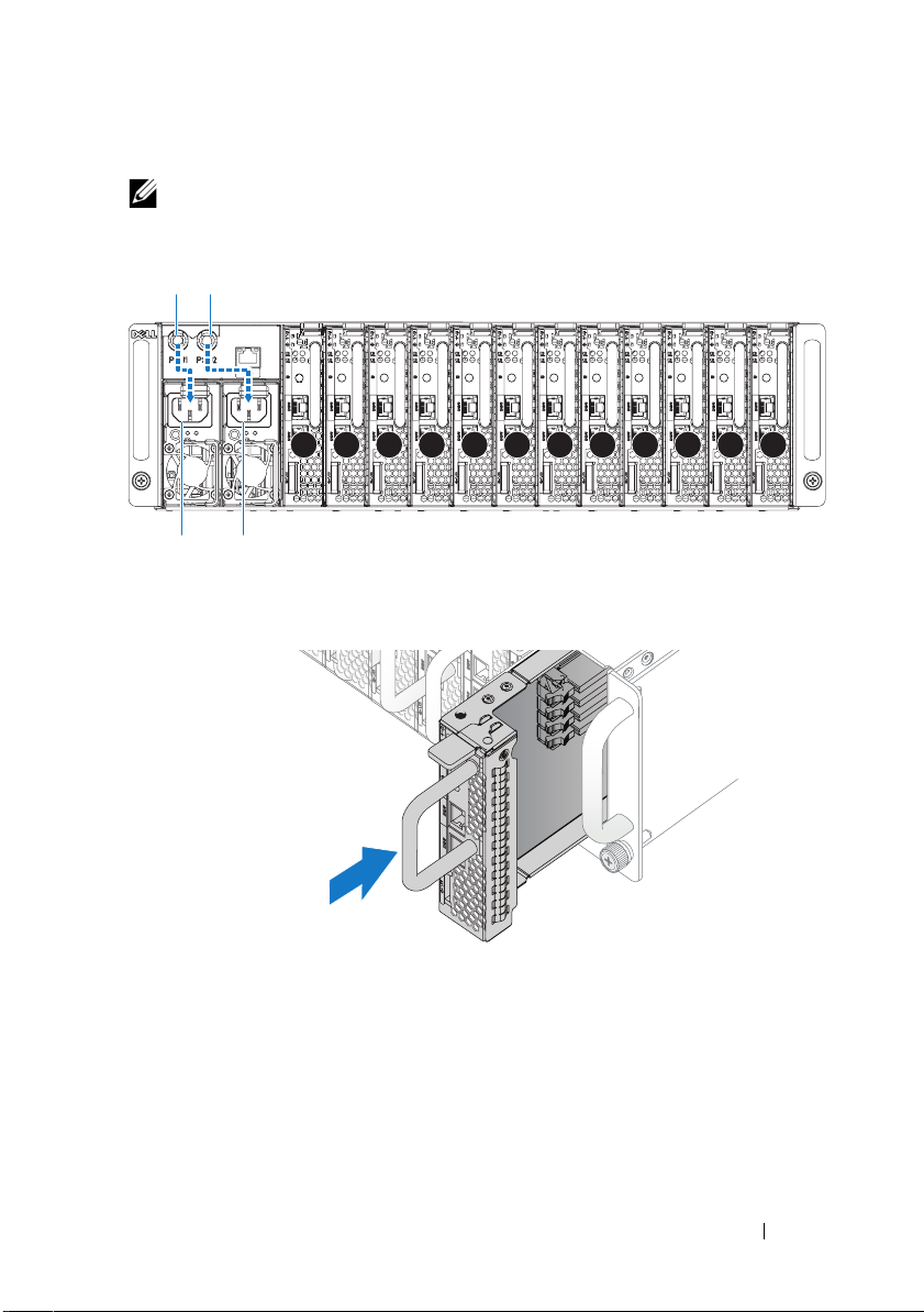
NOTE: The correct configuration of the integral chassis AC power cables to the
PSU sockets is as shown in the following illustration.
PSU1 PSU2
1 2 3 4 5 6 7 8 9 10 11 12
PSU1 PSU2
4
Push the sled into the system until flush with the case and the release latch
locks.
Installation and Configuration 9
Page 12
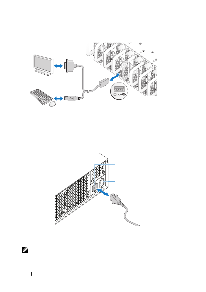
Connecting the Keyboard, Mouse, and Monitor
The connector on the front of your system has an icon indicating which cable
to plug in. Connect a keyboard, mouse, or monitor (optional).
Connecting the Power Cables
1
On the back of the system, connect the mains power cable to the system’s
power socket.
AC Port 2
AC Port 1
2
Plug the other end of the power cables into a grounded electrical outlet or
a separate power source such as an uninterrupted power supply or a power
distribution unit.
NOTE: AC Port 1 provides power to PSU1, AC Port 2 provides power to PSU2. For
more information, see step 3 of Populate the System.
10 Installation and Configuration
Page 13

Turning On the System
When connected to a power source the system automatically powers on. See
Using the Baseboard Management Controller Guide at
support.dell.com/manuals.
Complete the Operating System Setup
To install an operating system for the first time, see the installation and
configuration documentation for your operating system. Be sure the
operating system is installed before installing hardware or software not
purchased with the system.
Supported Operating Systems
• Microsoft Windows Server 2008 R2 Enterprise
• Microsoft HPC Server 2008 R2
• Microsoft Windows Server 2008 R2 Hyper-V
• Red Hat Enterprise Linux 6.0 (64-bit)
• Red Hat Enterprise 5 Update 5 (64-bit)
• SUSE Linux Enterprise Server 11 Service Pack 1 (64-bit)
• VMware ESX 4.1 Update 1
• VMware ESXi 4.1 Update 1 (Embedded option for SDHC)
• Citrix XenServer 5.6 Feature Pack 1
NOTE: For the latest information on supported operating systems, see
support.dell.com.
Installation and Configuration 11
Page 14
Other Information You May Need
WARNING:
system. Warranty information may be included within this document or as
a separate document.
See the Hardware Owner’s Manual at support.dell.com/manuals for
information about system features, troubleshooting, and component
replacement.
See Using the Baseboard Management Controller Guide at
support.dell.com/manuals.
NOTE: Always check for updates on support.dell.com/manuals and read the
updates first because they often supersede information in other documents.
See the safety and regulatory information that shipped with your
Información de la NOM (sólo para México)
La información que se proporciona a continuación aparece en el dispositivo
descrito en este documento, en cumplimiento de los requisitos de la Norma
Oficial Mexicana (NOM):
Importador Dell Inc. de México, S.A. de C.V.
Paseo de la Reforma 2620 – 11° Piso
Col. Lomas Altas
11950 México, D.F.
Número de modelo B04S
Voltaje de alimentación 200-240 V CA
Frecuencia 50/60 Hz
Consumo eléctrico 9 A para cada entrada de alimentación
12 Installation and Configuration
Page 15

Technical Specifications
Processor (Per System Board)
Processor type Intel Xeon Processor E3-1200 product
family
Expansion Bus (Per System Board)
Bus type PCI-E x8 Gen 2
Expansion slots Mezzanine connector
Memory (Per System Board)
Architecture Dual Channel Unbuffered DDR3
1066/1333
Memory module sockets 4
Memory module capacities
Minimum RAM 2 GB
Maximum RAM 32 GB
Drives (Per System Board)
2.5" hard drives SAS 6 Gb (4 channels)
SATA 3 Gb (4 channels)
3.5" hard drives SAS 6 Gb (2 channels)
SATA 3 Gb (2 channels)
Connectors (Per System Board)
Front
NIC 10/100/1G (RJ45)
USB 2.0 (through Y-cable)
Video (DB15) (through Y-cable)
Video
Video type AST2050
Video memory 8 MB DDR2 SDRAM
2
2
1
Technical Specifications 13
Page 16
Power
AC power supply (per power supply)
Wa t ta g e
Vo lt ag e
Heat dissipation
Maximum inrush current
Physical
Height 13 cm (5.1 in)
Width 44.7 cm (17.6 in)
Depth 75 cm (29.5 in)
Weight (loaded: maximum weight) 8-sled configuration:
Weight (empty) 8-sled configuration:
1400 W
200-240 VAC, 50/60 Hz
55.67 BTU/hr max
55 A max
42.4 kg (93.48 lbs.)
12-sled configuration:
48.13 kg (106.11 lbs.)
27.4 kg (60.41 lbs.)
12-sled configuration:
32.02 kg (70.59 lbs.)
Environmental
NOTE: For additional information about environmental measurements for specific
system configurations, see dell.com/environmental_datasheets.
Temperature
Operating
10°C to 35°C (50°F to 95°F) with a
maximum temperature gradation of 10°C
(per hour)
NOTE: For altitudes above 2,950 feet, the
maximum operating temperatures derated
to 1°F/550 ft.
Storage
–40°C to 65°C (-40°F to 149°F) with a
maximum temperature gradation of 20°C
per hour
14 Technical Specifications
Page 17

Environmental (continued)
Relative Humidity
Operating
Storage
Maximum vibration
Operating
Storage
Maximum shock
Operating
Storage
Altitude
Operating
Storage
Airborne Contaminant Level
Class
20% to 80% (noncondensing) with a
maximum humidity gradation of 10% per
hour
5% to 95% (noncondensing)
0.26 Grms at 5–350 Hz
1.87 Grms at 10–500 Hz for 15 minutes
One shock pulse in the positive z axis
(one pulse on each side of the system) of
31 G for 2.6 ms in the operational
orientation
Six consecutively executed shock pulses
in the positive and negative x, y, and z
axes (one pulse on each side of the
system) of 71 G for up to 2 ms.
Six consecutively executed shock pulses
in the positive and negative x, y, and z
axes (one pulse on each side of the
system) of 22 G faired square wave pulse
with velocity change at 200 inches/second
-16 to 3,048 m (-50 to 10,000 ft.)
-16 to 10,600 m (-50 to 35,000 ft.)
G1 as defined by ISA-S71.04-1985
Technical Specifications 15
Page 18

Acoustics
Sound Power (Units: LwAd-UL,bels)
Idle in 23 ± 2°C ambient
SPEC power at 50% in 23 ± 2°C
ambient
<= 7.0
<= 7.2
NOTE: LwAd-UL is the upper limit sound power level (LwAd) calculated by ISO 9296
(1988) and measured in accordance with ISO7779 (1999).
16 Technical Specifications
Page 19

Dell PowerEdge C5220
系统
使用入门
管制型号
B04S
Page 20
注、小心和警告
注:
“注”表示帮助您更好地使用系统的重要信息。
小心:“小心”表示如果不遵循说明,就有可能损坏硬件或导致数据丢失。
警告:
“警告”表示可能会导致财产损失、人身伤害甚至死亡。
____________________
本出版物中的信息如有更改,恕不另行通知。
©
2011 Dell Inc.
未经
Dell Inc.
本文中使用的商标:
®
Intel
Xeon
Windows
®
Red Hat
标。
SUSE™ 是 Novell Inc.
Citrix Systems, Inc.
在美国或其它国家/地区的注册商标或商标。
本出版物中述及的其它商标和商品名称是指拥有相应商标和商品名称的公司或其产品。
Dell Inc.
版权所有,翻印必究。
书面许可,严禁以任何形式复制这些材料。
®
®
是 Microsoft Corporation
和 Red Hat Enterprise Linux® 是 Red Hat, Inc.
对不属于自己的商标和商品名称不拥有任何专有权。
Dell™、DELL
是
Intel Corporation
在美国和其它国家/地区的商标。
在美国和/或其它国家/地区的注册商标或商标。
徽标和
在美国和其它国家/地区的注册商标。
PowerEdge™ 是 Dell Inc.
在美国和/或其它国家/地区的商标或注册商标。
在美国和/或其它国家/地区的注册商
Citrix
的商标。
®
、
Xen
VMware
®
Intel
Microsoft
®
和
®
、
XenServer
®
是 VMWare, Inc.
和
®
是
管制型号
2011 年 4 月 P/N MP9TK Rev. A00
B04S
Page 21
小心:受限访问位置
此服务器仅用于安装在由
个条件的受限访问位置中:
•
仅维修人员或对该位置施加限制的理由以及应当采取的防备措施已完
全领会的用户,可对此服务器进行访问。
•
通过同时使用工具或锁和钥匙,或其它安全手段来访问,并且是由位
置的可靠授权来控制的。
IEC 60950-1: 2001 的 Cl. 1.2.7.3
定义的满足下列两
安装和配置
警告:
打开系统包装
打开系统包装并检查各个组件。
安装免工具拆装导轨解决方案
警告:
系统。
警告:
坏,在安装和拆卸时,必须给系统提供足够的支撑。
警告:
机架设备必须对系统提供足够的通风以维持适当冷却。
执行下列步骤之前,请阅读并遵循系统随附的安全说明。
如需抬高系统时,请让别人帮您。为避免受伤,请勿尝试独自提起
系统未固定到机架上或未安装在导轨上。为避免人身伤害或系统损
为避免可能的电击伤害,机架安装需要第三根导线安全接地连接器。
小心:在方孔机架中安装导轨时,务必确保方形插销穿过方孔。
小心:方形螺栓必须与机架柱对齐以正确安装。
安装和配置 19
Page 22
1
拔起尾段正中央的闩锁释放按钮以打开导轨闩锁。
2
在机架垂直凸缘上对齐导轨的尾段,将插销放在第一个
第二个
注:
的顶孔中。使导轨后端咬合,直到闩锁锁定到位。
U
导轨可以在方孔和圆孔机架中使用。
Back
Front
的底孔中和
U
3
重复步骤
注:
1 至 2
要卸下导轨,请拔起尾段正中央的闩锁释放按钮并取出每个导轨。
20 安装和配置
,在垂直凸缘上放置和固定前端部分。
Page 23
安装系统
清空系统机箱
1
拔下电源设备的电源电缆。
.
2
拉出电源设备手柄。
安装和配置 21
Page 24
3
按下释放闩锁
4
拉出系统中的电源设备
5
按下释放闩锁
6
拉出系统中的底座
。
。
。
。
22 安装和配置
Page 25
将系统安装到机架中
警告:
系统。
1
将系统滑入到机架中。
2
如果存在运输时稳固机箱的支架 (可选),请将其从机架上卸下。
注:
位(可选)。
3
拧紧系留指旋螺钉,将系统吊耳固定到机架正面。
注:
如需抬高系统时,请让别人帮您。为避免受伤,请勿尝试独自提起
要运输已经安装在机架上的系统,请确保两个运输时稳固机箱的支架到
确保闩锁释放装置正确啮合。
安装和配置 23
Page 26

安装系统
1
将电源设备推入系统,直到与框架对齐并且释放闩锁锁定。
2
关闭电源设备手柄。
3
将机箱电源电缆插入电源设备。
24 安装和配置
Page 27

注:
与 PSU 插槽连接的集成机箱交流电源电缆的正确配置如下图所示。
PSU1 PSU2
1 2 3 4 5 6 7 8 9 10 11 12
PSU1 PSU2
4
将底座推入系统,直到与框架对齐并且释放闩锁锁定。
安装和配置 25
Page 28

连接键盘、鼠标和显示器
系统正面的连接器上有一个图标,指示要插入的电缆。连接键盘、鼠标或显
示器(可选)。
连接电源电缆
1
在系统背面,将主电源电缆连接到系统的电源插槽。
AC Port 2
AC Port 1
2
将电源电缆的另一端插入接地的电源插座或单独的电源,如不间断电
源设备
(UPS)
注:
AC 端口 1 为 PSU1 供电, AC 端口 2 为 PSU2 供电。有关详情,请参阅步
骤 3:“安装系统”。
26 安装和配置
或配电装置。
Page 29

开启系统
连接到电源时,系统自动开机。请参阅
用底板管理控制器指南》。
support.dell.com/manuals
上的《使
完成操作系统安装
第一次安装操作系统时,请参阅操作系统的安装和配置说明文件。请确保先
安装操作系统,然后再安装未随系统一起购买的硬件或软件。
支持的操作系统
•
Microsoft Windows Server 2008 R2 Enterprise
•
Microsoft HPC Server 2008 R2
•
Microsoft Windows Server 2008 R2 Hyper-V
•
Red Hat Enterprise Linux 6.0
•
Red Hat Enterprise 5 Update 5
•
SUSE Linux Enterprise Server 11 Service Pack 1
•
VMware ESX 4.1 Update 1
•
VMware ESXi 4.1 Update 1
•
Citrix XenServer 5.6 Feature Pack 1
注:
有关支持的操作系统的最新信息,请访问 support.dell.com。
(
(
SDHC
位)
64
(
位)
64
的嵌入式选项)
(
64
位)
安装和配置 27
Page 30

可能需要的其它信息
警告:
件中,也可能作为单独的说明文件提供。
请参阅系统随附的安全与管制信息。保修信息可能包括在该说明文
有关系统功能、故障排除和组件更换的信息,请参阅
support.dell.com/manuals
请参阅
support.dell.com/manuals
注:
请经常访问 support.dell.com/manuals 以获得更新,并首先阅读这些更
新,因为这些更新通常会取代其他说明文件中的信息。
上的《硬件用户手册》。
上的《使用底板管理控制器指南》。
28 安装和配置
Page 31

技术规格
处理器(每个系统板)
处理器类型
扩展总线(每个系统板)
总线类型
扩充槽 夹层卡连接器
内存(每个系统板)
体系结构 双通道非缓冲
内存模块插槽
内存模块容量
最小
RAM
最大
RAM
驱动器(每个系统板)
英寸硬盘驱动器
2.5
英寸硬盘驱动器
3.5
连接器(每个系统板)
正面
NIC 10/100/1G (RJ45)
USB 2.0
视频
视频
视频类型
视频内存
(通过
(DB15)
形电源线)
Y
(通过
形电源线)
Y
Intel Xeon
PCI-E x8 Gen 2
4
2 GB
32 GB
SAS 6 Gb(4
SATA 3 Gb(4
SAS 6 Gb(2
SATA 3 Gb(2
2
2
1
AST2050
8 MB DDR2 SDRAM
处理器
E3-1200
DDR3 1066/1333
个通道)
个通道)
个通道)
个通道)
产品系列
技术规格 29
Page 32

电源
交流电源设备(每个电源设备)
功率
电压
散热
最大涌入电流
物理规格
高度
宽度
厚度
重量(已加载:最大重量)
重量(空置)
环境参数
1400 W
200-240 VAC,50/60 Hz
最大为
55.67 BTU/
最大为
55 A
厘米(
13
厘米(
44.7
厘米(
75
底座配置:
8
42.4
底座配置:
12
48.13
底座配置:
8
27.4
底座配置:
12
32.02
英寸)
5.1
17.6
29.5
千克(
千克(
千克(
千克(
英寸)
注:有关特定系统配置的环境测量值的其它信息,请参阅
dell.com/environmental_datasheets。
温度
运行时
10°C 至 35
度变化梯度为每小时
°C(50°F 至
注:海拔高度在 900 米以上时,每升高
300 米,最高操作温度降低 1°C。
存储时
-40°C 到 65
最大温度变化梯度为每小时
°C(
小时
英寸)
磅)
93.48
磅)
106.11
磅)
60.41
磅)
70.59
°F),最大温
95
°C
10
-40°F 到 149
°F),
°C
20
30 技术规格
Page 33

环境参数 (续)
相对湿度
运行时
存储时
最大振动
运行时
存储时
最大撞击
运行时
存储时
海拔高度
运行时
存储时
气载污染物级别
级别
20% 至 80%
为每小时
5% 至 95%
5 - 350 Hz 时为 0.26 Grms
在
10 - 500 Hz、1.87 Grms
分钟
15
在操作方向上,z 轴正方向可承受一个
31 G
脉冲),可持续
x、y 和 z
71 G
脉冲),最长可持续
x、y 和 z
22 G
面承受一个脉冲),速度变化为
寸/秒
-16 至 3,048 米(-50 至 10,000
-16 至 10,600 米(-50 至 35,000
(依据
G1
准)
(非冷凝),最大湿度变化
10%
(非冷凝)
时,可持续
的撞击脉冲(系统每一面承受一个
毫秒
2.6
轴正负方向上可承受连续六个
的撞击脉冲(系统每一面承受一个
毫秒。
2
轴正负方向上可承受连续六个
正弦波脉冲的撞击脉冲(系统每一
200
英尺)
英尺)
ISA-S71.04-1985
定义的标
英
技术规格 31
Page 34

声音
声功率(单位:
23 ± 2°C
23 ± 2°C
时
环境温度下闲置时
环境温度下电源规格为
LwAd-UL
,贝尔)
50%
<= 7.0
<= 7.2
注:LwAd-UL 是由 ISO 9296 (1988) 计算出并根据 ISO7779 (1999) 测量的上限声功率
级 (LwAd)。
32 技术规格
Page 35

Model Sesuai Regulasi B04S
Dell PowerEdge C5220
Mengaktifkan
Sistem Anda
Page 36

Catatan, Perhatian, dan Peringatan
CATATAN: CATATAN menunjukkan informasi penting yang membantu Anda
mengoptimalkan penggunaan sistem Anda.
PERHATIAN: PERHATIAN menunjukkan kerusakan potensial pada perangkat
keras atau kehilangan data jika Anda tidak mengikuti instruksi yang diberikan.
PERINGATAN: PERINGATAN menunjukkan kemungkinan kerusakan pada harta
benda, cedera diri, atau kematian.
____________________
Informasi dalam publikasi ini dapat berubah tanpa pemberitahuan.
© 2011 Dell Inc. Hak Cipta Dilindungi Undang-undang.
Dilarang keras memperbanyak materi ini dengan cara apa pun tanpa izin tertulis dari Dell Inc.
Merek-merek dagang yang digunakan di dalam teks ini: Dell™, logo DELL, dan PowerEdge™ adalah
merek-merek dagang dari Dell Inc. Intel
Corporation di A.S. dan negara lain. Microsoft
dagang terdaftar dari Microsoft Corporation di Amerika Serikat dan/atau negara lain. Red Hat
Red Hat Enterprise Linux
dan/atau negara-negara lain. SUSE™ adalah merek dagang dari Novell, Inc. di Amerika Seriat dan
negara-negara lainnya. Citrix
dagang dari Citrix Systems, Inc. di Amerika Serikat dan/atau negara-negara lainnya. VMware
merek dagang terdaftar dari VMware, Inc. di Amerika Serikat dan/atau negara-negara lainnya.
Merek dagang dan nama dagang lain mungkin digunakan dalam dokumen ini untuk merujuk ke pihak
lain yang memiliki hak kekayaan intelektual atas merek dan nama atau produk mereka. Dell Inc.
menyangkal kepentingan kepemilikan apa pun atas merek dagang dan nama dagang selain miliknya
sendiri.
®
adalah merek dagang terdaftar dari Red Hat, Inc. di Amerika Serikat
®
®
dan Intel® Xeon® adalah merek dagang terdaftar dari Intel
®
dan Windows® merupakan merek dagang atau merek
, Xen®, and XenServer® adalah merek dagang terdaftar atau merek
®
®
adalah
dan
Model Sesuai Regulasi B04S
2011-04 No. Komp. MP9TK Rev. A00
Page 37

PERHATIAN: Lokasi Akses Terbatas
Server ini dimaksudkan untuk instalasi di lokasi-lokasi akses terbatas saja
sebagaimana didefinisikan di dalam Cl.1.2.7.3 dari IEC 60950-1: 2001 di
mana kedua syarat berikut ini berlaku:
• Akses hanya dapat diperoleh oleh petugas servis atau pengguna yang telah
diberitahu mengenai alasan-alasan pembatasan yang diterapkan pada
lokasi tersebut dan tentang tindakan pencegahan yang harus dilakukan.
• Akses dilakukan melalui penggunaan alat atau kunci dan anak kunci, atau
sarana pengaman lainnya, dan dikontrol oleh pihak berwenang yang
bertanggung jawab atas lokasi tersebut.
Instalasi dan Konfigurasi
PERINGATAN: Sebelum melakukan prosedur berikut ini, bacalah dan ikuti
petunjuk keselamatan yang diberikan bersama sistem.
Membuka Kemasan Sistem
Buka kemasan sistem Anda dan kenali setiap komponen.
Memasang Tool-Less Rail Solution
PERINGATAN: Bilamana Anda ingin mengangkat sistem, mintalah orang lain
untuk membantu Anda. Untuk mencegah cedera, jangan mencoba mengangkat
sistem sendirian.
PERINGATAN: Sistem belum ditempatkan pada rak atau dipasang pada rel. Untuk
menghindari cedera pada orang atau kerusakan pada sistem, Anda harus
menopang sistem secara memadai selama pemasangan atau pembongkaran.
PERINGATAN: Untuk menghindari bahaya sengatan listrik, diperlukan konduktor
pembumian untuk pemasangan rak. Peralatan rak harus memberikan aliran udara
yang memadai ke sistem untuk mempertahankan pendinginan yang memadai.
PERHATIAN: Sewaktu memasang rel di dalam rak lubang persegi, penting untuk
memastikan bahwa pasak persegi bergeser melalui lubang persegi.
PERHATIAN: Stud-stud persegi harus rata dengan tiang-tiang rak agar dapat
dipasang sebagaimana mestinya.
Instalasi dan Konfigurasi 35
Page 38

1
Tarik tombol-tombol pelepas pengunci yang ada di tengah bagian ujung
untuk membuka pengunci-pengunci rel.
2
Sejajarkan bagian-bagian ujung dari rel pada flensa rak vertikal untuk
mendudukkan pasak-pasak pada lubang bawah U pertama dan pada
lubang atas U kedua. Sambungkan ujung belakang rel-rel sampai pengunci
mengunci pada tempatnya.
CATATAN: Rel-rel dapat digunakan baik pada rak lubang persegi maupun pada rak
lubang bulat.
Back
Front
3
Ulangi langkah 1 sampai 2 untuk memposisikan dan mendudukkan bagian
ujung depan pada flensa vertikal.
CATATAN: Untuk melepaskan rel-rel, tarik tombol pelepas pengunci yang ada di
tengah bagian ujung dan lepaskan setiap rel dari dudukannya.
36 Instalasi dan Konfigurasi
Page 39

Memasang Sistem
Kosongkan Casis Sistem
1
Lepaskan kabel daya dari unit pencatu daya.
.
2
Tarik keluar tangkai unti pencatu daya.
Instalasi dan Konfigurasi 37
Page 40

3
Tekan pada pengunci pelepas (release latch) .
4
Tarik unit pencatu daya ke luar sistem .
5
Tekan pengunci pelepas (release latch) .
6
Tarik sled keluar sistem .
38 Instalasi dan Konfigurasi
Page 41
Memasang sistem pada rak.
PERINGATAN: Bilamana Anda ingin mengangkat sistem, mintalah orang lain
untuk membantu Anda. Untuk mencegah cedera, jangan mencoba mengangkat
sistem sendirian.
1
Geser sistem ke dalam rak.
2
Kalau ada, lepaskan braket pengiriman penstabil casis (chassis stabilizer
shipping bracket) (opsional) dari rak.
CATATA N: Untuk mengirimkan sistem yang sudah terpasang pada rak, pastikan
bahwa kedua braket pengiriman penstabil casis (opsional) telah terpasang.
3
Kencangkan captive thumbscrew (sekrup yang bisa diputar dengan jari)
untuk mengunci kuping-kuping sistem ke bagian depan flensa rak.
CATATA N: Pastikan mekanisme pelepas pengunci dioperasikan dengan benar.
Instalasi dan Konfigurasi 39
Page 42

Populasikan Sistem
1
Dorong unit pencatu daya ke dalam sistem sampai rata dengan kas (case)
dan lepaskan penguncinya.
2
Tutup tangkai unit pencatu daya.
3
Pasang kabel daya casis pada unti pencatu daya.
40 Instalasi dan Konfigurasi
Page 43

CATATA N: Konfigurasi yang benar dari kabel daya AC casis integral ke soket unit
pencatu daya (PSU) diperlihatkan dalam ilustrasi berikut ini.
PSU1 PSU2
1 2 3 4 5 6 7 8 9 10 11 12
PSU1 PSU2
4
Dorong unit pencatu daya ke dalam sistem sampai rata dengan kas (case)
dan lepaskan penguncinya.
Instalasi dan Konfigurasi 41
Page 44

Menghubungkan Keyboard, Mouse, dan Monitor
Konektor pada bagian depan sistem Anda memiliki ikon yang menunjukkan
kabel mana yang harus dipasang. Hubungkan keyboard, mouse, dan monitor
(opsional).
Menghubungkan Kabel Daya
1
Pada bagian belakang sistem, hubungkan kabel daya ke soket daya sistem.
AC Port 2
AC Port 1
2
Tancapkan ujung kabel daya yang lain ke stopkontak listrik yang
ditanahkan atau sumber daya terpisah seperti catu daya tak terputus atau
unit distribusi daya.
CATATAN: AC Port 1 memberikan daya ke PSU1, AC Port 2 memberikan daya ke
PSU2. Untuk informasi lebih lanjut, lihat langkah 3 tentang Mengisi Sistem.
42 Instalasi dan Konfigurasi
Page 45

Menyalakan Sistem
Ketika terhubung ke sumber tenaga listrik, sistem akan hidup secara otomatis.
Lihat Panduan Penggunaan Baseboard Management Controller di
support.dell.com/manuals.
Menyelesaikan Pengaturan Sistem Operasi
Untuk menginstal sistem operasi untuk pertama kalinya, lihat dokumentasi
instalasi dan konfigurasi untuk sistem operasi Anda. Pastikan bahwa sistem
operasi telah terinstal sebelum Anda menginstal perangkat keras atau
perangkat lunak yang tidak dibeli bersama sistem.
Sistem Operasi Yang Didukung
• Microsoft Windows Server 2008 R2 Enterprise
• Microsoft HPC Server 2008 R2
• Microsoft Windows Server 2008 R2 Hyper-V
• Red Hat Enterprise Linux 6.0 (64-bit)
• Red Hat Enterprise 5 Update 5 (64-bit)
• SUSE Linux Enterprise Server 11 Service Pack 1 (64-bit)
• VMware ESX 4.1 Update 1
• VMware ESXi 4.1 Update 1 (Embedded option for SDHC)
• Citrix XenServer 5.6 Feature Pack 1
CATATA N: Untuk informasi terbaru mengenai sistem pengoperasian yang
didukung, kunjungi support.dell.com.
Instalasi dan Konfigurasi 43
Page 46

Informasi Lain yang Mungkin Anda Perlukan
PERINGATAN:
dengan sistem Anda. Informasi garansi mungkin disertakan dalam dokumen ini
atau sebagai dokumen yang terpisah.
Lihat Buku Panduan Pemilik Perangkat Keras (Hardware Owner’s Manual)
di support.dell.com/manuals untuk mendapatkan informasi mengenai
fitur-fitur sistem, cara mengatasi masalah, dan penggantian komponen.
Lihat Panduan Penggunaan Baseboard Management Controller di
support.dell.com/manuals.
CATATAN: Selalu periksa update di situs support.dell.com/manuals dan baca
update terlebih dahulu karena biasanya update tersebut menggantikan informasi
dalam dokumen.
Lihat informasi keselamatan dan peraturan yang disertakan
44 Instalasi dan Konfigurasi
Page 47

Spesifikasi Teknis
Prosesor (Per Papan Sistem)
Tipe prosesor Keluarga produk Intel Xeon Processor
E3-1200
Bus Expansi (Per Papan Sistem)
Tipe bus PCI-E x8 Gen 2
Slot ekspansi Mezzanine connector
Memori (Per Papan Sistem)
Arsitektur Dual Channel Unbuffered DDR3
1066/1333
Soket modul memori 4
Kapasitas modul memori
RAM minimum 2 GB
RAM maksimum 32 GB
Drive (Per Papan Sistem)
2.5" hard drives SAS 6 Gb (4 channels)
SATA 3 Gb (4 channels)
3.5" hard drives SAS 6 Gb (2 channels)
SATA 3 Gb (2 channels)
Konektor (Per Papan Sistem)
Depan
NIC 10/100/1G (RJ45)
USB 2.0 (melalui kabel Y)
Video (DB15) (melalui kabel Y)
Video
Tipe video AST2050
Memori video 8 MB DDR2 SDRAM
2
2
1
Spesifikasi Teknis 45
Page 48

Daya
Catu daya AC (per catu daya)
Wat t Da ya
Te ga n ga n
Pelepasan panas
Lonjakan arus maksimum
Fisik
Tinggi 13 cm (5,1 in)
Lebar 44,7 cm (17,6 in)
Panjang 75 cm (29,5 in)
Bobot (bermuatan: bobot maksimum) konfigurasi 8 sled:
Berat (kosong) konfigurasi 8 sled:
1400 W
200-240 VAC, 50/60 Hz
Maks 55,67 BTU/jam
maks. 55 A
42,4 kg (93,48 pon)
konfigurasi 12 sled:
48,13 kg (106,11 pon)
27.4 kg (60.41 lbs.)
konfigurasi 12 sled:
32,02 kg (70,59 pon)
Lingkungan
CATATAN: Untuk informasi tambahan mengenai pengukuran lingkungan untuk
konfigurasi sistem spesifik, lihat dell.com/environmental_datasheets.
Suhu
Pengoperasian
10° hingga 35°C (50°F hingga 95°F)
dengan gradasi suhu maksimum 10°C
(per jam)
CATATAN: Untuk ketinggian di atas
2.950 kaki, suhu kerja maksimum
diturunkan sebesar 1°F/550 kaki.
Penyimpanan
–40° hingga 65°C (–40° hingga 149°F)
dengan gradasi suhu maksimum 20°C
per jam
46 Spesifikasi Teknis
Page 49

Lingkungan (Bersambung)
Kelembapan Relatif
Pengoperasian
Penyimpanan
Getaran maksimum
Pengoperasian
Penyimpanan
Guncangan maksimum
Pengoperasian
Penyimpanan
Ketinggian
Pengoperasian
Penyimpanan
Tingkat Pencemaran Udara
Kelas
20% sampai 80% (tanpa pengondensasian)
dengan gradasi kelembapan maksimum
sebesar 10% per jam
5% hingga 95% (nonkondensasi)
0,26 Grms pada 5–350 Hz
1,87 Grms pada frekuensi 10–500 Hz
selama 15 menit
Satu pulsa guncangan pada sumbu
z positif (satu pulsa pada setiap sisi sistem)
sebesar 31 G selama 2,6 mdet di dalam
orientasi operasional
Enam pulsa guncangan berturut-turut
pada sumbu x, y, dan z positif dan negatif
(satu pulsa pada setiap sisi sistem) sebesar
71 G untuk hingga 2 mdet.
Enam pulsa guncangan berturut-turut
pada sumbu x, y, dan z positif dan negatif
(satu pulsa pada setiap sisi sistem) sebesar
22 G pulsa gelombang persegi biasa
dengan perubahan kecepatan sebesar
200 inci/detik
–16 sampai 3.048 m (–50 sampai
10.000 kaki)
–16 sampai 10.600 m (–50 sampai
35.000 kaki)
G1 sebagaimana didefinisikan oleh
ISA-S71.04-1985
Spesifikasi Teknis 47
Page 50

Akustik
Daya Suara (Unit: LwAd-UL,bels)
Idle pada suhu lingkungan 23 ± 2°C
daya SPEC sebesar 50% pada suhu
lingkungan 23 ± 2
°
C
<= 7,0
<= 7,2
CATATAN: LwAd-UL adalah batas atas tingkat daya suara (LwAd) yang dihitung oleh
ISO 9296 (1988) dan diukur sesuai dengan ISO7779 (1999).
48 Spesifikasi Teknis
Page 51

認可モデル B04S
Dell PowerEdge C5220
はじめに
Page 52

メモ、注意、警告
メモ: コンピュータを使いやすくするための重要な情報を説明しています。
注意: 手順に従わないと、ハードウェアの損傷やデータの損失につながる
可能性があることを示しています。
警告: 物的損害、けが、または死亡の原因となる可能性があることを示
しています。
____________________
本書の内容は予告なく変更されることがあります。
© 2011 すべての著作権は Dell Inc. にあります。
Dell Inc. の書面による許可のない複製は、いかなる形態においても厳重に禁じられてい
ます。
本書に使用されている商標:Dell™、DELL ロゴ、および PowerEdge™ は Dell Inc. の商標
です。Intel
登録商標です。Microsoft
Microsoft Corporation の商標または登録商標です。Red Hat
Linux
米国およびその他の国における Novell, Inc. の商標です。Citrix
XenServer
商標です。VMware
標です。
商標または製品の権利を主張する事業体を表すためにその他の商標および社名が使用され
ていることがあります。それらの商標や会社名は、一切 Dell Inc. に帰属するものではあり
ません。
®
および Intel® Xeon®は米国およびその他の国における Intel Corporation の
®
は米国および / またはその他の国における Red Hat, Inc. の登録商標です。SUSE™ は
®
は米国および / またはその他の国における Citrix Systems, Inc. の登録商標または
®
および Windows®は米国および / またはその他の国における
®
は米国またはその他の国における VMware, Inc. の登録商標または商
®
および Red Hat Enterprise
®
、Xen®および
認可モデル B04S
2011 年 4 月 P/N MP9TK Rev. A00
Page 53

注意: 立入制限区域
このサーバーは、
制限区域にのみ設置してください。設置については、次の両方の条件が適
用されます。
•
立ち入りは、その区域に制限が適用されている理由と取るべき安全
措置について指導を受けているサービススタッフまたはユーザーに
のみ許可されます。
•
立ち入りは、ツールもしくは錠と鍵、またはその他のセキュリティ
手段を使用して行い、区域を管轄する機関によって制御されます。
IEC 60950-1: 2001 の Cl.1.2.7.3
に定義されている立入
取り付けと設定
警告: 次の手順を実行する前に、システムに付属しているマニュアルの
「安全にお使いいただくために」をお読みください。
システムの開梱
システムを箱から取り出し、同梱品がすべて揃っていることを確認します。
ツールレスレールソリューションの取り付け
警告: システムを持ち上げる必要がある場合は、必ずだれかの手を借り
てください。けがを防ぐため、決してシステムを一人で持ち上げようとし
ないでください。
警告: システムはラックに固定されておらず、レールに取り付けられて
もいません。人身傷害やシステムの損傷を避けるため、取り付けと取り外
しの際にはシステムを十分に支えてください。
警告: 感電の危険を避けるため、ラックの取り付けには第 3 種安全用接地
線が必要です。適切な通気による冷却効果を維持するために、ラック装置
からシステムに十分な空気の流れが必要です。
注意: レールを角型穴のラックに取り付ける際には、角型のペグを角型の
穴に確実に挿入することが重要です。
注意: 角スタッドを正しく取り付けるには、ラックの柱と完全に揃ってい
る必要があります。
取り付けと設定 51
Page 54

1
レールラッチを開くには、エンドピースの中央にあるラッチリリー
スボタンを引きます。
2
レールのエンドピースを垂直ラックフランジに合わせ、ペグを
U
目の
の最下部の穴と
2
番目の
U
の最上部の穴に入れます。ラッチ
が所定の位置にロックされるまで、レールの後端をはめ込みます。
メモ: レールは角型穴と丸型穴の両方のラックに使用できます。
Back
1
番
Front
3
手順
1 ~ 2
を繰り返して、前面のエンドピースを垂直フランジに取
り付けます。
メモ: レールを取り外すには、エンドピースの中央にあるラッチリリース
ボタンを引いて各レールを外します。
52 取り付けと設定
Page 55

システムの取り付け
電源ユニットとスレッドの取り外し
1
電源ユニットから電源ケーブルを外します。
2
電源ユニットのハンドルを引き出します。
取り付けと設定 53
Page 56

3
リリースラッチを押し下げます。
電源ユニットをシステムから引き出します。
4
リリースラッチを押し下げます。
5
スレッドをシステムから引き出します。
6
54 取り付けと設定
Page 57

ラックへのシステムの取り付け
警告: システムを持ち上げる必要がある場合は、必ずだれかの手を借り
てください。けがを防ぐため、決してシステムを一人で持ち上げようとし
ないでください。
1
システムをラックに挿入します。
2
オプションのシャーシスタビライザのシッピングブラケットが取り
付けられている場合は、ラックから取り外します。
メモ: ラックに取り付け済みのシステムを移動する場合は、2 つのシャー
シスタビライザシッピングブラケット(オプション)が取り付けられてい
ることを確認してください。
3
拘束蝶ネジを締めて、システムの両側をラックの前面に固定します。
メモ: ラッチリリース機構が正しく固定されていることを確認してくだ
さい。
取り付けと設定 55
Page 58

電源ユニットとスレッドの取り付け
1
電源ユニットをシステムに挿入します。ケースと同一面になり、リ
リースラッチがロックするまで押し込んでください。
2
電源ユニットのハンドルを閉じます。
3
シャーシの電源ケーブルを電源ユニットに接続します。
56 取り付けと設定
Page 59

メモ: シャーシのインテグラル AC 電源ケーブルを PSU ソケットに接続し
た正しい構成は下図のとおりです。
PSU1 PSU2
1 2 3 4 5 6 7 8 9 10 11 12
PSU1 PSU2
4
スレッドをシステムに挿入します。ケースと同一面になり、リリー
スラッチがロックするまで押し込んでください。
取り付けと設定 57
Page 60

キーボード、マウス、モニターの接続
システム前面のコネクタには、どのケーブルを接続するかを示すアイコン
があります。キーボード、マウス、またはモニター(オプション)を接続
します。
電源ケーブルの接続
1
システムの背面で、メイン電源ケーブルをシステムの電源ソケットに
接続します。
AC Port 2
AC Port 1
2
電源ケーブルのもう一方の端をアースされたコンセントまたは無停
電電源装置や配電装置などの別の電源に接続します。
メモ: AC ポート 1 は PSU1 に、AC ポート 2 は PSU2 に電力を供給します。
詳細については、「電源ユニットとスレッドの取り付け」の手順 3 を参照
してください。
58 取り付けと設定
Page 61

システムの電源投入
電源に接続すると、システムの電源が自動的にオンになります。
support.dell.com/manuals で『
Controller Guide
参照してください。
』(ベースボード管理コントローラの使い方ガイド)を
Using the Baseboard Management
OS のセットアップの完了
OS
を初めてインストールする場合は、お使いの
定に関するマニュアルを参照してください。システムとは別途に購入した
ハードウェアやソフトウェアのインストールは、
であることを確認してから行ってください。
対応 OS
• Microsoft Windows Server 2008 R2 Enterprise
• Microsoft HPC Server 2008 R2
• Microsoft Windows Server 2008 R2 Hyper-V
OS
のインストールと設
OS
がインストール済み
• Red Hat Enterprise Linux 6.0
• Red Hat Enterprise 5 Update 5(64
• SUSE Linux Enterprise Server 11 Service Pack 1(64
• VMware ESX 4.1 Update 1
• VMware ESXi 4.1 Update 1
• Citrix XenServer 5.6 Feature Pack 1
メモ: 対応 OS の最新情報については、support.dell.com を参照してください。
(
(
64
ビット)
ビット)
SDHC
の組み込みオプション)
取り付けと設定 59
ビット)
Page 62

その他の情報
警告: システムに付属のマニュアルで安全および認可機関に関する情報を
参照してください。保証情報は、このマニュアルに含まれている場合と、
別の文書として付属する場合があります。
システムの機能、トラブルシューティング、コンポーネントの交換につい
ては、
support.dell.com/manuals で『ハードウェアオーナーズマニュ
アル』を参照してください。
support.dell.com/manuals で『
Controller Guide
参照してください。
メモ: アップデートには他の文書の内容を差し替える情報が含まれている
場合がよくありますので、support.dell.com/manuals でアップデートがない
かどうかを常に確認し、初めにお読みください。
』(ベースボード管理コントローラの使い方ガイド)を
Using the Baseboard Management
60 取り付けと設定
Page 63

仕様
プロセッサ(各システム基板につき)
プロセッサのタイプ Intel Xeon プロセッサ E3-1200 製品シ
拡張バス(各システム基板につき)
バスのタイプ
拡張スロット メザニンコネクタ
メモリ(各システム基板につき)
アーキテクチャ デュアルチャネルバッファなし DDR3
メモリモジュールソケット
メモリモジュールの容量
最小 RAM
最大 RAM
ドライブ(各システム基板につき)
2.5 インチハードドライブ SAS 6 Gb(4 チャネル)
3.5 インチハードドライブ SAS 6 Gb(2 チャネル)
コネクタ(各システム基板につき)
前面
NIC 10/100/1G (RJ45)
USB 2.0(Y
ビデオ
ビデオ
ビデオのタイプ
ビデオメモリ
ケーブル経由)
(DB15)(Y
ケーブル経由)
リーズ
PCI-E x8 Gen 2
1066/1333
4
2 GB
32 GB
SATA 3 Gb(4 チャネル)
SATA 3 Gb(2 チャネル)
2
2
1
AST2050
8 MB DDR2 SDRAM
仕様 61
Page 64

電源
AC 電源ユニット(各電源ユニットに
つき)
ワット数
電圧
熱消費
最大突入電流
サイズと重量
縦幅
横幅
奥行き
重量(フル構成) 8 スレッド構成:
重量(空の状態) 8 スレッド構成:
1400 W
200 ~ 240 VAC、50/60 Hz
最大 55.67 BTU / 時
最大 55 A
13 cm
44.7 cm
75 cm
42.4 kg
12 スレッド構成:
48.13 kg
27.4 kg
12 スレッド構成:
32.02 kg
環境
メモ: 特定のシステム構成でのその他の環境条件の詳細については、
dell.com/environmental_datasheets を参照してください。
温度
動作時
1 時間当たり最大 10 °C の温度変化で
10 ~ 35 °C
メモ: 高度が 900 m を超えると、動作
時の許容最大温度は、300 m ごとに
1 °C ずつ低下します。
保管時
1 時間当たり最大 20 °C の温度変化で
-40 ~ 65 °C
62 仕様
Page 65

環境 (続き)
相対湿度
動作時
保管時
最大振動
動作時
保管時
最大衝撃
動作時
保管時
高度
動作時
保管時
空気汚染物質レベル
クラス
1 時間当たり最大 10 パーセントの湿
度変化で 20 ~ 80 パーセント(結露
しないこと)
5 ~ 95 パーセント(結露しないこと)
5 ~ 350 Hz で 0.26 Grms
15 分間にわたり 10 ~ 500 Hz で
1.87 Grms
z 軸の正方向に 2.6 ミリ秒で 31 G の
1 衝撃パルス(システムの各面に対して
1 パルス)
x、y、z 軸の正および負方向に 6 連続
衝撃パルス(システムの各面に対して
1 パルス)、2 ミリ秒以下で 71 G
x、y、z 軸の正および負方向に 6 連続
衝撃パルス(システムの各面に対して
1 パルス)、22 G フェアードスクエア
パルス波(508 cm / 秒の速度変化)
-16 ~ 3,048 m
-16 ~ 10,600 m
G1(ISA-S71.04-1985 の定義による)
仕様 63
Page 66

音響
音響パワー(単位:LwAd-UL、ベル)
<= 7.0
<= 7.2
アイドル、周囲温度
周囲温度
50
23 ± 2 °Cで
パーセント
23 ± 2 °C
SPEC
パワー
メモ: LwAd-UL は、ISO 9296(1988 年)によって算出し、ISO7779(1999 年)に
従って測定した上限音響パワーレベル (LwAd) です。
64 仕様
Page 67

규정 모델 B04S
Dell PowerEdge C5220
시스템 시작 안내서
Page 68

주, 주의 및 경고
주: "주"는 시스템을 보다 효율적으로 사용하는 데 도움을 주는 중요 정보를 제
공합니다.
주의: "주의"는 지침을 준수하지 않을 경우의 하드웨어 손상이나 데이터 손실
위험을 설명합니다.
경고: "경고"는 재산상의 피해나 심각한 부상 또는 사망을 유발할 수 있는 위
험이 있음을 알려줍니다.
____________________
이 발행물에 수록된 정보는 사전 통보 없이 변경될 수 있습니다.
© 2011 Dell Inc. 저작권 본사 소유.
Dell Inc.의 서면 승인 없이 어떠한 방식으로든 본 자료를 무단 복제하는 행위는 엄격히 금지
됩니다.
본 설명서에 사용된 상표인 Dell™, DELL 로고 및 PowerEdge™ 는 Dell Inc.의 상표이며, Intel
®
및 Intel
Windows
Red Hat
표입니다. SUSE™는 미국 및 기타 국가에서 Novell Inc.의 상표입니다. Citrix
XenServer
VMware
본 발행물에서 특정 회사의 상표 및 회사 이름 또는 제품을 지칭하기 위해 기타 상표 및 상호
를 사용할 수도 있습니다. Dell Inc.는 자사가 소유하고 있는 것 이외에 기타 모든 상표 및 상호
에 대한 어떠한 소유권도 없습니다.
Xeon®은 미국 및 기타 국가에서 Intel Corporation의 등록 상표입니다. Microsoft® 및
®
는 미국 및/또는 기타 국가에서 Microsoft Corporation의 상표 또는 등록 상표입니다.
®
및 Red Hat Enterprise Linux®는 미국 및/또는 기타 국가에서 Red Hat, Inc.의 등록 상
®
는 미국 및/또는 기타 국가에서 Citrix Systems, Inc.의 등록 상표 또는 상표입니다.
®
는 미국 또는 기타 국가에서 VMWare, Inc.의 등록 상표 또는 상표입니다.
®
, Xen® 및
®
규정 모델 B04S
2011 년 4 월 P/N MP9TK Rev. A00
Page 69

주의: 제한 접근 지역
본 서버는 다음 두 조건이 적용되는
제한 접근 지역에서만 설치하도록 고안되었습니다
•
해당 지역에 적용되는 제한 사유 및 취해야 할 모든 예방 조치에 관해 지
받은
도를
•
접근은 도구, 잠금 및 키 또는 다른 보안 수단을 사용하여 이루어지며, 지
담당
역
서비스 기술자 또는 사용자만 액세스할 수 있습니다
책임자에 의해 제어됩니다
IEC 60950-1: 2001의 Cl. 1.2.7.3에
.
.
설치 및 구성
경고: 다음 절차를 수행하기 전에 시스템과 함께 제공되는 안전 지침을 검토
하십시오.
시스템 포장 풀기
시스템 포장을 풀고 각 항목을 확인합니다
도구를 사용하지 않은 레일 솔루션 설치
경고: 시스템을 옮겨야 하는 경우에는 반드시 다른 사람의 도움을 받으십시
오. 부상당할 우려가 있으므로 시스템을 혼자 들지 마십시오.
경고: 시스템은 랙에 고정되거나 레일에 장착되어 있지 않습니다. 부상이나
시스템 손상을 방지하려면 설치 또는 제거 시 시스템을 적절한 방법으로 지지
해야 합니다.
.
.
정의된
경고: 전기 충격의 위험을 방지하려면 랙 설치 시 세 번째 와이어 안전 접지 전
도체가 필요합니다. 랙 장비는 알맞은 냉각을 유지하기 위해 시스템에 충분한
공기 흐름을 제공해야 합니다.
주의: 사각 구멍 랙에 레일을 설치할 때는 사각 페그가 사각 구멍을 통과하는
것이 중요합니다.
주의: 올바로 설치되려면 사각형 고정 나사가 랙 포스트와 일직선이 되어야
합니다.
설치 및 구성 67
Page 70

1
끝 부분 중간 지점에 있는 래치 분리 단추를 당겨 레일 래치를 엽니다
2
레일의 끝 부분을 수직 랙 플랜지에 맞추어 첫 번째 U의 아래쪽 구멍 및
두 번째 U의 위쪽 구멍에 페그를 장착합니다. 래치가 제자리에 고정될
때까지 레일의 뒤쪽 끝을 고정합니다
.
주: 레일은 사각형 구멍 및 원형 구멍 랙 모두에 사용할 수 있습니다.
Back
.
Front
3
1-2
단계를 반복하여 수직 플랜지에 앞쪽 끝 부분을 맞춰 장착합니다
주: 레일을 분리하려면 끝 부분 중간 지점에 있는 분리 래치 단추를 당겨 각 레
일을 분리합니다.
68 설치 및 구성
.
Page 71

시스템 설치
시스템 섀시 비우기
1
전원 공급 장치에서 전원 케이블을 뽑습니다
.
2
전원 공급 장치 핸들을 밖으로 잡아당깁니다
.
.
설치 및 구성 69
Page 72

3
분리 래치를 아래로 누릅니다
4
전원 공급 장치를 당겨 시스템에서 분리합니다
5
분리 래치를 아래로 누릅니다
6
슬레드를 당겨 시스템에서 분리합니다
.
.
.
.
70 설치 및 구성
Page 73

랙에 시스템 설치
경고: 시스템을 옮겨야 하는 경우에는 반드시 다른 사람의 도움을 받으십시
오. 부상당할 우려가 있으므로 시스템을 혼자 들지 마십시오.
1
시스템을 랙에 밀어 넣습니다
2
해당하는 경우, 랙에서 섀시 고정 장치 운송 브래킷(선택 사양)을 제거
합니다
.
주: 랙에 이미 설치되어 있는 시스템을 옮기려면 2개의 섀시 고정 장치 운송 브
래킷(선택 사양)이 제자리에 있는지 확인합니다.
3
조임 나사를 조여 시스템 모서리를 랙 전면에 고정합니다
주: 래치 분리 메커니즘이 올바로 올바로 끼워져 있는지 확인합니다.
.
.
설치 및 구성 71
Page 74

시스템 채우기
1
케이스 및 분리 래치 잠금 장치와 일직선이 될 때까지 전원 공급 장치를
시스템 안으로 밀어 넣습니다
2
전원 공급 장치 핸들을 닫습니다
.
.
3
섀시 전원 케이블을 전원 공급 장치에 꽂습니다
72 설치 및 구성
.
Page 75

주: 내장형 AC 전원 케이블을 PSU 소켓에 올바로 연결하는 구성이 다음 그림
에 나와 있습니다.
PSU1 PSU2
1 2 3 4 5 6 7 8 9 10 11 12
PSU1 PSU2
4
케이스 및 분리 래치 잠금 장치와 일직선이 될 때까지 슬레드를 시스템
안으로 밀어 넣습니다
.
설치 및 구성 73
Page 76

키보드 , 마우스 및 모니터 연결
시스템 전면의 커넥터에는 각 커넥터에 연결될 케이블을 표시하는 아이콘이
있습니다. 키보드, 마우스 또는 모니터(선택 사양)를 연결합니다
.
전원 케이블 연결
1
시스템 후면에서 주 전원 케이블을 시스템의 전원 소켓에 연결합니다
AC Port 2
AC Port 1
2
전원 케이블의 반대쪽 끝을 접지된 전원 콘센트나 무정전 전원 공급 장
치
또는 배전 장치와 같은 별도의 전원에 연결합니다
주: AC 포트 1은 PSU1에 전원을 공급하고, AC 포트 2는 PSU2에 전원을 공급합
니다. 자세한 내용은 "시스템 채우기"의 3단계를 참조하십시오.
.
.
74 설치 및 구성
Page 77

시스템 켜기
전원에 연결되면 시스템이 자동으로 켜집니다. BMC(Baseboard Management
Controller)
사용 설명서(support.dell.com/manuals)를 참조하십시오
.
운영 체제 설치 완료
운영 체제를 처음 설치하려면 운영 체제 설치 및 구성 설명서를 참조하십시
오
.
시스템과 함께 구입하지 않은 하드웨어 또는 소프트웨어를 설치하기 전
에
운영 체제가 설치되어 있는지 확인하십시오
지원되는 운영 체제
• Microsoft Windows Server 2008 R2 Enterprise
• Microsoft HPC Server 2008 R2
• Microsoft Windows Server 2008 R2 Hyper-V
• Red Hat Enterprise Linux 6.0(64
• Red Hat Enterprise 5 Update 5(64
• SUSE Linux Enterprise Server 11 Service Pack 1(64
• VMware ESX 4.1 Update 1
• VMware ESXi 4.1 Update 1(SDHC
• Citrix XenServer 5.6 Feature Pack 1
주: 지원되는 운영 체제에 대한 최신 정보는 support.dell.com을 참조하십시오.
비트
비트
용 내장형 옵션
.
)
)
비트
)
)
설치 및 구성 75
Page 78

기타 필요한 정보
경고: 시스템과 함께 제공된 안전 및 규제 정보를 참조하십시오. 보증 정보는
이 문서에 포함되거나 별도의 문서로 제공될 수 있습니다.
시스템 기능, 문제 해결 및 구성 요소 교체에 대한 내용은 하드웨어 소유자 설
(
support.dell.com/manuals)를 참조하십시오
명서
BMC(Baseboard Management Controller) 사용
(
support.dell.com/manuals)를 참조하십시오
주: 새로운 업데이트가 없는지 support.dell.com/manuals에서 항상 확인하십시
오. 업데이트에는 최신 정보가 수록되어 있으므로 다른 문서를 읽기 전에 반드
시 먼저 참조하시기 바랍니다.
.
설명서
.
76 설치 및 구성
Page 79

기술 사양
프로세서(시스템 보드당)
프로세서 유형
확장 버스(시스템 보드당)
버스 종류
확장 슬롯 메자닌 커넥터
메모리(시스템 보드당)
아키텍처 이중 채널
메모리 모듈 소켓
메모리 모듈 용량
RAM
최소
최대
RAM
드라이브(시스템 보드당)
2.5인치 하드
인치 하드 드라이브
3.5
커넥터(시스템 보드당)
전면
NIC 10/100/1G(RJ45) 2
USB 2.0(Y
비디오
비디오
비디오 종류
비디오 메모리
드라이브
케이블을 통해 연결
(DB15)(Y
케이블을 통해 연결
)
Intel Xeon
PCI-E x8 Gen 2
4
2GB
32GB
SAS 6Gb(4 채널)
SATA 3Gb(4
SAS 6Gb(2 채널)
SATA 3Gb(2
2
1
)
AST2050
8MB DDR2 SDRAM
프로세서
Unbuffered DDR3 1066/1333
채널
채널
(E3-1200
)
)
제품군
)
기술 사양 77
Page 80

전원
AC 전원 공급 장치(전원 공급
와트
전압
열 손실 최대
최대 유입 전류 최대
실제
높이
너비
깊이
무게(로드된 경우: 최대 무게
장치당
)
)8
1400W
200 ~ 240VAC, 50/60Hz
55.67BTU/hr
55A
13cm(5.1인치)
44.7cm(17.6인치)
75cm(29.5인치)
슬레드 구성
42.4kg(93.48lbs)
슬레드 구성
12
48.13kg(106.11lbs)
:
:
무게(비어 있을 경우
환경적 특성
)8
슬레드 구성
27.4kg(60.41lbs)
12
슬레드 구성
32.02kg(70.59lbs)
:
:
주: 특정 시스템 구성을 위한 환경 측정에 대한 자세한 내용은
dell.com/environmental_datasheets를 참조하십시오.
온도
작동
10°C ~ 35°C(50°F ~ 95°F),
°C의 온도 변화
10
주: 900미터 이상의 고도에서는 최대 작
동 온도가 300미터당 1°C씩 감쇄됩니다.
보관
-40°C ~ 65°C(–40°F ~ 149°F),
20°C의 온도 변화 기준
고
78 기술 사양
기준
시간당 최고
시간당 최
Page 81

환경적 특성 (계속)
상대 습도
작동
보관
최대 진동
작동
보관
최대 충격
작동 작동
보관
고도
작동
보관
공기 중 오염 물질 수준
등급
20%~80%(
습도 변화 기준
5 ~ 95%(
5 ~ 350Hz에서 0.26Grms
10 ~ 500Hz에서 15분 동안 1.87Grms
31G
펄스)
의
2ms 동안 +/- x, y, z
속
+/- x, y, z
치인
스템
-16 ~ 3,048m(-50 ~ 10,000ft.)
-16 ~ 10,600m(-50 ~ 35,000ft.)
ISA-S71.04-1985의
비응축
),
시간당 최고
비응축
)
방향으로
의 충격 펄스 1회(시스템 각 면에 1회
충격파(시스템 각 면에한 번의 충격파
22G
각 면에 1회의 펄스)
2.6ms 동안 (+) z
축으로 6번의
축으로 속도 변화가 초당
구형파의 연속 충격 펄스 6회(시
규정에 따른
10%의
축으로
71G의
200
G1
연
)
인
기술 사양 79
Page 82

음향 수준
사운드 파워(단위
주위 온도
있는 경우
주위 온도
에 도달한 경우
50%
: LwAd-UL, bels)
23 ± 2°C에서 유휴
23 ± 2°C에서 사양
상태에
전력의
<= 7.0
<= 7.2
주: LwAd-UL은 LwAd보다 상한이 높은 사운드 파워 레벨로, ISO 9296(1988)에 의해
계산되고 ISO7779(1999)에 따라 측정됩니다.
80 기술 사양
 Loading...