

Page 1

Dell PowerEdge C410x
Hardware Owner’s Manual
Page 2

Notes, Cautions, and Warnings
NOTE: A NOTE indicates important information that helps you make better use of your computer.
CAUTION: A CAUTION indicates potential damage to hardware or loss of data if instructions are not
followed.
WARNING: A WARNING indicates a potential for property damage, personal injury, or death.
Information in this publication is subject to change without notice.
© 2010-2013 Dell Inc. All rights reserved.
Reproduction of these materials in any manner whatsoever without the written permission of Dell Inc. is strictly
forbidden.
Trademarks used in this text: Dell™, the DELL logo, and PowerEdge™ are trademarks of Dell Inc.
Other trademarks and trade names may be used in this publication to refer to either the entities claiming the marks
and names or their products. Dell Inc. disclaims any proprietary interest in trademarks and trade names other than its
own.
Regulatory Model B02S
2013-12 Rev. A04
Page 3

Contents
NOTES, CAUTIONS, AND WARNINGS .................................................................................................................. 1
CONTENTS ......................................................................................................................................................... 3
1 INTRODUCTION ............................................................................................................................................ 6
POWER SEQUENCE .......................................................................................................................................................... 6
SUPPORTED GPGPU CONFIGURATIONS ............................................................................................................................ 10
GPGPU SUPPORT LIMITATION ........................................................................................................................................ 10
INFINIBAND (IB) SUPPORT LIMITATION ............................................................................................................................. 10
CHECKLIST ................................................................................................................................................................... 10
2 PRODUCT OVERVIEW .................................................................................................................................. 11
A TOUR OF THE SYSTEM ................................................................................................................................................. 11
System Front View ............................................................................................................................................... 11
System Back View ................................................................................................................................................ 11
SYSTEM LEDS DESCRIPTION ............................................................................................................................................ 13
Front System LEDs ................................................................................................................................................ 13
Static / Dynamic IP Switch Function Instruction .................................................................................................. 14
3 REMOVING AND INSTALLING HARDWARE ................................................................................................... 15
SAFETY MEASURES ........................................................................................................................................................ 15
SYSTEM COVER ............................................................................................................................................................ 15
Removing System Cover ....................................................................................................................................... 15
Installing the system cover .................................................................................................................................. 18
PCI CAGE .................................................................................................................................................................... 19
Removing the PCI Cage ........................................................................................................................................ 19
Installing the PCI cage .......................................................................................................................................... 20
PCIE CARD .................................................................................................................................................................. 20
Replacing PCIe Card ............................................................................................................................................. 20
For M1060 Card ................................................................................................................................................... 20
Installing the M1060 card .................................................................................................................................... 21
Installing the Intel 5110P Card ............................................................................................................................. 25
Removing the 5110P card .................................................................................................................................... 28
Installing the NVIDIA K10/K20 Card ..................................................................................................................... 30
Removing the NVIDIA K10/K20 Card ................................................................................................................... 36
Replacing System Fans ......................................................................................................................................... 41
Installing the system fans .................................................................................................................................... 43
FAN CAGE.................................................................................................................................................................... 44
Replacing System Fan Cage ................................................................................................................................. 44
Installing the system fan cage ............................................................................................................................. 48
POWER SUPPLY ............................................................................................................................................................ 49
Replacing Power Supplies .................................................................................................................................... 49
POWER DISTRIBUTION BOARD (PDB) ............................................................................................................................... 52
Contents | 3
Page 4

Replacing Power Distribution Board (PDB) .......................................................................................................... 52
Installing the power distribution board ............................................................................................................... 58
IPASS BOARD ............................................................................................................................................................... 59
Replacing iPass Board .......................................................................................................................................... 59
Installing the iPass board ..................................................................................................................................... 67
MIDDLE BOARD ............................................................................................................................................................ 68
Replacing Middle Board ....................................................................................................................................... 68
Installing the system middle board ...................................................................................................................... 69
FRONT I/O PANEL ........................................................................................................................................................ 70
Removing Front I/O Panel .................................................................................................................................... 70
Installing the Front IO panel ................................................................................................................................ 71
INSTALLING THE RAIL AND THE SYSTEM ............................................................................................................................. 72
4 CABLE ROUTINGS ........................................................................................................................................ 75
IPASS PORT MAPPING ................................................................................................................................................... 76
5 BMC REMOTE MANAGEMENT CONSOLE ...................................................................................................... 77
INITIAL CONFIGURATION USING A DHCP SERVER ................................................................................................................ 77
STATIC/DHCP IP CONTROLLED BY FRONT PANEL BUTTON ................................................................................................... 78
REMOTE MANAGEMENT CONSOLE OVERVIEW ................................................................................................................... 79
ENTER DELL REMOTE MANAGEMENT CONSOLE .................................................................................................................. 80
Properties ............................................................................................................................................................. 80
CONFIGURATION .......................................................................................................................................................... 81
Network ............................................................................................................................................................... 81
Security ................................................................................................................................................................ 82
Users .................................................................................................................................................................... 83
Services ................................................................................................................................................................ 84
IPMI .......................................................................................................................................................................... 85
SESSIONS .................................................................................................................................................................... 87
UPDATES .................................................................................................................................................................... 88
Utilities ................................................................................................................................................................. 89
SERVER INFORMATION ................................................................................................................................................... 90
Power Control ...................................................................................................................................................... 90
Power Consumption ............................................................................................................................................. 91
GPU Power Consumption ..................................................................................................................................... 92
Thermal ................................................................................................................................................................ 93
Fans ...................................................................................................................................................................... 93
Temperatures ....................................................................................................................................................... 93
SYSTEM EVENT LOG ...................................................................................................................................................... 94
Platform Events.................................................................................................................................................... 95
Traps Settings ...................................................................................................................................................... 96
Email Settings ...................................................................................................................................................... 97
Port Map .............................................................................................................................................................. 98
6 TROUBLESHOOTING YOUR SYSTEM ............................................................................................................. 99
Contents | 4
Page 5

S
AFETY FIRST—FOR YOU AND YOUR SYSTEM
Checking GPU Card ............................................................................................................................................ 100
Checking iPass Cable .......................................................................................................................................... 100
Checking iPass Connector to Host System ......................................................................................................... 101
Check if iPass Board (GS-IPASS2 / GS-IPASS3) is installed properly ................................................................... 101
7 JUMPERS AND CONNECTORS ..................................................................................................................... 102
D
ELL POWEREDGE
C410X M
IDDLE BOARD CONNECTORS AND JUMPERS
8 GETTING HELP ........................................................................................................................................... 103
C
ONTACTING DELL
........................................................................................................................................................ 103
9 INDEX ........................................................................................................................................................ 104
........................................................................................................................... 99
........................................................................................ 102
Contents | 5
Page 6

1
Introduction
Power Sequence
It is recommended that the following power sequence be followed when using the C410x and BMC 1.34 (or
newer) with a host server not Intel E5-2600 Series based:
1. For a single host server connected to a C410x:
a. Power Up Sequence:
Power up the C410x.
i.
ii.
Wait for the Green power LEDs on the individual PCI cages to light.
iii.
Power up the host server.
b.
Power Down Sequence:
i.
Power down the host server.
ii.
Wait for the host server to power off.
iii.
Power down the C410x.
2. For multiple host servers connected to a C410x:
a. Initial Power Up Sequence:
Power up the C410x.
i.
ii.
Wait for the Green power LEDs on the individual PCI cages to light.
iii.
Power up the host server.
b. Power Up Sequence:
Power up the PCI cage(s) associated with the iPass port connected to the C410x.
i.
NOTE: The PCI cage power can be applied by pressing the cage power button or
using IPMITool commands identified in the “Using the C410x Base Board
Management Controller” document.
i. Wait for the Green power LEDs on the cage(s) to light.
ii. Power up the host server.
iii. Repeat for each host server connected to the C410x.
b. Power Down Sequence:
i. Power down the host server.
ii. Wait for the host server to power off.
iii. Power down the PCI cage(s) associated with the iPass port connected to the C410x.
NOTE: The PCI cage power can be removed by pressing the cage power button
or using IPMITool commands identified in the “Using the C410x Base Board
Management Controller” document.
iv. Wait for the Green power LEDs on the cage(s) to turn off.
v. Repeat for each host serve connected to the C410x.
It is recommended that the following power sequence be followed when using the C410x and BMC 1.34 (or
newer) with a host server that is Intel E5-2600 Series based:
1. For a single host server connected to a C410x:
a. Power Up Sequence:
Power up the C410x.
i.
Introduction | 6
Page 7

ii. Wait for the Green power LEDs on the individual PCI cages to light.
iii.
Power up the host server.
b.
Power Down Sequence:
i. Power down the C410x.
ii. Wait for the Green power LEDs on the individual PCI cages to turn off and the fans to
turn off.
NOTE: The host server may report errors of missing devices on the PCIe bus.
iii.
Power down the host server.
iv.
Wait for the host server to power off.
2. For multiple host servers connected to a C410x:
a. Initial Power Up Sequence:
Power up the C410x.
i.
ii.
Wait for the Green power LEDs on the individual PCI cages to light.
iii.
Power up the host server.
b. Power Up Sequence:
i. Power up the PCI cage(s) associated with the iPass port connected to the C410x.
NOTE: The PCI cage power can be applied by pressing the cage power button or
using IPMITool commands identified in the “Using the C410x Base Board
Management Controller” document.
vi. Wait for the Green power LEDs on the cage(s) to light.
vii. Power up the host server.
viii. Repeat for each host server connected to the C410x.
c. Power Down Sequence:
i. Power down the PCI cage(s) associated with the iPass port connected to the C410x.
NOTE: The PCI cage power can be removed by pressing the cage power button
or using IPMITool commands identified in the “Using the C410x Base Board
Management Controller” document.
ii. Wait for the Green power LEDs on the cage(s) to turn off.
NOTE: The host server may report errors of missing devices on the PCIe bus.
iii. Power down the host server.
iv. Wait for the host server to power off.
Repeat for each host serve connected to the C410x.
v.
It is recommended that the following power sequence be followed when using the C410x and BMC 1.32 with a
host server not Intel E5-2600 Series based:
3. For a single host server connected to a C410x:
a. Power Up Sequence:
Power up the C410x.
i.
ii.
Wait for the Green power LEDs on the individual PCI cages to light.
iii. Wait for the Blue UID LED on the left ear tab to stop blinking and then turn
off. When the UID LED turns off the PCIe bus initialization is complete.
NOTE: After the C410x power up the PCIe bus initialization will start. The PCIe
bus initialization status can be checked using IPMITool commands identified in the
“Using the C410x Base Board Management Controller”.
iv. Power up the host server.
b.
Power Down Sequence:
i.
Power down the host server.
ii.
Wait for the host server to power off.
Introduction | 7
Page 8

iii. Power down the C410x.
4. For multiple host servers connected to a C410x:
a. Initial Power Up Sequence:
i.
Power up the C410x.
ii.
Wait for the Green power LEDs on the individual PCI cages to light.
iii. Wait for the Blue UID LED on the left ear tab to stop blinking and then turn
off. When the UID LED turns off the PCIe bus initialization is complete.
NOTE: After the C410x power up the PCIe bus initialization will start. The PCIe bus
initialization status can be checked using IPMITool commands identified in the
“Using the C410x Base Board Management Controller”.
iv. Power up the host server.
b. Power Up Sequence:
Power up the PCI cage(s) associated with the iPass port connected to the C410x.
i.
NOTE: The PCI cage power can be applied by pressing the cage power button or
using IPMITool commands identified in the “Using the C410x Base Board
Management Controller” document.
vi. Wait for the Green power LEDs on the cage(s) to light.
vii. Power up the host server.
viii. Repeat for each host server connected to the C410x.
d. Power Down Sequence:
i. Power down the host server.
ii. Wait for the host server to power off.
iii. Power down the PCI cage(s) associated with the iPass port connected to the C410x.
NOTE: The PCI cage power can be removed by pressing the cage power button
or using IPMITool commands identified in the “Using the C410x Base Board
Management Controller” document.
iv. Wait for the Green power LEDs on the cage(s) to turn off.
v. Repeat for each host serve connected to the C410x.
It is recommended that the following power sequence be followed when using the C410x and BMC 1.32 with a
host server that is Intel E5-2600 Series based:
3. For a single host server connected to a C410x:
a. Power Up Sequence:
Power up the C410x.
i.
ii.
Wait for the Green power LEDs on the individual PCI cages to light.
iii. Wait for the Blue UID LED on the left ear tab to stop blinking and then turn
off. When the UID LED turns off the PCIe bus initialization is complete.
NOTE: After the C410x
power up the PCIe bus initialization will start. The PCIe bus initialization status
can be checked using IPMITool commands identified in the “Using the C410x Base
Board Management Controller”.
iv. Power up the host server.
b.
Power Down Sequence:
i. Power down the C410x.
ii. Wait for the Green power LEDs on the individual PCI cages to turn off and the fans to
turn off.
NOTE: The host server may report errors of missing devices on the PCIe bus.
iii.
Power down the host server.
Introduction | 8
Page 9

iv. Wait for the host server to power off.
4. For multiple host servers connected to a C410x:
a. Initial Power Up Sequence:
Power up the C410x.
i.
ii.
Wait for the Green power LEDs on the individual PCI cages to light.
iii. Wait for the Blue UID LED on the left ear tab to stop blinking and then turn
off. When the UID LED turns off the PCIe bus initialization is complete.
NOTE: After the C410x power up the PCIe bus initialization will start. The PCIe
bus initialization status can be checked using IPMITool commands identified in the
“Using the C410x Base Board Management Controller”.
iv. Power up the host server.
b. Power Up Sequence:
i.
Power up the PCI cage(s) associated with the iPass port connected to the C410x.
NOTE: The PCI cage power can be applied by pressing the cage power button or
using IPMITool commands identified in the “Using the C410x Base Board
Management Controller” document.
vi. Wait for the Green power LEDs on the cage(s) to light.
vii. Power up the host server.
viii. Repeat for each host server connected to the C410x.
e. Power Down Sequence:
i. Power down the PCI cage(s) associated with the iPass port connected to the C410x.
NOTE: The PCI cage power can be removed by pressing the cage power button
or using IPMITool commands identified in the “Using the C410x Base Board
Management Controller” document.
ii. Wait for the Green power LEDs on the cage(s) to turn off.
NOTE: The host server may report errors of missing devices on the PCIe bus.
iii. Power down the host server.
iv. Wait for the host server to power off.
Repeat for each host serve connected to the C410x.
v.
It is recommended that the following power sequence be followed when using the C410x and BMC 1.28 with a
host server:
1. For a single host server connected to a C410x:
a. Power Up Sequenc:
Power up the C410x.
i.
ii.
Wait for the Green power LEDs on the individual PCI cages to light.
iii.
Power up the host server.
b.
Power Down Sequence:
i.
Power down the host server.
ii.
Wait for the host server to power off.
iii.
Power down the C410x.
2. For multiple host servers connected to a C410x:
a. Power Up Sequence:
Power up the PCI cage(s) associated with the iPass port connected to the C410x.
i.
NOTE: The PCI cage power can be applied by pressing the cage power button or
using IPMITool commands identified in the “Using the C410x Base Board
Management Controller” document.
ii. Wait for the Green power LEDs on the cage(s) to light.
Introduction | 9
Page 10

iii. Power up the host server.
iv. Repeat for each host server connected to the C410x.
b. Power Down Sequence:
i. Power down the host server.
ii. Wait for the host server to power off.
iii. Power down the PCI cage(s) associated with the iPass port connected to the C410x.
NOTE: The PCI cage power can be removed by pressing the cage power button
or using IPMITool commands identified in the “Using the C410x Base Board
Management Controller” document.
iv. Wait for the Green power LEDs on the cage(s) to turn off.
v. Repeat for each host serve connected to the C410x.
Supported GPGPU Configurations
The C410x supports installing different GP GPU and other devices in the chassis.
Mixing different GPGPUs connected to the sam e ho st server is not supported. All GPGPUs conne cted to a
host server must be the same type.
Mixing other devices with GPGPUs connected to the same host server is supported.
GPGPU Support Limitation
There are some host servers that have multiple PCIex16 expansion slots. This allows multiple Host
Interface Cards (HIC) to be installed in a single host server. The flexibility of the C410x system allows 16
GPGPUs to be connected to a single host server with multiple PCIex16 expansion slots. Host servers that
are based on x86 architecture have a 16 bit (total 64 K) IO address space hardware limit. The 16 bit IO
address space hardware limit limits the number of PCI devices that can be connected to the host server.
The host server does not boot or other POST errors occur if the IO address space limit is exceeded. The
number of onboard host server PCI devices utilize a fixed amount of IO address space. The remaining IO
address space is used to determine the number of GPGPU that can be installed in a C410x that is
connected to the single host server. Each GPGPU requires 4K of IO address space. The number of
onboard PCI devices plus the number of GPGPUs determine the amount of IO address space used.
Therefore, the 16 bit IO address space limitation does not allow a single host server to support 16
GPGPUs installed in a C410x.
InfiniBand (IB) Support Limitation
Host servers will not support more than one IB car d inst al l ed in a C410x.
If more than one IB card is installed in a C410x and connected to a single host server issues may be
observed.
Checklist
Carefully unpack the Dell PowerEdge C410X server and check that the following items were included.
• One Dell PowerEdge C410X system
• Dell PowerEdge C410x Getting Started Guide
• Safety, Environmental, and Regulatory Information (SERI)
• Warranty and Support Information (WSI) or E nd User License Agreement (EULA)
Introduction | 10
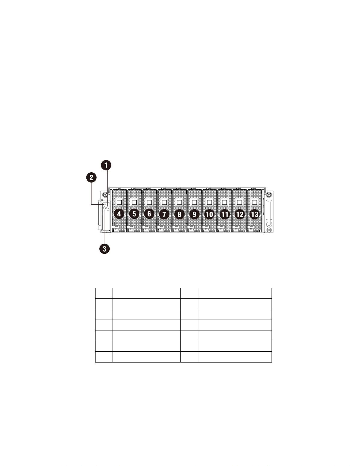
Page 11
1
Power LED/Button
8
PCI Cage 5
2
System LED
9
PCI Cage 6
3
UID LED/Button
10
PCI Cage 7
4
PCI Cage 1
11
PCI Cage 8
5
PCI Cage 2
12
PCI Cage 9
6
PCI Cage 3
13
PCI Cage 10
7
PCI Cage 4
Product Overview
A Tour of the System
The following sections describe the external feat ures of the Dell PowerEdge C410X server.
System Front View
2
Figure 1 – Front View
System Back View
Back view of system is shown below:
Product Overview | 11
Page 12
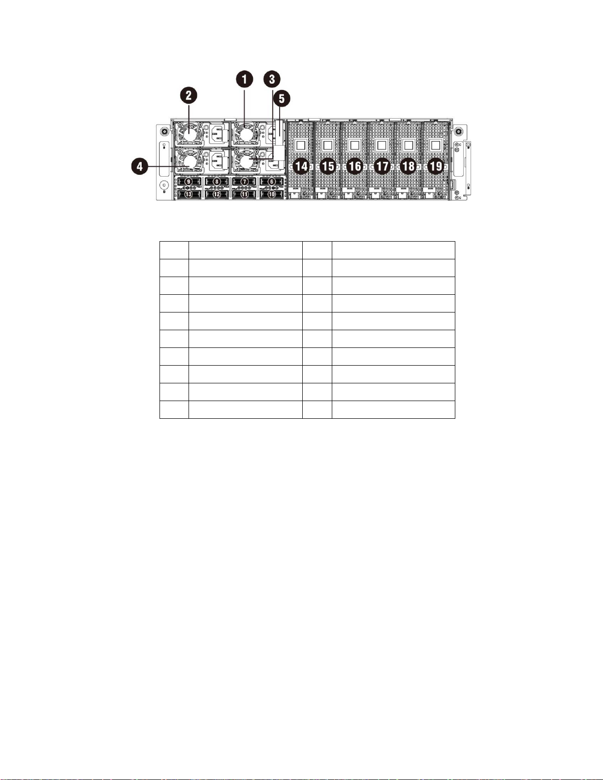
1
Power Module 1
11
iPass connector 6
2
Power Module 2
12
iPass connector 7
3
Power Module 3
13
iPass connector 8
4
Power Module 4
14
PCI Cage 11
5
BMC LAN Cable
15
PCI Cage 12
6
iPass connector 1
16
PCI Cage 13
7
iPass connector 2
17
PCI Cage 14
8
iPass connector 3
18
PCI Cage 15
9
iPass connector 4
19
PCI Cage 16
10
iPass connector 5
Figure 2 – Back View
Product Overview | 12
Page 13
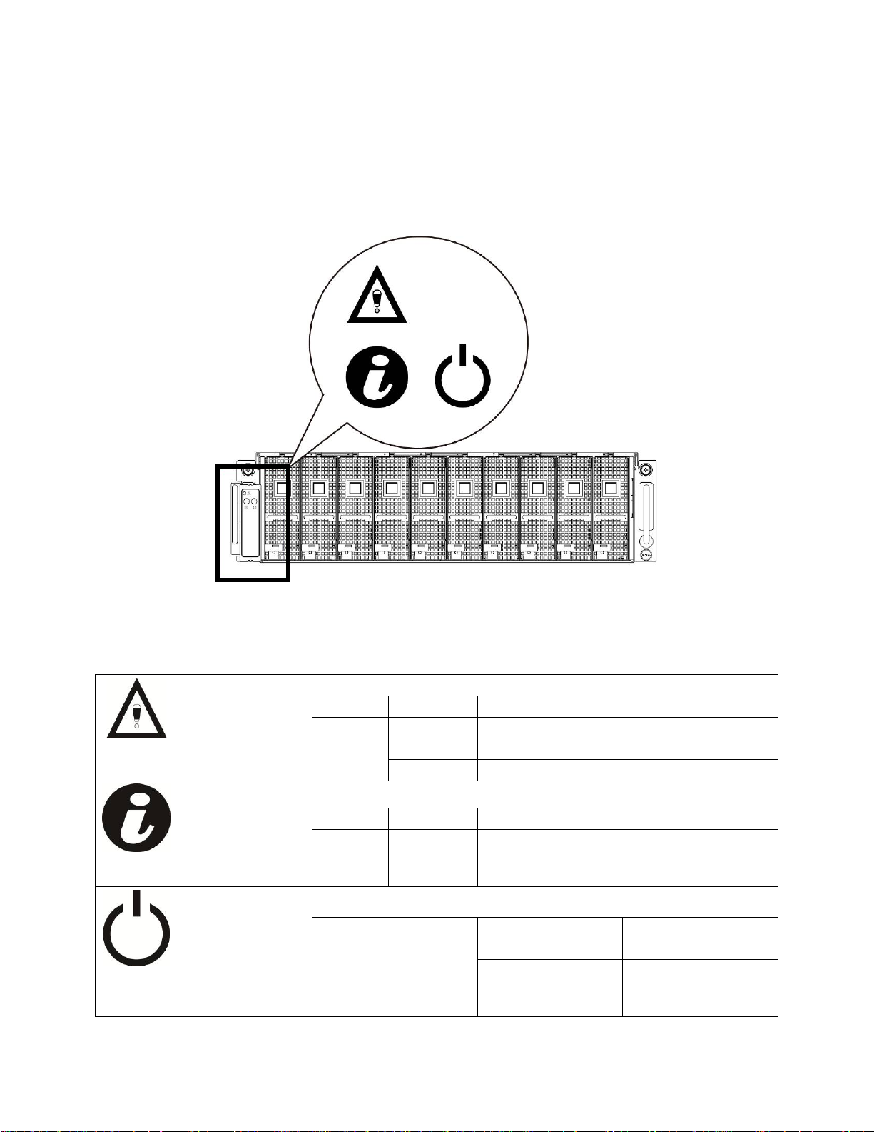
Color
Condition
Occurrence
System LEDs Description
Front System LEDs
The front system LEDs contain System LED, Power LED and UID LED information.
The detailed LEDs information is listed below:
Figure 3 – Front System LEDs
Table 1-1. Front System LEDs
System LED Displays status/errors and is controlled by BMC.
UID LED Lights when front or rear ID button is pressed.
Power LED
Amber Blink Fast Power supply fail
On FAN fail or sensor error
Blink GPU card fail
Color Condition Occurrence
Blue Off No identification
Blinking
Lights green when server is powered on.
Color Condition Occurrence
Green
ID Button pressed on system (ID command
executed)
On Power on
Off Power off
Blinking
Power on fail or without
any GPU card
Product Overview | 13
Page 14

Static / Dynamic IP Switch Function Instruction
To switch from DHCP to static or vice versa:
Hold down the ID button for 5 seconds
While pressing the ID button, press and hold the power button for 5 seconds
Release the power button, and then the ID button
It will take ~30 seconds to change the configuration
The ID light will indicate which mode has been selected:
- Solid for 5 seconds indicates static IP
- Flashing for 5 seconds indicates DHCP
If the default IP address is changed, switching DHCP to static IP will change the IP address back to the
default.
Default IP address is 192.168.0.120
Product Overview | 14
Page 15

3
Removing and Installing Hardware
Safety Measures
CAUTION: Many repairs may only be done by a certified service technician. You should only perform
troubleshooting and simple repairs as authorized in your product documentation, or as direct ed by the
online or telephone service and support team. Damage due t o servicing that is not authori zed by Dell is not
covered by your warranty. Read and follow the safety instructions that came with the product.
CAUTION: Computer components and electronic circuit boards can be damaged by discharges of
static electricity. Working on computers that are still connected to a power supply can be extremely
dangerous. Follow the simple guidelines bel ow to avoid damage to your computer or injury to yourself.
• Always disconnect the computer from the power outlet whenever you are working inside the
computer case.
• If possible, wear a grounded wrist strap when you are working inside the computer case.
Alternatively, discharge any static electricity by touching the bare metal system of the
computer case, or the bare metal body of any other grounded appliance.
• Hold electronic circuit boards by the edges only. Do not touch the components on the board
unless it is necessary to do so. Do not flex or stress the circuit board.
• Leave all components inside the static-proof packaging until y ou are ready to use the
component for the installation.
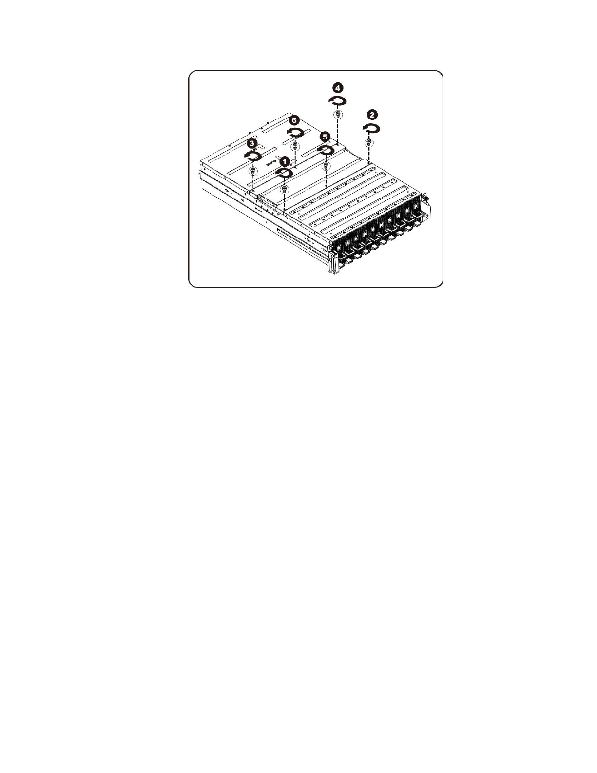
System Cover
Removing System Cover
CAUTION:
Follow these instructions to remove the system cover:
1. Loosen and remove the screws securing the middle cover.
Before you remove or install the system cover: Make sure the system is not
turned on or connected to AC power.
Removing and Installing Hardware | 15
Page 16
Removing and Installing Hardware | 16
Page 17
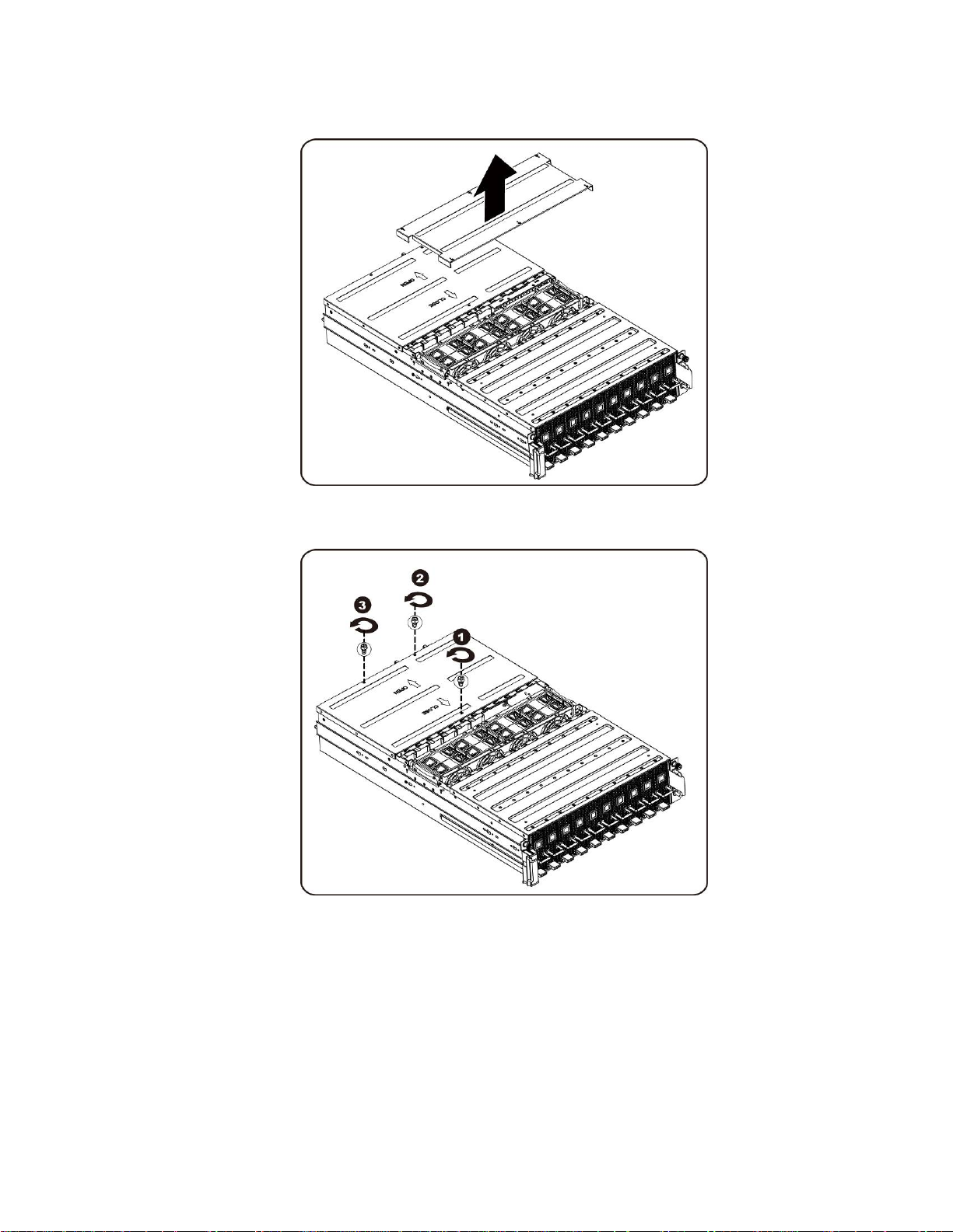
2. Remove the middle top cover from the system.
3. Loosen and remove the screws securing the back cover.
Removing and Installing Hardware | 17
Page 18
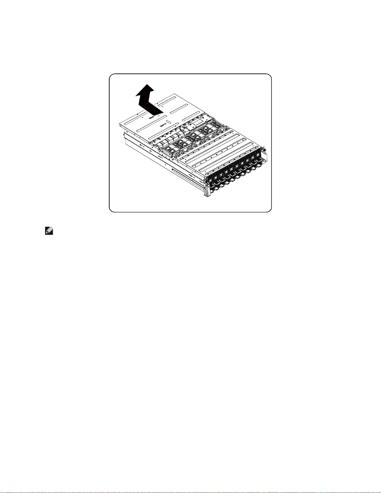
4. Slide the cover horizontally to the back using the traction pad and remove the back cover in
the direction of the arrow.
NOTE:
This system must be operated with the system cover installed to ensure proper cooling.
Installing the system cover
To install the system cover follow the instructions for removing the system cover in the reverse order.
Removing and Installing Hardware | 18
Page 19
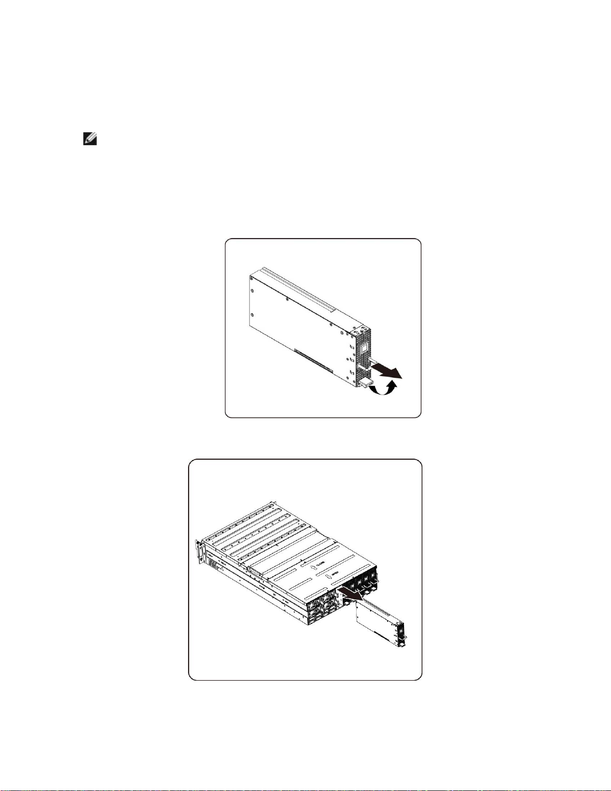
PCI Cage
Removing the PCI Cage
NOTE:
• Take note of the drive tray orientation bef ore sli ding it out.
• The tray will not fit back into the bay if inserted incorrectly.
1. Lift the release lever and pull on the cage handle at the same time.
2. Slide the cage assembly out of the system.
Removing and Installing Hardware | 19
Page 20
Installing the PCI cage
To install the PCI cage follow the instructions for removing the PCI cage in the reverse order.
PCIe Card
Replacing PCIe Card
CAUTION:
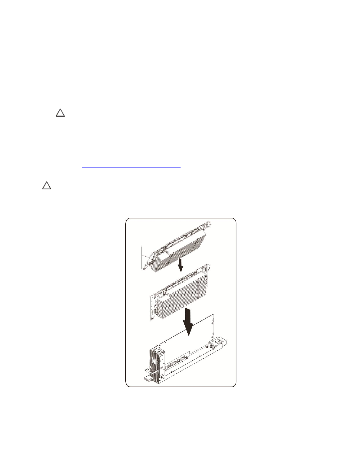
Follow these instructions to replace a PCIE card:
For M1060 Card
1. See to Chapter 4 Cable Routings on pag e 57 to connect switch button cable and PCI power cable.
2. Insert the PCIe card by 45 degree and push it into the socket vertically.
CAUTION: Care should be taken to prev ent damag e t o compone nt s on the ba ck side of t he PCIe card.
Make sure the card does not drag across the card mounting standoffs of the cage when inserting the card
into the socket.
Before you remove or install the PCIe card, press PCI cage power button to
turn off the specific single PCI cage power bef ore replacing PCIe card.
Removing and Installing Hardware | 20
Page 21
3. Secure the card in place with screws and place the PCI side cover as shown in the illustration.
4. Secure the PCI side cover and back cover in place wit h sc rews.
Installing the M1060 card
To install the M1060 card follow the instructions for removing the M1060 card in the reverse order.
Removing and Installing Hardware | 21
Page 22
For M2050/M2070/M2070Q/M2075/M2090 Cards
1. Connect PCI power cable.
2. Insert the PCIe card by 45 degree and push it into the socket vertically.
CAUTION: Care should b e take n to preven t dam age to com ponents on the bac k s ide o f the PCIe card . Make sure the card does
not drag across the card mount i ng st and of fs of the cage when inserting the card into the socket.
3. Secure the card with screw.
4. Attach the support bracket on the PCIE board and secure it in place with 4 screws.
Removing and Installing Hardware | 22
Page 23
5. Connect power cable to card as shown.
6. Replace the side cover.
7. Secure the side cover with 4 screws.
Removing and Installing Hardware | 23
Page 24
8. Secure the PCIE side cover with 3 screws as illustration arro w show.
Removing and Installing Hardware | 24
Page 25
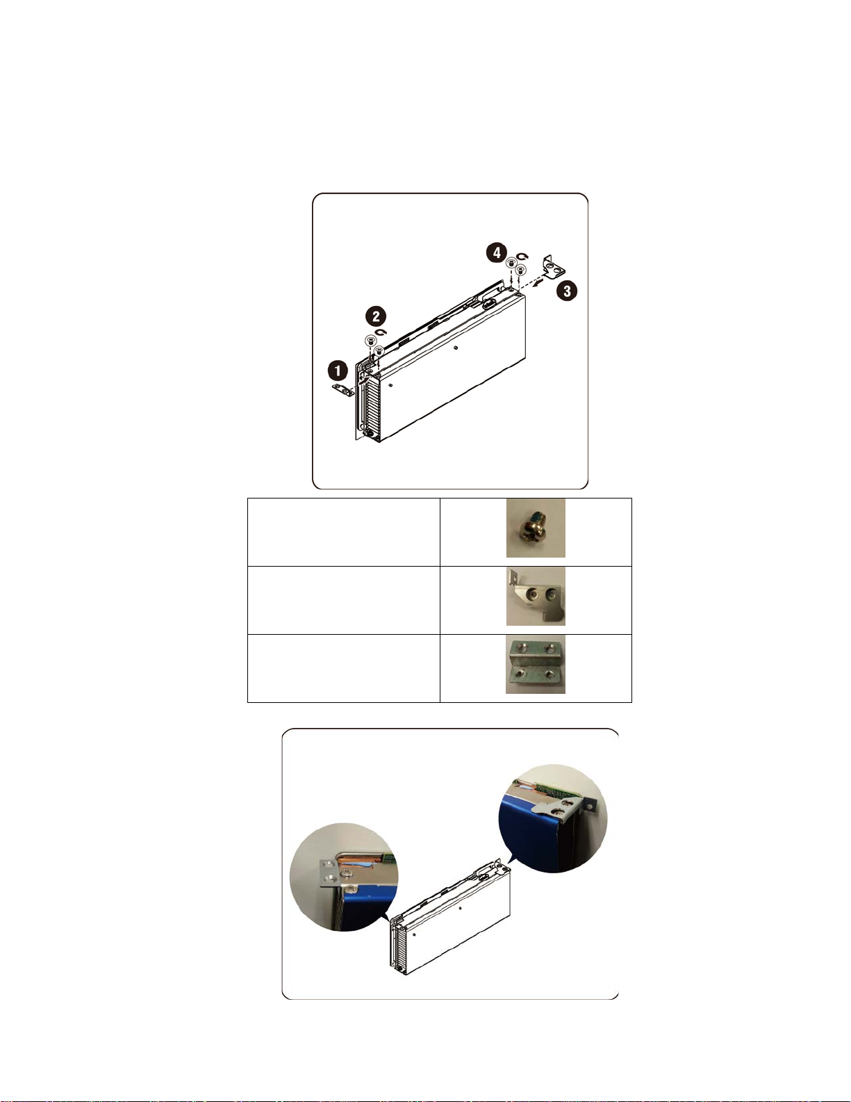
Installing the Intel 5110P Card
Follow the instructions to install the Intel 5110P card.
1. Attach two support brackets with screws to the 5110P card heatsink cover.
Screw 2/4
Support Bracket 3
Support Bracket 1
Removing and Installing Hardware | 25
Page 26

2. Connect power cable to card as shown.
CAUTION: Make sure the power ca ble is plugged before inserting th e PC Ie car d i nt o sock et .
3. Insert the 5110P card into the socket as shown in the illustration.
CAUTION: Care should be taken t o prev ent dam ag e t o c om ponen ts on t he back side of the PCIe card. Make sure the
card does not drag across the card m ount ing s tandoffs of the cage when inserting the card into the sock et .
Removing and Installing Hardware | 26
Page 27
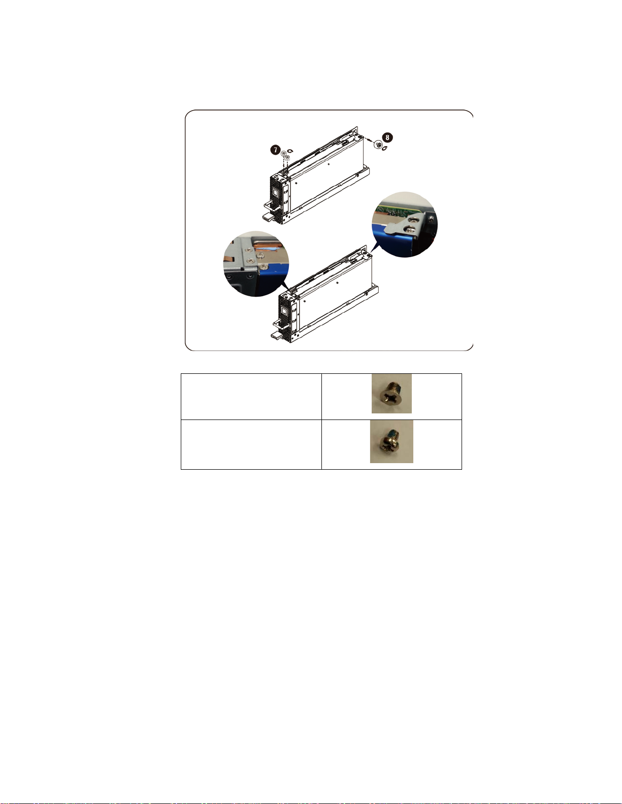
4. Secure the 511P card with 3 screws.
Screw 7
Screw 8
Removing and Installing Hardware | 27
Page 28
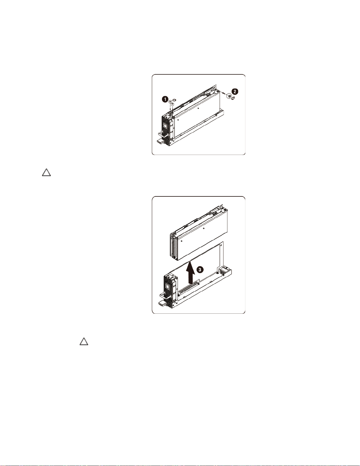
Removing the 5110P card
Follow the instructions to remove the Intel 5110P card.
1. Remove the 3 securing screws.
2. Remove the 5110P card from the socket.
CAUTION: Care should be taken to prevent damage to components on the back side of the PCIe card. Make sure the card does
not drag across the card mount i ng st and of fs of the cage when removing the car d from the socket.
3. Unplug power cable as shown.
CAUTION: Make sure the card is comple tely rem oved from t he socket before unplugging the power cable.
Removing and Installing Hardware | 28
Page 29
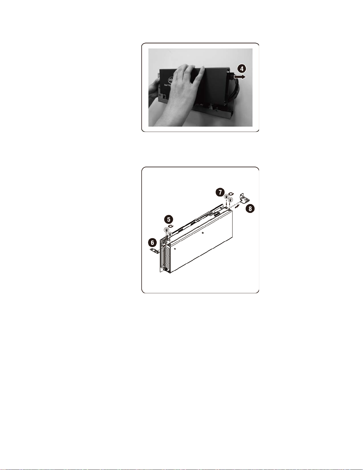
4. Remove the securing screws and the support bracket from the 5110P heatsink cover.
Removing and Installing Hardware | 29
Page 30
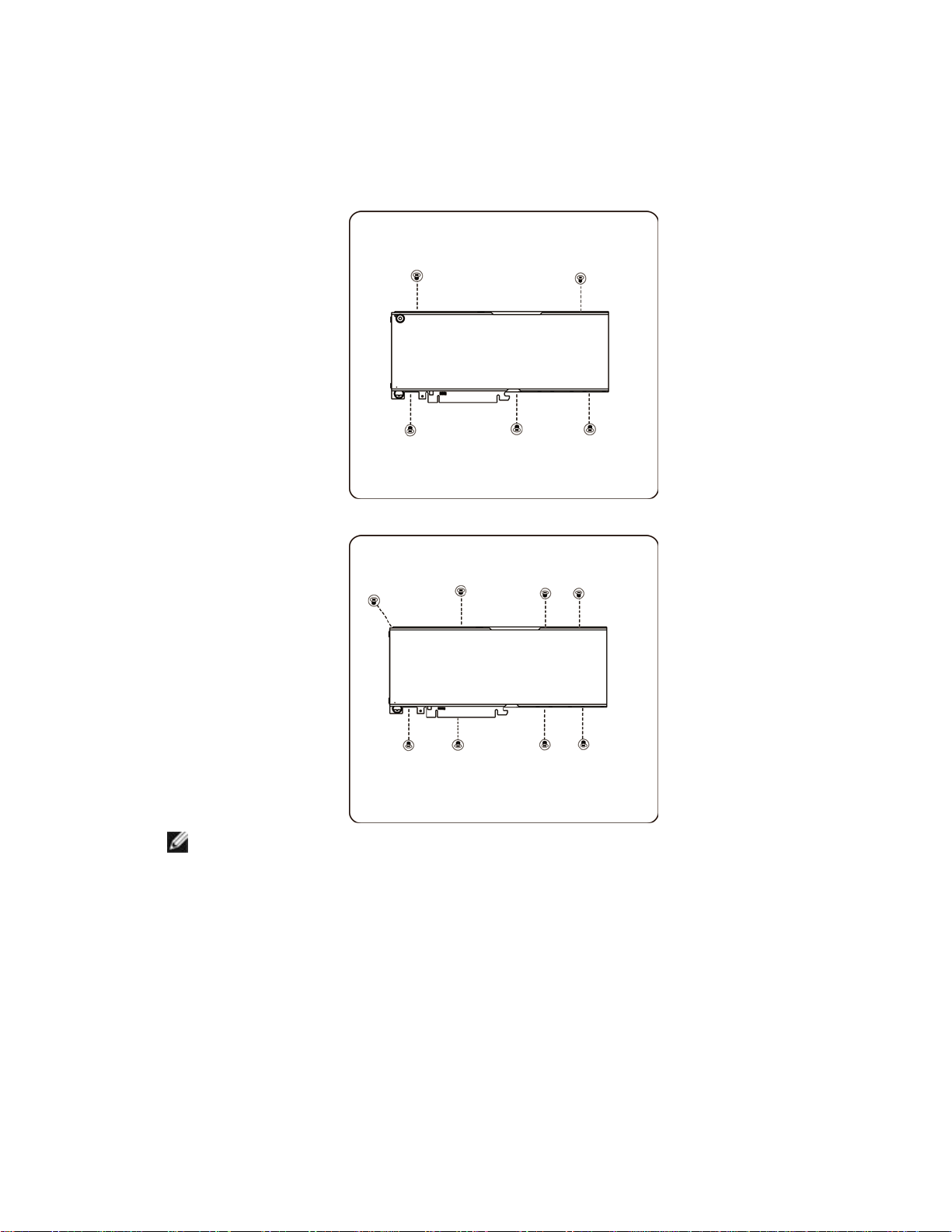
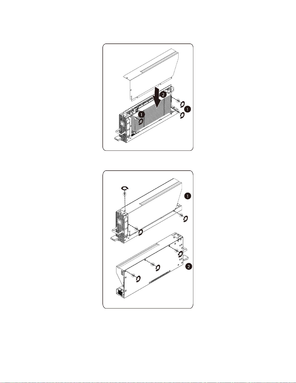
Installing the NVIDIA K10/K20 Card
Follow the instructions to install the NVIDIA K10/K20 card.
1. Remove the 5 securing screws of K10 heatsink top cover.
Remove the 8 securing screws of K20 heatsink top cover.
NOTE: Please keep heatsink top cover and securing screws. The heatsink top cover should
be attached to replaced card before returning.
Removing and Installing Hardware | 30
Page 31

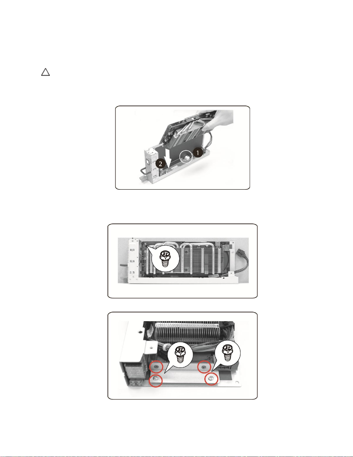
2. Attach the support bracket with two screws to the K10/K20 card.
Screw 2
3. Insert the K10/K20 card into the socket as shown in the illustration.
CAUTION: Care should be taken to prevent damage to components on the back side of the PCIe card. Make sure the card does
not drag across the card mount i ng st and of fs of the cage when inserting the card into the socket.
Removing and Installing Hardware | 31
Page 32

4. Secure the K10/K20 card with 3 screws.
Screw 4
(Same as Screw 2)
Screw 5
Removing and Installing Hardware | 32
Page 33

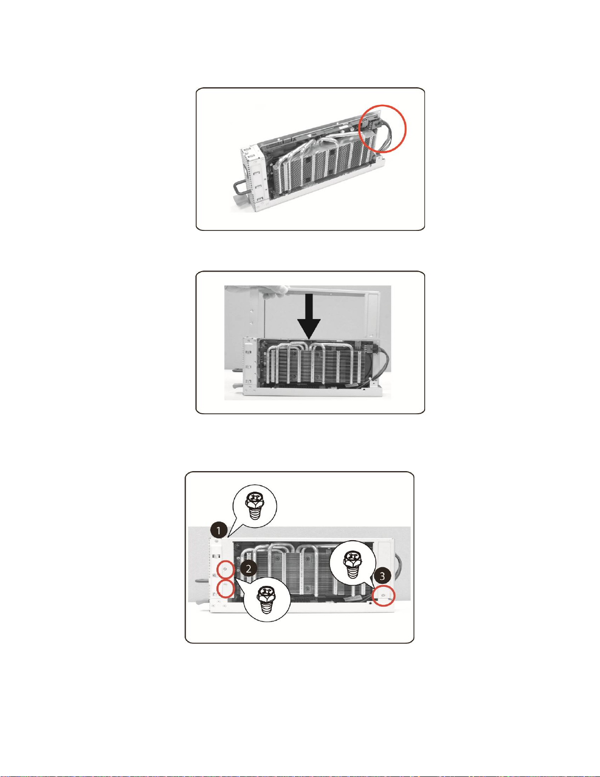
5. Attach K10 support bracket.
NOTE: Use the right mounting holes to secure the mounting b racket for the K10 card.
Attach the K20 support bracket.
NOTE: Use the left mounting holes to secure the mounting br acket for the K20 card.
NOTE: Picture is showing a K10 card for a K20 installation.
Removing and Installing Hardware | 33
Page 34

6. Secure the K10 support bracket with 3 scre ws.
Secure the K20 support bracket with 3 screws.
NOTE: Picture is showing a K10 card for a K20 installation.
Screw 7
(Same as Screw 2)
Screw 8
Removing and Installing Hardware | 34
Page 35

7. Connect power cable to card.
Removing and Installing Hardware | 35
Page 36

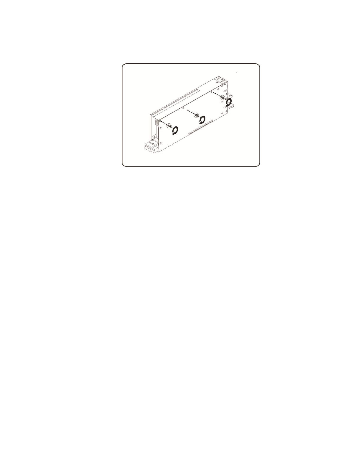
Removing the NVIDIA K10/K20 Card
Follow the instructions to remove the NVIDIA K10/20 card.
1. Unplug power cable as shown.
2. Remove the K10 3 securing screws.
Remove the K20 3 securing screws.
Removing and Installing Hardware | 36
Page 37

3. Remove the K10 support bracket.
Remove the K20 support bracket.
Removing and Installing Hardware | 37
Page 38

4. Remove the 3 securing screws.
5. Remove the card from the socket.
CAUTION: Care should be taken to prevent damage to components on the back side of the PCIe card. Make sure the card does
not drag across the card mount i ng st and of fs of the cage when removing the car d from the socket.
Removing and Installing Hardware | 38
Page 39

6. Remove the securing screws and the support bracket from K10/K20 card.
7. Attach the heatsink top cover to the K10 card and secure with 5 screws.
NOTE: The heatsink top cover must be assembled to the K10 card before it is returned for
replacement.
Removing and Installing Hardware | 39
Page 40

Attach the heatsink top cover to the K20 card and secure with 8 screws.
NOTE: The heatsink top cover must be assembled to the K20 card before it is returned for
replacement.
Removing and Installing Hardware | 40
Page 41

Replacing System Fans
In case of system fan failure, you can quickly replace the system fan.
CAUTION:
Follow the instruction to remove the system fans:
1. Loosen and remove the screws securing the middle cover.
Before you remove or install the system fans, take the steps: 1) Make sure the
system is not turned on or connected to the AC power. 2) Disconnect all
necessary cable connections. Failure to observe these warnings could res ult in
personal injury or damage to the equipment.
Removing and Installing Hardware | 41
Page 42

2. Remove the middle top cover from the system.
3. Lift the system fan ears.
Removing and Installing Hardware | 42
Page 43

4. Lift the system fan out of the system fan cage.
Installing the system fans
To install the system fans follow the instructions for removing the system fans in the reverse order.
Removing and Installing Hardware | 43
Page 44

Fan cage
Replacing System Fan Cage
CAUTION:
1. Loosen and remove the screws securing the m i ddl e cover.
Before you remove or install the system fan cage, take the steps: 1) Make
sure the system is not turned on or connected to the AC power. 2) Disconnect
all necessary cable connections. Failure to observe these warnings could
result in personal injury or damage to the equipment.
Removing and Installing Hardware | 44
Page 45

2. Remove the middle top cover from the system.
3. Loosen and remove the screws securing the fan cage.
Removing and Installing Hardware | 45
Page 46

4. Lift the fan cage out of the system.
NOTE: Watch the fan status LED cables a s the fan c age is lifted out of the system. The fan s tatus LED
connector should be unplugged befor e removing the fan cage completely from the system.
Removing and Installing Hardware | 46
Page 47

5. Remove the fans from the fan cage.
Removing and Installing Hardware | 47
Page 48

6. Loosen and remove the screws on top of the system fan cage.
Installing the system fan cage
To install the system fan cage follow the instructions for removing the system fan cage in the reverse order.
Removing and Installing Hardware | 48
Page 49

Power supply
Replacing Power Supplies
In case of a power supply failure, you can quickly replace the power supply unit.
Follow these instructions to remove the power supply:
CAUTION:
1. Pull up the power supply handle.
In order to reduce the risk of injury from electric shock, disconnect AC power
from the power supply before removing it from the system.
Removing and Installing Hardware | 49
Page 50

2. Press the retaining clip on the right side of the power supply along the direction of the arrow.
3. At the same time, pull out the power supply by using its han dl e.
NOTE: It takes considerable force to remove the power supply.
Removing and Installing Hardware | 50
Page 51

Follow these instructions to install the power supply:
Insert the replacement power supply firm l y into the bay. The retaining clip should snap. Fold the power
supply handle down. Connect the AC power cord to the replaced power supply.
Removing and Installing Hardware | 51
Page 52

Power Distribution Board (PDB)
Replacing Power Distribution Board (PDB)
Follow these instructions to remove the PDB:
CAUTION:
1. Remove al l power supplies from the system following the steps outlined in Section
Power supplies.
2. Loosen and remove the screws securing the middle cover.
Before you remove or install the power distributi on board take the steps: 1)
Make sure the system is not turned on or connected to the AC power. 2)
Disconnect all necessary cable connections. F ail ure to observe these
warnings could result in personal injury or damage to the equipment.
-Replacing
Removing and Installing Hardware | 52
Page 53

3. Remove the middle top cover from the system.
4. Loosen and remove the screws securing the back cover.
Removing and Installing Hardware | 53
Page 54

5. Slide the cover horizontally to the back using the traction pad and remove the back cover in
the direction of the arrow.
6. Then Remove the BMC LAN cable from the retention clip. Lay the BMC LAN cable across the
fans out of the way.
Removing and Installing Hardware | 54
Page 55

7. Loosen and remove the screws securing the power suppl y cage.
8. Slide the power cage horizontally to the back.
Removing and Installing Hardware | 55
Page 56

9. Lift the power cage to remove it in the direction of the arr ow.
10. Loosen and remove the screw securing the rail.
Removing and Installing Hardware | 56
Page 57

11. Remove the rail by lifting the retention clip and at the same time slide the rail in the direction of
the arrow.
12. Loosen and remove the screws securing the PDB.
Removing and Installing Hardware | 57
Page 58

13. Remove the PDB in the direction of the arrow.
NOTE: It takes considerable force to remove the PDB.
Installing the power distribution board
To install the power distribution board follow the instructions for removing the power distribution board in
the reverse order.
.
Removing and Installing Hardware | 58
Page 59

iPass Board
Replacing iPass Board
Follow these instructions to replace the iPass board:
CAUTION:
1. Loosen and remove the screws securing the middle cover.
Before you remove or install the iPass Board, take the steps: 1) Make sure the
system is not turned on or connected to the AC power.2) Disconnect all
necessary cable connections. Failure to observ e these warnings could result
in personal injury or damage to the equipment.
Removing and Installing Hardware | 59
Page 60

2. Remove the middle top cover from the system.
3. Loosen and remove the screws securing the back cover.
Removing and Installing Hardware | 60
Page 61

4. Slide the cover horizontally to the back using the traction pad and remove the back cover in
the direction of the arrow.
5. Then R em ove the BMC LAN cable from the retention clip. Lay the BMC LAN cable across the
fans out of the way.
Removing and Installing Hardware | 61
Page 62

6. Pull up the power supply handle.
7. Remove the power supply in the direction of the arrow.
Removing and Installing Hardware | 62
Page 63

8. Loosen and remove the screws securing the power suppl y cage.
9. Slide the power cage horizontally to the back.
Removing and Installing Hardware | 63
Page 64

10. Lift the power cage to remove it in the direction of the arrow.
11. Loosen and remove the screws securing the top of the iPass connector cage.
Removing and Installing Hardware | 64
Page 65

12. Slide the iPass connector cage horizontally to the back.
13. Loosen and remove the screws securing the top iPass board.
Removing and Installing Hardware | 65
Page 66

14. Lift up the iPass board and remove it from the system.
15. Loosen and remove the screws securing the bottom iPass board.
Removing and Installing Hardware | 66
Page 67

16. Lift up the iPass board and remove it from the system.
Installing the iPass board
To install the iPass board follow the instructions for removing the iPass board in the reverse order.
Removing and Installing Hardware | 67
Page 68

Middle Board
Replacing Middle Board
Follow these instructions to replace the middle board:
CAUTION:
1. Remove the F an Cage. See Section- Replacing Fan Cage
2. Remove the Power Distribution Board. See Section-Replacing Power Distribution Board
3. Remove the iPass board. See Section-Replacing iPas s B oard.
4. Remove the fourteen (14) screws securing the m i ddl e board in place.
Before you remove or install the middle board, t ake the steps: 1) Make sure
the system is not turned on or connected to t he A C power. 2) Disc onnect all
necessary cable connections. Failure to observ e these warnings could result
in personal injury or damage to the equipment.
.
Removing and Installing Hardware | 68
Page 69

5. Lift the middle board out of the system in the direction of the arrow, front edge first , to clear
the IO ports.
Installing the system middle board
To install the system middle board follow the instructions for removing the system middle board in the
reverse order.
Removing and Installing Hardware | 69
Page 70

Front I/O Panel
Removing Front I/O Panel
CAUTION:
1. Remove the screws securing the Front I/O panel c over.
Before you remove or install the Front I/O Panel, mak e sur e the system is
not turned on or connected to the AC power.
2. Remove the Front I/O panel cover.
Removing and Installing Hardware | 70
Page 71

3. Remove the sc rews secu ring the Front I/O panel.
4. Remove the Front I/O panel and disconnect the cable.
Installing the Front IO panel
To install the Front IO panel follow the instructions for removing the Front IO panel in the reverse order.
Removing and Installing Hardware | 71
Page 72

Installing the Rail and the System
Follow these instructions to install the rail i nto a rack:
1. Instal l the sliding rails into the rack.
2. Align the inner rails with the sliding rails of the rack.
Removing and Installing Hardware | 72
Page 73

3. Push the system into the sliding rails until the locki ng latch clicks into place.
4. Connect ipass connectors and power connectors.
Removing and Installing Hardware | 73
Page 74

NOTE: The 1400W Power Supplies requ ire 220VAC.
Removing and Installing Hardware | 74
Page 75

1
Fan Power Cable
2
Front I/O Cable
3
BMC LAN Cable
4
Fan LED Cable
5
PCI Power Cable
6
Switch Cable
Cable Routings
4
Cable Routings | 75
Page 76

2 to 1 mode
4 to 1 mode
8 to 1 mode
IPASS
PCIE
IPASS PCIE
IPASS
PCIE
Mapping1
1
VS
1,15
1
VS
1,2,15,16
1
VS
1,2,3,4,13,14,15,16
5
2,16 5 N/A 5 N/A
Mapping2
2
VS
3,13
2
VS
3,4,13,14
2 VS
N/A
6
4,14 6 N/A 6 N/A
Mapping3
3
VS
5,11
3
VS
5,6,11,12
3
VS
5,6,7,8,9,10,11,12
7
6,12 7 N/A 7 N/A
Mapping4
4
VS
7,9
4
VS
7,8,9,10
4 VS
N/A
8
8,10 8 N/A 8 N/A
iPass Port Mapping
NOTE: The default port mapping is 2 to 1 m ode.
Cable Routings | 76
Page 77

5
BMC Remote Management Console
This chapter provides information on the various functions of the Dell Remot e Management Console GUI’ s
(Graphics User Interface).
Initial Configuration using a DHCP Server
Before entering the Dell Remote Management Console, you need to connect the DHCP server in the
subnet to which it is physically connected. If a DHCP server is found, it may provide a valid IP address,
gateway address and net mask. Before you connect the device to your local subnet, be sure to complete
the corresponding configuration of your DHCP server. It is recommended to configure a fixed IP
assignment to the MAC address of the system.
BMC Remote Management Console | 77
Page 78

Static/DHCP IP Controlled by Front Panel Button
To switch from DHCP to static or vice versa:
Hold down the ID button for 5 seconds
While pressing the ID button, press and hold the power button for 5 seconds
Release the power button, and then the ID button
It will take ~30 seconds to change the configuration
The ID light will indicate which mode has been selected:
- Solid for 5 seconds indicates static IP
- Flashing for 5 seconds indicates DHCP
If the default IP address is changed, switching DHCP to static IP will change the IP address back to the
default.
The default IP address is 192.168.0.120
BMC Remote Management Console | 78
Page 79

Remote Management Console Overview
1. Open a web browser and type in your identified IP. The IP address can be found using your DHCP
server.
2. A dialog box prompts you to enter Username and Password.
3. Enter the following values:
Username: root
Password: root
NOTE: The default user name and password are in lower-case ch a ra ct er s.
NOTE: When you log in using the root user name and password, you have full administrative
privileges. It is advised that once you log in, you should change the root password.
NOTE: Password cannot be reset to default and midplane replacement is required if password is
missing.
BMC Remote Management Console | 79
Page 80

Enter Dell Remote Management Console
After you successfully log in to your Dell Remote Management Console, the Remote Management
Console GUI appears.
Properties
Properties displays the firmware version of current remote client system.
BMC Remote Management Console | 80
Page 81

Configuration
Network
You can view and modify the network settings on this screen. Select whether to obtain an IP address
automatically or configure one manually. It is recomme nded to use DHCP if your environ ment has a DHCP
server. You can set DHCP (obtain the IP address automatically) or STATIC IP (configure the IP address
manually). When you finish configuration, click Apply Changes or for re-configuration click Refresh.
BMC Remote Management Console | 81
Page 82

Security
Security shows the current certificate status. To generate a new certificate, click Generate Certi fica te.
To upload a certificate, click Upload Certificate.
BMC Remote Management Console | 82
Page 83

Users
To configure a specific user, click the Users ID. To display new user informat i on, click Refresh.
Please note that BMC convention for enabling an 'anonymous' login is to configure the entry for User ID 1
with a null username (all zero’s) and a null password (all zero’s). Applications may then present this to the
user as an anonymous login.
BMC Remote Management Console | 83
Page 84

Services
You can configure the web server parameters (such as, HTTP Port Number, HTTPS Port Number , and
Timeout) on a remote computer. By def aul t, the t ime out is 1800 s econd s; 5 f or t he Max Se ssions and 1 fo r
the Active Sessions.
When you finish the configuration, click Apply Changes.
BMC Remote Management Console | 84
Page 85

User
This may be considered the lowest privilege level .
Operator
All BMC commands are allowed, except for configuration commands that
band interfaces. For example,
Operator privilege does not allow the capability to disable individual
Administrator
All BMC commands are allowed, including configuration commands. An
Administrator can even execute configuration commands that would
IPMI
This screen contains two sections: IPMI Serial and IPMI Settings.
IPMI Serial
There are three serial configuration in IPMI Serial: Connection Mode Settings, Baud Rate, and Channel
Privilege Level Limit.
The Connection Mode Settings allows user to select the Console redirection type and to manage the
system from a remote location.
Once the connection mode is set, select the Baud Rate from the drop-down list.
With Channel Privilege Level Limit, users can be configure d to operate wit h a particular m aximum Privi lege
Level. Privilege level s tell the BMC whi ch commands are allowed t o be executed. Table 3 lists the currently
defined User Privilege Levels.
Table 5-1. User Privilege Levels
can change the behavior of the out-ofchannels, or change user access privileges.
disable the channel that the Administrator is comm unicating over.
BMC Remote Management Console | 85
Page 86

IPMI Settings
IPMI Settings provides remote configurati on over LAN. To activate IPMI remote configuration by LAN,
check Enable IPMI Over LAN option, define the Channel Privilege Level Limi t, and enter the Encryption
Key.
When you finish the configuration, click Apply Changes.
BMC Remote Management Console | 86
Page 87

Sessions
This screen displays information on Active Sessions. Additionally, the trash can icon provides the delete
function for privileged users. Click Refresh to refresh the Sessions status.
BMC Remote Management Console | 87
Page 88

Updates
The firmware can be updated remotely.
To update firmware, follow the instruction below:
1. Select the file on your local system using Browse.
2. Select Update Ty pe.
3. Select Preserve Configuration.
4. Click Update to delete the current version and update to the new version.
NOTE: BMC firmware update should not be interrupted, any i nterruption may result unrecoverable
firmware crash? ROM replacement is require d to bring C410x back. (firmware upgrade time: around 8
minutes)
BMC Remote Management Console | 88
Page 89

Utilities
Utilities provides BMC reboot and Factory default restore functions.
To reboot system, click Reboot.
To restore factory default, click Factory Default.
BMC Remote Management Console | 89
Page 90

Server Information
Power Control
The Power Control allows you to power on/off/cycle the remote host system. Additionally you can see the
remote power status.
To perform the power control operation, select the operation and click Apply Changes.
BMC Remote Management Console | 90
Page 91

Power Consumption
This screen displays information on the system power consumption. The information includes Current
Power Consumption, Power Consumption Monitoring Start Date, Max/Min Power Consumption, and
Average Power Consumption.
BMC Remote Management Console | 91
Page 92

The green color indicates the device is healthy and there’s no sensor that has any alert.
The yellow color indicates the device has at least one sensor that has warning alert.
The red color indicates the device has at least one sensor that has a critical alert.
GPU Power Consumption
This screen displays the status of GPU power consumption.
Each sensor displays different color to indicate t he health status of a specified GPU device.
BMC Remote Management Console | 92
Page 93

The green color indicates the device is healthy and there’s no sensor that has any alert.
The yellow color indicates the device has at least one sensor that has a warning alert.
The red color indicates the device has at least one s ensor that has a critical alert.
Thermal
This screen displays the Fans and Temperatures sensors of a remote host system.
Click Refresh to update current health status for both Fans and Temperatures.
Fans
Temperatures
BMC Remote Management Console | 93
Page 94

System Event Log
System Event Log: It records the event when sensor has an abnormal state. When the log matches the
pre-defined alert, the system sends out the notification automatically, if it is pre-configured.
BMC Remote Management Console | 94
Page 95

Platform Events
A platform event filter (PEF) can trigger an action and generate an alert when a critical hardware-related
event occurs. For each PEF, you can choose the action to be taken when a platform event occurs. You
can also choose to generate and send an alert when a platform event occurs.
In the Platform Events screen, you can enable the generation of platform event alerts globally by cli cking
Global Alerting Enable.
When you finish the configuration, click Apply Changes.
BMC Remote Management Console | 95
Page 96

Traps Settings
In the Trap Settings, user can set the IPv 4 and Ipv6 Destination List.
IPv6 and IPv4 are two completely separate protocols. IPv6 is not backwards compatible with IPv4, and
IPv4 hosts and routers will not be able to deal dire ct l y with IPv6 traffic.
IPv6 has a significantly larger address space than IPv4. This results from the use of a 128-bit address,
whereas IPv4 uses only 32 bits.
When you finish the configuration, click Apply Changes.
BMC Remote Management Console | 96
Page 97

Email Settings
If you want the alert to be sent by email, you can configure to specify the e-mail address, subject and
message in the Email Settings. After y ou finish the configuration, click Apply Change to save the sett ings.
BMC Remote Management Console | 97
Page 98

Port Map
User can identify the specified iPASS mapping to PCIE controller in Port Map. Click Apply Change to
save the settings.
BMC Remote Management Console | 98
Page 99

Light green:
Power On
6
T roubleshooting Your System
Safety First—For You and Your System
WARNING: Whenever you need to l ift the s ystem, get ot hers to as sist you. T o avoid inj ury, do not att empt to lif t
the system by yourself.
CAUTION: Before removing the system cover, turn off all power, then unplug the AC power cord, and then
disconnect all peripherals, and all LAN lines.
CAUTION: Many repairs may only be done by a certified service technician. You should only perform
troubleshooting and simple repairs as authorized in your product documentation, or as directed by the online or
telephone service and support t eam. Damage due to servicing that is not aut horized by Dell is not covered by your
warranty. Read and follow the safety instructions that came with the product.
Symptom: iPass card / port not recognized by the system
Check System Status (System must stay switched off)
3. Look at the back of each power supply. A green LED should be lit when AC power is applied.
NOTE: Do not press power button on the system.
4. Check front panel LED (UID and Power LED). See figure 1 on Page 10
ID and Power LED should not light at the beginning.
After 30 seconds or so, when BMC is ready, UID LED and P ower LED blink once.
5. System power on and Power LED lights. Other PCIe devices will be powered on in 40 sec.
PCIe device
6. When PCIe cards are ready, power on the host system for test.
Troubleshooting Your System | 99
Page 100

Checking GPU Card
1. Power off and remove the middle cover. See section-Removing System Cover to remove the middle
cover.
2. Powe r on the system and PCIe device and check if the GPU card LED lights.
3. If not, see Check iPass cable.
Checking iPass Cable
1. Check if iPass cable is properly connected.
2. If the iPass cable is not plugged in correctly, power off the sytem and plug-in the iPass cable again.
3. If not, swap iPass cable.
Troubleshooting Your System | 100
 Loading...