

Dell PowerEdge C1100 User Manual [en, ru, de, es, fr, cs, pl]

Dell™ PowerEdge™ C1100
Getting Started
With Your System
Začínáme se systémem
Guide de mise en route
Handbuch zum Einstieg mit dem System
Τα πρώτα βήµατα µε το σύστηµά σας
Rozpoczęcie pracy z systemem
Начало работы с системой
Procedimientos iniciales con el sistema
תכרעמה םע הדובעה תליחת


Dell™ PowerEdge™ C1100
Getting Started
With Your System
Regulatory Model CS24-TY
Notes, Cautions, and Warnings
NOTE: A NOTE indicates important information that helps you make better use of
your computer.
CAUTION: A CAUTION indicates potential damage to hardware or loss of data
if instructions are not followed.
WARNING: A WARNING indicates a potential for property damage, personal
injury, or death.
____________________
Information in this document is subject to change without notice.
© 2010 Dell Inc. All rights reserved.
Reproduction of these materials in any manner whatsoever without the written permission of Dell Inc.
is strictly forbidden.
Trademarks used in this text: Dell, the DELL logo, and PowerEdge, are trademarks of Dell Inc.;
Citrix and XenServer are trademarks of Citrix Systems, Inc. and/or more of its subsidiaries, and may
be registered in the United States Patent and Trademark Office and in other countries; Intel and Xeon
are registered trademarks of Intel Corporation in the U.S. and other countries; VMware is a registered
trademark of VMware, Inc. in the United States and/or other jurisdictions; Red Hat and Red Hat
Enterprise Linux are registered trademarks of Red Hat, Inc. in the United States and other countries;
SUSE is a registered trademark of Novell, Inc. in the United States and other countries.
Other trademarks and trade names may be used in this document to refer to either the entities claiming
the marks and names or their products. Dell Inc. disclaims any proprietary interest in trademarks and
trade names other than its own.
Regulatory Model CS24-TY
February 2010 P/N 6WK8G Rev. A00

Installation and Configuration
WARNING: Before performing the following procedure, review the safety
instructions that came with the system.
Unpacking the System
Unpack your system and identify each item.
Installing the Tooled Rail Solution
WARNING: Whenever you need to lift the system, get others to assist you.
To avoid injury, do not attempt to lift the system by yourself.
WARNING: The system is not fixed to the rack or mounted on the rails. To avoid
personal injury or damage to the system, you must adequately support the system
rack during installation and removal.
CAUTION: Before installing systems in a rack, install front and side stabilizers
on stand-alone (single) racks or the front stabilizer on racks joined to other racks.
Failure to install stabilizers accordingly before installing systems in a rack could
cause the rack to tip over, potentially resulting in bodily injury under certain
circumstances. Therefore, always install the stabilizer(s) before installing
components in the rack.
CAUTION: Many repairs may only be done by a certified service technician.
You should only perform troubleshooting and simple repairs as authorized in your
product documentation, or as directed by the online or telephone service and
support team. Damage due to servicing that is not authorized by Dell is not
covered by your warranty. Read and follow the safety instructions that came
with the product.
Getting Started With Your System 3

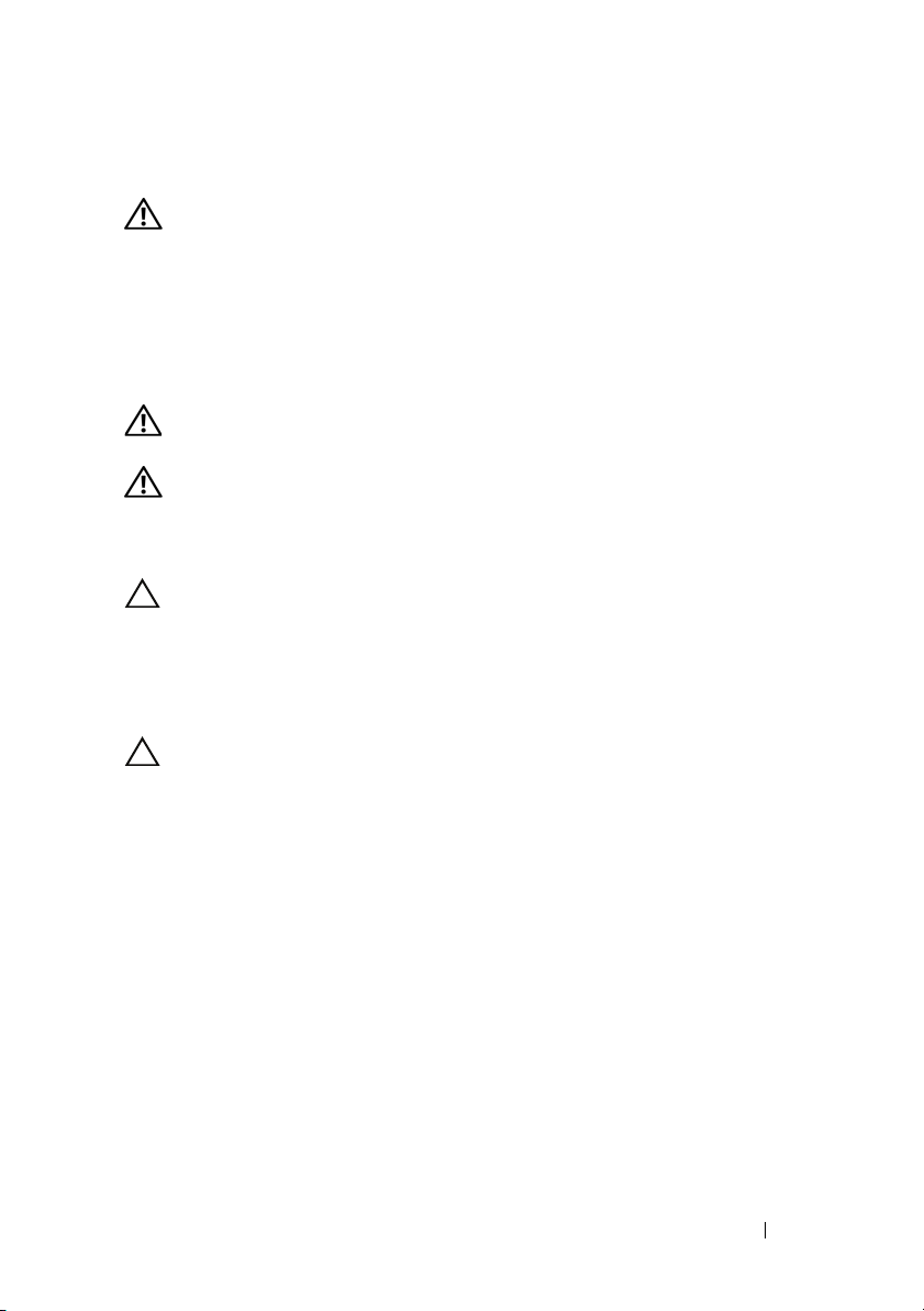
1
Install the sliding rails into the rack.
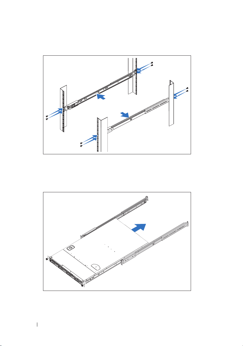
2
Align the inner rails with the sliding rails of the rack and push the system
into the sliding rails until the locking latch clicks into place.
4 Getting Started With Your System

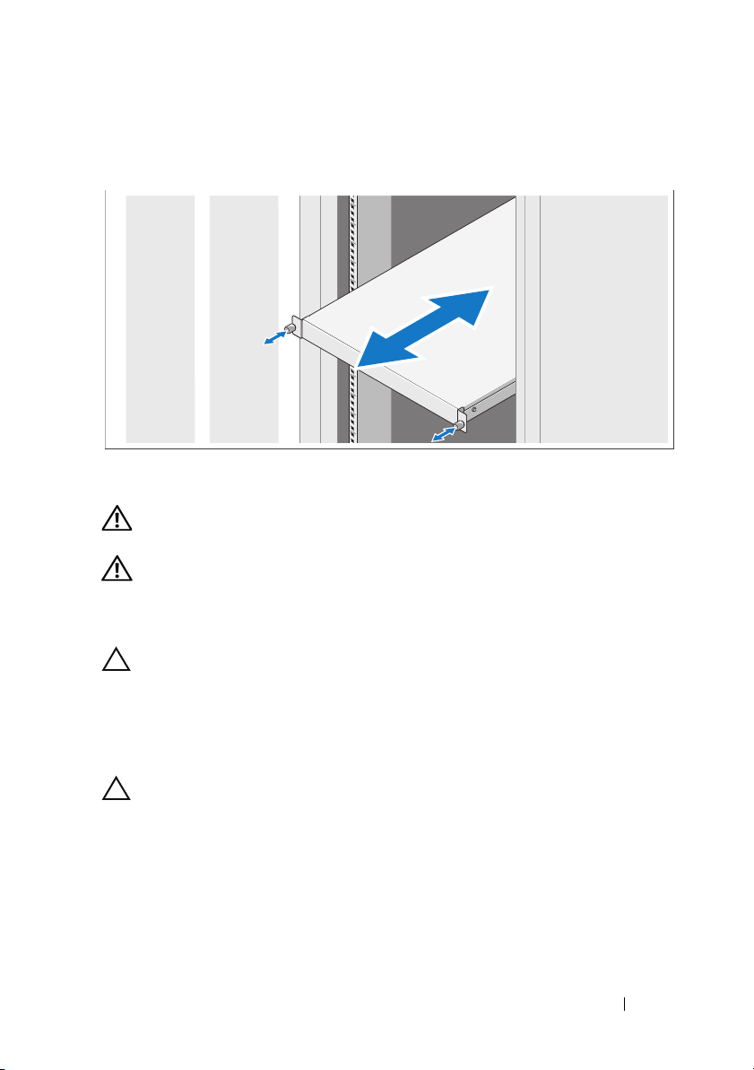
3
Slide the system into the rack and tighten the thumbscrews to secure the
ears of system to the front of the rack.
Installing the Tool-less Rail Solution
WARNING: Whenever you need to lift the system, get others to assist you.
To avoid injury, do not attempt to lift the system by yourself.
WARNING: The system is not fixed to the rack or mounted on the rails. To avoid
personal injury or damage to the system, you must adequately support the system
rack during installation and removal.
CAUTION: Before installing systems in a rack, install front and side stabilizers
on stand-alone (single) racks or the front stabilizer on racks joined to other racks.
Failure to install stabilizers accordingly before installing systems in a rack
could cause the rack to tip over, potentially resulting in bodily injury under certain
circumstances. Therefore, always install the stabilizer(s) before installing
components in the rack.
CAUTION: When installing rails in a square-hole rack it is important to ensure
that the square peg slides through the square holes.
Getting Started With Your System 5
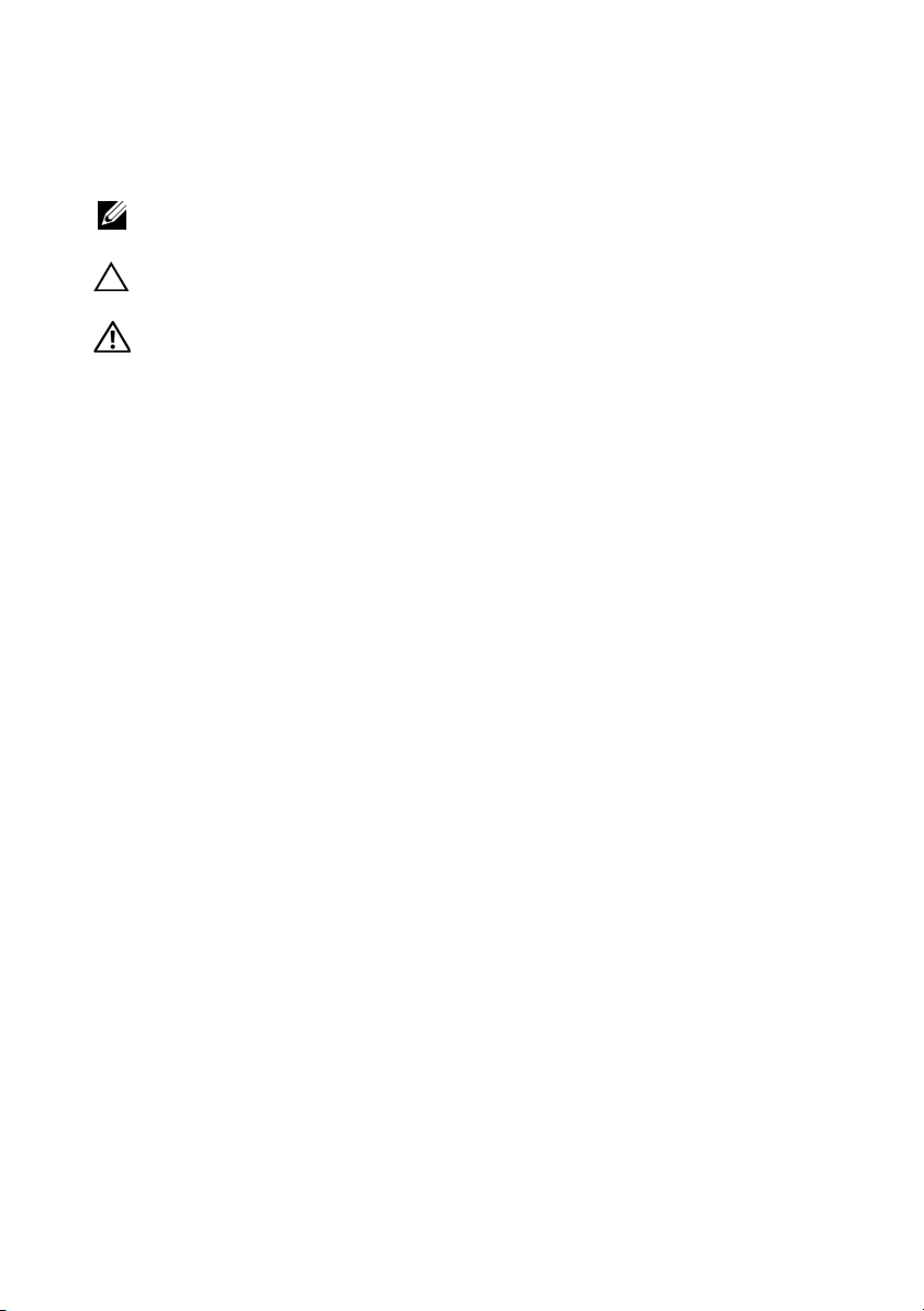
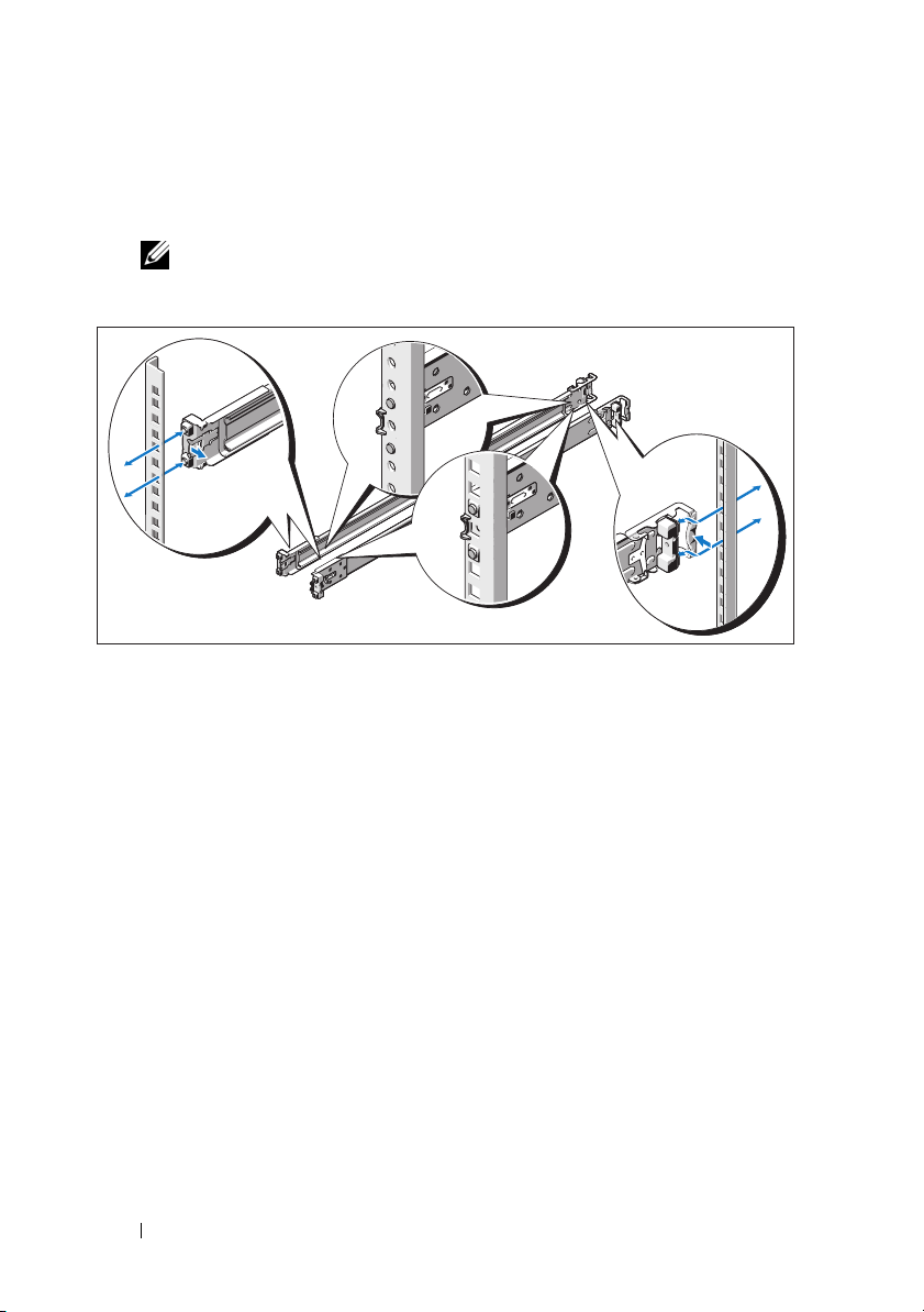
1
Align the end pieces of the rails on the vertical rack flanges to seat the
pegs in the bottom hole of the first U and the top hole of the second U,
and engage the back end of the rail until the latch locks in place.
NOTE: The rails can be used in both square- and round-hole racks.
2
Repeat these steps to position and seat the front end piece on
the vertical flange.
3
To remove the rails, pull on the latch release button on the end piece
midpoint and unseat each rail.
6 Getting Started With Your System
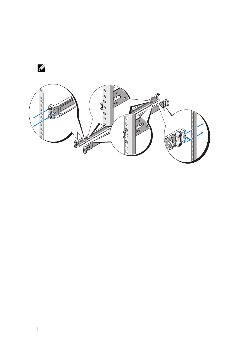
4
Align the four keyhole slots on the chassis rails with the corresponding pins
on the system and slide the chassis rails towards the back of the system
until it locks into place.
5
Align and insert the ends of the chassis rails into the ends of the rails and
push the system inward until the chassis rails lock into place.
Getting Started With Your System 7

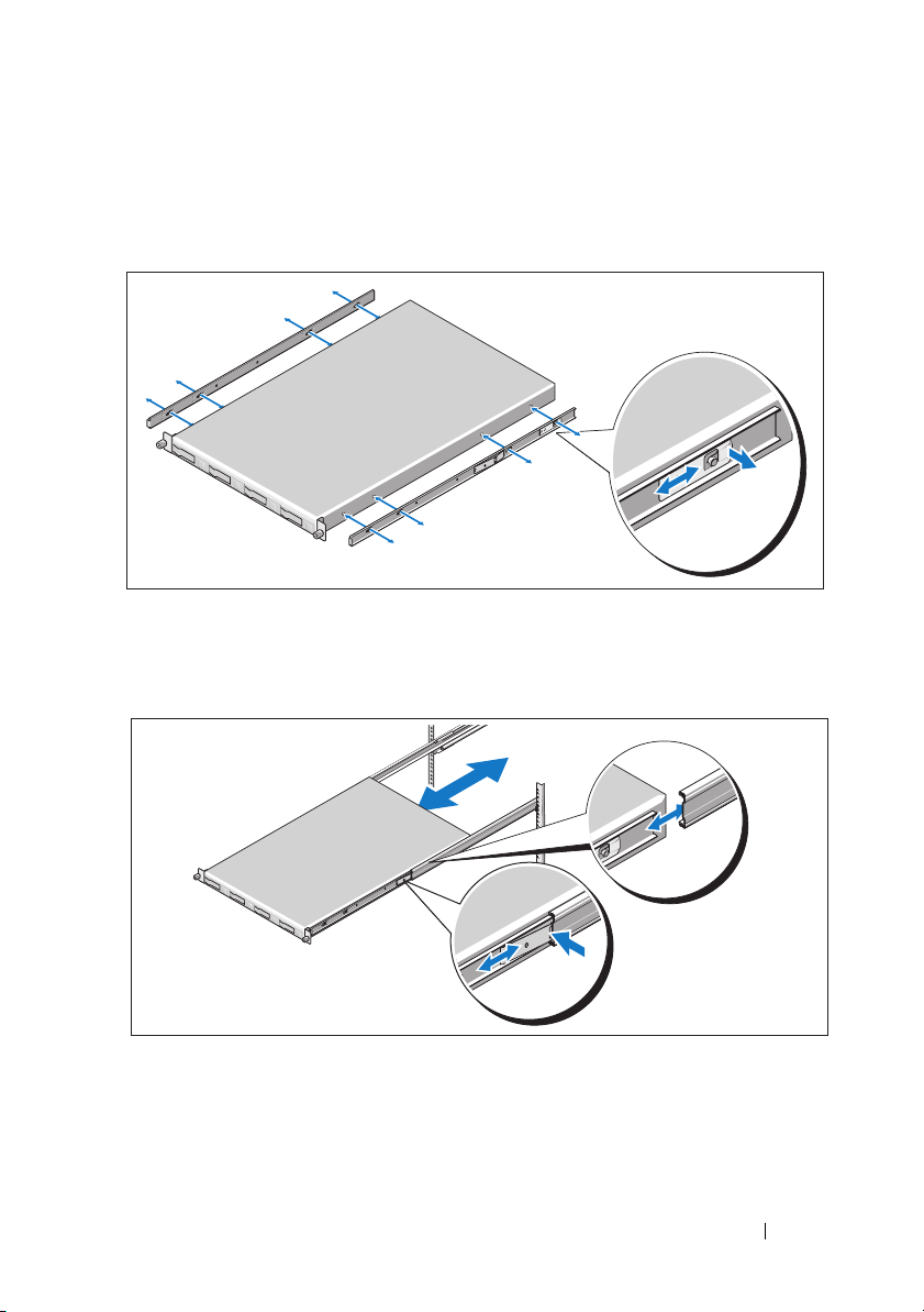
6
Push or pull the blue tab located near the front of the system and slide the
system into the rack. Tighten the thumbscrews to secure the ears of system
to the front of the rack.
Optional – Connecting the Keyboard, Mouse, and Monitor
Connect the keyboard, mouse, and monitor (optional).
The connectors on the back of your system have icons indicating which cable
to plug into each connector. Be sure to tighten the screws (if any) on the
monitor's cable connector.
8 Getting Started With Your System

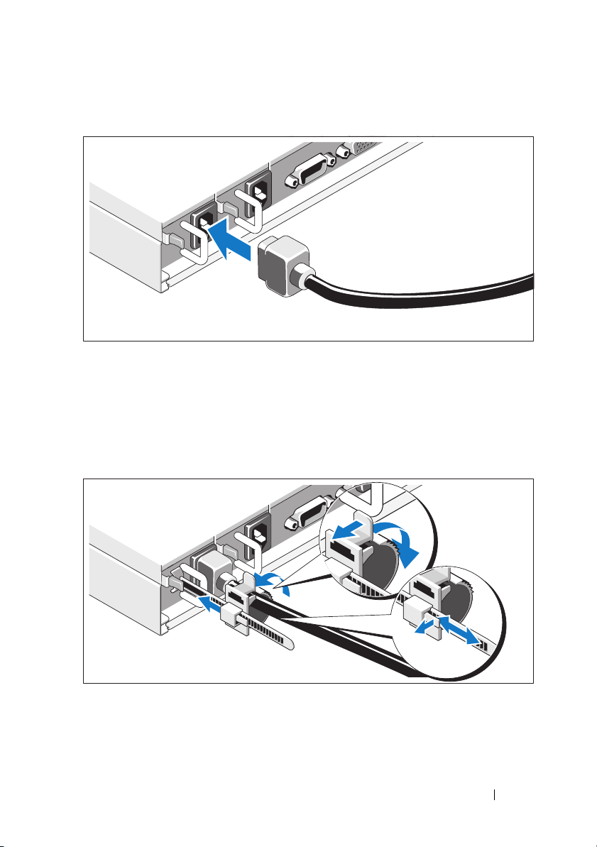
Connecting the Power Cable(s)
Connect the system’s power cable(s) to the system and, if a monitor is used,
connect the monitor’s power cable to the monitor. Plug the other end of the
power cables into a grounded electrical outlet or a separate power source such
as an uninterrupted power supply (UPS) or a power distribution unit (PDU).
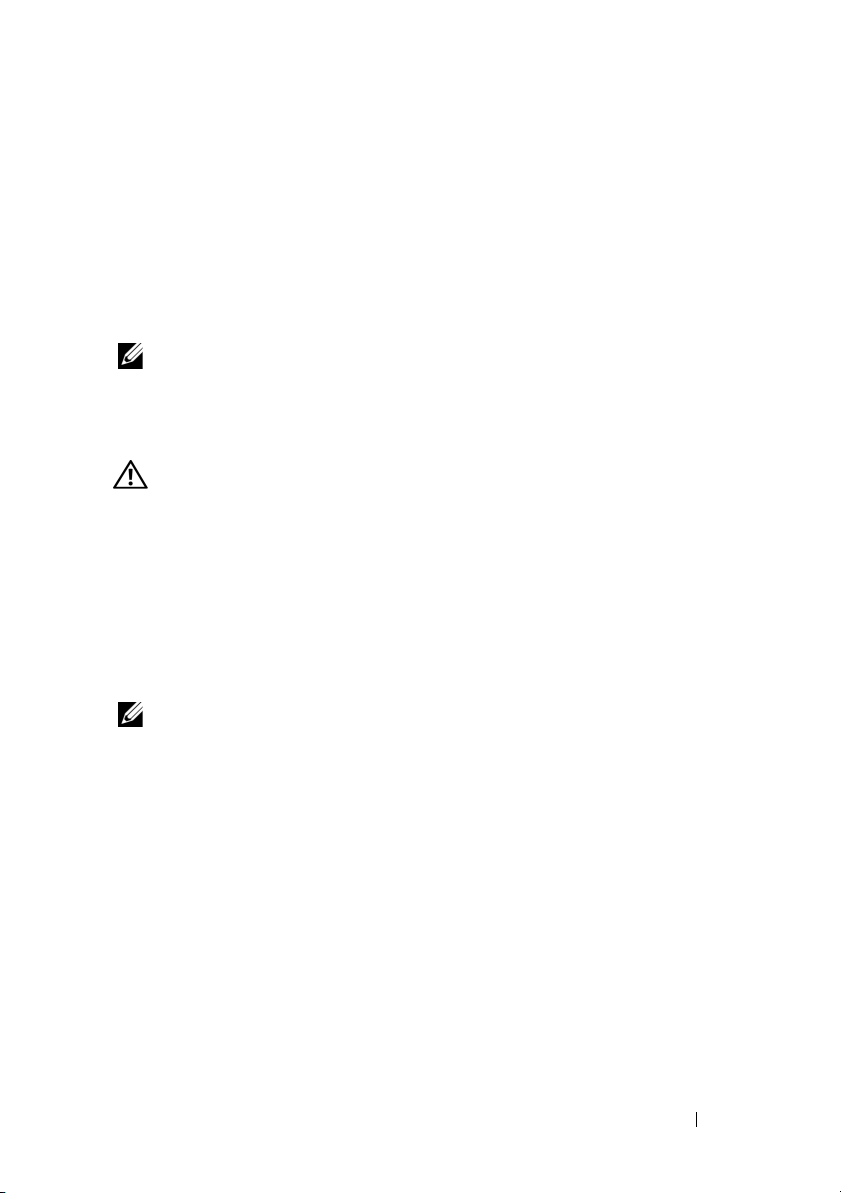
Securing the Power Cable(s)
Release the latch on the retainer unit and pull the clamping ring towards
the end of the strip. Open the clamping ring and insert the power cable.
Close and push back the clamping ring until it is as close as possible to
the system. Check to ensure that the power cable is secured to the system.
Getting Started With Your System 9
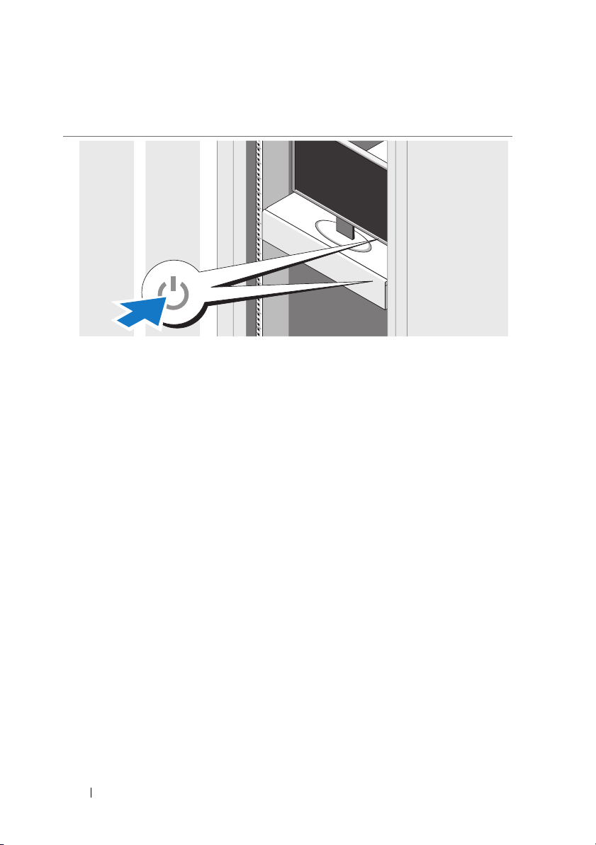
Turning On the System
Press the power button on the system and the monitor. The power indicators
should light.
Complete the Operating System Setup
To install an operating system, see the installation and configuration
documentation for your operating system. Be sure the operating system
is installed before installing hardware or software not purchased with
the system.
10 Getting Started With Your System

Supported Operating Systems
•Red Hat® Enterprise Linux® 5.4 Standard edition (x64)
• Red Hat Enterprise Linux 5.4 Standard edition (x86)
®
•SUSE
•Citrix
•VMware
NOTE: For the latest information on supported operating systems,
see support.dell.com.
Linux Enterprise Server 11 (x86_64)
®
XenServer™ Enterprise edition 5.x
®
ESX Server Version 4.0, Update 1
Other Information You May Need
WARNING: See the safety and regulatory information that shipped with your
system. Warranty information may be included within this document or as a
separate document.
The Hardware Owner’s Manual provides information about system features
and describes how to troubleshoot the system and install or replace system
components. This document is available online at support.dell.com/manuals.
The Dell systems management application documentation provides
information about installing and using the systems management software.
This document is available online at support.dell.com/manuals.
NOTE: Always check for updates on support.dell.com/manuals and read
the updates first because they often supersede information in other documents.
Getting Started With Your System 11

Technical Specifications
Processor
®
Processor type One or two Intel
processors (up to six core processors)
Expansion Bus
Bus type PCI Express Generation 2
Expansion slots
PCIe
Mezzanine/Daughter slots
PCIe
Memory
Architecture 1067 and 1333 MHz DDR-3 registered
Memory module sockets Eighteen 240-pin DIMMs
Memory module capacities 2 GB, 4 GB, or 8 GB
Minimum RAM 12 GB RAM
Maximum RAM 144 GB RAM
One x16 half-length, full height
Two x4 custom slots
memory modules with Error Correcting Code
(ECC)
Xeon® 5500 or 5600 series
Drive
Hard drives Up to four 3.5-inch, hot-swappable
SAS/SATA hard drives
or
Up to ten 2.5-inch, hot-swappable
SAS/SATA/SSD hard drives
12 Getting Started With Your System

Connectors
Back
NIC
KVM over IP port
Serial
USB
Video
Front
USB (for 3.5-inch chassis only)
Video
Video type AST2050 video controller; VGA connector
Video memory 8 MB
Power
AC power supply (redundant and non-redundant)
Wattage 650 W
Vo lt ag e
Heat dissipation
Maximum inrush current
Batteries
System battery
ROMB battery (optional)
Two RJ-45 (for integrated 10/100/1000 Mbps
Ethernet)
Dedicated Ethernet port for remote
management access
9-pin, DTE, 16550-compatible
Two 4-pin, USB 2.0-compliant
15-pin VGA
Two 4-pin, USB 2.0-compliant
115–230 VAC, 50/60 Hz, 8/4 A
2217.8 BTU/hr maximum
Under typical line conditions and over
the entire system ambient operating range,
the inrush current may reach 60 A per power
supply for 10 ms or less.
CR 2032 3.0-V lithium coin cell
3.7 V lithium ion battery pack
Getting Started With Your System 13

Physical
Height 70.6 cm (27.8 in)
Width 43 cm (16.9 in)
Depth 4.3 cm (1.6 in)
Weight (maximum configuration) 18.5 kg (40.7 lb)
Weight (empty) 6.8 kg (14.9 lb)
Environmental
For additional information about environmental measurements for specific system
configurations, see www.dell.com/environmental_datasheets.
Temperature
Operating
10° to 35°C (50° to 95°F) with a maximum
temperature gradation of 10°C per hour
NOTE: For altitudes above 2950 feet,
the maximum operating temperature
is derated 1ºF/550 ft.
Storage
Relative humidity
Operating
Storage
–40° to 65°C (–40° to 149°F) with a
maximum temperature gradation of
20°C per hour
8% to 85% (noncondensing) with a maximum
humidity gradation of 10% per hour
5% to 95% (noncondensing)
Maximum vibration
Operating
Storage
0.26 Grms at 5-350 Hz
1.54 Grms at 10-250 Hz for 15 mins
14 Getting Started With Your System

Environmental (continued)
Maximum shock
Operating
Storage
Altitude
Operating
Storage
Airborne Contaminant Level
Class
One shock pulse in the positive z axis
(one pulse on each side of the system)
of 31 G for 2.6 ms in the operational
orientation
Six consecutively executed shock pulses
in the positive and negative x, y, and z axes
(one pulse on each side of the system)
of 71 G for up to 2 ms
Six consecutively executed shock pulses
in the positive and negative x, y, and z axes
(one pulse on each side of the system) of
32 G fair squared wave pulse with velocity
at 270 inches/second (686 cms/sec).
–16 to 3,048 m (–50 to 10,000 ft)
NOTE: For altitudes above 2950 feet,
the maximum operating temperature is
derated 1ºF/550 ft.
–16 to 12,000 m (–50 to 35,000 ft)
G2 or lower as defined by ISA-S71.04-1985
Getting Started With Your System 15

16 Getting Started With Your System

Dell™ PowerEdge™ C1100
Začínáme
se systémem
Regulatorní model CS24-TY

Poznámky a upozornění
POZNÁMKA: POZNÁMKA označuje důležité informace, které pomáhají
lepšímu využití počítače.
UPOZORNĚNÍ: UPOZORNĚNÍ poukazuje na možnost poškození
hardwaru nebo ztráty dat v případě nedodržení pokynů.
VAROVÁNÍ: VAROVÁNÍ upozorňuje na potenciální nebezpečí
poškození majetku, úrazu nebo smrti.
____________________
Informace v tomto dokumentu se mohou bez předchozího upozornění změnit.
© 2010 Dell Inc. Všechna práva vyhrazena.
Jakákoli reprodukce těchto materiálů bez písemného povolení společnosti Dell Inc. je přísně zakázána.
Ochranné známky použité v tomto textu: Dell, logo DELL a PowerEdge jsou ochranné známky
společnosti Dell Inc. Citrix a XenServer jsou ochranné známky společnosti Citrix Systems, Inc. a/
nebo jejích poboček a mohou být registrovány úřadem pro patenty a ochranné známky v USA a dalších
zemích. Intel a Xeon jsou registrované ochranné známky společnosti Intel Corporation v USA a dalších
zemích. VMware je registrovaná ochranná známka společnos ti VMware, Inc. v USA a dalších zemích.
Red Hat a Red Hat Enterprise Linux jsou registrované ochranné známky společnosti Red Hat, Inc. v
USA a dalších zemích. SUSE je registrovaná ochranná známka společnosti Novell, Inc. v USA a
dalších zemích.
V tomto dokumentu mohou být použity další ochranné známky a obchodní názvy s odkazem na
společnosti vlastnící tyto známky a názvy nebo na jejich produkty. Společnost Dell Inc. nemá
vlastnické zájmy vůči ochranným známkám a obchodním názvům jiným než svým vlastním.
Regulatorní model CS24-TY
Únor 2010 Č. dílu 6WK8G Rev. A00
Instalace a konfigurace
VAROVÁNÍ: Před provedením následujícího postupu si prostudujte
bezpečnostní pokyny dodané se systémem.
Rozbalení systému
Rozbalte systém a identifikujte jeho jednotlivé součásti.
Instalace stojanového řešení s přístupem pomocí nářadí
VAROVÁNÍ: Při každém zvedání systému požádejte o asistenci.
Systém nezvedejte sami, vyvarujete se tak možného zranění.
VAROVÁNÍ: Systém není připevněn ke stojanu ani ke kolejničkám.
Chcete-li předejít možnosti zranění osob nebo poškození systému,
je třeba systémový stojan během instalace a vyjímání dostatečně
stabilizovat.
UPOZORNĚNÍ:
a boční stabilizátory (na samostatně stojících stojanech) nebo přední
stabilizátory (na vzájemně spojených stojanech). Pokud nenainstalujete
před instalací systémů do stojanu stabilizátory, může dojít k převrhnutí
stojanu, což může za určitých okolností vést k úrazu. Proto před
instalací komponent do stojanu vždy instalujte stabilizátory.
UPOZORNĚNÍ:
servisní technik. Sami byste měli pouze řešit menší potíže a provádět
jednoduché opravy, ke kterým vás opravňuje dokumentace k produktu
nebo ke kterým vás vyzve tým služeb a podpory online či po telefonu.
Na škody způsobené neoprávněným servisním zásahem se nevztahuje
záruka. Přečtěte si a dodržujte bezpečnostní pokyny dodané
s produktem.
Před instalací systémů do stojanu nainstalujte přední
Mnohé z oprav smí provádět pouze certifikovaný
Začínáme se systémem 19
1
Nainstalujte výsuvné kolejničky do stojanu.
2
Zarovnejte vnitřní kolejničky s výsuvnými kolejničkami stojanu a zatlačte
systém do výsuvných kolejniček, dokud zamykací západka nezaklapne na
své místo.
20 Začínáme se systémem
3
Zasuňte systém do stojanu a pomocí šroubků upevněte ouška na systému k
přední části stojanu.
Instalace stojanového řešení s přístupem bez nářadí
VAROVÁNÍ: Při každém zvedání systému požádejte o asistenci.
Systém nezvedejte sami, vyvarujete se tak možného zranění.
VAROVÁNÍ: Systém není připevněn ke stojanu ani ke kolejničkám.
Chcete-li předejít možnosti zranění osob nebo poškození systému,
je třeba systémový stojan během instalace a vyjímání dostatečně
stabilizovat.
UPOZORNĚNÍ:
a boční stabilizátory (na samostatně stojících stojanech) nebo přední
stabilizátory (na vzájemně spojených stojanech). Pokud nenainstalujete
před instalací systémů do stojanu stabilizátory, může dojít k převrhnutí
stojanu, což může za určitých okolností vést k úrazu. Proto před
instalací komponent do stojanu vždy instalujte stabilizátory.
UPOZORNĚNÍ:
otvory je důležité zajistit, aby byl do čtvercových otvorů zasunut
čtyřhranný kolík.
Před instalací systémů do stojanu nainstalujte přední
Při instalaci kolejniček do stojanu se čtvercovými
Začínáme se systémem 21
1
Zarovnejte koncovky kolejniček se svislými přírubami stojanu a usaďte
kolíky do dolního otvoru prvního tvaru U a do horního otvoru druhého
tvaru U. Usaďte zadní konec kolejničky tak, aby západka zaklapla na místo.
POZNÁMKA: Kolejničky lze použít ve stojanech se čtvercovými i
kulatými otvory.
2
Zopakováním předchozích kroků usaďte a připevněte ke svislé přírubě
přední konec kolejničky.
3
Chcete-li kolejničky vyjmout, můžete je uvolnit zatažením za uvolňovací
knoflík ve středu zadního konce kolejničky.
22 Začínáme se systémem

4
Vyrovnejte čtyři sloty ve tvaru klíčové dírky na kolejničkách pro šasi s
odpovídajícími kolíky na systému a posuňte kolejničky pro šasi směrem k
zadní části systému, dokud nezaklapnou na místo.
5
Zarovnejte konce kolejniček pro šasi s konci kolejniček ve stojanu a zasuňte
systém dovnitř, dokud kolejničky pro šasi nezaklapnou na místo.
Začínáme se systémem 23

6
Zatáhněte za modrý výstupek blízko přední části systému nebo na něj
zatlačte a zasuňte systém do stojanu. Pomocí šroubků upevněte ouška na
systému k přední části stojanu.
Volitelné – Připojení klávesnice, myši a monitoru
Připojte klávesnici, myš a monitor (volitelné).
Konektory na zadní straně systému mají ikony znázorňující, který kabel se má
připojit ke kterému konektoru. Zajistěte, aby šrouby na konektoru kabelu monitoru
byly dobře dotaženy (je-li jimi konektor vybaven).
24 Začínáme se systémem
Připojení napájecích kabelů
Připojte napájecí kabely k systému, a pokud používáte monitor, připojte napájecí
kabel také k monitoru. Poté zasuňte druhý konec napájecích kabelů do uzemněné
elektrické zásuvky nebo je připojte k samostatnému zdroji napájení, například ke
zdroji nepřerušitelného napájení (UPS) nebo jednotce rozvaděče (PDU).
Zajištění napájecích kabelů
Uvolněte západku na zajišt’ovací jednotce a zatáhněte upínací kroužek směrem ke
konci pásku. Otevřete upínací kroužek a vložte do něj napájecí kabel. Zavřete
upínací kroužek a zatlačte jej zpět co nejblíže k systému. Zkontrolujte, zda je
napájecí kabel připevněn k systému.
Začínáme se systémem 25

Zapnutí systému
Stiskněte vypínač na systému a na monitoru. Indikátory napájení by se měly
rozsvítit.
Dokončení nastavení operačního systému
Chcete-li provést instalaci operačního systému, postupujte podle dokumentace
k instalaci a konfiguraci operačního systému. Než začnete s instalací hardwaru
či softwaru, který nebyl zakoupen společně se systémem, ujistěte se,
že je nainstalován operační systém.
26 Začínáme se systémem
Podporované operační systémy
•
Red Hat® Enterprise Linux® 5.4, edice Standard (x64)
•
Red Hat Enterprise Linux 5.4, edice Standard (x86)
•
SUSE® Linux Enterprise Server 11 (x86_64)
•
Citrix® XenServer™ Enterprise 5.x
•
VMware® ESX Server verze 4.0, aktualizace 1
POZNÁMKA: Nejnovější informace o podporovaných operačních
systémech naleznete na webu support.dell.com.
Další užitečné informace
VAROVÁNÍ: Prostudujte si informace o bezpečnosti a předpisech,
které byly dodány se systémem. Informace o záruce jsou součástí
tohoto dokumentu nebo jsou přiloženy samostatně.
Příručka majitele hardwaru
řešení problémů se systémem a instalaci nebo výměnu komponent. Tento
dokument je k dispozici online na adrese
Dokumentace k aplikaci pro správu systémů Dell poskytuje informace o instalaci
a použití softwaru pro správu systémů. Tento dokument je k dispozici online na
adrese
support.dell.com/manuals
POZNÁMKA: Vždy nejprve zkontrolujte a pročtěte aktualizace uvedené na
adrese support.dell.com/manuals, protože tyto aktualizace často
nahrazují informace v ostatních dokumentech.
obsahuje informace o funkcích systému a popisuje
support.dell.com/manuals
.
.
Začínáme se systémem 27

Technické specifikace
Procesor
Typ procesoru Jeden nebo dva procesory řady Intel® Xeon®
5500 nebo 5600 (procesory s až šesti jádry)
Rozšiřovací sběrnice
Typ sběrnice PCI Express 2. generace
Rozšiřovací sloty
PCIe Jeden x16 s poloviční délkou a plnou výškou
Sloty na rozšiřovacích/dceřiných kartách
PCIe Dva vlastní sloty x4
Pamět’
Architektura Registrované pamět’ové moduly DDR3 s
taktovací frekvencí 1067 a 1333 MHz a s
ochranou ECC
Sloty pro pamět’ové moduly Osmnáct 240kolíkových slotů DIMM
Kapacity pamět’ových modulů 2 GB, 4 GB nebo 8 GB
Minimum paměti RAM 12 GB
Maximum paměti RAM 144 GB
Jednotky
Pevné disky Až čtyři 3,5palcové pevné disky SAS nebo
SATA vyměnitelné za provozu
nebo
Až deset 2,5palcových pevných disků SAS,
SATA nebo SSD vyměnitelných za provozu
28 Začínáme se systémem
 Loading...