

Dell PowerEdge B02S, PowerEdge C410x Hardware Owner's Manual

Dell PowerEdge C410x
Hardware Owner’s Manual
Notes, Cautions, and Warnings
NOTE:
A NOTE indicates important information that helps you make better use of your computer.
CAUTION:
A CAUTION indicates potential damage to hardware or loss of data if instructions are not
followed.
WARNING:
A WARNING indicates a potential for property damage, personal injury, or death.
Information in this publication is subject to change without notice.
© 2010-2011 Dell Inc. All rights reserved.
Reproduction of these materials in any manner whatsoever without the written permission of Dell Inc. is strictly
forbidden.
Trademarks used in this text: Dell™, the DELL logo, and PowerEdge™ are trademarks of Dell Inc.
Other trademarks and trade names may be used in this publication to refer to either the entities claiming the marks
and names or their products. Dell Inc. disclaims any proprietary interest in trademarks and trade names other than its
own.
Regulatory Model B02S
2011-08 Rev. A01

Contents | 3
Contents
1 INTRODUCTION ............................................ ...................................................... ....................................... 6
P
OWER SEQUENCE
.......................................................................................................................................................... 6
S
UPPORTED
GPGPU C
ONFIGURATIONS
.............................................................................................................................. 6
GPGPU S
UPPORT LIMITATION
.......................................................................................................................................... 6
I
NFINIBAND
(IB) S
UPPORT LIMITATION
............................................................................................................................... 7
C
HECKLIST
..................................................................................................................................................................... 7
2 PRODUCT OVERVIEW ......................................... ........................................................................................ 8
A T
OUR OF THE SYSTEM
................................................................................................................................................... 8
System Front View ................................................................................................................................................. 8
System Back View .................................................................................................................................................. 9
S
YSTEM
LEDS D
ESCRIPTION
............................................................................................................................................ 10
Front System LEDs................................................................................................................................................ 10
Static / Dynamic IP Switch Function Instruction .................................................................................................. 11
3 REMOVING AND INSTALLING HARDWARE. ............................................ .................................................... 12
S
AFETY MEASURES
........................................................................................................................................................ 12
S
YSTEM COVER
............................................................................................................................................................ 13
Removing System Cover ....................................................................................................................................... 13
Installing the system cover .................................................................................................................................. 15
PCI C
AGE
.................................................................................................................................................................... 16
Removing the PCI Cage ........................................................................................................................................ 16
Installing the PCI cage.......................................................................................................................................... 17
PCIE C
ARD
.................................................................................................................................................................. 17
Replacing PCIe Card ............................................................................................................................................. 17
For M1060 Card ................................................................................................................................................... 17
Installing the M1060 card .................................................................................................................................... 18
For M2050/M2070/M2070Q/M2075/M2090 Cards ........................................................................................... 19
Installing the M2050/M2070/M2070Q/M2075/M2090 card ............................................................................. 21
S
YSTEM FANS
............................................................................................................................................................... 22
Replacing System Fans ......................................................................................................................................... 22
Installing the system fans .................................................................................................................................... 24
F
AN CAGE
.................................................................................................................................................................... 25
Replacing System Fan Cage ................................................................................................................................. 25

Contents | 4
Installing the system fan cage ............................................................................................................................. 29
P
OWER SUPPLY
............................................................................................................................................................ 30
Replacing Power Supplies .................................................................................................................................... 30
P
OWER DISTRIBUTION BOARD
(PDB) ............................................................................................................................... 33
Replacing Power Distribution Board (PDB) .......................................................................................................... 33
Installing the power distribution board ............................................................................................................... 39
IPASS BOARD
............................................................................................................................................................... 40
Replacing iPass Board .......................................................................................................................................... 40
Installing the iPass board ..................................................................................................................................... 48
M
IDDLE BOARD
............................................................................................................................................................ 49
Replacing Middle Board ....................................................................................................................................... 49
Installing the system middle board ...................................................................................................................... 50
F
RONT
I/O P
ANEL
........................................................................................................................................................ 51
Removing Front I/O Panel .................................................................................................................................... 51
Installing the Front IO panel ................................................................................................................................ 52
I
NSTALLING THE RAIL AND THE SYSTEM
............................................................................................................................. 53
4 CABLE ROUTINGS ............................................................ ......................................................................... 56
IPASS PORT MAPPING
................................................................................................................................................... 57
5 BMC REMOTE MANAGEMENT CONSOLE ........................................................................... ........... ............. 58
I
NITIAL CONFIGURATION USING A
DHCP S
ERVER
................................................................................................................ 58
S
TATIC
/DHCP IP C
ONTROLLED BY FRONT PANEL BUTTON
................................................................................................... 59
R
EMOTE MANAGEMENT CONSOLE OVERVIEW
................................................................................................................... 60
E
NTER DELL REMOTE MANAGEMENT CONSOLE
.................................................................................................................. 61
Properties ............................................................................................................................................................. 61
C
ONFIGURATION
.......................................................................................................................................................... 62
Network ............................................................................................................................................................... 62
Security ................................................................................................................................................................ 63
Users .................................................................................................................................................................... 64
Services ................................................................................................................................................................ 65
IPMI .......................................................................................................................................................................... 66
S
ESSIONS
.................................................................................................................................................................... 68
U
PDATES
..................................................................................................................................................................... 69
Utilities ................................................................................................................................................................. 70
S
ERVER INFORMATION
................................................................................................................................................... 71

Contents | 5
Power Control ...................................................................................................................................................... 71
Power Consumption ............................................................................................................................................. 72
GPU Power Consumption ..................................................................................................................................... 73
Thermal ................................................................................................................................................................ 74
Fans ...................................................................................................................................................................... 74
Temperatures....................................................................................................................................................... 74
S
YSTEM EVENT LOG
...................................................................................................................................................... 75
Platform Events.................................................................................................................................................... 76
Traps Settings ...................................................................................................................................................... 77
Email Settings ...................................................................................................................................................... 78
Port Map .............................................................................................................................................................. 79
6 TROUBLESHOOTING YOUR SYSTEM ............................ ............................................ .................................. 80
S
AFETY FIRST—FOR YOU AND YOUR SYSTEM
........................................................................................................................... 80
Checking GPU Card .............................................................................................................................................. 81
Checking iPass Cable ............................................................................................................................................ 81
Checking iPass Connector to Host System ........................................................................................................... 82
Check if iPass Board (GS-IPASS2 / GS-IPASS3) is installed properly ..................................................................... 82
7 JUMPERS AND CONNECTORS . .................................................................................................. ................ 83
D
ELL POWEREDGE
C410X M
IDDLE BOARD CONNECTORS AND JUMPERS
.......................................................................................... 83
8 GETTING HELP ................................................... ...................................................................................... 84
C
ONTACTING DELL
.......................................................................................................................................................... 84
9 INDEX ........................................... ............................................ ........... ............................................ ........ 85

Introduction | 6
1
Introduction
Power Sequence
It is recommended that the following power sequence be followed when using the C410x with a host
server.
1. For a single host server connected to a C410x:
a. Power up the C410x.
b. Wait for the Green power LEDs on the individual PCI cages to light.
c. Power up the host server.
2. For multiple host servers connected to a C410x:
a. Power up the PCI cage associated with the iPass port connected to the C410x.
NOTE: The PCI cage power can be applied by pressing the cage power button or using
IPMITool commands identified in the “Using the C410x Base Board Management Controller”
document.
b. Wait for the Green power LEDs on the cage to light.
c. Power up the host server.
d. Repeat for each host server connected to the C410x.
Supported GPGPU Configurations
The C410x supports installing different GPGPU and other devices in the chassis.
Mixing different GPGPUs connected to the same host server is not supported. All GPGPUs connected to a
host server must be the same type.
Mixing other devices with GPGPUs connected to the same host server is supported.
GPGPU Support Limitation
There are some host servers that have multiple PCIex16 expansion slots. This allows multiple Host
Interface Cards (HIC) to be installed in a single host server. The flexibility of the C410x system allows 16
GPGPUs to be connected to a single host server with multiple PCIex16 expansion slots. Host servers that
are based on x86 architecture have a 16 bit (total 64 K) IO address space hardware limit. The 16 bit IO
address space hardware limit limits the number of PCI devices that can be connected to the host server.
The host server does not boot or other POST errors occur if the IO address space limit is exceeded. The
number of onboard host server PCI devices utilize a fixed amount of IO address space. The remaining IO
address space is used to determine the number of GPGPU that can be installed in a C410x that is
connected to the single host server. Each GPGPU requires 4K of IO address space. The number of
onboard PCI devices plus the number of GPGPUs determine the amount of IO address space used.
Therefore, the 16 bit IO address space limitation does not allow a single host server to support 16
GPGPUs installed in a C410x.

Introduction | 7
InfiniBand (IB) Support Limitation
Host servers will not support more than one IB card installed in a C410x.
If more than one IB card is installed in a C410x and connected to a single host server issues may be
observed.
Checklist
Carefully unpack the Dell PowerEdge C410X server and check that the following items were included.
• One Dell PowerEdge C410X system
• Dell PowerEdge C410x Getting Started Guide
• Safety, Environmental, and Regulatory Information (SERI)
• Warranty and Support Information (WSI) or End User License Agreement (EULA)
Product Overview | 8
2
Product Overview
A Tour of the System
The following sections describe the external features of the Dell PowerEdge C410X server.
System Front View
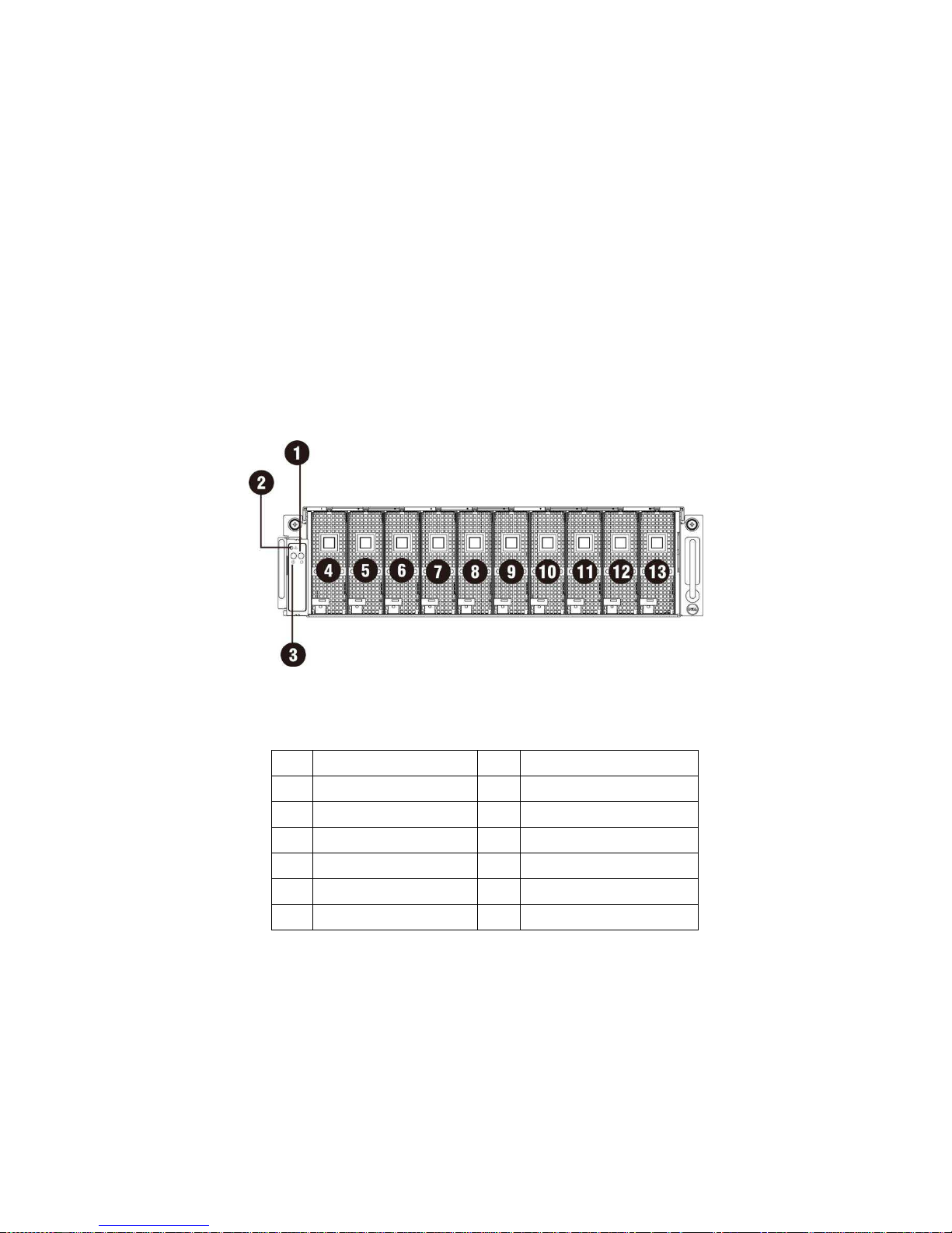
Figure 1 – Front View
1 Power LED/Button 8 PCI Cage 5
2 System LED 9 PCI Cage 6
3 UID LED/Button 10 PCI Cage 7
4 PCI Cage 1 11 PCI Cage 8
5 PCI Cage 2 12 PCI Cage 9
6 PCI Cage 3 13 PCI Cage 10
7 PCI Cage 4
Product Overview | 9
System Back View
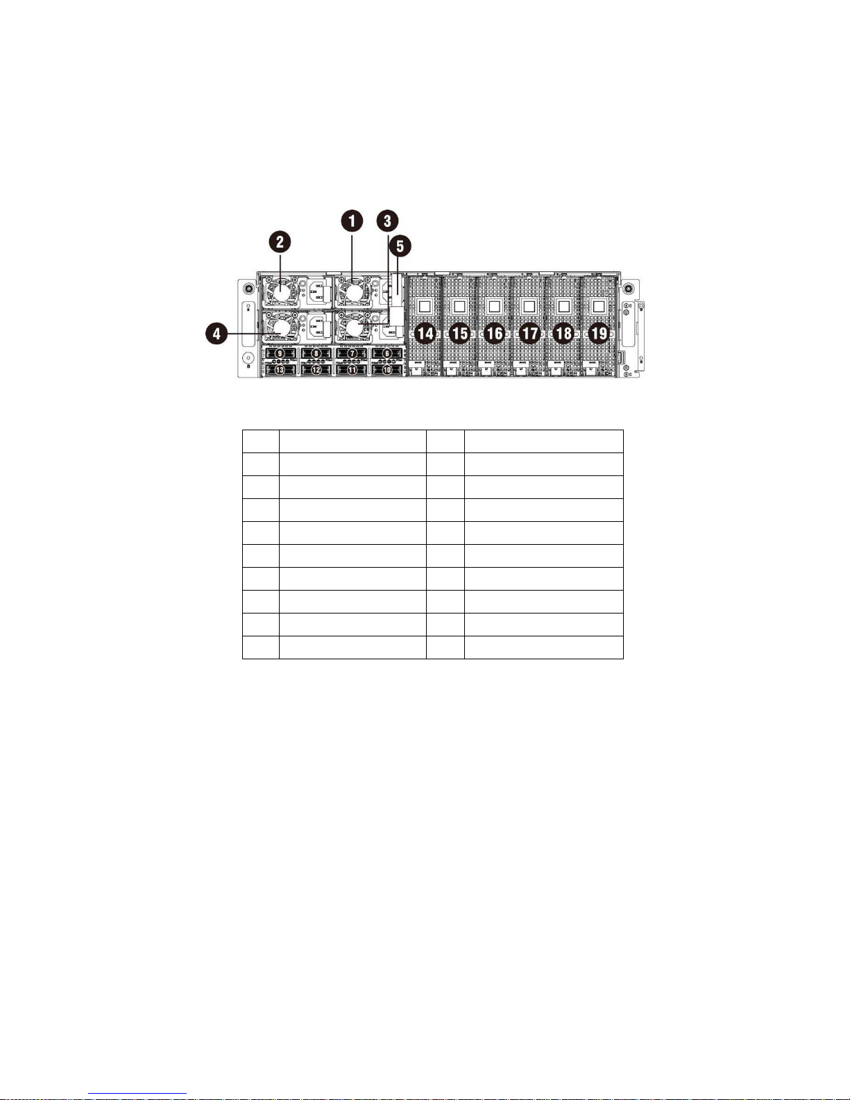
Back view of system is shown below:
Figure 2 – Back View
1 Power Module 1 11 iPass connector 6
2 Power Module 2 12 iPass connector 7
3 Power Module 3 13 iPass connector 8
4 Power Module 4 14 PCI Cage 11
5 BMC LAN Cable 15 PCI Cage 12
6 iPass connector 1 16 PCI Cage 13
7 iPass connector 2 17 PCI Cage 14
8 iPass connector 3 18 PCI Cage 15
9 iPass connector 4 19 PCI Cage 16
10
iPass connector 5
Product Overview | 10
System LEDs Description
Front System LEDs
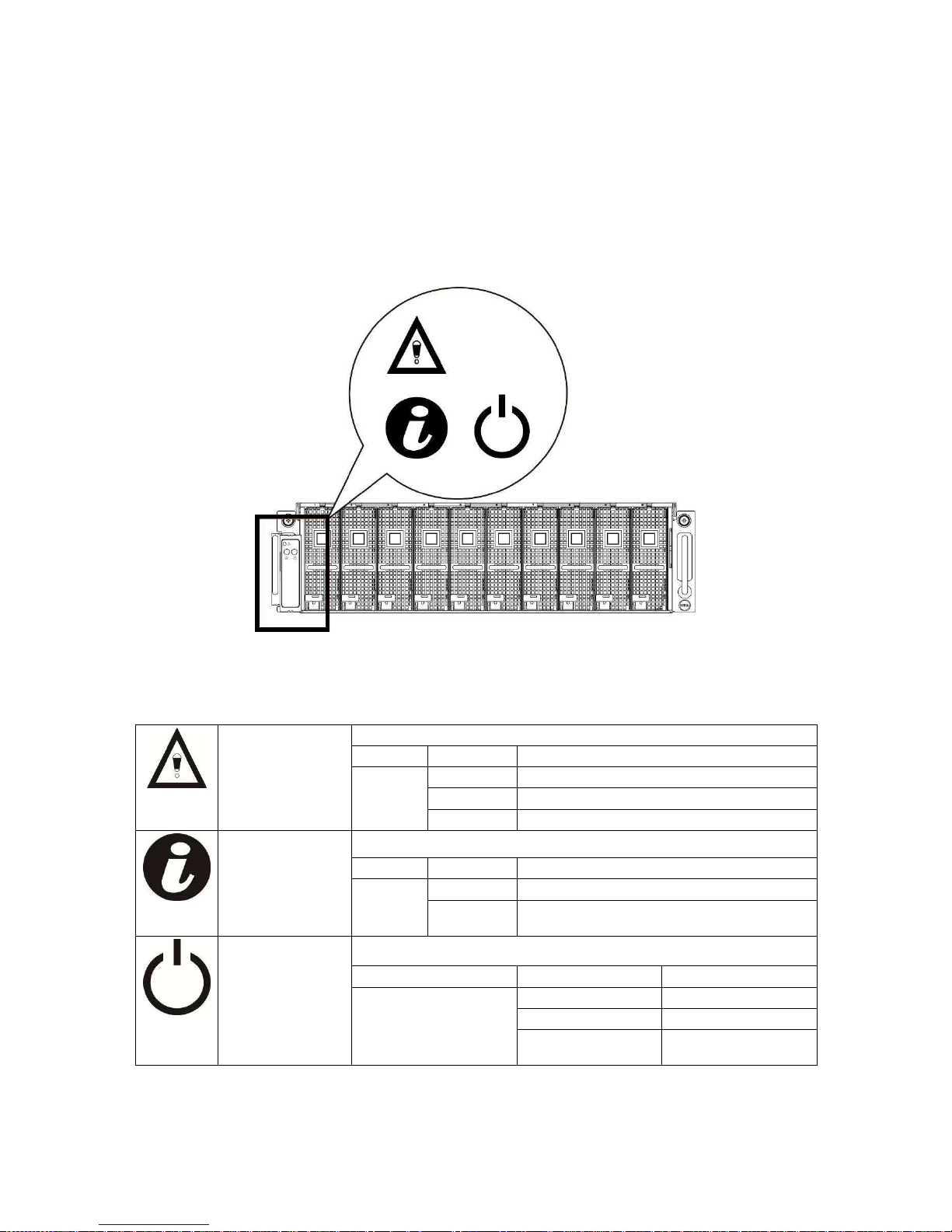
The front system LEDs contain System LED, Power LED and UID LED information.
The detailed LEDs information is listed below:
Figure 3 – Front System LEDs
Table 1-1. Front System LEDs
System LED Displays status/errors and is controlled by BMC.
Color Condition Occurrence
Amber Blink Fast Power supply fail
On FAN fail or sensor error
Blink GPU card fail
UID LED Lights when front or rear ID button is pressed.
Color Condition Occurrence
Blue Off No identification
Blinking ID Button pressed on system (ID command
executed)
Power LED
Lights green when server is powered on.
Color Condition Occurrence
Green
On Power on
Off Power off
Blinking
Power on fail or without
any GPU card

Product Overview | 11
Static / Dynamic IP Switch Function Instruction
To switch from DHCP to static or vice versa:
Hold down the ID button for 5 seconds
While pressing the ID button, press and hold the power button for 5 seconds
Release the power button, and then the ID button
It will take ~30 seconds to change the configuration
The ID light will indicate which mode has been selected:
- Solid for 5 seconds indicates static IP
- Flashing for 5 seconds indicates DHCP
If the default IP address is changed, switching DHCP to static IP will change the IP address back to the
default.
Default IP address is 192.168.0.120

Removing and Installing Hardware | 12
3
Removing and Installing Hardware
Safety Measures
CAUTION: Many repairs may only be done by a certified service technician. You should only perform
troubleshooting and simple repairs as authorized in your product documentation, or as directed by the
online or telephone service and support team. Damage due to servicing that is not authorized by Dell is not
covered by your warranty. Read and follow the safety instructions that came with the product.
CAUTION: Computer components and electronic circuit boards can be damaged by discharges of
static electricity. Working on computers that are still connected to a power supply can be extremely
dangerous. Follow the simple guidelines below to avoid damage to your computer or injury to yourself.
• Always disconnect the computer from the power outlet whenever you are working inside the
computer case.
• If possible, wear a grounded wrist strap when you are working inside the computer case.
Alternatively, discharge any static electricity by touching the bare metal system of the
computer case, or the bare metal body of any other grounded appliance.
• Hold electronic circuit boards by the edges only. Do not touch the components on the board
unless it is necessary to do so. Do not flex or stress the circuit board.
• Leave all components inside the static-proof packaging until you are ready to use the
component for the installation.
Removing and Installing Hardware | 13
System Cover
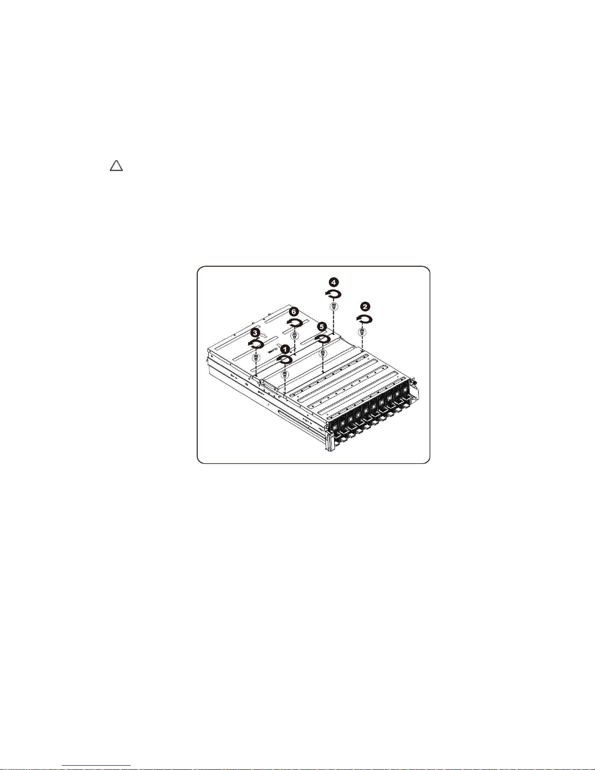
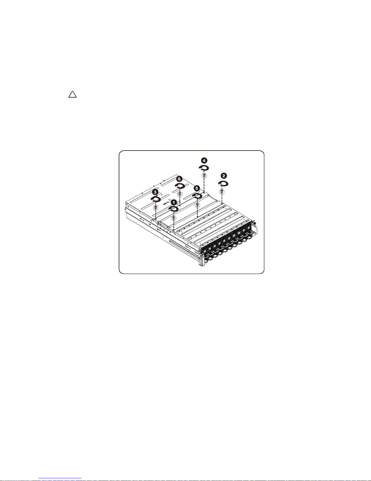
Removing System Cover
CAUTION:
Before you remove or install the system cover: Make sure the system is not
turned on or connected to AC power.
Follow these instructions to remove the system cover:
1. Loosen and remove the screws securing the middle cover.
Removing and Installing Hardware | 14
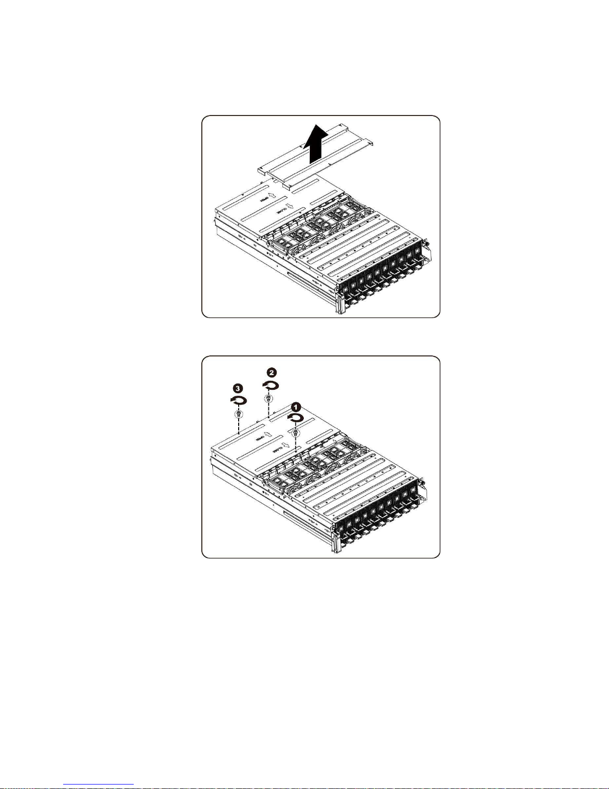
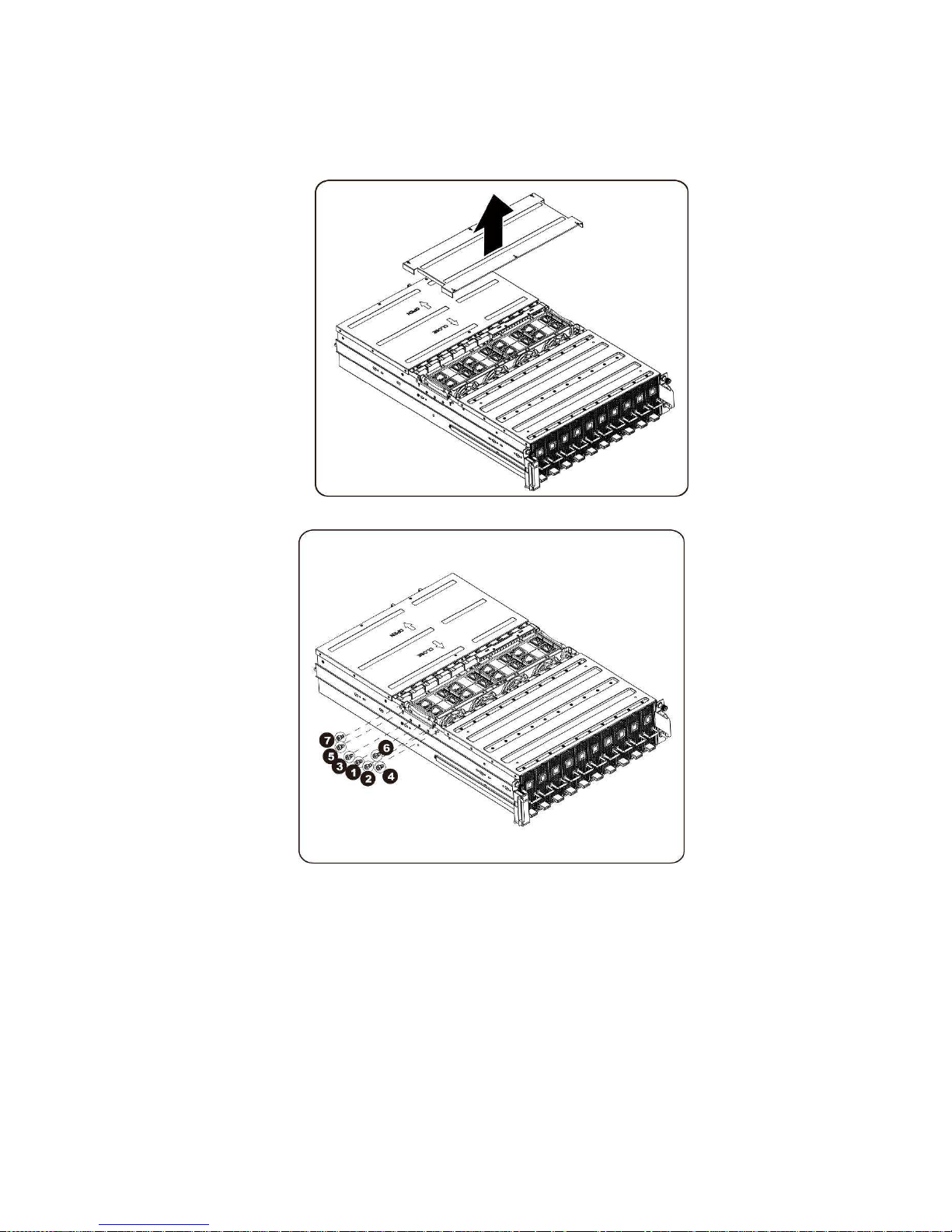
2. Remove the middle top cover from the system.
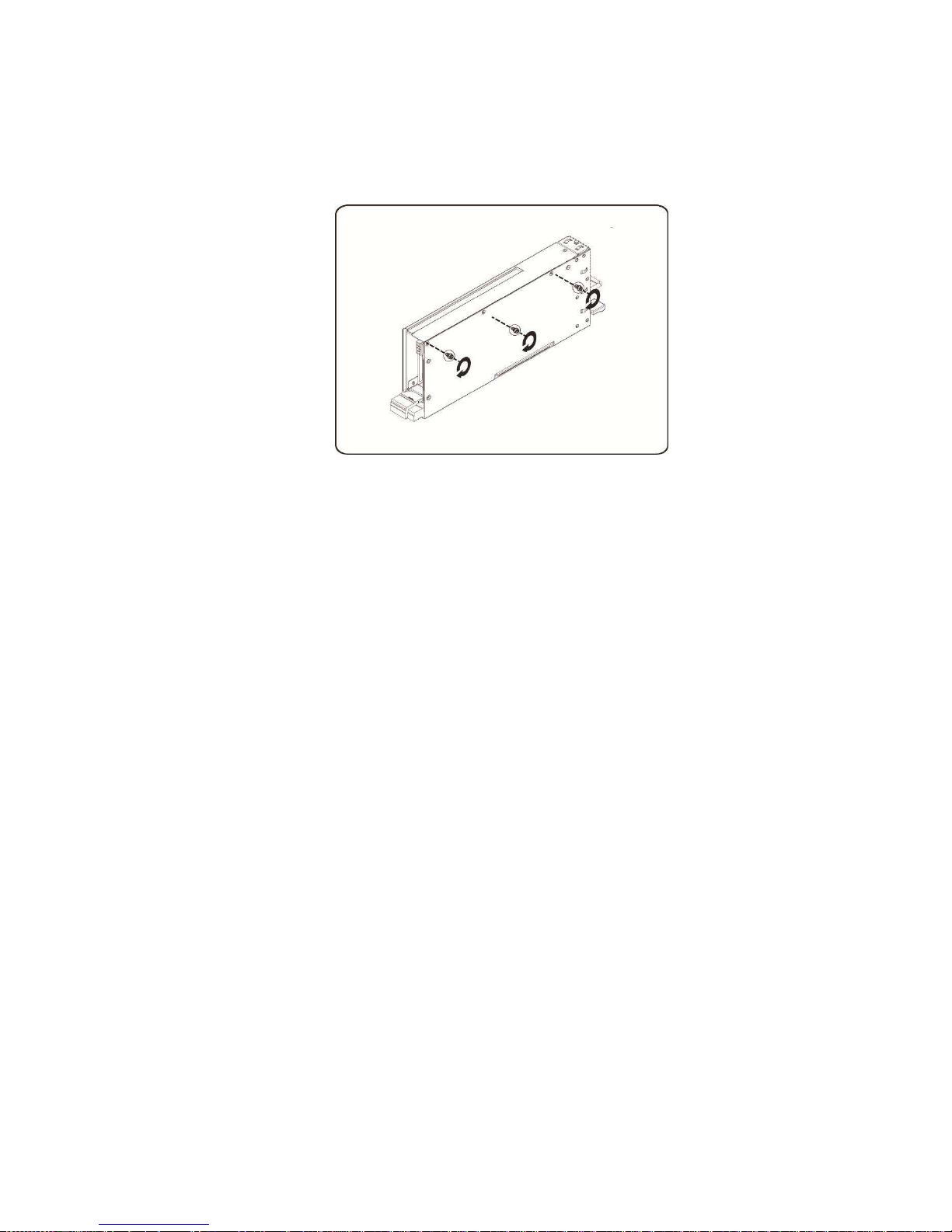
3. Loosen and remove the screws securing the back cover.
Removing and Installing Hardware | 15
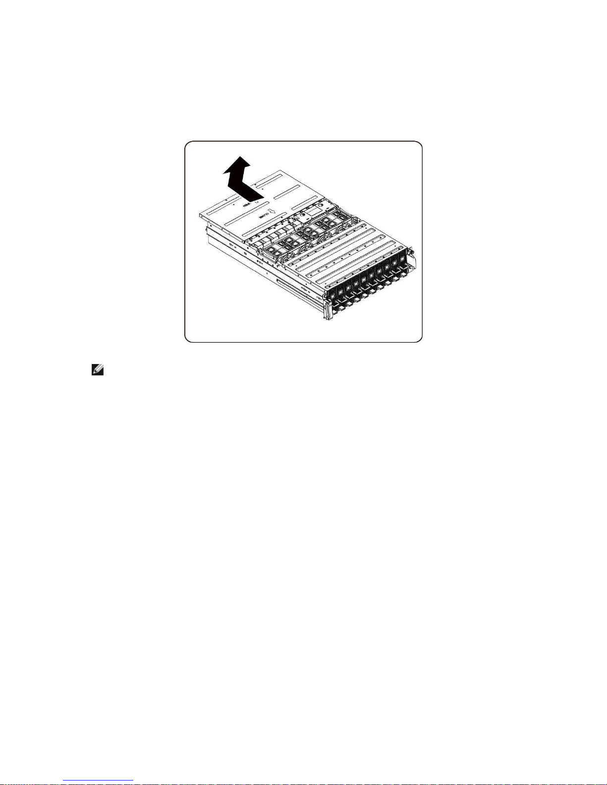
4. Slide the cover horizontally to the back using the traction pad and remove the back cover in
the direction of the arrow.
NOTE:
This system must be operated with the system cover installed to ensure proper cooling.
Installing the system cover
To install the system cover follow the instructions for removing the system cover in the reverse order.
Removing and Installing Hardware | 16
PCI Cage
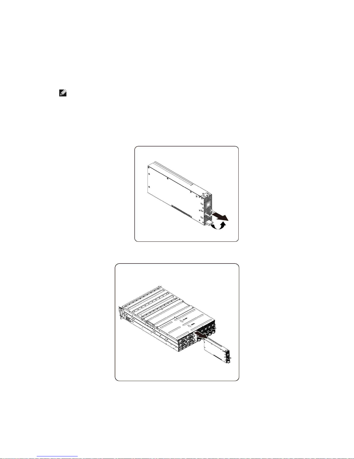
Removing the PCI Cage
NOTE:
• Take note of the drive tray orientation before sliding it out.
• The tray will not fit back into the bay if inserted incorrectly.
1. Lift the release lever and pull on the cage handle at the same time.
2. Slide the cage assembly out of the system.
Removing and Installing Hardware | 17
Installing the PCI cage
To install the PCI cage follow the instructions for removing the PCI cage in the reverse order.
PCIe Card
Replacing PCIe Card
CAUTION:
Before you remove or install the PCIe card, press PCI cage power button to
turn off the specific single PCI cage power before replacing PCIe card.
Follow these instructions to replace a PCIE card:
For M1060 Card
1. See to Chapter 4 Cable Routings on page 57 to connect switch button cable and PCI power cable.
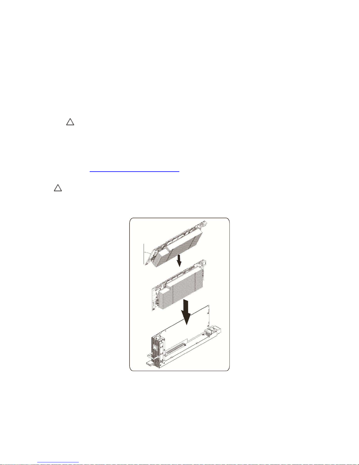
2. Insert the PCIe card by 45 degree and push it into the socket vertically.
CAUTION: Care should be taken to prevent damage to components on the back side of the PCIe card.
Make sure the card does not drag across the card mounting standoffs of the cage when inserting the card
into the socket.
Removing and Installing Hardware | 18
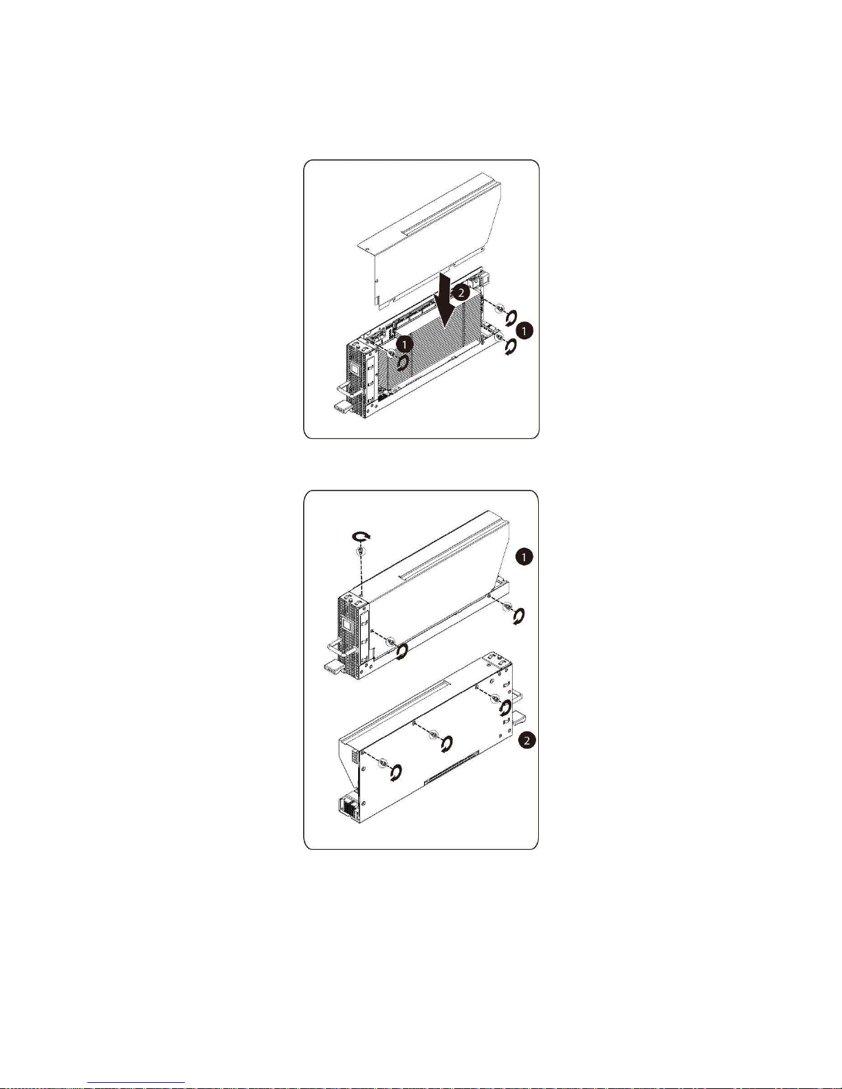
3. Secure the card in place with screws and place the PCI side cover as shown in the illustration.
4. Secure the PCI side cover and back cover in place with screws.
Installing the M1060 card
To install the M1060 card follow the instructions for removing the M1060 card in the reverse order.
Removing and Installing Hardware | 19
For M2050/M2070/M2070Q/M2075/M2090 Cards
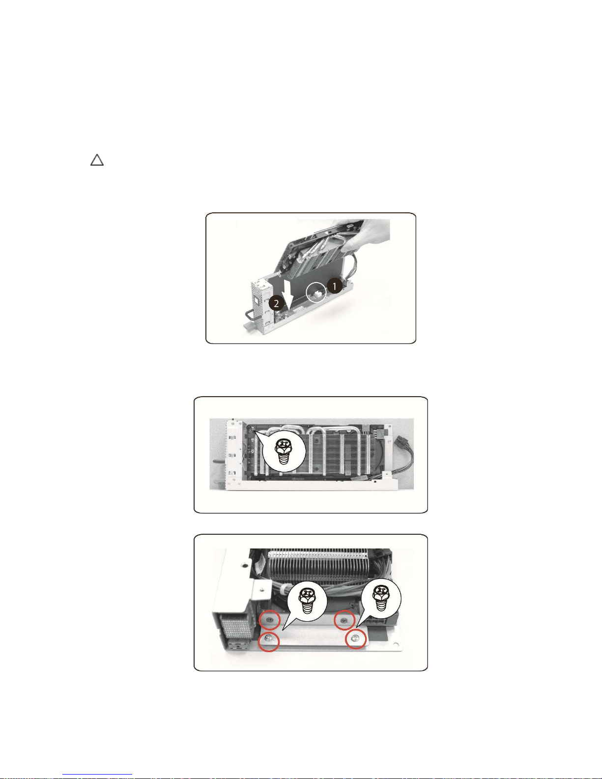
1. Connect PCI power cable.
2. Insert the PCIe card by 45 degree and push it into the socket vertically.
CAUTION: Care should be taken to prevent damage to components on the back side of the PCIe card. Make sure the card does
not drag across the card mounting standoffs of the cage when inserting the card into the socket.
3. Secure the card with screw.
4. Attach the support bracket on the PCIE board and secure it in place with 4 screws.
Removing and Installing Hardware | 20
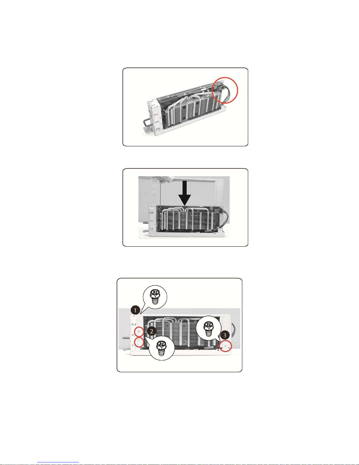
5. Connect power cable to card as shown.
6. Replace the side cover.
7. Secure the side cover with 4 screws
Removing and Installing Hardware | 21
8. Secure the PCIE side cover with 3 screws as illustration arrow show.
Installing the M2050/M2070/M2070Q/M2075/M2090 card
To install the M2050/M2070/M2070Q/M2075 follow the instructions for removing the
M2050/M2070/M2070Q/M2075 in the reverse order.
Removing and Installing Hardware | 22
System Fans
Replacing System Fans
In case of system fan failure, you can quickly replace the system fan.
CAUTION:
Before you remove or install the system fans, take the steps: 1) Make sure the
system is not turned on or connected to the AC power. 2) Disconnect all
necessary cable connections. Failure to observe these warnings could result in
personal injury or damage to the equipment.
Follow the instruction to remove the system fans:
1. Loosen and remove the screws securing the middle cover.
Removing and Installing Hardware | 23
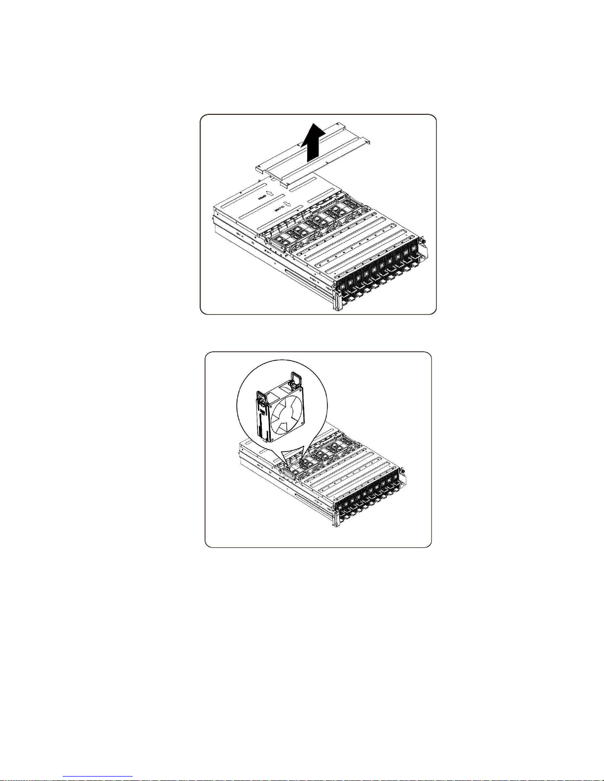
2. Remove the middle top cover from the system.
3. Lift the system fan ears.
Removing and Installing Hardware | 24
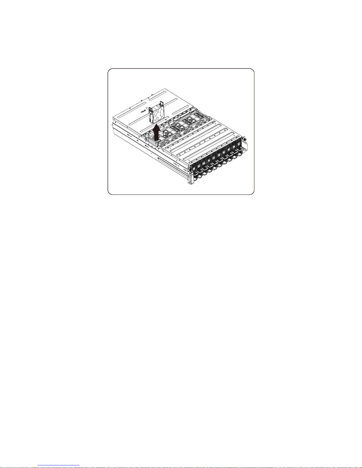
4. Lift the system fan out of the system fan cage.
Installing the system fans
To install the system fans follow the instructions for removing the system fans in the reverse order.
Removing and Installing Hardware | 25
Fan cage
Replacing System Fan Cage
CAUTION:
Before you remove or install the system fan cage, take the steps: 1) Make
sure the system is not turned on or connected to the AC power. 2) Disconnect
all necessary cable connections. Failure to observe these warnings could
result in personal injury or damage to the equipment.
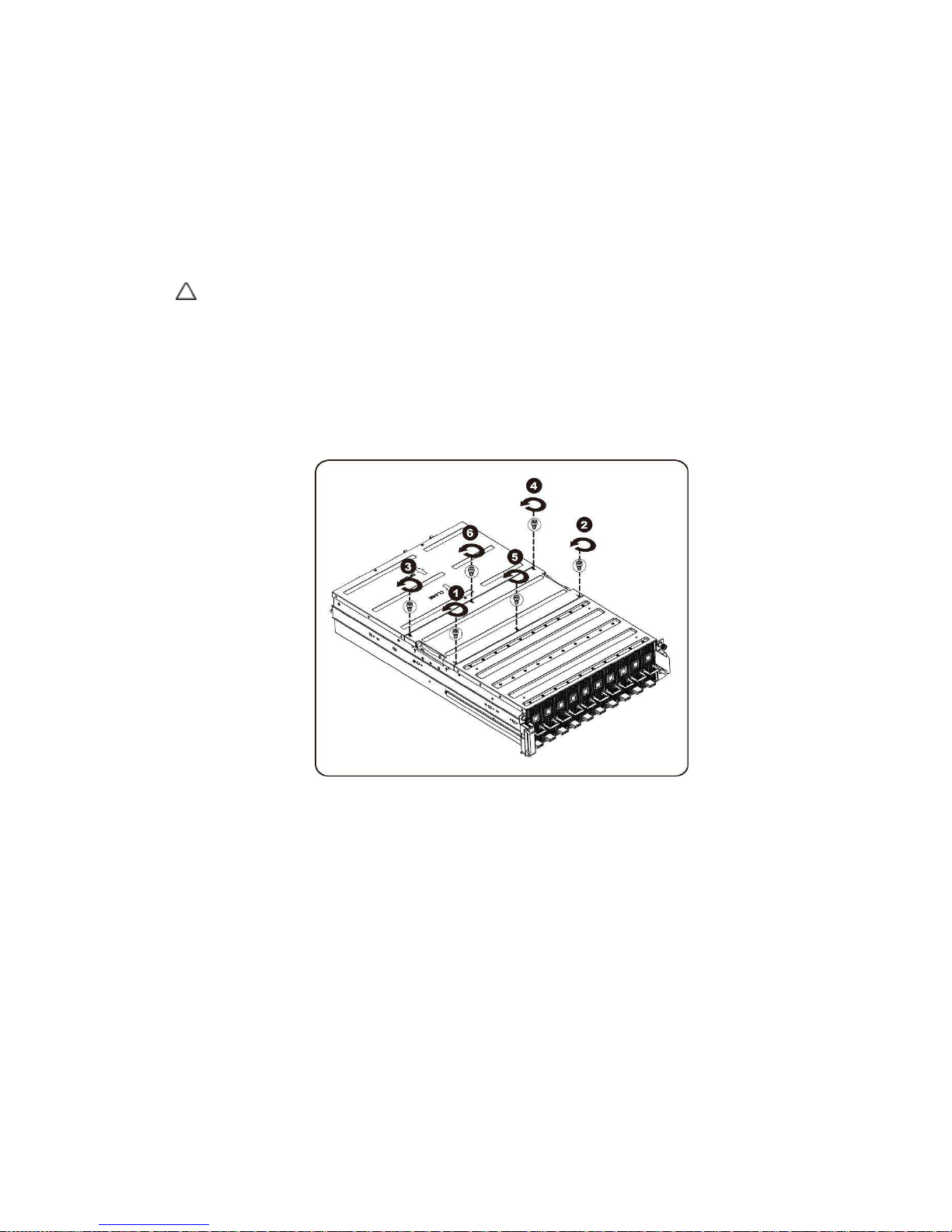
1. Loosen and remove the screws securing the middle cover.
Removing and Installing Hardware | 26
2. Remove the middle top cover from the system.
3. Loosen and remove the screws securing the fan cage.
 Loading...