

Page 1

Dell™PowerEdge™7150SystemsUser'sGuide
System Overview
Computer Orientation
Removing and Replacing the Bezel
Front-Panel Features
Bezel and Control Panel Indicators
Back-Panel Features
System Features
Power Protection Devices
Other Documents You May Need
Safety, Regulatory, and Warranty Information
Getting Help
Using the EFI Boot Manager and Dell Utilities
EFI Boot Manager
Dell Utilities
PowerEdge 7150 System Support CD
Updating or Restoring the System BIOS
Using the System Setup Program
Entering the System Setup Program
System Setup Screens
Using the Password Features
Disabling a Forgotten Password
Technical Specifications
I/O Ports and Connectors
Serial and Parallel Ports
Keyboard and Mouse Connectors
Video Connector
USB Connectors
Integrated Network Interface Controller Connector
Glossary
Figures
Tables
Notes, Notices, Cautions, and Warnings
Model EML
Information in this document is subject to change without notice.
©2000 Dell Computer Corporation. All rights reserved.
Reproduction in any manner whatsoever without the written permission of Dell Computer Corporation is strictly forbidden.
Trademarks used in this text: Dell, the DELL logo, PowerEdge, and Dell OpenManage are trademarks of Dell Computer Corporation; Intel is a registered trademark and Itanium is a trademark of of Intel Corporation; Microsoft is a registered
trademark of Microsoft Corporation.
Other trademarks and trade names may be used in this document to refer to either the entities claiming the marks and names or their products. Dell Computer Corporation disclaims any proprietary interest in trademarks and trade names other than its
own.
Initial release: 13 Dec 2000
NOTE: A NOTE indicates important information that helps you make better use of your computer.
NOTICE: A NOTICE indicates either potential damage to hardware or loss of data and tells you how to avoid the problem.
CAUTION: A CAUTION indicates a potentially hazardous situation which, if not avoided, may result in minor or moderate injury.
WARNING: A WARNING indicates a potentially hazardous situation which, if not avoided, may result in severe injury.
Page 2

Back to Contents Page
Technical Specifications
Dell™PowerEdge™7150SystemsUser'sGuide
Table A-1. Technical Specifications
Microprocessor
Microprocessor type
one to four Intel 64-bit Intel® Itanium™microprocessorswithaminimuminternaloperatingfrequencyof733MHzandanexternal
operating frequency of 133 MHz
Front side bus speed
133 MHz (266 MHz double-pumped)
Internal cache
2- or 4-MB L3 cache
Expansion Bus
Bus type
64-bit PCI
Expansion slots
Eight 66-MHz hot-pluggable slots on six PCI buses; two 33-MHz slots on a seventh PCI bus
Memory
Architecture
registered PC-100-compliant DIMMs with CL2 timing
Memory module sockets
32 sockets per memory board; one or two memory boards
Memory module capacities
128-MB, 256-, or 512-MB; or 1-GB (when available)
Minimum RAM
1 GB
Maximum RAM
64 GB (when 1-GB memory modules are available)
Drives
Diskette drive
one IDE diskette drive
Tape drive
optional external tape drive
SCSI devices
up to four 1-inch, internal, hot-pluggable Ultra3 SCSI hard-disk drives
CD-ROM drive
one IDE CD-ROM drive
Ports and Connectors
Externally accessible:
Serial (DTE)
two 9-pin connectors; 16550-compatible
Parallel
one 25-pin connector (bidirectional)
Video
one 15-pin connector
PS/2-style keyboard
6-pin mini-DIN connector
PS/2-compatible
mouse
6-pin mini-DIN connector
USB
two USB-compliant 4-pin connectors
NIC
RJ45 connector for integrated NIC
SCSI
One 68-pin Ultra3 SCSI connector
ICMB
(Not supported)
Internally accessible:
IDE channels
two 40-pin connectors
SCSI channels
two 68-pin Ultra3 SCSI connectors
Video
Video type
ATI Rage 128 XL video controller; VGA connector
Video memory (standard)
8 MB
Power1
DC power supply:
Wattage
four 800 W power supplies in a 3 +1 redundant configuration
Voltage
200-240V, 50/60 Hz
optional 100-240V, 50/60 Hz
System battery
CR2032 3.0-V lithium coin cell
Page 3

Back to Contents Page
Physical
Height
31.12 cm (12.25 inches [7 U])
Width
44.45 cm (17.5 inches)
Depth
71.12 cm (28.0 inches)
Weight
72.5 kg (160 lb), maximum configuration
Environmental
Temperature: Operating
10°to35°C(50°to95°F)
Storage
-40°to65°C2 (-40°to149°F)
Relative humidity:
Operating
85%(noncondensingat40°C[104°F])
Storage
95%(noncondensingat55°C[131°F])
NOTE: 1 Under typical line conditions and over the entire system ambient operating range, the inrush current may reach 140A.
NOTE:
2
Limitthenumberoftransitionsacross0°Ctonomorethan50.
NOTE: For the full name of an abbreviation or acronym used in this table, see the Glossary.
Page 4
Back to Contents Page
I/O Ports and Connectors
Dell™PowerEdge™7150SystemsUser'sGuide
Serial and Parallel Ports
Keyboard and Mouse Connectors
Video Connector
USB Connectors
Integrated Network Interface Controller Connector
This section provides specific information about the computer's I/O ports.
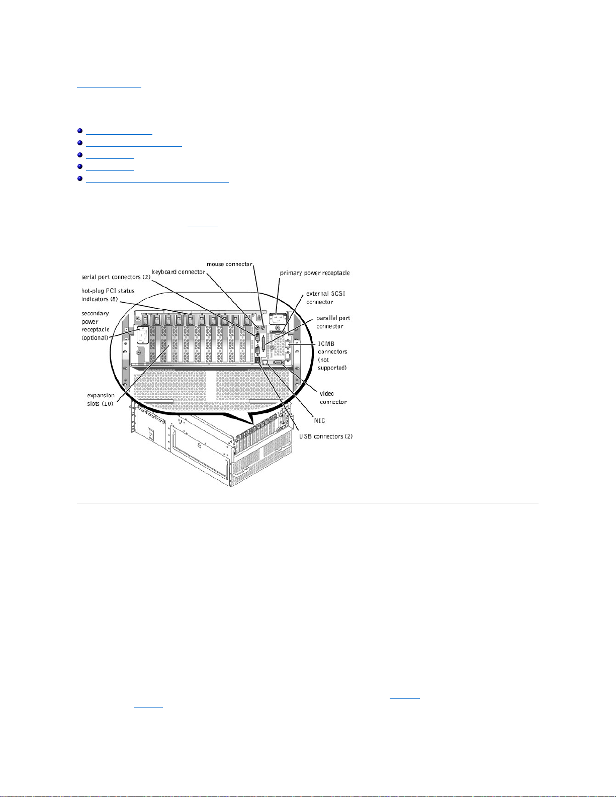
The I/O ports and connectors on the back panel of the computer are the gateways through which the computer system communicates with external devices, such as a
keyboard, mouse, printer, and monitor. FigureB-1 identifies the I/O ports and connectors for your system.
Figure B-1. Back-Panel Features
Serial and Parallel Ports
The two integrated serial ports use 9-pin D-subminiature connectors on the back panel. These ports support devices such as external modems, printers, plotters, and
mice that require serial data transmission (the transmission of data one bit at a time over one line).
Most software uses the term COM (for communications) plus a number to designate a serial port (for example, COM1 or COM2). The default designations of your
computer'sintegratedserialportsareCOM1andCOM2.
The integrated parallel port uses a 25-pin D-subminiature connector on the computer's back panel. This I/O port sends data in parallel format (where eight data bits, or
one byte, are sent simultaneously over eight separate lines in a single cable). The parallel port is used primarily for printers.
Most software uses the term LPT (for line printer) plus a number to designate a parallel port (for example, LPT1). The default designation of the computer's integrated
parallel port is LPT1.
Port designations are used, for example, in software installation procedures that include a step in which you identify the port to which a printer is attached, thus telling
the software where to send its output. (An incorrect designation prevents the printer from printing or causes scrambled print.)
Serial Port Connectors
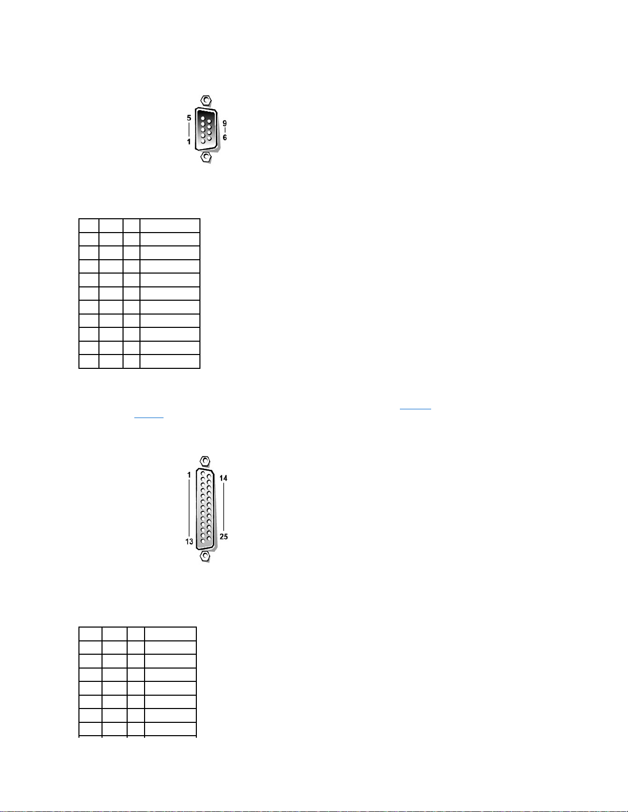
If you reconfigure your hardware, you may need pin number and signal information for the serial port connectors. FigureB-2 illustrates the pin numbers for the serial
port connectors and TableB-1 defines the pin assignments and interface signals for the serial port connector.
Figure B-2. Pin Numbers for the Serial Port Connectors
Page 5
Parallel Port Connector
If you reconfigure your hardware, you may need pin number and signal information for the parallel port connector. FigureB-3 illustrates the pin numbers for the parallel
port connector and TableB-2 defines the pin assignments and interface signals for the parallel port connector.
Figure B-3. Pin Numbers for the Parallel Port Connector
Table B-1. Pin Numbers for the Serial Port
Connectors
Pin
Signal
I/O
Definition
1
DCD I Data carrier detect
2
SIN I Serial input
3
SOUT
O
Serial output
4
DTR O Data terminal ready
5
GND
N/A
Signal ground
6
DSR I Data set ready
7
RTS O Request to send
8
CTS I Clear to send
9
RI I Ring indicator
Shell
N/A
N/A
Chassis ground
Table B-2. Parallel Port Pin Assignments
Pin
Signal
I/O
Definition
1
STB#
I/O
Strobe
2
PD0
I/O
Printer data bit 0
3
PD1
I/O
Printer data bit 1
4
PD2
I/O
Printer data bit 2
5
PD3
I/O
Printer data bit 3
6
PD4
I/O
Printer data bit 4
7
PD5
I/O
Printer data bit 5
Page 6
Keyboard and Mouse Connectors
The system uses a Personal System/2 (PS/2)-style keyboard and supports a
PS/2-compatible mouse. Cables from both devices attach to 6-pin, miniature Deutsche Industrie Norm (DIN) connectors on the back panel of your computer.
Mouse driver software can give the mouse priority with the microprocessor by issuing IRQ12 whenever a new mouse movement is detected. The driver software also
passes along the mouse data to the application program that is in control.
Keyboard Connector
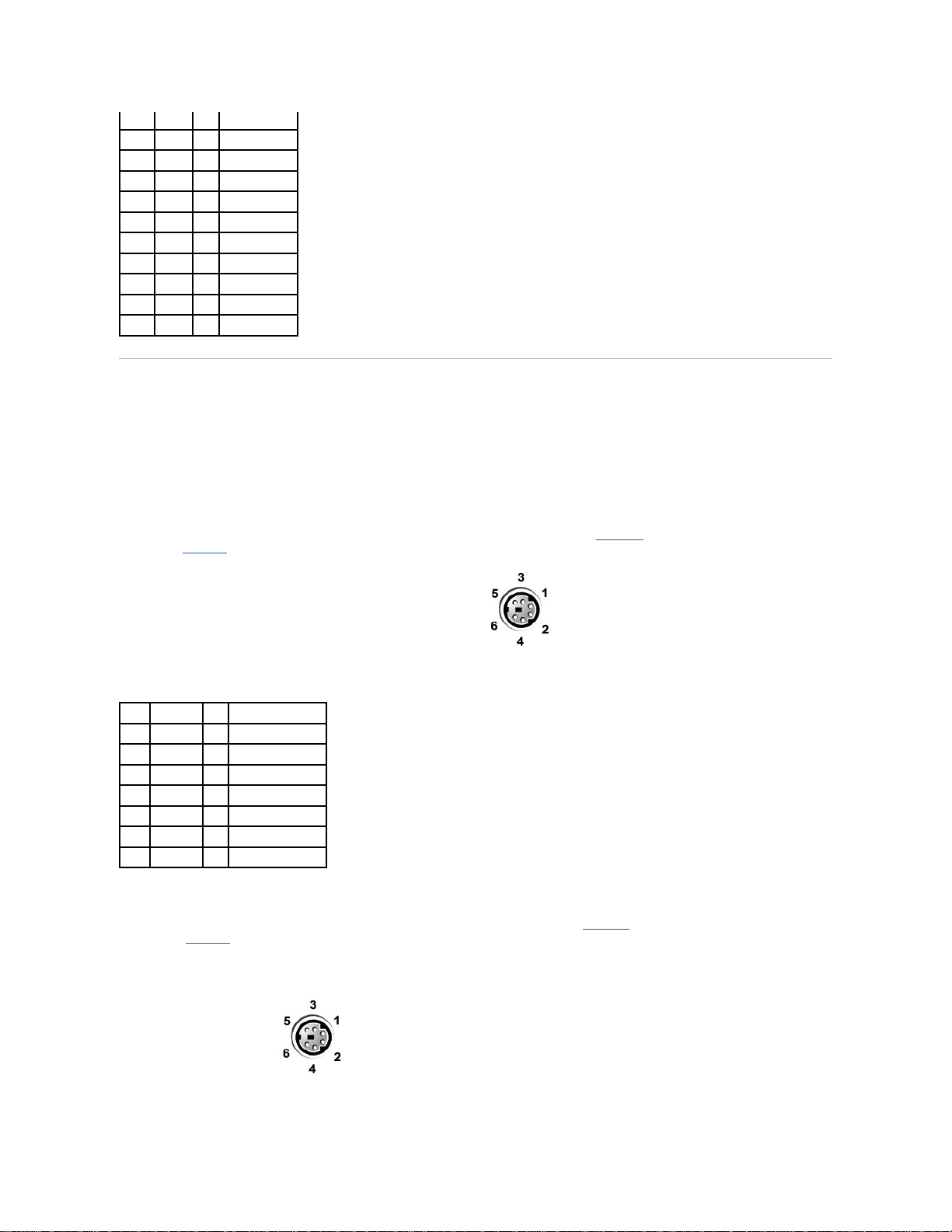
If you reconfigure your hardware, you may need pin number and signal information for the keyboard connector. FigureB-4 illustrates the pin numbers for the keyboard
connector and TableB-3 defines the pin assignments and interface signals for the keyboard connector.
Figure B-4. Pin Numbers for the Keyboard Connector
Mouse Connector
If you reconfigure your hardware, you may need pin number and signal information for the mouse connector. FigureB-5 illustrates the pin numbers for the mouse
connector, and TableB-4 defines the pin assignments and interface signals for the mouse connector.
Figure B-5. Pin Numbers for the Mouse Connector
8
PD6
I/O
Printer data bit 6
9
PD7
I/O
Printer data bit 7
10
ACK#
I Acknowledge
11
BUSY
I
Busy
12
PE I Paper end
13
SLCT I Select
14
AFD#
O
Automatic feed
15
ERR#
I
Error
16
INIT#
O
Initialize printer
17
SLIN#
O
Select in
18–25
GND
N/A
Signalground
Table B-3.KeyboardConnectorPinAssignments
Pin
Signal
I/O
Definition
1
KBDATA
I/O
Keyboard data
2
NC
N/A
No connection
3
GND
N/A
Signal ground
4
FVcc
N/A
Fused supply voltage
5
KBCLK
I/O
Keyboard clock
6
NC
N/A
No connection
Shell
N/A
N/A
Chassis ground
Page 7
Video Connector
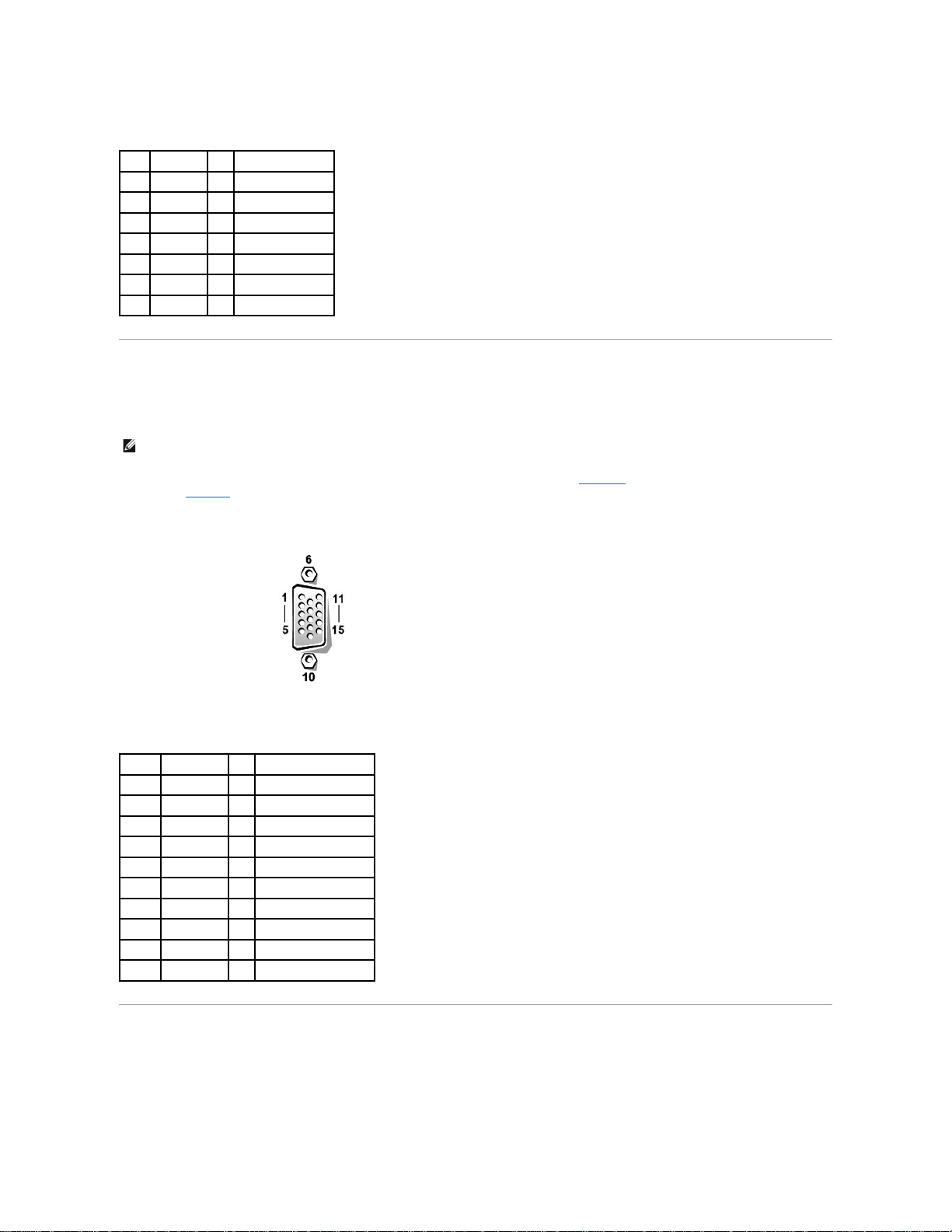
The system uses a 15-pin high-density D-subminiature connector on the back panel for attaching a video graphics array (VGA)-compatible monitor to your computer.
The video circuitry on the system board synchronizes the signals that drive the red, green, and blue electron guns in the monitor.
If you reconfigure your hardware, you may need pin number and signal information for the video connector. FigureB-6 illustrates the pin numbers for the video
connector, and TableB-5 defines the pin assignments and interface signals for the video connector.
Figure B-6. Pin Numbers for the Video Connector
USB Connectors
Your system contains two USB connectors for attaching USB-compliant devices. USB devices are typically peripherals such as mice, printers, keyboards, and
computer speakers.
Table B-4.MouseConnectorPinAssignments
Pin
Signal
I/O
Definition
1
MCDATA
I/O
Mouse data
2
NC
N/A
No connection
3
GND
N/A
Signal ground
4
FVcc
N/A
Fusedsupplyvoltage
5
MCCLK
I/O
Mouse clock
6
NC
N/A
No connection
Shell
N/A
N/A
Chassis ground
NOTE: Installing a video card automatically disables the system's integrated video subsystem.
Table B-5. Video Connector Pin Assignments
Pin
Signal
I/O
Definition
1
RED O Red video
2
GREEN
O
Green video
3
BLUE O Blue video
4
NC
N/A
No connection
5–8, 10
GND
N/A
Signal ground
9
VCC
N/A
Vcc
11
NC
N/A
No connection
12
DDC data out
O
Monitor detect data
13
HSYNC
O
Horizontal synchronization
14
VSYNC
O
Vertical synchronization
Page 8
If you reconfigure your hardware, you may need pin number and signal information for the USB connectors. FigureB-7 illustrates the USB connector and TableB-6
defines the pin assignments and interface signals for the USB connector.
Figure B-7. Pin Numbers for the USB Connector
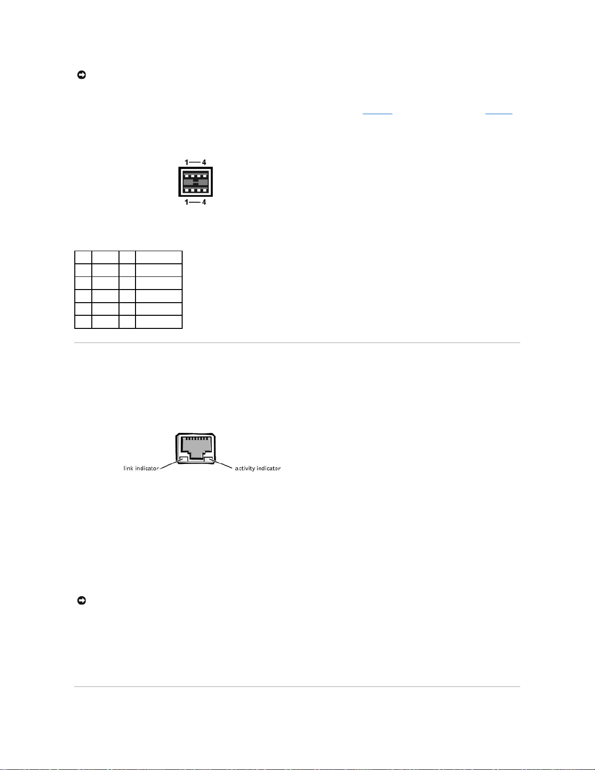
Integrated Network Interface Controller Connector
Your system has an integrated 10/100–Mbps NIC. The NIC provides all the functions of a separate network expansion card and supports both the 10BASE-T and
100BASE-TX Ethernet standards.
Figure B-8. NIC Connector
The NIC includes a Wake On LAN (WOL) feature that enables the computer to be started by a special LAN signal from a server management console. WOL
provides remote computer setup, software downloading and installation, file updates, and asset tracking after hours and on weekends when LAN traffic is typically at a
minimum.
Network Cable Requirements
Your computer's RJ45 NIC connector is designed for attaching an unshielded twisted pair (UTP) Ethernet cable equipped with standard RJ45-compatible plugs. Press
one end of the UTP cable into the NIC connector until the plug snaps securely into place. Connect the other end of the cable to an RJ45 jack wall plate or to an RJ45
port on a UTP concentrator or hub, depending on your network configuration. Observe the following cabling restrictions for 10BASE-T and 100BASE-TX networks.
l For 10BASE-T networks, use Category 3 or greater wiring and connectors.
l For 100BASE-TX networks, use Category 5 or greater wiring and connectors.
l Themaximumcablerunlength(fromaworkstationtoaconcentrator)is328ft(100m).
l For 10BASE-T networks, the maximum number of daisy-chained concentrators on one network segment is four.
NOTICE: Do not attach a USB device or a combination of USB devices that draw a maximum current over 500 mA per channel or +5 V. Attaching devices
that exceed this threshold might cause the USB ports to shut down. See the documentation that accompanied the USB devices for their maximum current
ratings.
Table B-6.USBConnectorPinAssignments
Pin
Signal
I/O
Definition
1
Vcc
N/A
Supply voltage
2
-DATA
I/O
Differential data
3
+DATA
I/O
Differential data
4
GND
N/A
Signal ground
Shell
N/A
N/A
Chassis ground
NOTICE: To avoid line interference, voice and data lines must be in separate sheaths.
Page 9

Back to Contents Page
Page 10
Back to Contents Page
System Overview
Dell™PowerEdge™7150SystemsUser'sGuide
TheDell™PowerEdge™7150systemisafeature-rich, enterprise-class server that offers the highest performance, availability, scalability, manageability, and
investment protection features. This system provides a robust, reliable, rack-optimized platform on which corporate customers can deploy their mission-critical
applications.
This section describes the major hardware and software features of the computer system, provides information about the indicators on the system's bezel and control
panel, and discusses connecting external devices to the system. It also provides information on obtaining assistance from Dell.
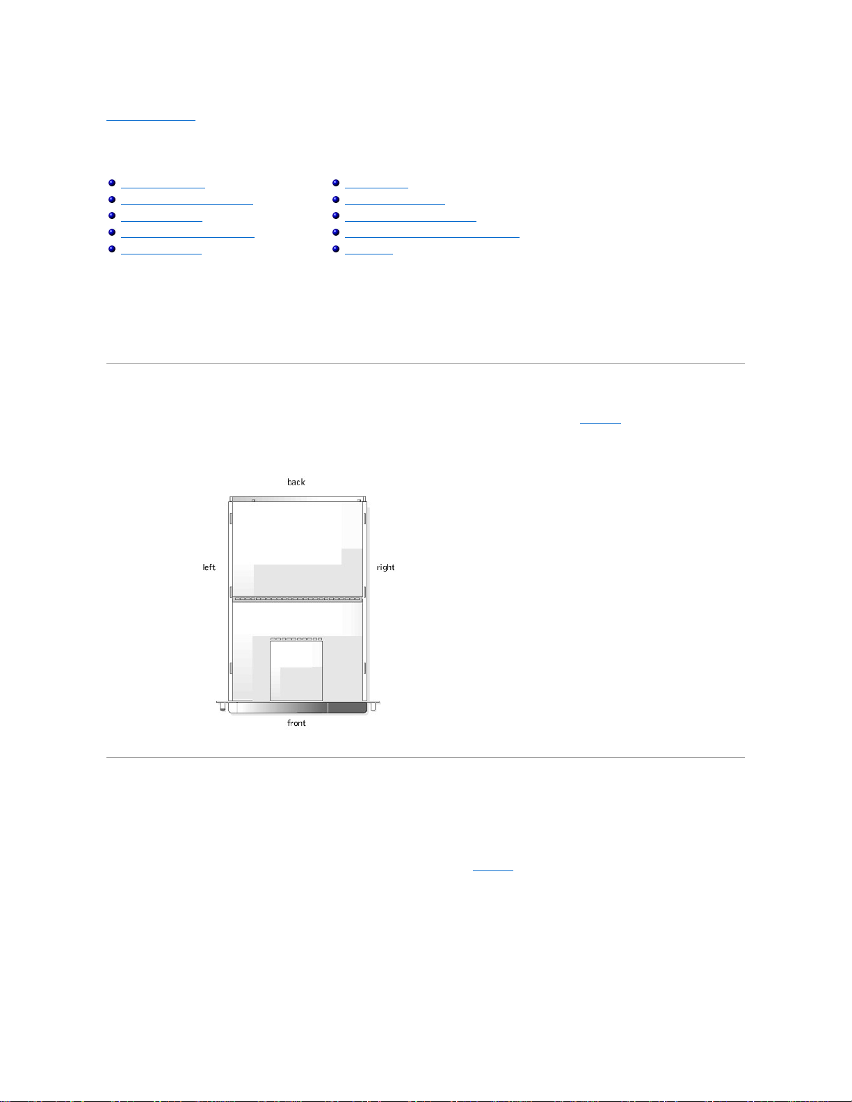
Computer Orientation
When following the procedures in this guide, assume that the locations or directions relative to the computer are as shown in Figure1-1.
Figure 1-1. Computer Orientation (top view)
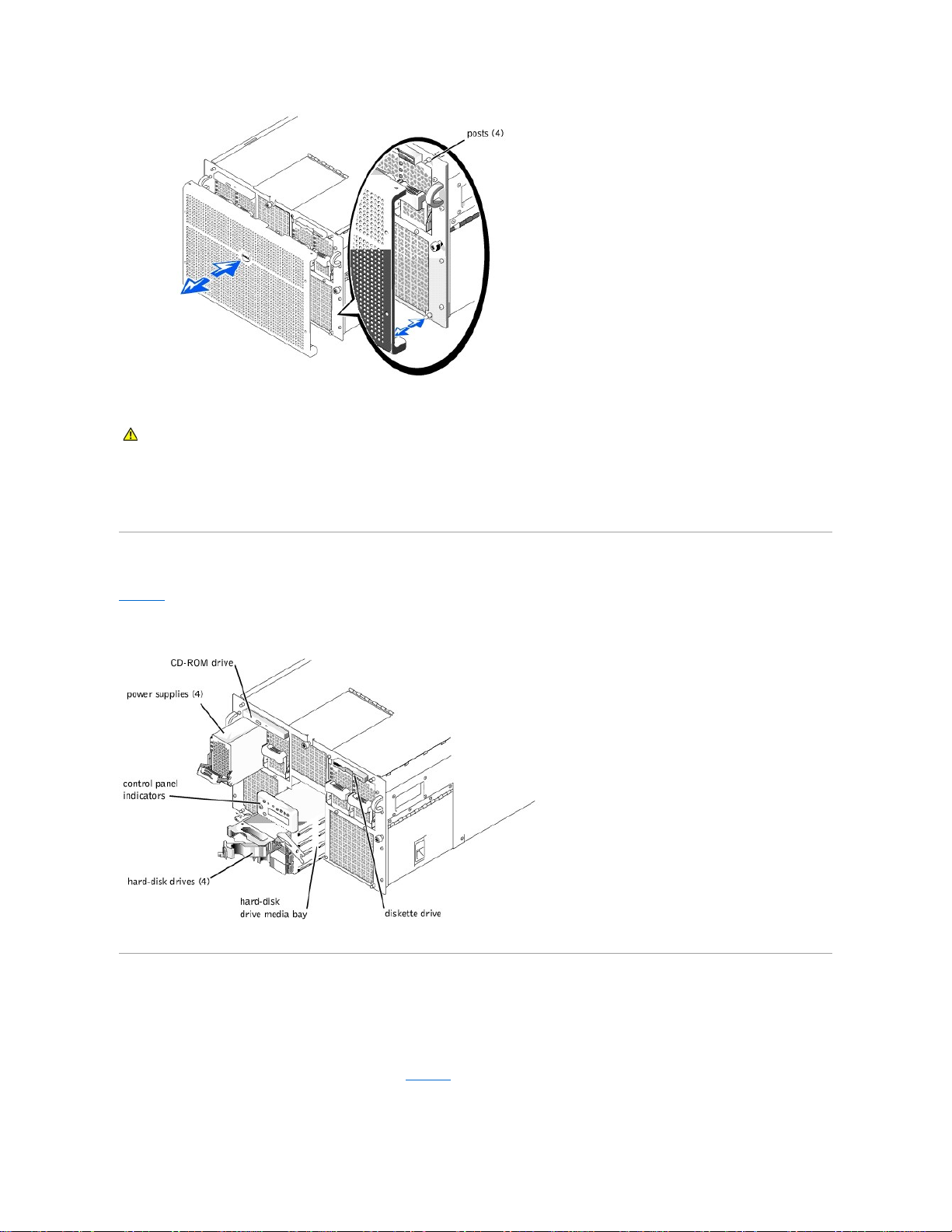
Removing and Replacing the Bezel
Removing the front bezel provides access to the power switch, diskette drive, control panel, CD-ROM drive, power supplies, and hard-disk drive(s).
Removing the Bezel
Pull the bezel away from the computer until it disengages from the four posts on the chassis (see Figure1-2).
Figure 1-2. Removing the Bezel
Computer Orientation
Removing and Replacing the Bezel
Front-Panel Features
Bezel and Control Panel Indicators
Back-Panel Features
System Features
Power Protection Devices
Other Documents You May Need
Safety, Regulatory, and Warranty Information
Getting Help
Page 11
Replacing the Bezel
1. Align the four notches and the connector on the back of the bezel with the four posts and connector on the front of the system.
2. Gently press the bezel onto the front of the computer until it snaps into place.
Front-Panel Features
Figure1-3 shows the major features at the front of the computer.
Figure 1-3. Front-Panel Features
Bezel and Control Panel Indicators
The system bezel and control panel both have indicators to provide you with information on the system's status.
Bezel Indicators
When the bezel is in place on the system, it has two indicators (see Figure1-4). The Dell logo lights blue when the system is operating correctly. The caution icon lights
amber when the system needs attention. The amber caution light indicates a power problem, a fan/temperature problem, a hard drive problem, or that the PCI
expansion cards need attention. Remove the bezel to determine the source of the problem.
CAUTION: When reinstalling the front bezel, carefully align the bezel to avoid damaging the connector on the back which operates the indicator
lights on the front of the bezel.
Page 12
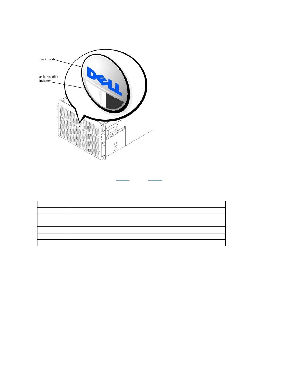
Figure 1-4. Bezel Indicators
Control-Panel Indicators
The indicators on the computer's control panel described in Table1-1 are shown in Figure1-5:
Figure 1-5. Control-Panel Indicators
Table 1-1. Control-Panel Indicators
Indicator
Function
Power
Green when the power supplies are turned on and the system is receiving power
Power-Supply Status
Amber if a fault is detected with any of the power supplies, any system voltages, or redundant AC power line failure
Fan Status
Amber when a fan failure is detected or temperature is out of bounds
PCI Slot Attention
Amber when one or more or the PCI slots need attention.
Hard-disk drive fault
Amber if a problem occurs with one of the internal hard-disk drives
Display
System information messages during POST
Page 13

Back-Panel Features
Figure1-6 shows the back-panel features on the computer.
Figure 1-6. Back-Panel Features
When connecting external devices to your system, follow these guidelines:
l Always attach external devices while your system is turned off and the AC power cords are unplugged. Turn on any external devices before turning on the
Page 14

system unless the documentation for the device specifies otherwise. (If the system does not seem to recognize the device, try turning on the system before turning
on the device.)
l Check the documentation that accompanied the device for specific installation and configuration instructions. For example, most devices must be connected to a
particular connector to operate properly. Also, external devices usually require you to install device drivers before they will work. Device drivers are normally
included with your operating system software, or with the device itself.
For information about enabling, disabling, or configuring I/O ports and connectors, see "Using the System Setup Program" or "I/O Ports and Connectors."
System Features
Your PowerEdge system offers the following features:
l One to four Intel
®
Itanium™ microprocessors.
l Front-side bus speed of 133 MHz (266 MHz double-pumped).
l Level 3 cache of 2 or 4 MB.
l Support for symmetric multiprocessing (SMP), which is available by installing up to three additional microprocessors.
l A minimum of 1 GB of system memory, upgradable to a maximum of 64 GB by installing combinations of 128-, 256-, or 512-MB or 1-GB (when available)
registered SDRAM memory modules in the 32 sockets on each of the two memory boards. The system supports 4-way interleaving if specific memory
configurations are used.
l Support for up to four 1-inch, internal, hot-pluggable Ultra SCSI hard-disk drives via a 1 x 4 or 2 x 2 SCSI backplane board and hard-disk drive carriers.
l Four hot-pluggable, 800 W power supplies in a 3 + 1 redundant configuration.
l An optional redundant 208-V power module.
l Six redundant, hot-pluggable system cooling fans.
The system's I/O board includes the following built-in features:
l Ten 64-bit, PCI expansion-card connectors on seven PCI buses. Eight of the expansion slots operate at 66 or 33 MHz and are hot-pluggable. These expansion
slots accommodate 3.3V or Universal (3.3 or 5V) expansion cards. The two remaining expansion slots operate at 33 MHz and are not hot-pluggable. You can
install 5V or Universal PCI cards in these two expansion slots. (An eleventh expansion slot is reserved for use by the system's I/O riser board.)
l AvideosubsystembasedontheATIRage128XLvideocontroller.Thisvideosubsystemresidesonthe33MHzPCIbusandcontains8MBofvideo
memory(notupgradable).Maximumresolutionsare1280x1024with256colorsnoninterlaced.In800x600and640x480resolutions,16.7millioncolors
are available for true-color graphics.
l Ultra3 SCSI device support via an integrated QLogic ISP12160A dual-channel controller.
l An integrated Intel 10/100 NIC, which provides an external Ethernet interface.
l Server management circuitry that monitors the operation of the system fans as well as critical system voltages and temperatures.
Standard systems include an IDE CD-ROM drive and a diskette drive installed in the externally accessible bays.
The following software is included with your Dell system:
l A system setup program for quickly viewing and changing the system configuration information for your system. For more information on this program, see
"Using the System Setup Program"
l An Extensible Firmware Interface (EFI) Boot Manager program which lets you access the EFI Shell command line prompt, a boot manager utility, and the Dell
Utilities.
l Enhanced security features, including chassis intrusion monitoring and a user password and a supervisor password, available through the system setup program.
l Dell Diagnostics for evaluating your system's components and devices. For information on using the system diagnostics, see "Running the Dell Diagnostics" in
your Installation and Troubleshooting Guide.
NOTE: If you decide to upgrade your system by installing additional microprocessors, you must order the microprocessor upgrade kits from Dell. Not all
versions of the microprocessor will work properly as additional microprocessors. The upgrade kit from Dell contains the correct version of the
microprocessor as well as the correct instructions for performing the upgrade. All microprocessors must have the same internal operating frequency and
cache size.
Page 15

Power Protection Devices
A number of devices are available that protect against potential power problems such as power surges, transients, and power failures. The following subsections
describe some of these devices.
Surge Protectors
Surge protectors are available in a variety of types and usually provide a level of protection commensurate with the cost of the device. Surge protectors prevent voltage
spikes, such as those caused during an electrical storm, from entering a system through the electrical outlet. Surge protectors, however, do not offer protection against
brownouts, which occur when the voltage drops more than 20 percent below the normal AC line voltage level.
Line Conditioners
Line conditioners go beyond the overvoltage protection of surge protectors. Line conditioners keep a system's AC power source voltage at a fairly constant level and,
therefore, can handle brownouts. Because of this added protection, line conditioners cost more than surge protectors—up to several hundred dollars. However, these
devices cannot protect against a complete loss of power.
Uninterruptible Power Supplies
UPS systems offer the most complete protection against variations in power because they use battery power to keep the system running when AC power is lost. The
battery is charged by the AC power while it is available, so once AC power is lost, the battery can provide power to the system for a limited amount of time—from 15
minutes to an hour or so—depending on the UPS system.
UPS systems range in price from a few hundred dollars to several thousand dollars, with the more expensive units allowing you to run larger systems for a longer period
of time when AC power is lost. UPS systems that provide only 5 minutes of battery power let you conduct an orderly shutdown of the system, but are not intended to
provide continued operation. Surge protectors should be used with all UPS systems, and the UPS system should be UL safety-approved.
Other Documents You May Need
Besides this User's Guide, the following documentation is included with your system:
l The Setting Up Your System sheet provides general instructions for setting up your computer system.
l Dell PowerEdge 7150 Systems Installation and Troubleshooting Guide
l Dell PowerEdge System Information document for important safety, regulatory, and warranty information
l Dell PowerEdge 7150 Systems Rack Installation Guide
You might also have one or more of the following documents:
l Operating system documentation is included if you ordered your operating system software from Dell. This documentation describes how to install (if necessary),
configure, and use your operating system software.
l Documentation is included with any options you purchase separately from your system. This documentation includes information that you need to install and
configure these options in your Dell system. Installation instructions for the options are included in this User's Guide.
l Technical information files—sometimes called "readme" files—may be installed on your hard-disk drive to provide last-minute updates about technical changes
to your system or advanced technical reference material intended for experienced users or technicians.
Safety, Regulatory, and Warranty Information
For safety, regulatory, and warranty information for your system, see the System Information document included with your system.
Getting Help
If at any time you don't understand a procedure described in this guide or if your system does not perform as expected, Dell provides a number of tools to help you.
For more information on these help tools, see "Getting Help" in your Installation and Troubleshooting Guide.
Back to Contents Page
NOTE: Documentation updates are sometimes included with your system to describe changes to your system or software. Always read these updates before
consulting any other documentation because the updates often contain the latest information.
Page 16

Page 17

Back to Contents Page
Using the EFI Boot Manager and Dell Utilities
Dell™PowerEdge™7150SystemsUser'sGuide
EFI Boot Manager
Dell Utilities
PowerEdge 7150 System Support CD
Updating or Restoring the System BIOS
This section describes your system's Extensible Firmware Interface (EFI) Boot Manager program, the PowerEdge 7150 System Support CD, and the Dell Utilities
program. They provide access to various utilities which you may use to configure your system.
EFI Boot Manager
The EFI Boot Manager menu lets you access the operating systems installed on your system, a boot manager utility, and the Utilities menu.
Entering the EFI Boot Manager
1. Turn on your system by pressing the power button on the system front panel.
If your system is already on, reboot it.
2. Wait until the system tests are completed.
The EFI Boot Manager screen appears.
Selecting EFI Boot Manager Options
From the EFI Boot Manager screen, you can select the following options:
l Operating systems installed on your system
l Boot Option Maintenance Manager Menu — Use this option to select which devices the system can be booted from, and their relative order.
l Utilities — Select this option to go to the Utilities Option Menu. For more information on this menu, see "Utilities Option Menu."
Utilities Option Menu
This menu includes the following options:
l EFI Shell — Use this option to run command-driven programs from the Shell prompt.
l Dell Utilities — Select this option to run the Dell Utilities program. See "Dell Utilities" for more information on this program.
l BIOS Update — Select this option to update the system BIOS to the latest version. See "Updating or Restoring the System BIOS" for more information on this
program.
l Firmware Update — Select this option to update the system firmware to the latest version.
l Run Dell Diagnostics from diskette — Select this option to run the system hardware diagnostics. (For more information, see "Running the Dell Diagnostics" in
your Installation and Troubleshooting Guide.)
Dell Utilities
The Dell Utilities include the Dell Diagnostics program, as well as features that can help you configure your system to best meet your needs. You run the utilities from
an EFI System Partition that you can create on the system boot hard-disk drive, using the PowerEdge 7150 System Support CD. (See "PowerEdge 7150 System
Support CD" for more information on this CD.)
Starting the Dell Utilities
If you have created an EFI System Partition on the system's boot hard-disk drive and installed the utilities on this partition, you can run the Dell Utilities. To run the Dell
Utilities from the hard-disk drive, perform the following steps:
1. Turn on your system by pressing the power button on the system front panel.
Page 18

If your system is already on, reboot it.
2. Wait until the system tests are completed.
The EFI Boot Manager screen appears.
3. From the EFI Boot Manager main menu, select Utilities.
4. From the Utilities Options menu, select Dell Utilities.
Selecting Dell Utilities Options
From the Dell Utilities menu, you can select options to perform the following tasks:
l Run the Dell Diagnostics program (The system hardware diagnostics are described in "Running the Dell Diagnostics" in your Installation and Troubleshooting
Guide.)
l Assign or change an asset tag number for your system. An asset tag number can have up to ten characters; any combination of characters, excluding spaces, is
valid.
l Run the System Event Log (SEL) Viewer
PowerEdge 7150 System Support CD
To access the utilities, drivers, and other items available on the PowerEdge 7150 System Support CD, insert the CD into the system's CD-ROM drive, and turn on or
reboot the system.
PowerEdge 7150 System Support CD Options
From the main menu, you can select options to perform the following tasks:
l Create an EFI System Partition on the boot hard-disk drive
l Copy the Dell Utilities to the EFI System Partition
l Copy drivers or system utilities to a diskette
l Run the Dell Diagnostics program (The system hardware diagnostics are described in "Running the Dell Diagnostics" in your Installation and Troubleshooting
Guide.)
Updating or Restoring the System BIOS
If necessary, you can restore the system BIOS or update the system BIOS to the latest version.
1. Before updating the BIOS, run the system setup program and note any option settings that vary from the default settings.
2. Download the updated BIOS files from http://support.dell.com onto the BIOS recovery diskette provided with your system.
3. Insert the BIOS recovery diskette into the diskette drive and reboot the system.
4. From the EFI Boot Manager menu, select the Utilities option.
5. Select the BIOS Update option and follow the on-screen instructions.
The system reboots automatically after the update process is completed.
6. Enter the system setup program by pressing <F2> when the Dell logo is displayed, and restore the options to their original settings.
Back to Contents Page
NOTE: If the CD does not boot, verify that the CD-ROM drive is specified in the boot sequence option in the EFI Boot Maintenance Manager program.
Page 19

Page 20

Back to Contents Page
Using the System Setup Program
Dell™PowerEdge™7150SystemsUser'sGuide
Entering the System Setup Program
System Setup Screens
Using the Password Features
Disabling a Forgotten Password
You can use the system setup program as follows:
l To change the system configuration information after you add, change, or remove hardware in your system
l To set or change user-selectable options—forexample,thetimeordateonyoursystem
l To configure integrated devices in your system
After you set up your system, run the system setup program to familiarize yourself with your system configuration information and optional settings. Dell recommends
that you record this information for future reference.
Entering the System Setup Program
1. Turn on your system by pressing the power button on the system front panel.
If your system is already on, shut it down and then turn it on again.
2. Press <F2> immediately after the Dell logo is displayed.
If you wait too long and your operating system begins to load into memory, let the system complete the load operation; shut down the system and try again.
You can also enter the system setup program by responding to certain error messages. See "Responding to Error Messages."
Responding to Error Messages
If an error message appears on your monitor screen while the system is booting, make a note of the message. Then, before entering the system setup program, see
"System Beep Codes" and "System Messages" in your Installation and Troubleshooting Guide for an explanation of the message and suggestions for correcting any
errors. (An exception to this routine: It is normal to receive an error message the first time you boot your system after installing a memory upgrade. In that situation, do
not refer to "System Beep Codes" and "System Messages." Instead, follow the instructions for performing a memory upgrade in "Adding Memory" in your Installation
and Troubleshooting Guide.)
If you are given an option of pressing either <F1> to continue or <F2> to run the system setup program, press <F2>.
Using the System Setup Program
Table3-1 lists the keys that you use to view or change information on the system setup screens and to exit the program.
.
NOTE: To ensure an orderly system shutdown, consult the documentation that accompanied your operating system.
Table 3-1.SystemSetupNavigationKeys
Keys
Action
Left and Right Arrows
Scrolls through the five main menu screens
<Enter>
Selects a menu option
Up and Down arrows
Scrolls through menu items or options in a field
<Esc>
Exits the system setup program without changing values
<F9>
Restores default values for all system setup program fields
<F10>
Saves changes and exits the system setup program
<Tab>
Used to to select a field within the date and time options
Page 21

System Setup Screens
The system setup screens display the current setup and configuration information for your system. You can select the following five primary screens:
l Main — displays the BIOS version, microprocessor type, and default system setup screen language. You can also set the system time and date and processor
retest option from this screen.
l Advanced — displays a screen with five submenu items (Boot Configuration, Peripheral Configuration, IDE Configuration, Chipset Configuration, and
Event Log Configuration). See "Advanced Menu Screen" for information on these submenus.
l Security — displays a screen which allows you to configure the user password and supervisor password features. See "Using the Password Features" and
"Using the Supervisor Password Feature."
l Boot — displays the Boot screen which allows you to specify the boot order of devices in the system. See "Boot Screen" for more information on these
options.
l System Management — displays a screen with two submenu items (Console Redirection and Server Boot).
l Exit — displays the Exit screen. See "Exit Screen."
Main Menu Screen
The Main Menu screen displays the BIOS version, microprocessor, and default BIOS language. You can also set the system time and date from this screen.
Advanced Menu Screen
You can select from the following five submenus from the Advanced Menu screen described in the subsections that follow.
Boot Configuration Submenu
The Boot Configuration submenu options configure several boot settings, including the presence of a Plug and Play operating system and the status of the keyboard
keypad. (To change the system startup boot order, use the Boot screen, described later in this section.)
Peripheral Configuration Submenu
You can use this submenu to configure the following devices:
l Serial Port A, Serial Port B — Configures the system's integrated serial ports. These options can be set to Auto (the default) to automatically configure a port,
to Enable to select a particular address and interrupt value, or to Disable.
l Serial Port Mode — Configures the transfer mode for the system's integrated serial ports. To determine the correct mode to use, see the documentation that
came with the peripheral device connected to the serial ports.
l Parallel Port— Configures the system's integrated parallel port.
l Parallel Port Mode — Configures the transfer mode for the system's integrated parallel port. To determine the correct mode to use, see the documentation that
came with the peripheral device connected to the parallel port.
l Onboard SCSI — Enables the system's integrated SCSI controller.
l Onboard NIC — Enables the system's integrated NIC.
IDE Configuration Submenu
Use this submenu to configure the system's integrated IDE controller and any IDE devices in the system, such as the diskette drive or CD-ROM drive.
Chipset Configuration Submenu
To avoid possible system degradation, do not change the settings in this menu's options from their default values.
Event Log Configuration
Use this submenu to enable or disable system event logging, view the event log, mark events as read, or clear event log entries.
Security Screen
This screen displays the current status of the supervisor password and the user password. The user password protects against unauthorized access to your system; the
supervisor password protects against unauthorized changes to the system setup program.
If the supervisor password is not enabled, you can set these two passwords using the Set Supervisor Password and Set User Password options.
Page 22

The Security Screen also allows you to enable and configure the Secure Mode option. When the system is in Secure Mode, most input and output devices are disabled
until you enter the user password. You can modify the Security Screen settings to activate Secure Mode after a period of inactivity, at system boot, after a period of
system inactivity, or by pressing a key sequence that you define using a Security Screen option.
Boot Screen
The Boot Screen options determine the boot search order for devices connected to the system. Available options include the diskette drive, hard-disk drives, CDROM drive, and removable devices. This screen also allows you to bypass certain system tests during system startup, and select the relative order of the primary and
secondary IDE devices.
System Management Screen
You can select the Console Redirection submenu from the System Management screen. Use this submenu to enable and configure an I/O port to support console
redirection.
Exit Screen
After you press <Esc> to exit the system setup program, the Exit screen displays the following choices:
l Exit Saving Changes — Use this option if you wish to implement changes made to the system setup options.
l Exit Discarding Changes — Use this option to return the system setup options to their previous settings.
l Load Setup Defaults — This option allows you to return all system setup options to their original default settings.
l Save Customer Defaults — This option lets you save the current system setup option values in a file to preserve a particular system configuration.
l Load Custom Defaults — This option loads a set of option settings previously saved using the Save Customer Defaults option.
l Discard Changes — This option allows you to return the system setup options to their previous settings, without exiting the system setup program.
Using the Password Features
Your Dell system is shipped to you without the password features enabled. If system security is a concern, you should operate your system only with password
protection. The user password protects against unauthorized access to your system; the supervisor password protects against unauthorized changes to the system
setup program.
Assigning a User Password
When no user password is assigned and the password jumper on the I/O riser board is in the enabled position (its default), the setting shown for the User Password
option is Not Installed.
From the Security screen, highlight the Set User Password category and press <Enter> to display a dialog box in which you can enter a user password. Keep the
following tips in mind when setting your password:
l You can use up to seven alphanumeric characters in your password (passwords are not case sensitive).
l As you press each character key (or the Spacebar for a blank space), a placeholder appears in the field.
l To erase a character when entering your password, press <Backspace>.
l To escape from the field without assigning a user password, press <Esc>.
l Password protection does not take effect until you reboot the system by turning the system off and then on again.
Deleting or Changing an Existing User Password
To delete the user password, enter the system setup program, select Set User Password from the Security Menu, and press <Enter> to display the Set Password
dialog box. Enter the current user password, press <Enter>, leave the password field blank, then press <Enter> again.
To change an existing user password, enter the system setup program, select the Set User Password category from the Security screen, and enter the current user
password. Then assign a new password as described in "Assigning a User Password."
NOTE: See the section "Using the Password Features" for instructions on assigning a password and using or changing an existing password. See the section,
"Disabling a Forgotten Password" for instructions on disabling a forgotten password.
NOTICE: If you leave your system running and unattended without having a user password assigned, or if you leave your computer chassis unlocked so that
someone can disable the password by changing a jumper setting on the I/O riser board, anyone can access the data stored on the system hard-disk drives.
Page 23

Using the Supervisor Password Feature
When the supervisor password is enabled, the system prompts you for the supervisor password whenever you enter the system setup program. If system configuration
security is a concern, you should operate your system with supervisor password protection.
Once the supervisor password is assigned, only those who know the password have full use of the system setup program, including the Security screen. Consequently,
to delete or change an existing user password, you must know the supervisor password (see "Deleting or Changing an Existing Supervisor Password").
If you assign and then forget a supervisor password, a trained service technician must open the computer and change a jumper setting to disable the supervisor
password feature (see "Disabling a Forgotten Password"). Note that the user password is also erased at the same time.
Assigning a Supervisor Password
From the Security screen, highlight the Set Supervisor Password category and press <Enter> to display a dialog box in which you can enter a user password. Keep
the following tips in mind when setting your password:
l You can use up to seven alphanumeric characters in your password (passwords are not case sensitive).
l As you press each character key (or the Spacebar for a blank space), a placeholder appears in the field.
l To erase a character when entering your password, press <Backspace>.
A change to the Supervisor Password option becomes effective immediately (rebooting the system is not required).
Deleting or Changing an Existing Supervisor Password
To delete the supervisor password, enter the system setup program, select Set Supervisor Password from the Security Menu, and press <Enter> to display the Set
Password dialog box. Enter the current user password, press <Enter>, leave the password field blank, then press <Enter> again.
To change an existing supervisor password, enter the system setup program, select the Set Supervisor Password category from the Security screen, and enter the
current supervisor password. Then assign a new password as described in "Assigning a Supervisor Password."
Disabling a Forgotten Password
If you forget your user or supervisor password, you cannot operate your system or change settings in the system setup program until a trained service technician opens
the computer chassis, changes the password jumper setting to disable the passwords, and erases the existing passwords. This procedure is described in Appendix A of
the Installation and Troubleshooting Guide.
Back to Contents Page
NOTE: The supervisor password can be the same as the user password.
NOTE: If the two passwords are different, the supervisor password can be used as an alternate user password. However, the user password cannot be used in
place of the supervisor password.
Page 24

Back to Contents Page
Glossary
Dell™PowerEdge™7150SystemsUser'sGuide
The following list defines or identifies technical terms, abbreviations, and acronyms used in Dell user documents.
A
Abbreviation for ampere(s).
AC
Abbreviation for alternating current.
adapter card
An expansion card that plugs into an expansion-card connector on the system's system board. An adapter card adds some specialized function to the system by
providing an interface between the expansion bus and a peripheral device. Examples of adapter cards include network cards, sound boards, and SCSI adapters.
application program
Software designed to help you perform a specific task, such as a spreadsheet or word processor. Application programs are distinct from operating system and utility
software.
backup
A copy of a program or data file. As a precaution, you should back up your system's hard-disk drive on a regular basis. Before making a change to the configuration of
your system, you should back up important start-up files.
beep code
A diagnostic system message in the form of a series of beeps from your system's speaker. See your Installation and Troubleshooting Guide for a complete
discussion of system beep codes.
BIOS
Acronym for basic input/output system. Your system's BIOS contains programs stored on a ROM chip. The BIOS controls the following functions:
l Communications between the micro-processor and peripheral devices such as the keyboard and the video adapter
l Miscellaneous functions, such as system messages
bit
The smallest unit of information interpreted by your system.
boot routine
When you start your system, it clears all memory, initializes devices, and loads the operating system. Unless the operating system fails to respond, you can reboot (also
called warm boot) your system by pressing <Ctrl><Alt><Del>; otherwise, you must perform a cold boot by pressing the reset button (if your system has one) or by
turning the system off and then back on.
bootable diskette
You can start your system from a diskette in drive A. To make a bootable diskette, insert a diskette in drive A, type sys a: at the command line prompt and then press
<Enter>. Use this bootable diskette if your system will not boot from the hard-disk drive.
bps
Abbreviation for bits per second.
BTU
Abbreviation for British thermal unit.
bus
A bus forms an information pathway between the components of a system. Your system contains an expansion bus that allows the microprocessor to communicate with
controllers for all the various peripheral devices connected to the system. Your system also contains an address bus and a data bus for communications between the
micro-processor and RAM.
byte
Page 25

Eight contiguous bits of information; the basic data unit used by your system.
C
Abbreviation for Celsius.
cache
To facilitate quicker data retrieval, a storage area for keeping a copy of data or instructions. For example, your system's BIOS may cache ROM code in faster RAM.
Or a disk-cache utility may reserve RAM in which to store frequently accessed information from your system's disk drives; when a program makes a request to a disk
drive for data that is in the cache, the disk-cache utility can retrieve the data from RAM faster than from the disk drive.
card-edge connector
On the bottom of an expansion card, the metal-contact section that plugs into an expansion-card connector.
CD-ROM
Abbreviation for compact disc read-only memory. CD-ROM drives use optical technology to read data from compact discs. CDs are read-only storage devices; you
cannot write new data to a CD with standard CD-ROM drives.
CGA
Abbreviation for color graphics adapter.
cm
Abbreviation for centimeter(s).
controller
A chip or expansion card that controls the transfer of data between the micro-processor and a peripheral such as a diskette drive or the keyboard.
coprocessor
A coprocessor relieves the system's microprocessor of specific processing tasks. A math coprocessor, for example, handles numeric processing. A graphics
coprocessor handles video rendering. The Intel Pentium microprocessor includes an integrated math coprocessor.
cpi
Abbreviation for characters per inch.
CPU
Abbreviation for central processing unit. See also microprocessor.
dB
Abbreviation for decibel(s).
dBA
Abbreviation for adjusted decibel(s).
DC
Abbreviation for direct current.
device driver
A device driver allows the operating system or a program to interface correctly with a peripheral such as a printer or network card. Some device drivers—such as
network drivers—must be loaded from the config.sys file (with a device= statement) or as memory-resident programs (usually, from the autoexec.bat file). Others—
such as video drivers—must load when you start the program for which they were designed.
DHCP
Acronym for Dynamic Host Configuration Protocol.
diagnostics
See diskette-based diagnostics.
DIMM
Acronym for dual in-line memory module.
Page 26

DIN
Acronym for Deutsche Industrie Norm.
display adapter
See video adapter.
DMA
Abbreviation for direct memory access. A DMA channel allows certain types of data transfer between RAM and a device to bypass the microprocessor.
DRAC
Acronym for Dell OpenManage Remote Assistant Card.
DRAM
Abbreviation for dynamic random-access memory. A system's RAM is usually made up entirely of DRAM chips. Because DRAM chips cannot store an electrical
charge indefinitely, your system continually refreshes each DRAM chip in the system.
drive-type number
Your system can recognize a number of specific hard-disk drives. Each is assigned a drive-type number that is stored in NVRAM. The hard-disk drive(s) specified in
your system's System Setup program must match the actual drive(s) installed in the system. The System Setup program also allows you to specify physical parameters
(cylinders, heads, write precomp, landing zone, and capacity) for drives not included in the table of drive types stored in NVRAM.
EMI
Abbreviation for electromagnetic interference.
expanded memory
AtechniqueforaccessingRAMabove1MB.Toenableexpandedmemoryonyoursystem,youmustuseanEMM.Youshouldconfigureyoursystemtosupport
expanded memory only if you run application programs that can use (or require) expanded memory. See also conventional memory, EMM, extended memory, and
memory manager.
expansion bus
Your system contains an expansion bus that allows the microprocessor to communicate with controllers for peripheral devices, such as a network card or an internal
modem.
expansion-card connector
A connector on the system's system board for plugging in an expansion card.
extended memory
RAM above 1 MB. Most software that can use it, such as Windows, requires that extended memory be under the control of an XMM. See also conventional memory,
expanded memory, memory manager, and XMM.
external cache memory
A RAM cache using SRAM chips. Because SRAM chips operate at several times the speed of DRAM chips, the microprocessor can retrieve data and instructions
faster from external cache memory than from RAM.
flash memory
A type of EEPROM chip that can be reprogrammed from a utility on diskette while still installed in a system; most EEPROM chips can only be rewritten with special
programming equipment.
format
To prepare a hard-disk drive or diskette for storing files. An unconditional format deletes all data stored on the disk. The format command in MS-DOS 5.0 or higher
includes an option that allows you to unformat a disk if you have not yet used the disk for file storage.
ft
Abbreviation for foot/feet.
FTP
Abbreviation for file transfer protocol.
g
Page 27

Abbreviation for gram(s).
G
Abbreviation for gravities.
GB
Abbreviationforgigabyte(s).Agigabyteequals1024megabytesor1,073,741,824bytes.
graphics coprocessor
See coprocessor.
graphics mode
See video mode.
GUI
Acronym for graphical user interface.
h
Abbreviation for hexadecimal. A base-16 numbering system, often used in programming to identify addresses in the system's RAM and I/O memory addresses for
devices. The sequence of decimal numbers from 0 through 16, for example, is expressed in hexadecimal notation as: 0, 1, 2, 3, 4, 5, 6, 7, 8, 9, A, B, C, D, E, F, 10. In
text, hexadecimal numbers are often followed by h or preceded by 0x. MS-DOS conventional memory—the first 640 KB of memory addresses—is from 00000h to
9FFFFh; the MS-DOS upper memory area—memory addresses between 640 KB and 1 MB—is from A0000h to FFFFFh.
heat sink
A metal plate with metal pegs or ribs that help dissipate heat. Some microprocessors include a heat sink.
See also conventional memory, memory manager, upper memory area, and XMM.
host adapter
A host adapter implements communication between the system's bus and the controller for a peripheral. (Hard-disk drive controller subsystems include integrated host
adapter circuitry.) To add a SCSI expansion bus to your system, you must install the appropriate host adapter.
ICMB
Abbreviation for inter-chassis management bus.
I/O
Abbreviation for input/output. The keyboard and a printer, for example, are I/O devices. In general, I/O activity can be differentiated from computational activity. For
example, when a program sends a document to the printer, it is engaging in I/O activity; when the program sorts a list of terms, it is engaging in computational activity.
ID
Abbreviation for identification.
IDE
Integrated drive electronics.
interlacing
A technique for increasing video resolution by only updating alternate horizontal lines on the screen. Because interlacing can result in noticeable screen flicker, most
users prefer noninterlaced video adapter resolutions.
internal microprocessor cache
An instruction and data cache built into the microprocessor. The Pentium microprocessor, for example, includes a 16-KB internal cache, which is set up as an 8-KB
read-only instruction cache and an 8-KB read/write data cache.
IP
Acronym for Internet Protocol.
IRQ
Abbreviation for interrupt request. A signal that data is about to be sent to or received by a peripheral travels by an IRQ line to the microprocessor. Each peripheral
Page 28

connection must be assigned an IRQ number. For example, the first serial port in your system (COM1) is assigned to IRQ4 by default. Two devices can share the
same IRQ assignment, but you cannot operate both devices simultaneously.
K
Abbreviation for kilo-, indicating 1000.
KB
Abbreviation for kilobyte(s), 1024 bytes.
KB/sec
Abbreviation for kilobyte(s) per second.
Kbit(s)
Abbreviation for kilobit(s), 1024 bits.
Kbps
Abbreviation for kilobit(s) per second.
key combination
A command requiring that you press multiple keys at the same time. For example, you can reboot your system by pressing the <Ctrl><Alt><Del> key combination.
kg
Abbreviation for kilogram(s), 1000 grams.
kHz
Abbreviation for kilohertz, 1000 hertz.
LAN
Acronym for local area network. A LAN system is usually confined to the same building or a few nearby buildings, with all equipment linked by wiring dedicated
specifically to the LAN.
lb
Abbreviation for pound(s).
LED
Abbreviation for light-emitting diode. An electronic device that lights up when a current is passed through it.
LIF
Acronym for low insertion force. Some systems use LIF sockets and connectors to allow devices such as the microprocessor chip to be installed or removed with
minimal stress to the device.
local bus
On a system with local-bus expansion capability, certain peripheral devices (such as the video adapter circuitry) can be designed to run much faster than they would
with a traditional expansion bus. Some local-bus designs allow peripherals to run at the same speed and with the same-width data path as the system's microprocessor.
LPTn
The MS-DOS device names for the first through third parallel printer ports on your system are LPT1, LPT2, and LPT3.
LUN
Acronym for logical unit number.
m
Abbreviation for meter(s).
mA
Abbreviation for milliampere(s).
mAh
Page 29

Abbreviation for milliampere-hour(s).
math coprocessor
See coprocessor.
MB
Abbreviation for megabyte(s). The term megabyte means 1,048,576 bytes; however, when referring to hard-disk drive storage, the term is often rounded to mean
1,000,000 bytes.
memory
A system can contain several different forms of memory, such as RAM, ROM, and video memory. Frequently, the word memory is used as a synonym for RAM; for
example, an unqualified statement such as "a system with 8 MB of memory" refers to a system with 8 MB of RAM.
memory address
A specific location, usually expressed as a hexadecimal number, in the system's RAM.
memory manager
A utility that controls the implementation of memory in addition to conventional memory, such as extended or expanded memory. See also conventional memory,
EMM, expanded memory, extended memory, HMA, upper memory area, and XMM.
MHz
Abbreviation for megahertz.
microprocessor
Because it is the primary computational chip inside the system, it is customary to refer to the microprocessor as "the system's brain." The microprocessor contains an
arithmetic processing unit and a control unit. Software written for one microprocessor must usually be revised to run on another microprocessor. CPU is a synonym for
microprocessor.
min
Abbreviation for minute(s).
mirroring
A type of data redundancy that uses a set of physical drives to store data and one or more sets of additional drives to store duplicate copies of the data. Mirroring is
the preferred data redundancy technique in lower-capacity systems and in systems where performance is extremely important. See also guarding, RAID 1, and
RAID10.
mm
Abbreviation for millimeter(s).
mouse
A pointing device that controls the movement of the cursor on a screen. Mouse-aware software allows you to activate commands by clicking a mouse button while
pointing at objects displayed on the screen.
MPS
Abbreviation for multiprocessing specification.
ms
Abbreviation for millisecond(s).
MTBF
Abbreviation for mean time between failures.
mV
Abbreviation for millivolt(s).
NIC
Acronym for network interface controller.
NiCad
Page 30

Acronym for nickel cadmium.
NiMH
Abbreviation for nickel-metal hydride.
NMI
Abbreviation for nonmaskable interrupt. A device sends an NMI to signal the microprocessor about hardware errors such as parity errors.
noninterlaced
A technique for decreasing screen flicker by sequentially refreshing each horizontal line on the screen.
ns
Abbreviation for nanosecond(s), one billionth of a second.
NVRAM
Abbreviation for nonvolatile random-access memory. Memory that does not lose its contents when you turn off your system. NVRAM is used for maintaining the date,
time, and system setup options.
parallel port
An I/O port used most often to connect a parallel printer to your system. You can usually identify a parallel port on your system by its 25-hole connector.
parameter
A value or option that you specify to a program. A parameter is sometimes called a switch or an argument.
partition
You can divide a hard-disk drive into multiple physical sections called partitions with the fdisk command. Each partition can contain multiple logical drives. For
example, you could partition a 2-GB hard-disk drive into two physically separate partitions with three logical drive assignments, as shown in the following table.
After partitioning the hard-disk drive, you must format each logical drive with the format command.
PC Card
Slightly larger than a credit card, a PC Card is a removable I/O card—such as a modem, LAN, SRAM, or flash memory card—that adheres to the PCMCIA
standards. See also PCMCIA.
PCI
Abbreviation for Peripheral Component Interconnect. A standard for local-bus implementation developed by Intel Corporation.
PCMCIA
Abbreviation for Personal system Memory Card International Association. See also PC Card.
PDC
Acronym for primary domain controller.
PERC
Acronym for PowerEdge Expandable RAID controller. This is a Dell-specific RAID controller.
peripheral device
An internal or external device—such as a printer, a disk drive, or a keyboard—connected to a system.
PGA
Physical Partitions and Sizes
Partition 1 - 1.2 GB / Partition
2 -800MB
Logical Drive Assignments and Sizes
Drive C - 1.2 GB / Drive D - 500 MB / Drive E - 300 MB
Page 31

Abbreviation for pin grid array, a type of microprocessor socket that allows you to remove the microprocessor chip.
pixel
Arranged in rows and columns, a pixel is a single point on a video display. Video resolution—640 x 480, for example—is expressed as the number of pixels across by
the number of pixels up and down.
POST
Acronym for power-on self-test. Before the operating system loads when you turn on your system, the POST tests various system components such as RAM, the disk
drives, and the keyboard.
ppm
Abbreviation for pages per minute.
program diskette set
The set of diskettes from which you can perform a complete installation of an application program. When you reconfigure a program, you often need its program
diskette set.
RAID
Acronym for redundant arrays of independent disks. This phrase was introduced by David Patterson, Garth Gibson, and Randy Katz at the University of California at
Berkeley in 1987. The goal of RAID is to use multiple small, inexpensive disk drives to provide high storage capacity and performance while maintaining or improving
the reliability of the disk subsystem.
Patterson, Gibson, and Katz described five different methods, which are known as RAID levels 1 through 5. Each level uses one or more extra drives to provide a
means of recovering data lost when a disk fails, so that the effective failure rate of the whole disk subsystem becomes very low.
RAID 0
RAID 0 is commonly called striping. This was not originally defined as a RAID level but has since come into popular use. In this array configuration, data is written
sequentially across the available disks and no redundancy is provided. RAID 0 configurations provide very high performance but relatively low reliability. RAID 0 is the
best choice when controller cards are duplexed. See also striping.
RAID 1
RAID 1 is commonly called mirroring. RAID 1 also uses striping, so RAID 1 may be regarded as the mirroring of RAID 0 configurations. RAID 1 is the best choice in
high-availability applications that require high performance or relatively low data capacity. See also mirroring, RAID 10, striping.
RAID 4
RAID 4 is commonly called guarding. It uses data striping, like RAID 0, but adds a single, dedicated parity drive. The parity data stored on this drive can be used to
recover data lost from a single failed drive. RAID 4 configurations write data slowly because parity data has to be generated and written to the parity drive, and the
generation of the parity data frequently requires reading data from multiple physical drives. See also guarding and striping.
RAID 5
RAID 5, like RAID 4, is commonly called guarding. RAID 5 is identical to RAID 4, except that the parity data is distributed evenly across all physical drives instead of
a parity drive. In configurations using a large number of physical drives in which a large number of simultaneous small write operations are being performed, RAID 5
offers potentially higher performance than RAID 4. RAID 4 and RAID 5 configurations are appropriate in high-availability applications where performance is less
critical or where high data capacity is required. See also guarding.
RAID 10
RAID 10 is a mirroring technique in which data is duplicated across two identical RAID 0 arrays or hard-disk drives. All data on a physical drive in one array is
duplicated, or mirrored, on a drive in the second array. Mirroring offers complete redundancy of data for greater data security. See also mirroring, RAID 1, and
striping.
RAM
Acronym for random-access memory. The system's primary temporary storage area for program instructions and data. Each location in RAM is identified by a number
called a memory address. Any information stored in RAM is lost when you turn off your system.
RCA
Acronym for Resource Configuration Add-in.
RCU
Acronym for Resource Configuration Utility.
read-only file
Page 32

A read-only file is one that you are prohibited from editing or deleting. A file can have read-only status if: Its read-only attribute is enabled. It resides on a physically
write-protected diskette.
It is located on a network in a directory to which the system administrator has assigned read-only rights to you.
refresh rate
The frequency, measured in Hz, at which the screen's horizontal lines are recharged. A monitor's refresh rate is also referred to as its vertical frequency.
rpm
Abbreviation for revolutions per minute.
SCSI
Acronym for small computer system interface. An I/O bus interface with faster data transmission rates than standard ports. You can connect up to seven devices to one
SCSI interface.
SDRAM
Abbreviation for synchronous dynamic random-access memory.
SEC
Abbreviation for single-edge contact.
sec
Abbreviation for second(s).
sector
The fundamental unit of data access for a hard-disk drive. For PC-compatible systems, a sector is usually 512 bytes. See also block and block size.
SEL
Abbreviation for System Event Log.
serial port
An I/O port used most often to connect a modem or a mouse to your system. You can usually identify a serial port on your system by its 9-pin connector.
SMART
Acronym for Self-Monitoring Analysis and Reporting Technology. A technology that allows hard-disk drives to report errors and failures to the system BIOS, which
then displays an error message on the screen. To take advantage of this technology, you must have a SMART-compliant hard-disk drive and the proper support in the
system BIOS.
SNMP
Abbreviation for Simple Network Management Protocol.
striping
In composite drives with two or more physical drives, the drive array uses a method of data storage called striping. With this method, data is divided into a series of
pieces called blocks and each data block is stored on a different physical drive. When each drive contains a block of data, the process starts over with the first physical
drive. When the size of the data block is carefully selected, the chance that the information needed can be read from or written to multiple physical drives at once is
increased, greatly increasing the performance of the composite drive. See also block, block size, and RAID.
SRAM
Abbreviation for static random-access memory. Because SRAM chips do not require continual refreshing, they are substantially faster than DRAM chips. SRAM is
used mostly for external cache memory.
SVGA
Abbreviation for super video graphics array. See also VGA.
switch
See parameter.
system board
Page 33

As the main circuit board, the system board usually contains most of your system's integral components, such as the following:
l Microprocessor
l RAM
l Expansion-card connectors
l Controllers for standard peripheral devices such as the keyboard
l Various ROM chips
Frequently used synonyms for system board are motherboard and logic board.
system diskette
System diskette is a synonym for bootable diskette.
system memory
System memory is a synonym for RAM.
system setup program
The system setup program options allow you to configure your system's hardware. Some options in the system setup program require that you reboot the system to
effect a hardware-configuration change. Because the System Setup program is stored in NVRAM, any options that you set remain in effect until you change them
again.
TCP/IP
Abbreviation for Transmission Control Protocol/Internet Protocol.
UPS
Abbreviation for uninterruptible power supply. A battery-powered unit that automatically supplies power to your system in the event of an electrical failure.
USB
Abbreviation for Universal Serial Bus.
USOC
Abbreviation for Universal Service Ordering Code.
utility
A program used to manage system resources—memory, disk drives, or printers, for example. The diskcopy command for duplicating diskettes and the himem.sys
device driver for managing extended memory are utilities included in MS-DOS.
V
Abbreviation for volt(s).
VAC
Abbreviation for volt(s) alternating current.
VCCI
Abbreviation for Voluntary Control Council for Interference.
VDC
Abbreviation for volt(s) direct current.
VDE
Abbreviation for Verband Deutscher Elektrotechniker.
VGA
Abbreviation for video graphics array. VGA and SVGA are video standards for video adapters with greater resolution and color display capabilities than EGA and
CGA, the previous standards.
To display a program at a specific resolution, you must install the appropriate video drivers and your monitor must support the resolution. Similarly, the number of
Page 34

colors that a program can display depends on the capabilities of the monitor, the video driver, and the amount of memory installed for the video adapter.
VGA feature connector
On some systems with an integrated VGA video adapter, a VGA feature connector allows you to add an enhancement adapter, such as a video accelerator, to your
system. A VGA feature connector can also be called a VGA pass-through connector.
video adapter
The logical circuitry that provides—in combination with the monitor or display—your system's video capabilities. A video adapter may support more or fewer features
than a specific monitor offers. Typically, a video adapter comes with video drivers for displaying popular application programs and operating environments in a variety
of video modes.
On most current Dell systems, a video adapter is integrated into the system board. Also available are many video adapter cards that plug into an expansion-card
connector.
Video adapters can include memory separate from RAM on the system board. The amount of video memory, along with the adapter's video drivers, may affect the
number of colors that can be simultaneously displayed. Video adapters can also include their own coprocessor chip for faster graphics rendering.
video driver
Graphics-mode application programs and operating environments, such as Windows, often require video drivers to display at a chosen resolution with the desired
number of colors. A program may include some "generic" video drivers. Any additional video drivers may need to match the video adapter; you can find these drivers
on a separate diskette with your system or video adapter.
video memory
Most VGA and SVGA video adapters include VRAM or DRAM memory chips in addition to your system's RAM. The amount of video memory installed primarily
influences the number of colors that a program can display (with the appropriate video drivers and monitor capability).
video mode
Video adapters normally support multiple text and graphics display modes. Character-based software displays in text modes that can be defined as x columns by y
rows of characters. Graphics-based software (such as Windows) displays in graphics modes that can be defined as x horizontal by y vertical pixels by z colors.
video resolution
Video resolution—640 x 480, for example—is expressed as the number of pixels across by the number of pixels up and down. To display a program at a specific
graphics resolution, you must install the appropriate video drivers and your monitor must support the resolution.
virus
A self-starting program designed to inconvenience you. Virus programs have been known to corrupt the files stored on a hard-disk drive or to replicate themselves until
a system or network runs out of memory.
The most common way that virus programs move from one system to another is via "infected" diskettes, from which they copy themselves to the hard-disk drive. To
guard against virus programs, you should do the following:
l Periodically run a virus-checking utility on your system's hard-disk drive.
l Always run a virus-checking utility on any diskettes (including commercially sold software) before using them.
W
Abbreviation for watt(s).
write-protected
Read-only files are said to be write-protected. You can write-protect a 3.5-inch diskette by sliding its write-protect tab to the open position.
WWW
Abbreviation for World Wide Web.
ZIF
Acronym for zero insertion force. Some systems use ZIF sockets and connectors to allow devices such as the microprocessor chip to be installed or removed with no
stress applied to the device.
Back to Contents Page
Page 35

Page 36

Back to Contents Page
Dell™PowerEdge™7150SystemsUser'sGuide
Notes, Notices, Cautions, and Warnings
Notes, Notices, Cautions, and Warnings
Back to Contents Page
NOTE: A NOTE indicates important information that helps you make better use of your computer.
NOTICE: A NOTICE indicates either potential damage to hardware or loss of data and tells you how to avoid the problem.
CAUTION: A CAUTION indicates a potentially hazardous situation which, if not avoided, may result in minor or moderate injury.
WARNING: A WARNING indicates a potentially hazardous situation which, if not avoided, may result in severe injury
Page 37

Back to Contents Page
Figures
Dell™PowerEdge™7150SystemsUser'sGuide
Figure 1-1. Computer Orientation (top view)
Figure 1-2. Removing the Bezel
Figure 1-3. Front-Panel Features
Figure 1-4. Bezel Indicators
Figure 1-5. Control-Panel Indicators
Figure 1-6. Back-Panel Features
Figure B-1. Back-Panel Features
Figure B-2. Pin Numbers for the Serial Port Connectors
Figure B-3. Pin Numbers for the Parallel Port Connector
Figure B-4. Pin Numbers for the Keyboard Connector
Figure B-5. Pin Numbers for the Mouse Connector
Figure B-6. Pin Numbers for the Video Connector
Figure B-7. Pin Numbers for the USB Connector
Figure B-8. NIC Connector
Back to Contents Page
Page 38

Back to Contents Page
Tables
Dell™PowerEdge™7150SystemsUser'sGuide
Table 1-1. Control-Panel Indicators
Table 3-1. System Setup Navigation Keys
Table A-1. Technical Specifications
Table B-1. Pin Numbers for the Serial Port Connectors
Table B-2. Parallel Port Pin Assignments
Table B-3. Keyboard Connector Pin Assignments
Table B-4. Mouse Connector Pin Assignments
Table B-5. Video Connector Pin Assignments
Table B-6. USB Connector Pin Assignments
Back to Contents Page
 Loading...