

Page 1

Contents
Chapter 1 Introduction. . . . . . . . . . . . . . . . . . . . . . . . . . . . . . . . . 1-1
SystemFeatures...................................................1-1
Supported Operating Systems . . ......................................1-2
SystemOrientation.................................................1-2
RemovingtheOptionalFrontBezel.................................1-2
Front-PanelFeatures ............................................1-3
SystemIndicators...........................................1-4
SystemSwitches ...........................................1-5
ConnectingExternalDevices..........................................1-6
PowerProtectionDevices............................................1-7
SurgeProtectors ...............................................1-7
LineConditioners...............................................1-7
UninterruptiblePowerSupplies....................................1-7
GettingHelp ......................................................1-8
Safety,Regulatory,andWarrantyInformation ............................1-8
Chapter 2 Using the Dell OpenManage
Server Assistant CD . . . . . . . . . . . . . . . . . . . . . . . . . . . 2-1
Starting the
SetupMode...................................................2-1
ServiceMode..................................................2-1
NavigatingtheCD..................................................2-2
SettingUpYourSystem .............................................2-2
ServerSetupMode .............................................2-2
RunningSystemDiagnostics..........................................2-2
CreatingDiagnosticDiskettes.....................................2-3
CreatinganAssetTag...............................................2-3
Dell OpenManage Server Assistant
CD........................2-1
ix
Page 2

Chapter 3 Using the System Setup Program . . . . . . . . . . . . . . . . 3-1
EnteringtheSystemSetupProgram ................................... 3-1
RespondingtoErrorMessages.................................... 3-2
UsingtheSystemSetupNavigationKeys............................ 3-2
System Setup Menus and Options. .................................... 3-4
MainMenu.................................................... 3-4
AdvancedMenu................................................ 3-6
SecurityMenu.................................................3-7
BootMenu.................................................... 3-8
SystemManagementMenu ......................................3-9
ExitMenu.....................................................3-9
UsingtheSystemPasswordFeatures.................................. 3-9
Assigning a Supervisor Password (System Setup Only) . . . ............. 3-10
UsingYourSupervisorPasswordtoSecureYourSystemSetup ......... 3-11
DeletingorChanginganExistingSupervisorPassword ................ 3-12
UsingtheUserPasswordFeature .................................... 3-12
AssigningaUserPassword...................................... 3-13
OperatingWithaUserPasswordInstalled .......................... 3-14
DeletingorChanginganExistingUserPassword..................... 3-14
DeletingaForgottenPassword....................................... 3-14
Appendix A Technical Specifications . . . . . . . . . . . . . . . . . . . . . . . A-1
Appendix B I/O Ports and Connectors . . . . . . . . . . . . . . . . . . . . . . B-1
I/O Ports and Connectors . . ..........................................B-1
SerialPorts .......................................................B-2
Serial Port Connectors . ..........................................B-2
Keyboard and Mouse Connectors. . ....................................B-3
KeyboardConnector ............................................B-3
Mouse Connector ..............................................B-3
Video Connector ...................................................B-4
USB Connectors ...................................................B-5
Integrated Network Interface Controller Connector ........................B-6
Network Cable Requirements . ....................................B-6
Glossary
Index
x
Page 3

Figures Figure1-1. RemovingtheOptionalFrontBezel..........................1-3
Figure1-2. Front-PanelFeatures ..................................... 1-3
Figure1-3. Front-PanelIndicators .................................... 1-4
Figure1-4. Front-PanelIndicators(BezelRemoved).......................1-4
Figure1-5. Front-PanelSwitches..................................... 1-5
Figure 1-6. Back-Panel Connections . . ................................1-6
Figure3-1. BIOSSetupUtilityScreen.................................3-4
FigureB-1. I/OPortsandConnectors..................................B-1
Figure B-2. Pin Numbers for the Serial Port Connectors . . . ................B-2
FigureB-3. PinNumbersfortheKeyboardConnector.....................B-3
Figure B-4. Pin Numbers for the Mouse Connector. . .....................B-4
Figure B-5. Pin Numbers for the Video Connector. . . .....................B-4
Figure B-6. Pin Numbers for the USB Connector.........................B-5
Tables Table1-1. Front-PanelIndicators ....................................1-5
Table1-2. Front-PanelSwitches.....................................1-6
Table3-1. SystemSetupNavigationKeys .............................3-2
TableA-1. TechnicalSpecifications...................................A-1
TableB-1. SerialPortPinAssignments................................B-2
Table B-2. Keyboard Connector Pin Assignments . . .....................B-3
TableB-3. MouseConnectorPinAssignments .........................B-4
TableB-4. VideoConnectorPinAssignments ..........................B-5
Table B-5. USB Connector Pin Assignments ...........................B-6
xi
Page 4

xii
Page 5

Preface
This guide is intended for anyone who uses a Dell PowerEdge 350 system. The guide
can be used by both first-time and experienced users who want to learn about the
features and operation of their systems or who want to upgrade their systems. The
sections are summarized as follows:
• Chapter 1, “Introduction” — Overview of system features, description of indica-
tors on the front panel, and general discussion of connecting external devices to
the system back panel
• Chapter 2, “Using the Dell OpenManage Server Assistant CD” — Overview on
using the utilities and diagnostics
• Chapter 3, “Using the System Setup Program” — Overview of configuration
changes to the system and password features
• Appendix A, “Technical Specifications”— Overview of technical specifications of
PowerEdge 350 systems
• Appendix B, “I/O Ports and Connectors” — Overview of ports and connectors on
the back panel of your system
• “Glossary” — Definitions of terms, acronyms, and abbreviations used in this
guide
Warranty and Return Policy Information
Dell Computer Corporation(“Dell”) manufacturesits hardware products fromparts and
components that are new or equivalent to new in accordance with industry-standard
practices. See your
ranty information for your system.
Dell PowerEdge System Information
document for complete war-
v
Page 6

Other Documents You May Need
In addition to this
system:
• The
• The
You may also have one or more of the following documents:
Installation and Troubleshooting Guide
tem hardware and includes troubleshooting and diagnostic procedures for testing
your computer system.
Dell PowerEdge System Information
about your system.
User’s Guide
, the following documentation is included with your
provides instructions for installing sys-
document, which provides information
• Operating system documentation is included with the system if you ordered the
operating system software from Dell. This documentation describes how to
install (if necessary), configure, and use the operating system software.
• The rack installation documentation provides detailed instructions for installing
the system in a rack.
• Documentation is included with any options you purchase separately from the
system. This documentation includes information that you need to configure and
install these options in your Dell system.
• Technical information files—sometimes called “readme” files—may be installed
on the hard-disk drive to provide last-minute updates about technical changes to
the system or advanced technical reference material intended for experienced
users or technicians.
• Documentation updates are sometimes included with the system to describe
changes to the system or software. Always read these updates before consulting
any other documentation because the updates often contain information that
supersedes the information in the other documents.
Typographical Conventions
The following list defines (where appropriate) and illustrates typographical conventions used as visual cues for specific elements of text throughout this document:
•
Interface components
and selections, and other options that appear on the monitor screen or display.
They are presented in bold.
Example: Click OK.
•
Keycaps
angle brackets.
Example: <Enter>
•
Key combinations
wise indicated) to perform a single function.
Example: <Ctrl><Alt><Enter>
vi
are labels that appear on the keys on a keyboard. They are enclosed in
are window titles, button and icon names, menu names
are series of keys to be pressed simultaneously (unless other-
Page 7

•
Commands
not intended to be typed when referenced.
Example: “Use the format command to. . . .”
In contrast, commands presented in the Courier New font are part of an instruction and intended to be typed.
Example: “Typ e format a: to format the diskette in drive A.”
•
Filenames
Examples: autoexec.bat and c:\windows
•
Syntax lines
are presented in lowercase bold; variable parameters (those for which you substitute a value) are presented in lowercase italics; constant parameters are
presented in lowercase bold. The brackets indicate items that are optional.
Example: del [
•
Command lines
mand’s possible parameters. Command lines are presented in the Courier New
font.
Example: del c:\myfile.doc
•
Screen text
mand (referred to as a
New font.
Example: The following message appears on your screen:
presented in lowercase bold are for reference purposes only and are
and
directory names
consist of a command and all its possible parameters. Commands
drive
:][
path]filename
consist of a command and may include one or more of the com-
is a message or text that you are instructed to type as part of a com-
command line
are presented in lowercase bold.
[/p]
). Screen text is presented in the Courier
No boot device available
Example: “Typ e md c:\programs and press <Enter>.”
•
Variables
italics.
Example: DIMM
are placeholders for which you substitute a value. They are presented in
_x
(wherexrepresents the DIMM socket designation).
vii
Page 8

viii
Page 9

CHAPTER 1
Introduction
The Dell™ PowerEdge™ 350 system is an ultra-slim, rack-mounted server. This system is a full-featured system which provides a robust, reliable, rack-optimized platform
on which both large and small customers can deploy Internet infrastructure
applications.
This chapter describes the system’s major hardware and software features, provides
information about the indicators and controls on the system's front panel, and discusses connecting external devices.
NOTE: The PowerEdge 350 system is a “headless” system that operates without
keyboard, monitor or mouse. While it is possible to connect these peripherals to the
system, it is generally not necessary unless troubleshooting the system.
System Features
PowerEdge 350 systems contain the following major features:
• An Intel
memory and a minimum operating speed of 600 megahertz (MHz).
or
An Intel Pentium
operating speed of 750 MHz.
®
Celeron™microprocessor with 128 kilobytes (KB) of level 2 (L2) cache
®
III microprocessor with 256 KB of L2 cache memory and an
support.dell.com
• Upto1gigabyte(GB)ofsystemmemory.
• Two 1-inch integrated drive electronics (IDE) hard-disk drives.
• A single, 1.44-megabyte (MB) 3.5-inch diskette drive.
• An IDE CD-ROM drive.
• A video graphics array (VGA)-compatible video controller card.
• Two integrated Intel PRO/100+ network interface controllers (NICs), which pro-
vide two Ethernet interfaces.
• A Personal System/2 (PS/2)-style keyboard port and mouse port, two serial ports,
and two Universal Serial Bus (USB) connectors.
Introduction 1-1
Page 10

• The System Setup program, which can be accessed at system boot for quickly
viewing and changing the system configuration information for your system. For
more information about the System Setup program, see Chapter 3, “Using the
System Setup Program.”
• The Dell OpenManage™ software. For information on this software, see the soft-
ware documentation provided with your system.
• Diagnostics for evaluating your system’s components and devices. For informa-
tion on using the system diagnostics, see “Running the Dell Diagnostics” in your
Installation and Troubleshooting Guide
.
Supported Operating Systems
Dell supports the following network operating systems for use on PowerEdge 350
systems:
• Microsoft
• Microsoft Windows NT
• Red Hat Linux 7.
NOTE: Installation service and support for other operating systems are available
through DellPlus
Troubleshooting Guide.
®
Windows®2000 Server
®
Server 4.0
x
™
. For more information, see “Getting Help” in your Installation and
System Orientation
The front panel of your system contains switches, indicator lights, and diskette and
CD-ROM drives. To view the front panel, you must remove the optional front bezel
from the system.
Removing the Optional Front Bezel
To remove the optional front bezel, press the tab on each end of the bezel and lift the
bezel from the chassis (see Figure 1-1).
1-2 User’sGuide
Page 11
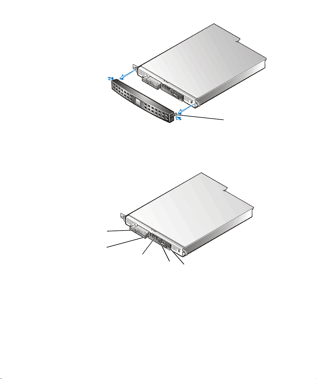
tabs (2)
Figure 1-1. Removing the Optional Front Bezel
Front-Panel Features
Figure 1-2 shows the main features on the system front panel.
diskette
drive
CD-ROM
drive
system indicators (5)
serial port 2
Figure 1-2. Front-Panel Features
system switches (3)
support.dell.com
Introduction 1-3
Page 12
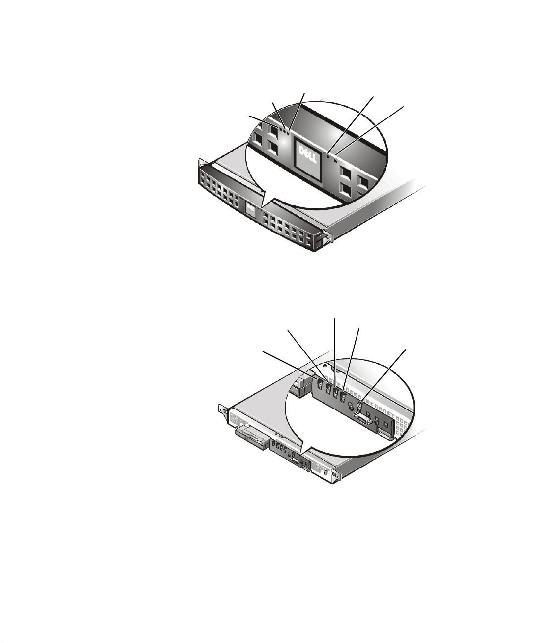
System Indicators
While troubleshooting your system, you may need to check the status of the indicators on the system’s front panel, shown in Figure 1-3 and Figure 1-4.
hard-disk drive activity indicator
system fault indicator
power indicator
Figure 1-3. Front-Panel Indicators
hard-disk drive activity indicator
system fault indicator
power indicator
LAN 1 activity/link indicator
LAN 2 activity/link
indicator
LAN 1 activity/link indicator
LAN 2 activity/link
indicator
1-4 User’sGuide
Figure 1-4. Front-Panel Indicators (Bezel Removed)
Page 13
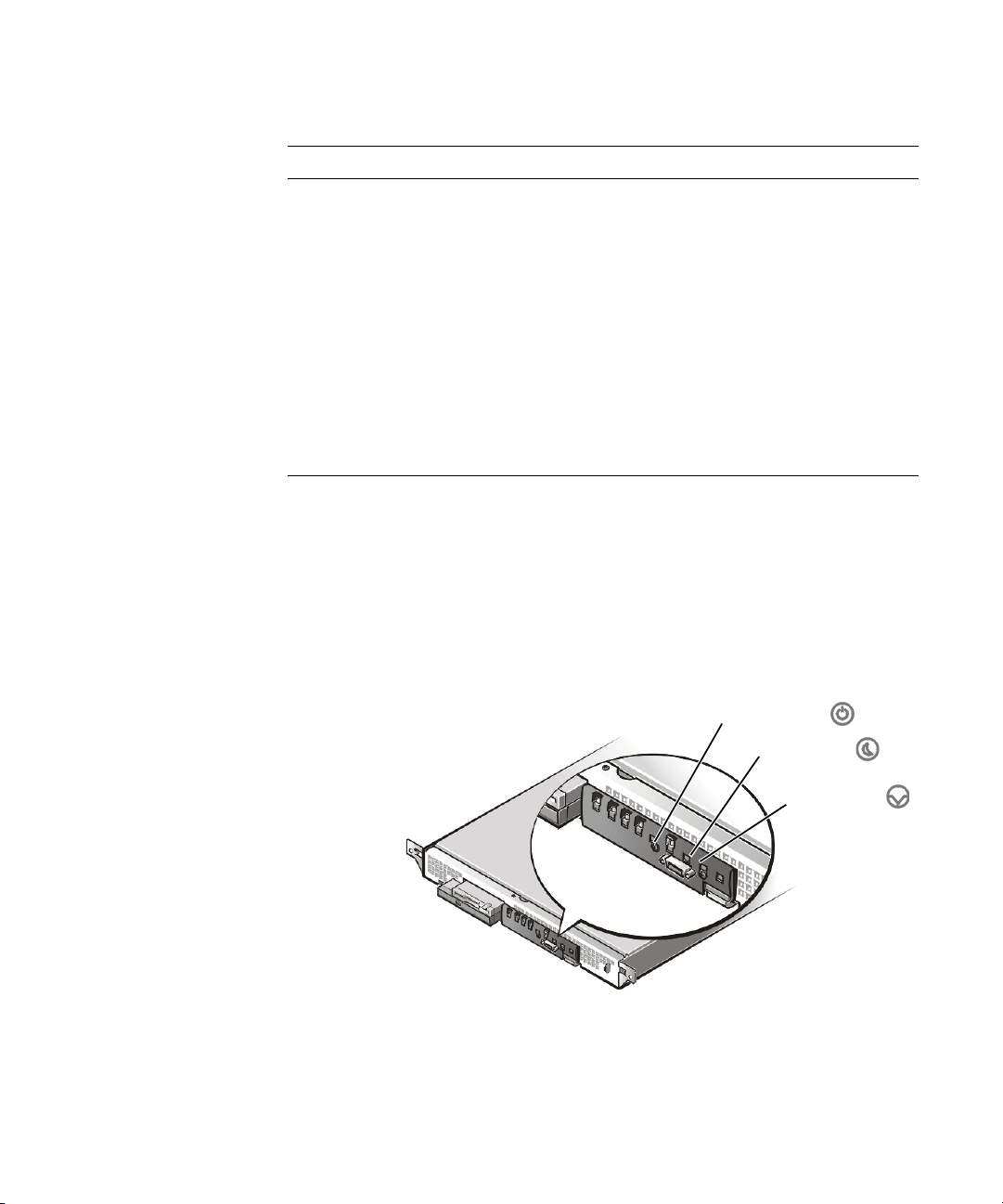
Table 1-1 describes the appearance and function of the front-panel indicators.
Table 1-1. Front-Panel Indicators
Indicator Color Function
Power Green Lights up when the system is connected to
an AC power source; blinks when the system is in sleep mode
System fault Amber Blinks during system startup, or when a
system fault is detected
Hard-disk drive activity Green Blinks when hard-disk drive activity occurs
LAN 1 activity/link Amber Lights up when the LAN 1 connector is
linked to an Ethernet port; blinks when
activity occurs on this channel
LAN 2 activity/link Amber Lights up when the LAN 2 connector is
linked to an Ethernet port; blinks when
activity occurs on this channel
System Switches
Figure 1-5 shows the location of the three switches on the system front panel. To activate a switch, press the corresponding icon on the front panel as shown in Figure 1-5.
NOTICE: To prevent accidental system lockup, system reset, or false error
messages, do not press areas of the front panel other than the three switch
locations shown in Figure 1-5. Reserved test switches are located in other
areas of the front panel.
support.dell.com
power switch
sleep switch
reset switch
Figure 1-5. Front-Panel Switches
Introduction 1-5
Page 14

Table 1-2 describes the function of the three front-panel switches.
Table 1-2. Front-Panel Switches
Switch Function
Power switch Turns power to the system board on or off.
NOTE: To turn system power off, press and
hold this switch for at least 4 seconds.
Sleep switch Places the system in sleep mode.
Reset switch Reboots the system. If the system locks up
and you cannot shut down the system
using the operating system,press the reset
switch.
Connecting External Devices
You can connect various external devices, such as a mouse or network connection, to
the input/output (I/O) ports and connectors on the system’s back panel. Figure 1-6
shows the back-panel connections on your system.
AC power receptacle
1-6 User’sGuide
keyboard and mouse
connectors (2)
USB connectors 0 (top) and 1
LAN connectors 2 (top) and 1
serial port 1
video connector
Figure 1-6. Back-Panel Connections
Page 15

The system basic input/output system (BIOS) detects the presence of external
devices when you boot or rebootyour system. When you connect external devices to
your system, follow these guidelines:
• Check the documentation that accompanied the device for specific installation
and configuration instructions.
• Always attach external devices while your system is turned off. Turn on any exter-
nal devices before turning on the system unless the documentation for the
device specifies otherwise. (If the system does not seem to recognize the
device, try turning on the system before turning on the device.)
Power Protection Devices
A number of devices are available that protect your system against power problems
such as power surges, transients, and power failures. The following subsections
describe some of these devices.
Surge Protectors
Surge protectors are available in a variety of types and usually provide a level of protection commensurate with the cost of the device. Surge protectors prevent voltage
spikes, such as those caused during an electrical storm, from entering a system
through the electrical outlet. Surge protectors, however, do not offer protection
against brownouts, which occur when the voltage drops more than 20 percent below
the normal AC line voltage level.
support.dell.com
Line Conditioners
Line conditioners go beyond the overvoltage protection of surge protectors. Line conditioners keep a system's AC power source voltage at a fairly constant level and,
therefore, can handle brownouts. Because of this added protection, line conditioners
cost more than surge protectors—up to several hundred dollars. However, these
devices cannot protect against a complete loss of power.
Uninterruptible Power Supplies
Uninterruptible power supply (UPS) systems offer the most complete protection
againstvariations in powerbecause they usebattery power tokeep thesystem running
when AC power is lost. The battery is charged by the AC power while it is available, so
once AC power islost, thebattery canprovide powerto thesystemfor a limited amount
of time—from 15 minutes to an hour or so—depending on the UPS system.
UPS systems range in price from a few hundred dollars to several thousand dollars,
with the more expensive units allowing you to run larger systems for a longer period
of time when AC power is lost. UPS systems that provide only 5 minutes of battery
power let you conduct an orderly shutdown of the system, but are not intended to
provide continued operation. Surge protectors should be used with all UPS systems,
and the UPS system should be Underwriters Laboratories (UL) safety-approved.
Introduction 1-7
Page 16

Getting Help
If at any time you do not understand a procedure described in this guide, or if your
system does not perform as expected, Dell provides a number of tools to help you.
Formoreinformationonthesehelptools,see“Getting Help” in your
Troubleshooting Guide.
Installation and
Safety, Regulatory, and Warranty
Information
For safety, regulatory, and warranty information for your system, see the
Information
document included with your system.
System
1-8 User’sGuide
Page 17

CHAPTER 2
Using the Dell OpenManage
Server Assistant CD
The
Dell OpenManage Server Assistant
other items that can help you configure your system to best meet your needs. This
chapter describes how to use the
Starting the Dell OpenManage Server
Assistant CD
The Dell OpenManage Server Assistant application program has two modes of operation: a
setup mode
and viewing information, and a
mation. Documentation is available on the
In both setup mode and service mode, the Dell OpenManage Server Assistant main
screen gives youthe option to choose one ofthe supported languages as thelanguage
for the screen text. You can choose a language at any time from the main screen.
for setting up and configuring your system, creating diskettes,
service mode
CD contains utilities, diagnostics, drivers, and
Dell OpenManage Server Assistant
for creating diskettes and viewing infor-
Dell Online Documentation
CD.
CD.
support.dell.com
Setup Mode
To set up your system, as well as to access the utilities, drivers, and other items available on the
Server Assistant
Dell OpenManage Server Assistant main page appears.
If the CD does not boot, verify that the Boot Sequence is set to CD-ROM device in
the System Setup program.
Dell OpenManage Server Assistant
CD into your CD-ROM drive, and turn on or reboot the system. The
CD, insert the
Dell OpenManage
Service Mode
You can create system diskettes and view information on any system that has
Microsoft Internet Explorer 4.0 (or later). When you insert the CD in a system that
uses the Microsoft Windows NT or Windows 2000 Server operating system, the system automatically starts the browser software and displays the
Dell OpenManage Server Assistant main page.
Using the Dell OpenManage Server Assistant CD 2-1
Page 18

Navigating the CD
The
Dell OpenManage Server Assistant
Navigating the CD is accomplished by clicking the mouse on the various icons and
text hyperlinks.
Click the Back icon to return to the previous screen. Click the Exit icon to exit the
program. Exiting the program causes the system to reboot to the standard operating
system boot partition.
CD utilizes a standard Web browser interface.
Setting Up Your System
If you purchase a system that does not have an operating system preinstalled by Dell,
or if you reinstall an operating system at a later date, you should use the Server
Setup option to configure your system or install your operating system.
Server Setup Mode
Dell recommends using the Server Setup program for most situations including installing and reinstalling an operating system. The
guidesyou throughtheoperating system setupand configurationprocess. The program
prompts you to select the operating system used on the drive and leads you through
a step-by-step process to install the operating system.
To start the Server Setup program, perform the following steps:
1. C l i ck t h e SETUP icon at the top of the screen.
Dell OpenManage Server Assistant
CD
2-2 User’s Guide
2. Click Server Setup.
After you start the Server Setup program, follow the directions on the screen to complete the installation and configuration process. The Server Setup program takes you
through the following tasks:
• Configuring your redundant array of independent disks (RAID) controller (if
applicable)
• Entering operating system and hard-disk drive information
• Entering operating system configuration
• Installing an operating system
Running System Diagnostics
To run the system diagnostics you must create diagnostics diskettes from the
Dell OpenManage Server Assistant
nostic Diskettes.”
The system hardware diagnostics are described in “Running the Dell Diagnostics” in
your
Installation and Troubleshooting Guide
CD. See the following subsection, “Creating Diag-
.
Page 19

Creating Diagnostic Diskettes
To create diagnostic diskettes from the
Create Diskettes from the Dell OpenManage Server Assistant menu and then continue down the menu hierarchy by selecting the following categories:
PowerEdge 350, Diskette Set, System Utilities, Server Diagnostics.Createfive
Server Diagnostics diskettes. To run the diagnostics, reboot your system with the first
diskette you made.
Dell OpenManage Server Assistant
CD, select
Creating an Asset Tag
Using Dell OpenManage IT Assistant, you can enter an asset tag number for your system. An asset tag number can have up to ten characters and any combination of
characters, excluding spaces.
To create an asset tag number, perform the following steps:
1. F r o m t h e
Assistant in Read/Write mode.
2. From the main Dell OpenManage IT Assistant window, select Servers.
3. From the new window, select the particular server for which you wish to create
the asset tag.
4. Select the Status tab and click the Asset Tag Field.
5. Log in to Dell OpenManage IT Assistant. You must have administrative rights to
do this.
6. In the Edit Attribute dialog box,type the asset tag number you want to assign to
the system and click OK.
Dell OpenManage Server Assistant
CD, select Dell OpenManage IT
support.dell.com
Using the Dell OpenManage Server Assistant CD 2-3
Page 20

2-4 User’sGuide
Page 21

CHAPTER 3
Using the System Setup Program
Each time you turn on your system, the system compares the configuration of the
hardware installed in the system to the hardware listed in the system configuration
information stored in nonvolatile random-access memory (NVRAM) on the system
board. If the system detects a discrepancy, it generates error messages that identify
the incorrect configuration settings. The system then prompts you to enter the System Setup program to correct the setting.
You can use the System Setup program as follows:
• To change the system configuration information after you add, change, or remove
any hardware in your system
• To set or change user-selectable options—for example, the time or date on your
system
Afteryousetupyoursystem,runtheSystemSetupprogramtofamiliarizeyourself
with your system configuration information and optional settings. Dell recommends
that you print the System Setup screens (by pressing <Print Screen>) or record the
information for future reference.
support.dell.com
Before you use the System Setup program, you need to know the kind of diskette
drive(s) and hard-disk drive(s) installed in your system.If you are unsure of any of this
information, see the Manufacturing Test Report that was shipped with your system.
You can access the Manufacturing Test Report from the Dell Accessories folder.
NOTE: The PowerEdge 350 system is a “headless” system that operates without
keyboard, monitor, or mouse. You must connect the keyboard and monitor to perform
the procedures in this chapter.
Entering the System Setup Program
Enter the System Setup program as follows:
1. Turn on your system.
If your system is already on, shut it down and then restart it.
2. Press <F2> immediately after you see the following message:
F2 = Setup
UsingtheSystemSetupProgram 3-1
Page 22

If you wait too long and your operating system begins to load into memory, let
the system complete the load operation, and then shut down the system and try
again.
NOTE: To ensure an orderly system shutdown, consult the documentation that
accompanied your operating system.
You can also enter the System Setup program by responding to certain error messages. See “Responding to Error Messages” in the following section.
Responding to Error Messages
If an error message appears on your monitor screen while the system is booting,
make a note of the message. Then, before entering the System Setup program, see
“POST Beep Codes” and “System Messages” in your
Troubleshooting Guide
ing any errors. (An exception to this routine: It is normal to receive an error message
the first time you boot your system after installing a memory upgrade. In that situation, do not refer to “POST Beep Codes” and “System Messages.” Instead, follow
the instructions for performing a memory upgrade in “Memory Modules” in your
Installation and Troubleshooting Guide
If you are given an option of pressing either <F1> to continue or <F2> to run the System Setup program, press <F2>.
for an explanation of the message and suggestions for correct-
.)
Installation and
Using the System Setup Navigation Keys
Table 3-1 lists the keys that you use to view, move around in, or change information on
the System Setup screens and to exit the program.
3-2 User’sGuide
NOTE: For help using the System Setup program, press <F1>.
Table 3-1. System Setup Navigation Keys
Keys Action
Activates submenus, displays a list, or selects a
subfield depending on the type of action being
performed.
Selects a field within a configurable field.
Selects the previous or next value in a list, or
the previous or next feature in a menu item’s
option list.
Page 23

Table 3-1. System Setup Navigation Keys (continued)
Keys Action
Moves between major menu pages.
Backs you out of any field. This key also undoes
any action completed by pressing <Enter>,
branches back to the parent menu if pressed
while editing any field or selecting features in a
menu, branches back to the parent menu when
pressed in any submenu, or displays the exit
confirmation window and asks whether
changes can be discarded when pressed in any
major menu.
Loads the default values for all fields. A menu
appears asking you to confirm. Select Ye s to
load the default options; select No to remain in
theSystemSetupprogram.
Saves the current field values and exits System
Setup. A menu appears asking you to confirm.
Select Ye s to save and exit; select No to remain
in the System Setup program.
support.dell.com
UsingtheSystemSetupProgram 3-3
Page 24

System Setup Menus and Options
The following subsections outline the menus and their associated options on the System Setup menu bar.
Main Menu
When the System Setup program runs, the BIOS SETUP UTILITY main program
screen appears (see Figure 3-1).
3-4 User’sGuide
Figure 3-1. BIOS Setup Utility Screen
Notice that along the top of the screen is the BIOS SETUP UTILITY menu bar con-
taining the following BIOS SETUP UTILITY menu options:
• Main
• Advanced
• Security
• Boot
• System Management
• Exit
These menu option items are explained in more detail in the following subsections.
The following options or information fields appear on the Main BIOS SETUP UTILITY
screen:
• BIOS Version — Displays the basic input/output system (BIOS) version.
• Processor Type — Displays the microprocessor type. This option has no user-
selectable settings.
Page 25

• Processor Speed — Displays the microprocessor speed in megahertz (MHz). This
option has no user-selectable settings.
• Processor Serial Number — Enables or disables (the default option) the microproces-
sor serial number (PSN).
NOTE: This option is only available on systems with a Pentium III processor.
• Cache RAM — Displays the cache random access memory (RAM) size in kilobytes (KB).
This option has no user-selectable settings.
• To t a l M e m o r y — Displays the amount of system memory. This option has no user-
selectable settings.
• Memory Bank 0, Memory Bank 1, Memory Bank 2, Memory Bank 3 — Displays the
memory type for each memory back. If no memory is present, Not Installed dis-
plays. This option has no user-selectable settings.
• Language — Selects the language used by the systems BIOS. The options are:
— English (the default option)
— French
— German
— Italian
— Spanish
• Memory Configuration — Allows you to turn error reporting on or off.
NOTE: This option is only available on systems with system and memory that support
error correction code (ECC).
support.dell.com
• System Time — Resetsthetimeonthesystem'sinternalclock.
• System Date — Resets the date on the system's internal calendar.
NOTE: You can use the plus and minus keys to set the system time and date. Use the keys
on the numeric keypad only; it does not matter if NumLock is on or off.
UsingtheSystemSetupProgram 3-5
Page 26

Advanced Menu
Selecting the Advanced option on the menu bar allows you to configure the following
advanced system features:
• Boot Configuration — Configures the following functions on your system’snext
reboot:
— Plug & Play O/S — Specifies if a Plug and Play operating system is being
used. The default, No, configures all the devices in the system. Ye s allows
the system to configure Plug and Play devices not required for boot (assuming your system has a Plug and Play operating system).
— Reset Config Data — Clears the peripheral component interconnect/Plug
and Play (PCI/Plug and Play) configuration (stored in flash memory) on the
next boot.
— NumLock — Selects whether the <NumLock> key is off or on at system
power on.
• Peripheral Configuration — Configures the following peripheral ports and
devices.
— Serial Port A — Enables (the default) or disables your system’s serial port 1.
— Serial Port B — Enables (the default) or disables serial port 2.
— Legacy USB Support — Enables or disables (the default) support for your
system’s legacy USB.
• IDE Configuration — Configures the following IDE devices:
— IDE Controller — Disabled disables your system’s integrated IDE controller.
Primary enables only your system’s primary IDE controller. Secondary
enables your system’s secondary IDE controller. Both (the default) enables
both of your system’s IDE controllers.
— Hard-Disk Predelay — Selects your system’s hard-disk drive predelay:
3 seconds, 6 seconds, 9 seconds, 12 seconds, 15 seconds, 21 seconds,
or 30 seconds. This option also configures your system’sprimaryandsecondary IDE devices either as the name of the drive found, or as Not
Enabled.
— Primary IDE Master — Displays the name of your system’s installed device,
or displays Not Installed. If an IDE device is detected, you can configure the
following options: Ty p e (Auto is the default), LBA Mode Control (Enabled is
the default), Multi-Sector Transfers (16 sectors is the default), PIO Mode
(Auto is the default), Ultra MDA (Disabled is the default).
— Primary IDE Slave — Displays the name of your system’s installed device,
or displays Not Installed. If an IDE device is detected, you can configure the
following options: Ty p e (Auto is the default), LBA Mode Control (Enabled is
the default), Multi-Sector Transfers (16 sectors is the default), PIO Mode
(Auto is the default), Ultra MDA (Disabled is the default).
3-6 User’sGuide
Page 27

— Secondary IDE Master — Displays the name of your system’s installed
device, or displays Not Installed. If an IDE device is detected, you can configure the following options: Ty p e (Auto is the default), LBA Mode Control
(Enabled is the default), Multi-Sector Transfers (16 sectors is the default),
PIO Mode (Auto is the default), Ultra MDA (Disabled is the default).
— Secondary IDE Slave — Displays the name of your system’s installed
device, or displays Not Installed. If an IDE device is detected, you can configure the following options: Ty p e (Auto is the default), LBA Mode Control
(Enabled is the default), Multi-Sector Transfers (16 sectors is the default),
PIO Mode (Auto is the default), Ultra MDA (Disabled is the default).
• Diskette Configuration — Configures the following diskette drive settings:
— Diskette Controller — Enables (the default) or disables the integrated dis-
kette con tro ller.
— Floppy A — Enables (the default) or disables the diskette drive and specifies
its size: 360 KB 5.25”, 1.2 MB 5.25”, 720 KB 3.5”, 1.44/1.25 MB 3.5”,(the
default), or 2.88 MB 3.5”.
— Diskette Write Protect — Enables or disables (the default) write-protect for
thediskettedrive.
• Event Log Configuration — Configures the following event log options:
— Event Log — Displays whether or not space is available in your system’s
event log. This option has no user configurable settings.
— Event Log Validity — Displays whether or not the contents of your sys-
tem’s event log are valid. This option has no user configurable settings.
support.dell.com
— Clear All Event Logs — Clears your system’s event log after rebooting. No
is the default option.
— Event Logging — Enables (the default) or disables event logging.
— ECC Event Logging — Enables (the default) or disables ECC event logging.
Security Menu
Selecting the Security option on the menu bar allows you to set the following password and security features:
• User Password Is — Displays whether or not your system has a user password
installed (entered). This option has no user configurable settings.
• Supervisor Password Is — Displays whether or not your system has a supervi-
sor password installed (entered). This option has no user configurable settings.
• Set Supervisor Password — Specifies a supervisor password that can be up to
seven alphanumeric characters long. The default option is no supervisor password installed.
• SetUserPassword— Specifies a user password that can be up to seven alpha
numeric characters long. The default option is no supervisor password installed.
UsingtheSystemSetupProgram 3-7
Page 28

• Clear User Password — Clears your system’s installed user password. This
option has no user configurable settings.
NOTE: This feature is displayed only after the supervisor password is set.
• User Access Level — Limited allows the user to only change limited fields, such
as Date and Time. No Access prevents user access to the Setup Utility. View
Only allows user access to the Setup Utility but no fields can be changed. Full
allows the user to change any fields. Only the Supervisor password can set the
user access levels.
Boot Menu
Selecting the Boot Menuoption on the menu bar allows you to set the following boot
features and the boot sequence:
• Quiet Boot — Enables or disables (the default) displaying normal power-on self-
test (POST) messages.
• Quick Boot — Enables or disables (the default) your system’s quick boot capabil-
ity. This capability allows your system to skip certain tests while rebooting which
decreases the time needed to boot your system.
• After Power Failure — Specifies the mode of operation when power is lost:
Stays Off keeps your system off after power is restored, Power On boots the
system after power is restored, Last State (the default) restores the system to
the same state it was in before the power failed.
NOTE: To enable to BIOS to correctly set this feature, your system must be shut
down using the power switch.
3-8 User’sGuide
• On Modem Ring — Determines whether or not your system will Stay Off (the
default) or Power On when its power is off and the modem is ringing.
• On LAN — Determines whether or not your system will Stay Off or Power On
(the default) when a local area network (LAN) wake up event occurs.
• On PME — Determines whether or not your system will Stay Off (the default) or
Power On when its PCI Power Management Enabled wake up event occurs.
• IDE Drive Configuration — Configures your system’s peripheral devices. See
the following configurable options for other IDE devices which are similar to the
Primary Master IDE options:
— Primary Master IDE — Specifies the Primary Master IDE drive configura-
tion: 1st IDE (the default), 2nd IDE, 3rd IDE,or4th IDE.
— Primary Slave IDE — Specifies the Primary Slave IDE drive configuration:
1st IDE, 2nd IDE (the default), 3rd IDE,or4th IDE.
— Secondary Master IDE — Specifies the Secondary Master IDE drive con-
figuration: 1st IDE, 2nd IDE, 3rd IDE (the default), or 4th IDE.
— Secondary Slave IDE — Specifies the Secondary Slave IDE drive configu-
ration: 1st IDE, 2nd IDE, 3rd IDE,or4th IDE (the default).
• 1st to 8th Boot — Configures your system’s boot sequence from its available
devices: Floppy (the default), IDE-HDD, ATAPI CD-ROM,andIDE-HDD.
Page 29

System Management Menu
Selecting the System Management menu option allows you to set the following
server management features:
• Serial Console Redirection — Enables or disables (the default) your system’s
serial console redirection.
• Baud Rate — Sets your system’s baud rate: 9600, 19.2 KB (the default), 38.4 KB,
or 115 K B.
• Flow Control — Enables or disables one of the following flow controls: No Flow
Control, CTS/RTS (the default), XON/XOFF,orCTS/RTS+CD.
Exit Menu
Selecting the Exit menu option allows you to exit the System Setup program while
saving, discarding, or loading default settings:
• Exit Saving Changes — Exits your system’s setup and saves changes. This
option has no user-configurable settings.
• Exit Discarding Changes — Exits your system’s setup and discard changes. This
option has no user-configurable settings.
• Load Setup Defaults — Loads your system’s setup default settings. This option
has no user-configurable settings.
• Load Custom Defaults — Loads your system’s custom settings. This option has
no user-configurable settings.
• Save Custom Defaults — Saves your system’s custom settings. This option has
no user-configurable settings.
• Discard Changes — Discards your system’s changes. This option has no user-
configurable settings.
support.dell.com
Using the System Password Features
NOTICE: The password features provide a basic level of security for the
data on your system. However, they are not foolproof. If your data requires
more security, it is your responsibility to obtain and use additional forms of
protection, such as data encryption programs.
The System Setup program allows you to install supervisor and user passwords. A
supervisor password is used to access the System Setup program while a user password is used to access the system, such as when logging in.
Your Dell system is shipped to you without the supervisor password feature installed.
If system security is a concern, you should operate your system only with supervisor
password protection.
You can assign a supervisor password whenever you use the System Setup program.
After a supervisor password is assigned, only those who know the password have full
use of the System Setup program.
UsingtheSystemSetupProgram 3-9
Page 30

When the Set Supervisor Password option is Installed, the system then prompts
you for the supervisor password (only when going into system setup) just after the
system boots.
To change an existing supervisor password, you must know the supervisor password
(see the section “Deleting or Changing an Existing Supervisor Password” found later
in this chapter). If you assign and later forget a supervisor password, you need to be
able to remove the system cover to change a jumper setting that disables the supervisor password feature (see the section “Deleting a Forgotten Password” found later in
this chapter). Note that this procedure erases the user password at the same time.
NOTICE: If you leave your system running and unattended without having
a supervisor password assigned, or if you leave your system unlocked so
that someone can disable the password by changing a jumper setting, anyone can access the data stored on your hard-disk drive.
Assigning a Supervisor Password (System Setup Only)
Before you can assign a supervisor password, you must enter the System Setup program and select the Set Supervisor Password option.
NOTE: The supervisor password controls the user password access to the system
setup. See “Security Menu” earlier in this chapter for a description of the levels of
user password access.
When a supervisor password is assigned, the setting shown for the Set Supervisor
Password option is Installed.
3-10 User’sGuide
When no supervisor password is assigned and the password jumper on the system
board is in the uninstalled position (its default), the setting shown for the Set Super-
visor Password option is Not Installed. Only when this option is set to Not Installed
can you assign a supervisor password, using the following procedure:
1. Enter the System Setup program by pressing <F2>.
2. Select the Security screen.
3. Verify that the Supervisor Password Is option is set to Not Installed.
4. Select the Set Supervisor Password option and press <Enter>.
The system prompts you to Enter Supervisor Password.
5. Type your supervisor password.
You can use up to seven characters in your password.
As you press each character key (or the spacebar key for a blank space), an asterisk (*) placeholder appears in the field.
The password assignment operation recognizes keys by their location on the keyboard; it is case sensitive. This means that the software distinguishes between
lowercase and uppercase characters. For example, if you have an
word, the system does not recognize either
Morm
as correct; your system will
M
in your pass-
Page 31

only acceptM. Certain keys and key combinations are not valid. If you enter one
of these keys or combinations, the system does not accept them. To erase a
character when entering your password, press <Backspace> or the left-arrow
key.
NOTE: To escape from the field without assigning a supervisor password, press
the <Esc> key at any time before completing step 5.
6. Press <Enter>.
The system prompts you to Confirm New Password, followed by another
empty seven-character field in square brackets.
7. To confirm your new password, type it a second time and press <Enter>.
The system tells you the Password Successfully Installed.
The password setting changes to Installed. Your supervisor password is now set;
you can exit the System Setup program and begin using your system. Note,
however, that password protection does not take effect until you reboot the system by turning the system off and then on again.
Using Your Supervisor Password to Secure Your System
Setup
If the Supervisor Password Is option is set to Installed, the following prompt
appears:
Enter CURRENT Password
After you type the correct supervisor password and press <Enter>, you can log on to
the system as you normally would.
If a wrong or incomplete supervisor password is entered, the following message
appears:
Enter CURRENT Password
If an incorrect or incomplete supervisor password is entered again, the same message appears.
The third and subsequent times an incorrect or incomplete supervisor password is
entered, the system displays the following message:
Invalid Password-System Halted
To reboot the system and either set a new password, press <Ctrl><Alt><Del> or the
reset button on the system unit.
The number of unsuccessful attempts made to enter the correct supervisor password
can alert you to an unauthorized person attempting to use your system.
Even after your system is turned off and on, the previous message is displayed each
time an incorrect or incomplete supervisor password is entered.
support.dell.com
UsingtheSystemSetupProgram 3-11
Page 32

NOTE: The supervisor password only applies to the System Setup program. A user
password should be installed to completely secure your system. See “Assigning a
User Password” found later in this chapter.
Deleting or Changing an Existing Supervisor Password
To delete or change an existing supervisor password, perform the following steps:
1. Enter the System Setup program by pressing <F2>.
2. Select the Security screen field to verify that the Supervisor Password Is option
is set to Installed.
3. Select the Set Supervisor Password option and press <Enter>.
The system prompts you to Enter Current Password.
4. Type your current supervisor password and press <Enter>
The system prompts you to Enter Supervisor Password.
NOTE: If you want to delete the password and not enter a new password, press
<Enter> without typing in a new password, leaving the Enter Supervisor Pass-
word field blank.
5. To assign a new password, follow the procedure from step 4 on in “Assigning a
Supervisor Password (System Setup Only)” found earlier in this chapter.
3-12 User’sGuide
Using the User Password Feature
Your Dell system is shipped to you without the user password feature installed. If system security is a concern, you should operate your system with user password
protection.
You can assign a user password whenever you use the System Setup program. After
a user password is assigned, only those who know the password have access to the
System Setup program.
To change an existing user password, you must know the user password (see the section “Deleting or Changing an Existing User Password” found later in this chapter). If
you assign and later forgeta userpassword, you need to beable to remove the system
cover to change a jumper setting that disables the user password feature. See “Deleting a Forgotten Password” found later in this chapter. Note that this procedure erases
the supervisor password at the same time.
NOTICE: If you leave your system running and unattended without having
a user password assigned, or if you leave your system unlocked so that
someone can disable the password by changing a jumper setting, anyone
can access the data stored on your hard-disk drive.
Page 33

Assigning a User Password
Before you can assign a user password, you must enter the System Setup program
and select the SetUserPasswordoption.
To assign a user password, perform the following steps:
1. Enter the System Setup program by pressing <F2>.
2. Select the Security screen.
3. Select the SetUserPasswordoption and press <Enter>.
The system prompts you to Enter User Password.
4. Type your user password.
You can use up to seven characters in your password.
As you press each character key (or the spacebar key for a blank space), an asterisk (*) placeholder appears in the field.
The password assignment operation recognizes keys by their location on the keyboard; it is case sensitive. This means that the software distinguishes between
lowercase and uppercase characters. For example, if you have an
word, the system does not recognize either
only accept
of these keys or combinations, the system does not accept them. To erase a
character when entering your password, press <Backspace> or the left-arrow
key.
M
. Certain keys and key combinations are not valid. If you enter one
Morm
as correct; your system will
M
in your pass-
support.dell.com
NOTE: To escape from the field without assigning a user password, press the
<Esc> key at any time prior to completing step 4.
5. Press <Enter>.
The system prompts you to Confirm New Password, followed by another
empty seven-character field in square brackets.
6. To confirm your password, type it a second time and press <Enter>.
The system tells you that the Password Successfully Installed.
The password setting changes to Installed. Your supervisor password is now set;
you can exit the System Setup program and begin using your system. A change
to the Set User Password option becomes effective immediately (rebooting the
system is not required).
NOTES: The user password can be the same as the supervisor password.
If the two passwords are different, the user password can be used as an alternate
supervisor password. However, the supervisor password cannot be used in place of
the user password.
UsingtheSystemSetupProgram 3-13
Page 34

Operating With a User Password Installed
If Set User Password is set to Installed, you must enter the correct user password
before you can modify the majority of the System Setup options. When you start the
System Setup program, the program prompts you to type the password.
If you do not enter the correct password in three tries, the system displays the following message:
Invalid Password-System Halted
Deleting or Changing an Existing User Password
To delete or change an existing user password, perform the following steps:
1. Enter the System Setup program by pressing <F2>.
2. Select the Security screen field to verify that the User Password Is option is set
to Installed.
3. Select the SetUserPasswordoption and press <Enter>.
The system prompts you to Enter Current Password.
4. Type your current user password and press <Enter>
The system prompts you to Enter User Password.
NOTE: If you want to delete the password and not enter a new password, press
<Enter> without typing in a new password, leaving the Enter User Password
field blank.
3-14 User’sGuide
5. To assign a new password, follow the procedure from step 4 in “Assigning a
User Password” found earlier in this chapter.
Deleting a Forgotten Password
If you forget your supervisor or user password, you cannot operate your system or
change settings in the System Setup program until someone having a supervisor
password clears and installs a new user password.
If you forgot your supervisor or user password, you cannot operate your system or
change settings in the System Setup program until a trained service technician opens
the system chassis, changes the password jumper setting to disable the passwords,
and erases the existing passwords. This procedure is described in “Disabling Forgotten Passwords” in the
Installation and Troubleshooting Guide
.
Page 35

APPENDIX A
Technical Specifications
Table A-1. Technical Specifications
Microprocessor
Microprocessor type Intel Celeron microprocessor with a minimum
internal operating frequency of 600 MHz
or
Intel Pentium III microprocessor with an internal
operating frequency of 750 MHz
L2 cache 128 KB, internal to microprocessor for the Cele-
ron processor; 256 KB for the Pentium III
microprocessor
Math coprocessor internal to microprocessor
Expansion Bus
Bus type PCI bus
support.dell.com
Expansion slots one full-length PCI, one low-profile PCI
(occupied by video controller)
Memory
DIMM sockets 72-bit wide, 168-pin sockets
DIMM capacities 128-, or 256-MB registered SDRAM DIMMs;
must be rated for 100-MHz operation
Minimum RAM 128 MB
Maximum RAM 1 GB
NOTE: For the full name of an abbreviation or acronym used in this table, see the “Glossary.”
Technical Specifications A-1
Page 36

Table A-1. Technical Specifications (continued)
Drives
Diskette drive 3.5-inch, 1.44-MB diskette drive included with
standard system
Hard-disk drives two 1-inch form-factor ATA-100 IDE hard-disk
drives
CD-ROM drive IDE
Ports
Externally accessible:
Serial two 9-pin connectors
USB two 4-pin connectors
RJ45 two RJ45 connectors for connection to two inte-
grated Intel 82559 10/100 Ethernet controllers
Video 15-pin connector on expansion card
PS/2-style keyboard 6-pin mini-DIN
PS/2-compatible mouse 6-pin mini-DIN
Video
Video type PCI video controller; VGA connector
A-2 User’sGuide
Video memory (standard) 8 MB SDRAM
1
Power
AC power supply:
Wattage 125 W
Voltage 100 to 120 V at 50 Hz/200 to 240 V at 60 Hz
System battery CR2032 3-V lithium coin cell
1
Under typical line conditions and over the entire system ambient operating range, the inrush
may reach 140A.
NOTE: For the full name of an abbreviation or acronym used in this table, see the “Glossary.”
Page 37

Table A-1. Technical Specifications (continued)
Physical
Height 4.3 cm (1.7 inches)
Width 42.5 cm (16.7 inches)
Depth 55 cm (22 inches)
Weight 10 kg (23 lb) maximum
Environmental (PE)
Temperature:
Operating 10° to 35°C(50° to 95°F)
Storage –40° to 65°C(–40° to 149°F)
Relative humidity:
Operating 8% to 80% (noncondensing) with a humidity
gradation of 10% per hour
Storage 5% to 95% (noncondensing)
Maximum vibration:
Operating 0.25 G (half-sine wave) at a sweep of 3 to 200 Hz
for 15 minutes
Storage 0.5 G at 3 to 200 Hz for 15 minutes
Maximum shock:
Operating six consecutively executed shock pulses in the
positive and negative x, y, and z axes (one pulse
on each side of the system) of 41 G for up to
2ms
Storage (non-operational) six consecutively executed shock pulses in the
positive and negative x, y, and z axes (one pulse
on each side of the system) of 71 G for 2 ms
Altitude:
Operating –16 to 3048 m (–50 to 10,000 ft)
Storage –16 to 10,600 m (–50 to 35,000 ft)
NOTE: For the full name of an abbreviation or acronym used in this table, see the “Glossary.”
support.dell.com
Technical Specifications A-3
Page 38

A-4 User’sGuide
Page 39

APPENDIX B
I/O Ports and Connectors
This section provides specific information about the input/output (I/O) ports and connectors on the back panel of the system.
I/O Ports and Connectors
The I/O ports and connectors on the back panel of the system are the gateways
through which the system communicates with external devices, such as a keyboard,
mouse, printer, and monitor. Figure B-1 identifies the I/O ports and connectors for
your system.
AC power receptacle
keyboard and mouse
connectors (2)
support.dell.com
USB connectors 0 (top) and 1
LAN connectors 2 (top) and 1
serial port 1
video connector
Figure B-1. I/O Ports and Connectors
I/O Ports and Connectors B-1
Page 40

Serial Ports
The two integrated serial ports on the front and back panels of the system use 9-pin
D-subminiature connectors. These ports support devices such as external modems,
printers, plotters, and mice that require serial data transmission (the transmission of
data one bit at a time over one line).
Most software uses the term COM (for communications) plus a number to designate
a serial port (for example, COM1 or COM2). Thedefault designations of your system's
integrated serial ports are COM1 and COM2.
Serial Port Connectors
If you reconfigure your hardware, you may need pin number and signal information for
the serial port connectors. Figure B-2 illustrates the pin numbers for the serial port
connectors and Table B-1 defines the pin assignments and interface signals for the
serial port connector.
Figure B-2. Pin Numbers for the Serial Port Connectors
B-2 User’s Guide
Table B-1. Serial Port Pin Assignments
Pin Signal I/O Definition
1 DCD I Data carrier detect
2 SIN I Serial input
3 SOUT O Serial output
4 DTR O Data terminal ready
5 GND N/A Signal ground
6 DSR I Data set ready
7 RTS O Request to send
8 CTS I Clear to send
9 RI I Ring indicator
Shell N/A N/A Chassis ground
Page 41

Keyboard and Mouse Connectors
The system uses a Personal System/2 (PS/2)-style keyboard and supports a
PS/2-compatible mouse. Cables from both devices attach to 6-pin, miniature
Deutsche Industrie Norm
Mouse driver software can givethe mouse priority with the microprocessor by issuing
IRQ12 whenever a new mouse movement is detected. The driver software also
passes along the mouse data to the application program that is in control.
Keyboard Connector
If you reconfigure your hardware, you may need pin number and signal information for
the keyboard connector. Figure B-3 illustrates the pin numbers for the keyboard
connector and Table B-2 defines the pin assignments and interface signals for the keyboard connector.
Figure B-3. Pin Numbers for the Keyboard Connector
.
(DIN) connectors on the back panel of your system.
support.dell.com
Table B-2. Keyboard Connector Pin Assignments
Pin Signal I/O Definition
1 KBDATA I/O Keyboard data
2 NC N/A No connection
3 GND N/A Signal ground
4 FVcc N/A Fused supply voltage
5 KBCLK I/O Keyboard clock
6 NC N/A No connection
Shell N/A N/A Chassis ground
Mouse Connector
If you reconfigure your hardware, you may need pin number and signal information for
the mouse connector. Figure B-4 illustrates the pin numbers for the mouse connector,
and Table B-3 defines the pin assignments and interface signals for the mouse
connector.
I/O Ports and Connectors B-3
Page 42

Figure B-4. Pin Numbers for the Mouse Connector
Table B-3. Mouse Connector Pin Assignments
Pin Signal I/O Definition
1 MSDATA I/O Mouse data
2 NC N/A No connection
3 GND N/A Signal ground
4 FVcc N/A Fused supply voltage
5 MSCLK I/O Mouse clock
6 NC N/A No connection
Shell N/A N/A Chassis ground
Video Connector
The system uses a 15-pin high-density D-subminiature connector on a video controller
for attaching a video graphics array (VGA)-compatible monitor to your system. The
video circuitry on the system board synchronizes the signals that drive the red, green,
andblueelectrongunsinthemonitor.
B-4 User’sGuide
If you reconfigure your hardware, you may need pin number and signal information for
the video connector. Figure B-5 illustrates the pin numbers for the video connector,
and Table B-4 defines the pin assignments and interface signals for the video
connector.
Figure B-5. Pin Numbers for the Video Connector
Page 43

Table B-4. Video Connector Pin Assignments
Pin Signal I/O Definition
1 RED O Red video
2 GREEN O Green video
3 BLUE O Blue video
4 NC N/A No connection
5–8, 10 GND N/A Signal ground
9 VCC N/A Vcc
11 NC N/A No connection
12 DDC data out O Monitor detect data
13 HSYNC O Horizontal synchronization
14 VSYNC O Vertical synchronization
15 DDC clock out O Monitor detect clock
Shell N/A N/A Chassis ground
USB Connectors
Your system contains two Universal Serial Bus (USB) connectors for attaching USBcompliant devices. USB devices are typically peripherals such as mice, printers,
keyboards, and system speakers.
NOTICE: Do not attach a USB device or a combination of USB devices that
draw a maximum current over 500 milliamperes (mA) per channel or +5
volts (V). Attaching devices that exceed this threshold may cause the USB
ports to shut down. See the documentation that accompanied the USB
devices for their maximum current ratings.
If you reconfigure your hardware, you may need pin number and signal information for
the USB connectors. Figure B-6 illustrates the USB connector and Table B-5 defines
the pin assignments and interface signals for the USB connector.
Figure B-6. Pin Numbers for the USB Connector
support.dell.com
I/O Ports and Connectors B-5
Page 44

Table B-5. USB Connector Pin Assignments
Pin Signal I/O Definition
1 Vcc N/A Supply voltage
2 DATA I Data in
3 +DATA O Data out
4 GND N/A Signal ground
Integrated Network Interface Controller
Connector
Your system has two integrated 10/100–megabit-per-second (Mbps) network interface
controllers (NICs). Each NIC provides all the functions of a separate network expansion card and supports both the 10BASE-T and 100BASE-TX Ethernet standards.
Each NIC includes a Wakeup On LAN feature that enables the system to be started by
a special local areanetwork (LAN) signal from a server management console. Wakeup
On LAN provides remote system setup, software downloading and installation, file
updates, and asset tracking after hours and on weekends when LAN traffic is typically
at a minimum.
Network Cable Requirements
Your system's RJ45 NIC connectors are designed for attaching an unshielded twisted
pair (UTP) Ethernet cable equipped with standard RJ45-compatible plugs. Press one
end of the UTP cable into the NIC connector until the plug snaps securely into place.
Connect the other end of the cable to an RJ45 jack wall plate or to an RJ45 port on a
UTP concentrator or hub, depending on your network configuration. Observe the following cabling restrictions for 10BASE-T and 100BASE-TX networks.
B-6 User’sGuide
Page 45

NOTICE: To avoid line interference, voice and data lines must be in separate sheaths.
• For 10BASE-T networks, use Category 3 or greater wiring and connectors.
• For 100BASE-TX networks, use Category 5 or greater wiring and connectors.
• The maximum cable run length (from a workstation to a concentrator) is 328 feet
(ft) (100 meters [m]).
• For 10BASE-T networks, the maximum number of daisy-chained concentrators
on one network segment is four.
support.dell.com
I/O Ports and Connectors B-7
Page 46

B-8 User’sGuide
Page 47

Glossary
The following list defines or identifies
technical terms, abbreviations, and acronyms used in Dell user documents.
A
Abbreviation for ampere(s).
AC
Abbreviation for alternating current.
adapter card
An expansion card that plugs into an
expansion-card connector on the system'ssystemboard.An adaptercard adds
some specialized function to the system
by providing an interface betweenthe expansion bus and a peripheral device.
Examples of adapter cards include network cards, sound boards, and SCSI
adapters.
application program
Software designed to help you performa
specific task, such as a spreadsheet or
wordprocessor.Applicationprogramsare
distinct from operating system and utility
software.
backup
A copy of a program or data file. As a
precaution, you should back up your system's hard-disk drive on a regular basis.
baud rate
Data transmission speed. For example,
modems aredesigned to transmit dataat
one or more specified baud rate(s)
throughthe COM(serial)port ofa system.
BBS
Abbreviation for bulletin board service. A
system that serves as a central location
for accessing data or relaying messages
by modem. For example, Dell's TechConnect BBS contains the latest version of
software such as video drivers and the
Dell Directory. If your system has a
modem, you can access the BBS and
download the most recent version of this
software.
beep code
A diagnostic system message inthe form
of a series of beeps from your system's
speaker. See your
Troubleshooting Guide
cussion of system beep codes.
BIOS
Acronym for basic input/output system.
Your system's BIOS contains programs
stored on a ROM chip. TheBIOS controls
the following functions:
Installation and
for acompletedis-
• Communications between the
microprocessor and peripheral
devices such as the keyboard and
the video adapter
• Miscellaneous functions, such as
system messages
bit
The smallest unit ofinformation interpreted by your system.
boot routine
When you start your system, it clears all
memory,initializesdevices, andloads the
operating system. Unless the operating
support.dell.com
Glossary 1
Page 48

system fails to respond, you can reboot
(also called warm boot) your system by
pressing <Ctrl><Alt><Del>; otherwise,
you mustperform acold boot bypressing
the reset button (if your system has one)
or by turning the system off andthen back
on.
bootable diskette
You canstart your system from adiskette
in drive A. To make a bootable diskette,
insertadisketteindriveA,typesys a:
at the command line prompt and then
press <Enter>. Use this bootable diskette
if yoursystem will not boot from the harddisk drive.
cm
Abbreviation for centimeter(s).
controller
A chip or expansion card that controls the
transfer of data between the microprocessor and a peripheral such as a
diskette drive or the keyboard.
conventional memory
The first 640 KB ofRAM. Unless they are
specially designed, MS-DOS programs
are limited to running in conventional
memory. See alsoEMM, expanded memory, extended memory, HMA, memory
manager, upper memory area, andXMM.
bus
A bus forms an information pathway between thecomponents of asystem. Your
system contains an expansion busthat allowsthe microprocessorto communicate
with controllers for all the various peripheral devices connected to the system.
Yoursystem alsocontainsan address bus
and a data bus for communications between the microprocessor and RAM.
byte
Eight contiguous bits of information; the
basic data unit used by your system.
C
Abbreviation for Celsius.
cache
To facilitate quicker data retrieval, a storage area for keeping a copy of data or
instructions. For example, your system's
BIOS may cache ROM code in faster
RAM. Or a disk-cache utility may reserve
RAM in which to store frequently accessed information from your system's disk
drives; when a program makes a request
toadiskdrivefordatathatisinthecache,
the disk-cache utilitycan retrieve the data
from RAMfaster thanfrom the disk drive.
CD-ROM
Abbreviation for compact disc read-only
memory. CD-ROM drives use optical
technology to read data from compact
discs. CDsare read-only storage devices;
you cannot write new data to a CD with
standard CD-ROM drives.
coprocessor
A coprocessor relieves the system's microprocessor of specific processing
tasks. A math coprocessor, for example,
handles numeric processing. A graphics
coprocessorhandles video rendering.The
IntelPentium microprocessorincludes an
integrated math coprocessor.
cpi
Abbreviation for characters per inch.
CPU
Abbreviation for central processing unit.
Seealsomicroprocessor.
DC
Abbreviation for direct current.
device driver
A device driver allows the operating system or a program to interface correctly
with a peripheral such as a printer or network card. Somedevice drivers—such as
network drivers—must be loaded from
the config.sys file (with a device= statement) or as memory-resident programs
(usually,from the autoexec.bat file). Oth-
ers—such as video drivers—must load
when you start the program for which
they were designed.
DHCP
Acronym for DynamicHost Configuration
Protocol.
2User’sGuide
Page 49

diagnostics
See diskette-based diagnostics.
DIMM
Acronym for dualin-line memory module.
DIN
Acronym for Deutsche Industrie Norm.
DIP
Acronymfor dualin-linepackage. Acircuit
board, such as a system board or expansion card, may contain DIP switches for
configuring the circuit board. DIP switches are always toggle switches, with an
ON position and an OFF position.
directory
Directories help keep related files organized in a hierarchical, "inverted tree"
structure.Each disk hasa "root" directory;
for example, a C:\> prompt normally indicates that you are at the root directory of
hard-disk drive C. Additional directories
that branch off of the root directory are
calledsubdirectories.Subdirectoriesmay
contain additional directories branching
off of them.
Diskette
Troubleshooting Guide
discussionabout how to use the diskettebased diagnostics.
display adapter
See video adapter.
DMA
Abbreviation fordirect memory access. A
DMA channel allows certain typesof data
transfer between RAM and a device to
bypass the microprocessor.
DRAC
Acronym for Dell OpenManage Remote
Assistant Card.
DRAM
Abbreviationfor dynamic random-access
memory. A system's RAM is usually
made up entirely of DRAM chips. Because DRAM chips cannot store an
electrical chargeindefinitely,your system
continually refreshes each DRAM chip in
the system.
drive-type number
Your system can recognize a number of
specifichard-diskdrives.Each isassigned
a drive-type number that is stored in
NVRAM. The hard-disk drive(s) specified
in your system's System Setup program
must match the actual drive(s) installed in
the system. The System Setup program
also allows you to specify physical parameters (cylinders, heads, write precomp,
landing zone, and capacity) for drives not
included in the table of drive types stored
in NVRAM.
. Refer to your
Installation and
for a complete
support.dell.com
diskette-based diagnostics
A comprehensive set of diagnostic tests
for your Dell system. To use the diskettebased diagnostics, you must boot your
system from the
Dell Diagnostics
ECC
Abbreviation for error checking and
correction.
EEPROM
Acronym for electrically erasable programmable read-only memory.
expansion bus
Your system contains an expansion bus
that allows the microprocessor to communicate with controllers for peripheral
devices, such as a network card or an internal modem.
Glossary 3
Page 50

expansion-card connector
A connector on the system's system
board for plugging in an expansion card.
external cache memory
A RAM cache using SRAM chips. Because SRAM chips operate at several
times the speed of DRAM chips, the
microprocessor can retrieve data and instructions faster from external cache
memory than from RAM.
controllerfor a peripheral.(Hard-diskdrive
controller subsystems include integrated
host adapter circuitry.) To add a SCSI expansion bus to your system, you must
install the appropriate host adapter.
Hz
Abbreviation for hertz.
IC
Abbreviation for integrated circuit.
F
Abbreviation for Fahrenheit.
flash memory
A type of EEPROM chip thatcan bereprogrammedfromautilityondiskettewhile
still installed in a system;most EEPROM
chips can only be rewritten with special
programming equipment.
format
To preparea hard-diskdrive ordiskettefor
storing files. An unconditional format deletes all data stored on the disk. The
formatcommandin MS-DOS5.0or higher
includes an option that allows you to unformat a disk ifyou have notyet used the
disk for file storage.
ft
Abbreviation for foot/feet.
g
Abbreviation for gram(s).
G
Abbreviation for gravities.
GB
Abbreviation for gigabyte(s). A gigabyte
equals 1024 megabytes or
1,073,741,824 bytes.
GUI
Acronym for graphical user interface.
h
Abbreviation for hexadecimal.
host adapter
A host adapter implements communication between the system's bus and the
I/O
Abbreviation for input/output. The keyboard and a printer, for example, are I/O
devices. Ingeneral, I/O activity can bedifferentiated from computational activity.
For example, when a program sends a
document to the printer, it is engaging in
I/O activity; when theprogram sorts a list
of terms, it is engaging in computational
activity.
ID
Abbreviation for identification.
IDE
Integrated drive electronics.
IP
Acronym for Internet Protocol.
IRQ
Abbreviation for interrupt request. A signal that data is about to be sent to or
received by a peripheral travels by anIRQ
line to themicroprocessor.Each peripheral connection must be assigned an IRQ
number. For example, the first serial port
in your system (COM1) is assigned to
IRQ4 by default. Two devices can share
thesame IRQassignment, but youcannot
operate both devices simultaneously.
K
Abbreviation for kilo-, indicating 1000.
KB
Abbreviation for kilobyte(s), 1024 bytes.
KB/sec
Abbreviation for kilobyte(s) per second.
4User’sGuide
Page 51

Kbit(s)
Abbreviation for kilobit(s), 1024 bits.
Kbps
Abbreviation for kilobit(s) per second.
key combination
A command requiring that you press multiple keys at thesame time.For example,
you can reboot your system by pressing
the <Ctrl><Alt><Del> key combination.
kg
Abbreviation for kilogram(s), 1000 grams.
kHz
Abbreviation for kilohertz, 1000 hertz.
LAN
Acronym for local area network. A LAN
system is usually confined to the same
buildingor afew nearby buildings, withall
equipment linked by wiring dedicated
specifically to the LAN.
lb
Abbreviation for pound(s).
LCD
Abbreviation for liquid crystal display. A
low-power display often used for notebooksystems. AnLCD consists ofa liquid
crystal solution between two sheets of
polarizing material. An electric current
causes each crystal to act like a shutter
that can open to allow light past or close
to block the light.
MB
Abbreviation for megabyte(s). The term
megabyte means 1,048,576 bytes; however, when referring to hard-disk drive
storage, the term is often rounded to
mean 1,000,000 bytes.
memory
A system can contain several different
forms of memory, such as RAM, ROM,
and video memory. Frequently, the word
memory is used as a synonym for RAM;
for example, an unqualified statement
such as"a system with 8 MB ofmemory"
refers to a system with 8 MB of RAM.
memory address
A specific location, usually expressed as
a hexadecimal number, in the system's
RAM.
MHz
Abbreviation for megahertz.
microprocessor
Because it is the primary computational
chip inside the system, it is customary to
refer to the microprocessor as "the
system's brain." The microprocessor contains an arithmetic processing unit and a
control unit. Software written for one microprocessor must usually be revised to
run on another microprocessor. CPU is a
synonym for microprocessor.
min
Abbreviation for minute(s).
support.dell.com
LED
Abbreviation for light-emitting diode. An
electronic device that lights up when a
current is passed through it.
LUN
Acronym for logical unit number.
m
Abbreviation for meter(s).
mA
Abbreviation for milliampere(s).
mAh
Abbreviation for milliampere-hour(s).
mm
Abbreviation for millimeter(s).
mouse
A pointing device that controls the
movement of the cursor on a screen.
Mouse-awaresoftwareallowsyouto
activate commands by clicking a mouse
buttonwhile pointing atobjects displayed
on the screen.
ms
Abbreviation for millisecond(s).
Glossary 5
Page 52

MS-DOS
AbbreviationforMicrosoftDisk Operating
System.
mV
Abbreviation for millivolt(s).
NIC
Acronym for network interface controller.
peripheral device
An internal or external device—such as a
printer, a disk drive, or a keyboard—connected to a system.
PGA
Abbreviation for pin grid array, a type of
microprocessor socketthat allows you to
remove the microprocessor chip.
NiCad
Acronym for nickel cadmium.
NiMH
Abbreviation for nickel-metal hydride.
ns
Abbreviation for nanosecond(s), one billionth of a second.
NVRAM
Abbreviation for nonvolatile randomaccess memory. Memory that does not
lose its contents when you turn off your
system. NVRAM is used for maintaining
the date,time, andsystem setup options.
parallel port
An I/O port used most often to connect a
parallel printer to your system. You can
usually identify a parallelport on yoursystem by its 25-hole connector.
parameter
A value or option that youspecify to a program. A parameter is sometimes called a
switch or an argument.
PC Card
Slightlylargerthan acreditcard, aPC Card
is a removable I/O card—such as a modem,LAN,SRAM,orflashmemory
card—that adheres to the PCMCIA standards. See also PCMCIA.
PCI
Abbreviation for Peripheral Component
Interconnect. A standard for local-bus implementation developed by Intel
Corporation.
PDC
Acronym for primary domain controller.
pixel
Arranged in rows and columns, a pixel is
a single point on a video display. Video
resolution—640 x 480, for example—is
expressedas the numberof pixelsacross
by the number of pixels up and down.
POST
Acronym for power-on self-test. Before
theoperatingsystem loadswhenyou turn
on your system, the POST tests various
system components such as RAM, the
disk drives, and the keyboard.
program diskette set
The set of diskettes from which you can
perform a complete installation of an application program. When you reconfigure
a program,you oftenneed its program diskette set.
PS/2
Abbreviation for Personal System/2.
RAID
Acronym forredundant arraysof independent disks.
RAM
Acronym for random-access memory.
The system's primary temporary storage
area for program instructions and data.
Each location in RAM is identified by a
number called a memory address. Any information storedin RAMis lost whenyou
turn off your system.
ROM
Acronym forread-only memory.Your system containssome programsessentialto
its operation in ROM code. Unlike RAM,
a ROM chipretains its contentseven after
you turn off your system. Examples of
code in ROM include the program that
6User’sGuide
Page 53

initiates your system's boot routine and
the POST.
rpm
Abbreviation for revolutions per minute.
RTC
Abbreviation for real-time clock. Batterypoweredclock circuitryinside thesystem
thatkeepsthe date andtime afteryouturn
off the system.
SDRAM
Abbreviation for synchronous dynamic
random-access memory.
SEC
Abbreviation for single-edge contact.
sec
Abbreviation for second(s).
system diskette
System diskette is a synonym for bootable diskette.
system memory
System memory is a synonym for RAM.
System Setup program
System Setup program optionsallow you
to configure your system's hardware.
Some options in the System Setup program require that you reboot the system
to effect a hardware-configuration
change. Because the System Setup program is stored in NVRAM, any options
that you set remain in effect until you
change them again.
TCP/IP
Abbreviation for Transmission Control
Protocol/Internet Protocol.
serial port
An I/O port used most often to connect a
modem or a mouse to your system. You
can usually identify a serial port on your
system by its 9-pin connector.
SNMP
Abbreviation for Simple Network Management Protocol.
switch
See parameter.
system board
As the main circuit board, the system
board usually contains most of your system's integral components, such as the
following:
• Microprocessor
• RAM
• Expansion-card connectors
• Controllers for standard peripheral
devices such as the keyboard
• Various ROM chips
Frequently used synonyms for system
board are motherboard and logic board.
terminator
Some devices, especially disk drives, contain a terminator to absorb and dissipate
excess current. When more than one
such device is connected in a series, you
mayneedtoremovetheterminator—or
change a jumper setting to disable it—
unless it is the last device in the series.
However,some deviceshave terminators
thatshould neverbe removedor disabled.
UPS
Abbreviation for uninterruptible power
supply. A battery-powered unit that automatically supplies power to your system
in the event of an electrical failure.
USB
Abbreviation for Universal Serial Bus.
utility
A program used to manage system
resources—memory, disk drives, orprinters,for example. The diskcopycommand
for duplicating diskettes and the
himem.sys device driver for managing
extendedmemory are utilities includedin
MS-DOS.
V
Abbreviation for volt(s).
support.dell.com
Glossary 7
Page 54

VAC
Abbreviation for volt(s) alternating
current.
VDC
Abbreviation for volt(s) direct current.
VGA
Abbreviation for video graphics array.
video adapter
The logical circuitry that provides—in
combination with themonitor or display—
your system's video capabilities. A video
adapter may support more or fewer
features than a specific monitor offers.
Typically, a video adapter comes with
video drivers for displaying popular
application programs and operating environments in a variety of video modes.
On most current Dell systems, a video
adapter is integrated into the system
board. Also available are many video
adapter cards that plug into an expansioncard connector.
Video adapters can include memory separatefrom RAMon thesystem board.The
amount of video memory, along with the
adapter's video drivers, may affect the
number of colors that can be simultaneously displayed. Video adapters can
also include their own coprocessor chip
for faster graphics rendering.
video driver
Graphics-mode application programs and
operating environments, such as Windows, often require video drivers to
display at achosen resolution with thedesired number of colors. A program may
include some "generic" video drivers.Any
additional video drivers may need to
match the video adapter; you can find
these drivers on a separate diskette with
your system or video adapter.
video memory
Most VGA and SVGA video adapters include VRAM or DRAM memory chips in
addition to your system's RAM. The
amount of video memory installed primarily influences the number ofcolors that a
programcan display (withthe appropriate
video drivers and monitor capability).
video mode
Video adapters normally supportmultiple
text and graphics display modes. Character-based software (such as MS-DOS)
displaysin text modesthatcan bedefined
as
x
columns byyrows of characters.
Graphics-based software (such as Windows)displaysin graphicsmodes thatcan
be defined as
els by
video resolution
Video resolution—640 x 480, for example—isexpressed as the numberof pixels
across by the number of pixels up and
down. To display a program at a specific
graphics resolution, you must install the
appropriate video drivers and your monitor must support the resolution.
W
Abbreviation for watt(s).
write-protected
Read-only files are said to be writeprotected. You can write-protect a
3.5-inch diskette by sliding its writeprotect tab to the open position; you can
write-protecta 5.25-inch diskette by placingan adhesivelabel overits write-protect
notch.
WWW
Abbreviation for World Wide Web.
XMS
Abbreviationfor eXtended MemorySpecification. See also EMS, extended
memory, and memory manager.
ZIF
Acronym for zero insertion force. Some
systems use ZIF sockets and connectors
to allowdevices suchas themicroprocessor chip to be installed or removed with
no stress applied to the device.
z
colors.
x
horizontalbyyvertical pix-
8User’sGuide
Page 55

Index
A
advanced menu options, 3-6
boot configuration, 3-6
diskette configuration, 3-7
event log configuration, 3-7
IDE configuration, 3-6
peripheral configuration, 3-6
asset tag
creating, 2-3
B
BIOS Setup Utility, 3-4
boot menu options, 3-8
1st to 8th boot, 3-8
after power failure, 3-8
IDE drive configuration, 3-8
on LAN, 3-8
on modem ring, 3-8
on PME, 3-8
quick boot, 3-8
quiet boot, 3-8
connectors
keyboard, 1-6
LAN, 1-6
mouse, 1-6
NIC, 1-6
USB, 1-6
creating an asset tag, 2-3
creating diagnostic diskettes, 2-3
D
Dell OpenManage Server Assistant
navigating, 2-2
Server Setup mode, 2-2
service mode, 2-1
setup mode, 2-1
starting, 2-1
diagnostic diskettes
creating, 2-3
E
CD
support.dell.com
C
connections
I/O, 1-6
entering the System Setup program, 3-1
error messages, 3-2
exit menu, 3-9
exit menu options, 3-9
discard changes, 3-9
exit discarding changes, 3-9
exit saving changes, 3-9
Index 1
Page 56

exit menu options
load custom defaults, 3-9
load setup defaults, 3-9
save custom defaults, 3-9
(continued)
F
features, 1-1
front panel
indicators, 1-3
front panel, illustrated, 1-3
G
getting help, 1-8
main menu options
memory bank 1, 3-5
memory bank 2, 3-5
memory bank 3, 3-5
memory configuration, 3-5
processor serial number, 3-5
processor speed, 3-5
processor type, 3-4
system date, 3-5
system time, 3-5
total memory, 3-5
main screen options, 3-4
main setup screen, 3-4
microprocessors, 1-1
Intel Celeron, 1-1
Intel Pentium III, 1-1
mouse connector, 1-6
(continued)
I
I/O connections, 1-6
K
keyboard connector, 1-6
L
LAN connector, 1-6
M
main menu
screen options, 3-4
setup screen, 3-4
main menu options, 3-4
BIOS version, 3-4
cache RAM, 3-5
language, 3-5
memory bank 0, 3-5
N
NIC connectors, 1-6
O
operating systems, 1-2
operating with a user password enabled,
3-14
P
password
supervisor, 3-12
passwords
disabling, 3-15
processors, 1-1
Intel Celeron, 1-1
Intel Pentium III, 1-1
2User’sGuide
Page 57

R
responding to error messages, 3-2
running system diagnostics, 2-2
S
securing your system, 3-11
security menu options, 3-7
clear user password, 3-8
set supervisor password, 3-7
set user password, 3-7
supervisor password is, 3-7
user access level, 3-8
user password is, 3-7
serial port connectors, 1-6
settingupyourserver,2-2
supervisor password
assigning, 3-10
changing, 3-12
deleting, 3-12
using, 3-9, 3-12
system diagnostics
running, 2-2
system features, 1-1
system management menu, 3-9
system management menu options, 3-9
baud rate, 3-9
flow control, 3-9
serial console redirection, 3-9
system setup
entering, 3-1
menus, 3-4
options, 3-4
using, 3-1
system setup options, 3-2, 3-4
advanced menu, 3-6
boot menu options, 3-8
exit menu, 3-9
main screen, 3-4
navigation keys, 3-2
security menu, 3-7
system management menu, 3-9
System Setup program
entering, 3-1
responding to error messages, 3-2
using, 3-1, 3-2
system setup screens
advanced, 3-4
boot, 3-4
exit, 3-4
main, 3-4
security, 3-4
system management, 3-4
U
USB connector, 1-6
user password
assigning, 3-13
changing, 3-14
deleting, 3-14
V
video subsystem, 1-1
support.dell.com
Index 3
Page 58

4User’sGuide
 Loading...