

Page 1

Dell™ Systems
Cabling Instructions for
the –48 VDC
www.dell.com | support.dell.com
Page 2

Notes, Notices, and Cautions
NOTE: A NOTE indicates important information that helps you make better use of your computer.
NOTICE: A NOTICE indicates either potential damage to hardware or loss of data and tells you
how to avoid the problem.
CAUTION: A CAUTION indicates a potential for property damage, personal injury,
or death.
____________________
Information in this document is subject to change without notice.
© 2002 Dell Computer Corporation. All rights reserved.
Reproduction in any manner whatsoever without the written permission of Dell Computer Corporation is strictly forbidden.
Trademarks used in this text: Dell and the DELL logo are trademarks of Dell Computer Corporati on.
Other trademarks an d tra de names may be used in this document to refer to eith er the entities claiming t he marks and
names or their products. Dell Computer Corporation disclaims any proprietary interest in t rademarks and trade names
other than its own.
March 2002 P/N 0R216 Rev. A00
Page 3
This document describes the requirements and wiring instructions for a –48 VDC power
cable and safety ground wire for systems equipped with a –48 VDC power supply.
CAUTION: A qualified electrician must perform all connections to DC power and
safety grounds. The system must be safety grounded at the cabinet frame. All
electrical wiring must comply with applicable local or national codes and
practices.
CAUTION: The system chassis must be positively grounded to the rack cabinet
frame. Do not attempt to connect power to the system until grounding cables are
connected.
CAUTION: An energy hazard will exist if the safety ground cable is omitted or
disconnected.
Precaution Statements
This product is intended for restricted access locations (dedicated equipment rooms,
equipment closet, or the like) in accordance with Articles 110-5, 110-6, 110-11, 110-14, and
110-17 of the National Electrical Code, American National Standards Institute
(ANSI)/National Fire Protection Association (NFPA) 70.
Wire the unit with copper only, unless otherwise specified, 16 American Wire Gauge
(AWG) wire, and protect it with a 7.2-ampere (A) minimum to a 20-A maximum protective
device or a 25-A maximum protective device when used with 90ºC wire.
Connect the equipment to a –48 VDC supply source that is electrically isolated from the
AC source. Ensure that the –48 VDC source is efficiently secured to earth (ground).
CAUTION: When stranded wiring is required, use approved wiring termination,
such as closed-loop or spade-type with upturned lugs. These terminations should
be the appropriate size for the wires and must be double crimped, one on the
conductor and one on the insulation.
CAUTION: When installing the unit, the ground connection must always be made
first and disconnected last to prevent an energy hazard.
CAUTION: Never defeat the ground conductor or operate the equipment in the
absence of a suitably installed ground conductor. Contact the appropriate
electrical inspection authority or an electrician if you are uncertain that suitable
grounding is available.
Cabling Instructions for the –48 VDC 1-1
Page 4

Input Requirements
Supply voltage: –(48–60) VDC
Current
consumption: 8 A
Kit Contents
• AMP 794949-1 connector housing, or equivalent
• AMP 350218-1 connector contacts, or equivalent
www.dell.com | support.dell.com
• AMP 2-36161-5 ring-tongue terminal, or equivalent
• #6-32 nut equipped with lock washer
• Heat-shrink tubing
Required Tools
• Wire-stripper pliers capable of removing insulation from size 16 AWG solid or
stranded, insulated copper wire
• Three UL 1061 16 AWG black wires (–48 VDC)
• Three UL 1061 16 AWG red wires (–48 VDC return)
• One UL 1015 12 AWG green/yellow, green with a yellow stripe, wire (ground)
• AMP 90296-2 hand-crimping tool, or equivalent
• AMP 59824-1 hand-crimping tool, or equivalent
•Heat gun
Assembling the DC Input Power Cable
CAUTION: Before connecting safety ground or power cables to the connector,
ensure that the power is removed from the DC circuit. To ensure that the power
is off, locate the circuit breaker on the DC source circuit. Switch the circuit
breaker to the off position and, if available, install an approved safety locking
device to the circuit breaker or switch, to prevent against another person
energizing the circuit.
1-2 Cabling Instructions for the –48 VDC
Page 5
To construct the DC input power cable, perform the following steps:
1 Strip the insulation from the ends of the six DC power wires, exposing approximately
4.5 mm (0.175 inches) of copper wire.
2 Using a hand-crimping tool, crimp a connector contact to each DC power wire.
3 Slide a piece of heat-shrink tubing over the DC power cable.
The heat-shrink tubing should be approximately 3.175 cm (1.25 inches) in length.
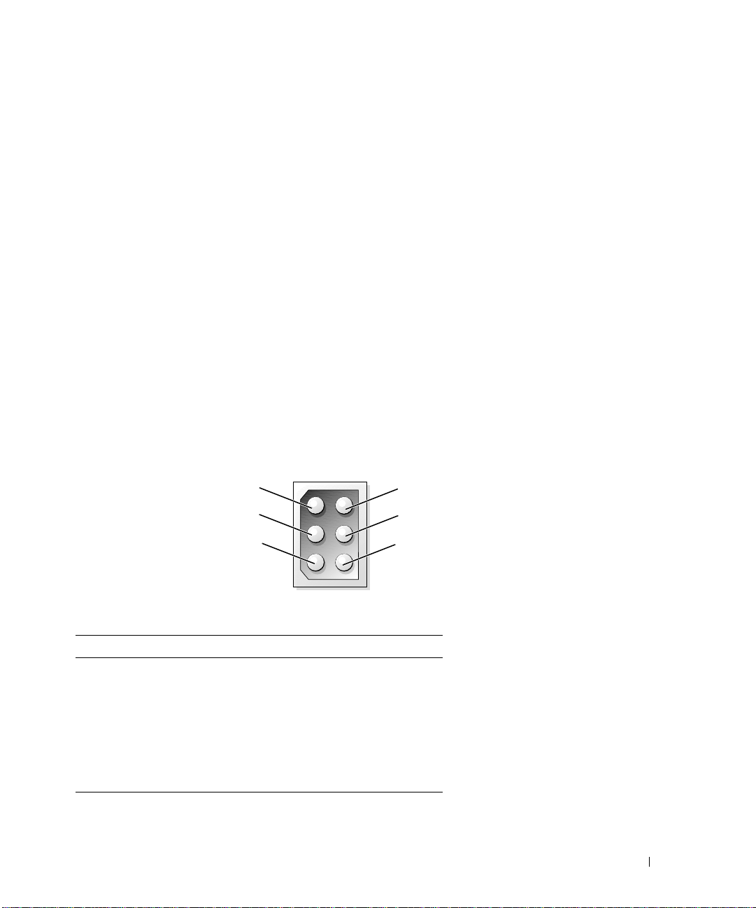
4 Insert the three black –48 VDC wires into connector housing positions 2, 3, and 6 (see
Figure 1-1 and Table 1-1).
5 Insert the three red –48 VDC return wires into connector housing positions 1, 4, and 5
(see Figure 1-1 and Table 1-1).
6 Slide the heat-shrink tubing over the DC power cable so that it overlaps the connector
housing by at least 6.35 mm (0.25 inches).
7 Using a heat gun, shrink the tubing around the cable and connector housing.
Figure 1-1. Connector Housing
front view
36
5
4
Table 1-1. Connector Housing Pin Assignments
Pin Description Wire Color and Size
1 –48 VDC return Red 16 AWG
2–48 VDC Black 16 AWG
3–48 VDC Black 16 AWG
4 –48 VDC return Red 16 AWG
5 –48 VDC return Red 16 AWG
6–48 VDC Black 16 AWG
2
1
Cabling Instructions for the –48 VDC 1-3
Page 6
Assembling the Safety Ground Wire
1 Strip the insulation from the end of the green/yellow wire, exposing approximately
4.5 mm (0.175 inches) of copper wire.
2 Using a hand-crimping tool, crimp the ring-tongue terminal to the green/yellow wire.
Connecting the –48 VDC Power Cable and Safety Ground
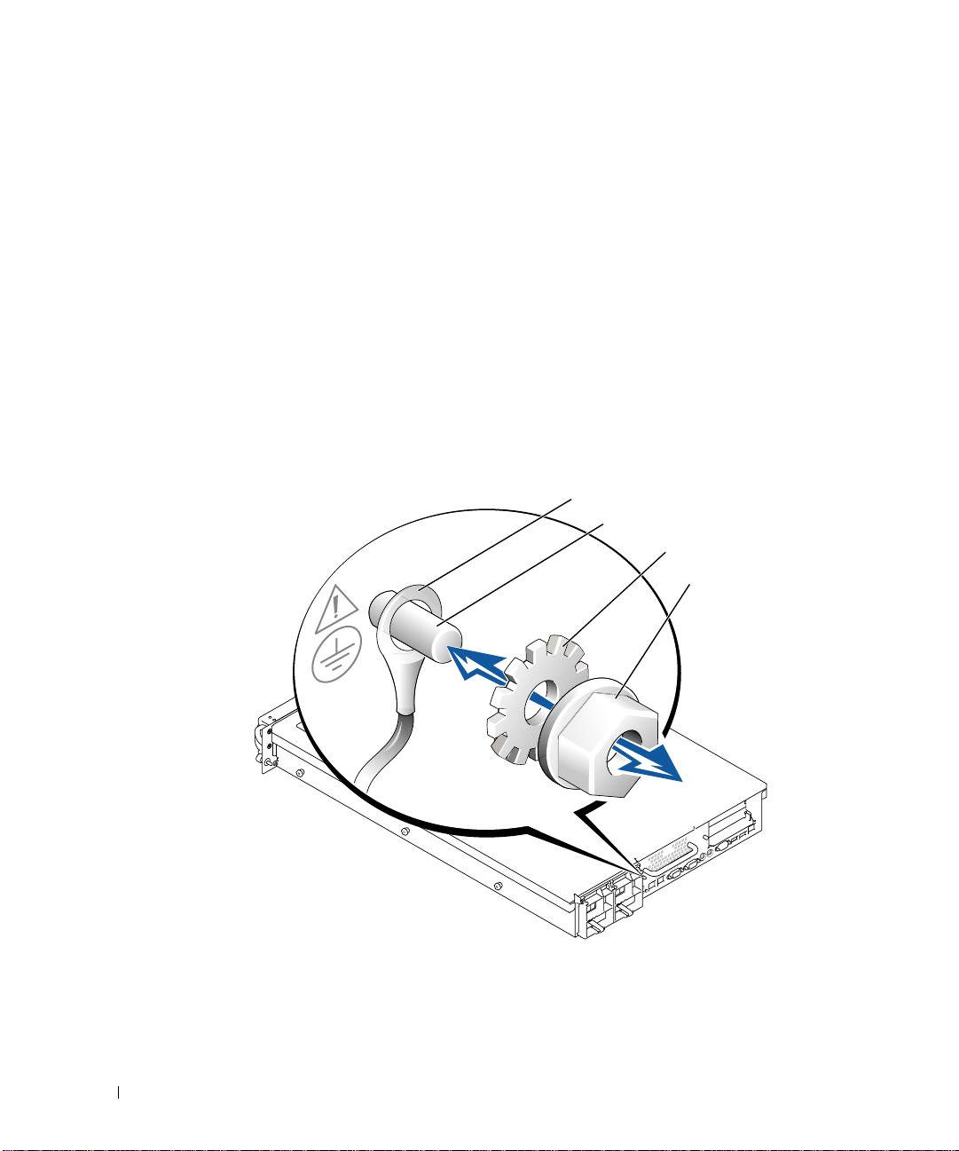
1 Connect the safety ground to the grounding post on the back of the system using a
www.dell.com | support.dell.com
#6-32 nut equipped with a locking washer (see Figure 1-2).
2 Plug the DC power cable into the system.
Figure 1-2. Safety Ground
safety ground
grounding post
lock washer
#6-32 nut
1-4 Cabling Instructions for the –48 VDC
Page 7

Page 8

Printed in the U.S.A.
00R216A00
P/N 0R216 Rev. A00
www.dell.com | support.dell.com
 Loading...