

Page 1

Dell PowerConnect
M8024-k Switch
Getting Started Guide
使用入门指南
入門指南
Guide de mise en route
Handbuch zum Einstieg
Panduan Pengaktifan
はじめに
시작 안내서
Guía de introducción
Başlangıç Kılavuzu
Regulatory Model: PCM8024-k
ʪʩʸʣʮʺʬʩʧʺʤʣʥʡʲʤ
Guia de Primeiros Passos
Page 2

Page 3

Dell PowerConnect
M8024-k Switch
Getting Started Guide
Regulatory Model: PCM8024-k
Page 4

Notes
NOTE: A NOTE indicates important information that helps you make better use of
your computer.
____________________
Information in this publication is subject to change without notice.
© 2010 Dell Inc. All rights reserved.
Reproduction of these materials in any manner whatsoever without the written permission of Dell Inc.
is strictly forbidden.
Trademarks used in this text: Dell™, the DELL logo, PowerConnect™, OpenManage™, are
trademarks of Dell Inc. Microsoft
in the United States and/or other countries.
Other trademarks and trade names may be used in this publication to refer to either the entities claiming
the marks and names or their products. Dell Inc. disclaims any proprietary interest in trademarks and
trade names other than its own.
Regulatory Model PCM8024-k
March 2011 P/N 7XG64 Rev. A00
®
, Windows® are registered trademarks of Microsoft Corporation
Page 5

Contents
1 Introduction . . . . . . . . . . . . . . . . . . . . . . . . 5
PowerConnect M8024-k Overview . . . . . . . . . . . . 5
2 Hardware Overview. . . . . . . . . . . . . . . . . . 6
Internal Ports. . . . . . . . . . . . . . . . . . . . . . . . 6
Front Panel
. . . . . . . . . . . . . . . . . . . . . . . . . 6
SFP+ Ports
Expansion Slot
USB Console Port
Port and System LEDs
. . . . . . . . . . . . . . . . . . . . . . 7
. . . . . . . . . . . . . . . . . . . . 7
. . . . . . . . . . . . . . . . . . . 7
. . . . . . . . . . . . . . . . 7
3 Installation . . . . . . . . . . . . . . . . . . . . . . . . 8
Site Preparation . . . . . . . . . . . . . . . . . . . . . . 8
Unpacking the Switch
Package Contents
Unpacking Steps
. . . . . . . . . . . . . . . . . . . 9
. . . . . . . . . . . . . . . . . . 9
. . . . . . . . . . . . . . . . . . . 9
Contents 3
Page 6

4 Starting and Configuring the Switch . . . 10
Connecting a Switch to a Terminal . . . . . . . . . . . 11
Booting the Switch
. . . . . . . . . . . . . . . . . . . . 12
Performing the Initial Configuration
Initial Configuration Procedure
Example Session
Next Steps
. . . . . . . . . . . . . . . . . . 14
. . . . . . . . . . . . . . . . . . . . . 17
. . . . . . . . . . . 13
. . . . . . . . . . . 13
4 Contents
Page 7

Introduction
This document provides basic information about the Dell PowerConnect
M8024-k switches, including how to install a switch and perform the initial
configuration. For information about how to configure and monitor switch
features, see the User’s Configuration Guide, which is available on the Dell
Support website at http://support.dell.com/manuals for the latest updates on
documentation and firmware.
This document contains the following sections:
• Hardware Overview
• Installation
• Starting and Configuring the Switch
PowerConnect M8024-k Overview
The PowerConnect M8024-k is a Layer 3, 10-Gigabit Ethernet blade switch
that operates in the PowerEdge M1000e system. The M1000e system can
support up to 16 server blades and six PowerConnect M8024-k blade
switches.
Getting Started Guide 5
Page 8
Hardware Overview
This section contains information about device characteristics and modular
hardware configurations for the PowerConnect M8024-k switches.
PowerConnect M8024-k has the following physical dimensions:
• 274.75 x 309.24 x 33.45 mm (W x D x H).
• 10.81 x 12.17 x 1.32 inches (W x D x H).
Internal Ports
PowerConnect M8024-k provides 16 internal 10-Gigabit Ethernet internal
ports. The 16 internal ports are connected to server blades through the
M1000e chassis mid-plane.
The M8024-k also provides an internal Ethernet interface—the out-of-band
(OOB) interface—which is dedicated to switch management. The OOB
interface is connected to the chassis management controller through the
chassis mid-plane. Traffic on this port is segregated from operational network
traffic on the switch ports and cannot be switched or routed to the
operational network.
Front Panel
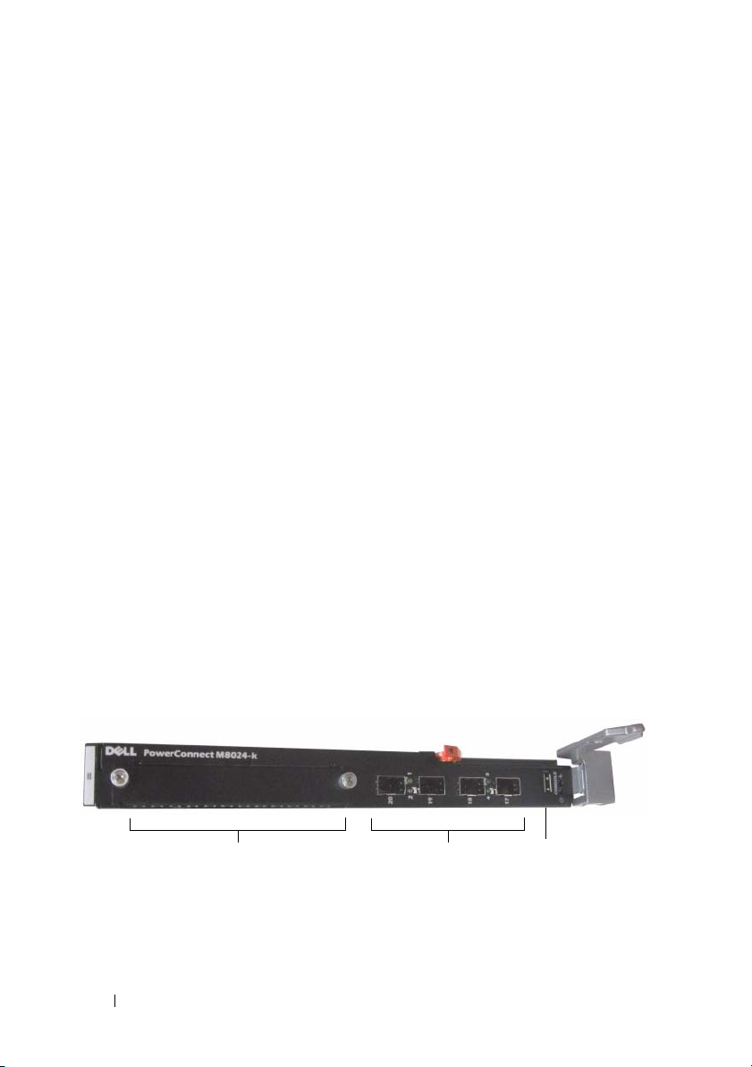
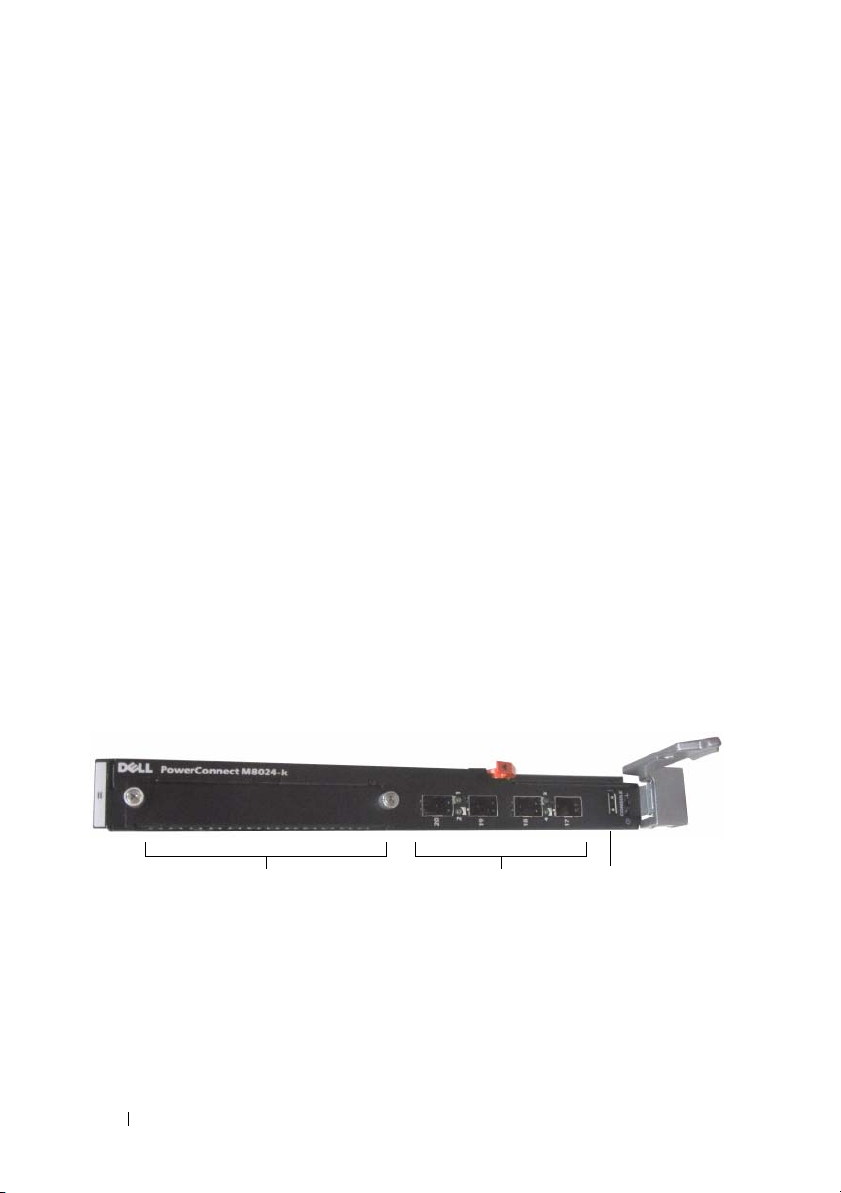
The following image shows the PowerConnect M8024-k front panel:
Figure 1-1. PowerConnect M8024-k Front Panel
USB Console PortSFP+ PortsExpansion Slot
The front panel includes four SFP+ ports an expansion slot for 10-Gigabit
modules. The front panel also provides a USB serial console interface for
management functions and LEDs for port and system status.
6 Getting Started Guide
Page 9
SFP+ Ports
PowerConnect M8024-k provides four SFP+ ports with SR, LR, and LRM
transceivers and SFP+ direct attach cables. SFP transceivers and direct
attach cables are sold separately.
Expansion Slot
The 10G expansion slot supports the following modules:
• SFP+ (four ports)
• CX-4 (three ports)
• 10GBASE-T (two ports)
The modules are sold separately.
USB Console Port
The USB console port is for management through an RS-232serial interface.
This port provides a direct connection to the switch and allows you to access
the CLI from a console terminal connected to the port through the provided
serial cable (with USB type-A to female DB-9 connectors).
The console port supports asynchronous data of eight data bits, one stop bit, no
parity bit, and no flow control. The default baud rate is 9600 bps.
Port and System LEDs
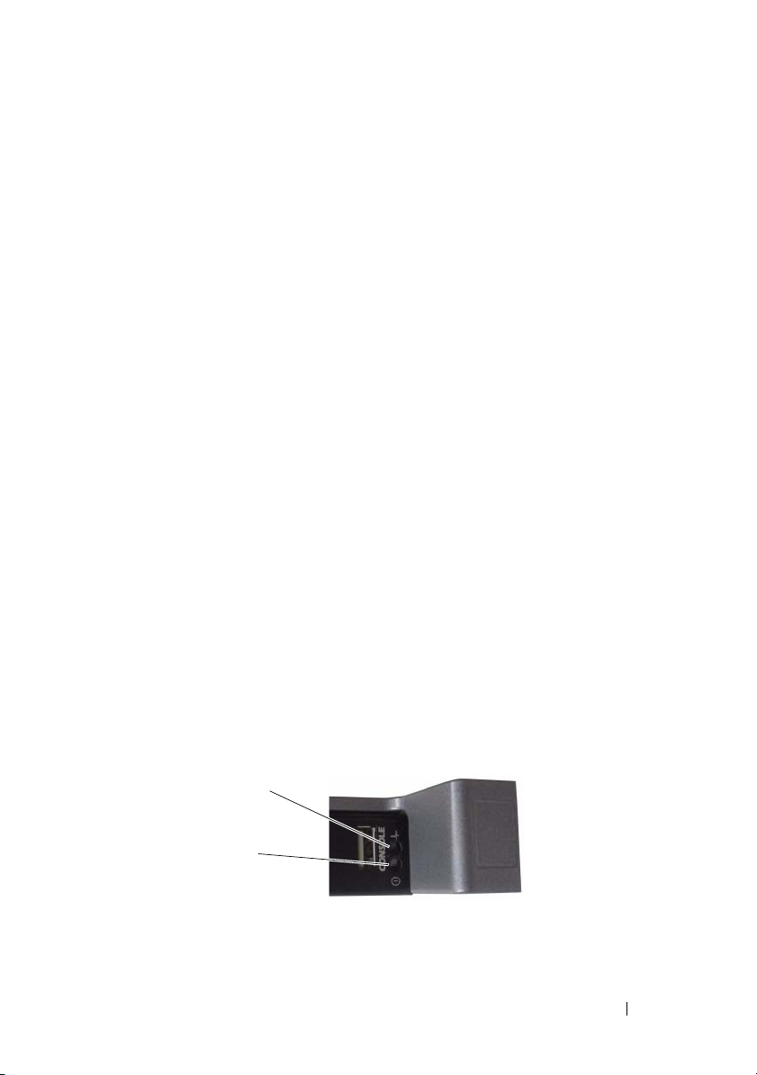
The front panel contains light emitting diodes (LEDs) that provide
information about the status of the PowerConnect M8024-k unit.
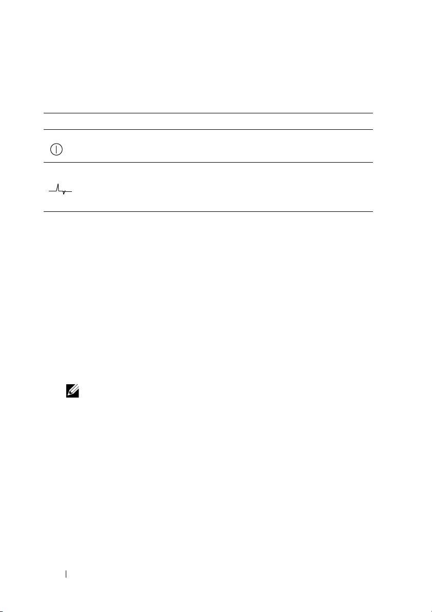
Figure 1-2. Front Panel LEDs
System Status LED
System Power LED
Getting Started Guide 7
Page 10
Table 1-1 contains the status LED definitions:
Table 1-1. PowerConnect M8024-k Power and Status LED Definitions
LED Color Definition
Green Power is being supplied to the switch.
Off The switch does not have power.
Blue The switch is operating normally.
Off The switch is powered off.
Amber A fault has occurred, or the switch is currently booting.
Installation
Site Preparation
Before installing the switch or switches, make sure that the chosen
installation location meets the following site requirements:
•
Clearance
access. Allow clearance for cabling, power connections, and ventilation.
Cabling
•
as radio transmitters, broadcast amplifiers, power lines, and fluorescent
lighting fixtures.
•
Ambient Temperature
range is 10° to 35ºC (50° to 95ºF).
— There is adequate front and rear clearance for operator
— The cabling is routed to avoid sources of electrical noise such
— The ambient switch operating temperature
NOTE: Decrease the maximum temperature by 1°C (1.8°F) per 300 m (985 ft.)
above 900 m (2955 ft.).
•
Relative Humidity
(non-condensing) with a maximum humidity gradation of 10% per hour.
8 Getting Started Guide
— The operating relative humidity is 8% to 85%
Page 11

Unpacking the Switch
Package Contents
When unpacking each switch, make sure that the following items are
included:
• One PowerConnect switch
• One USB type A-to-DB-9 female cable
• Getting Started Guide
• Safety and Regulatory Information
• Warranty and Support Information
• Software License Agreement
Unpacking Steps
NOTE: Before unpacking the switch, inspect the container and immediately report
any evidence of damage.
1
Place the container on a clean, flat surface and cut all straps securing the
container.
2
Open the container or remove the container top.
3
Carefully remove the switch from the container and place it on a secure
and clean surface.
4
Remove all packing material.
5
Inspect the product and accessories for damage.
Getting Started Guide 9
Page 12

Starting and Configuring the Switch
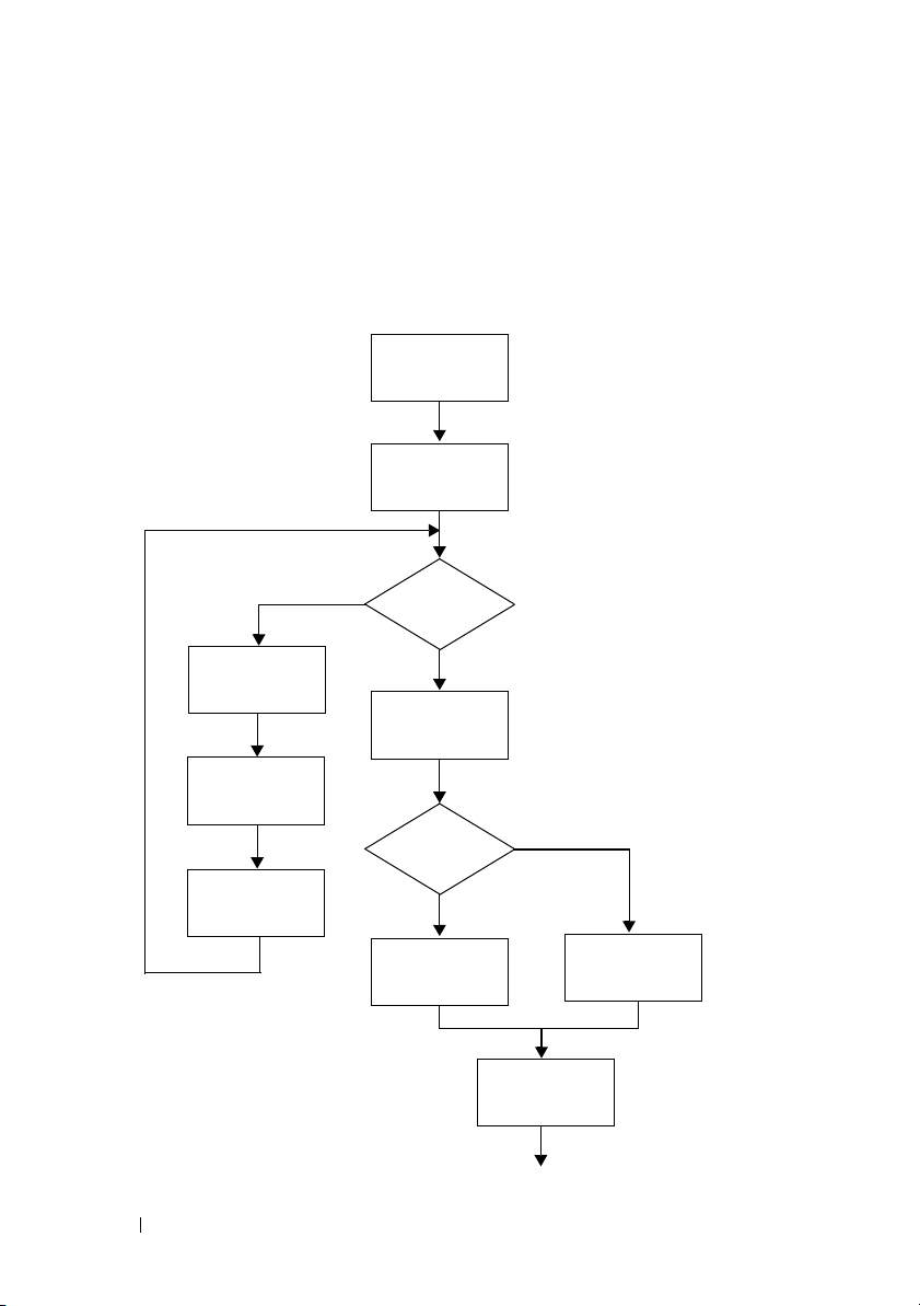
The following flow chart provides an overview of the steps you use to perform
the initial configuration after the switch is unpacked and mounted.
Figure 1-3. Installation and Configuration Flow Chart
Connect Power
and Console
Power On
Yes
Choose Option 2
Boot Menu
(Special Functions)
Reboot
10 Getting Started Guide
Enter Boot
Menu?
No
Loading Program
from Flash to RAM
Enter
Wizard?
No
Manual Initial
Configuration
Yes
Easy Setup Wizard
Configuration
Advanced
Configuration
Page 13

Connecting a Switch to a Terminal
After completing all external connections, connect a terminal to a switch to
configure the switch.
NOTE: Read the release notes for this product before proceeding. You can
download the release notes from the Dell Support website at
support.dell.com/manuals.
NOTE: We recommend that you obtain the most recent version of the user
documentation from the Dell Support website at http://support.dell.com/manuals.
To monitor and configure the switch via serial console, use the USB console
port on the front panel of the switch (see Figure 1-1) to connect it to a VT100
terminal or to a computer running VT100 terminal emulation software. The
console port is implemented as a data terminal equipment (DTE) connector.
The following equipment is required to use the console port:
• VT100-compatible terminal or a desktop or a portable computer with a
serial port running VT100 terminal emulation software,
HyperTerminal.
• A serial cable (provided) with a USB type-A connector for the console port
and DB-9 connector for the terminal.
Perform the following tasks to connect a terminal to the switch console port:
1
Connect the DB-9 connector on the serial cable to the terminal or
computer running VT100 terminal emulation software.
2
Configure the terminal emulation software as follows:
a
Select the appropriate serial port (for example, COM 1) to connect to
the console.
b
Set the data rate to 9600 baud.
c
Set the data format to 8 data bits, 1 stop bit, and no parity.
d
Set the flow control to none.
e
Set the terminal emulation mode to
f
Select Terminal keys for Function, Arrow, and Ctrl keys. Ensure that
VT100
.
the setting is for Terminal keys (not Microsoft Windows keys).
such as Microsoft
Getting Started Guide 11
Page 14
NOTE: When using HyperTerminal with Microsoft Windows 2000, make sure
that you have Windows 2000 Service Pack 2 or later installed. With Windows
2000 Service Pack 2, the arrow keys function properly in HyperTerminal's
VT100 emulation. Go to microsoft.com for more information about Windows
2000 service packs.
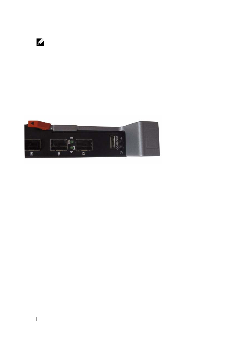
3
Connect the USB connector on the cable directly to the switch console
port. The PowerConnect M8024-k console port is located on the right side
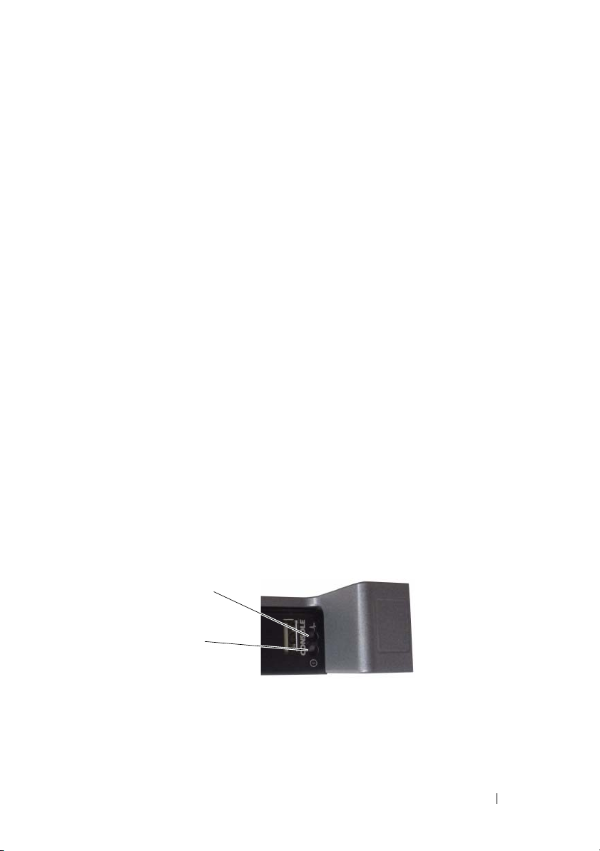
of the front panel, as shown in Figure 1-4.
Figure 1-4. PowerConnect M8024-k USB Console Port
USB Console
Port
Booting the Switch
When the power is turned on with the local terminal already connected, the
switch goes through a power-on self-test (POST). POST runs every time the
switch is initialized and checks hardware components to determine if the
switch is fully operational before completely booting. If POST detects a
critical problem, the program flow stops. If POST passes successfully, valid
firmware is loaded into RAM. POST messages are displayed on the terminal
and indicate test success or failure. The boot process runs for approximately
60 seconds.
You can invoke the Boot menu after the first part of the POST is completed.
From the Boot menu, you can perform configuration tasks such as resetting
the system to factory defaults, activating the backup image, or recovering a
password. For more information about the Boot menu functions, see the CLI
Reference Guide.
12 Getting Started Guide
Page 15

Performing the Initial Configuration
The initial configuration procedure is based on the following assumptions:
• The PowerConnect switch was never configured before and is in the same
state as when you received it.
• The PowerConnect switch booted successfully.
• The console connection was established, and the
prompt appears on the screen of a VT100 terminal or terminal equivalent.
The initial switch configuration is performed through the console port. After
the initial configuration, you can manage the switch from the alreadyconnected console port or through a remote connection.
NOTE: The switch is not configured with a default user name, password, or IP
address.
Before setting up the initial configuration of the switch, obtain the following
information from your network administrator:
• The IP address to be assigned to the out-of-band (OOB) interface for
device management.
• The IP subnet mask for the OOB interface.
• The IP address of the OOB interface default gateway.
These settings are necessary to allow the remote management of the switch
through Telnet (Telnet client) or HTTP (Web browser).
Dell Easy Setup Wizard
Initial Configuration Procedure
You can perform the initial configuration by using the Dell Easy Setup
Wizard or by using the CLI. The wizard automatically starts when the switch
configuration file is empty. You can exit the wizard at any point by entering
[ctrl+z], but all configuration settings specified will be discarded, and the
switch will use the default values.
NOTE: If you do not run the Easy Setup Wizard or do not respond to the initial Easy
Setup Wizard prompt within 60 seconds, the switch enters CLI mode.
For more information about performing the initial configuration by using the
CLI, see the CLI Reference Guide. This Getting Started Guide shows how to
use the Easy Setup Wizard for initial switch configuration. The wizard sets up
the following configuration on the switch:
Getting Started Guide 13
Page 16

• Establishes the initial privileged user account with a valid password. The
wizard configures one privileged user account during the setup.
• Enables CLI login and HTTP access to use the local authentication setting
only.
• Sets up the IP address for the OOB interface.
• Sets up the SNMP community string to be used by the SNMP manager at
a given IP address. You may choose to skip this step if SNMP management
is not used for this switch.
Example Session
This section describes an Easy Setup Wizard session. The following values are
used by the example session:
• SNMP is not enabled.
• The default user name,
entered. The Wizard does not display the password as it is entered.
• The OOB management interface uses
assignment.
NOTE: In the example below, the possible user options or default values are
enclosed in [ ]. If you press <Enter> with no options defined, the default value is
accepted. Help text is in parentheses.
The following example contains the sequence of prompts and responses
associated with running an example Dell Easy Setup Wizard session, using
the input values listed above.
After the switch completes the POST and is booted, the following text is
displayed:
(Unit 1 - Waiting to select management unit)>
root
, is accepted and a password of
192.168.2.1
admin123
for IP address
is
Applying Global configuration, please wait ...
Welcome to Dell Easy Setup Wizard
The Setup Wizard guides you through the initial switch
configuration, and gets you up and running as quickly
as possible. You can skip the setup wizard, and enter
CLI mode to manually configure the switch. You must
respond to the next question to run the setup wizard
within 60 seconds, otherwise the system will continue
14 Getting Started Guide
Page 17

with normal operation using the default system
configuration. Note: You can exit the setup wizard at
any point by entering [ctrl+z].
Would you like to run the setup wizard (you must
answer this question within 60 seconds)? [Y/N] y
First:
Do you want to select the operational mode as Simple
Mode? [Y/N] y
Step 1:
The system is not setup for SNMP management by
default. To manage the switch using SNMP (required for
Dell Network Manager) you can
. Set up the initial SNMP version 2 account now.
. Return later and setup other SNMP accounts. (For
more information on setting up an SNMP version 1
or 3 account, see the user documentation).
Would you like to setup the SNMP management interface
now? [Y/N] n
Step 2:
Now we need to setup your initial privilege (Level 15)
user account. This account is used to login to the CLI
and Web interface. You may setup other accounts and
change privilege levels later. For more information on
setting up user accounts and changing privilege
levels, see the user documentation.
To setup a user account:
Please enter the user name. [root]:
Please enter the user password:
Please reenter the user password:
Getting Started Guide 15
Page 18

Step 3:
Next, IP addresses are setup on the OOB (Out-Of-Band)
Interface and/or the VLAN1 routing interface.
You can use these IP addresses to access the CLI, Web
interface, or SNMP interface of the switch.
To access the switch through any Management Interface
you can
. Setup the IP address for the Management Interface.
. Setup the default gateway if IP address is
manually configured on both routing and OOB
interface.
Would you like to setup the Out-Of-Band interface now?
[Y/N] y
Please enter the IP address of the device (A.B.C.D) or
enter "DHCP" (without the quotes) to automatically
request an IP address from the network DHCP server.
[192.168.2.1]:
Please enter the IP subnet mask (A.B.C.D or /nn).
[255.255.255.0]:
This is the configuration information that has been
collected:
Operational Mode = Simple
User Account setup = root
Password = ********
Out-of-band IP address = 192.168.2.1 255.255.255.0
Final Step:
If the information is correct, please enter (Y) to
save the configuration, and copy the settings to the
start-up configuration file. If the information is
incorrect, enter (N) to discard the configuration and
restart the wizard: [Y/N] y
16 Getting Started Guide
Page 19

Thank you for using the Dell Easy Set up Wizard. You
will now enter CLI mode.
Applying Interface configuration, please wait ...
console>
Next Steps
After completing the initial configuration described in this section, you can
connect any of the front-panel switch ports to your production network for
in-band remote management.
If you specified DHCP for the OOB management interface IP address, the
interface will acquire its IP address from a DHCP server on the network. To
discover the dynamically-assigned IP address, use the console port connection
to issue the following command:
show ip interface out-of-band.
To access the Dell OpenManage Switch Administrator interface, enter the
OOB management interface IP address into the address field of a Web
browser. For remote management access to the CLI, enter the OOB
management interface IP address into a Telnet or SSH client. Alternatively,
you can continue to use the console port for local CLI access to the switch.
Your PowerConnect M8024-k switch supports basic switching features such as
VLANs, 802.1X, RADIUS and TACACS+. For more information on the
features supported in Simple mode, refer to Simple Switch Mode: Port
Aggregator Feature White Paper.
If the switch is configured to operate in Normal mode, it can also support
features such as spanning tree protocol, as well as advanced Layer 3 features
such as dynamic routing and multicast. Use the web-based management
interface or the CLI to configure the features your network requires. For
information about how to configure the switch features, see the User’s
Configuration Guide or CLI Reference Guide available on the support site:
http://support.dell.com/manuals.
Getting Started Guide 17
Page 20

18 Getting Started Guide
Page 21

Dell PowerConnect
M8024-k 交换机
使用入门指南
管制型号:
PCM8024-k
Page 22

注
注:“注”表示可以帮助您更好地使用计算机的重要信息。
____________________
本出版物中的信息如有更改,恕不另行通知。
© 2010 Dell Inc.
未经
Dell Inc.
本文中使用的商标:
标
Microsoft
本出版物中述及的其它商标和产品名称是指拥有相应商标和产品名称的公司或其制造的
产品。
Dell Inc.
管制型号
PCM8024-k
2011 年 3 月P/N 7XG64 Rev. A00
版权所有,翻印必究。
书面许可,严禁以任何形式对这些材料进行复制。
Dell™, DELL 徽标, PowerConnect™, OpenManage™, 是 Dell Inc.
®
, Windows® 是 Microsoft Corporation
对其它公司的商标和产品名称不拥有任何所有权。
在美国和/或其它国家或地区的注册商标。
的商
Page 23

目录
1 简介 . . . . . . . . . . . . . . 23
2 硬件概览 . . . . . . . . . . . . 24
3 安装 . . . . . . . . . . . . . . 26
. . . . . . . . . . . . . 23
PowerConnect M8024-k
内部端口 . . . . . . . . . . . . . . . . . . . . . . 24
前面板
. . . . . . . . . . . . . . . . . . . . . . . 24
SFP+ 端口 . . . . . . . . . . . . . . . .
扩充槽 . . . . . . . . . . . . . . . . .
USB 控制台端口 . . . . . . . . . . . . .
端口和系统 LED
概览
25
25
25
. . . . . . . . . . . . . . . . 25
现场准备 . . . . . . . . . . . . . . . . . . . . . . 26
打开交换机包装
包装箱物品 . . . . . . . . . . . . . . .
打开包装步骤 . . . . . . . . . . . . . .
. . . . . . . . . . . . . . . . . . . 27
27
27
目录 21
Page 24

4 启动和配置交换机 . . . . . . . . 28
将交换机连接至终端 . . . . . . . . . . . . . . . . 29
引导交换机
进行初始配置
. . . . . . . . . . . . . . . . . . . . . 30
. . . . . . . . . . . . . . . . . . . . 30
初始配置步骤 . . . . . . . . . . . . . . .
示例会话 . . . . . . . . . . . . . . . . .
接下来的步骤 . . . . . . . . . . . . . . .
31
31
34
22 目录
Page 25

简介
本说明文件介绍有关
括如何安装交换机并进行初始配置。 有关如何配置和监测交换机功能的
信息,请参阅
置指南)。要获取有关说明文件及固件的最新更新,请访问该站点,网址
为
http://support.dell.com/manuals.
本说明文件包含以下部分:
•
硬件概览
•
安装
•
启动和配置交换机
Dell
PowerConnect M8024-k
PowerConnect M8024-k
千兆位以太网刀片式交换机。
和
6 个 PowerConnect M8024-k
Dell PowerConnect M8024-k
支持
Web
站点上的
Users Configuration Guide, (
概览
是在
PowerEdge M1000e
M1000e
刀片式交换机。
系统可支持多达
交换机的基本信息,包
用户配
系统上运行的第
16
3 层 10
个服务器刀片
使用入门指南 23
Page 26
硬件概览
本节包含有关
的信息。
PowerConnect M8024-k
•
274.75 x 309.24 x 33.45
•
10.81 x 12.17 x 1.32
PowerConnect M8024-k
的物理尺寸如下所示:
毫米(宽
英寸(宽
交换机设备特性和模块化硬件配置
高)。
x 厚 x
高)。
x 厚 x
内部端口
PowerConnect M8024-k
部端口通过
M8024-k
进行交换机管理。
此端口上的通信与交换机端口上的运行网络通信是分开的,并且不能切换
或路由到运行网络。
M1000e
还提供了内部以太网接口,即带外
提供
16 个 10
机箱中间面板连接到服务器刀片。
接口通过机箱中间面板连接到机箱管理控制器。
OOB
千兆位以太网内部端口。这
(OOB)
接口。该接口专用于
16
个内
前面板
下图表示
图
1-1. PowerConnect M8024-k
PowerConnect M8024-k
前面板:
前面板
前面板包含
提供
1
接口。
24 使用入门指南
4 个 SFP+
个用于管理功能和端口以及系统状态
端口以及
1 个 10
USB 控制台端口SFP+ 端口扩充槽
千兆位模块的扩充槽。前面板还
LED 的 USB
串行控制台
Page 27
端口
SFP+
PowerConnect M8024-k
口和
SFP+
直连电缆。
提供
SFP
个具有
4
收发器和直连电缆单独出售。
SR、LR 及 LRM
收发器的
SFP+
端
扩充槽
扩充槽支持下列模块:
10G
•
•
•
这些模块单独出售。
USB
USB
接连接到交换机,并可从通过提供的串行电缆连接到此端口(
内孔
控制台端口支持八个数据位、一个停止位、无奇偶校验位以及无流控制的异
步数据。默认波特率为
(4 个端口)
SFP+
(3 个端口)
CX-4
10GBASE-T
(2 个端口)
控制台端口
控制台端口用于通过
连接器)的控制台终端来访问
DB-9
RS-232
9600 bps。
串行接口进行管理。可以借助此端口直
类到
CLI
USB A
。
端口和系统
前面板包含若干发光二极管
单元的状态信息
图
1-2.
LED
。
前面板
LED
系统状态 LED
系统电源 LED
,用于提供关于
(LED)
PowerConnect M8024-k
使用入门指南 25
Page 28
表
包含了状态
1-1
LED
说明:
表
1-1. PowerConnect M8024-k
LED
颜色
绿色 正在为交换机供电。
关闭 交换机已断电。
蓝色 交换机工作正常。
关闭 交换机电源关闭。
琥珀色 出现故障,或交换机当前正在引导。
定义
电源和状态
LED
说明
安装
现场准备
安装交换机之前,请确保选择的安装位置满足以下现场要求:
•
空间 正面和背面有足够空间供操作员进行操作。留出用于布线、电源
连接以及通风的空间。
布线 布线应远离电气噪音干扰源,如无线电发射器、广播放大器、电
•
线以及荧光照明装置。
环境温度
•
注:在 900 米(2955 英尺)以上,每升高 300 米(985 英尺)最高温度
•
相对湿度 运行相对湿度为
为每小时
交换机的运行环境温度范围为
下降 1C (1.8F)。
。
10%
8% 到 85%
10 到 35C (50 到 95F).
(非冷凝),最大湿度变化梯度
26 使用入门指南
Page 29

打开交换机包装
包装箱物品
打开每台交换机的包装时,请确保其中包含以下物品:
•
一台
PowerConnect
•
一根
USB A
•
使用入门指南
•
安全和管制信息
•
保修和支持信息
•
软件许可协议
类至
交换机
DB-9
内孔电缆
打开包装步骤
注:在打开交换机的包装之前,先检查包装盒,如有任何损坏迹象,请立
即报告。
将包装盒放在整洁平坦的表面上,然后剪断固定包装盒的所有包装
1
带。
打开包装盒或取下包装盒盖。
2
从包装盒中小心取出交换机,然后将其放在稳固整洁的表面上。
3
取出所有包装材料。
4
检查产品及附件是否出现损坏。
5
使用入门指南 27
Page 30
启动和配置交换机
以下流程图概述了在打开交换机包装并安装好交换机之后,用于进行初始
配置的步骤。
图
安装和配置流程图
1-3.
选择选项 2
引导菜单
(特殊功能)
重新引导
是
连接电源和控
制台
开机
进入引导
菜单?
否
将程序从闪存载
入到 RAM
进入
向导?
否
是
28 使用入门指南
手动初始配置
简易安装向
导配置
高级配置
Page 31

将交换机连接至终端
完成所有外部连接后,将终端连接至交换机以配置该交换机。
注:在继续操作之前,请阅读本产品的版本注释。可以从 Dell 支持 Web 站
点 support.dell.com/manuals 下载版本注释。
注:我们建议您从 Dell 支持 Web 站点 http://support.dell.com/manuals 获取最
新版本的用户说明文件。
要通过串行控制台监测和配置交换机,请使用交换机前面板上的
制台端口(请参阅图
VT100
终端仿真软件的计算机。控制台端口可用作数据终端设备
连接器。
要使用控制台端口,需要以下设备:
•
•
兼容终端,或者一台配备串行端口并运行
VT100
如
(
Microsoft HyperTerminal
一根串行电缆(附带),带有连接控制台端口的
接终端的
DB-9
要将终端连接至交换机控制台端口,请执行以下任务:
将串行电缆上的
1
算机相连。
按照以下步骤配置终端仿真软件:
2
a
选择适当的串行端口(例如
b
将数据速率设置为
c
将数据格式设置为
d
将流控制设置为
e
将终端仿真模式设置为
f
选择终端键作为功能键、箭头键和
端键(而不是
注:在 Microsoft Windows 2000 中使用超级终端时,请确保已安装
Windows 2000 Service Pack 2 或更高版本。使用 Windows 2000 Service
Pack 2 可以确保箭头键在超级终端的 VT100 仿真中正常工作。有关
Windows 2000 Service Pack 的详情,请访问 microsoft.com。
将电缆上的
3
M8024-k
USB
控制台端口位于前面板右侧,如图
),将交换机连接至
1-1
VT100
终端或正在运行
VT100
)的台式机或便携式计算机。
USB A
连接器。
连接器与运行
DB-9
COM 1
波特。
9600
个数据位、1 个停止位以及无奇偶校验。
8
(无)。
none
VT100
Microsoft Windows
VT100
。
终端仿真软件的终端或计
)连接到控制台。
键。确保此设置适用于终
Ctrl
键)。
连接器直接连接到交换机控制台端口。
中所示。
1-4
终端仿真软件
类连接器和连
PowerConnect
控
USB
(DTE)
使用入门指南 29
Page 32

图
1-4. PowerConnect M8024-k USB
引导交换机
控制台端口
USB 控制台
端口
打开电源并连接本地终端后,交换机将进行开机自测
每次初始化交换机时进行,用于检查硬件组件,以确定交换机在完全引导
之前是否完全正常运转。如果
如果
POST
示在终端上,用于指出自测是否成功。引导过程大约运行
在
POST
导)菜单中,您可以执行配置任务,例如将系统重置为出厂默认值、激活
备份映像或者恢复密码。有关
《
CLI
成功通过,将载入一个有效的固件到
第一部分完成后,可以调用
参考指南》。
POST
Boot
检测到严重问题,程序流就会停止。
(引导)菜单。从
Boot
(引导)菜单功能的详情,请参阅
(POST)。POST
中。
RAM
60
POST
秒。
Boot
在
信息显
(引
进行初始配置
初始配置步骤基于以下假设条件:
•
PowerConnect
相同。
•
PowerConnect
•
控制台连接已建立,并且
终端或同等终端设备的屏幕上。
通过控制台端口执行初始交换机配置。完成初始配置后,可以通过已连接
的控制台端口或远程连接管理交换机。
注:交换机未配置默认的用户名、密码和 IP 地址。
交换机此前从未进行过任何配置,其状态与收到时
交换机引导成功。
简易安装向导
Dell
提示信息显示在
VT100
30 使用入门指南
Page 33

在设置交换机的初始配置之前,从网络管理员处获得以下信息:
•
要分配给带外
•
OOB
•
OOB
要通过
Telnet(Telnet
(OOB)
接口的
IP
接口默认网关的
接口进行设备管理的
子网掩码。
地址。
IP
客户端)或
IP
HTTP(Web
地址。
浏览器)来远程管理交换
机,需要这些设置。
初始配置步骤
可以使用
为空时,将自动启动该向导。可以随时通过输入
定的所有配置设置都将被丢弃,交换机将使用默认值。
注:如果不运行简易安装向导或在 60 秒内没有响应初始简易安装向导提
示,交换机会进入 CLI 模式。
有关使用
入门指南说明如何使用简易安装向导来进行初始交换机配置。该向导设置
交换机的以下配置:
•
建立拥有权限的初始用户帐户以及有效的密码。在安装过程中,该向
导将配置一个具有权限的用户帐户。
•
启用
•
设置
•
设置
该交换机不使用
简易安装向导或
Dell
进行初始配置的详情,请参阅《
CLI
登录和
CLI
OOB
SNMP
HTTP
接口的
IP
管理器在指定
SNMP
CLI
访问,以便仅使用本地验证设置。
地址。
地址要使用的
IP
管理,则可以选择跳过这一步。
来进行初始配置。当交换机配置文件
[ctrl+z]
CLI
退出向导,但指
参考指南》。本使用
SNMP
团体字符串。如果
示例会话
本节介绍了一个简易安装向导会话。示例会话将使用以下值:
•
•
•
注:在以下示例中,可能的用户选项或默认值包括在 [ ] 中。如果未定义选
以下示例包含与使用上面列出的输入值运行
(
Dell
未启用。
SNMP
默认用户名
已接受,而且密码
root
admin123
已输入。在输入密码
时,向导不会显示密码。
管理接口使用
OOB
项,按 <Enter> 键将接受默认值。帮助文本在括号中。
192.168.2.1
来分配
IP
地址。
Dell Easy Setup Wizard
简易安装向导)示例会话相关的提示序列和响应。
使用入门指南 31
Page 34

交换机完成
POST
并引导后,将显示以下文本信息:
(Unit 1 - Waiting to select management unit)>
Applying Global configuration, please wait ...
Welcome to Dell Easy Setup Wizard
The Setup Wizard guides you through the initial switch
configuration, and gets you up and running as quickly
as possible. You can skip the setup wizard, and enter
CLI mode to manually configure the switch. You must
respond to the next question to run the setup wizard
within 60 seconds, otherwise the system will continue
with normal operation using the default system
configuration. Note: You can exit the setup wizard at
any point by entering [ctrl+z].
Would you like to run the setup wizard (you must
answer this question within 60 seconds)? [Y/N] y
First:
Do you want to select the operational mode as Simple
Mode? [Y/N] y
Step 1:
The system is not setup for SNMP management by
default. To manage the switch using SNMP (required for
Dell Network Manager) you can
. Set up the initial SNMP version 2 account now.
. Return later and setup other SNMP accounts. (For
more information on setting up an SNMP version 1
or 3 account, see the user documentation).
Would you like to setup the SNMP management interface
now? [Y/N] n
Step 2:
Now we need to setup your initial privilege (Level 15)
user account. This account is used to login to the CLI
and Web interface. You may setup other accounts and
change privilege levels later. For more information on
setting up user accounts and changing privilege
levels, see the user documentation.
32 使用入门指南
Page 35

To setup a user account:
Please enter the user name. [root]:
Please enter the user password:
Please reenter the user password:
Step 3:
Next, IP addresses are setup on the OOB (Out-Of-Band)
Interface and/or the VLAN1 routing interface.
You can use these IP addresses to access the CLI, Web
interface, or SNMP interface of the switch.
To access the switch through any Management Interface
you can
. Setup the IP address for the Management Interface.
. Setup the default gateway if IP address is
manually configured on both routing and OOB
interface.
Would you like to setup the Out-Of-Band interface now?
[Y/N] y
Please enter the IP address of the device (A.B.C.D) or
enter "DHCP" (without the quotes) to automatically
request an IP address from the network DHCP server.
[192.168.2.1]:
Please enter the IP subnet mask (A.B.C.D or /nn).
[255.255.255.0]:
This is the configuration information that has been
collected:
Operational Mode = Simple
User Account setup = root
Password = ********
Out-of-band IP address = 192.168.2.1 255.255.255.0
使用入门指南 33
Page 36

Final Step:
If the information is correct, please enter (Y) to
save the configuration, and copy the settings to the
start-up configuration file. If the information is
incorrect, enter (N) to discard the configuration and
restart the wizard: [Y/N] y
Thank you for using the Dell Easy Set up Wizard. You
will now enter CLI mode.
Applying Interface configuration, please wait ...
console>
接下来的步骤
完成本节所述的初始配置后,您可以将任意前面板交换机端口连接到生产
网络以便进行带内远程管理。
如果指定
DHCP
口连接来发出以下命令:
show ip interface out-of-band
要访问
的地址字段中输入
问,请在
以继续使用控制台端口对交换机进行本地
您的
802.1X、RADIUS 和 TACACS+
请参阅简单交换机模式:端口聚合器功能白皮书。
如果将交换机配置为在普通模式下工
功能,以及高级第
的管理接口或
能的信息,请参阅
参考指南》 ,这些资料可从以下支持站点获取:
http://support.dell.com/manuals
DHCP
服务器获得
Dell OpenManage Switch Administrator
Telnet 或 SSH
PowerConnect M8024-k
来分配
地址。要发现动态分配的
IP
OOB
层功能(如动态路由和多点传送)。使用基于
3
可配置您的网络需要的功能。 有关如何配置交换机功
CLI
Users Configuration Guide (
管理接口
OOB
。
管理接口
客户端中输入
IP
交换机支持基本的交换功能,如
。有关在简单模式中支持的功能的详情,
。
地址,则该接口会从网络上的
IP
IP
界面,请在
地址。要对
OOB
作,也能支持诸如生成树协议之类的
CLI
管理接口
访问。
CLI
用户配置指南)或 《
地址,请使用控制台端
Web
进行远程管理访
地址。或者,可
IP
浏览器
VLAN
、
Web
CLI
34 使用入门指南
Page 37

Dell PowerConnect
M8024-k 交換機
入門指南
管制型號: PCM8024-k
Page 38

註
註:「註」指出可協助您善加利用電腦的重要資訊。
____________________
對本出版物中所含資訊之變更恕不另行通知。
© 2010 Dell Inc. 版權所有,翻印必究。
未經 Dell Inc. 之書面許可,不得以任何方式重製這些材料。
本文所用商標: Dell™、 DELL 標誌、 PowerConnect™ 以及 OpenManage™ 是 Dell Inc. 的
商標。 Microsoft
本出版物所述及之其他商標或品牌名稱,均各自分屬其商標或產品名稱之申請者或擁有者所
擁有。Dell Inc. 對本公司之外的商標和產品名稱不擁有任何專有權。
管制型號 PCM8024-k
2011 年 3 月 P/N 7XG64 Rev. A00
®
、 Windows® 是在美國和 / 或其他國家 / 地區的註冊商標。
Page 39

目錄
1 簡介 . . . . . . . . . . . . . . . . . . . . . . . . . 39
2 硬體概觀 . . . . . . . . . . . . . . . . . . . . . . 40
3 安裝 . . . . . . . . . . . . . . . . . . . . . . . . . 42
PowerConnect M8024-k 概 . . . . . . . . . . . . . . 39
內部連接埠 . . . . . . . . . . . . . . . . . . . . . 40
前面板
. . . . . . . . . . . . . . . . . . . . . . . 40
SFP+ 連接埠
擴充插槽
USB 主控台連接埠
連接埠和系統 LED
. . . . . . . . . . . . . . . . . . 41
. . . . . . . . . . . . . . . . . . . . 41
. . . . . . . . . . . . . . . 41
. . . . . . . . . . . . . . . 41
現場準備 . . . . . . . . . . . . . . . . . . . . . . 42
拆開交換機包裝
包裝箱物品
拆開包裝的步驟
. . . . . . . . . . . . . . . . . . . 43
. . . . . . . . . . . . . . . . . . 43
. . . . . . . . . . . . . . . . 43
目錄 37
Page 40

4 啟動和設定交換機 . . . . . . . . . . . . . . . 44
將交換機連接至終端 . . . . . . . . . . . . . . . . 45
啟動交換機
進行初始組態
初始組態程序
範例作業階段
接下來的步驟
. . . . . . . . . . . . . . . . . . . . . 46
. . . . . . . . . . . . . . . . . . . . 46
. . . . . . . . . . . . . . . . . 47
. . . . . . . . . . . . . . . . . 47
. . . . . . . . . . . . . . . . . 50
38 目錄
Page 41

簡介
本文件提供 Dell PowerConnect M8024-k 交換機的基本資訊,包括如何安
裝交換機並進行初始組態。 如需有關如何設定和監控交換機功能的資
訊,請參閱 Dell 支援網站上的 Users Configuration Guide, ( 使用者組態指
南 )。要獲取有關文件及韌體的最新更新,請造此網站,網址為
http://support.dell.com/manuals.
本文件包含以下部分:
•
硬體概觀
•
安裝
•
啟動和設定交換機
PowerConnect M8024-k 概
PowerConnect M8024-k 是在 PowerEdge M1000e 系統上行的第三層 10
Gigabit Ethernet 刀片交換機。M1000e 系統可支援多達 16 個伺服器刀片
和 6 個 PowerConnect M8024-k 刀片交換機。
入門指南 39
Page 42

硬體概觀
本節包含有關 PowerConnect M8024-k 交換機裝置特性和模組化硬體組態
的資訊。
PowerConnect M8024-k 具有以下物理尺寸:
• 274.75 x 309.24 x 33.45
• 10.81 x 12.17 x 1.32
內部連接埠
PowerConnect M8024-k 提供 16 個內部 10 Gigabit Ethernet 內部連接埠。
這 16 個內部連接埠透過 M1000e 機殼中間面板連接到伺服器刀片。
M8024-k 還提供內部 Ethernet 介面,即頻外 (OOB) 介面。該介面專用於
交換機管理。OOB 介面透過機殼中間面板連接到機殼管理控制器。此連
接埠上的資訊流量與交換機連接埠上的作業網路資訊流量是分開的,並且
不能切換或路由到作業網路。
前面板
以下影像顯示了 PowerConnect M8024-k 前面板:
圖 1-1. PowerConnect M8024-k 前面板
毫米 (寬
英寸 (寬
x 厚 x 高)
x 厚 x 高)
USB 主控台連接埠SFP+ 連接埠擴充插槽
前面板包含 4 個 SFP+ 連接埠和 1 個 10 Gigabit 模組的擴充插槽。前面板
還提供了一個用來管理功能和連接埠及系統狀態 LED 的 USB 序列主控台
介面。
40 入門指南
Page 43

SFP+ 連接埠
PowerConnect M8024-k 提供 4 個具有 SR、LR 和 LRM 收發器及 SFP+ 直
接連接電纜的 SFP+ 連接埠。SFP 收發器和直接連接電纜單獨出售。
擴充插槽
10G 擴充插槽支援下列模組:
• SFP+ (4
•CX-4 (3
• 10GBASE-T (2
這些模組單獨出售。
個連接埠
個連接埠
個連接埠
)
)
)
USB 主控台連接埠
USB 主控台連接埠用於透過 RS-232 序列介面進行管理。可以借助此連接
埠直接連接到交換機,並從透過提供的序列電纜 ( 具有 USB A 至內孔
DB-9 連接器 ) 連接到此連接埠的主控台終端來存取 CLI。
主控台連接埠支援八個資料位元、一個停止位元、無同位檢查位以及無流量
控制的非同步資料。預設傳輸速率為
9600 bps。
連接埠和系統 LED
前面板包含若干發光二極體 (LED)
單元的資訊
。
,用於提供有關
PowerConnect M8024-k
圖 1-2. 前面板 LED
系統狀態 LED
系統電源 LED
入門指南 41
Page 44

表 1-1 包含狀態 LED 定義:
表 1-1. PowerConnect M8024-k 電源和狀態 LED 定義
LED
顏色 定義
綠色 交換機已接通電源。
熄滅 交換機未接通電源。
藍色 交換機正常運作。
熄滅 交換機電源關閉。
黃色 發生故障或交換機目前正在啟動。
安裝
現場準備
安裝交換機之前,請確保選擇的安裝位置滿足以下現場要求:
•
空間 交換機前後有足夠的空間供操作人員操作。留出用於布線、電源
連接以及通風的空間。
布線 布線時應避開電噪音源,如無線電發射器、廣播擴音器、電線以
•
及螢光燈具等。
• 環境溫度 交換機運作的環境溫度範圍在 10° 到 35°C
(50° 到 95°F)。
註:在 900 米 (2955 英尺 ) 以上,每升高 300 米 (985 英尺 ) 最高溫度
°
下降 1
•
相對溼度 運作的相對溼度為
為每小時
C (1.8°F)。
10%
。
8% 到 85% (
非冷凝),最大濕度變化梯度
42 入門指南
Page 45

拆開交換機包裝
包裝箱物品
拆開每台交換機的包裝時,請確保其中包含以下物品:
•
一台
PowerConnect
•
一根
USB A 至 DB-9
•
入門指南
•
安全和管制資訊
•
保固和支援資訊
•
軟體授權協議
拆開包裝的步驟
註:在拆開交換機的包裝之前,先檢查包裝盒,如有任何損壞跡象,請立
即報告。
1
將包裝盒放在整潔平坦的表面上,然後剪斷固定包裝盒的所有包
裝帶。
2
拆開包裝盒或取下包裝盒蓋。
3
從包裝盒中小心地取出交換機,然後將其放在穩定且整潔的表面上。
4
取出所有包裝材料。
5
檢查產品及附件是否有損壞。
交換機
的內孔電纜
入門指南 43
Page 46

啟動和設定交換機
以下流程圖概述了在拆開交換機包裝並安裝好交換機之後,進行初始組態
所使用的步驟。
圖 1-3. 安裝和設定流程圖
連接電源和
主控台
開機
選擇選項 2
動功能表
( 特殊功能 )
重新動
是
進入動
功能表?
否
將程式從快閃記
憶體載入 RAM
進入
精靈?
否
手動初始組態
是
簡易設定精
靈組態
進階組態
44 入門指南
Page 47

將交換機連接至終端
完成所有外部連接之後,將終端連接至交換機以設定該交換機。
註:在繼續操作之前,請閱讀本產品的版本說明。版本說明可以從 Dell 支
援網站 support.dell.com/manuals 下載。
註:建議從 Dell 支援網站 http://support.dell.com/manuals 獲取最新版本的使
用者文件。
若要透過序列主控台監控和設定交換機,請使用交換機前面板上的 USB
主控台連接埠 ( 請參閱圖 1-1),將交換機連接至 VT100 終端或正在執行
VT100 終端模擬軟體的電腦。主控台連接埠可用作資料終端設備 (DTE)
連接器。
若要使用主控台連接埠,需要以下設備:
• VT100
•
執行下列工作以將終端連接至交換機主控台連接埠:
1
2
3
相容終端,或者一台配備序列連接埠並執行
(
如 Microsoft HyperTerminal) 的桌上型電腦或便式電腦。
體
一根序列電纜 (附帶),帶有連接控制台連接埠的
終端的
DB-9
連接器。
將序列電纜上的
DB-9
連接器與執行
VT100
VT100
USB A
連接器和連接
終端模擬軟體的終端或電
腦相連。
按照以下步驟設定終端模擬軟體:
a
選取適當的序列連接埠 (例如
b
將資料速率設定為
c
將資料格式設定為
d
將流量控制設定為
e
將終端模擬模式設定為 VT100
f
對於功能鍵、方向鍵和
適用於終端機按鍵
註:在 Microsoft Windows 2000 中使用超級終端時,請確保已安裝
Windows 2000 Service Pack 2 或更高版本。使用 Windows 2000 Service
Pack 2 可以確保箭頭鍵在超級終端的 VT100 模擬中正常工作。請瀏覽
microsoft.com 以獲得 Windows 2000 Service Pack 的更多資訊。
將電纜上的
USB
PowerConnect M8024-k
9600
8
個資料位元、1 個停止位元以及無同位檢查。
none (無)
(
而不是
連接器直接連接到交換機主控台連接埠。
主控台連接埠位於前面板右側,如圖
COM 1)
以連接到主控台。
鮑。
。
。
Ctrl
鍵,請選擇終端機按鍵。確保此設定
Microsoft Windows
按鍵)。
中所示。
終端模擬軟
1-4
入門指南 45
Page 48

圖 1-4. PowerConnect M8024-k USB 主控台連接埠
USB 主控台
連接埠
啟動交換機
打開電源並連接本機終端後,交換機將進行開機自我測試 (POST)。
POST 在每次初始化交換機時執行,目的是檢查硬體元件,以確定交換機
在完全動之前是否完全正常運作。如果 POST 檢測到嚴重問題,程式流程
就會停止。如果 POST 成功通過,將載入一個有效的韌體到 RAM 中。
POST 訊息顯示在終端上,用於指出自我測試是否成功。動程序大約
執行 60 秒。
在 POST 第一部分完成後,可以叫用 Boot ( 動 ) 功能表。從 Boot ( 動 ) 功
能表中,您可以執行組態工作,例如將系統重設為出廠預設值、啟動備份
影像或者復原密碼。有關 Boot ( 動 ) 功能表功能的更多資訊,請參閱
《CLI Reference Guide》 (CLI 參考指南 )。
進行初始組態
初始組態程序基於以下假設條件:
• PowerConnect
相同。
• PowerConnect
•
主控台連線已建立,並且 Dell 簡易設定精靈
終端或對應終端裝置的螢幕上。
透過主控台連接埠執行初始交換機組態。完成初始組態後,您可以透過已
連接的主控台連接埠或遠端連線來管理交換機。
註:交換機未組態預設的使用者名稱、密碼和 IP 位址。
46 入門指南
交換機此前從未進行過任何組態,其狀態與收到時
交換機已成功啟動。
提示訊息顯示在
VT100
Page 49

在設定交換機的初始組態之前,從網路管理員處獲得以下資訊:
•
要指定到頻外
• OOB
• OOB
介面的
介面預設閘道的
(OOB)
IP
介面進行裝置管理的
子網路遮罩。
IP
位址。
IP
位址。
若要透過 Telnet (Telnet 用戶端 ) 或 HTTP (Web 瀏覽器 ) 來遠端管理交換
機,需要這些設定。
初始組態程序
可以使用 Dell 簡易設定精靈或 CLI 來執行初始組態。當交換機組態檔為
空時,將自動啟動該精靈。可以隨時透過輸入 [ctrl+z] 結束精靈,但指定
的所有組態設定都將被捨棄,交換機將使用預設值。
註:如果不執行簡易設定精靈或在 60 秒內沒有回應初始簡易設定精靈提示
訊息,交換機會進入 CLI 模式。
有關使用 CLI 進行初始組態的更多資訊,請參閱《CLI Reference Guide》
(CLI 參考指南 )。本入門指南說明如何使用簡易設定精靈來執行初始交換
機組態。該精靈設定交換機的以下組態:
•
建立具有權限的初始使用者帳戶及有效密碼。在設定過程中,該精靈
將設定一個具有權限的使用者帳戶。
•
啟用
CLI
登入和
•
設定
•
設定
換機不使用
OOB
SNMP
HTTP
介面的
管理員在指定
SNMP
存取,以便僅使用本機驗證設定。
IP
位址。
IP
管理,則可以選擇跳過這一步。
位址要使用的
SNMP
社群字串。如果交
範例作業階段
本節介紹一個簡易設定精靈作業階段。範例作業階段將使用以下值:
•SNMP
•
• OOB
註:在以下範例中,可能的使用者選項或預設值包括在 [ ] 中。如果未定義
以下範例包含與使用上面列出的輸入值執行 Dell 簡易設定精靈範例作業
階段相關的提示順序和回應。
沒有啟用。
預設使用者名稱 root 已接受,且密碼 admin123 已輸入。在輸入密碼
時,精靈不會顯示密碼。
管理介面使用 192.168.2.1 來指定
選項,按 <Enter> 鍵將接受預設值。說明文字在括弧中。
IP
位址。
入門指南 47
Page 50

交換機完成 POST 並啟動後,將顯示以下文字:
(Unit 1 - Waiting to select management unit)>
Applying Global configuration, please wait ...
Welcome to Dell Easy Setup Wizard
The Setup Wizard guides you through the initial switch
configuration, and gets you up and running as quickly
as possible. You can skip the setup wizard, and enter
CLI mode to manually configure the switch. You must
respond to the next question to run the setup wizard
within 60 seconds, otherwise the system will continue
with normal operation using the default system
configuration. Note: You can exit the setup wizard at
any point by entering [ctrl+z].
Would you like to run the setup wizard (you must
answer this question within 60 seconds)? [Y/N] y
First:
Do you want to select the operational mode as Simple
Mode? [Y/N] y
Step 1:
The system is not setup for SNMP management by
default. To manage the switch using SNMP (required for
Dell Network Manager) you can
. Set up the initial SNMP version 2 account now.
. Return later and setup other SNMP accounts. (For
more information on setting up an SNMP version 1
or 3 account, see the user documentation).
Would you like to setup the SNMP management interface
now? [Y/N] n
Step 2:
Now we need to setup your initial privilege (Level 15)
user account. This account is used to login to the CLI
and Web interface. You may setup other accounts and
48 入門指南
Page 51

change privilege levels later. For more information on
setting up user accounts and changing privilege
levels, see the user documentation.
To setup a user account:
Please enter the user name. [root]:
Please enter the user password:
Please reenter the user password:
Step 3:
Next, IP addresses are setup on the OOB (Out-Of-Band)
Interface and/or the VLAN1 routing interface.
You can use these IP addresses to access the CLI, Web
interface, or SNMP interface of the switch.
To access the switch through any Management Interface
you can
. Setup the IP address for the Management Interface.
. Setup the default gateway if IP address is
manually configured on both routing and OOB
interface.
Would you like to setup the Out-Of-Band interface now?
[Y/N] y
Please enter the IP address of the device (A.B.C.D) or
enter "DHCP" (without the quotes) to automatically
request an IP address from the network DHCP server.
[192.168.2.1]:
Please enter the IP subnet mask (A.B.C.D or /nn).
[255.255.255.0]:
This is the configuration information that has been
collected:
Operational Mode = Simple
User Account setup = root
入門指南 49
Page 52

Password = ********
Out-of-band IP address = 192.168.2.1 255.255.255.0
Final Step:
If the information is correct, please enter (Y) to
save the configuration, and copy the settings to the
start-up configuration file. If the information is
incorrect, enter (N) to discard the configuration and
restart the wizard: [Y/N] y
Thank you for using the Dell Easy Set up Wizard. You
will now enter CLI mode.
Applying Interface configuration, please wait ...
console>
接下來的步驟
完成本節中描述的初始組態後,您可以將前面板交換機連接埠連接到生產
網路以便進行頻內遠端管理。
如果為 OOB 管理介面 IP 位址指定了 DHCP,則介面會從網路上的
DHCP 伺服器獲得其 IP 位址。若要發現動態分配的 IP 位址,請使用主控
台連接埠連接來發出以下命令:
show ip interface out-of-band。
若要存取 Dell OpenManage Switch Administrator 介面,請在 Web 瀏覽
器的位址欄位中輸入 OOB 管理介面 IP 位址。要對 CLI 進行遠端管理存
取,請在 Telnet 或 SSH 用戶端中輸入 OOB 管理介面 IP 位址。或者,可
以繼續使用主控台連接埠對交換機進行本機 CLI 存取。
您的 PowerConnect M8024-k 交換機支援基本的交換功能,如 VLAN、
802.1X、RADIUS 及 TACACS+。如需在簡單模式中支援之功能的詳細資
訊,請參閱簡單交換機模式:連接埠聚合器功能白皮書。
如果將交換機設定為在普通模式下運作,則也能支援如跨距樹狀目錄通訊
定,以及進階第三層功能 ( 如動態路由和多點傳送 )。使用基於 Web 的
協
管理介面或 CLI 來設定您網路所需要的功能。 如需有關如何設定交換機
功能的資訊,請參閱 Users Configuration Guide ( 使用者組態指南 ) 或
《CLI Reference Guide》 (CLI 參考指南 ),這些指南可從以下支援網站取
得:http://support.dell.com/manuals。
50 入門指南
Page 53

Commutateur Dell
PowerConnect M8024-k
Guide de mise en route
Modèle réglementaire : PCM8024-k
Page 54

Remarques
REMARQUE : Une REMARQUE indique des informations importantes qui peuvent
vous aider à mieux utiliser votre ordinateur.
____________________
Les informations contenues dans ce document peuvent être modifiées sans préavis.
© 2010 Dell Inc. tous droits réservés.
La reproduction de ce document de quelque manière que ce soit sans l'autorisation écrite de Dell Inc.
est strictement interdite.
Marques utilisées dans ce document : Dell™, le logo DELL, PowerConnect™, et OpenManage™
sont des marques commerciales de Dell Inc. Microsoft
Microsoft Corporation aux Etats-Unis et/ou dans d'autres pays.
Tous les autres noms de marques et marques commerciales utilisés dans ce document se rapportent
aux sociétés propriétaires de ces marques et de ces noms ou à leurs produits. Dell Inc. dénie tout intérêt
propriétaire vis-à-vis des marques et des noms de marque autres que les siens.
Modèle réglementaire PCM8024-k
Mars 2011 N/P 7XG64 Rév. A00
®
, et Windows® sont des marques déposées de
Page 55

Table des matières
1 Introduction . . . . . . . . . . . . . . . . . . . . . . 55
PowerConnect M8024-k Présentation générale . . . . 55
2 Présentation du matériel. . . . . . . . . . . . . 56
Ports internes . . . . . . . . . . . . . . . . . . . . . . 56
Panneau avant
Ports SFP+
Logement d'extension
Port de console USB
Voyants des ports et du système
. . . . . . . . . . . . . . . . . . . . . . 56
. . . . . . . . . . . . . . . . . . . . . 57
. . . . . . . . . . . . . . . 57
. . . . . . . . . . . . . . . . 57
. . . . . . . . . . 57
3 Installation . . . . . . . . . . . . . . . . . . . . . . . 58
Préparation du site . . . . . . . . . . . . . . . . . . . 58
Déballage du commutateur
Contenu du carton
Etapes du déballage
. . . . . . . . . . . . . . . 59
. . . . . . . . . . . . . . . . . 59
. . . . . . . . . . . . . . . . 59
Table des matières 53
Page 56

4 Démarrage et configuration
du commutateur
Connexion du commutateur à un terminal . . . . . . . 61
. . . . . . . . . . . . . . . . . . . 60
Démarrage du commutateur
. . . . . . . . . . . . . . . 62
Réalisation de la configuration initiale
Procédure de configuration initiale
Exemple de session
Prochaines étapes
. . . . . . . . . . . . . . . . . 64
. . . . . . . . . . . . . . . . . 69
. . . . . . . . . 63
. . . . . . . . . 64
54 Table des matières
Page 57

Introduction
Ce document contient des informations générales sur les commutateurs Dell
PowerConnect M8024-k, ainsi que des informations relatives à l'installation et
à la configuration initiale d'un commutateur. Pour obtenir des informations
sur la configuration et le contrôle des fonctions du commutateur, reportezvous au User's Configuration Guide (Guide de configuration), disponible sur
le site du Support Dell à l'adresse http://support.dell.com/manuals et prenez
connaissance des dernières mises à jour concernant la documentation et le
micrologiciel.
Ce document contient les sections suivantes :
• Présentation du matériel
• Installation
• Démarrage et configuration du commutateur
PowerConnect M8024-k Présentation générale
Le PowerConnect M8024-k est un commutateur lame Ethernet 10 Gigabits
de couche 3 conçu pour être utilisé dans le système PowerEdge M1000e.
Le système M1000e peut prendre en charge jusqu'à 16 serveurs lame et
six commutateurs lame PowerConnect M8024-k.
Guide de mise en route 55
Page 58

Présentation du matériel
Cette section contient des informations sur les caractéristiques du dispositif
et sur les configurations matérielles des modules des commutateurs
PowerConnect M8024-k.
Les dimensions physiques du PowerConnect M8024-k sont les suivantes :
• 274,75 x 309,24 x 33,45 mm (Largeur x Profondeur x Hauteur)
• 10,81 x 12,17 x 3,35 cm (Largeur x Profondeur x Hauteur)
Ports internes
PowerConnect M8024-k comporte 16 ports internes Ethernet 10 Gigabits.
Les 16 ports internes sont connectés à des serveurs lames via la carte
mid-plane du châssis du système M1000e.
Le M8024-k comporte également une interface Ethernet interne - l'interface
hors bande (OOB) - dédiée à la gestion des commutateurs. L'interface
hors-bande est connectée au contrôleur de gestion du châssis via la carte
mid-plane. Le trafic sur ce port est séparé du trafic réseau opérationnel des
ports de commutateur et ne peut être basculé ou acheminé vers le réseau
opérationnel.
Panneau avant
L'image suivante illustre le panneau avant du PowerConnect M8024-k :
Figure 1-1. Panneau avant du PowerConnect M8024-k
Port de console USBPorts SFP+Logement d'extension
56 Guide de mise en route
Page 59

Le panneau avant comprend quatre ports SFP+ et un logement d'extension
pour les modules 10 Gigabits. Il présente également une interface de console
USB en série pour les fonctions de gestion et des voyants lumineux affichant
l'état du système et des ports.
Ports SFP+
Le PowerConnect M8024-k comprend quatre ports SFP+ avec des
émetteurs-récepteurs SR, LR, et LRM et des câbles SFP+ Direct Attach.
Les émetteurs-récepteurs SFP et les câbles Direct Attach sont vendus
séparément.
Logement d'extension
Le logement d'extension 10G prend en charge les modules suivants :
• 4 Ports SFP+
• 3 ports CX-4
• 2 ports 10GBASE-T
Les modules sont vendus séparément.
Port de console USB
Le port de console USB est utilisé pour la gestion par l'intermédiaire d'une
interface série RS-232. Ce port offre une connexion directe au commutateur
et vous permet d'accéder à l'interface CLI depuis un terminal de console
connecté au port via le câble série fourni (USB de type A vers des connecteurs
DB-9 femelles).
Le port de console prend en charge les données asynchrones dont le format est
le suivant : 8 bits de données, 1 bit d'arrêt, aucun bit de parité et aucun contrôle
de flux. Le débit par défaut est de 9 600 bps.
Voyants des ports et du système
Le panneau avant est équipé de diodes électroluminescentes (DEL)
indiquant l'état de l'unité PowerConnect M8024-k.
Guide de mise en route 57
Page 60

Figure 1-2. Voyants lumineux du panneau avant
Voyant d'état
du système
Voyant
d’alimentation
système
Le tableau 1-1 présente les définitions des voyants d'état :
Tableau 1-1. Définitions des voyants d'alimentation et d'état
du PowerConnect M8024-k
Voyant Couleur Définition
Vert Le commutateur est sous tension.
Éteint Le commutateur n'est pas sous tension.
Bleu Le commutateur fonctionne normalement.
Éteint Le commutateur est éteint.
Orange Une erreur s’est produite ou le commutateur est en cours
de démarrage.
Installation
Préparation du site
Avant d'installer le ou les commutateurs, assurez-vous que l'endroit choisi
pour l'installation répond aux conditions suivantes :
•
Dégagement
dégagés pour rester accessibles à un opérateur. Prévoyez un dégagement
pour le câblage, les connexions électriques et la ventilation.
•
Câblage
de bruit électrique, telles que les émetteurs radioélectriques, les
amplificateurs de diffusion, les lignes électriques et les luminaires pour
lampes fluorescentes.
58 Guide de mise en route
: l'avant et l'arrière de l'unité doivent être suffisamment
: les câbles doivent être acheminés de façon à éviter les sources
Page 61

•
Température ambiante
commutateur peut fonctionner est comprise entre 10 et 35°C.
REMARQUE : au dessus de 900 mètres, réduisez la température maximale
d'un degré Celsius (1°C) par 300 mètres.
•
Humidité relative
entre 8% et 85% (sans condensation) avec une augmentation maximale
de 10% par heure.
: la température ambiante à laquelle le
: l'humidité relative de fonctionnement est comprise
Déballage du commutateur
Contenu du carton
Lors du déballage de chaque commutateur, vérifiez que le carton contient
les éléments suivants :
• Un commutateur PowerConnect
• Un câble USB de type A vers prise femelle DB9
• Le Guide de mise en route
• Les Informations sur la sécurité et les réglementations
• Les Informations sur la garantie et le support technique
• Le Contrat de licence du logiciel
Etapes du déballage
REMARQUE : avant de déballer le commutateur, examinez le carton et signalez
immédiatement tout dommage apparent.
1
Posez le carton sur une surface plane et propre et coupez toutes les sangles
d'attache.
2
Ouvrez le carton ou retirez le couvercle.
3
Retirez avec précaution le commutateur de son carton et posez-le sur une
surface propre et stable.
4
Retirez tout le matériel d'emballage.
5
Vérifiez que le produit et ses accessoires ne sont pas endommagés.
Guide de mise en route 59
Page 62

Démarrage et configuration du commutateur
L'organigramme ci-dessous présente un aperçu des étapes que vous devez
effectuer lors de la configuration initiale après avoir déballé et monté le
commutateur.
Figure 1-3. Organigramme des procédures d'installation et de configuration
Connexion
de l'alimentation
et de la console
Mise sous tension
Oui
Choix de l'option 2
Menu Boot
(Amorçage) -
(fonctions
Redémarrage
60 Guide de mise en route
Entrer dans
le menu BOOT
(Amorçage) ?
Non
Chargement du
programme de la
mémoire flash
vers la RAM
Entrer
dans
l'Assistant ?
Non
Configuration
initiale manuelle
Oui
Configuration à
l'aide de l'Assistant
Easy Setup
Configuration
avancée
Page 63

Connexion du commutateur à un terminal
Une fois toutes les connexions externes effectuées, connectez un terminal
à un commutateur pour configurer ce dernier.
REMARQUE : avant de continuer, lisez les notes de publication concernant ce
produit. Vous pouvez les télécharger à partir du site du Support Dell à l'adresse
support.dell.com/manuals.
REMARQUE : nous vous recommandons de vous procurer la version la plus
récente de la documentation utilisateur disponible sur le site du Support Dell à
l'adresse http://support.dell.com/manuals.
Pour contrôler et configurer le commutateur à partir d'une console série,
utilisez le port de console USB situé sur le panneau avant du commutateur
(voir la figure 1-1) pour le relier à un terminal VT100 ou à un ordinateur
exécutant un logiciel d'émulation de terminal VT100. Le port de console
est implémenté en tant que connecteur d'équipement de terminal de
données (DTE).
Pour utiliser le port de console, vous devez disposer de l'équipement suivant :
• Un terminal compatible VT100, ou un ordinateur (de bureau ou portable)
équipé d'un port série et exécutant un logiciel d'émulation de terminal
VT100,
• Un câble série (fourni) doté d'un connecteur USB de type A pour le port
de console et d'un connecteur DB-9 pour le terminal.
Pour connecter un terminal au port de console du commutateur, procédez
comme suit :
1
Reliez le connecteur DB-9 du câble série au terminal ou à l'ordinateur
exécutant le logiciel d'émulation de terminal VT100.
2
Configurez le logiciel d'émulation de terminal comme suit :
a
b
c
d
e
par exemple, Microsoft HyperTerminal.
Sélectionnez le port série approprié (par exemple COM 1) pour vous
connecter à la console.
Réglez le débit de données sur 9600 bauds.
Configurez le format de données sur 8 bits de données, 1 bit d'arrêt et
aucune parité.
Définissez le contrôle de flux sur aucun.
Réglez le mode d'émulation du terminal sur
VT100
.
Guide de mise en route 61
Page 64

f
Choisissez les touches de terminal pour les touches de fonction, de
direction et Ctrl. Vérifiez que le paramétrage correspond aux touches
de terminal (et non aux touches Microsoft Windows).
REMARQUE : si vous utilisez HyperTerminal sous Microsoft Windows 2000,
assurez-vous que le Service Pack 2 de Windows 2000 ou une version
ultérieure est installé. Ce service pack permet aux touches de direction de
fonctionner correctement dans l'émulation VT100 d'HyperTerminal. Pour plus
d'informations concernant les services pack Windows 2000, rendez-vous sur
le site microsoft.com.
3
Reliez le connecteur USB du câble directement au port de console du
commutateur. Le port de console du PowerConnect M8024-k se trouve sur
le panneau avant du côté droit, comme illustré sur la figure 1-4.
Figure 1-4. PowerConnect M8024-k Port de console USB
Port de
console USB
Démarrage du commutateur
À la mise sous tension, lorsque le terminal local est déjà connecté, le
commutateur effectue un auto-test de démarrage (POST). Ce test s'exécute à
chaque initialisation du commutateur ; il passe les composants matériels en
revue pour vérifier que le commutateur est totalement opérationnel avant de
terminer le démarrage. Si le test détecte un problème critique, le processus
s'arrête. Si l'auto-test de démarrage se déroule sans incident, le micrologiciel
valide est chargé dans la RAM. Les messages de l'autotest de démarrage sont
affichés sur le terminal et indiquent le succès ou l'échec du test. Le processus
de démarrage dure environ 60 secondes.
62 Guide de mise en route
Page 65

Vous pouvez faire appel au menu BOOT (Amorçage), à la fin de la première
partie de l'auto-test de démarrage. Depuis ce menu, vous pouvez effectuer
des tâches de configuration, telles que rétablir le système sur les paramètres
d'usine par défaut, activer l'image de sauvegarde ou récupérer un mot de
passe. Pour obtenir plus d'informations sur les fonctions du menu Boot
(Amorçage), reportez-vous au CLI Reference Guide (Guide de référence CLI).
Réalisation de la configuration initiale
La procédure de configuration initiale repose sur les conditions suivantes :
• Le commutateur PowerConnect n'a jamais été configuré auparavant et n'a
pas été modifié depuis que vous l'avez reçu.
• Le commutateur PowerConnect a démarré correctement.
• La connexion à la console est établie et l'invite du
Wizard
terminal VT100 ou équivalent.
La configuration initiale du commutateur est effectuée via le port de console.
Une fois la configuration initiale effectuée, le commutateur peut être géré
soit à partir du port de console connecté, soit via une connexion à distance.
REMARQUE : le commutateur ne possède pas de nom d'utilisateur, de mot de
passe, ni d'adresse IP par défaut.
Avant de procéder à la configuration initiale du commutateur, demandez les
informations suivantes à votre administrateur réseau :
• L'adresse IP à affecter à l'interface hors-bande (OOB) pour la gestion
du dispositif.
• Le masque de sous-réseau IP de l'interface hors-bande.
• L'adresse IP de la passerelle par défaut de l'interface hors-bande.
Ces paramètres sont nécessaires pour permettre la gestion à distance du
commutateur via Telnet (client Telnet) ou HTTP (navigateur Web).
(Assistant Dell de configuration facile) apparaît sur l'écran d'un
Dell Easy Setup
Guide de mise en route 63
Page 66

Procédure de configuration initiale
Vous pouvez effectuer la configuration initiale à l'aide de l'interface CLI ou
du Dell Easy Setup Wizard (Assistant Dell de configuration facile). Cet
assistant démarre automatiquement si le fichier de configuration du
commutateur est vide. Vous pouvez quitter l'assistant à tout moment en
appuyant sur [ctrl+z]. Dans ce cas, tous les paramètres de configuration
spécifiés sont supprimés et le commutateur utilise les valeurs par défaut.
REMARQUE : si vous n'exécutez pas l'Assistant Easy Setup ou ne répondez pas
à l'invite de l'Assistant Easy Setup dans les 60 secondes, le commutateur entre en
mode CLI.
Pour plus d'informations sur la configuration initiale à l'aide de l'interface
CLI, reportez-vous au CLI Reference Guide (Guide de référence CLI). Ce
Guide de mise en route présente la manière d'utiliser l'Assistant Easy Setup
pour la configuration initiale du commutateur. L'assistant effectue les
opérations de configuration suivantes sur le commutateur :
• Il met en place le compte utilisateur privilégié initial et lui attribue un mot
de passe valide. Un compte utilisateur privilégié est configuré par
l'assistant lors de l'installation.
• Il configure l'ouverture de session de l'interface CLI et l'accès HTTP de
sorte qu'ils utilisent l'authentification locale uniquement.
• Il définit l'adresse IP pour l'interface OOB.
• Il définit la chaîne de communauté SNMP de sorte que le gestionnaire
SNMP l'utilise sur une adresse IP donnée. Vous pouvez ignorer cette étape
si le commutateur n'est pas géré via SNMP.
Exemple de session
Cette section illustre une session de l'Assistant Easy Setup. Les valeurs
suivantes sont utilisées dans l'exemple :
• SNMP n'est pas activé.
root
• Le nom d'utilisateur par défaut,
admin123
est entré. L'Assistant n'affiche pas le mot de passe lors de
sa saisie.
• L'interface de gestion OOB utilise l'adresse IP
64 Guide de mise en route
, est accepté et le mot de passe
192.168.2.1
.
Page 67

REMARQUE : dans l'exemple ci-après, les options que l'utilisateur peut
sélectionner ou les valeurs par défaut sont présentées entre crochets [ ]. Si vous
appuyez sur <Entrée> sans avoir défini d'options, la valeur par défaut est acceptée.
Le texte de l'aide est entre parenthèses.
L'exemple suivant montre une suite d'invites et de réponses qui s'affichent au
cours d'une session du Dell Easy Setup Wizard (Assistant Dell de
configuration facile) et utilise les valeurs indiquées ci-dessus.
Au démarrage du commutateur (après l'auto-test de démarrage), le texte
suivant s'affiche :
(Unit 1 - Waiting to select management unit)> (Unité 1
- Attend la sélection de l'unité de gestion)
Applying Global configuration, please wait ...
(Application de la configuration globale, veuillez
patienter…)
Welcome to Dell Easy Setup Wizard (Bienvenue dans
l'Assistant Dell de configuration facile)
The Setup Wizard guides you through the initial switch
configuration, and gets you up and running as quickly
as possible. (L'Assistant de configuration vous guide
au cours de la configuration initiale du commutateur
et vous permet une mise en route aussi rapide que
possible.) You can skip the setup wizard, and enter
CLI mode to manually configure the switch. (Vous
pouvez passer cet assistant et entrer en mode CLI afin
de configurer manuellement le commutateur.) You must
respond to the next question to run the setup wizard
within 60 seconds, otherwise the system will continue
with normal operation using the default system
configuration. (Vous devez répondre à la question
suivante dans les 60 secondes pour exécuter
l'Assistant de configuration, sinon le système va
utiliser la configuration système par défaut et
poursuivre son fonctionnement normal.) Note: You can
exit the setup wizard at any point by entering
Guide de mise en route 65
Page 68

[ctrl+z]. (Remarque : vous pouvez quitter l'assistant
de configuration à tout moment en appuyant sur
[ctrl+z].)
Would you like to run the setup wizard (you must
answer this question within 60 seconds)? (Souhaitezvous exécuter l'assistant de configuration [vous devez
répondre à la question dans les 60 secondes] ?) [Y/N]
y ([O/N] o)
First:
Do you want to select the operational mode as Simple
Mode? (Premièrement : souhaitez-vous sélectionner le
mode Simple comme mode de fonctionnement ?) [Y/N] y
([O/N] o)
Step 1: (Etape 1 :)
The system is not setup for SNMP management by
default. (Le système n'est pas configuré pour une
gestion SNMP par défaut.) To manage the switch using
SNMP (required for Dell Network Manager) you can (Pour
gérer le commutateur à l'aide de SNMP (requis pour
Dell Network Manager) vous pouvez)
. Set up the initial SNMP version 2 account now.
(configurer le compte initial SNMP version 2
maintenant.)
. Return later and setup other SNMP accounts. (For
more information on setting up an SNMP version 1
or 3 account, see the user documentation).
(Revenir plus tard et configurer d'autres comptes
SNMP. (Pour plus d'informations sur la
configuration d'un compte SNMP version 1 ou 3,
voir la documentation utilisateur.))
Would you like to setup the SNMP management interface
now? (Souhaitez-vous configurer l'interface de
gestion SNMP maintenant ?) [Y/N] n ([O/N] n)
66 Guide de mise en route
Page 69

Step 2: (Etape 2 :)
Now we need to setup your initial privilege (Level 15)
user account. (À présent nous devons configurer votre
compte utilisateur privilégié initial [niveau 15].)
This account is used to login to the CLI and Web
interface. (Ce compte est utilisé pour se connecter à
l'interface CLI et à l'interface Web.) You may setup
other accounts and change privilege levels later.
(Vous pourrez configurer d'autres comptes et modifiez
les niveaux de privilèges plus tard.) For more
information on setting up user accounts and changing
privilege levels, see the user documentation. (Pour
obtenir plus d'informations sur la configuration de
comptes utilisateur et la modification des niveaux de
privilège, reportez-vous à la documentation
utilisateur.)
To setup a user account: (Pour configurer un compte
utilisateur :)
Please enter the user name. (Veuillez entrer votre nom
d'utilisateur.) [root]:
Please enter the user password: (Veuillez entrer le
mot de passe utilisateur :)
Please reenter the user password: (Veuillez confirmer
le mot de passe utilisateur :)
Step 3: (Etape 3 :)
Next, IP addresses are setup on the OOB (Out-Of-Band)
Interface and/or the VLAN 1 routing interface.
(Ensuite, les adresses IP sont configurées sur
l'interface OOB [hors-bande] et/ou sur l'interface de
routage VLAN 1.)
You can use these IP addresses to access the CLI, Web
interface, or SNMP interface of the switch. (Vous
pouvez utiliser ces adresses IP pour accéder à
l'interface CLI, à l'interface Web ou à l'interface
SNMP du commutateur.)
Guide de mise en route 67
Page 70

To access the switch through any Management Interface
you can (Pour accéder au commutateur via n'importe
quelle interface de gestion, vous pouvez)
. Setup the IP address for the Management Interface.
(configurer l'adresse IP de l'interface de
gestion.)
. Setup the default gateway if IP address is
manually configured on both routing and OOB
interface. (Configurez la passerelle par défaut si
l'adresse IP est configurée manuellement à la fois
sur l'interface de routage et l'interface OOB.)
Would you like to setup the Out-Of-Band management
interface now? (Souhaitez-vous configurer l'interface
de gestion hors bande maintenant ?) [Y/N] y ([O/N] o)
Please enter the IP address of the device (A.B.C.D) or
enter "DHCP" (without the quotes) to automatically
request an IP address from the network DHCP server.
(Veuillez entrer l'adresse IP du périphérique
(A.B.C.D) ou entrer «DHCP» (sans les guillemets) pour
demander automatiquement une adresse IP depuis le
serveur réseau DHCP.) [192.168.2.1]:
Please enter the IP subnet mask (A.B.C.D or /nn).
(Veuillez entrer le masque de sous-réseau IP [A.B.C.D
ou /nn]) [255.255.255.0]:
This is the configuration information that has been
collected: (Voici les informations de configuration
collectées :)
Operational Mode = Simple (Mode de fonctionnement=
Simple)
User Account setup = root (Compte utilisateur = root )
Password = ********** (Mot de passe = **********)
Out-of-band IP address = 192.168.2.1 255.255.255.0
(Adresse IP hors bande = 192.168.2.1 255.255.255.0)
68 Guide de mise en route
Page 71

Final Step: (Etape finale)
If the information is correct, please enter (Y) to
save the configuration and copy the settings to the
start-up configuration file. (Si les informations sont
correctes, veuillez entrer (Y) pour enregistrer la
configuration et copier les paramètres dans le fichier
de configuration de démarrage.) If the information is
incorrect, enter (N) to discard the configuration and
restart the wizard: (Si les informations sont
incorrectes, entrez (N) pour annuler la configuration
et redémarrer l'assistant :) [Y/N] y ([O/N] o)
Thank you for using Dell Easy Set up Wizard. (Merci
d'avoir utilisé l'Assistant Dell Easy Set up.) You
will now enter CLI mode. (Vous allez entrer maintenant
en mode CLI.)
Applying Interface configuration, please wait ...
(Application de la configuration d'interface,
veuillez patienter…)
console>
Prochaines étapes
Une fois la configuration initiale décrite dans cette section terminée,
vous pouvez connecter n'importe quel port situé sur le panneau avant
du commutateur à votre réseau de production pour une gestion à distance
intra-bande.
Si vous avez spécifié DHCP pour l'adresse IP de l'interface de gestion OOB,
l'interface va obtenir son adresse IP à partir d'un serveur DHCP sur le réseau.
Pour détecter une adresse IP affectée de manière dynamique, utilisez la
connexion du port de console et entrez la commande suivante :
show ip interface out-of-band.
Guide de mise en route 69
Page 72

Pour accéder à l'interface Dell OpenManage Switch Administrator, entrez
l'adresse IP de l'interface de gestion OOB dans le champ d'adresse d'un
navigateur Internet. Pour un accès de gestion à distance à l'interface CLI,
entrez l'adresse IP de l'interface de gestion OOB dans un client Telnet ou
SSH. Sinon, vous pouvez continuer d'utiliser le port de console pour un accès
local via l'interface CLI au commutateur.
Votre commutateur PowerConnect M8024-k prend en charge les fonctions
de commutation de base telles que VLANs, 802.1X, RADIUS et TACACS+.
Pour plus d'informations sur les fonctions prises en charge en mode Simple,
reportez-vous à la documentation intitulée Simple Switch Mode: Port
Aggregator Feature White Paper (Mode Simple du commutateur : le livre
blanc des fonctions d'agrégation de port).
Si le commutateur est configuré pour fonctionner en mode Normal, il peut
aussi prendre en charge des fonctions telles que le protocole STP, ainsi que
des fonctions avancées de couche 3 telles que le routage dynamique et la
multidiffusion. Utilisez l'interface de gestion web ou CLI pour configurer les
fonctions requises par votre réseau. Pour obtenir des informations sur la
manière de configurer les fonctions du commutateur, reportez-vous au User's
Configuration Guide (Guide de configuration) ou au CLI Reference Guide
(Guide de référence CLI) disponible sur le site de Support à l'adresse :
http://support.dell.com/manuals.
70 Guide de mise en route
Page 73

Dell PowerConnect
M8024-k Switch
Handbuch zum Einstieg
Genormtes Modell: PCM8024-k
Page 74

Anmerkungen
ANMERKUNG: Eine ANMERKUNG macht auf wichtige Informationen
aufmerksam, mit denen Sie den Computer besser einsetzen können.
____________________
Irrtümer und technische Änderungen vorbehalten.
© 2010 Dell Inc. Alle Rechte vorbehalten.
Die Reproduktion dieser Materialien in jeglicher Weise ohne vorherige schriftliche Genehmigung von
Dell Inc. ist streng untersagt.
Marken in diesem Text: Dell™, das DELL Logo, PowerConnect™ und OpenManage™ sind Marken
von Dell Inc. Microsoft
USA und/oder anderen Ländern.
Andere in diesem Dokument möglicherweise verwendete Marken und Handelsbezeichnungen
beziehen sich auf die entsprechenden Eigentümer oder deren Produkte. Dell Inc. erhebt keinen
Anspruch auf Marken und Handelsbezeichnungen mit Ausnahme der eigenen.
Genormtes Modell PCM8024-k
März 2011 Teilenr. 7XG64 Rev. A00
®
und Windows® sind eingetragene Marken von Microsoft Corporation in den
Page 75

Inhalt
1 Einführung . . . . . . . . . . . . . . . . . . . . . . . . 75
2 Hardware-Übersicht . . . . . . . . . . . . . . . . 76
PowerConnect M8024-k – Übersicht . . . . . . . . . . 75
Interne Ports . . . . . . . . . . . . . . . . . . . . . . . 76
Vorderseite
. . . . . . . . . . . . . . . . . . . . . . . . 76
SFP+ Ports
Erweiterungssteckplatz
USB-Konsolen-Port
Port- und System-LEDs
. . . . . . . . . . . . . . . . . . . . . 77
. . . . . . . . . . . . . . . 77
. . . . . . . . . . . . . . . . . 77
. . . . . . . . . . . . . . . 77
3 Installation . . . . . . . . . . . . . . . . . . . . . . . 78
Standortvorbereitung . . . . . . . . . . . . . . . . . . 78
Auspacken des Switches
Inhalt der Verpackung
Auspacken
. . . . . . . . . . . . . . . . . . . . . 79
. . . . . . . . . . . . . . . . 79
. . . . . . . . . . . . . . . 79
Inhalt 73
Page 76

4 Starten und Konfigurieren
des Switches
Verbinden eines Switches mit einem Terminal . . . . . 81
. . . . . . . . . . . . . . . . . . . . . . 80
Starten des Switches
. . . . . . . . . . . . . . . . . . 82
Durchführen der Erstkonfiguration
Durchführen der Erstkonfiguration
Beispiel-Ablauf
Nächste Schritte
. . . . . . . . . . . . . . . . . . . 84
. . . . . . . . . . . . . . . . . . 89
. . . . . . . . . . . 83
. . . . . . . . . 84
74 Inhalt
Page 77

Einführung
Dieses Dokument enthält grundlegende Informationen über die Dell
PowerConnect M8024-k Switches, einschließlich der Switch-Installation
und der Erstkonfiguration. Informationen über das Konfigurieren und
Überwachen von Switch-Funktionen finden Sie in der User’s Configuration
Guide (Konfigurationsanleitung) auf der Dell Support-Website
http://support.dell.com/manuals, wo Sie auch die neuesten Updates für
Dokumentation und Firmware erhalten.
Dieses Dokument umfasst die folgenden Abschnitte:
• Hardware-Übersicht
• Installation
• Starten und Konfigurieren des Switches
PowerConnect M8024-k – Übersicht
Der PowerConnect M8024-k ist ein 10-Gigabit-Ethernet-Blade-Switch
(Schicht 3), der im PowerEdge M1000e-System betrieben wird. Das
M1000e-System unterstützt bis zu 16 Server-Blades und sechs PowerConnect
M8024-k Blade-Switches.
Handbuch zum Einstieg 75
Page 78

Hardware-Übersicht
Dieser Abschnitt enthält Informationen über Gerätemerkmale und die
Hardwarekonfiguration der PowerConnect M8024-k Switches.
Die Abmessungen des PowerConnect M8024-k sind wie folgt:
• 274,75 x 309,24 x 33,45 mm (B x T x H).
• 10,81 x 12,17 x 1,32 Zoll (B x T x H).
Interne Ports
Der PowerConnect M8024-k verfügt über 16 interne 10-Gigabit-EthernetPorts. Die 16 internen Ports sind mit den Server-Blades über die Mittelplatine
des M1000e-Gehäuses verbunden.
Am M8024-k ist außerdem eine interne Ethernet-Schnittstelle zur SwitchVerwaltung vorhanden, die außerbandige Schnittstelle (Out-of-Band =
OOB). Die OOB-Schnittstelle ist mit dem Gehäuseverwaltungscontroller
über die Gehäusemittelplatine verbunden. Der Datenverkehr an diesem Port
ist vom Betriebsnetzwerk an den Switch-Ports getrennt und lässt sich nicht
per Switch oder Routing auf das Betriebsnetzwerk lenken.
Vorderseite
Das folgende Bild zeigt die Vorderseite des PowerConnect M8024-k:
Abbildung 1-1. Vorderseite des PowerConnect M8024-k
76 Handbuch zum Einstieg
USB-Konsolen-PortSFP+ PortsErweiterungssteckplatz
Page 79

Auf der Vorderseite befinden sich vier SFP+ Ports sowie ein Erweiterungssteckplatz für 10-Gigabit-Module. Außerdem sind eine serielle USBKonsolenschnittstelle für Verwaltungsfunktionen und LEDs für den Port- und
Systemstatus vorhanden.
SFP+ Ports
Der PowerConnect M8024-k bietet vier SFP+ Ports für SR-, LR- und
LRM-Transceiver und SFP+ Direktanschlusskabel. SFP-Transceiver und
Direktanschlusskabel sind separat erhältlich.
Erweiterungssteckplatz
Der 10G-Erweiterungssteckplatz unterstützt die folgenden Module:
• SFP+ (vier Ports)
• CX-4 (drei Ports)
• 10GBASE-T (zwei Ports)
Die Module sind separat erhältlich.
USB-Konsolen-Port
Der USB-Konsolen-Port ist für die Verwaltung über eine serielle RS-232Schnittstelle vorgesehen. Dieser Port stellt eine direkte Verbindung zum
Switch her und ermöglicht den CLI-Zugang von einem Konsolen-Terminal
aus; dieses wird über das mitgelieferte serielle Kabel (USB Typ A auf
DB-9-Buchse) angeschlossen.
Der Konsolen-Port unterstützt die asynchrone Datenübertragung mit folgenden
Eigenschaften: acht Datenbits, ein Stoppbit, kein Paritätsbit und keine
Flusskontrolle. Die Standardbaudrate beträgt 9600 bit/s.
Port- und System-LEDs
Auf der Vorderseite befinden sich Leuchtdioden (LEDs) zur Statusanzeige
des PowerConnect M8024-k.
Handbuch zum Einstieg 77
Page 80

Abbildung 1-2. LEDs auf der Vorderseite
Systemstatus-LED
Stromversorgungs-LED
Tabelle 1-1 enthält die Erklärungen zu den Status-LEDs:
Tabelle 1-1. PowerConnect M8024-k – Zustände der Stromversorgungs- und
Status-LEDs
LED Farbe Definition
Grün Der Switch wird mit Strom versorgt.
Aus Der Switch wird nicht mit Strom versorgt.
Blau Der Switch funktioniert normal.
Aus Der Switch ist ausgeschaltet.
Gelb Ein Fehler ist aufgetreten oder der Switch wird gerade
hochgefahren.
Installation
Standortvorbereitung
Bevor Sie den Switch oder die Switches installieren, stellen Sie sicher, dass am
Ort der Installation die folgenden Voraussetzungen erfüllt sind:
•
Zugang
ausreichend Bewegungsfreiheit haben. Auch Verkabelung,
Stromanschlüsse und Belüftungsöffnungen sollten problemlos
zugänglich sein.
•
Verkabelung
durch Funksender, Funkverstärker, Stromleitungen sowie fluoreszierende
Beleuchtungskörper vermieden wird.
78 Handbuch zum Einstieg
– Der Bediener sollte an der Vorder- und Rückseite des Geräts
– Die Kabel sollten so verlegt sein, dass elektrisches Rauschen
Page 81

•
Umgebungstemperatur
liegt zwischen 10° und 35 ºC.
ANMERKUNG: Oberhalb von 900 m muss von der maximalen Temperatur
1 °C pro 300 m abgezogen werden.
•
Relative Luftfeuchtigkeit
liegt zwischen 8% und 85% (nicht-kondensierend) bei einer maximalen
Feuchtigkeitsänderung von 10% pro Stunde.
– Die Umgebungstemperatur beim Switchbetrieb
– Die relative Luftfeuchtigkeit beim Betrieb
Auspacken des Switches
Inhalt der Verpackung
Kontrollieren Sie beim Auspacken der einzelnen Switches, ob jeweils die
folgenden Teile vorhanden sind:
• Ein PowerConnect-Switch
• Ein serielles Kabel (USB Typ A auf DB-9-Buchse)
• Handbuch zum Einstieg
• Sicherheitshinweise und Betriebsbestimmungen
• Informationen zur Garantie und zum Kundendienst
• Software-Lizenzvertrag
Auspacken
ANMERKUNG: Überprüfen Sie vor dem Auspacken des Switches den
Transportbehälter und melden Sie etwaige Beschädigungen unverzüglich.
1
Stellen Sie das Paket auf eine saubere, ebene Fläche, und zerschneiden Sie
alle Befestigungsbänder.
2
Öffnen Sie die Verpackung, oder entfernen Sie die obere Abdeckung.
3
Nehmen Sie den Switch vorsichtig aus der Verpackung, und stellen Sie ihn
auf eine stabile, saubere Fläche.
4
Entfernen Sie das gesamte Verpackungsmaterial.
5
Untersuchen Sie das Produkt und das Zubehör auf Beschädigungen.
Handbuch zum Einstieg 79
Page 82

Starten und Konfigurieren des Switches
Das folgende Flussdiagramm ist ein Überblick für das Durchführen der
Erstkonfiguration, nachdem der Switch ausgepackt und eingebaut wurde.
Abbildung 1-3. Flussdiagramm zu Installation und Konfiguration
Stromversorgung
und Konsole
anschließen
Einschalten
Ja
Option 2 wählen
Boot-Menü
(Sonderfunktionen)
Neustart
80 Handbuch zum Einstieg
Boot-Menü
aufrufen?
Nein
Programm von
Flash in RAM
laden
Assistent
aufrufen?
Nein
Manuelle
Erstkonfiguration
Ja
Konfiguration mit
Easy-Setup-
Assistent
Fortgeschrittene
Konfiguration
Page 83

Verbinden eines Switches mit einem Terminal
Nachdem Sie alle externen Verbindungen vorgenommen haben, schließen Sie
das Gerät an ein Terminal an, um den Switch zu konfigurieren.
ANMERKUNG: Lesen Sie die Versionshinweise für dieses Produkt, bevor Sie
fortfahren. Sie können die Versionshinweise von der Dell Support-Website unter
support.dell.com/manuals herunterladen.
ANMERKUNG: Es wird empfohlen, die neueste Version der Benutzer-
dokumentation von der Dell Support-Website http://support.dell.com/manuals
herunterzuladen.
Um den Switch über die serielle Konsole zu überwachen und zu
konfigurieren, verbinden Sie den USB-Konsolen-Port auf der SwitchVorderseite (siehe Abbildung 1-1) mit einem VT100-Terminal oder einem
Computer mit VT100-Terminal-Emulationssoftware. Der Konsolen-Port ist
als DTE-Anschluss (Data Terminal Equipment) implementiert.
Zur Verwendung des Konsolen-Ports wird Folgendes benötigt:
• VT100-kompatibles Terminal oder ein Desktop- bzw. Laptop-Computer
mit seriellem Anschluss und VT100-Terminal-Emulationssoftware, etwa
Microsoft HyperTerminal
• Serielles Kabel (mitgeliefert) mit USB-Stecker Typ A für den KonsolenPort und DB-9-Stecker für das Terminal.
Gehen Sie wie folgt vor, um ein Terminal mit dem Switch-Konsolen-Port zu
verbinden:
1
Verbinden Sie den DB-9-Stecker am seriellen Kabel mit dem Terminal
oder dem Computer mit VT100-Terminal-Emulationssoftware.
2
Konfigurieren Sie die Terminal-Emulationssoftware wie folgt:
a
Wählen Sie die geeignete serielle Schnittstelle (zum Beispiel COM 1)
zur Verbindung mit der Konsole.
b
Setzen Sie die Datenrate auf 9600 Baud.
c
Setzen Sie das Datenformat auf 8 Datenbit, 1 Stoppbit, keine Parität.
d
Deaktivieren Sie die Flusskontrolle.
e
Setzen Sie den Terminal-Emulationsmodus auf
f
Wählen Sie für die Belegung der Funktions-, Pfeil und Strg-Tasten die
Option „Terminal“. Stellen Sie sicher, dass die Einstellung „Terminal“
lautet (keine Microsoft Windows-Tasten).
VT100
.
Handbuch zum Einstieg 81
Page 84

ANMERKUNG: Wenn Sie HyperTerminal mit Microsoft Windows 2000
verwenden, stellen Sie sicher, dass Windows 2000 Service Pack 2 oder höher
installiert ist. Bei Windows 2000 Service Pack 2 funktionieren die Pfeiltasten in
der VT100-Emulierung von HyperTerminal ordnungsgemäß. Weitere
Informationen zu den Service Packs für Windows 2000 finden Sie unter
microsoft.com.
3
Verbinden Sie den USB-Stecker am Kabel direkt mit dem SwitchKonsolen-Port. Der Konsolen-Port des PowerConnect M8024-k befindet
sich auf der Vorderseite rechts, wie dargestellt in Abbildung 1-4.
Abbildung 1-4. PowerConnect M8024-k USB-Konsolen-Port
USBKonsolen-Port
Starten des Switches
Wenn das Gerät mit dem lokalen Terminal bereits verbunden ist und der
Strom eingeschaltet wird, durchläuft der Switch den Einschaltselbsttest
(Power-On Self-Test = POST). Der POST wird bei jeder Initialisierung des
Switch durchlaufen; dabei werden Hardwarekomponenten überprüft, um vor
dem eigentlichen Startvorgang festzustellen, ob das Gerät vollständig
betriebsbereit ist. Wenn beim POST ein kritisches Problem festgestellt wird,
bricht der Programmablauf ab. Bei erfolgreicher Ausführung des POST wird
eine gültige Firmware in den RAM geladen. Die Fehler- bzw. Erfolgsmeldungen des POST werden auf dem Terminal angezeigt. Der Startvorgang
dauert ungefähr 60 Sekunden.
82 Handbuch zum Einstieg
Page 85

Sie können das Boot-Menü aufrufen, wenn der erste Teil des POST
abgeschlossen ist. Vom Boot-Menü aus lassen sich folgende Konfigurationsaufgaben durchführen: Zurücksetzen des Systems auf die Herstellervorgaben,
Aktivieren des Backup-Images oder Wiederherstellen eines Kennworts.
Weitere Informationen über die Boot-Menü-Funktionen finden Sie im CLI
Reference Guide (CLI-Referenzhandbuch).
Durchführen der Erstkonfiguration
Die Erstkonfiguration setzt folgende Punkte voraus:
• Der PowerConnect-Switch wurde noch nie zuvor konfiguriert und
befindet sich im gleichen Zustand, in dem Sie ihn erhalten haben.
• Der PowerConnect-Switch wurde erfolgreich gestartet.
• Es besteht eine Konsolenverbindung und die Befehlszeile des
Setup-Assistenten
entsprechenden Systems angezeigt.
Die Erstkonfiguration des Switches wird über den Konsolen-Port
vorgenommen. Nach der Erstkonfiguration können Sie den Switch über den
bereits verbundenen Konsolen-Port oder eine Remote-Verbindung verwalten.
ANMERKUNG: Der Switch ist nicht mit Standardvorgaben für Benutzername,
Kennwort oder IP-Adresse konfiguriert.
Bevor Sie die Erstkonfiguration des Switches durchführen, erfragen Sie beim
Netzwerkadministrator die folgenden Informationen:
• Die IP-Adresse für die außerbandige Schnittstelle (OOB) zur
Geräteverwaltung.
• IP-Subnetzmaske für die OOB-Schnitttstelle.
• Die IP-Adresse des Standard-Gateways der OOB-Schnittstelle.
Diese Einstellungen sind für die Fernverwaltung des Switches über Telnet
(Telnet-Client) oder HTTP (Web-Browser) erforderlich.
wird auf dem Bildschirm des VT100-Terminals bzw. des
Dell Easy-
Handbuch zum Einstieg 83
Page 86

Durchführen der Erstkonfiguration
Sie können die Erstkonfiguration mit dem Dell Easy Setup-Assistenten
vornehmen oder über die CLI (Befehlszeilenschnittstelle) durchführen. Der
Assistent wird automatisch gestartet, wenn die Switch-Konfigurationsdatei
leer ist. Sie können den Assistenten jederzeit beenden, indem Sie [Strg+z]
eingeben, doch gehen dabei alle festgelegten Konfigurationeinstellungen
verloren und der Switch verwendet die Standardwerte.
ANMERKUNG: Wenn Sie den Easy Setup-Assistenten nicht ausführen oder auf
die anfängliche Easy Setup-Eingabeaufforderung nicht reagieren, wechselt der
Switch in die CLI-Betriebsart.
Weitere Informationen über das Durchführen der Erstkonfiguration mit der
CLI erhalten Sie im CLI Reference Guide (CLI-Referenzhandbuch). Im
vorliegenden Getting Started Guide (Handbuch zum Einstieg) ist erklärt, wie
Sie den Easy Setup-Assistenten für die Switch-Erstkonfiguration verwenden.
Der Assistent konfiguriert den Switch wie folgt:
• Einrichtung des anfänglichen uneingeschränkten Benutzerkontos mit
gültigem Kennwort. Der Assistent konfiguriert beim Setup ein
uneingeschränktes Benutzerkonto.
• Möglichkeit für CLI-Login und HTTP-Zugriff zur Verwendung der lokalen
Authentisierungseinstellungen.
• Einrichtung der IP-Adresse für die OOB-Schnittstelle.
• Einrichtung des SNMP-Community-Strings für den SNMP-Manager an
einer bestimmten IP-Adresse. Sie können diesen Schritt auslassen, wenn
für den Switch kein SNMP-Management verwendet wird.
Beispiel-Ablauf
In diesem Abschnitt ist eine Sitzung mit dem Easy-Setup-Assistent
beschrieben. Folgende Werte werden in diesem Beispiel verwendet:
• SNMP ist nicht aktiviert.
root
• Der Standardbenutzername
admin123
wird eingegeben. Der Assistent zeigt das Kennwort beim
Eingeben nicht an.
• Die OOB-Verwaltungsschnittstelle verwendet
Zuweisen von IP-Adressen.
84 Handbuch zum Einstieg
wird akzeptiert und das Kennwort
192.168.2.1
für das
Page 87

ANMERKUNG: Im folgenden Beispiel stehen die für den Benutzer wählbaren
Optionen oder die Standardwerte in eckigen Klammern [ ]. Wenn Sie die
<Eingabetaste> drücken, ohne eine Option gewählt zu haben, akzeptieren Sie damit
den Standardwert. Hilfetexte sind in Klammern gesetzt.
Das folgende Beispiel enthält eine Abfolge von Eingabeaufforderungen
und Reaktionen im Rahmen einer beispielhaften Sitzung mit dem Dell Easy-
Setup-Assistenten, wobei die oben genannten Eingabewerte verwendet
werden.
Nachdem der Switch den POST durchlaufen und den Startvorgang
abgeschlossen hat, wird der folgende Text angezeigt:
(Unit 1 - Waiting to select management unit)> (Gerät 1
- Warten auf Auswahl des Verwaltungsgeräts)
Applying Global configuration, please wait ...
(Globale Konfiguration wird angewendet, bitte warten
...)
Welcome to Dell Easy Setup Wizard (Willkommen beim
Dell Easy Setup-Assistenten)
The Setup Wizard guides you through the initial switch
configuration, and gets you up and running as quickly
as possible. (Der Setup-Assistent führt Sie durch die
Erstkonfiguration des Switches und macht das System
auf schnellstem Weg einsatzbereit.) You can skip the
setup wizard, and enter CLI mode to manually configure
the switch. (Sie können den Assistenten überspringen
und den CLI-Modus aufrufen, um den Switch manuell zu
konfigurieren.) You must respond to the next question
to run the setup wizard within 60 seconds, otherwise
the system will continue with normal operation using
the default system configuration. (Sie müssen auf die
nächste Frage zur Ausführung des
Einrichtungsassistenten innerhalb von 60 Sekunden
antworten, andernfalls setzt das System den
Normalbetrieb unter Verwendung der
Standardsystemkonfiguration fort.) Note: (Anmerkung:)
Handbuch zum Einstieg 85
Page 88

You can exit the setup wizard at any point by entering
[ctrl+z]. (Sie können den Setup-Assistenten jederzeit
beenden, indem Sie [Strg+z] drücken.)
Would you like to run the setup wizard (you must
answer this question within 60 seconds)? (Möchten Sie
den Setup-Assistenten ausführen [diese Frage muss
innerhalb von 60 Sekunden beantwortet werden]?) [Y/N]
y ([J/N] j)
First: (Zuerst:)
Do you want to select the operational mode as Simple
Mode? (Wollen sie Simple Mode als Betriebsart
auswählen?) [Y/N] y ([J/N] j)
Step 1: (Schritt 1:)
The system is not setup for SNMP management by
default. (Das System ist standardmäßig nicht für SNMPVerwaltung eingerichtet.) To manage the switch using
SNMP (required for Dell Network Manager) you can (Zur
Verwaltung des Switches mit SNMP [notwendig für Dell
Network Manager] bestehen folgende Möglichkeiten:)
. Set up the initial SNMP version 2 account now.
(Ersteinrichtung eines SNMP-Accounts der Version 2
jetzt durchführen.)
. Return later and setup other SNMP accounts.
(Später zurückkehren und weitere SNMP-Accounts
einrichten.) (For more information on setting up
an SNMP version 1 or 3 account, see the user
documentation). (Weitere Informationen über das
Einrichten eines SNMP-Accounts der Version 1 oder
3 erhalten Sie in der Benutzerdokumentation.)
Would you like to setup the SNMP management interface
now? (Möchten Sie die SNMP-Verwaltungsschnittstelle
jetzt einrichten?) [Y/N] n ([J/N]) n
86 Handbuch zum Einstieg
Page 89

Step 2: (Schritt 2:)
Now we need to setup your initial privilege (Level 15)
user account. (Nun wird das Benutzerkonto mit der
anfänglichen Berechtigungsstufe [Stufe 15]
eingerichtet.) This account is used to login to the
CLI and Web interface. (Dieses Account dient zur
Anmeldung an die CLI- und die Web-Schnittstelle.) You
may setup other accounts and change privilege levels
later. (Sie können später weitere Konten anlegen und
die Berechtigungsstufen ändern.) For more information
on setting up user accounts and changing privilege
levels, see the user documentation. (Weitere
Informationen über das Einrichten von Bentzerkonten
und das Ändern von Berechtigungsstufen erhalten Sie in
der Benutzerdokumentation.)
To setup a user account: (So richten Sie ein
Benutzerkonto ein:)
Please enter the user name. (Geben Sie den
Benutzernamen ein.) [root]:
Please enter the user password: (Geben Sie das
Benutzerkennwort ein:)
Please reenter the user password: (Geben Sie das
Benutzerkennwort erneut ein:)
Step 3: (Schritt 3:)
Next, IP addresses are setup on the OOB (Out-Of-Band)
Interface and/or the VLAN 1 routing interface. (Als
Nächstes werden IP-Adressen an der außenbandigen
Schnittstelle [Out-Of-Band = OOB] und/oder der VLAN1Routingschnittstelle eingerichtet.)
You can use these IP addresses to access the CLI, Web
interface, or SNMP interface of the switch. (Sie
können diese IP-Adressen für den Zugriff auf die
CLI-, Web- und SNMP-Schnittstelle des Switches
verwenden)
Handbuch zum Einstieg 87
Page 90

To access the switch through any Management Interface
you can (Für den Switch-Zugriff über eine beliebige
Verwaltungsschnittstelle können Sie)
. Setup the IP address for the Management Interface.
(Die IP-Adresse für die Verwaltungsschnitttstelle
zuweisen.)
. Setup the default gateway if IP address is
manually configured on both routing and OOB
interface. (Das Standard-Gateway zuweisen, wenn
die IP-Adresse auf der Routing- als auch auf der
OOB-Schnittstelle manuell konfiguriert wird.)
Would you like to setup the Out-Of-Band interface now?
(Möchten Sie jetzt die außenbandige Schnittstelle
einrichten?) [Y/N] y ([J/N] j)
Please enter the IP address of the device (A.B.C.D) or
enter "DHCP" (without the quotes) to automatically
request an IP address from the network DHCP server.
(Geben Sie die IP-Adresse des Geräts [A.B.C.D] oder
„DHCP“ [ohne Anführungszeichen] ein, um automatisch
eine IP-Adresse vom DHCP-Server des Netzwerks
anzufordern.) [192.168.2.1]:
Please enter the IP subnet mask (A.B.C.D or /nn).
(Geben Sie die IP-Subnetzmaske ein [A.B.C.D oder
/nn].) [255.255.255.0]:
This is the configuration information that has been
collected: (Die folgenden Konfigurationsinformationen
wurden erfasst:)
Operational Mode = Simple (Betriebsart = Simple
[Einfach])
User Account setup = root (Benutzername = root)
Password = ******** (Kennwort = ********)
Out-of-band IP address = 192.168.2.1 255.255.255.0
(Außenbandige IP-Adresse = 192.168.2.1 255.255.255.0)
88 Handbuch zum Einstieg
Page 91

Final Step: (Letzter Schritt:)
If the information is correct, please enter (Y) to
save the configuration, and copy the settings to the
start-up configuration file. (Wenn die Informationen
korrekt sind, geben Sie [J] ein, um die Konfiguration
zu speichern und die Einstellungen in die StartKonfigurationdatei zu kopieren.) If the information is
incorrect, enter (N) to discard the configuration and
restart the wizard: (Wenn die Angaben nicht korrekt
sind, geben Sie [N] ein, um die Konfiguration zu
verwerfen und den Assistenten neu zu starten:) [Y/N] y
([J/N] j)
Thank you for using the Dell Easy Set up Wizard. (Der
Dell Easy Setup-Assistent ist damit abgeschlossen.)
You will now enter CLI mode. (Sie gelangen nun in den
CLI-Modus.)
Applying Interface configuration, please wait ...
(Schnittstellenkonfiguration wird angewendet, bitte
warten ...)
console>
Nächste Schritte
Nach der Erstkonfiguration gemäß diesem Abschnitt können Sie jeden
der Switch-Ports auf der Vorderseite mit dem Produktionsnetzwerk zur
in-bandigen Remote-Verwaltung verbinden.
Wenn Sie für die IP-Adresse des OOB-Verwaltungsschnitttstelle DHCP
festlegen, fordert die Schnittstelle seine IP-Adresse von einem DHCP-Server
im Netzwerk an. Um die dynamisch zugewiesene IP-Adresse anzuzeigen,
geben Sie über die Konsolen-Port-Verbindung den folgenden Befehl ein:
show ip interface out-of-band.
Handbuch zum Einstieg 89
Page 92

Um auf die Dell OpenManage Switch Administrator-Schnittstelle
zuzugreifen, geben Sie die IP-Adresse der OOB-Verwaltungsschnittstelle in
die Adresszeile eines Web-Browsers ein. Um CLI-Fernverwaltungszugriff zu
erhalten, geben Sie IP-Adresse der OOB-Verwaltungsschnittstelle in einen
Telnet- oder SSH-Client ein. Alternativ können Sie weiterhin den KonsolenPort zum lokalen CLI-Zugriff auf den Switch verwenden.
Der PowerConnect M8024-k Switch unterstützt grundlegende SwitchFunktionen wie VLANs, 802.1X, RADIUS und TACACS+. Weitere
Informationen über die Funktionen in der Betriebsart Simple (Einfach)
erhalten Sie im Dokument Simple Switch Mode: Port Aggregator Feature
White Paper (Switch-Betriebsart Simple: Whitepaper zur Port-AggregatorFunktion).
Wenn der Switch auf die Betriebsart Normal konfiguriert wird, werden auch
Funktionen wie Spanning-Tree und erweiterte Schicht-3-Funktionen wie
dynamisches Routing und Multicast unterstützt. Verwenden Sie die WebVerwaltungsschnittstelle oder die CLI, um die Funktionen entsprechend
den Netzwerkanforderungen zu konfigurieren. Informationen über das
Konfigurieren von Switch-Funktionen finden Sie in der User’s Configuration
Guide (Konfiguratiosnanleitung) oder dem CLI Reference Guide
(CLI-Referenzhandbuch) auf der Support-Website:
http://support.dell.com/manuals.
90 Handbuch zum Einstieg
Page 93

Dell PowerConnect
M8024-k Switch
Panduan Pengaktifan
Model sesuai Regulasi: PCM8024-k
Page 94

Catatan
CATATA N: Sebuah CATATAN memberikan informasi penting yang dapat membantu
Anda untuk menggunakan komputer Anda dengan lebih baik.
____________________
Informasi dalam publikasi ini bisa berubah tanpa pemberitahuan lebih dahulu.
© 2010 Dell Inc. Hak Cipta dilindungi undang-undang.
Dilarang keras memperbanyak materi ini dengan cara apapun tanpa persetujuan tertulis dari Dell Inc.
Merek dagang yang digunakan di dalam teks ini: Dell™, logo DELL, PowerConnect™,
OpenManage™, adalah merek-merek dagang dari Dell Inc. Microsoft
dagang terdaftar dari Microsoft Corporation di Amerika Serikat dan/atau negara lainnya.
Merek-merek dan nama-nama dagang lain yang digunakan di dalam publikasi ini mengacu pada badanbadan usaha yang menguasai merek-merek dan nama-nama produk mereka. Dell Inc. menyatakan
tidak memiliki kepentingan kepemilikan apapun di dalam merek dan nama dagang selain yang
dimilikinya.
Model sesuai RegulasiPCM8024-k
Maret 2011 No. Komp. 7XG64 Rev. A00
®
, Windows® adalah merek
Page 95

Daftar Isi
1 Pendahuluan . . . . . . . . . . . . . . . . . . . . . . 95
PowerConnect M8024-k Gambaran Umum . . . . . . . 95
2 Gambaran Umum Perangkat Keras . . . . . 96
Lubang Internal . . . . . . . . . . . . . . . . . . . . . 96
Panel Depan
Lubang SFP+
Slot Ekspansi
Lubang Konsol USB
LED Lubang dan LED Sistem
. . . . . . . . . . . . . . . . . . . . . . . 96
. . . . . . . . . . . . . . . . . . . . 97
. . . . . . . . . . . . . . . . . . . . 97
. . . . . . . . . . . . . . . . . 97
. . . . . . . . . . . . 97
3Instalasi. . . . . . . . . . . . . . . . . . . . . . . . . . 98
Penyiapan Lokasi . . . . . . . . . . . . . . . . . . . . 98
Membuka kemasan Sakelar (Switch)
Isi Kemasan
Langkah-langkah Membuka Kemasan
. . . . . . . . . . . . . . . . . . . . . 99
. . . . . . . . . . 99
. . . . . . . 99
Daftar Isi 93
Page 96

4 Memulai dan Mengkonfigurasi
Sakelar (Switch)
Menghubungkan Sakelar (Switch) ke Terminal . . . 101
. . . . . . . . . . . . . . . . . . 100
Mem-booting Sakelar (Switch)
Melakukan Konfigurasi Awal
Prosedur Konfigurasi Awal
Contoh Sesi
. . . . . . . . . . . . . . . . . . . . 104
Langkah-langkah Selanjutnya
. . . . . . . . . . . . 102
. . . . . . . . . . . . . 103
. . . . . . . . . . . . 103
. . . . . . . . . . 107
94 Daftar Isi
Page 97

Pendahuluan
Dokumen ini memberikan informasi dasar mengenai Dell PowerConnect
M8024-k sakelar-sakelar, termasuk cara menginstal sakelar dan melakukan
konfigurasi awal. Untuk informasi mengenai cara mengkonfigurasi dan
memonitor fitur-fitur sakelar, lihat Panduan Konfigurasi Pengguna, yang dapat
diperoleh melalui situs internet Dukungan Dell di
http://support.dell.com/manuals yang berisi informasi terbaru mengenai
dokumentasi dan perangkat lunak permanen (firmware).
Dokumen ini berisi bagian-bagian berikut ini:
• Gambaran Umum Perangkat Keras
• Instalasi
• Memulai dan Mengkonfigurasi Sakelar (Switch)
PowerConnect M8024-k Gambaran Umum
PowerConnect M8024-k adalah Layer 3, 10-Gigabit Ethernet blade switch
yang beroperasi dalam sistem PowerEdge M1000e. Sistem M1000e bisa
mendukung hingga 16 server blades dan enam PowerConnect M8024-k
blade switch.
Panduan Pengaktifan 95
Page 98

Gambaran Umum Perangkat Keras
Bagian ini berisi informasi tentang karakteristik piranti dan konfigurasi modul
perangkat keras untuk PowerConnect M8024-k sakelar-sakelar (switches).
PowerConnect M8024-k memiliki dimensi fisik berikut ini:
• 274,75 x 309,24 x 33,45 mm (L x P x T).
• 10,81 x 12,17 x 1,32 cm (L x P x T).
Lubang Internal
PowerConnect M8024-k menyediakan 16 lubang internal 10-Gigabit
Ethernet. Ke 16 lubang internal dihubungkan ke server blades melalui
M1000e chassis mid-plane.
M8024-k juga menyediakan internal Ethernet interface—out-of-band (OOB)
interface—yang diperuntukkan untuk mengelola sakelar (swhich). OOB
interface dihubungkan ke chassis management controller melalui chassis
mid-plane. Trafik pada lubang ini dipisahkan dari trafik jaringan operasional
pada lubang sakelar (switch) dan tidak dapat dipindah atau diarahkan ke
jaringan operasional.
Panel Depan
Gambar berikut ini memperlihatkan PowerConnect M8024-k panel depan:
Gambar 1-1. PowerConnect M8024-kPanel Depan
96 Panduan Pengaktifan
Lubang Konsol USBLubang SFP+Slot Ekspansi
Page 99

Panel depan meliputi empat lubang SFP+ dan sebuah slot ekspansi untuk
modul 10-Gigabit. Panel depan juga menyediakan USB serial console
interface untuk fungsi-fungsi manajemen dan LED untuk status lubang
dan sistem.
Lubang SFP+
PowerConnect M8024-k menyediakan empat lubang SFP+ dengan
transceivers SR, LR, dan LRM serta kabel hubung langsung SFP+.
Transceiver dan kabel hubung langsung SFP dijual secara terpisah.
Slot Ekspansi
Slot ekspansi 10G mendukung modul-modul berikut ini:
• SFP+ (empat lubang)
• CX-4 (tiga lubang)
• 10GBASE-T (dua lubang)
Modul-modul tersebut dijual secara terpisah.
Lubang Konsol USB
Lubang konsol USB adalah untuk manajemen melalui RS-232 serial interface.
Lubang ini menyediakan sambungan langsung ke sakelar (switch) dan
memudahkan Anda untuk mengakses CLI dari terminal konsol yang
terhubung ke lubang melalui kabel seri yang disediakan (dengan USB tipe-A
ke konektotor betina DB-9).
Lubang konsol tersebut mendukung data tak sinkron sebesar delapan bit data,
satu bit stop, tidak ada bit paritas, dan tidak ada kontrol aliran. Kecepatan
default transmisi data adalah 9600 bps.
LED Lubang dan LED Sistem
Panel depan memiliki dioda emisi cahaya (LED) yang memberikan informasi
mengenai status PowerConnect M8024-k unit.
Panduan Pengaktifan 97
Page 100

Gambar 1-2. LED Panel Depan
LED Status Sistem
LED Daya Sistem
Tabel 1-1 berisi definisi LED status:
Tabel 1-1. PowerConnect M8024-k Definisi LED Daya dan Status
LED Warna Definisi
Hijau Daya dipasok ke sakelar (switch).
Mati Sakelar (switch) tidak memiliki daya.
Biru Sakelar (switch) bekerja secara normal.
Mati Sakelar (switch) dimatikan.
Kuning Terjadi kesalahan, atau sakelar (switch) sedang melakukan
booting.
Instalasi
Penyiapan Lokasi
Sebelum memasang sakelar (switch), pastikan bahwa lokasi instalsi yang
dipilih memenuhi persyaratan lokasi berikut ini:
•
Ruang
— Ada cukup ruang di depan dan belakang untuk akses operator.
Sediakan ruang untuk pemasangan kabel, penyambungan daya, dan
ventilasi.
•
Perkabelan
sumber derau listrik seperti transmiter radio, penguat pemancar, saluran
listrik, dan peralatan lampu TL.
98 Panduan Pengaktifan
— Perkabelan ditentukan rutenya untuk menghindari sumber-
 Loading...