

Dell P53F Owner's Manual

Dell Precision 15 7000 series (7510)
Owner's Manual
Regulatory Model: P53F
Regulatory Type: P53F001
July 2020
Rev. A03

© 2016 - 2018 Dell Inc. or its subsidiaries. All rights reserved. Dell, EMC, and other trademarks are trademarks of Dell Inc. or its
subsidiaries. Other trademarks may be trademarks of their respective owners.

Contents
Chapter 1: Working on your computer...............................................................................................5
Safety instructions................................................................................................................................................................ 5
Hot key combinations............................................................................................................................................................5
Before working inside your computer................................................................................................................................. 6
Recommended tools..............................................................................................................................................................6
Turning off your computer................................................................................................................................................... 6
After working inside your computer....................................................................................................................................6
Chapter 2: Disassembly and reassembly............................................................................................8
System overview................................................................................................................................................................... 9
Removing the Secure Digital (SD) card............................................................................................................................ 10
Installing the SD card...........................................................................................................................................................10
Removing the battery cover...............................................................................................................................................10
Installing the battery cover.................................................................................................................................................. 11
Lithium-ion battery precautions.......................................................................................................................................... 11
Removing the battery...........................................................................................................................................................11
Installing the battery............................................................................................................................................................ 12
Removing the base cover................................................................................................................................................... 12
Installing the base cover......................................................................................................................................................12
Removing the hard drive..................................................................................................................................................... 13
Installing the hard drive....................................................................................................................................................... 13
Removing the Subscriber Identification Module (SIM) card.......................................................................................... 14
Installing the Subscriber Identification Module (SIM) card.............................................................................................14
Removing the keyboard.......................................................................................................................................................14
Installing the keyboard.........................................................................................................................................................15
Removing the secondary memory..................................................................................................................................... 15
Installing the secondary memory........................................................................................................................................16
Removing the primary memory.......................................................................................................................................... 16
Installing the primary memory.............................................................................................................................................17
Removing Wireless Wide Area Network (WWAN) card (Optional)...............................................................................17
Installing the WWAN card (Optional)................................................................................................................................ 18
Removing the Wireless Local Area Network (WLAN) card............................................................................................18
Installing the WLAN Card....................................................................................................................................................19
Removing the M.2 Solid State Drive (SSD)..................................................................................................................... 19
Installing the M.2 SSD.........................................................................................................................................................20
Removing the coin cell battery.......................................................................................................................................... 20
Installing the coin cell battery............................................................................................................................................. 21
Removing the hard drive cable...........................................................................................................................................21
Installing the hard drive cable............................................................................................................................................. 21
Removing the power connector port................................................................................................................................22
Installing the power connector port..................................................................................................................................22
Removing the palmrest.......................................................................................................................................................22
Installing the palmrest......................................................................................................................................................... 23
Removing the speakers .................................................................................................................................................23
Contents 3

Installing the speakers.........................................................................................................................................................24
Removing the Input/Output (I/O) board left..................................................................................................................24
Installing the I/O board left................................................................................................................................................ 25
Removing the Input/Output (I/O) board right................................................................................................................25
Installing the I/O board right..............................................................................................................................................26
Removing the heat sink assembly..................................................................................................................................... 26
Installing the heat sink assembly........................................................................................................................................27
Removing the video card....................................................................................................................................................27
Installing the video card...................................................................................................................................................... 28
Removing the display assembly......................................................................................................................................... 28
Installing the display assembly........................................................................................................................................... 30
Removing the display bezel................................................................................................................................................30
Installing the display bezel................................................................................................................................................... 31
Removing the display panel.................................................................................................................................................31
Installing the display panel.................................................................................................................................................. 33
Removing the camera.........................................................................................................................................................34
Installing the camera........................................................................................................................................................... 34
Removing the system board.............................................................................................................................................. 35
Installing the system board.................................................................................................................................................35
Chapter 3: System setup............................................................................................................... 37
Boot Sequence.....................................................................................................................................................................37
Navigation keys....................................................................................................................................................................37
System setup options......................................................................................................................................................... 38
Updating the BIOS ............................................................................................................................................................. 46
System and setup password..............................................................................................................................................46
Assigning a system setup password........................................................................................................................... 46
Deleting or changing an existing system setup password........................................................................................47
Chapter 4: Diagnostics.................................................................................................................. 48
Enhanced Pre-Boot System Assessment — ePSA diagnostics................................................................................... 48
Chapter 5: Troubleshooting your computer..................................................................................... 49
Device status lights............................................................................................................................................................. 49
Battery status lights............................................................................................................................................................49
Chapter 6: Specifications...............................................................................................................51
Technical specification........................................................................................................................................................ 51
Chapter 7: Contacting Dell............................................................................................................. 57
4
Contents

Working on your computer
Topics:
• Safety instructions
• Hot key combinations
• Before working inside your computer
• Recommended tools
• Turning off your computer
• After working inside your computer
Safety instructions
Use the following safety guidelines to protect your computer from potential damage and to ensure your personal safety. Unless otherwise
noted, each procedure included in this document assumes that the following conditions exist:
• You have read the safety information that shipped with your computer.
• A component can be replaced or, if purchased separately, installed by performing the removal procedure in the reverse order.
NOTE:
Disconnect all power sources before opening the computer cover or panels. After you finish working inside the
computer, replace all covers, panels, and screws before connecting to the power source.
1
NOTE: Before working inside your computer, read the safety information that shipped with your computer. For
additional safety best practices information, see the Regulatory Compliance Homepage at www.dell.com/
regulatory_compliance
CAUTION: Many repairs may only be done by a certified service technician. You should only perform troubleshooting and
simple repairs as authorized in your product documentation, or as directed by the online or telephone service and
support team. Damage due to servicing that is not authorized by Dell is not covered by your warranty. Read and follow
the safety instructions that came with the product.
CAUTION: To avoid electrostatic discharge, ground yourself by using a wrist grounding strap or by periodically touching
an unpainted metal surface that is grounded to ground yourself before you touch the computer to perform any
disassembly tasks.
CAUTION: Handle components and cards with care. Do not touch the components or contacts on a card. Hold a card by
its edges or by its metal mounting bracket. Hold a component such as a processor by its edges, not by its pins.
CAUTION: When you disconnect a cable, pull on its connector or on its pull-tab, not on the cable itself. Some cables
have connectors with locking tabs; if you are disconnecting this type of cable, press in on the locking tabs before you
disconnect the cable. As you pull connectors apart, keep them evenly aligned to avoid bending any connector pins. Also,
before you connect a cable, ensure that both connectors are correctly oriented and aligned.
NOTE: The color of your computer and certain components may appear differently than shown in this document.
Hot key combinations
The table below details the hot key combinations.
Table 1. Hot key combination
Fn key combination Precision 7510
Fn+ESC Fn Toggle
Working on your computer 5
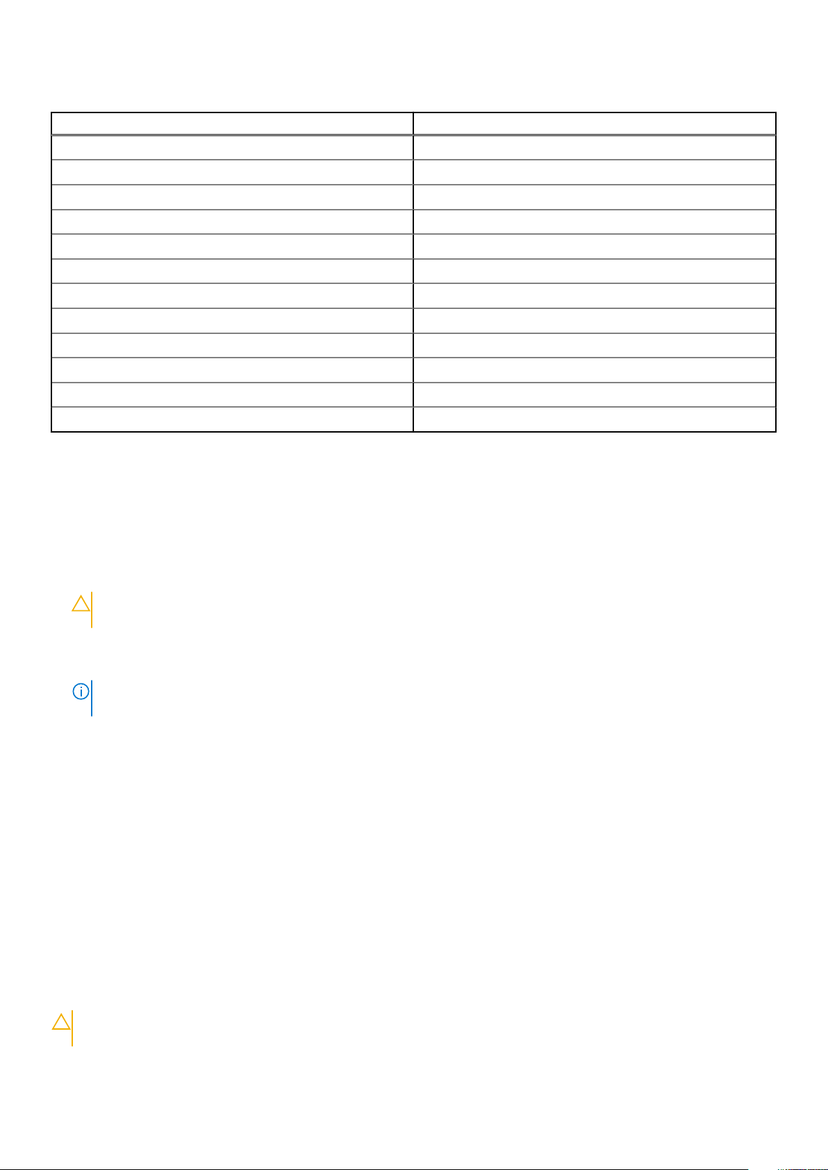
Table 1. Hot key combination (continued)
Fn key combination Precision 7510
Fn+ F1 Speaker Mute
Fn+ F2 Volume Down
Fn+ F3 Volume Up
Fn+ F4 Rewind
Fn+ F5 Play/Pause
Fn+ F6 Forward
Fn+ F8 Display Toggle (Win + P)
Fn+ F9 Search
Fn+ F10 Increase Keyboard Back light Brightness
Fn+ F11 Panel Brightness Down
Fn+ F12 Panel Brightness Up
Fn+ PrtScr Wireless
Before working inside your computer
To avoid damaging your computer, perform the following steps before you begin working inside the computer.
1. Ensure that you follow the Safety instructions.
2. Ensure that your work surface is flat and clean to prevent the computer cover from being scratched.
3. Turn off your computer.
4. Disconnect all the network cables from the computer.
CAUTION:
the network device.
To disconnect a network cable, first unplug the cable from your computer and then unplug the cable from
5. Disconnect your computer and all attached devices from the electrical outlets.
6. Press and hold the power button while the computer is unplugged to ground the system board.
NOTE:
To avoid electrostatic discharge, ground yourself by using a wrist grounding strap or by periodically touching
an unpainted metal surface at the same time as touching a connector on the back of the computer.
Recommended tools
The procedures in this document require the following tools:
• Phillips #0 screwdriver
• Phillips #1 screwdriver
• Small plastic scribe
Turning off your computer
After working inside your computer
After you complete any replacement procedure, ensure that you connect any external devices, cards, and cables before turning on your
computer.
CAUTION:
batteries designed for other Dell computers.
To avoid damage to the computer, use only the battery designed for this particular Dell computer. Do not use
6 Working on your computer

1. Connect any external devices, such as a port replicator or media base, and replace any cards, such as an ExpressCard.
2. Connect any telephone or network cables to your computer.
CAUTION: To connect a network cable, first plug the cable into the network device and then plug it into the
computer.
3. Connect your computer and all attached devices to their electrical outlets.
4. Turn on your computer.
Working on your computer 7

Disassembly and reassembly
Topics:
• System overview
• Removing the Secure Digital (SD) card
• Installing the SD card
• Removing the battery cover
• Installing the battery cover
• Lithium-ion battery precautions
• Removing the battery
• Installing the battery
• Removing the base cover
• Installing the base cover
• Removing the hard drive
• Installing the hard drive
• Removing the Subscriber Identification Module (SIM) card
• Installing the Subscriber Identification Module (SIM) card
• Removing the keyboard
• Installing the keyboard
• Removing the secondary memory
• Installing the secondary memory
• Removing the primary memory
• Installing the primary memory
• Removing Wireless Wide Area Network (WWAN) card (Optional)
• Installing the WWAN card (Optional)
• Removing the Wireless Local Area Network (WLAN) card
• Installing the WLAN Card
• Removing the M.2 Solid State Drive (SSD)
• Installing the M.2 SSD
• Removing the coin cell battery
• Installing the coin cell battery
• Removing the hard drive cable
• Installing the hard drive cable
• Removing the power connector port
• Installing the power connector port
• Removing the palmrest
• Installing the palmrest
• Removing the speakers
• Installing the speakers
• Removing the Input/Output (I/O) board left
• Installing the I/O board left
• Removing the Input/Output (I/O) board right
• Installing the I/O board right
• Removing the heat sink assembly
• Installing the heat sink assembly
• Removing the video card
• Installing the video card
• Removing the display assembly
• Installing the display assembly
• Removing the display bezel
• Installing the display bezel
2
8 Disassembly and reassembly
• Removing the display panel
• Installing the display panel
• Removing the camera
• Installing the camera
• Removing the system board
• Installing the system board
System overview
Figure 1. Front view
Figure 2. Back view
1.
Network connector 2. Microphone
3. Camera (optional) 4. Camera-status light (optional)
5. Power connector 6. Power button
7. Security-cable slot 8. USB 3.0 connector
9. Headset connector 10. Memory card reader
11. Fingerprint reader 12. Battery-status light
13. Hard-drive activity light 14. Power-status light
15. Speakers 16. Touchpad
Disassembly and reassembly 9
17. Contactless smartcard reader (optional) 18. Smartcard reader (optional)
19. USB 3.0 connector 20. Mini DisplayPort connector
21. HDMI connector 22. USB-C connector
23. Docking connector 24. Service-tag label
25. Door and battery release latch
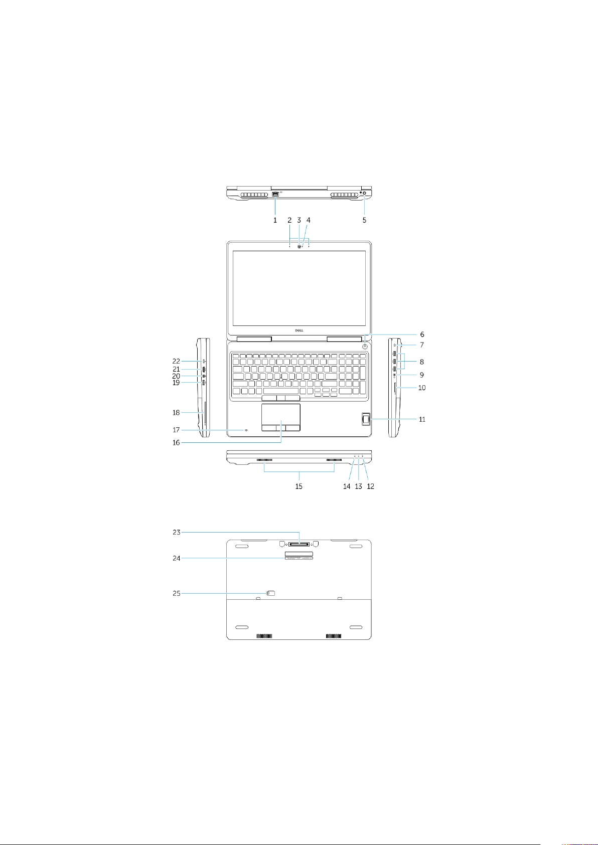
Connecting to a docking station
NOTE: Computers requiring more than 130 W power input must also be connected to their own power adapter for
charging and operating at full performance.
Removing the Secure Digital (SD) card
1. Follow the procedure in Before working inside your computer.
2. Press in on the SD card to release it from the computer. Slide the SD card out of the computer.
Installing the SD card
1. Push in the SD card into its slot until it clicks into place.
2. Follow the procedure in After working inside your computer
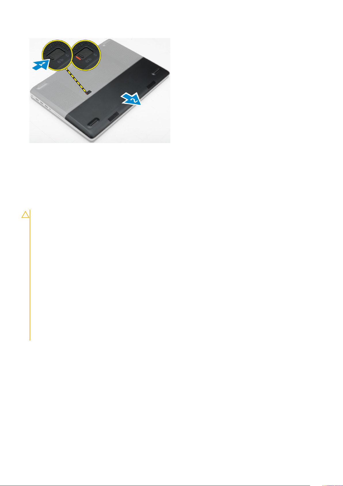
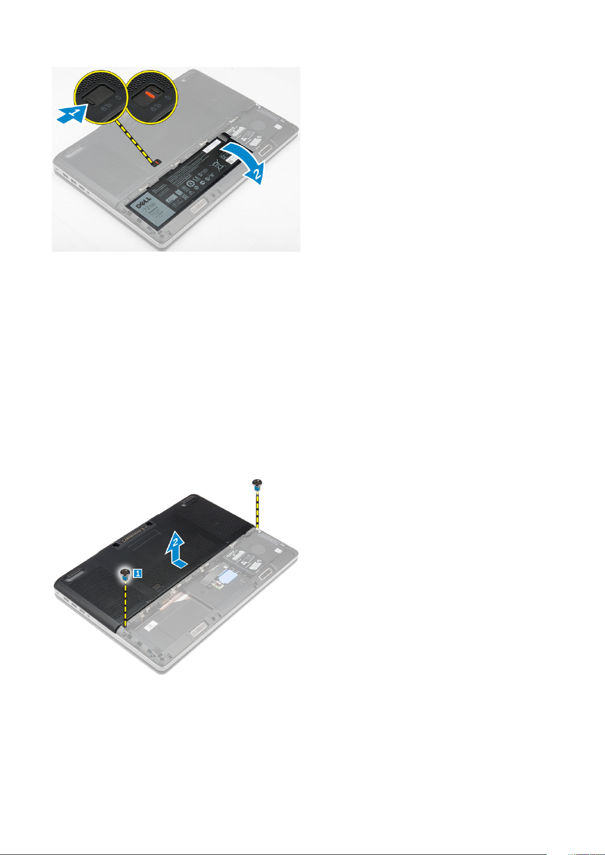
Removing the battery cover
1. Follow the procedure in Before working inside your computer.
2. Perform the following steps as shown in the illustration:
a. Slide the release latch to unlock the battery cover [1].
b. Slide and lift the battery cover to remove it from the computer [2].
10
Disassembly and reassembly
Installing the battery cover
1. Slide the battery cover into its slot until it clicks into place.
2. Follow the procedure in After working inside your computer.
Lithium-ion battery precautions
CAUTION:
• Exercise caution when handling Lithium-ion batteries.
• Discharge the battery completely before removing it. Disconnect the AC power adapter from the system and operate
the computer solely on battery power—the battery is fully discharged when the computer no longer turns on when
the power button is pressed.
• Do not crush, drop, mutilate, or penetrate the battery with foreign objects.
• Do not expose the battery to high temperatures, or disassemble battery packs and cells.
• Do not apply pressure to the surface of the battery.
• Do not bend the battery.
• Do not use tools of any kind to pry on or against the battery.
• Ensure any screws during the servicing of this product are not lost or misplaced, to prevent accidental puncture or
damage to the battery and other system components.
• If the battery gets stuck inside your computer as a result of swelling, do not try to release it as puncturing, bending,
or crushing a lithium-ion battery can be dangerous. In such an instance, contact Dell technical support for
assistance. See www.dell.com/contactdell.
• Always purchase genuine batteries from www.dell.com or authorized Dell partners and resellers.
Removing the battery
1. Follow the procedure in Before working inside your computer.
2. Remove the battery cover.
3. Perform the following steps as shown in the illustration:
a. Slide the release latch to unlock the battery [1].
b. Lift and remove the battery from the computer [2].
Disassembly and reassembly
11
Installing the battery
1. Slide the battery into its slot until it clicks into place.
2. Install the battery cover.
3. Follow the procedure in After working inside your computer
Removing the base cover
1. Follow the procedure in Before working inside your computer.
2. Remove the:
a. battery cover
b. battery
3. Perform the following steps as shown in the illustration:
a. Remove the screws that secure the base cover to the computer [1].
b. Slide and lift the base cover away from the computer [2].
Installing the base cover
1. Slide the base cover to align with the screw holes on the computer.
2. Tighten the screws to secure the base cover to the computer.
3. Install the:
a. battery
12
Disassembly and reassembly
b. battery cover
4. Follow the procedure in After working inside your computer.
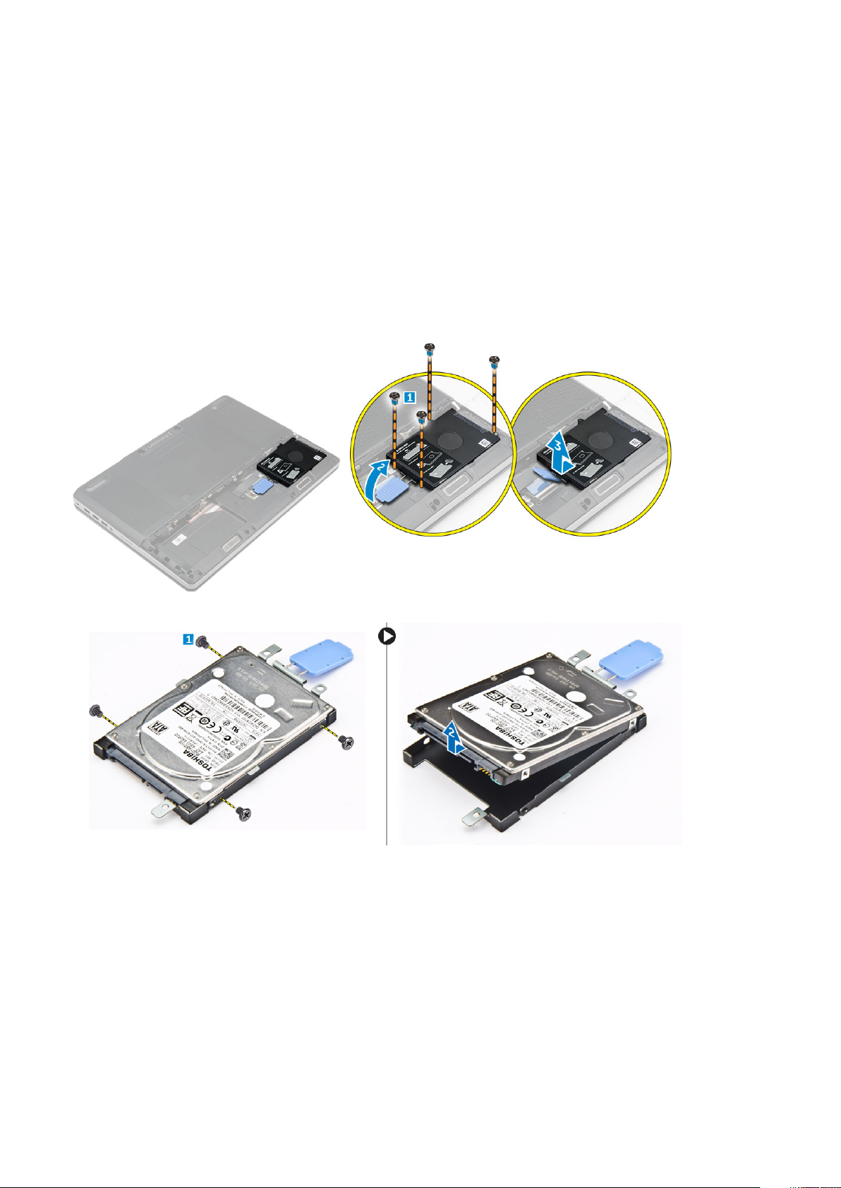
Removing the hard drive
1. Follow the procedure in Before working inside your computer.
2. Remove the:
a. battery cover
b. battery
3. Perform the following steps as shown in the illustration:
a. Remove the screws that secure the hard drive to the computer [1].
b. Pull the hard-drive latch to the unlock position [2].
c. Slide and lift the hard drive from the computer [3].
4. Remove the screws that secure the hard drive to the hard drive bracket [1]. Lift the hard drive from the bracket [2].
Installing the hard drive
1. Tighten the screws to secure the hard drive to the hard-drive bracket.
2. Insert the hard drive into its slot in the computer.
3. Tighten the screws to secure the hard drive to the computer.
4. Install the:
a. battery
b. battery cover
5. Follow the procedure in After working inside your computer
Disassembly and reassembly
13
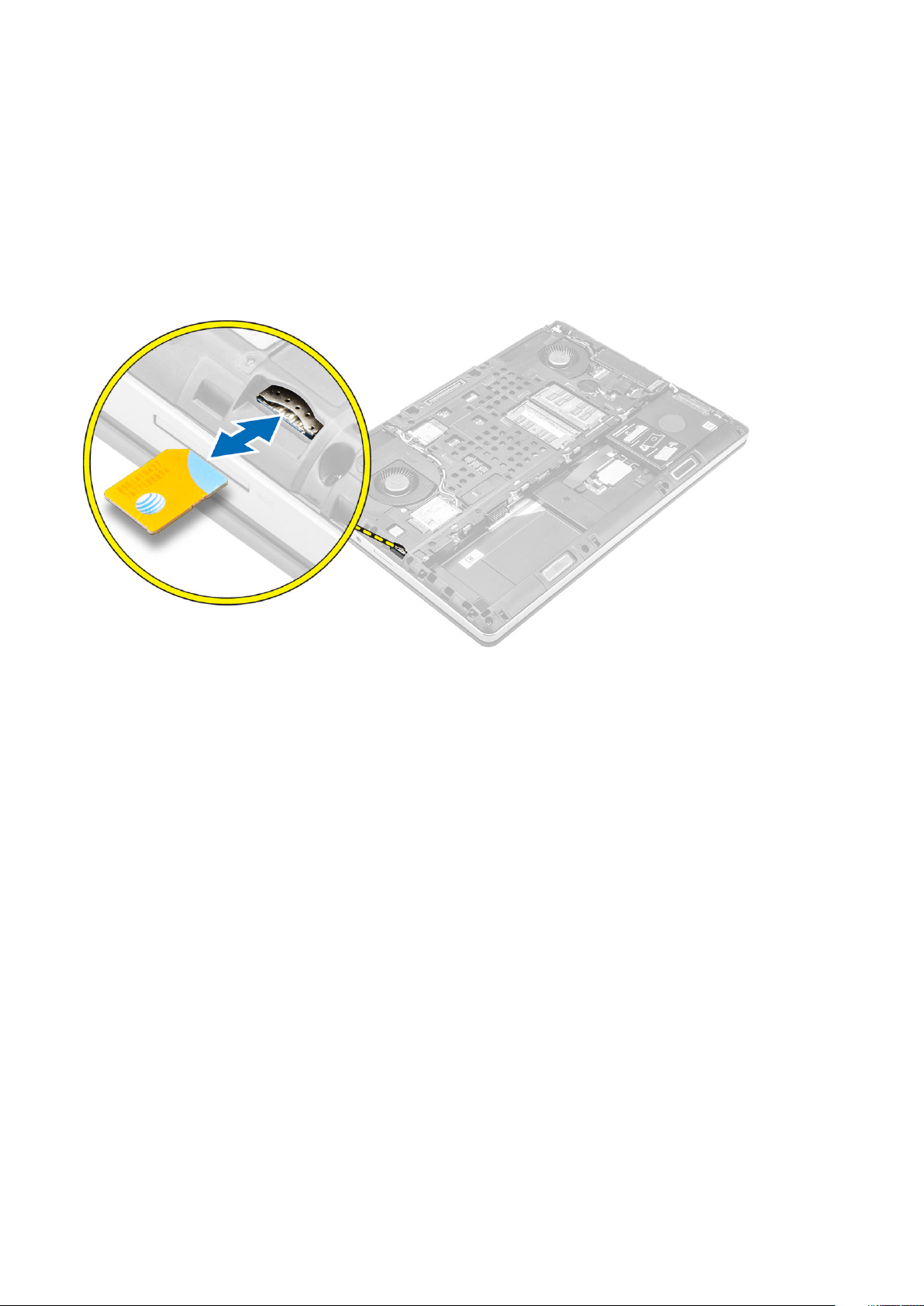
Removing the Subscriber Identification Module (SIM) card
1. Follow the procedure in Before working inside your computer.
2. Remove the:
a. battery cover
b. battery
c. base cover
3. Press the sim card and remove it from the sim card slot.
Installing the Subscriber Identification Module (SIM) card
1. Slide the SIM card in its slot.
2. Press the SIM card to the SIM card slot until it clicks in.
3. Install the:
a. base cover
b. battery
c. battery cover
4. Follow the procedure in After working inside your computer.
Removing the keyboard
1. Follow the procedures in Before working inside your computer.
2. Remove the:
a. battery cover
b. battery
c. hard drive
3. Peel the tape to access the cable [1]. Lift the tab and disconnect the keyboard cables from the fingerprint board [2, 3].
14
Disassembly and reassembly

4. Perform the following steps as shown in the illustration:
a. Pry the keyboard trim starting from bottom and work along the top edge and remove it away from the computer [1, 2, 3].
b. Remove the screws that secure the keyboard to the computer [4].
c. Lift the front side and slide the keyboard to remove it away from the computer [5].
Installing the keyboard
1. Press and align the keyboard to its compartment.
2. Tighten the screws to secure the keyboard to the computer.
3. Slide the keyboard trim from the front and align it to its position on the computer. Ensure that the keyboard trim clicks into its place
4. Connect the keyboard-data cable to the fingerprint board.
NOTE: Ensure that you fold the keyboard-data cable in perfect alignment.
5. Affix the tape on the keyboard data cables.
6. Install the:
a. hard drive
b. battery
c. battery cover
7. Follow the procedure in After working inside your computer.
Removing the secondary memory
1. Follow the procedure in Before working inside your computer.
2. Remove the:
a. battery cover
b. battery
c. hard drive
Disassembly and reassembly
15
d. keyboard
3. Perform the following steps as shown in the illustration:
a. Remove the screw that secures the memory shield to the computer [1].
b. Lift and remove the memory shield from the computer [2].
c. Pry the retention clips away from the memory module until it pops up [3].
d. Lift the memory module and remove it from the computer [4].
Installing the secondary memory
1. Insert the secondary memory into the memory socket.
2. Press the clips to secure the memory module to the system board.
3. Place the memory shield in its original position on the computer and tighten the screw to secure it to the computer.
4. Install the:
a. keyboard
b. hard drive
c. battery
d. battery cover
5. Follow the procedure in After working inside your computer.
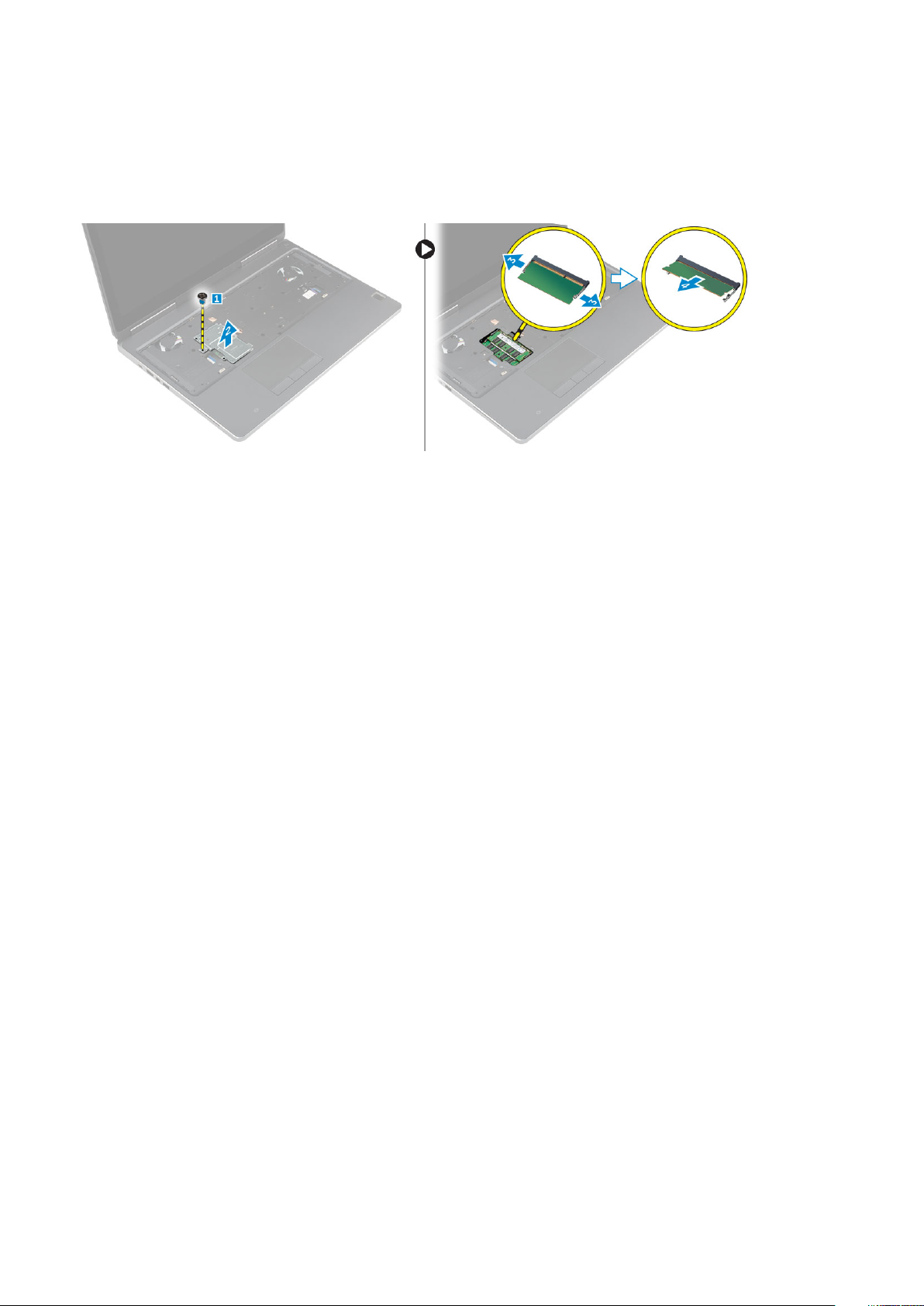
Removing the primary memory
1. Follow the procedure in Before working inside your computer.
2. Remove the:
a. battery cover
b. battery
c. base cover
3. Perform the following steps to remove the primary memory:
a. Pry the retention clips away from the primary memory until it pops up.
b. Lift the primary memory and remove it from the computer.
16
Disassembly and reassembly
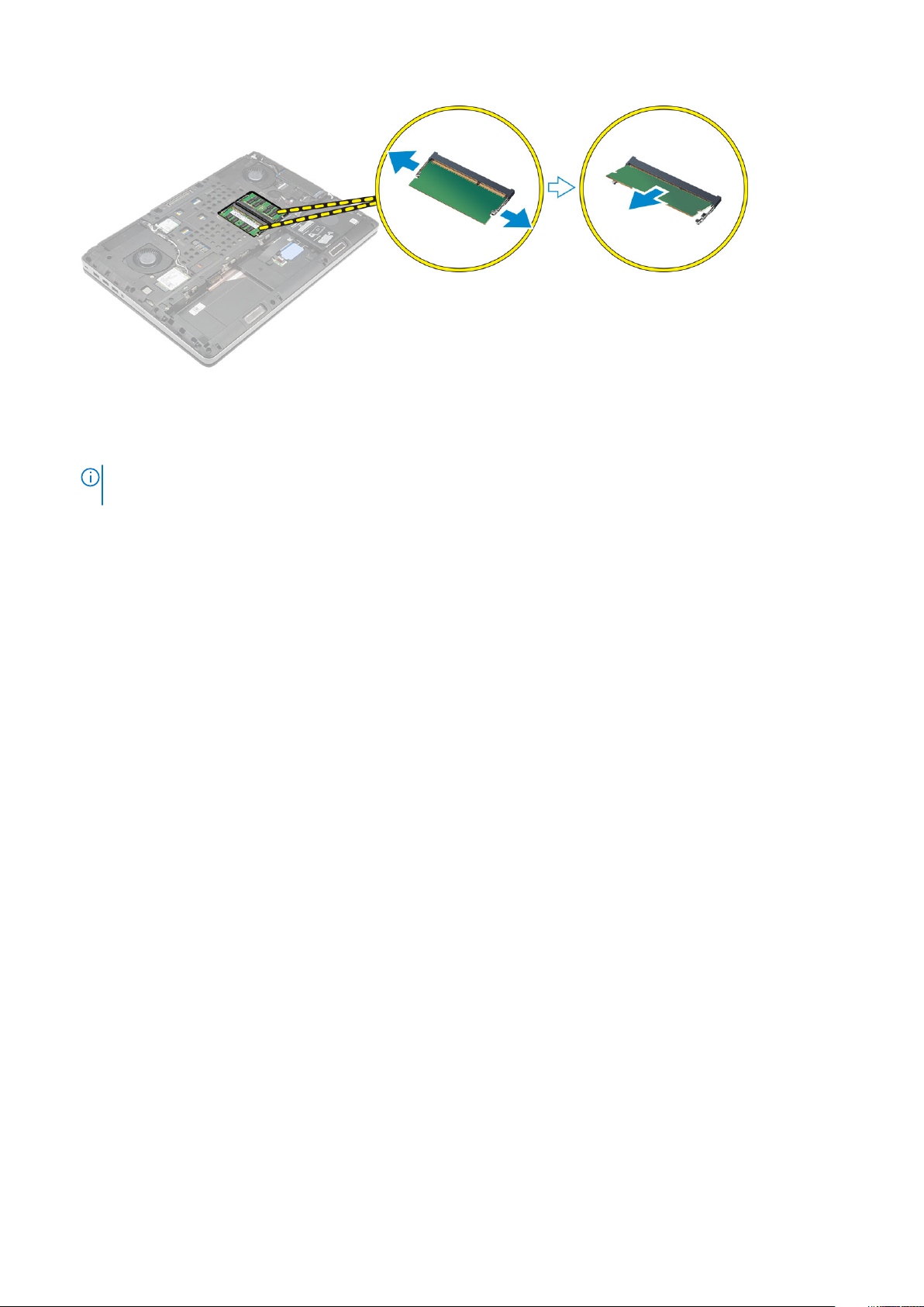
Installing the primary memory
1. Insert the primary memory into the memory socket.
NOTE: Install either two or four memory modules in the memory module slots to ensure optimum system
performance. Installing one or three memory modules lead to system performance issues.
2. Press the clips to secure the primary memory to the system board.
3. Install the:
a. base cover
b. battery
c. battery cover
4. Follow the procedure in After working inside your computer.
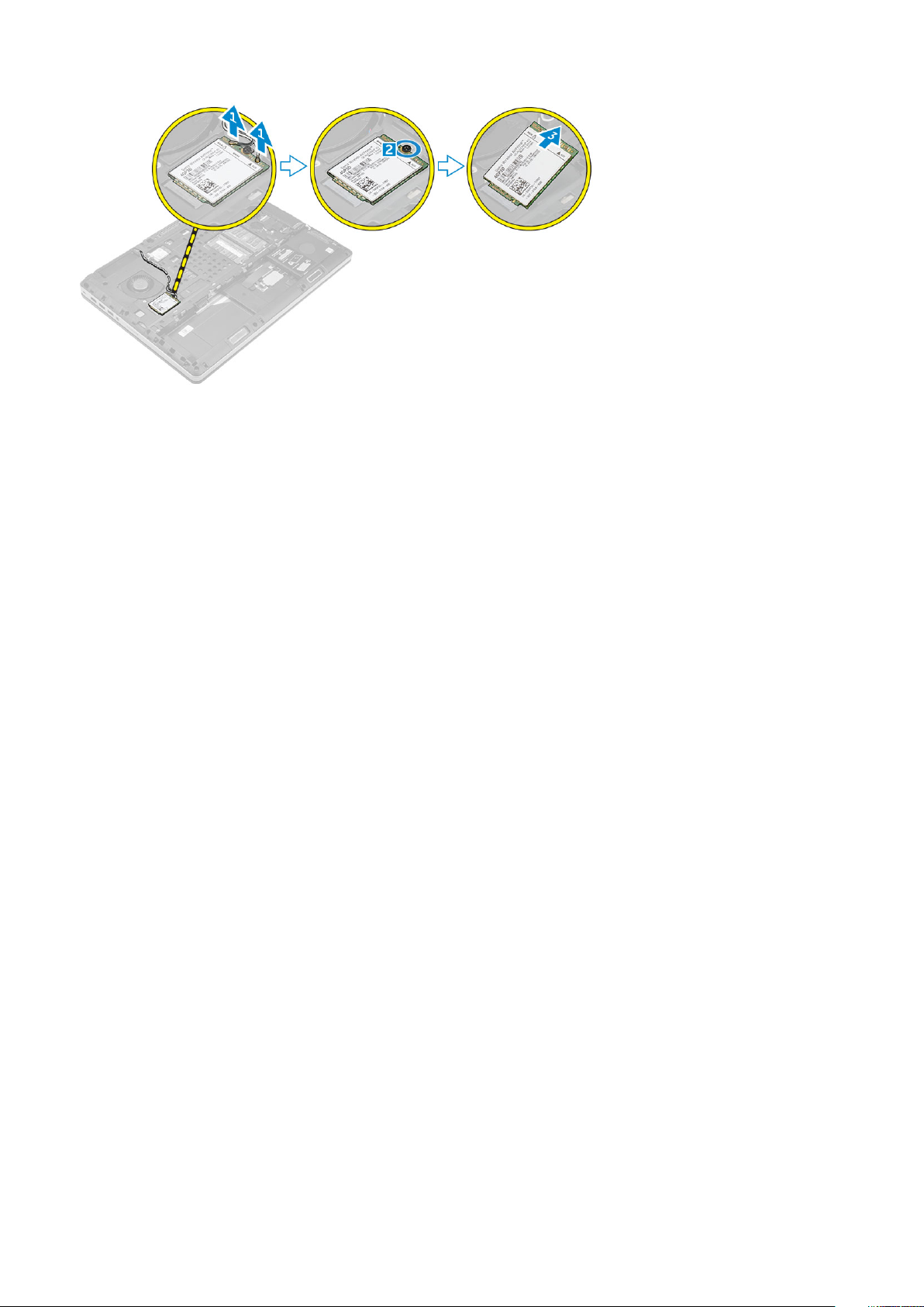
Removing Wireless Wide Area Network (WWAN) card (Optional)
1. Follow the procedure in Before working inside your computer.
2. Remove the:
a. battery cover
b. battery
c. base cover
3. Please perform the following steps to remove the WWAN card:
a. Disconnect and remove the antenna cables connected to the WWAN card [1].
b. Remove the screw that secures the WWAN card to the computer [2].
c. Remove the WWAN card from the computer [3].
Disassembly and reassembly
17
Installing the WWAN card (Optional)
1. Slide the WWAN card to the WWAN card slot.
2. Tighten the screw to secure the WWAN card to the computer.
3. Route the antenna cables through the routing channels and connect them to the WWAN card.
4. Install the:
a. base cover
b. battery
c. battery cover
5. Follow the procedure in After working inside your computer
Removing the Wireless Local Area Network (WLAN) card
1. Follow the procedure in Before working inside your computer.
2. Remove the:
a. battery cover
b. battery
c. base cover
3. Perform the following steps to remove the WLAN card from the computer:
a. Remove the screw that secures the WLAN card to the computer.
b. Remove the shield that secure the antenna cables.
c. Disconnect and un-route the antenna cables connected to the WLAN card and remove the WLAN card from the computer.
18
Disassembly and reassembly
 Loading...