

Page 1

'HOO
2SWL3OH[
*;L/RZ3URILOH6\VWHPV
5()(5(1&($1',167$//$7,21*8,'(
®
0RGHO'&6
Page 2

Page 3

'HOO
2SWL3OH[
*;L/RZ3URILOH6\VWHPV
5()(5(1&($1',167$//$7,21*8,'(
®
Page 4

Information in this document is subject to change without notice.
1991–1996 Dell Computer Corpo ra tion. All rights reserved.
Reproduction in a ny m an n e r w hat soever without the written perm i ssion of Dell Computer Corporation is strictly forbidde n.
Trademarks used in this te xt: Dell, OptiPlex, and the DELL logo are registered trademarks and DellWare is a registered service mark of Dell
Computer Corporation; Intel and Pentium are regi ste r ed trademarks of Intel Corporation; Microsoft, MS-DOS, Windows, and Windows N T are
registered trad emarks and Windows for Workgroups is a trademark of Microsoft Corporation; IBM and OS/2 are regist ere d trademarks of International Business Machines Corporation; Novell and NetWare are registered trademar ks of No vell, In c.; 3Com is a registered trademark of 3Com
Corporation; VESA is a registered trademark of Video Electronics Standards Association; and UNIX is a registered trademark of UNIX System
Laboratories, Inc. , a whol ly owned subsidiary of Novell, In c. As an Energy Star Partner, Del l Computer Corporation ha s det er mi ned that this
product meets the Energy Star guideline s for energy efficiency.
Other trademarks and t rade names may be used in this document to refer to either the ent itie s claiming the marks and nam es or th ei r products.
Dell Computer Corporation disclaims any pro prietary interest in trademarks and trade names other th an i ts own.
September 1996 P/N 50557
Page 5

Safety Instructions
When Using Your Computer System
As you use your computer system, observe the fo llow ing
safety guidelines:
•
To help avoid damaging your computer, be sure the
voltage selection switch on the power supply is set to
match the alternating current (AC) power available
at your location:
— 115 volts (V)/60 hertz (Hz) in most of North and
South America and some Far Eastern countries
such as Japan, South Korea, and Taiwan
— 230 V/50 Hz in most of Europe, the Middle
East, and the Far East
Also be sure your monitor and attached peripherals
are electrically rated to operate with the AC power
available in your location.
•
To help prevent electric shock, plug the computer
and peripheral power cables into properly grounded
power source s. These cables are equipped with
3-prong plugs to ensure proper grounding. Do not
use adapter plugs or remove the grounding prong
from a cable. If you must use an extension cable , use
a 3-wire cable with properly grounded plugs.
•
To help protect your computer system from sudden,
transient increases and decreases in electrical power,
use a surge suppressor, line conditioner, or uninterruptible power supply.
•
Be sure nothing rests on your computer system’s
cables and that the cables are not located where they
can be stepped on or tripped over.
•
Do not spill food or liquids on your computer. If the
computer gets wet, consult your Diagnostics and
Troubleshooting Guide.
•
Do not push any objects into the openings of your
computer. Doing so can cause fire or electric shock
by shorting out interior components.
•
Keep your computer away from radiators and heat
sources. Also, do not block cooling vents. Avoid
placing loose papers underneath yo ur computer; do
not place your computer in a closed-in wall unit or
on a bed, sofa , or rug.
Ergonomic Computing Habits
WARNING: Improper or prolonged keyboard use
may result in injury.
For maximum comfort and efficiency, observe the following ergonomic guidelines when setting up and using
your computer system:
•
Position your system so that the monitor and keyboard are directly in front of you as you work.
Special shelves are available (from Dell and other
sources) to help you correctly po sition your
keyboard.
•
Set the monitor at a comfortable viewing distance
(usually 510 to 610 millimeters [20 to 24 inches]
from your e yes).
•
Make sure the monitor screen is at eye level or
slightly lower when you are sitting in front of the
monitor.
•
Adjust the tilt of the monitor, its contrast and brigh tness settings, and the lighting around you (such as
overhead lights, desk lamps, and the curtains or
blinds on nearby windows) to minimize reflections
and glare on the monitor screen.
•
Use a chair that provides good lower back support.
v
Page 6
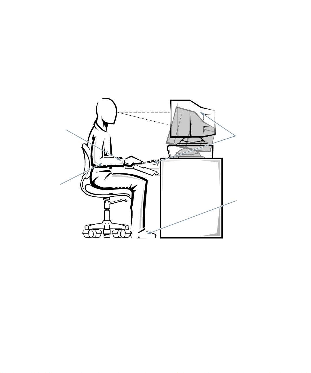
•
Keep your forearms horizontal with your wrists in a
neutral, comfortable position while using the keyboard or mouse.
•
Always leave space to rest your hands while using
the keyboard or mouse.
•
Let your upper arms hang naturally at your sides.
•
Sit erect, with your feet resting o n the f lo or and y our
thighs level.
wrists relaxed and flat
arms at desk level
•
When sitting, make sure the weight of your legs is on
your feet and not on the front of your chair seat.
Adjust your chair’s height or use a footrest, if necessary, to maintain proper posture.
•
Vary your work activities. Try to organize your work
so that you do not have to type for extended periods
of time without stopping. When you stop typing, try
to do things that use both hands.
monitor screen at or below eye level
monitor and keyboard
positioned directly
in front of user
feet flat on the floor
vi
Page 7

When Working Inside Your Computer
Before you remove the computer cover, perform the following steps in the sequence indicated:
1. Turn off your computer and any peripherals.
2. Disconnect your computer and peripherals from
their power sources. Also, disconnect any
telephone or telecommunication lines from the
computer.
Doing so reduces the potential for personal injury or
shock.
3. Touch an unpainted metal surface on the chassis,
such as the power supply at the back of the
computer, before touching anything inside your
computer.
While you work, periodically touch an unpainted
metal surface on the computer chassis to dissipate
any static electricity that might harm internal
components.
In addition, take note of these safety guidelines when
appropriate:
Do not attempt to service the computer system your-
•
self, except as explained in this guide and elsewhere
in Dell documentation. Always follow installation
and servicing instructions closely.
When removing a component from the system board
•
or disconnecting a peripheral device from the computer, wait 5 seconds after turning off the system
before removing the component or disc onnecting the
device to avoid possible damage to the system board.
When you disconnect a cable, pull on its connector
•
or on its strain-relief loop, not on the cable itself.
Some cables have a connector with locking tabs; if
you are disconnecting this type of cable, press in on
the locking tabs before disconnecting the cable. As
you pull connectors apart, keep them evenly aligned
to avoid bending any connector pins. Also, before
you connect a cable, make sure both connectors are
correctly oriented and aligned.
Handle components and cards with care. Don’t tou ch
•
the components or contacts on a card. Hold a card by
its edges or by its metal mounting bracket. Hold a
component such as a microprocessor chip by its
edges, not by its pins.
Protecting Against Electrostatic Discharge
Static electricity can harm delicate components inside
your computer. To prevent static damage, discharge static
electricity from your body before you touch any of your
computer’s electronic components, such as the microprocessor. You can do so by t ouchi ng an u npain ted metal
surface on the computer chassis.
As you continue to work inside the computer, periodically touch an unpainted metal surface to remove any
static charge your body may have accumulated.
In addition to the preceding precautions, you can also
take the following steps to prevent damage from electrostatic discharge (ESD):
When unpacking a static-sensitive component from
•
its shipping carton, do not remove the component’s
antistatic packing material until you are ready to
install the component in your computer. Just before
unwrapping the antistatic packaging, be sure to discharge static electricity from your body.
When transporting a sensitive component, first place
•
it in an antistatic container or packaging.
Handle all sensitive components in a static-safe area.
•
If possible, use antistatic floor pads and workbench
pads.
The following caution appears throughout this docu ment
to remind you of these precautions:
CAUTION: See “Protecting Against Electrostatic
Discharge” in the safety instructions at the front of
this guide.
vii
Page 8

viii
Page 9

Preface
A
bout This Guide
This guide is intended for anyone who uses a Dell OptiPlex GXi low-profile computer system. It can be used by
both first-time and experienced computer users who want
to learn about the features and operation of the systems or
who want to upgrade their computers. The chapters and
appendixes are summarized as follows:
•
Everyone should read Chapter 1, “Introduction,” for
an overview of the system features, instructions on
how to access the online System User’s Guide, and
information on where to get help if you need it.
•
Everyone should read the first several sections of
Chapter 2, “Using the System Setup Program,” to
familiarize themselves with this important program.
Only users who want to mak e co nfigu rat ion changes
to their system or who want to use the password features need to read the rest of Chapter 2.
•
Users who add or remove an Industry-Standard
Architecture (ISA) expansion card should read
Chapter 3, “Using the ISA Configuration Utility.”
•
Users who want to change the defaul t configuration
of the system’s integrated video and audio controllers or who want to connect their system to a
network should read Chapter 4, “Using Integrated
Devices.” This chapter describes the configuration
software provided for the integrated video and audio
controllers and provides information on connecting
the system to a network, configuring the network
interface controller (NIC), and installing drivers for
the NIC.
•
Chapter 5, “Working Inside Your Computer,” Chapter 6, “Installing System Board Options,” and
Chapter 7, “Installing Drives,” are intended for users
who want to install or remove options inside the
computer, such as dual in-line memory modules
(DIMMs), expansion cards, or drives.
•
Appendix A, “Technical Specifications,” is intended
primarily as reference material for users interested in
learning more about the details of the system.
•
Appendix B, “ISA Configuration Utility Messages,”
describes error messages generated by the ISA Configuration Utility (ICU), possible causes, and
corrective actions.
•
Appendix C, “Regulatory Notices,” is for users who
are interested in which regulatory agencies have
tested and approved the Dell OptiPlex GXi lowprofile systems.
•
Appendix D, “Warranties an d Return Policy,”
describes the warranty for your Dell system and the
“Total Satisfaction” return policy.
W
arranty and Return Policy
Information
Dell Computer Corporation (“Dell”) manufactures its
hardware products from parts and components that are
new or equivalent to new in accordance with industrystandard practices. For information about the Dell
warranty for your system, see Appendix D, “Warranties
and Return Policy.”
ix
Page 10

O
ther Documents You May Need
Besides this Reference and Installation Guide, the following documentation is included with your system:
•
The Getting Started sheet provides step-by-step
instructions for setting up your computer sys tem.
•
The Windows-based online System User’s Guide
contains important i nformati on abou t you r comput er
system. This document includes descriptions of
system features, instructions on installing and configuring drivers and utilities, information on the
System Setup program and ISA Configuration Utility, and instructions for attaching devices to the
connectors on your computer’s back panel.
•
The Frequently Asked Questions cards provide
detailed answers to questions that are often asked by
Dell computer users. Be sure to read these cards
before calling Dell for technical assistance.
•
The Diagnostics and Troubleshooting Guide
includes troubleshooting procedures and instructions
for using the diskette-based diagnostics to test yo ur
computer system.
You may also have one or more of the following
documents.
NOTE: Documentation updates are sometimes included
with your system to describe changes to your system or
software. Always read these updates
any other documentation because the updates often contain the latest information.
•
Operating system documentation is included if you
ordered your operating system software from Dell.
This documentation describes how to install (if necessary), configure, and use your operating system
software.
•
Documentation is included with any options you
purchase separately from your system. This documentation includes information that you need to
configure and install these options in your Dell computer. Installatio n instructions for the options are
included in this Reference and Installation Guide.
before
consulting
•
Technical information files—sometimes called
“readme” files—may be installed on your hard-disk
drive to provide last-minute updates about technical
changes to your system or advanced technical
reference material intended for experienced users or
technicians.
N
otational Conventions
The following subsections list notational conventions
used in this document.
Warnings, Cautions, and Notes
Throughout this guide, there may be blocks of text
printed in bold type within boxes or in italic type. These
blocks are warnings, cautions, and notes, and they are
used as follows:
WARNING: A WARNING indicates the potential
for bodily harm and tells you how to avoid the
problem.
CAUTION: A CAUTION indicates either potential damage to hard ware or loss of data and tells
you how to avoid the problem.
NOTE: A NOTE indicates impo rtant information that
helps you make better use of your computer system.
Typographical Conventions
The following list defines (where appropriate) and illustrates typographical conventions used as visual cues for
specific elements of text throughout this document:
•
Keycaps, the labeling that appears on the keys on a
keyboard, are presented in upper case and enclosed in
angle brackets.
Example: <
ENTER
>
x
Page 11

•
Key combinations are series of keys to be pressed
simultaneously (unless otherwise indicated) to perform a single function.
Example: <
•
All items on a menu screen are presented in the HEL-
VETICA
Example:
•
Commands presented in lowercase bold are fo r ref erence purposes only and are not intended to be typed
at that particular point in the discussion.
Example: “Use the format command to. . . .”
In contrast, commands presented in the Courier font
are intended to be typed as part of an instruction.
Example: “Type
in drive A.”
•
Filenames and directory names are presented in
lowercase bold.
Examples: autoexec.bat and c:\windows
•
Syntax lines consist of a command and all its
possible parameters. Commands are displayed in
lowercase bold; variable parameters (those for which
you substitute a value) are displayed in lowercase
italics; constant parameters are displayed in lowercase bold. The brackets indicate items that are
optional.
Example: del [drive:] [path]filename [/p]
CTRL><ALT><ENTER
font and in uppercase bold.
SETUP PASSWORD category
format a:
>
to format the diskette
•
Command lines consist of a command and may
include one or more of the command’s possible
parameters. Command lines are presented in the
Courier
Example:
•
Screen text is text that appears on the screen of your
monitor or display. It can be a system message, for
example, or it can be text that you are instructed to
type as part of a command (referred to as a comman d
line). Screen text is presented in the
Example: “Type
<
ENTER
Example: The following message appears on your
screen:
No boot device available
•
Variables are p laceholders fo r which you substitute a
value. They are presented in italics.
Example: DIMM_x (where x represents the DIMM
socket designation)
font.
del c:\myfile.d oc
md c:\dos
>.”
Courier
, and then press
font.
xi
Page 12

xii
Page 13

Contents
Chapter 1
Introduction . . . . . . . . . . . . . . . . . . . . . . . . . . . . . . . . . . . . . . . . . . . 1-1
System Features. . . . . . . . . . . . . . . . . . . . . . . . . . . . . . . . . . . . . . . . . . . . . . . . . . . . . . 1-1
Using the Optional Floor Stand. . . . . . . . . . . . . . . . . . . . . . . . . . . . . . . . . . . . . . . . . . 1-3
Security Cable Slot and Padlock Ring . . . . . . . . . . . . . . . . . . . . . . . . . . . . . . . . . . . . 1-4
Energy Star Comp lia nce . . . . . . . . . . . . . . . . . . . . . . . . . . . . . . . . . . . . . . . . . . . . . . . 1-4
Important Note to Windows 95 Users. . . . . . . . . . . . . . . . . . . . . . . . . . . . . . . . . . . . . 1-5
Accessing Online Documentation. . . . . . . . . . . . . . . . . . . . . . . . . . . . . . . . . . . . . . . .1-5
Getting Help . . . . . . . . . . . . . . . . . . . . . . . . . . . . . . . . . . . . . . . . . . . . . . . . . . . . . . . . 1-6
Chapter 2
Using the System Setup Program . . . . . . . . . . . . . . . . . . . . . . . . . 2-1
Entering the System Setup Program . . . . . . . . . . . . . . . . . . . . . . . . . . . . . . . . . . . . . . 2-1
System Setup Screens . . . . . . . . . . . . . . . . . . . . . . . . . . . . . . . . . . . . . . . . . . . . . . . . . 2-2
Using the System Setup Program . . . . . . . . . . . . . . . . . . . . . . . . . . . . . . . . . . . . . . . . 2-2
System Setup Categories. . . . . . . . . . . . . . . . . . . . . . . . . . . . . . . . . . . . . . . . . . . . . . . 2-4
Time . . . . . . . . . . . . . . . . . . . . . . . . . . . . . . . . . . . . . . . . . . . . . . . . . . . . . . . . . . . 2-4
Date . . . . . . . . . . . . . . . . . . . . . . . . . . . . . . . . . . . . . . . . . . . . . . . . . . . . . . . . . . . 2-4
Diskette Drive A and Diskette Drive B . . . . . . . . . . . . . . . . . . . . . . . . . . . . . . . . 2-4
Drive A Location . . . . . . . . . . . . . . . . . . . . . . . . . . . . . . . . . . . . . . . . . . . . . . . . .2-4
Drives: Primary and Secondary . . . . . . . . . . . . . . . . . . . . . . . . . . . . . . . . . . . . . . 2-4
EIDE Devices . . . . . . . . . . . . . . . . . . . . . . . . . . . . . . . . . . . . . . . . . . . . . . . . 2-5
If You Have a Problem. . . . . . . . . . . . . . . . . . . . . . . . . . . . . . . . . . . . . . . . . 2-5
Base Memory. . . . . . . . . . . . . . . . . . . . . . . . . . . . . . . . . . . . . . . . . . . . . . . . . . . . 2-6
Extended Memory . . . . . . . . . . . . . . . . . . . . . . . . . . . . . . . . . . . . . . . . . . . . . . . . 2-6
Reserved Memory . . . . . . . . . . . . . . . . . . . . . . . . . . . . . . . . . . . . . . . . . . . . . . . . 2-6
CPU Speed. . . . . . . . . . . . . . . . . . . . . . . . . . . . . . . . . . . . . . . . . . . . . . . . . . . . . . 2-6
Num Lock. . . . . . . . . . . . . . . . . . . . . . . . . . . . . . . . . . . . . . . . . . . . . . . . . . . . . . . 2-6
Keyboard Errors . . . . . . . . . . . . . . . . . . . . . . . . . . . . . . . . . . . . . . . . . . . . . . . . . . 2-6
System Password . . . . . . . . . . . . . . . . . . . . . . . . . . . . . . . . . . . . . . . . . . . . . . . . . 2-6
xiii
Page 14

Password Status. . . . . . . . . . . . . . . . . . . . . . . . . . . . . . . . . . . . . . . . . . . . . . . . . . 2-7
Boot Sequence. . . . . . . . . . . . . . . . . . . . . . . . . . . . . . . . . . . . . . . . . . . . . . . . . . . 2-7
Setup Password . . . . . . . . . . . . . . . . . . . . . . . . . . . . . . . . . . . . . . . . . . . . . . . . . . 2-7
Auto Power On . . . . . . . . . . . . . . . . . . . . . . . . . . . . . . . . . . . . . . . . . . . . . . . . . . 2-7
Power Management. . . . . . . . . . . . . . . . . . . . . . . . . . . . . . . . . . . . . . . . . . . . . . . 2-7
Saving Monitor Power. . . . . . . . . . . . . . . . . . . . . . . . . . . . . . . . . . . . . . . . . 2-8
Saving EIDE Hard-Disk Drive Power. . . . . . . . . . . . . . . . . . . . . . . . . . . . . 2-8
Sound. . . . . . . . . . . . . . . . . . . . . . . . . . . . . . . . . . . . . . . . . . . . . . . . . . . . . . . . . . 2-8
NIC . . . . . . . . . . . . . . . . . . . . . . . . . . . . . . . . . . . . . . . . . . . . . . . . . . . . . . . . . . . 2-8
Mouse . . . . . . . . . . . . . . . . . . . . . . . . . . . . . . . . . . . . . . . . . . . . . . . . . . . . . . . . . 2-9
Serial Port . . . . . . . . . . . . . . . . . . . . . . . . . . . . . . . . . . . . . . . . . . . . . . . . . . . . . . 2-9
Parallel Port. . . . . . . . . . . . . . . . . . . . . . . . . . . . . . . . . . . . . . . . . . . . . . . . . . . . . 2-9
Parallel Mode . . . . . . . . . . . . . . . . . . . . . . . . . . . . . . . . . . . . . . . . . . . . . . . . . . . 2-9
Hard Disk . . . . . . . . . . . . . . . . . . . . . . . . . . . . . . . . . . . . . . . . . . . . . . . . . . . . . . 2-9
Diskette . . . . . . . . . . . . . . . . . . . . . . . . . . . . . . . . . . . . . . . . . . . . . . . . . . . . . . . . 2-9
USB. . . . . . . . . . . . . . . . . . . . . . . . . . . . . . . . . . . . . . . . . . . . . . . . . . . . . . . . . . 2-10
Speaker . . . . . . . . . . . . . . . . . . . . . . . . . . . . . . . . . . . . . . . . . . . . . . . . . . . . . . . 2-10
ECC. . . . . . . . . . . . . . . . . . . . . . . . . . . . . . . . . . . . . . . . . . . . . . . . . . . . . . . . . . 2-10
System Data Categories . . . . . . . . . . . . . . . . . . . . . . . . . . . . . . . . . . . . . . . . . . 2-10
Using the System Password Feature. . . . . . . . . . . . . . . . . . . . . . . . . . . . . . . . . . . . . 2-10
Assigning a System Passwor d. . . . . . . . . . . . . . . . . . . . . . . . . . . . . . . . . . . . . . 2-11
Using Your System Password to Secure Your System. . . . . . . . . . . . . . . . . . . 2-11
Deleting or Changing an Existing System Password . . . . . . . . . . . . . . . . . . . . 2-12
Using the Setup Password Feature. . . . . . . . . . . . . . . . . . . . . . . . . . . . . . . . . . . . . . 2-12
Assigning a Setup Password . . . . . . . . . . . . . . . . . . . . . . . . . . . . . . . . . . . . . . . 2-12
Operating With a Setup Password Enabled. . . . . . . . . . . . . . . . . . . . . . . . . . . . 2-13
Deleting or Changing an Existing Se tup Password. . . . . . . . . . . . . . . . . . . . . . 2-13
Disabling a Forgotten Password. . . . . . . . . . . . . . . . . . . . . . . . . . . . . . . . . . . . . . . . 2-13
Responding to Error Messages. . . . . . . . . . . . . . . . . . . . . . . . . . . . . . . . . . . . . . . . . 2-14
Chapter 3
Using the ISA Configuration Utility . . . . . . . . . . . . . . . . . . . . . . . . 3-1
Quick Start . . . . . . . . . . . . . . . . . . . . . . . . . . . . . . . . . . . . . . . . . . . . . . . . . . . . . . . . . 3-1
About the ICU . . . . . . . . . . . . . . . . . . . . . . . . . . . . . . . . . . . . . . . . . . . . . . . . . . . . . . 3-2
ICU Database . . . . . . . . . . . . . . . . . . . . . . . . . . . . . . . . . . . . . . . . . . . . . . . . . . . 3-2
When to Run the ICU. . . . . . . . . . . . . . . . . . . . . . . . . . . . . . . . . . . . . . . . . . . . . . . . . 3-2
Preparing to Use the ICU . . . . . . . . . . . . . . . . . . . . . . . . . . . . . . . . . . . . . . . . . . . . . . 3-3
Backing Up the ICU Diskette . . . . . . . . . . . . . . . . . . . . . . . . . . . . . . . . . . . . . . . 3-3
xiv
Page 15

Starting the ICU. . . . . . . . . . . . . . . . . . . . . . . . . . . . . . . . . . . . . . . . . . . . . . . . . . . . . . 3-3
Accessing Help. . . . . . . . . . . . . . . . . . . . . . . . . . . . . . . . . . . . . . . . . . . . . . . . . . .3-3
Making Selections in the ICU . . . . . . . . . . . . . . . . . . . . . . . . . . . . . . . . . . . . . . . 3-4
Adding a Listed Card . . . . . . . . . . . . . . . . . . . . . . . . . . . . . . . . . . . . . . . . . . . . . . . . . 3-4
Adding an Unlisted Card. . . . . . . . . . . . . . . . . . . . . . . . . . . . . . . . . . . . . . . . . . . . . . . 3-6
Modifying a Car d . . . . . . . . . . . . . . . . . . . . . . . . . . . . . . . . . . . . . . . . . . . . . . . . . . . . 3-7
Removing a Card. . . . . . . . . . . . . . . . . . . . . . . . . . . . . . . . . . . . . . . . . . . . . . . . . . . . .3-8
Viewing Resources . . . . . . . . . . . . . . . . . . . . . . . . . . . . . . . . . . . . . . . . . . . . . . . . . . . 3-9
Saving the System Configuration . . . . . . . . . . . . . . . . . . . . . . . . . . . . . . . . . . . . . . . . 3-9
Exiting From the ICU . . . . . . . . . . . . . . . . . . . . . . . . . . . . . . . . . . . . . . . . . . . . . . . . 3-10
Advanced Features of the ICU . . . . . . . . . . . . . . . . . . . . . . . . . . . . . . . . . . . . . . . . .3-10
Locking and Unlocking Cards . . . . . . . . . . . . . . . . . . . . . . . . . . . . . . . . . . . . . . 3-10
Locking and Unlocking All Resources. . . . . . . . . . . . . . . . . . . . . . . . . . . . 3-10
Locking and Unlocking Configuration Resources . . . . . . . . . . . . . . . . . . . 3-11
Modifying the Configuration Manager . . . . . . . . . . . . . . . . . . . . . . . . . . . . . . . 3-11
Chapter 4
Using Integrated Devices . . . . . . . . . . . . . . . . . . . . . . . . . . . . . . . . 4-1
Video Controller . . . . . . . . . . . . . . . . . . . . . . . . . . . . . . . . . . . . . . . . . . . . . . . . . . . . . 4-1
Audio Controller . . . . . . . . . . . . . . . . . . . . . . . . . . . . . . . . . . . . . . . . . . . . . . . . . . . . . 4-1
NIC . . . . . . . . . . . . . . . . . . . . . . . . . . . . . . . . . . . . . . . . . . . . . . . . . . . . . . . . . . . . . . . 4-1
Connecting to a Network. . . . . . . . . . . . . . . . . . . . . . . . . . . . . . . . . . . . . . . . . . . . . . . 4-3
Network Cable Requirements . . . . . . . . . . . . . . . . . . . . . . . . . . . . . . . . . . . . . . . 4-3
Configuring the NIC . . . . . . . . . . . . . . . . . . . . . . . . . . . . . . . . . . . . . . . . . . . . . . . . . . 4-3
Client Drivers for Novell NetWare Environments. . . . . . . . . . . . . . . . . . . . . . . . 4-3
Microsoft Windows 95 Client Driver. . . . . . . . . . . . . . . . . . . . . . . . . . . . . . 4-3
Microsoft Windows NT 3.5x Client Driver . . . . . . . . . . . . . . . . . . . . . . . . . 4-4
Microsoft Windows for Workgroups Client Driver . . . . . . . . . . . . . . . . . . . 4-4
Microsoft Windows 3.x Client Driver . . . . . . . . . . . . . . . . . . . . . . . . . . . . . 4-5
MS-DOS Client Driver . . . . . . . . . . . . . . . . . . . . . . . . . . . . . . . . . . . . . . . . .4-5
OS/2 Client Driver . . . . . . . . . . . . . . . . . . . . . . . . . . . . . . . . . . . . . . . . . . . . 4-6
Server Drivers for Novell NetWare Environments . . . . . . . . . . . . . . . . . . . . . . . 4-6
Updating NDIS 2.01 Drivers . . . . . . . . . . . . . . . . . . . . . . . . . . . . . . . . . . . . . . . . 4-7
xv
Page 16

Chapter 5
Working Inside Your Computer . . . . . . . . . . . . . . . . . . . . . . . . . . . 5-1
Before You Begin. . . . . . . . . . . . . . . . . . . . . . . . . . . . . . . . . . . . . . . . . . . . . . . . . . . . 5-1
Safety First—For You an d Your Computer . . . . . . . . . . . . . . . . . . . . . . . . . . . . 5-1
Unpacking Your Hardware Option. . . . . . . . . . . . . . . . . . . . . . . . . . . . . . . . . . . 5-2
Removing the Computer Cover . . . . . . . . . . . . . . . . . . . . . . . . . . . . . . . . . . . . . . . . . 5-2
Replacing the Computer Cover . . . . . . . . . . . . . . . . . . . . . . . . . . . . . . . . . . . . . . . . . 5-2
Removing and Replacing the Expansion-Card Cage. . . . . . . . . . . . . . . . . . . . . . . . . 5-3
Removing the Expansion-Card Cage . . . . . . . . . . . . . . . . . . . . . . . . . . . . . . . . . 5-3
Replacing the Expansion-Card Cage. . . . . . . . . . . . . . . . . . . . . . . . . . . . . . . . . . 5-4
Inside Your Computer . . . . . . . . . . . . . . . . . . . . . . . . . . . . . . . . . . . . . . . . . . . . . . . . 5-4
Jumpers . . . . . . . . . . . . . . . . . . . . . . . . . . . . . . . . . . . . . . . . . . . . . . . . . . . . . . . . 5-4
Switches . . . . . . . . . . . . . . . . . . . . . . . . . . . . . . . . . . . . . . . . . . . . . . . . . . . . . . . 5-5
System Board Labels . . . . . . . . . . . . . . . . . . . . . . . . . . . . . . . . . . . . . . . . . . . . . . . . . 5-8
Chapter 6
Installing System Board Options. . . . . . . . . . . . . . . . . . . . . . . . . . 6-1
Expansion Cards. . . . . . . . . . . . . . . . . . . . . . . . . . . . . . . . . . . . . . . . . . . . . . . . . . . . . 6-2
Expansion Slots . . . . . . . . . . . . . . . . . . . . . . . . . . . . . . . . . . . . . . . . . . . . . . . . . . 6-2
Installing an Expansion Card . . . . . . . . . . . . . . . . . . . . . . . . . . . . . . . . . . . . . . . 6-3
Removing an Expansion Card. . . . . . . . . . . . . . . . . . . . . . . . . . . . . . . . . . . . . . . 6-4
Adding Memory. . . . . . . . . . . . . . . . . . . . . . . . . . . . . . . . . . . . . . . . . . . . . . . . . . . . . 6-4
Performing a Memory Upgrade . . . . . . . . . . . . . . . . . . . . . . . . . . . . . . . . . . . . . 6-5
Installing a DIMM . . . . . . . . . . . . . . . . . . . . . . . . . . . . . . . . . . . . . . . . . . . . 6-6
Removing a DIMM . . . . . . . . . . . . . . . . . . . . . . . . . . . . . . . . . . . . . . . . . . . 6-6
Upgrading the Microprocessor. . . . . . . . . . . . . . . . . . . . . . . . . . . . . . . . . . . . . . . . . . 6-6
Replacing the System Battery . . . . . . . . . . . . . . . . . . . . . . . . . . . . . . . . . . . . . . . . . 6-10
Chapter 7
Installing Drives. . . . . . . . . . . . . . . . . . . . . . . . . . . . . . . . . . . . . . . . 7-1
Removing and Replacing Front-Panel Inserts . . . . . . . . . . . . . . . . . . . . . . . . . . . . . . 7-1
Connecting Drives . . . . . . . . . . . . . . . . . . . . . . . . . . . . . . . . . . . . . . . . . . . . . . . . . . . 7-2
Installing a Drive in the 5.25-Inch Drive Bay . . . . . . . . . . . . . . . . . . . . . . . . . . . . . . 7-3
Installing an EIDE Hard-Disk Drive . . . . . . . . . . . . . . . . . . . . . . . . . . . . . . . . . . . . . 7-6
Partitioning and Logically Formatting You r EIDE Hard-Disk Drive. . . . . . . . . 7-8
xvi
Page 17

Installing SCSI Devices. . . . . . . . . . . . . . . . . . . . . . . . . . . . . . . . . . . . . . . . . . . . . . . . 7-9
SCSI Configuration Guidelines . . . . . . . . . . . . . . . . . . . . . . . . . . . . . . . . . . . . . . 7-9
SCSI ID Numbers . . . . . . . . . . . . . . . . . . . . . . . . . . . . . . . . . . . . . . . . . . . . . 7-9
SCSI Cable and SCSI Termination. . . . . . . . . . . . . . . . . . . . . . . . . . . . . . . .7-9
General Procedure for Installing SCSI Devices. . . . . . . . . . . . . . . . . . . . . . . . .7-11
Partitioning and Formatting SCSI Hard-Disk Drives . . . . . . . . . . . . . . . . . . . . 7-12
Appendix A
Technical Specifications. . . . . . . . . . . . . . . . . . . . . . . . . . . . . . . . . A-1
Appendix B
ISA Configuration Utility Messages . . . . . . . . . . . . . . . . . . . . . . . . B-1
ICU Error Messages . . . . . . . . . . . . . . . . . . . . . . . . . . . . . . . . . . . . . . . . . . . . . . . . . .B-1
Configuration Manager Messages. . . . . . . . . . . . . . . . . . . . . . . . . . . . . . . . . . . . . . . .B-6
Appendix C
Regulatory Notices . . . . . . . . . . . . . . . . . . . . . . . . . . . . . . . . . . . . .C-1
FCC Notices (U.S. Only) . . . . . . . . . . . . . . . . . . . . . . . . . . . . . . . . . . . . . . . . . . . . . .C-1
Class A . . . . . . . . . . . . . . . . . . . . . . . . . . . . . . . . . . . . . . . . . . . . . . . . . . . . . . . . .C-1
Class B . . . . . . . . . . . . . . . . . . . . . . . . . . . . . . . . . . . . . . . . . . . . . . . . . . . . . . . . .C-1
IC Notice (Canada Only). . . . . . . . . . . . . . . . . . . . . . . . . . . . . . . . . . . . . . . . . . . . . . .C-2
EN 55022 Compliance (Czech Republic Only) . . . . . . . . . . . . . . . . . . . . . . . . . . . . .C-2
CE Notice . . . . . . . . . . . . . . . . . . . . . . . . . . . . . . . . . . . . . . . . . . . . . . . . . . . . . . . . . .C-3
VCCI Notices (Japan Only) . . . . . . . . . . . . . . . . . . . . . . . . . . . . . . . . . . . . . . . . . . . .C-3
Class 1 Notice . . . . . . . . . . . . . . . . . . . . . . . . . . . . . . . . . . . . . . . . . . . . . . . . . . .C-3
Class 2 Notice . . . . . . . . . . . . . . . . . . . . . . . . . . . . . . . . . . . . . . . . . . . . . . . . . . .C-3
Korean Regulatory Notice. . . . . . . . . . . . . . . . . . . . . . . . . . . . . . . . . . . . . . . . . . . . . .C-4
Class A Device. . . . . . . . . . . . . . . . . . . . . . . . . . . . . . . . . . . . . . . . . . . . . . . . . . .C-4
Class B Device. . . . . . . . . . . . . . . . . . . . . . . . . . . . . . . . . . . . . . . . . . . . . . . . . . .C-4
Polish Center for Testing and Certification Notice. . . . . . . . . . . . . . . . . . . . . . . . . . .C-4
Wymagania Polskiego Centrum BadaË i Certyfikacji . . . . . . . . . . . . . . . . . . . . . . . .C-4
Pozostate instrukcje bez pieczeËstwa . . . . . . . . . . . . . . . . . . . . . . . . . . . . . . . . . . . . .C-4
Appendix D
Warranties and Return Policy. . . . . . . . . . . . . . . . . . . . . . . . . . . . . D-1
Limited Three-Year Warranty (U.S. Only). . . . . . . . . . . . . . . . . . . . . . . . . . . . . . . . .D-1
Coverage During Year One . . . . . . . . . . . . . . . . . . . . . . . . . . . . . . . . . . . . . . . . .D-1
Coverage During Years Two and Three . . . . . . . . . . . . . . . . . . . . . . . . . . . . . . .D-2
General. . . . . . . . . . . . . . . . . . . . . . . . . . . . . . . . . . . . . . . . . . . . . . . . . . . . . . . . .D-2
xvii
Page 18

Limited Three-Year Warranty (Canada Only). . . . . . . . . . . . . . . . . . . . . . . . . . . . . . D-2
Coverage During Year One. . . . . . . . . . . . . . . . . . . . . . . . . . . . . . . . . . . . . . . . . D-3
Coverage During Years Two and Three . . . . . . . . . . . . . . . . . . . . . . . . . . . . . . .D-3
General . . . . . . . . . . . . . . . . . . . . . . . . . . . . . . . . . . . . . . . . . . . . . . . . . . . . . . . . D-3
“Total Satisfaction” Return Policy (U.S. and Canada Only) . . . . . . . . . . . . . . . . . . . D-4
Index
Figures
Figure 1-1. Attaching the Optional Floor Stand. . . . . . . . . . . . . . . . . . . . . . . . . . 1-4
Figure 1-2. Security Cable Slot and Padl ock Ring. . . . . . . . . . . . . . . . . . . . . . . . 1-4
Figure 1-3. Energy Star Emblem . . . . . . . . . . . . . . . . . . . . . . . . . . . . . . . . . . . . . 1-5
Figure 2-1. System Setup Screens . . . . . . . . . . . . . . . . . . . . . . . . . . . . . . . . . . . . 2-3
Figure 3-1. ICU Window . . . . . . . . . . . . . . . . . . . . . . . . . . . . . . . . . . . . . . . . . . . 3-4
Figure 3-2. Add Network Card Dialog Box. . . . . . . . . . . . . . . . . . . . . . . . . . . . . 3-5
Figure 3-3. Card Configuration Dialog Box. . . . . . . . . . . . . . . . . . . . . . . . . . . . . 3-5
Figure 3-4. Configuration Settings Dialog Box . . . . . . . . . . . . . . . . . . . . . . . . . . 3-5
Figure 3-5. Available Settings List Box . . . . . . . . . . . . . . . . . . . . . . . . . . . . . . . . 3-6
Figure 3-6. Configuration Settings Dialog Box . . . . . . . . . . . . . . . . . . . . . . . . . . 3-6
Figure 3-7. Specify Interrupt Dialog Box. . . . . . . . . . . . . . . . . . . . . . . . . . . . . . . 3-7
Figure 3-8. Specify Interrupt List Box . . . . . . . . . . . . . . . . . . . . . . . . . . . . . . . . . 3-7
Figure 3-9. Specify I/O Port Dialog Box . . . . . . . . . . . . . . . . . . . . . . . . . . . . . . . 3-7
Figure 3-10. System Resource Usage Dialog Box . . . . . . . . . . . . . . . . . . . . . . . . . 3-9
Figure 3-11. Card Resource Usage Dialog Box . . . . . . . . . . . . . . . . . . . . . . . . . . . 3-9
Figure 4-1. I/O Ports and Connectors. . . . . . . . . . . . . . . . . . . . . . . . . . . . . . . . . . 4-2
Figure 5-1. Padlock Installed . . . . . . . . . . . . . . . . . . . . . . . . . . . . . . . . . . . . . . . . 5-2
Figure 5-2. Removing the Computer Cover. . . . . . . . . . . . . . . . . . . . . . . . . . . . . 5-2
Figure 5-3. Replacing the Computer Cover . . . . . . . . . . . . . . . . . . . . . . . . . . . . . 5-3
Figure 5-4. Removing the Expansion-Card Cage. . . . . . . . . . . . . . . . . . . . . . . . . 5-3
Figure 5-5. Computer Orientation View. . . . . . . . . . . . . . . . . . . . . . . . . . . . . . . . 5-4
Figure 5-6. Inside the Chassis. . . . . . . . . . . . . . . . . . . . . . . . . . . . . . . . . . . . . . . . 5-6
Figure 5-7. System Board Jumpers. . . . . . . . . . . . . . . . . . . . . . . . . . . . . . . . . . . . 5-7
Figure 6-1. System Board Features . . . . . . . . . . . . . . . . . . . . . . . . . . . . . . . . . . . 6-1
Figure 6-2. Expansion Cards . . . . . . . . . . . . . . . . . . . . . . . . . . . . . . . . . . . . . . . . 6-2
Figure 6-3. Riser-Board Expansion-Card Connectors . . . . . . . . . . . . . . . . . . . . . 6-2
Figure 6-4. Removing the Filler Bracket . . . . . . . . . . . . . . . . . . . . . . . . . . . . . . . 6-3
Figure 6-5. Installing an Expansion Card. . . . . . . . . . . . . . . . . . . . . . . . . . . . . . . 6-3
Figure 6-6. DIMMs and DIMM Sockets . . . . . . . . . . . . . . . . . . . . . . . . . . . . . . . 6-4
xviii
Page 19

Figure 6-7. Installing a DIMM . . . . . . . . . . . . . . . . . . . . . . . . . . . . . . . . . . . . . . . 6-6
Figure 6-8. Removing a DIMM. . . . . . . . . . . . . . . . . . . . . . . . . . . . . . . . . . . . . . . 6-6
Figure 6-9. Heat Sink Securing Clip . . . . . . . . . . . . . . . . . . . . . . . . . . . . . . . . . . . 6-7
Figure 6-10. Removing the Microprocessor . . . . . . . . . . . . . . . . . . . . . . . . . . . . . . 6-8
Figure 6-11. Pin-1 Corner Identification. . . . . . . . . . . . . . . . . . . . . . . . . . . . . . . . . 6-8
Figure 6-12. Installing the Microprocessor Chip. . . . . . . . . . . . . . . . . . . . . . . . . . . 6-9
Figure 6-13. Installing the Heat Sink. . . . . . . . . . . . . . . . . . . . . . . . . . . . . . . . . . . . 6-9
Figure 6-14. System Battery and Battery Socket . . . . . . . . . . . . . . . . . . . . . . . . . 6-11
Figure 7-1. Drive Locations. . . . . . . . . . . . . . . . . . . . . . . . . . . . . . . . . . . . . . . . . . 7-1
Figure 7-2. Removing the Front-Panel Insert for the 5.25-Inch Bay . . . . . . . . . . 7-2
Figure 7-3. Removing the Front-Panel Insert for the 3.5-Inch Bay . . . . . . . . . . . 7-2
Figure 7-4. DC Power Cable Connector . . . . . . . . . . . . . . . . . . . . . . . . . . . . . . . . 7-2
Figure 7-5. Drive Interface Connectors. . . . . . . . . . . . . . . . . . . . . . . . . . . . . . . . . 7-3
Figure 7-6. Removing the 3.5-Inch Diskette Drive/Bracket Assembly . . . . . . . . 7-4
Figure 7-7. Removing the 5.25-Inch Drive Bracket . . . . . . . . . . . . . . . . . . . . . . . 7-4
Figure 7-8. Installing a Drive in the 5.25-Inch Drive Bracket . . . . . . . . . . . . . . . 7-4
Figure 7-9. Inserting the Drive Bracket into the Drive Bay . . . . . . . . . . . . . . . . . 7-5
Figure 7-10. Attaching Cables to a Drive in the 5.25-Inch Drive Bay . . . . . . . . . . 7-5
Figure 7-11. Removing the Hard-Disk Drive Bracket . . . . . . . . . . . . . . . . . . . . . . 7-7
Figure 7-12. Securing the Hard-Disk Drive to the Bracket. . . . . . . . . . . . . . . . . . . 7-7
Figure 7-13. Attaching Hard-Disk Drive Cables. . . . . . . . . . . . . . . . . . . . . . . . . . . 7-8
Figure 7-14. Internal S C SI Cable . . . . . . . . . . . . . . . . . . . . . . . . . . . . . . . . . . . . . . 7-9
Tables
Table 2-1. System-Setup Navigation Keys . . . . . . . . . . . . . . . . . . . . . . . . . . . . . 2-2
Table 2-2. Power Time-Out Periods . . . . . . . . . . . . . . . . . . . . . . . . . . . . . . . . . . 2-8
Table 3-1. ICU Keys . . . . . . . . . . . . . . . . . . . . . . . . . . . . . . . . . . . . . . . . . . . . . . 3-4
Table 5-1. System-Board Jumper Settings. . . . . . . . . . . . . . . . . . . . . . . . . . . . . . 5-8
Table 5-2. System Board and Riser Board Connectors and Sockets . . . . . . . . . . 5-9
Table 6-1. Sample DIMM Configuration Options. . . . . . . . . . . . . . . . . . . . . . . . 6-5
Table 7-1. SCSI Termination Guidelines. . . . . . . . . . . . . . . . . . . . . . . . . . . . . .7-10
Table A-1. Technical Specifications. . . . . . . . . . . . . . . . . . . . . . . . . . . . . . . . . . .A-1
Table B-1. Configuration Utility Messages . . . . . . . . . . . . . . . . . . . . . . . . . . . . .B-1
Table B-2. Configuration Manager Messages . . . . . . . . . . . . . . . . . . . . . . . . . . .B-6
xix
Page 20

xx
Page 21

Figures
Figure 1-1. Attaching the Optional Floor Stand . . . . . . . . . . . . . . . . . . . . . . . . . . 1-4
Figure 1-2. Security Cable Slot and Padl ock Ring . . . . . . . . . . . . . . . . . . . . . . . . 1-4
Figure 1-3. Energy Star Emblem. . . . . . . . . . . . . . . . . . . . . . . . . . . . . . . . . . . . . . 1-5
Figure 2-1. System Setup Screens. . . . . . . . . . . . . . . . . . . . . . . . . . . . . . . . . . . . . 2-3
Figure 3-1. ICU Window. . . . . . . . . . . . . . . . . . . . . . . . . . . . . . . . . . . . . . . . . . . . 3-4
Figure 3-2. Add Network Card Dialog Box . . . . . . . . . . . . . . . . . . . . . . . . . . . . . 3-5
Figure 3-3. Card Configuration Dialog Box . . . . . . . . . . . . . . . . . . . . . . . . . . . . . 3-5
Figure 3-4. Configuration Settings Dialog Box. . . . . . . . . . . . . . . . . . . . . . . . . . .3-5
Figure 3-5. Available Settings List Box . . . . . . . . . . . . . . . . . . . . . . . . . . . . . . . . 3-6
Figure 3-6. Configuration Settings Dialog Box. . . . . . . . . . . . . . . . . . . . . . . . . . .3-6
Figure 3-7. Specify Interrupt Dialog Box . . . . . . . . . . . . . . . . . . . . . . . . . . . . . . . 3-7
Figure 3-8. Specify Interrupt List Box . . . . . . . . . . . . . . . . . . . . . . . . . . . . . . . . . 3-7
Figure 3-9. Specify I/O Port Dialog Box. . . . . . . . . . . . . . . . . . . . . . . . . . . . . . . . 3-7
Figure 3-10. System Resource Usage Dialog Box . . . . . . . . . . . . . . . . . . . . . . . . . 3-9
Figure 3-11. Card Resource Usage Dialog Box . . . . . . . . . . . . . . . . . . . . . . . . . . . 3-9
Figure 4-1. I/O Ports and Connectors . . . . . . . . . . . . . . . . . . . . . . . . . . . . . . . . . . 4-2
Figure 5-1. Padlock Installed. . . . . . . . . . . . . . . . . . . . . . . . . . . . . . . . . . . . . . . . . 5-2
Figure 5-2. Removing the Computer Cover . . . . . . . . . . . . . . . . . . . . . . . . . . . . . 5-2
Figure 5-3. Replacing the Computer Cover. . . . . . . . . . . . . . . . . . . . . . . . . . . . . . 5-3
Figure 5-4. Removing the Expansion-
Card Cage5-3
Figure 5-5. Computer Orientation View . . . . . . . . . . . . . . . . . . . . . . . . . . . . . . . .5-4
Figure 5-6. Inside the Chassis . . . . . . . . . . . . . . . . . . . . . . . . . . . . . . . . . . . . . . . . 5-6
Figure 5-7. System Board Jumpers . . . . . . . . . . . . . . . . . . . . . . . . . . . . . . . . . . . . 5-7
Figure 6-1. System Board Features . . . . . . . . . . . . . . . . . . . . . . . . . . . . . . . . . . . . 6-1
Figure 6-2. Expansion Cards . . . . . . . . . . . . . . . . . . . . . . . . . . . . . . . . . . . . . . . . . 6-2
Figure 6-3. Riser-Board Expansion-Card Connectors. . . . . . . . . . . . . . . . . . . . . . 6-2
Figure 6-4. Removing the Filler Bracket. . . . . . . . . . . . . . . . . . . . . . . . . . . . . . . . 6-3
Figure 6-5. Installing an Expansion Card . . . . . . . . . . . . . . . . . . . . . . . . . . . . . . . 6-3
Figure 6-6. DIMMs and DIMM Sockets. . . . . . . . . . . . . . . . . . . . . . . . . . . . . . . . 6-4
Figure 6-7. Installing a DIMM . . . . . . . . . . . . . . . . . . . . . . . . . . . . . . . . . . . . . . . 6-6
Figure 6-8. Removing a DIMM. . . . . . . . . . . . . . . . . . . . . . . . . . . . . . . . . . . . . . . 6-6
Figure 6-9. Heat Sink Securing Clip . . . . . . . . . . . . . . . . . . . . . . . . . . . . . . . . . . . 6-7
Figure 6-10. Removing the Microprocessor . . . . . . . . . . . . . . . . . . . . . . . . . . . . . . 6-8
Figure 6-11. Pin-1 Corner Identification. . . . . . . . . . . . . . . . . . . . . . . . . . . . . . . . .6-8
Figure 6-12. Installing the Microprocessor Chip. . . . . . . . . . . . . . . . . . . . . . . . . . . 6-9
Figure 6-13. Installing the Heat Sink. . . . . . . . . . . . . . . . . . . . . . . . . . . . . . . . . . . . 6-9
Figure 6-14. System Battery and Battery Socket . . . . . . . . . . . . . . . . . . . . . . . . . 6-11
DELL CONFIDENTIAL Preliminary 9/24/96
xxi
Page 22

Figure 7-1. Drive Locations . . . . . . . . . . . . . . . . . . . . . . . . . . . . . . . . . . . . . . . . . .7-1
Figure 7-2. Removing the Front-Panel Insert for the 5.25-Inch Bay. . . . . . . . . . .7-2
Figure 7-3. Removing the Front-Panel Insert for the 3.5-Inch Bay. . . . . . . . . . . .7-2
Figure 7-4. DC Power Cable Connector . . . . . . . . . . . . . . . . . . . . . . . . . . . . . . . .7-2
Figure 7-5. Drive Interface Connectors . . . . . . . . . . . . . . . . . . . . . . . . . . . . . . . . .7-3
Figure 7-6. Removing the 3.5-Inch Diskette Drive/Bracket Assembly. . . . . . . . .7-4
Figure 7-7. Removing the 5.25-Inch Drive Bracket. . . . . . . . . . . . . . . . . . . . . . . .7-4
Figure 7-8. Installing a Drive in the 5.25-Inch Drive Bracket . . . . . . . . . . . . . . . .7-4
Figure 7-9. Inserting the Drive Bracket into the Drive Bay. . . . . . . . . . . . . . . . . .7-5
Figure 7-10. Attaching Cables to a Drive in the 5.25-Inch Drive Bay. . . . . . . . . . .7-5
Figure 7-11. Removing the Hard-Disk Drive Bracket. . . . . . . . . . . . . . . . . . . . . . .7-7
Figure 7-12. Securing the Hard-Disk Drive to the Bracket . . . . . . . . . . . . . . . . . . .7-7
Figure 7-13. Attaching Hard-Disk Drive Cables . . . . . . . . . . . . . . . . . . . . . . . . . . .7-8
Figure 7-14. Interna l SCSI Cable. . . . . . . . . . . . . . . . . . . . . . . . . . . . . . . . . . . . . . .7-9
xxii
DELL CONFIDENTIAL Preliminary 9/24/96
Page 23

Table 2-1. System-Setup Navigation Keys . . . . . . . . . . . . . . . . . . . . . . . . . . . . . 2-2
Table 2-2. Power Time-Out Periods . . . . . . . . . . . . . . . . . . . . . . . . . . . . . . . . . . 2-8
Table 3-1. ICU Keys . . . . . . . . . . . . . . . . . . . . . . . . . . . . . . . . . . . . . . . . . . . . . . 3-4
Table 5-1. System-Board Jumper Settings. . . . . . . . . . . . . . . . . . . . . . . . . . . . . . 5-8
Table 5-2. System Board and Riser Board Connectors and Sockets . . . . . . . . . . 5-9
Table 6-1. Sample DIMM Configuration Options. . . . . . . . . . . . . . . . . . . . . . . . 6-5
Table 7-1. SCSI Termination Guidelines. . . . . . . . . . . . . . . . . . . . . . . . . . . . . .7-10
Table A-1. Technical Specifications. . . . . . . . . . . . . . . . . . . . . . . . . . . . . . . . . . .A-1
Table B-1. Configuration Utility Messages . . . . . . . . . . . . . . . . . . . . . . . . . . . . .B-1
Table B-2. Configuration Manager Messages . . . . . . . . . . . . . . . . . . . . . . . . . . .B-6
DELL CONFIDENTIAL Preliminary 9/24/96
xxiii
Page 24

xxiv
DELL CONFIDENTIAL Preliminary 9/24/96
Page 25

Chapter 1
Introduction
ell® OptiPlex® GXi low-profile systems are high-
D
speed, expandable personal computers designed around
®
Intel
Pentium® microprocessors. Each system uses a
high-performance Peripheral Component Interconnect
(PCI) design that allows you to configure the computer
system to your initial requirements and then add Dellsupported upgrades as necessary. These systems also
support the In dus t ry-Standard Architect ure ( I S A) bus for
older expansion devices.
This chapter describes the major hardware and software
features of your system, provides information about
accessing the online documentation, and tells you where
to find help if you need it.
ystem Features
S
Your system offers the following features:
•
An Intel Pentium microprocessor. The following
microprocessor options are available:
— An Intel Pentium microprocessor with an inter-
nal speed of 133 megahertz (MHz) and an
external speed of 66 MHz
— An Intel Pentium microprocessor with an inter-
nal speed of 166 MHz and an external speed of
66 MHz
— An Intel Pentium microprocessor with an inter-
nal speed of 200 MHz and an external speed of
66 MHz
The Pentium microprocessor has an 8-kilobyte (KB)
internal data cache and an 8-KB internal instruction
cache, an internal math coprocessor, and other
advanced internal logic.
•
A keyboard command (
you switch between the microprocessor’s rated
speed and a slower compatibility speed.
NOTE: This keyboard command is not available
under the Microsoft
OS/2®operating systems.
•
A cache with 256 or 512 KB of pipeline-burst static
random-access memory (SRAM). Cache memory
enhances the speed of many microprocessor operations by storing the most recently accessed contents
of system memory.
•
System memory that can be increased up to
512 megabytes (MB) by installing 8-, 16-, 32-, 64-,
or 128-MB extended-data out (EDO) dual in-line
memory modules (DIMMs) in the four DIMM sockets on the system board. The system also supports
both error correction code (ECC) and non-ECC
DIMMs. See “Adding Memory” in Chapter 6 for
details.
•
Self-Monitoring Analysis Reporting Techno logy
(SMART) support, which warns you at system startup if your hard-disk drive has beco me unrel iable. To
take advantage of this technology, you must have a
SMART-compliant hard-disk drive in your computer. All hard-disk drives shipped with OptiPlex
GXi systems are SMART-compliant.
•
A basic input/out put system (BIOS), which resides
in flash memory and can be upgraded by diskette if
required.
•
Full compliance with PCI specification 2.1.
•
Full Plug and Play version 1.0a capability, which
greatly simplifies the installation of expansion cards.
Plug and Play support included in the system BIOS
allows you to install Plug and Play expansion cards
without setting jumpers or switches or performing
<CTRL><ALT><\>
®
Windows NT® and IBM
) that lets
®
Introduction 1-1
Page 26

other configuration tasks. The ISA Configuration
Utility (ICU) allows you to configure existing nonPlug and Play ISA expansion cards for conflict-free
operation. Also, because the system BIOS is stored
in flash memory, it can be updated to support future
enhancements to the Plug and Play standard.
•
Universal Serial Bus (USB) capability, which can
simplify connecting peripheral devices such as mice,
printers, and computer speakers. The USB connectors on your computer’s back panel provide a single
connection point for multiple USB-compliant
devices. USB-compliant devices can also be connected and disconnected while the system is running.
•
A modular computer chassis with a minimum number of screws for easy disassembly and improved
serviceability.
•
A chassis designed for both horizontal (desktop) and
vertical (mini tower) use. Although the chassis is
optimized for horizontal positioning, an optional
floor stand can be purchased that, when attached,
makes the system into a mini tower (for instructions
on attaching the floor stand, see “Using the Optional
Floor Stand” found later in this chapter).
The system board includes the following built-in
features:
•
One 16-bit ISA expansion slot, one shared PCI/ISA
expansion slot, and one PCI expansion slot on the
riser board.
•
A 64-bit PCI local bus video subsystem, which
includes the S3 Trio64V+ 86C765 super video
graphics array (SVGA) video controller and 2 MB
of video memory. Maximum resolutions are
1280 x 1024 pixels with 256 colors noninterlaced
and 1024 x 768 pixels with 65,536 colors noninterlaced. In 800 x 600- and 640 x 480-pixel
resolutions, 16.7 million colors are available for
true-color graphics.
•
A diskette/tape drive interface, which supports a
3.5-inch diskette drive and , optionally, a second diskette drive or tape drive.
•
Enhanced integrated drive electronics (EIDE) support. The primary and secondary interface are both
located on the PCI bus to provide faster data
throughput. Each interface supports high-capacity
EIDE drives, as well as devices such as EIDE
CD-ROM drives a nd EIDE tape drives.
•
One high-performance serial port and one bidirectional parallel port for connecting external
devices. The parallel port is fully Enhanced Capabilities Port (ECP) compliant.
•
A Personal System/2 (PS/ 2) -st y le k e ybo ard po rt and
a PS/2-compatible mouse port.
•
An integrated 10/100 megabit-per-second (Mbps)
3Com® PCI 3C905TX Ethernet network interface
controller (NIC), which uses the 3C916 chip. The
NIC is configured using software described in Chapter 4, “Using Integrated Devices.”
•
A 16-bit integrated Crystal CS4236 audio contr oller
that provides all the sound functions of the Sound
Blaster Pro expansion card. For information, see
your online
The following software is included with your Dell computer system:
•
Utilities that safeguard your system and enhance the
operation of its hardware features, such as maximizing your monitor’s resolution capabilities. For
information on these utilities, see your online
User’s Guide
•
Video drivers for displaying many popular application programs in high-resolution mod e s. For more
information on these utilities, see your online
User’s Guide
•
The System Setup program for quickly viewing and
changing the system configuration information for
your system. For more information on this program,
see Chapter 2, “Using the System Setup Program.”
•
An Auto Power On utility that enables your system
to perform routine tasks automatically in your
absence. For more information on this utility, see
your online
•
Enhanced security features available through the
System Setup program (a setup pas sword, a system
password, a system password lock option, a writeprotect option for diskette drives, and automatic
display of the system’s service tag number). In addition, a customer-definable asset tag number can be
assigned via a software support utility and viewed on
the System Setup screens. For more information, see
System User’s Guide
.
.
System User’s Guide
.
System
System
.
1-2 Dell OptiPlex GXi Low-Profile Systems Reference and Installation Guide
Page 27

your online
“Using the System Setup Pr ogram.”
•
Advanced power management options that can
reduce the energy consumption of your system. For
more information, see Chapter 2, “Using the System
Setup Program.”
•
The ICU, which tells you how to configure ISA
expansion cards manually . After resources have been
assigned to these cards, the system BIOS can assign
resources to PCI and Plug and Play expansion cards
for a conflict-free configuration. For more information, see Chapter 3, “Using the ISA C onfiguration
Utility.”
•
Dell diagnostics for evaluating the computer’s components and devices. For information on using the
diagnostics, see the chapter titled “Running the
Diskette-Based Diagnostics” in the
Troubleshooting Guide
•
Network device drivers for several network operating systems. These drivers are described in
Chapter 4, “Using Integrated Devices.”
•
Desktop Management Interface (DMI) support,
which enables the management of your computer
system’s software and hardware. DMI defines the
software, interfaces, and data files that enable your
system to determine and report information about its
components.
If your system has a Dell-installed Microsoft
Windows®, Windows for Workgroups™, or Windows NT operating system, DMI is already installed
on your system’s hard-disk drive. You can enable
DMI support by doubl e-clicki ng the DMI icon i n the
Windows Control Panel (located in the Main program group or folder). For instructions on enabling
DMI support or for information about DMI, refer to
the DMI online help. You can access the online help
by double-clicking the DMI icon in the Control
Panel. The DMI online help is also provided in the
Dell Accessories program group or folder.
System User’s Guide
.
and Chapter 2,
Diagnostics and
•
The Dell Inspector utility, which uses DMI support
to display detailed in formation about the hardware
and software configuration for your system. The
Dell Inspector utility provides you with the information you may need if you call Dell for technical
assistance. It also provides you with the information
you may need when you ins tall hard ware or soft ware
in your system. The Dell Inspector utility is located
in the Dell Accessories program group or folder.
If you ordered Dell-installed software with your system,
such as MS-DOS®, Microsoft Windows, or other programs, Dell provides a menu that allows you to make
program diskette sets of your Dell-installed software. A
program diskette set
ware package that you can use to reinstall or reconfigure
the software. You can use this same menu to remove
kette image files
diskette in a program diskette set) to reclaim space o n the
computer’s hard-disk drive. For more information on
making program diskette sets, see the online help provided in the Dell DiskMaker program, which is available
in the Dell Accessories program group or folder.
sing the Optional Floor Stand
U
An optional floor stand is available for your system that
you can attach to the computer to give it a mini tower
(vertical) orientation. Although you can attach (and
remove) the floor stand at any time with a minimum of
system disruption, it is easiest to attach before you set up
your computer and connect the back panel cables.
Attach the floor stand as follows:
1. Turn the computer onto its right side, so that the
drive bays are at the bottom.
2. Fit the floor stand onto what
the computer.
Position the floor stand as shown in Figure 1-1.
Align the large round hole in the floor stand with the
securing button on the side of the cover, and align
the captive thumbscrew in the stand with the screw
hole in the cover.
is an uninstalled version of a soft-
dis-
(individual files that correspond to each
the left sid e of
was
Introduction 1-3
Page 28
captive screw
locator
hole
locator pin
(on underside of floor
stand)
Figure 1-1. Attaching the Optional Floor
Stand
As you lower the stand into place, make sure the
locator pin (see Figure 1-1) heads into the corner
hole of the hole pattern as shown. When the stand is
in place, tighten the thumbscrew.
3. Rotate the computer so that the floor stand is at
the bottom and the drives are at the top.
To remove the floor stand, turn the computer over so the
floor stand is at the top, loosen the screw and lift the floor
stand away, and place the computer in a horizontal
position.
securing
button
slot on the back of your computer, and lock the device
with the key provided. Complete instructions for installing this kind of antitheft device are usually included with
the device.
NOTE: Antitheft devices are of differing designs. Before
purchasing such a device, make sure it will work with the
cable slot on your computer.
The padlock ring allows you to secure the computer
cover to the chassis to prevent unauthorized access to the
inside of the computer. To use the padlock ring, insert a
commercially available padlock through the ring and
then lock the padlock.
padlock ring
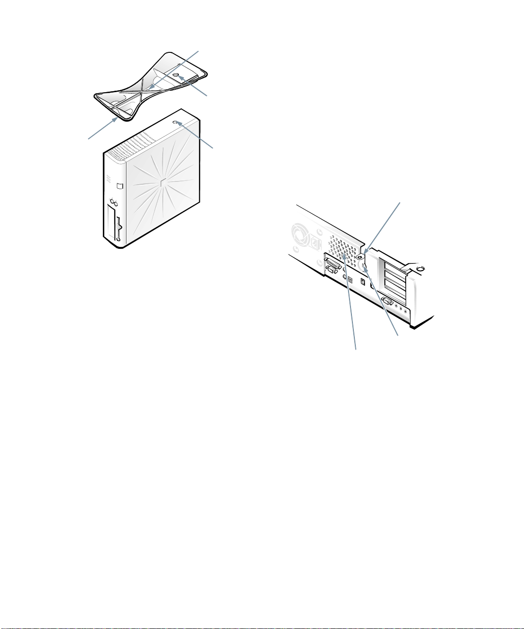
security cable slot
fan vent
Figure 1-2. Security Cable Slot and Padlock
Ring
nergy Star Compliance
E
ecurity Cable Slot and Padlock
S
Ring
To the right of the fan vent on the back of the computer
are a security cable slot and padlock ring ( see Figure 1-2)
for attaching a commercially available antitheft device.
Antitheft cable devices for personal computers usually
include a segment of galvanized cable with an attached
locking device and key. To prevent unauthorized removal
of your computer, loop the cable around an immovable
object, insert the locking device into the security cable
1-4 Dell OptiPlex GXi Low-Profile Systems Reference and Installation Guide
Certain configuration s of Dell com puter systems comply
with the requirements set forth by the Environmental
Protection Agency (EPA) for energy-efficient computers.
If the front panel of your computer bears the Energy Star
Emblem (see Figure 1-3), your original configuration
complied with these requirements and all Energy Star
power management features of the computer are enabled.
To disable or change the operation of these features, you
must change the setting for the
category in the System Setup program. For instructions,
see Chapter 2, “Using the System Setup Program.”
POWER MANAGEMENT
Page 29

NOTES: As an Energy Star Partner, Dell Computer Corporation has determined that this product meets the
Energy Star guidelines for energy efficiency.
Any Dell computer bearing the Energy Star Emblem is
certified to comply with EPA Energy Star requirements
configured when shipped by Dell
make to this configuration (such as installing additional
expansion cards or drives) may increase the system’s
power consumption beyond the limits set by the EPA’s
Energy Star Computers program.
Figure 1-3. Energy Star Emblem
The EPA's Energy Star Computers program is a joint
effort between the EPA and computer manufacturers to
reduce air pollution by promoting energy-efficient computer products. The EPA estimates that use of Energy
Star computer products can save computer users up to
two billion dollars annually in electricity costs. In turn,
this reduction in electricity usage can reduce emissions of
carbon dioxide, the gas primarily responsible for the
greenhouse effect, and sulfur dioxide and nitrogen
oxides, which are the two primary causes of acid rain.
Computer users can also help to reduce electricity usage
and its side effects by turning off their computer systems
when they are not in use for extended periods of time—
particularly at night and on weekends.
mportant Note to Windows 95
I
. Any changes you
TM
as
Users
For the Microsoft Windows 95 operat ing system to work
correctly on your computer system, you
sion of Windows 95 t h at Dell i n st all ed o n your computer.
use the ver-
must
Should you need to reinstall Wind ows 95 on an OptiPlex
GXi system
install the correct version. Dell recommends performing
a periodic tape backup of the system’s entire hard-disk
drive so that, if necessary, the operating system, drivers,
and other software can be reinstalled as originally configured with a minimum of downtime.
If you are unable to reinstall your software from a tape
backup of the hard-disk drive, you can reinstall Windows 95 from the system’s Windows 95 backup media
(CD or diskettes) that you received from Dell or created
from the Dell-installed software on your system.
ever, if you reinstall Windows 95 in this manner, the busmastering functionality of the Windows 95 EIDE driver,
which was operative in your or iginal configuration, will
be disabled
mastering functionality with only a small degradation in
performance. For information o n the ad vantag es of using
bus-mastering drivers, see “Bus-Mastering IDE Drivers”
in the online
reinstall your system’s video, audio, and NIC drivers
from the diskettes created from the Dell-installed so ftware on your system.
NOTE to system administrators of corporate networ ks:
If you must download W indows 95 f rom a se rver to cli ent
systems, make sure that you have the Windows 95 backup
media for the OptiPlex GXi system on your server before
downloading.
A
for any reason, you must be sure to re-
. (Your system will operate without the bus-
System User’s Guide.) You may also need to
ccessing Online
How-
Documentation
The online
disk drive contains information on the following topics:
•
•
•
•
•
•
•
•
System User’s
How to use the online
System features
Video drivers and utilities
Using the integrated audio controller
System Setup program
Configuring expansion cards
Securing your computer
Connecting external devices
Guide installed on your hard-
System User’s Guide
Introduction 1-5
Page 30

•
Maintaining the system
•
Contacting Dell
The guide also contains a glossary of commonly used
terms and abbreviations.
The
System User’s Guide
ries program group or folder.
To print any of the topics from this guide, display the
topic you want on your screen, and select PRINT TOPIC
from the File menu.
NOTE: Text in pop-up windows cannot be printed.
is located in the Dell Accesso-
etting Help
G
Dell provides a number of tools to help you if you don’t
understand a procedure described in this guide or if your
system does not perform as expected. For in formatio n on
these help tools, see the chapter titled “Getting Help” in
Diagnostics and Troubleshooting Guide
your
“Contacting Dell” section in the online
Guide
.
or the
System User’s
1-6 Dell OptiPlex GXi Low-Profile Systems Reference and Installation Guide
Page 31

Chapter 2
Using the System Setup Program
E
ach time you turn on your computer system or press
the reset button, the system compares the hardware
installed in the system to the hardware listed in the system configuration information stored in nonvolatile
random-access memory (NVRAM) on the system board.
If the system detects a discrepancy, it generates error
messages that identify the incorrect configuration settings. The system then prompts you to enter the System
Setup program to correct the setting.
You can use the System Setup program as follows:
•
To change the system configuration information
after you add, change, or remove any hardware in
your system
•
To set or change user-selectable options—for
example, the time or date on your system
You can view the current settings at any time. When you
change a setting, in many cases you must reboot the system before the change takes effect.
After you set up your system, run the System Setup
program to familiarize yourself with your system
configuration information and optional settings. Dell recommends that you print out the System Setup screens (by
pressing the <
mation for future reference.
Before you use the System Setup program, you need to
know the kind of diskette drive(s) and hard-disk drive(s)
installed in your computer. If you are unsure of any of
this information, see the Manufacturing Test Report that
was shipped with your system. You can acc ess the Man ufacturing Test Report from the Dell Accessories folder or
program group.
PRINT SCRN
> key) or write down the infor-
ntering the System Setup
E
Program
Enter the System Setup program as follows:
1. Turn on (or reboot) your system.
2. Press <
your computer's speaker emits a beep.
If you wait too long and your operating system begins to
load into memory, let the system complete the load oper-
ation; then shut down the system and try again.
NOTES: To ensure an orderly system shutdown, co nsult
the documentation that accompanied your operating
system.
If your system is running Microsoft Windows 3.1x or
later, Microsoft Windows 95, or any other protectedmode operating system, you are advised not to enter the
System Setup program from an MS-DOS window.
Instead, enter the System Setup program as described in
the previous procedure. Al t er nat ivel y, to get an MS-DOS
prompt in Windows 95, you can press <F8> when the
Starting Windows 95 message appe ars; then press
<CTRL><ALT><ENTER>
Another way of entering the System Setup program is to
shut down the system, boot from an MS-DOS diskette,
and then press <
If your system is running MS-DOS, you can enter the
System Setup program fr om the oper ating sys tem prompt
by holding down the <
ing the <
You can also enter the System Setup program by
responding to certain error messages. See “Responding to
Error Messages” at the end of this chapter.
CTRL><ALT><ENTER
.
CTRL><ALT><ENTER
CTRL
ENTER
> key.
> and <
> immediately after
>.
ALT
> keys and press-
Using the System Setup Program 2-1
Page 32

ystem Setup Screens
S
Table 2-1. System-Setup Navigation Keys
The two System Setup screens, Page 1 and Page 2, display the current setup and configuration information and
optional settings for your system. (Typical examples are
illustrated in Figure 2-1.) Information on the two System
Setup screens is organized in five boxed areas:
•
Title box
The box at the top of both screens lists the system
name, page number (Pag e 1 or Page 2), and the revision number of the basic input/output system
(BIOS).
•
Configuration options
The box on the left half of both screens lists t he cat egories that define the installed hardware in your
computer.
Fields beside the categories contain options or values. You can change those that appear bright on the
screen. Options or values that you cannot change
because they are determined by the system appear
less bright.
Some categories have multiple fields, which may
show options or values as bright or less bright,
depending upon what options or values you entered
in other fields.
•
Help
The box on the upper-right half of both screens displays help information for the category with a
currently highlighted field.
•
System data
The box in the lower-right corner of both screens
displays inform ation about your system.
•
Key functions
The line of boxes across the bottom of both screens
lists keys and their functions within the Sy stem
Setup program.
Keys Action
or
or
or
or
Moves to the next field.
Moves to the previous field.
Cycles through the options in a
field. In many fields, you can
also type in the appropriate
value.
Scrolls through help information.
Switches between Pages 1
and 2.
Exits the System Setup program without rebooting the
system and returns the system
to its previous state—the boot
routine or operating system
prompt.
For most of the categories, any
changes you made are recorded
but do not take effect until the
next time you boot the system.
For a few categories (as noted
in the help area) the changes
take effect immediately.
Exits the System Setup program and reboots the system,
implementing any changes you
made.
sing the System Setup Program
U
Table 2-1 lists the keys you use to view or change information on the System Setup screens and to exit the
program.
2-2 Dell OptiPlex GXi Low-Profile Systems Reference and Installation Guide
CAUTION: Any unsaved
data in open application programs will be lost when you
use this key combination.
Page 33

configuration options
Page 1 of 2
Dell Computer Corporation
System OptiPlex GXi 5200L Setup
title box
BIOS Version:
help
XXX
Time: 13:17:02
Diskette Drive A:
Diskette Drive B:
Drive A Location:
Drives:
Primary Type Cyls Hds Pre LZ Sec Size
Drive 0: Auto 524 32 -1 524 63 540
Drive 1: None
Date: Mon Jan 6, 1997
3.5 inch, 1.44 MB
Not Installed
Top
This category sets the time in
24-hour format (hours:minutes:
seconds) for the internal clock/
calendar.
To change the value in a field,
enter a number or use the leftor right-arrow key.
Secondary
Drive 0: Auto Packet Interface Device
Drive 1: None
Microprocessor: Pentium-200
Base Memory: 640 KB
Extended Memory: 15 MB
Reserved Memory: None
CPU Speed: 200 MHz
Num Lock: On
Tab,Shift-Tab change fields
change values
key functions
Alt-P next
Dell Computer Corporation
Page 2 of 2 System OptiPlex GXi 5200L Setup
Keyboard Errors: Report
System Password: Not Enabled
Password Status: Unlocked
Boot Sequence: Diskette First
This category determines whether
keyboard-related error messages are
reported at system startup.
Setup Password: Not Enabled
Auto Power On: Disabled 00:00
Power Management: Disabled
Integrated Devices
Sound: On
NIC (TX): On
Mouse: On
Serial Port: Auto
Parallel Port: 378h
Parallel Mode: AT
Hard Disk: Auto
Microprocessor: Pentium-200
External Cache: 256 KB
Diskette: Auto
USB: Off
Speaker: On
ECC: On
Tab,Shift-Tab change fields
change values
Alt-P next
External Cache: 256 KB
Video Memory: 2 MB
System Memory: 16 MB (EDO)
Service Tag:
Asset Tag:
Esc exit
system data
XXXXX
XXXXX
Alt-B reboot
BIOS Version:
Video Memory: 2 MB
System Memory: 16 MB (EDO)
Service Tag:
Asset Tag:
Esc exit
XXXXX
XXXXX
Alt-B reboot
XXX
Figure 2-1. System Setup Screens
Using the System Setup Program 2-3
Page 34

ystem Setup Categories
S
The following subsections explain in detail each of the
categories on the System Setup screens.
Time
TIME resets the time on the computer’s internal clock.
Time is kept in a 24-hour format (
). To change the time, press the right-arrow key to
onds
hours:minutes:sec-
increase the number in the highlighted field or press the
left-arrow key to decrease the number. If you pref er, you
can type numbers in each of the appropriate fields.
Date
DATE resets the date on the computer’s internal calendar.
Your system automatically displays the day of the week
corresponding to the settings in the three fields that follow (
month, day-of-month
, and
year
).
To change the date, press the right-arrow key to increase
the number in the highlighted field or press the left-arrow
key to decrease the number. If you prefer, you can type
numbers in the
month
and
day-of-month
fields.
Diskette Drive A and Diskette Drive B
DISKETTE DRIVE A and DISKETTE DRIVE B identify the
type of diskette drives installed in your computer. With
the standard cabling configuration, DISKETTE DRIVE A
(the boot diskette drive) is the 3.5-inch diskette drive
installed in the top externally accessible drive bay; DIS-
KETTE DRIVE B is any drive installed in the bottom
externally accessible drive bay that is connected to the
system’s diskette/tape drive interface.
The category options always match the physical locations
of the drives in your computer—the first drive lis t ed on
Page 1 of the System Setup screens is the top drive in
your computer.
The options are:
•
5.25 INCH, 360 KB
•
5.25 INCH, 1.2 MB
•
3.5 INCH, 720 KB
•
3.5 INCH, 1.44 MB
•
NOT INSTALLED
NOTE: Tape drives are not reflected in the
DRIVE A
DISKETTE DRIVE B
and
categories. For example,
DISKETTE
if you have a single diskette drive and a tape drive
attached to the diskette/tape drive interface cable, set the
DISKETTE DRIVE A
of the diskette drive and set the
gory to
NOT INSTALLED
category to match the characteristics
DISKETTE DRIVE B
cate-
.
Drive A Location
DRIVE A LOCATION identifies which diskette drive—TOP
(the default option) or BOTTOM (if existing)—is used as
drive A, the boot drive.
The letters A and B in the categories DISKETTE DRIVE A
and DISKETTE DRIVE B are switched automatically when
DRIVE A LOCATION is changed to reflect the new
configuration.
If an external diskette drive controller is being used,
DRIVE A LOCATION becomes a nonselectable category.
Drives: Primary and Secondary
PRIMARY identifies drives attached to the primary
enhanced integrated drive electronics (EIDE) interface
connector (labeled “IDE1”) on the system board; SEC-
ONDARY identifies drives connected to the secondary
EIDE interface connector (labeled “IDE2”). It is recommended that you use the secondary EIDE interface
connector for EIDE CD-ROM and EIDE tape drives.
NOTES: For all devices from Dell that u se the built-in
EIDE controller, set the appropriate
AUTO
.
You must have an EIDE device connected to the primary
EIDE interface if you have an EIDE device connected to
the secondary EIDE interface.
For both the PRIMARY and SECONDARY drive sections, the
DRIVE 0 and DRIVE 1 categories identify the type of EIDE
devices installed in the computer. For each drive, seven
parameters can be chosen as a group by drive-type
number, entered individually from the keyboard or set
automatically. A
drive-type number
ters of a hard-disk drive based on a table recorded in the
system’s BIOS.
DRIVE
category to
specifies the parame-
2-4 Dell OptiPlex GXi Low-Profile Systems Reference and Installation Guide
Page 35

To choose a setting for these categories, type characters
from the keyboard or use the left- or right-arrow key to
cycle through the choices. The options are:
•
AUTO (use this setting for all EIDE devices from
Dell)
•
NONE
•
USER1 or USER2
•
A specific drive-type number
NOTE: Operating systems that bypass the system BIOS
may not obtain optimum hard-disk drive performanc e.
EIDE Devices
For EIDE hard-disk drives, the system provides an automatic drive-type detect feature. To use this feature for
DRIVE 0, highlight the DRIVE 0 category in the PRIMARY
drive section and type a (for
DRIVE 1, highlight the DRIVE 1 category and type
automatic
each case, the category setting changes to AUTO. After
you reboot the system, the System Setup program automatically sets the correct drive-type number and
parameters for each drive.
Before installing a new EIDE hard-disk drive, also check
the documentation that came with the drive to verify that
all jumper settings on the drive are appropriate for your
configuration.
If You Have a Problem
If the system generates a drive error message the first
time you boot your system after installing an EIDE drive,
it may mean that your particular drive does not work with
the automatic drive-type detect feature. If you suspect
that your problem is related to drive type, try entering
your drive-type infor mation in on e of the fo llo wing ways .
If You Know the Drive-Type Number
Use the drive-type number you found in the documentation that came with the drive or, if the drive was installed
by Dell when you purchased your system, access the
Manufacturing Test Report from the Dell Accessories
folder or program group.
To set the drive-type number in the System Setup program, highlight the appropriate drive category (DRIVE 0 or
DRIVE 1 in the PRIMARY drive section) and type the cor-
rect drive-type number. If you prefer, you can press the
). To use it for
a
. In
right- or left-arrow key to increase or decrease, respectively, the drive-type number until the correct one is
displayed.
If You Do Not Know the Drive-Type Number
The DRIVE 0 and DRIVE 1 categories display the following
seven parameters for each drive:
•
TYPE is the drive-type number for the selected hard-
disk drive.
•
CYLS is the number of logical cylinders.
•
HDS indicates the number of logical heads in the
drive.
•
PRE (
precompensation cylinder
) is the cylinder number at which the electrical current for the drive head
changes to compensate for differences in data density across the disk surface (this parameter has no
effect for EIDE drives).
•
LZ is the cylinder number that is used as the
drive’s landing zone for the heads when the drive
is not in use.
•
SEC is the number of logical sectors per track.
•
SIZE (automatically calculated by the system) indi-
cates the number of millions of bytes of storage
provided by the drive.
If none of the supported drive types mat ch the parameters
of your new drive, you can enter your own parameters.
To do so, highlight the DRIVE 0 category and type u to
display USER1. You can then use the right- or left-arrow
key to switch between the USER1 and USER2 settings
(only two user-defined drive types are allowed). Then
press the <
TAB
> key to highlight each of the parameter
fields in succession, and enter the appropriate number for
each field.
NOTE: The
both the
SECONDARY
and
USER1
the
mum hard-dis k drive performance. Also, the
USER2
USER1 and USER2
DRIVE 0
and
DRIVE 1
drive types can be used for
categories in the
PRIMARY
drive sections. However, if you select
USER2
or
drive type, you may not obtain opti-
USER1
and
drive types cannot be used for hard-disk drives
greater than 52 8 megabytes (MB) i n c apacity.
Using the System Setup Program 2-5
Page 36

Base Memory
BASE MEMORY disp l ays t he amou nt o f memory available
to MS-DOS programs that do not use extended or
expanded memory. This category has no user-selectable
options.
The default value for the BASE MEMORY category is
640 KB, which includes 1 kilobyte (KB) reserved for sys-
tem use.
Extended Memory
EXTENDED MEMORY, which has no user-selectable
options, indicates the amount of memory available as
extended memory. The value given is in meg abytes rather
than kilobytes. To convert megabytes to kilobytes, m ultiply the megabyte total by 1024.
You can also toggle between the rated processor speed
and the compatibility speed while the system is run ning
in real mode by pressing <
CTRL><ALT><\
>. (For key-
boards that do not use American English, press
CTRL><ALT><#
<
>.)
Num Lock
NUM LOCK determines whether your system boots with
the Num Lock mode activated on 101- or 102-key keyboards (it does not apply to 84-key keyboards).
When Num Lock mode is activated, the rightmost bank
of keys on your keyboard provides the mathematical and
numeric functions shown at the tops of the keys. When
Num Lock mode is turned off, these keys provide cursorcontrol functions according to the labels on the bottom of
each key.
Reserved Memory
RESERVED MEMORY allows you to designate a region of
system board memory that can be supplied by an expansion card. You should not enable the reserved memory
feature unless you are using an expansion card that
requires special addressing.
For example, you may have a memory expansion card
that needs to be addressed starting at 15 MB. Selecting
the 15M - 16M option in the RESERVED MEMORY category
specifies that only part of the base memory comes from
the dual in-line memory modules (DIMMs) on the system board, whereas the base memory from 15 to 16 MB
comes from the memory expansion card.
The RESERVED MEMORY category has the following
options:
•
NONE (the default option)
•
15M - 16M
CPU Speed
CPU SPEED indicates the processor speed at which your
system boots.
Press the left- or right-arrow key to toggle the CPU
SPEED category between the resident microprocessor’s
rated speed (the default) and a lower compatibility speed,
which lets you accommodate speed-sensitive application
programs. A change to this category takes effect immediately (rebooting the system is not required).
Keyboard Errors
KEYBOARD ERRORS enables or disables repo rti ng o f key-
board errors during the p ower-on self-test (POST), which
is a series of tests that the system performs on the hardware each time you turn on the system or press the reset
button.
This category is useful when applied to self-starting servers or host systems that have no permanently attached
keyboard. In these situations, selecting DO NOT REPORT
suppresses all error messages relating to the keyboard
or to the keyboard controller during POST. This
option does not affect the operation of the keyboard
itself, if one is attached to the computer.
System Password
SYSTEM PASSWORD displays the current status of your
system’s password security feature and allows you to
assign and verify a new password. No one can assign a
new password unless the current status is NOT ENABLED,
which is displayed in bright characters.
The options for the SYSTEM PASSWORD category are:
•
NOT ENABLED (the d e fault option)
•
ENABLED
•
DISABLED BY JUMPER
NOTE: Read “Using the System Password Feature”
found later in this chapter for instructions on assigning a
2-6 Dell OptiPlex GXi Low-Profile Systems Reference and Installation Guide
Page 37

system password and using or changing an existing system password. See “Disabling a Forgotten Password ”
found later in this chapter for instructions on disabling a
forgotten system password.
Password Status
When SETUP PASSWORD is set to ENABLED, PASSWORD
STATUS allows you to prevent the system password from
being changed or disabled at system start-up.
To lock the system password, you must first assign a
setup password and then change the PASSWORD STATUS
category to LOCKED. In this state, the system password
cannot be changed through the SYSTEM PASSWORD category and cannot be disabled at system start-up by
pressing <
CTRL><ENTER
>.
To unlock the system pas swo rd, you mu st ent er th e setup
password and then change the PASSWORD STATUS category to UNLOCKED. In this state, the system password
can be disabled at system start-up by pressing
CTRL><ENTER
<
PASSWORD category.
> and then changed through the SYSTEM
Boot Sequence
BOOT SEQUENCE can be set to DISKETTE FIRST (the
default option) or HARD DISK ONLY.
The term
cedure. When turned on, the system “bootstraps”
itself into an operational state by loading into memory
a small program, which in turn loads the necessary
operating system. BOOT SEQUENC E t ells th e system
where to look for the files that it needs to load.
Selecting DISKETTE FIRST causes the system to try
booting from drive A first. If it finds a di skette tha t is
not bootable in the drive or finds a problem with the
drive itself, the system displays an error message. If it
does not find a diskette in the drive, the system then
tries to boot from the hard-disk drive (drive 0).
Selecting HARD DISK ONLY causes the system to boot
from the hard-disk drive, even if there is a boot-
only
able diskette in drive A.
refers to the system’s start-up pro-
boot
Setup Password
SETUP PASSWORD lets you restrict access to your com-
puter’s System Setup program in the same way that you
restrict access to your system with the system password
feature. The options are:
•
NOT ENABLED (the de fault o ption)
•
ENABLED
•
DISABLED BY JUMPER
NOTE: Read “Using the Setup Password Feature” found
later in this chapter for instructions on assigning a setup
password and using or changing an existing setup password. See “Disabling a Forgotten Password” found later
in this chapter for instructions o n disabling a forgotten
setup password.
Auto Power On
AUTO POWER ON allows you to set the time and days of
the week to turn on the computer system automatically.
You can set AUTO POWER ON to turn on the system either
every day or every Monday through Friday.
NOTE: This feature will not work if you shut off your system using a power strip or surge protector.
Time is kept in a 24-hour format (hours:minutes). To
change the start-up time, press the right-arrow key to
increase the number in the highlighted field or press the
left-arrow key to decrease the number. If you prefer, you
can type numbers in both of the appropriate fields.
The default for AUTO POWER ON is DISABLED.
Power Management
For certain types of monitors and most EIDE hard-disk
drives, you can reduce system power consumption by
enabling the power management feature. With POWER
MANAGEMENT enabled, these monitors and drives auto-
matically switch into low-power mode during periods o f
system inactivity.
POWER MANAGEMENT can be implemented at three
levels—MAXIMUM, REGULAR, and MINIMUM. (The different levels apply to the monitor only; hard-disk drive
operation is the same for all three.) The default setting for
this category is DISABLED.
Using the System Setup Program 2-7
Page 38

Saving Monitor Power
If you have a Video Electronics Standards Association
(VESA®) Display Power Management Signaling
(DPMS)-compliant monitor, enabling the POWER MAN-
AGEMENT category reduces monitor power consumption
during periods of keyboard and mouse inactivity
.
CAUTION: Check your monitor documentation to
make sure you have a DPMS-compliant monitor
before you enable this feature. Otherwise, you risk
damaging the monitor.
NOTE: The power management feature monitors activity of
a mouse connected to the Personal System/2 (PS/2)compatible mouse port.
By setting POWER MANAGEM ENT to MAXIMUM, REGU-
LAR, or MINIMUM, you can set predefined time-out periods
(see Table 2-2) for the two successive monitor shutdown
stages,
standby
and
off
.
NOTE: Each monitor manufacturer defines the details of
the shutdown stages for its own monitors. But in all
cases, power consumption decreases with each stage
from “on” (full powe r) to “stand by” (reduced power ; the
display image usually disap pears) to “off ” (where power
consumption is minimal). To define these stages for your
monitor, see the documentation that came wit h the
monitor.
From either shutdown stage, you can return full power to
the monitor in one of the following ways:
•
For most DPMS-compliant monitors, any subsequent activity—including moving the mouse—
should return full power to the monitor.
•
A few DPMS-compliant monitors require that you
turn monitor power off and then on again to return to
full power.
Check your monitor documentation for information on
how your monitor is designed to operate.
Saving EIDE Hard-Disk Drive Power
For most systems, enabling POWER MANAGEMENT at any
level causes EIDE hard-disk drives to switch to lowpower mode after about 20 minutes of system inactivity
(see Table 2-2).
NOTES: All EIDE drives shipped with your system
support this feature. (For more information on Energy
Star systems, see “Energy Star Compliance” in
Chapter 1.)
However, not all EIDE hard-disk drives support this feature. Enabling this feature for drives that do not support
it may cause the EIDE drive to become inoperable until
the computer is restarted and the
POWER MANAGEMENT
category is disabled.
In low-power mode, the disks inside the drive stop spinning. They remain idle until the next drive access, which
causes them to start spinning again. (Because the disks
take a few seconds to regain ful l speed, you may notice a
slight delay when you next access the hard-disk drive.)
When POWER MANAGEMENT is set to
DISABLED (the
default), the disks spin constantly as long as the system is turned on.
Table 2-2. Power Time-Out Periods
Power
Management
Setting
Disabled
Maximum
Regular
Minimum
EIDE Drive
Spindown
Time-Outs
Monitor
Standby
Time-Outs
Never Never Never
20 minutes 10 minutes 1 hour
20 minutes 20 minutes 1 hour
20 minutes 1 hour Never
Monitor
Off
TimeOuts
Sound
SOUND determines whether the integrated audio control-
ler is ON or OFF. You must reboot your system before a
change takes effect.
NIC
NIC determines whether the network interface controller
(NIC) is ON or OFF. You must reboot your system before
a change takes effect.
2-8 Dell OptiPlex GXi Low-Profile Systems Reference and Installation Guide
Page 39

Mouse
MOUSE enables or disables the system ’s built-in PS/2-
compatible mouse port. Disabling the mouse allows an
expansion card to use interrupt request (IRQ) 12.
Serial Port
SERIAL PORT configures the system’s built-in serial port.
This category can be set to
AUTO (the default option) to
automatically configure the port to a particular designation (
COM1 through COM4) or to OFF to disable the port.
If you set the serial port to
AUTO and add an expansion
card containing a port configured to the same designation, the system automatically remaps the built-in port to
the next available port designation that shares the same
IRQ setting:
•
COM1 (input/output [I/O] address 3F8h), which
shares IRQ4 with COM3, is remapped to COM3
(I/O address 3E8h).
•
Likewise, COM2 (I/O address 2F8h), which shares
IRQ3 with COM4, is remapped to COM4 (I/O
address 2E8h).
NOTE: When two COM port s share an IRQ setting, you
can use either port as nece ssary, bu t
to use them both at the same time
you may not be able
.
For more information about built-in ports , port designations, IRQs, and the remapp ing of p orts, s ee “Conn ecting
External Devices” in your online System User’s Guide.
Parallel Port
PARALLEL PORT configures the system’s built-in parallel
port. This category can be set to
alternate addresses
278H or 3BCH, or to OFF to disable the
378H (the default), to
port.
NOTE: Do not set
PARALLEL PORT
to
278H
if you have
an Enhanced Capabilities Port (ECP) device connected
to the port.
Parallel Mode
PARALLEL MODE controls whether the system’s built-in
parallel port acts as an AT-compatible (unidirectional) or
PS/2-compatible (bidirectional) port.
Your system also support s ECP mode, which can be us ed
by the Windows 95 operating system. Windows 95 uses
ECP protocol automatically if it detects an ECP-capable
device, removing the necessity for an ECP option in this
category.
Set this category according to the type of peripheral
device connected to the parallel port. To determine the
correct mode to use, see the documentation that came
with the device.
Hard Disk
HARD DISK enables or disables the system’s built-in EIDE
hard-disk drive interface.
With
AUTO (the default option) selected, the system turns
off the built-in EIDE interface when necessary to accommodate a controller card installed in an expansion slot.
As part of the boot routine, the system first checks for a
primary hard-disk drive controller card installed in an
expansion slot. If no card is found, the system enabl es the
built-in EIDE interface to use IRQ14 and IRQ15.
If a primary controller is detected on the expansion bus,
the built-in EIDE interface is disabled.
Selecting
OFF disables the built-in EIDE interface.
Diskette
DISKETTE controls the operation of the system’s built-in
diskette drive controller.
With
AUTO (the default option) selected, the system turns
off the built-in diskette drive controller when necessary
to accommodate a controller card installed in an expansion slot.
With
WRITE-PROTECT selected, nothing can be written to
diskette drives and tape drives using the system’s built-in
diskette drive controller. (The system can still read from
the drives.) When this option is selected, the
(whereby the system turns off the built-in diskette drive
controller as necessary) is also in effect.
Selecting
OFF turns off the built-in diskette/tape drive
controller; this option is used primarily for troubleshooting purposes.
AUTO option
Using the System Setup Program 2-9
Page 40

USB
USB determines whether the Universal Serial Bus (USB)
connectors on the system board are turne d ON or OFF (the
default). You must reboot your system before a change
takes effect.
Speaker
SPEAKER determines whether the onboard speaker is ON
(the default) or OFF. A change to this category takes
effect immediately (rebooting the system is not required ).
ECC
ECC determines whether the system’s error correction
code (ECC) capability is turned ON (the default) or OFF.
Your system supports ECC only if all the installed
DIMMs are ECC DIMMs. If any of the installed DIMMs
are not ECC DIMMs, this category does not appear.
System Data Categories
The following categories, which are not selectable, display information about the system:
•
MICROPROCESSOR displays the type of micro-
processor installed in the computer.
•
EXTERNAL CACHE displays the size of the onboard
cache (256 KB or 512 KB).
•
VIDEO MEMORY displays the amount of video mem-
ory detected in your system.
•
SYSTEM MEMORY indicates the entire amount of
installed memory detected in your system, except for
memory on Expanded Memory Specification (EMS)
expansion cards. After adding memory, check this
category to confirm that the new memory is installed
correctly and is recognized by the system.
•
SERVICE TAG displays the system’s five-character
service tag number, which was programmed into
NVRAM by Dell during the manufacturing process.
Refer to this number during technical assistance or
service calls. The service tag number is also
accessed by certain Dell support software, including
the diagnostics software.
•
ASSET TAG displays the customer-programmable
asset tag number for the system if an asset tag number has been assigned. You can use the Asset Tag
utility, which is included with your software support
utilities, to enter an asset tag number up to ten characters long into NVRAM. For information on using
the utility, see “Using Drivers and Utilities” in your
online
System User’s Guide
sing the System Password
U
.
Feature
CAUTION: The password features provide a basic
level of security for the data on your system. However, they are not foolproof. If your data requires
more security, it is your responsibility to obtain and
use additional forms of protection, such as data
encryption programs.
Your Dell system is shipped to you without the system
password feature enabled. If system security is a concern,
you should operate your system only with system password protection.
You can assign a system password, as described in the
next subsection, “Assigning a System Password,” whenever you use the System Setup program. After a system
password is assigned, only those who know the password
have full use of the system.
When the SY ST EM PASSWORD category is set to
ENABLED, the computer system prompts you for the sys-
tem password just after the system boots.
To change an existing system password, you must know
the password (see “Deleting or Changing an Existing
System Password” found later in this section). If you
assign and later
be able to remove the computer cover to change a
jumper setting that disables the system password feature (see “Disabling a Forgotten Password” found
later in this chapter). Note that you erase the
password
at the same time.
a system password, you need to
forget
setup
2-10 De ll Op tiPlex GXi Low-Profile Systems Reference and Installation Guide
Page 41

CAUTION: If you leave your system running and
unattended without having a system password
assigned or leave your computer unlocked so that
someone can disable the password by changing a
jumper setting, anyone can access the data stored
on your hard-disk drive.
Assigning a System Password
Before you can assign a system passwor d, you must enter
the System Setup program and check the SYSTEM PASS-
WORD category.
When a system password is assigned, the option shown i n
the SYSTEM P ASSWO RD categ ory is ENABLED. When
the system password feature is disabled by a jumper setting on the system board, the option shown is DISABLED
BY JUMPER.
password if either of th ese options is displa yed.
When no system password is assigned and the password
jumper on the system board is in the enabled position (its
default setting), the option shown for the SYSTEM PASS-
WORD category is NOT ENABLED.
category is set to
password
1. Verify that the
to
For instructions on changing the setting for PASS-
WORD STATUS, see “Password Status” found earlier
in this chapter.
2. Highlight the
then press the left- or right-arrow key.
The category heading changes to ENTER PASSWORD,
followed by an empty seven-character field in square
brackets.
3. Type in your new system password.
You can use up to seven characters in your password.
As you press each character key (or the <
for a blank space), a placeholder appears in the field.
The password assignment op erat i on recog nizes keys
by their location on the keyboard, without distinguishing between lowercase and uppercase
characters. For example, if you have an
password, the system recognizes either
correct.
You cannot change or enter a new sys t em
Only when this
NOT ENABLED
can you assign a system
, using the following procedure:
category is set
category, and
UNLOCKED
PASSWORD STATUS
.
SYSTEM PASSWORD
SPACEBAR
in your
M
m
or
M
as
Certain key combinations are not valid. If you enter
one of these combinations, the speaker emits a beep.
To erase a character when entering your password,
press the <
BACKSPACE
> key or the left-arrow key.
NOTE: To escape from the field without assigning a
system password, press the <
<
SHIFT><TAB
> key combination to move to another
> key or the
TAB
field, or press the <ESC> key at any time prior to
completing step 5.
4. Press <
ENTER
>.
If the new system password is less than seven characters, the whole field fills with placeholders. Then
the category heading changes to VERIFY PASSWORD,
followed by another empty seven-character field in
square brackets.
5. To confirm your password, type it in a second
time and press <
ENTER
>.
The password setting changes to ENABLED. Your
system password is now set; you can exit the System
Setup program and begin using your system. Note,
however, that password protection does not take
effect until you reboot the system by pressing the
reset button or by turning the system off and then on
again.
Using Your System Password to Sec ure Your System
Whenever you turn your system on, press the reset
button, or reboot the system by pressing the
CTRL><ALT><DEL
<
prompt appears on the screen:
Type in the password and ...
— press <ENTER> to leave password
security enabled.
— press <CTRL><ENTER> to disable password
security.
>
Enter password:
After you type the correct system password and press
ENTER
<
>, your system boots and you can use the key-
board to operate your system as usual.
NOTE: If you have assigned a setup password (see
“Using the Setup Password Feature” found later in this
chapter), the system accepts your setup password as an
alternate system password.
> key combination, the following
Using the System Setup Program 2-11
Page 42

If a wrong or incomplet e s ystem pas swo rd is en te red, the
following message appears on the screen:
** Incorrect password. **
Enter password:
If an incorrect or incomplete system password is entered
again, the same message appears on the screen.
The third and subsequent times an incorrect or incomplete system password is entered, the system displays
the following message:
** Incorrect password. **
Number of unsuccessful password
attempts: 3
System halted! Must power down.
The number of unsuccessful attempts made to enter the
correct system password can alert you to an unauthorized
person attempting to use your system.
Even after your system is turned off and on, the previous
message is displayed each time an incorrect or incomplete
system password is entered.
NOTE: You can use the
conjunction with
WORD
to further protect your system from unauthorized
PASSWORD STATUS
SYSTEM PASSWORD
SETUP PASS-
and
category in
changes. For more information, see “Password Status”
found earlier in this chapter.
Deleting or Changing an Existing
System Password
To delete or change an existing system password, perform the fo ll owing steps :
1. Enter the System Setup program and v erify that
the
PASSWORD STATUS
UNLOCKED
.
Enter the System Setup program by pressi ng the
CTRL><ALT><ENTER
<
ALT><P
<
> key combination to move to Page 2 of the
System Setup screens. For instructions on changing
the setting for
PASSWORD STATUS, see “Password
Status” found earlier in this chapter.
2. Reboot your system to force it to prompt you for
a system password.
3. When prompted, type in the system password.
category is set to
> key combination. Press the
4. Press the <
CTRL><ENTER
> key combination to
disable the existing system password, instead
of pressing <
> to continue with the
ENTER
normal operation of your system.
5. Confirm that
SYSTEM PASSWORD
NOT ENABLED
category of the System
is displayed for the
Setup program.
If
NOT ENABLED appears in the SYSTEM PASSWORD
category, the system password has been deleted. If
you want to assign a new password, continue to
step 6. If
SYSTEM PASSWORD category, press the <
NOT ENABLED
is not displayed for the
ALT><B
>
key combination to reboot the system, and then
repeat steps 3 through 5.
6. To assign a new password, follow the procedure in
“Assigning a System Password” found earlier in
this section.
sing the Setup Password
U
Feature
Your Dell system is shipped to you without the setup
password feature enabled. If system security is a concern,
you should operate your system with setup password
protection.
You can assign a setup password, as described in the next
subsection, “Assigning a Setup Password,” whenever
you use the System Setup program. After a setup password is assigned, only those who know the password
have full use of the System Setup program.
To change an existing setup password, you must know
the setup password (see “Deleting or Changing an Existing Setup Password” found later in this section). If you
assign and later forget a setup password, you need to be
able to remove the computer cover to change a jumper
setting that disables the setup password feature (see “Disabling a Forgotten Password” found later in this chapter).
Note that you erase the system password at the same
time.
Assigning a Setup Password
A setup password can be assigned (or changed) only
when the
ENABLED
SETUP PASSWORD category is set to NOT
. To assign a setup password, highlight the
2-12 D e ll OptiPlex GXi Low-Profile Systems Reference and Installati on Guid e
Page 43

SETUP PASSWORD category and press the left- or right-
arrow key. The system prompts you to enter and verify
the password. If a character is illegal for password use,
the system emits a beep.
NOTES: The setup password can be the same as the system password.
If the two passwords are different, the setup password can
be used as an alternate system password. However, the
system password cannot be used in place of the setup
password.
After you verify th e password , the SETUP PASSWORD
setting changes to ENABLED. The next time you enter the
System Setup program, the system prompts you for the
setup password.
A change to the SETUP PASSWORD category becomes
effective immediately (rebooting the system is not
required).
Deleting or Changing an Existing Setup Password
To delete or change an existing setup password, perform
the following steps:
1. Enter the System Setup program.
2. Highlight the SETUP PASSWORD category, and
press the left- or right-arrow key to delete the
existing setup password.
The setting changes to NOT ENABLED.
3. If you want to assign a new setup password, follow the procedure in “Assigning a Setup
Password” found earlier in this section.
isabling a Forgotten Password
D
Operating With a Setup Password Enabled
If SETUP PASSWORD is set to ENABLED, you must enter
the correct setup password before you can modify the
majority of the System Setup categories.
When you start the System Setup program, Page 2 of the
System Setup screens appears with the SETUP PAS S-
WORD category highlighted, prompting you to type in the
password.
If you do not enter the correct password in three tries, the
system lets you view, but not modify, the System Setup
screens—with the following exceptions:
•
You can still modify the DATE, TIME, CPU SPEED,
NUM LOCK, and SPEAKER categ ories.
•
If SYSTEM PASSWORD is not enabled and is not
LOCKED via the PASSWORD STAT US category, you
can assign a system password (however, you cannot
disable or change an existing system password).
NOTE: You can use the
in conjunction with
SYSTEM PASSWORD
For more information, see “Password Status” found
earlier in this chapter.
PASSWORD STATUS
SETUP PASSWORD
from unauthorized changes.
category
to protect
If you forget your system or setup password, you cannot
operate your system or change settings in the System
Setup program until you remove the computer cover,
change the password jumper setting to disable the passwords, and erase the existing passwords.
To disable a forgotten password, perform the following
steps:
1. Remove the computer cover according to the
instructions in “Removing the Computer Cover”
in Chapter 5.
CAUTION: See “Protecting Against Electrostatic Discharge” in the safety instructions at
the front of this guide.
2. Remove the jumper plug from the PSWD jumper
to disable the password feature.
Refer to “Jumpers” in Chapter 5 for jumper information and to Figure 5-7 for the location of the
password jumper (labeled “PSWD”) on the system
board.
3. Replace the computer cover.
Using the System Setup Program 2-13
Page 44

4. Reconnect your computer and peripherals to
their power sources, and turn them on. Proceed to
step 5 if you want to assign a new password.
Booting your system with the PSWD jumper plug
removed erases the existing password(s).
NOTE: Before you as sig n a new system an d/or setu p
password, you must replace the PSWD jumper plug.
5. Repeat step 1.
6. Replace the PSWD jumper plug.
7. Replace the computer cover, reconnect the computer and peripherals to their power sources, and
turn them on.
Booting with the PSWD jumper installed reenables
the password feature. When you enter the System
Setup program, both password categories appear as
NOT ENABLED, meaning that the password feature is
enabled but that no password has been assigned.
8. Assign a new system and/or setup password.
To assign a new system password, see “Assigning a
System Password” found earlier in this chapter. To
assign a new setup password, see “Assigning a Setup
Password” found earlier in this chapter.
esponding to Error Messages
R
If an error message appears on your monitor screen while
the system is booting, make a note of the message. Then,
before entering the System Setup program, refer to your
Diagnostics and Troubleshooting Guide for an explanation of the message and suggestions for correcting any
errors. However, it is normal to receive an error message
the first time you boot the system after a memory
upgrade. In that case, you do not need to refer to the
Diagnostics and Trou blesh ootin g Guide
the
instructions in “Performing a Memory Upgrade” in
Chapter 6 of this guide.
If you are given an option of pressing either <
tinue or <
F2
<
F2
> key.
> to run the System Setup program, press the
; instead, refer to
F1
> to con-
2-14 D e ll OptiPlex GXi Low-Profile Systems Reference and Installati on Guid e
Page 45

Chapter 3
Using the ISA Configuration Utility
he ISA Configuration Utility (ICU) is used by the
T
system to track what expansion cards are installed and
what resources are used. With this information, the system automatically configures Plug and Play expansion
cards and Peripheral Component Interconnect (PCI)
expansion cards and can tell you how to configure nonPlug and Play Industry-Standard Architecture (ISA)
expansion cards manually by setting jumpers or switches.
Plug and Play and PCI expansion cards do not contain
jumpers and switches; they are configured only through
software.
CAUTION: The ICU is intended only for configuring non-Plug and Play ISA expansion cards. It
should not be used for assigning resources to Plug
and Play expansion cards and PCI expansion
cards. These cards should be configured automatically by the basic input/output sy stem (BIOS).
NOTES: The Windows NT operating system does not
provide full Plug and Play suppor t. Therefore, so me Plug
and Play cards (such as modem, sound, and network
cards) may not work with Windows NT. If your system is
running a Dell-installed Windows NT operating system
and you want to use Plug and Play cards, Dell recommends that you use the card manufacturer’s utility to set
the card to legacy mode, enter the card’s resources
through the manufacturer’s utility, and then use the ICU
to add the Plug and Play card to your system configur ation. On systems with a Dell-installed Windows NT
operating system, the ICU is installe d on the hard-disk
drive as a diskette image. Use the Dell DiskMaker
(located in the Dell Accessories program group or
folder) to make an ICU diskette from this diskette image.
If you are using the Windows 95 operating sys t em, the
functions provided by the ICU are handled by the Device
Manager, which can be accessed by double-clicking the
System icon in the Control Panel. See your Windows 95
documentation for instructions on using the Device Manager to manage resources and resolve conflicts.
The remainder of this chapter describes the various features of, and the various ways to use, the ICU.
Q
uick Start
To quickly get started using this utility, follow these
steps:
1. Determine whether you need to run the ICU.
See “When to Run the ICU” found later in this chapter for detailed instructions.
2. Perform any required preparatory steps before
starting the utility.
Preparatory steps include making a program diskette, copying your mou se driver to this dis kette, and
making a backup copy of this diskette. See “Preparing to Use the ICU” found later in this chapter for
detailed instructions.
3. Start the syst em using your ICU diskette.
Verify that the
System Setup program is set to
Then insert the backup copy of the ICU di skette into
drive A, and turn on your computer or press the reset
button.
NOTE: The ICU takes a few minutes to load. During
this time, the cursor may appear as a pointer rather
than as an hou r glass.
When the utility has finish ed loading, the ICU window (see Figure 3-1) is displayed.
BOOT SEQUENCE
category in the
DISKETTE FIRST
.
Using the ISA Configuration Utility 3-1
Page 46

4. Add, modify, or remove a card, or view resources
for a card or other device.
Depending on what you need to accomplish with the
ICU, you may need to perform one or more of these
tasks:
•
If you are adding a non-Plug and Play ISA
expansion card, see your online System User’s
Guide or “Adding a Listed Card” found later in
this chapter for detailed instructions. If the card
you are adding does not have a configuration
file, see your online System User’s Guide or
“Adding an Unlisted Card” found later in this
chapter for detailed instructions.
•
If you are modifying a card that is already
installed, see your online System User’s Guide
or “Modifying a Card” found later in this chapter for detailed instructions.
•
If you are removing a card, see your online
System User’s Guide or “Removing a Card”
found later in this chapter for detailed
instructions.
•
If you want to examine the resources already
assigned in the system, see your online System
User’s Guide or “Viewing Resources” found
later in this chapter for detailed instructions.
5. Save your configuration, and exit the utility.
See your online System User’s Guide or “Saving the
System Configuration” and “Exiting From the ICU,”
found later in this chapter for detailed instructions.
A
bout the ICU
Before your system was shipped from Dell, a technician
used the ICU to enter the correct information for the
expansion cards initially installed in your compu ter.
If your system was shipped with Dell-installed software,
the ICU diskette image (from which you can make an
ICU diskette) is installed on your hard-disk drive. (Your
system may also be accompanied by an ISA Configura-
tion Utility Diskette.)
The ICU is also available through online services such as
Dell’s TechConnect bulletin board service (BBS). See
your online System User’s Guide or the chapter titled
“Getting Help” in your Diagnostics and Troublesho oting
Guide for information on accessing the BBS.
Whenever you add or remove a non-Plug and Play ISA
expansion card, use the ICU to reconfigure your system.
The utility reads the card’s corresponding con figuration
file (.cfg file), which describes the card’s characteristics
and required system resources. After the resources
identified in these configuration files are assigned to all
non-Plug and Play ISA expansion cards, the system
assigns resources to all Plug and Play expansion cards, as
well as PCI expansion cards, thereby creating a conflictfree configuration.
ICU Database
The ICU provides a database of configuration files for a
large variety of non-Plug and Play ISA expansion cards.
The database is located in the \db subdirectory. Listed
cards are non-Plu g and Play ISA expansion cards that have
configuration files stored in this database.
Unlisted cards are non-Plug and Play ISA expansion
cards that do not have configuration files stored in the
ICU database . Unlisted cards are not displayed in the li st
of cards provided for the various card categories. The
unlisted cards may be cards for which no configuration
file exists or new cards that include a manufacturersupplied configuration file on diskette.
When you supply a configuration file and the ICU is running from the hard-disk drive, the configuration file is
copied to the directory that contains the rest of the ICU
database.
See your on line System User’s Guide or “Adding a Listed
Card” found later in this chapter for directions on how to
add a listed non-Plug and Play ISA expansion card. See
your online System User’s Guide or “Addi ng an Unl is ted
Card” found later in the chapter for instructions on how
to add an unlisted non -Plu g and Play IS A expansion card.
W
hen to Run the ICU
Whenever you add or remove non-Plug and Play ISA
expansion cards, you must run the ICU to ensure that no
two cards attempt to use the same resources (such as
interrupt request [IRQ] lines).
3-2 Dell OptiPlex GXi Low-Profile Systems Reference and Installation Guide
Page 47

Run the program before adding or removing any nonPlug and Play ISA expansion car ds. The ICU can identify
and resolve any resource con flicts and indicate the proper
jumper and switch settings for each expansion card to
avoid such conflicts. Running the program first helps you
determine how to configure a non-Plug and Play ISA
expansion card before you install it in your computer.
After you have run the ICU for your non-Plug and Play
ISA expansion cards and it has configured all your Plug
and Play and PCI expansion cards, you can use the utility
to lock the configuration of your Plug and Play and PCI
expansion cards so that they are always assigned the
same resources. See your online System User’s Guide or
“Locking and Unlocking Cards” found later in this chapter for details.
P
reparing to Use the ICU
Before using the ICU for the first time, you must complete the following steps:
1. If your system includes Dell-installed software,
make a program diskette of the utility from the
diskette image on your hard-dis k drive.
For instructions on how to create a program diskette
from the diskette image, see the online help provided
in the Dell DiskMaker program, which is available
in the Dell Accessories folder or program group.
NOTE: If you received an ISA Configuration Utility
Diskette with your system, skip to step 2.
2. If you want to use your mouse with the ICU, copy
your mouse driver file (mouse.exe) to your ICU
diskette.
3. Make a backup copy of your I CU dis kette, as
described in the next subsection, “Backing Up the
ICU Diskette.”
Use the backup copy whenever you run the utility;
store the original diskette in a safe place.
Backing Up the ICU Diskette
Before using the ICU, make a backup copy of the ICU
diskette by per forming the following steps.
NOTE: If you received an ISA Configuration Utility
Diskette with your system, you should use this procedure
to create a backup of that diskette.
1. Make sure you have a blank, h igh-density,
3.5-inch diskette.
2. Turn on your computer system if it is not already
on.
3. In the Windows File Manager, select
from the D isk menu; or, at the system prompt,
type the following command line and press
ENTER
<
diskcopy a: a:
4. Follow the instructions on the screen for inserting
the source diskette (the original copy) and the target
diskette (the backup copy).
You may be prompted to swap diskettes several
times during the duplication process.
5. Store your original ICU diskette in a safe place.
Use only the backup diskette when running the ICU.
S
tarting the ICU
After you have completed the procedure in “Preparing to
Use the ICU” found earlier in this chapter, insert the
backup copy of the ICU diskette into drive A. Then either
turn on your computer or reboot it by pressing the reset
button.
>:
COPY DISK
Accessing Help
You can access online help in the ICU in four ways:
You can select
•
table of contents of to pics is dis played. Select a topic
and click Help. Help text on that topic appears in a
dialog box.
For most dialog boxes, yo u can click Hel p to displa y
•
information on the action you are performing.
From the ICU window, you can press the <F1> key to
•
display the table of contents for the available help
topics.
CONTENTS
from the Help menu. The
Using the ISA Configuration Utility 3-3
Page 48

•
To redisplay the last message you received from the
ICU, you can select
PREVIOUS MESSAGE
from the
Help menu.
Making Selections in the ICU
The ICU window is the main window of the utility and the
starting point for making any changes to your expans ioncard configuration. This windo w dis play s a list of all nonPlug and Play ISA, Plug and Play, and PCI expansio n
cards currently installed in the computer. The ICU window
contains menus and a tool bar, as shown in Figure 3-1.
When you choose a course of action, the ICU di spl ays d ialog boxes to guide you through the vari ous st eps.
Table 3-1. ICU Keys
Keys Action
ALT><x
<
><y> Displays the menu containing
the underlined letter x and
performs the operation indicated by the menu item
containing the underlined letter y. For example, to save a
file (that is, to display the File
menu and select the
menu option), press
ALT
<
><f> and <s>.
TAB
> Moves from one control
<
button or list to another.
SAVE
Figure 3-1. ICU Window
You can maneuver through each menu and dialog box
using a mouse. If a mouse is not available, you can use
the keys shown in Table 3-1.
Each menu and menu option has an underlined character
in its name; when you press the <
ALT
> key in conjunction
with the key for the underlined character, that menu or
menu option is selected.
.
Up- and
down-
Moves up and down through
items in a list.
arrow keys
SPACEBAR
<
ENTER
<
> Highlights an item in a list.
> Selects the highlighted button
or item in a list.
A
dding a Listed Card
NOTE: If you want to add a configuration file that you
received on diskette with a new expansion card, you must
copy the configuration file to the \db subdirectory on the
backup copy of the ICU diskette. You should then rebo ot
your system and perform the following procedure to add
the expansion card.
Use the following procedure to add a listed card with the
ICU:
1. Start the ICU as described in “Starting the ICU”
found earlier in this chapter.
2. From the ICU window, click Add or select
CARD
from the Configure menu.
ADD
3-4 Dell OptiPlex GXi Low-Profile Systems Reference and Installation Guide
Page 49

3. Click the name of the category of card that you
want to add. If you clicked Add in step 2, click
OK.
A dialog box like the one in Figure 3-2 appears listing the names of all available cards of that type.
Figure 3-2. Add Network Card Dialog Box
4. Select the name of the card you want to add.
If the name of the card that you want t o add is no t on
the list, see “Adding an Unlisted Card” found later in
this chapter for instructions on how to add the card.
5. If you want the ICU to select the resources for the
card, click OK. Otherwise, skip to step 6.
The ICU uses the default resources set by the card
manufacturer whenever possible. If the ICU cannot
find a resource that is valid for the card and available
in the system, the utility generates an error message.
See Appendix B, “ISA Configuration Utility
Messages,” for an explanation of the message and a
possible solution to the conflict.
If you are satisfied with the default resources
assigned to the card, you can skip the remainder of
this procedure.
6. To select the resources yourself, click Advanced.
The Card Configuration dialog box (see Figure 3-3)
displays all resources used by the card. Some cards
have multiple functions, each having one or more
resources associated with it. For example, a communications card can have fax, modem, and scanner
functions, each of which may have one or more associated resources.
Figure 3-3. Card Configuration Dialog Box
7. To change any of the resource settings for the
card, select the resource setting and then click
Settings.
The Configuration Settings dialog box (see Fig-
ure 3-4) displays the name of the resource that you
selected in the upper-left corner of the box. The
resource values currently associated with the
selected function are displayed in the Resources for
Choice box. The resource values displayed are
INTERRUPT (IRQ
(HEX)
.
)
DMA, MEMORY (HEX
,
)
, and
I/O PORT
Figure 3-4. Configuration Settings Dialog
Box
8. To change the resource settings, click the down
arrow next to the Configuration Choice box.
Then click the new resource setting from the list
of available settings (see Figure 3-5).
You cannot manually enter a value; you must choose
a setting from the list. If there is only one setting
listed, no other settings are available.
The setting that you select may affect the resources
available. For example, if you are offered the
DISABLED
option and select it, all resource values are
blank, indicating that a disabled set ti ng us es no
resources.
Using the ISA Configuration Utility 3-5
Page 50

Figure 3-5. Available Settings List Box
9. To change individual resource values for the current configuration setting, select the resource
value that you want to change and click the
Options button located below the resource values
(see Figure 3-6).
For example, when you click the value under DMA,
the Options button changes to the DMA Options button. When you click this button, a smaller dialog box
appears. By clicking the down arrow next to the current resource value, you can display a list of the
available values for the resource.
Figure 3-6. Configuration Settings Dialog
Box
Choose the desired value and click OK. The value
you selected is displayed under the resource h eading
in the Configuration Settings dialog box.
The Options button is disabled if no alternative values are available for the selected resource.
NOTE: If you change one or more resource values
using the Options button and later change the setting
in the Configuration Choice box, the changes that
you made to the resource values are overwritten by
the default values for the new config uration choice.
10. Click OK in the Configuratio n Settings dialog
box when you have finished selecting resources
for the function.
NOTE: After modifying the system configuration, you
must turn off the system to install, remove, or change
jumper settings on the non-Plug and Play ISA expansion
cards to match the settings you selected in the ICU.
A
dding an Unlisted Card
Unlisted cards are non-Plug and Play ISA expansion
cards that do not have configuration files stored in the
ICU databa se.
NOTE: If you want to add a configuration file that you
received on diskette with a new expansion card, see
“Adding a Listed Card” found earlier in this chapter.
To add an unlisted card with the ICU, perform the following steps:
1. Start the ICU as described in “Starting the ICU”
found earlier in this chapter.
2. From the ICU window, click Add or select
from the Configure menu.
CARD
3. Click the name of the category of card that you
want to add. If you clicked Add in step 2, click
OK.
A dialog box appears listing the names of all available cards of that type.
4. Select
5. Click No when the ICU asks if you have a config-
6. Enter the name of the card that you want to add
7. For each resource you want to assign to the card,
UNLISTED CARD
of cards displayed in the dialog box that appears.
Then click OK.
uration file for the card.
The Configure Unlisted Card dialog box appears
with blank fields .
in the CARD NAME field.
click the box beneath the name of the resource to
be assigned and then click Add.
For example, if you click the box beneath
RUPT (IRQ)
When you click this bu tton, a Specify dialog box (in
this case, Specify Interrupt) appears. Figure 3-7
shows the Configure Unlisted Card dialog box with
the Specify Interrupt dialog box opened.
, the button changes to Add Interrupt.
from the bottom of the list
ADD
INTER-
3-6 Dell OptiPlex GXi Low-Profile Systems Reference and Installation Guide
Page 51

Figure 3-7. Specify Interrupt Dialog Box
Figure 3-9. Specify I/O Port Dialog Box
If you are providing a value for the IRQ or direct
memory access (DMA) resource, click the down
arrow beneath
Specify list box appears (see Figure 3-8). Click the
value you want to assign to the resource. Then click
OK.
Figure 3-8. Specify Interrupt List Box
If none of the values for the DMA or IRQ resources
match the allowable values for your unlisted card (as
indicated in the card’s documentation), select one of
the available values offered by the utility and click
OK.
If you are providing values f or th e inpu t/out put (I/ O)
port or memory resources, you must enter the starting and ending addresses in hexadecimal format
using the two fields provided by the Specify
Memory or Specify I/O Port dialog box. Click each
box in succession to enter the beginning and ending
addresses, and then click OK to complete the selection. Figure 3-9 shows the two fields.
AVAILABLE RESOURCES
. A smaller
8. When you have finished selecting resources for
the unlisted card, click OK in the Configure
Unlisted Card dialog box.
A message box appears, notifying you either that the
card is using its default settings or that it cannot us e
its default settings and must be reconfigured.
9. Click OK. If the card must be reconfigured,
record the resource settings recommended by the
ICU. Click Close to accept the resource settings
currently displayed.
10. If you had to assign a disallowed resource value to
the card in steps 7, 8, and 9, click each of the
other cards, and then click View until you find
another card using a resource value that is
allowed for the unlisted card. Reassign the
resource setting for this other card using the procedure in the next section, “Modifying a Card.”
Then modify the resource settings for the unlisted
card so that it uses an allowable value.
NOTE: After modifying the system configuration, you
must turn the system off to install, remove, or change
jumper settings on the non-Plug and Play ISA expansion
cards to match the settings you selected in the ICU.
M
odifying a Card
Modifying a card allows you to change the system
resources used by a card. This feature is helpful when
you want to add a card that requires resources already in
use by other cards or devices in your computer. You can
allocate different resources to the cards currently in your
computer to free the resources necessary for the card you
want to install.
Using the ISA Configuration Utility 3-7
Page 52

You can also use this feature to force Plug and Play or
PCI expansion cards to use specific resource values. This
procedure is called locking a card. You should lock a card
only if it uses static device drivers. See “Locking and
Unlocking Cards” found later in this chapter for more
information.
NOTE: You cannot modify the resources of a Plug and
Play or PCI expansion card. You can only view the
resources currently assigned and lock or unlock them.
To modify the resource settings for a listed or unlisted
card, complete the following steps:
1. Start the ICU as described in “Starting the ICU”
found earlier in this chapter.
2. Select the card from the list of installed cards in
the ICU window, and choose MODIFY CARD from the
Configure menu or click Modify.
If the Card Configuration dialog box appears, the
selected card is listed (it has a configuration file in
the ICU database). Continue with step 3.
If the Configure Unlisted Card dialog box appears,
the card is unlisted (it does not have a configuration
file). Proceed to step 5.
NOTE: When you modify an unlisted card, the ICU
cannot show you the valid resources for the card.
Therefore, you must have documentation from the
card manufacturer that describes the resources and
resource settings that the card can use.
3. Follow steps 7 through 9 in “Adding a Listed
Card” found earlier in this chapter. Then continue with step 4 of this procedure.
4. Click OK to complete the card modifications and
return to the ICU window.
You have completed this procedure; do not proceed
to step 5.
5. To add, modify, or remove a resource value, select
the box beneath the resource to be assigned, and
then click Add, Modify, or Remove, respectively.
For example, if you click the box beneath
RUPT (IRQ)
change to Add Interrupt, Modify Interrupt, and
Remove Interrupt. When you click one of these
buttons, a smaller Specify list box (in this case,
Specify Interrupt) appears.
, the Add, Modify, and Remove buttons
INTER-
If you are providing a value for the IRQ or DMA
resource, click the down arrow beneath
RESOURCES
the resource. If the resource can be shared with
another card or device, click Sharable. Then click
OK.
If none of the values for the DMA or IRQ resource
match the allowable values for your unlisted card (as
indicated in the card’s documentation), select one of
the available values offered by the utility and click
OK.
If you are providing values for the I/O port or mem ory resource, you must enter the starting and ending
addresses in hexadecimal format using the two fields
provided by the Specify Memory or Specify I/O Port
dialog box.
6. When you have finished selecting resources for
the unlisted card, click OK in the Configure
Unlisted Card dialog box.
A message box appears, notifying you either that the
card is using its default settings or that it cannot us e
its default settings and must be reconfigured.
7. Click OK. If the card must be reconfigured,
record the resource settings recommended by the
ICU. Click Close to accept the resource settings
currently displayed.
8. If you had to assign a disallowed resource value to
the card in steps 5, 6, and 7, click each of the
other cards, and then click View until you find
another card using a resource value that is
allowed for the unlisted card. Reassign the
resource setting for this other card. Then modify
the resource settings for the unlisted card so that
it uses an allowable value.
NOTE: After modifying the system configuration, you
must turn off the system to install, remove, or change
jumper settings on the non-Plug and Play ISA expansion
cards to match the settings you selected in the ICU.
R
emoving a Card
Before you remove a non-Plug and Play ISA expansion
card from your computer, you must use the ICU to
remove the card from the system configuration.
. Click the value you want to assign to
AVAILABLE
3-8 Dell OptiPlex GXi Low-Profile Systems Reference and Installation Guide
Page 53

NOTE: When you remove a Plug and Play or PCI expansion card from your comp uter, you do no t need to run the
ICU. To remove a Plug and Play or PCI expansion card,
complete steps 2 through 9 in “Removing an Expansion
Card” in Chapter 6.
Use the following procedure to remove a non-Plug and
Play ISA expansion card from your computer:
1. Start the ICU as described in “Starting the ICU”
found earlier in this chapter.
2. Select the card from the current system configuration list in the ICU window.
3. Select
4. Click Yes to free the resources allocated to the
REMOVE CARD
menu, or click Remove.
The ICU requests verification that you want to
remove the card.
card and remove its name from the list of active
cards, or click No to cancel the operation.
The ICU returns to the ICU window.
CAUTION: After removing a card from the
system configuration us ing the ICU, you must
turn off the system and physically remove the
card. Failure to do so can damage your system.
from the Configuration
Figure 3-10. System Resource Usage Dialog
Box
To determine which card uses a particular resource
shown in the System Resource Usage dialog box, select
the resource in question and then click Used By Card.
The Card Resource Usage dialog box appears with the
information.
To view the resources that a particular card is using,
select the card from the list displayed in the ICU window,
and then select
or click View. The Card Resource Usage dialog box displays the resources assigned to that card. Figure 3-11
shows resources that might be assigned to a network
adapter card.
CARD RESOURCES
from the View menu
5. Remove the non-Plug and Play ISA expansion
card from the computer.
See “Removing an Expansion Card” in Chapter 6 for
instructions.
V
iewing Resources
The ICU displays all resources currently used by your
system.
To view all system resources, select
RESOURCES
System Resource Usage dialog box (see Figure 3 -10) d isplays all resources currently used by the system.
from the View menu or click View. The
SYSTEM
Figure 3-11. Card Resource Usage Dialog Box
You can save the information displayed in the resou rce
usage dialog box by cli cki ng P rint To Fi le . Th e IC U then
prompts you for a filename.
S
aving the System Configuration
You can save the system configuration to nonvo latile
random-access memory (NVRAM) as you configure
each card’s resources. To do so, select
menu and continue with your operation.
Using the ISA Configuration Utility 3-9
SAVE
from the File
Page 54

E
xiting From the ICU
At the ICU window, select
exit the utility. If you have made any chang e s to the system configuration, you are asked whether you want to
save the changes.
If you click Yes, the ICU saves the updated system configuration information into NVRAM. If you click No,
you exit the ICU without saving any of your configuration changes. If you click Cancel, nothing is saved and
the utility continues to operate.
A
dvanced Features of the ICU
EXIT
from the File menu to
To determine whether your expansion card has static
device drivers, check the documentation that came with
your device driver. If you are u sing a s tatic de vice driver,
you need to permanently associate resources with a Plug
and Play expansion card, instead of relying on the default
Plug and Play behavior. Otherwise, the device driv er
might not be able to find the card the next time the system boots. This procedure is referred to as locking a card.
NOTE: The locking feature of the ICU is valid only for
Plug and Play and PCI expansion cards.
To lock the card resources or particular functions of the
card, you must first enable the locking feature. Yo u mu st
also select a Plug and Play or PCI expansion card from
the list of cards installed.
The ICU provides the following advanced features:
•
Locking cards and resources, which allows you to
force specific resource assignments every time the
system boots rather than allowing certain resources
to be assigned dynamically
•
Modifying the Configuration Manager, which allows
you to reduce the amount of memory used by the
ICU
Each of these advanced features is described in more
detail in the following subsections.
CAUTION: The ICU also contains an advanced
feature called an image file, which allows you to
save a particular configuration and then replicate
the configuration on multiple systems. However,
configuration information stored in an image file is
actually saved to the system’s RAM drive, which is
then erased the next time the system is restarted.
For this reason, Dell does not recommend using
image files.
Locking and Unlocking Cards
The ICU includes a locking mechanism that enables you
to allocate the system resources for all or for some functions of a Plug and Play expansion card. Plug and Play
expansion cards are dynamic, which means that they are
allocated resources at system boot. Some device drivers
support this dynamic card confi guration, but some do
not. Device drivers that do not suppor t dynamic card configuration are referred to as static device driver s.
Locking and Unlocking All Resources
To lock or unlock all the resources and configurati ons for
a Plug and Play or PCI expansion card, perform the following steps:
1. If it is not already installed, install the Plug and
Play or PCI expansion card. Then turn on the
system.
Complete steps 2 through 9 in “I nst all i ng an Expan sion Card” in Chapter 6. The Plug and Play expansion
card should be configured automatically by the
system.
2. Start the ICU.
See “Starting the ICU” found earlier in this chapter.
3. Select
4. Select the Plug and Play expansion card that you
5. Click Lock or select
LOCKING ENABLED
in the ICU window.
A check mark next to
that the feature is active; a Lock button appears on
the tool bar.
want to lock or unlock from the Cards Configured in System list.
Advanced menu.
Both options toggle the lock state of the selected
card.
from the Advanced menu
LOCKING ENABLED
LOCK/UNLOCK CARD
signifies
from the
3-10 De ll Op tiPlex GXi Low-Profile Systems Reference and Installation Guide
Page 55

Locking and Unlock i ng Configuration Resources
You can also lock and unlock individual resources for a
card. To do so, perform the following steps:
1. If it is not already installed, install the Plug and
Play expansion card. Then turn on the system.
Complete steps 2 through 9 in “Insta ll ing an Expansion Card” in Chapter 6. The Plug and Play expansion
card is configured automatically by the system.
2. Start the ICU.
See “Starting the ICU” found earlier in this chapter.
3. Select
4. Select the Plug and Play expansion card that you
5. Click Modify or select
6. From the Ca rd Configurati on dialog box, select
7. Click Settings.
8. Modify the resource setting and/or resources
9. Select
10. Repeat steps 6 through 9 for any other configura-
11. Click OK in the Card Configuration dialog b ox
LOCKING ENABLED
from the Advanced
menu in the ICU window.
A check mark next to
LOCKING ENABLED
signifies
that the feature is active; a Lock button appears on
the tool bar.
want to lock or unlock from the Cards Configured in System list.
MODIFY CARD
from the Con-
figure menu.
the function you want to lock or unlo ck.
offered on the Configuration Settings dialog box,
if necessary.
See “Modifying a Card” found earlier in this chapter
for more information.
LOCK RESOURCES
.
The Lock Resources box toggles the lock state of the
selected configuration setting.
tion settings that you want to lock or unlock.
when you have finished making your selections.
Modifying the Configuration Manager
PCI and Plug and Play expansion cards are automatically
assigned resources when you start up your system. The
Configuration Manager makes this resource information
available to the ICU.
You can modify the Configuration Manager in two ways
to conserve system memory. One option for conserving
memory is to set the /nolock parameter in the config.sys
file. The /nolock parameter disables the Lock Resources
box in the Configuration Settings dialog box and saves
30 kilobytes (KB) of memory.
NOTE: The /nolock parameter does not affect the
Lock button or the
Advanced menu of the ICU.
You can specify the /nolock parameter in the config.sys
file by modifying the file to include the following command line:
device=c:\
directory
NOTE: See your MS-DOS reference documentation for
instructions on how to modify the config.sys file.
Be sure to replace directory with the name of the directory in which you loaded the Configuration Manager. The
default location for the Configuration Manager is the
c:\plugplay directory.
A second method for conserving memory is to load the
Configuration Manager driver, dwcfgmg.sys, into high
memory using a memory ma nager, su ch as EMM386 . To
do so, you must modify the config.sys file to include the
following command lines:
device=c:\windows\emm386.exe noems
devicehigh /size=a700
c:\plugplay\config\dwcfgmg.sys
If you want to take advantage of both options for conserving system memory by setting the /nolock parameter
as well as loading the Configuration Manager into high
memory, modify the config.sys file to contain the follow-
ing command lines:
device=c:\windows\emm386.exe noems
devicehigh /size=32e0 c:\plugplay\config\dwcfgmg.sys /nolock
LOCK/UNLOCK CARD
\config\dwcfgmg.sys /nolock
option in the
Using the ISA Configuration Utility 3-11
Page 56

3-12 De ll Op tiPlex GXi Low-Profile Systems Reference and Installation Guide
Page 57

Chapter 4
Using Integrated Devices
T
his chapter describes the configuration software provided with your system for the following integrated
devices:
•
Video controller
•
Audio controller
•
Network interface controller (NIC)
See the corresponding section in this chapter for the
device you want to configure or reconfigure .
ideo Controller
V
Your system has an S3 Trio64V+ 86C765 video controller, which includes video drivers for the following
operating systems:
•
Microsoft Windows 3.1x and Windows for
Workgroups
•
Microsoft Windows 95
•
Microsoft Windows NT Workstation and Server
The video drivers for your operati ng system have already
been installed on your hard-disk drive. For information
on reinstalling video drivers, see “Using Drivers and
Utilities” in your online System User’s Guide. For
instructions on changing to a different video driver, see
your operating system documentation.
udio Controller
A
Your system has a Crystal CS4236 audio controller and
includes audio drivers for the following operating
systems:
•
Microsoft Windows 3.1x and Windows for
Workgroups
•
Microsoft Windows 95
•
Microsoft Windows NT Workstation and Server
The audio drivers for your operat ing system have already
been installed on your hard-disk drive. For information
on reinstalling audio drivers, recon fi guring the audio
controller, or using the audio utilities provided with your
system, see “Using the Integrated Audio Controller” in
your online System User’s Guide.
IC
N
This section describes how to connect your computer
system to an Ethernet network using the built-in 3Com
Peripheral Component Interconnect (PCI) 3C905TX
NIC, which uses the 3C916 chip. The NIC provides all
the functions normally provided by a separate network
expansion card.
Your system includes drivers for running any of the following operating systems in a Novell
environment:
•
Microsoft Windows 95
•
Microsoft Windows NT
•
Microsoft Windows for Workgroups
•
Microsoft Windows 3.
•
MS-DOS
®
NetWare®
x
Using Integrated Device s 4-1
Page 58

You can also obtain client drivers for OS/2 from the Dell
bulletin board service (BBS). See the chapter titled “Getting Help” in your
for the contact number for your location.
Guide
Diagnostics and Troubleshooting
Your system also includes server drivers for NetWare
3.12 and 4.10 and can update the following Network
Driver Interface Specification (NDIS) 2.01 drivers:
•
MS-DOS and Microsoft Windows 3.
•
NDIS 2.01 for DEC PATHWORKS
•
Banyan VINES Client
•
IBM LAN Server
•
Microsoft LAN Manager
•
Artisoft LANtastic
x
See the appropriate subsection found later in this chapter
for instructions on installing and configuring any of these
drivers.
The NIC connector on the computer’s back panel has the
following indicators:
•
A yellow
activity indicator
flashes when the system
is transmitting or receiving network data. (A high
volume of network traffic may ma ke this indicator
appear to be in a steady “on” state.)
•
A green
link integrity indicator
lights up when there
is a good connection between the network and the
NIC. When the green indicator is off, the computer is
not detecting a physical connection to the network.
parallel port
connector
serial port
connector
mouse
connector
keyboard
connector
USB
connectors
Figure 4-1. I/O Ports and Connectors
NIC connector
video connector
microphone jack
line-out jack
line-in jack
4-2 Dell OptiPlex GXi Low-Profile Systems Reference and Installation Guide
Page 59

onnecting to a Network
C
To connect your system to and configure it for use on an
Ethernet network, you must complete the following
steps:
1. Connect the network cable to the back of your
computer.
See the following subsection, “Network Cable
Requirements,” for detailed instructions.
2. Verify that the NIC is enabled in the System
Setup program.
See “NIC” in Chapter 2 for instructions.
3. Configure the NIC, and install the network drivers by running the 3Com Install pro gram.
See “Configuring the NIC” found later in this chapter for detailed instructions.
4. Run the Network Interface Test Group in the
diskette-based diagnostics to verify that the NIC
is operating properly.
See the chapter titled “Running the Diskette-Based
Diagnostics” in your
ing Guide
for detailed instructions.
Diagnostics and Troubleshoot-
Network Cable Requ ir ements
Your computer’s NIC connector (an RJ45 connector
located on the back panel; see Figure 4-1) is designed for
attaching an unshielded twisted pair (UTP) Ethernet
cable. Press one end of the UTP cable into the NIC connector until the cable snaps securely into place.
Connect the other end of the cable to an RJ45 jack wall
plate or to an RJ45 port on a UTP concentrator or hub,
depending on your network configuration. Observe the
following cabling restriction s for 10Base- T and 100Bas eTX networks:
•
For 10-megabit (Mb) operation, use Category 3 or
greater wiring and connectors. For 100-Mb operation, use Category 5 wiring and connections. Voice
and data lines should be in separate sheaths.
•
The maximum cable run length (from a workstation
to a concentrator) is 328 feet (ft) (100 meters [m]).
•
The maximum number of works tations (no t counting
concentrators) on a network is 1024.
•
The maximum number of daisy-chained concentrators on one network segment is four.
onfiguring the NIC
C
To configure the NIC, you must first use the Dell DiskMaker to make a NIC driver diskette from the diskette
image installed on your hard-disk drive. The Dell Disk Maker is located in the Dell Accessories program group
or folder. For instructions on using Dell DiskMaker, see
the online help provided in the program. After you have
made a NIC driver diskette, see the appropriate subsection found later in this chapter for your particular
network environment.
Client Drivers for Novell NetWare Environments
You can configure your system as a client computer
under Novell NetWare runnin g any of the followin g operating systems:
•
Microsoft Windows 95
•
Microsoft Windows NT 3.5
•
Microsoft Windows for Workgroups
•
Microsoft Windows 3.
•
MS-DOS
•
IBM OS/2
NOTE: The drivers for Windows NT 4.0 are provided on
the Windows NT CD in the
\i386\drvlib.nic\3c90x
and
x
x
\drvlib\netcard\x86\3c90x
directories.
Microsoft Windows 95 Client Driver
Install the Microsoft Windows 95 client driver as
follows:
1. Connect the integrated NIC to its network
according to the instructions in “Connecting to a
Network” found earlier in this chapter.
2. Start Windows 95.
3. If you are prompted to insert a diskette containing the network drivers, skip to step 11.
Otherwise, continue to step 4.
Using Integrated Device s 4-3
Page 60

4. From the Start menu, select
select
CONTROL PANEL
. Then double-click the Sys-
SETTINGS
, and then
tem icon.
5. Click the Device Manager tab.
6.
If there are no PCI Ethernet network adapters
listed under the Other Devices category
3COM FAST ETHERLINK XL 10/100MB ETHERNET
ADAPTER
continue to step
If there
entries listed under Network Adapters,
7.
are
any PCI Ethernet network adapters
and no
listed under the Other Devices category, select
them and click Remove. If there
named
NET ADAPTER
3COM FAST ETHERLINK XL 10/100MB ETHER-
listed under Network Adapters,
are
any entries
select them and click Remove. Then exit the Control Panel, restart Windows 95, and skip to
step 11.
7. From the Start menu select
select
CONTROL PANEL
. Then double-click the Net-
SETTINGS
, and then
work icon.
8. Click Add.
9. Select
ADAPTER
, and then click Add.
10. Click Have Disk.
11. Insert the NIC driver diskette into a drive and
click OK. Ensure that the path in the Install From
Disk dialog box reflects the diskette drive containing the NIC driver diskette.
12. Select
3COM FAST ETHERLINK XL 10/100MB ETHER-
NET ADAPTER
. Then click OK.
13. Click the Identification tab and enter your computer name and workgroup/domain.
See your network administrator for more
information.
14. If you are prompted for the location of additional
files, specify the
\win95
directory on your CD-ROM drive and
c:\windows\options\cabs
or the
click OK.
15. When prompted, restart your system.
Microsoft Windows NT 3.5x Client Driver
Install the Microsoft Windows NT 3.5 x client driver as
follows:
1. Connect the integrated NIC to its network
according to the instructions in “Connecting to a
Network” found earlier in this chapter.
2. Start Windows NT and log in as user administrator or as a user with administrator privileges.
3. From the Control Panel, double-click the Network icon.
4. From the Network Settings window, click Add
Adapter.
5. From the Add Adapter window, select
REQUIRES DISK FROM MANUFACTURER
<OTHER>
and click
Continue.
6. Insert the NIC driver diskette into drive A. Then
press <
7. At the Select OEM Option window, select
FAST ETHERLINK XL ADAPTER (3C905)
ENTER
>.
3COM
and click
OK.
8. From the Network Settings window, click OK.
9. Remove the NIC driver diskette from the diskette
drive. Then, from the Network Settings Change
window, click Restart to restart your system.
Microsoft Windows for Workgroups Client Driver
Install the Microsoft Windows for Workgroups client
driver as follows:
1. Connect the integrated NIC to its network
according to the instructions in “Connecting to a
Network” found earlier in this chapter.
2. Start Windows for Workgroups.
3. In the Network program group, double-cli c k th e
Network Setup icon.
4. In the Network Setup dialog box, click Drivers.
5. In the Network Drivers dialog box, click Add
Adapter.
6. Select
and click OK.
UNLISTED OR UPDATE NETWORK ADAPTER
4-4 Dell OptiPlex GXi Low-Profile Systems Reference and Installation Guide
Page 61

7. Insert the NIC driver diskette into drive A. Then
a:\wfw311
type
in the Install Driver dialog box
and click OK.
8. In the Unlisted or Updated Network Adapter
dialog box, select
XL / ETHERLINK XL ADAPTER (3C90X)
3COM FAST ETHERLINK
and click OK.
9. In the Network Drivers dialog box, click Close.
10. In the Network Setup dialog box, click O K.
11. Remove the NIC driver diskette from drive A,
save changes to any open files, and then click
Restart Computer.
Microsoft Windows 3.x Client Driver
Install the Microsoft Windows 3.x client driver as
follows:
1. Connect the integrated NIC to its network
according to the instructions in “Connecting to a
Network” found earlier in this chapter.
2. If Windows is not yet installed on the system, follow the instructions in “Using AutoLink to
Configure a Single 3C90x NIC” or “Using Install
to Configure Multiple 3C90x NICs” found later
in this chapter. Otherwise, continue to step 3.
3. If Windows is already installed, double-click the
Windows Setup icon in the Main program group.
4. From the Options menu, select
SETTINGS
.
CHANGE NETWORK
5. From the Network Setup menu, click Drivers.
6. From the Network Drivers menu, click Add
Adapter.
7. Select
3COM FAST ETHERLINK XL/ETHERLINK XL
ADAPTER (3C90X)
and click OK.
8. After the driver has been installed, restart
Windows.
MS-DOS Client Driver
You can use the 3Com AutoLink program to automatically configure the NIC if you do not have any additional
NICs installed in the system, your network is using NetWare 3.12 or 4.10, and your system will be used as a
NetWare DOS Open Data Link Interface (ODI) client.
Otherwise, you must use the 3Com Install program to
configure the NIC.
Using AutoLink to Configure a Single 3C90x NIC
To configure a single 3C90x NIC, follow these steps:
1. Boot the system to MS-DOS.
For instru ctions, see your MS-DOS reference
documentation.
2. Insert the NIC driver diskette into drive A. Then
a:
type
3. Type
and press <
autolink
>.
ENTER
and press <
ENTER
>.
The first time you run the Install program, a license
agreement screen appears. To accept the terms and
conditions of the license agreement, type y and press
ENTER
<
>. Several messages appear while AutoLink
is running. A final message indicates that the installation was successful.
If the installation is unsuccessful, view or print the
contents of the
autolink.log
file stored on the NIC
driver diskette.
When the installation is complete, you are asked if
you want to restart the computer.
4. Remove the NIC driver diskette and restart the
computer.
Using Install to Configure Multiple 3C90x NICs
NOTE: Use multiple NICs in a client computer only if
you plan to run multiple pr otocols or connect to more
than one network. For inf ormation on multiple protocol s,
see your operating system documentation.
To configure multiple 3C90x NICs (the int egrated NIC
and a NIC expansion card) under MS-DOS, W ind ows 3 .x,
or Windows for Workgroups, foll ow t hese st eps :
1. Connect the integrated NIC to its network
according to the instructions in “Connecting to a
Network” found earlier in this chapter.
2. Configure the integrated NIC according to the
instructions in the preceding subsection, “Using
AutoLink to Configure a Single 3C90x NIC.”
3. Install the NIC expansion card according to the
instructions in “Installing an Expansion Card” in
Using Integrated Device s 4-5
Page 62

Chapter 6. Then connect the NIC expansion card
to its network.
4. Turn on the system.
5. When the
played, press
Starting MS-DOS
to prevent loading any drivers
<F5>
message is dis-
or memory managers.
6. Insert the NIC driver diskette into drive A. Then
a:
type
7. Type
8. Select
GRAM
and press <
install
CONFIGURATION AND DIAGNOSTIC PRO-
and press <
ENTER
>.
ENTER
>.
from the Main Menu.
9. Scroll the list of NICs and find the integra ted NIC
and the NIC expansion card you installed. Write
down the slot number and bus number for each.
10. Type the following commands and press
<ENTER>
after each:
cd c:\nwclient
edit net.cfg
11. Find the following
LINK Driver 3C90X
sec-
tion in the file:
LINK Driver 3C90X
;
; BUS NN
; SLOT 7
12. Delete the semicolon from the
BUS NN
line and
replace NN with the bus number for the integrated NIC.
Use the bus number you recorded in step 9.
13. Delete the semicolon from the
SLOT 7
line and
replace 7 with the slot number for the integrated
NIC.
Use the slot number you recorded in step 9.
14. Copy the four modified lines shown in step 11 and
paste them below the original four lines. Then
modify the
BUS
and
SLOT
lines to reflect the bus
number and slot number for the NIC expansion
card.
15. Restart the system.
OS/2 Client Driver
NOTE: The OS/2 drivers are available from the Dell
BBS. See the chapter titled “Getting Help” in your
nostics and Troubleshooting Guide
for the contact
number for your location.
Install the OS/2 client driver as follows:
1. Connect the integrated NIC to its network
according to the instructions in “Connecting to a
Network” found earlier in this chapter.
2. Exit to MS-DOS by doing one of the following:
•
Restart the system with a clean, bootable
MS-DOS diskette in drive A.
•
Type the following commands in an OS/2 window, pressing
cd /os2
boot /dos
<ENTER>
after each:
3. Insert the NIC driver diskette into drive A. Then
a:
type
4. Type
5. From the Main Menu, select
AND UPDATE
and press <
install
and press
ENTER
and press <
<ENTER>
>.
>.
ENTER
DRIVER INSTALLATION
.
6. From the Network Drivers menu, select
NOVELL NETWARE DRIVERS and
press
7. From the Novell NetWare Drivers menu, select
COPY OS/2 ODI DRIVER
8. If you want to copy the driver to
<ENTER>
. To copy the driver to another directory,
type the path and press
and press
<ENTER>
<ENTER>
c:\netware
.
Server Drivers for Novell NetWare Environments
You can configure your system as a server computer
under either Novell NetWare 3.12 or 4.10. The driver s for
these network operating systems are located in the
\nw312
and
\nw410
kette. Instructions for installing and configuring these
drivers are contained in the
driver diskette.
directories on the NIC driver dis-
help.exe
program on the NIC
INSTALL
<ENTER>
.
, press
Diag-
.
4-6 Dell OptiPlex GXi Low-Profile Systems Reference and Installation Guide
Page 63

Updating NDIS 2.01 Drivers
For instructions on updatin g the NDIS 2.01 d rivers, inse rt
the NIC driver diskette into a diskette drive, switch to the
drive containing the diskette, type
<ENTER
>. Select DRIVER INSTALLATION AND UPDATE and
then select NDIS DRIVER INSTALLATION AND INFORMA-
TION. If you are updating MS-DOS or Windows 3.x
NDIS drivers, you must then select UPDATE NDIS DRIV-
ERS. Follow the instructions on the screen for your
operating system.
install
, and press
Using Integrated Device s 4-7
Page 64

4-8 Dell OptiPlex GXi Low-Profile Systems Reference and Installation Guide
Page 65

Chapter 5
Working Inside Your Computer
Y
our Dell computer system supports a variety of
internal options that expand system capabilities . This
chapter prepares you to install options inside the computer. It describes how to remove and replace the
computer cover and expansion-card cage, and it familiarizes you with the internal components you may hand le if
you install Dell hardware options.
efore You Begin
B
To make working inside your comput er easier , make su re
you have adequate lighting and a clean work space. If
you temporarily disconnect cables or remove expansion
cards, note the posi tion of t he connectors and slots so that
you can reassemble the system correctly.
You will use the information in this section every time
you install a hardware optio n insid e your comput er. Read
this section carefully, because the information is not
repeated in detail elsewhere in this guide.
Safety First—For You and Your Computer
Working inside your computer is safe—if yo u observe the
following precautions.
WARNING FOR YOUR PERSONAL SAFETY
AND PROTECTION OF YOUR EQUIPMENT
Before starting to work on your computer, perform
the following steps in the sequence indicated:
1. Turn off your comput er and all p erip hera ls.
2. Disconnect your computer and peripherals
from their alternating current (AC) power
sources. Also, disconnect any telephone or telecommunication lines from the computer. Doing
so reduces the potential for personal injury or
shock.
3. If you are disconnecting a peripheral from the
computer or are removing a component from
the system board, wait 5 seconds after turning
off the computer before disconnecting the
peripheral or removing the component to avoid
possible damage to the system board.
4. Touch an unpainted m etal surface o n the computer chassis, such as the power supply, before
touching anything inside yo ur computer.
While you work, periodically touch an
unpainted metal surface on the computer chassis to dissipate any static electricity that might
harm internal components. Also avoid touching components or conta cts on a card a nd avoi d
touching pins on a chip.
Working Inside Your Computer 5-1
Page 66

In addition, Dell recommends that you perio dically
review the safety instructions at the front of this guide.
Unpacking Your Hardware Option
When you remove an option from its shipping carton,
you may find it wrapped in antistatic packing material
designed to protect it from electrostatic damage. Do not
remove the packing material until you are ready to install
the option.
CAUTION: See “Protecting Against Electrostatic
Discharge” in the safety instructions at the front of
this guide.
emoving the Computer Cover
R
Use the following procedure to remove the computer
cover:
1. Turn off your computer and peripherals, and
observe the Warning for Your Personal Safety
and Protection of Your Equip ment found earlier
in this chapter. Also observe the safety instructions at the front of this guide.
2. I f you have installed a padlock through the two
rings on the cover and the back panel (see Figure 5-1), remove the padlock.
3. Remove the floor stand if attached.
See “Using the Optional Floor Stand” in Chapter 1
for instructions.
4. Remove the cover.
From the front of the computer, press in the two
securing buttons (located on the sides of the cover
toward the back). With the buttons depressed, lift the
cover at the back, allowing it t o pivot up toward you
(see Figure 5-2).
Disengage the plastic hooks that secure the cover to
the front of the chassis, and lift the cover away.
front of computer
securing button
Figure 5-2. Removing the Computer Cover
eplacing the Computer Cover
R
Use the following procedure to replace the computer
cover:
1. Check all cable connections, especially those that
might have come loose during your work. Fold
cables out of the way so that they do not catch on
the computer cover. Make sure cables are not
Figure 5-1. Padlock Installed
5-2 Dell OptiPlex GXi Low-Profile Systems Reference and Instal lati on Guid e
routed over the drive cage—they will prevent the
cover from closing properly.
Page 67

2. Check to see that no tools or extra parts (including screws) are left inside the computer’s chassis.
3. Replace the cover.
From the front of the computer, hold the cover at
about a 45-degree angle as shown in Figure 5-3. Fit
the three cover hooks into the rectangular slots on
the chassis. (It may be helpful to look down into the
chassis to verify that the hooks are in place.)
Pivot the cover down toward the back and into position. Make sure the securing buttons click into place.
NOTE: The computer should be placed fully on a flat
surface. It is difficult to align the cover if the front of
the computer is hanging over the edge of a table.
emoving and Replacing the
R
Expansion-Card Cage
Your Dell computer has a removable expansion-card
cage, which greatly simplifies many installation procedures by allowing you to remo ve the riser board and all
installed expansion cards in a single step.
Removing the Expansion-Card Cage
Use the following procedure to remove the expansioncard cage:
1. Remove the computer cover as instructed in
“Removing the Computer Cover” found earlier
in this chapter.
2. Check any cables connected to expansion cards
through the back-panel openings. Disconnect any
cables that will not reach to where the cage must
be placed upon removal from the chassis.
3. Locate the card-cage securing lever (see Figure 5-4). Rotate the lever upward until it stops in
an upright position.
securing
lever
ledge
hooks in slots
Figure 5-3. Replacing the Computer Cover
4. If you are using the optional floor stand, re attach
the floor stand.
See “Using the Optional Floor Stand” in Chapter 1
for instructions.
5. If you are using a padlock to secure your system,
reinstall the padlock.
card cage
slots
Figure 5-4. Removing the ExpansionCard Cage
4. Lift the expansion-card cage up and away from
the chassis.
Working Inside Your Computer 5-3
tabs
Page 68

Replacing the Expansion-Card Cage
Use the following procedure to replace the expansioncard cage:
1. With the securing lever in the upright position,
align the slots in the left side of the expansioncard cage with the tabs on the left side of the
chassis (see Figure 5-4). Then lower the expansion-card cage into place.
2. Rotate the securing lever downward until it is
flush with the top of the chassis. Make sure the
riser board is fully seated in the RISER connector
on the system board.
3. Reconnect any cables you removed in step 2 of the
previous procedure, “Removing the ExpansionCard Cage.”
nside Your Computer
I
Figure 5-5 shows an overhead view of your computer to
help you orient yourself when installing hard ware
options. Some procedures may provide different orientation instructions if you are not facing the front of the
computer while performing the procedure.
back of computer
Figure 5-6 shows your comput er wit h it s cov er remo ved.
Refer to this illustration to locate interior features and
components discussed in this guide.
When you look inside your computer, note the direct cur-
rent (DC) power cables coming from the power supply.
These cables supply power to the system board; to internal diskette d ri ves , hard -di s k drives, and tape drives ; and
to certain expansion cards that connect to external
peripherals.
The flat ribbon cable in Figure 5-6 is typical of the inter-
face cables f or internal dr ives. An interface cable conn ects
a drive to a connector on the system board or on an
expansion card.
The system board—the large printed circuit board at the
bottom of the chassis—holds the computer’s control circuitry and other electronic components. Some hardware
options are installed directly onto the system board.
During an installation procedure, you ma y be required to
change a jumper setting on the system board and/or a
jumper or switch setting on an expansion card or on a
drive. Jumpers and switches provide a convenient and
reversible way of reconfig uri n g t he ci rcu itry on a p ri nt ed
circuit board. For information on jumpers and switches,
see the next two subsections, “Jumpers” and “Switches.”
Jumpers
Jumpers are small blocks on a circuit
board with two or more pins
expansion
card
power
supply
emerging from them.
Plastic plugs containing a wire fit
down over the pins. The wire connects
the pins and creates a circuit.
To change a jumper setting, pull the plug off its p in(s)
and carefully fit it down onto the pin(s) indicated.
CAUTION: Make sure your system is turned off
before you change a jumper setting. Otherwise,
damage to your system or unpredictable results
may occur.
left
side
hard-disk
drive
right
side
externally
accessible
drive bays
Figure 5-5. Computer Orientation View
5-4 Dell OptiPlex GXi Low-Profile Systems Reference and Instal lati on Guid e
Page 69

A jumper is referred to as open or unjumpered when the
plug is pushed down over only one pin or if there is no
plug at all. When the plug is pushed down over two pins,
the jumper is referred to as jumpered. In some documents, the jumper setting may be shown in text as two
numbers, such as 1-2. The number 1 is printed on the circuit board so that you can identif y each pin number based
on the location of pin 1.
Figure 5-7 shows the location and default settings of the
jumper blocks on your system board. See Table 5-1 for
the designations, default settings, and functions of your
system’s jumpers.
Switches
Switches control various circuits or functions in your
computer system. The switches you are most likely to
encounter are dual in-line package (DIP) switches, which
are normally packaged in groups of two or more switches
in a plastic case. Two common types of DIP switches are
slide switches and rocker switches (see the following
illustration).
slide switches rocker switches
Each of these switches has two positions, or settings
(usually on and off). To change the setting of a slide
switch, use a small, pointed object such as a small screwdriver or a straightened paper clip to slide the switch to
the proper position. To change the setting of a rocker
switch, use the screwdriver or paper clip to press down
on the appropriate side of the switch. In either case, do
not use a pen, pencil, or other object that might leave a
residue on the switch.
Working Inside Your Computer 5-5
Page 70

DC power cable
drive in upper bay
drive interface cable
AC power
receptacle
fan guard
voltage selection
switch
parallel port connector
serial port connector
mouse connector
front of computer
power supply
keyboard connector
USB connectors
security cable slot
padlock ring
NIC connector
video connector
microphone jack
line-out jack
hard-disk drive
system board
line-in jack
expansion-card cage
Figure 5-6. Inside the Chassis
5-6 Dell OptiPlex GXi Low-Profile Systems Reference and Installation Guide
Page 71

jumpered
unjumpered
Figure 5-7. System Board Jumpers
Working Inside Your Computer 5-7
Page 72

Table 5-1. System-Board Jumper Settings
Jumper Setting Description
100 Reserved (
133
166
200
*
*
*
Jumpered when the microprocessor’s internal speed is 133 MHz.
Jumpered when the microprocessor’s internal speed is 166 MHz.
Jumpered when the microprocessor’s internal speed is 200 MHz.
do not use
).
PSWD (default) Password feature enabled.
Password feature disabled.
BIOS (default) Reserved (
NICRST (default) Reserved (
* One set of the speed jumper pins must have a jumper plug installed; otherwise, the system will operate at an undetermined speed.
NOTE: For the full name of an abbreviation or acronym used in this table, see the Glossary in the online
jumpered
ystem Board Labels
S
unjumpered
do not use
do not use
).
).
System User’s Guide
.
Table 5-2 lists the connectors and sockets on your system
board and riser board, and it gives a brief description of
their functions.
5-8 Dell OptiPlex GXi Low-Profile Systems Reference and Instal lati on Guid e
Page 73

Table 5-2. System Board and Riser Board Connectors and Sockets
Connector or Socket Description
BATTERY Battery socket
CACHE Cache-memory card connector
CD_IN CD-ROM drive interface connector
DIMM_
x
DIMM socket
DSKT Diskette/tape drive interface connector
ENET NIC connector (on NIC daughter card)
FAN Microprocessor cooling fan
IDEn EIDE interface connector
*
ISA
n
ISA expansion-card connector (on riser board)
KYBD Keyboard connector
LINE-IN Audio line-in connector
LINE-OUT Audio line-out connector
MIC Microphone connector
MICROPROCESSOR Microprocessor socket
MONITOR Video connector
MOUSE Mouse connector
NETWORK NIC daughter card connector
PANEL Control panel connector
PARALLEL Parallel port connector; sometimes referred to as
LPT1
*
PCI
n
PCI expansion-card connector (on riser board)
POWER_1 Main power input connector
POWER_2 3.3-V power input connector
RISER Riser board connector
SERIAL Serial port connector; sometimes referred to as
USB USB connectors
* The ISA1/PCI2 connector pair shares a single card-slot opening, so only one of the two connectors can be used.
NOTE: For the full name of an abbreviation or acronym used in this table, see the Glossary in your online
Working Inside Your Computer 5-9
COM1
System User’s Guide
.
Page 74

5-10 D e ll OptiPlex GXi Low-Profile Systems Reference and Instal lati on Guid e
Page 75

Chapter 6
Installing System Board Options
T
his chapter describes how to install th e follo wing
options:
•
Industry-Standar d Architecture (I SA) and Peri pheral
Component Interconnect (PCI) expansion cards
video
connector
(MONITOR)
line-in jack
(LINE-IN)
line-out jack
(LINE-OUT)
microphone
jack (MIC)
system
board
jumpers
battery socket
(BATTERY)
NIC daughter card
connector
•
System memory
•
Microprocessor
This chapter also includes instructions for replacing the
system battery, if necessary.
Use Figure 6-1 to locate the system board features.
USB connectors
(USB)
keyboard/mouse
connectors (stacked)
(KYBD/MOUSE)
parallel/serial port
connectors (stacked)
(PARALLEL/SERIAL)
microprocessor fan
connector (FAN)
microprocessor socket
(MICROPROCESSOR)
(pin-1 corner)
cache-memory card
connector (CACHE)
DIMM sockets (4)
main power input
connector (POWER1)
3.3-V power input
connector
(POWER2)
riser board
connector
(RISER)
front of
computer
primary EIDE
interface connector
(IDE1) (pin-1 corner)
CD-ROM drive
interface connector
(CD_IN)
Figure 6-1. System Board Features
diskette/tape drive
interface connector
(DSKT) (pin-1
corner)
secondary EIDE interface
connector (IDE2) (pin-1 corner)
control panel
connector (PANEL)
Installing System Board Options 6-1
Page 76

xpansion Cards
E
Expansion cards can be installed on the computer’s
(see Figure 6-3). The vertical riser board plugs
board
into the RISER connector on the system board (see
Figure 6-1) and is considered an extension of the system
board.
The system accommodates up to three expansion cards,
which can be a mix of 32-bit PCI expansion cards and 8and 16-bit ISA expa nsion cards. (See Figure 6-2 for
examples of ISA and PCI expansion cards.)
8-bit ISA expansion card
riser
Expansion Slots
Four expansion-card co nnectors r eside on the
(see Figure 6-3). Because two expansion-card connectors
share slot space, a maximum of three expansion cards can
be installed.
•
Expansion-card connectors ISA2 (at the top of the
card) and ISA1 can accommodate 8- or 16-bit ISA
expansion cards.
•
Expansion-card connectors PCI1 and PCI2 support
PCI expansion cards.
NOTES: Connector PCI2 shares expansion-slot
space with connector ISA1, so only one card of
either type can be installed in the common sl ot.
Because of the height of the hard-disk drive, expansion-card connector PCI1 is limited to an 8.75-inchlong card.
ISA2
ISA1
HDLED
riser board
PCI2
PCI1
16-bit ISA expansion card
32-bit PCI expansion card
Figure 6-2. Expansion Cards
6-2 Dell OptiPlex GXi Low-Profile Systems Reference and Installati on Guide
Figure 6-3. Riser-Board Expansion-Card
Connectors
Page 77

Installing an Expansion Card
Follow this general procedure to install an expan sio n
card:
1. If you are installing an ISA expansion card, enter
the ISA Configuration Utility (ICU) and add the
new expansion card to your configuration.
See Chapter 3, “Using the ISA Configuration Utility,” for instructions.
NOTE: If you install a PCI or Plug and Play expansion card, your system automatically performs any
required configur at ion tasks during the boot routine.
2. Prepare the expansion card for installation, and
remove the computer cover according to the
instructions in “Removing the Computer Cover”
in Chapter 5.
CAUTION: See “Protecting Against Electrostatic Discharge” in the safety instructions at
the front of this guide.
5. Install the expansion card.
Position the expansion-card cage so that the riser
board lies horizontally on your work surface.
Insert the card-edge connector firmly into the
expansion-card connector on the riser board. Gently
rock the card into the connector until it is fully seated
(see Figure 6-5).
expansion card
card-edge connector
expansioncard connector
See the documentation that came with the expan sion
card for information on config uring th e card, making
internal connections, or otherwise custom izing it for
your system.
3. Remove the expansion-card cage as instructed in
“Removing the Expansion-Card C age” in Chapter 5.
4. Unscrew and remove the metal filler bracket that
covers the card-slot opening for the expansion
slot you intend to use (see Figure 6-4).
Save the screw to use when installing the exp a nsion
card later in this procedure.
filler bracket
Figure 6-4. Removing the Filler Bracket
riser board
expansioncard cage
Figure 6-5. Installing an Expansion Card
6. When the card is firmly seated in the connector
and the card-mounting bracket is f lush with the
brackets on either side of it, secure the bracket
with the screw you removed in step 4.
7. Replace the expansion-card cage in the chassis as
instructed in “Replacing the Expansion-Card
Cage” in Chapter 5.
8. Connect any cables that should be attached to the
card.
See the documentation that came with the card for
information about its cable connections.
9. Replace the computer cover; reconnect your computer and peripherals to their power sources, and
turn them on.
Installing System Board Options 6-3
Page 78

Removing an Expansion Card
Follow this general procedure to remove an expansion
card:
1. If you are removing an ISA expansion card, enter
the ICU and remove the expansion card from
your configuration.
See Chapter 3, “Using the ISA Configuration Utility,” for instructions.
2. Remove the computer cover according to the
instructions in “Removing the Computer Cover”
in Chapter 5.
CAUTION: See “Protecting Against Electrostatic Discharge” in the safety instructions at
the front of this guide.
3. If necessary, disconnect any cables connected to
the card.
4. Remove the expansion-card cage as instructed in
“Removing the Expansion-Card C age” in Chapter 5.
5. Position the expansion-card cage so that the riser
board lies horizontally on your work surface, and
unscrew the mounting bracket of the card you
want to remove .
6. Grasp the card by its outside corners, and ease it
out of its connector.
7. If you are removing the card permanently, install
a metal filler bracket over the empty card-slot
opening.
NOTE: Installing filler brackets over empty card-slot
openings is necessary to maintain Federal Communications Commission (FCC) certification of the
system. The brackets also keep dust and dirt out of
your computer.
8. Replace the expansion-card cage in the chassis as
instructed in “Replacing the Expansion-Card
Cage” in Chapter 5.
9. Replace the computer cover; reconnect your computer and peripherals to their power sources, and
turn them on.
dding Memory
A
Memory can be increased to a maximum of 512 megabytes (MB) by installing combinations of 8-, 16-, 32-,
64-, or 128-MB dual in-line memory modules (DIMMs)
in the four DIMM sockets on the system board.
Figure 6-6 shows the DIMMs and DIMM sockets.
Your system can support both error correction code
(ECC) and non-ECC extended-data out (EDO) DIMMs.
However, ECC support is available only if all DIMMs
are ECC DIMMs. ECC DIMMs enable your system to
correct all single-bit memory errors and detect multibit
memory errors.
back of
computer
DIMMs (4)
A
B
C
D
DIMM
sockets
Figure 6-6. DIMMs and DIMM Sockets
Table 6-1 lists sample memory configurations and shows
valid DIMM combinations and socket placement for each
configuration.
CAUTION: Do not use 32-MB DIMMs from the
Dell OptiPlex GXpro that contain a silver sticker
with the designation Kmm373F000Ak-6 in your
OptiPlex GXi system. These DIMMs may not work
reliably or will not be recognized in your OptiPlex
GXi system.
6-4 Dell OptiPlex GXi Low-Profile Systems Reference and Installati on Guid e
Page 79

Table 6-1. Sample DIMM Configuration Options
Performing a Memory Upgrade
Total
Desired
Memory
A B C D
DIMM Socket
16 MB 16 MB
24 MB 16 MB 8 MB
32 MB 32 MB
40 MB 32 MB 8 MB
48 MB 32 MB 16 MB
56 MB 32 MB 16 MB 8 MB
64 MB 64 MB
64 MB 32 MB 32 MB
72 MB 32 MB 32 MB 8 MB
80 MB 32 MB 32 MB 16 MB
88 MB 32 MB 32 MB 16 MB 8 MB
96 MB 32 MB 32 MB 32 MB
104 MB 32 MB 32 MB 32 MB 8 MB
112 MB 32 MB 32 MB 32 MB 16 MB
128 MB 128 MB
128 MB 32 MB 32 MB 32 MB 32 MB
192 MB 128 MB 64 MB
256 MB 128 MB 128 MB
320 MB 128 MB 128 MB 64 MB
384 MB 128 MB 128 MB 128 MB
448 MB 128 MB 128 MB 128 MB 64 MB
512 MB 128 MB 128 MB 128 MB 128 MB
NOTES: For optimum performance, install DIMMs in consecutive sockets starting with socket A (see Figure 6-1).
Table 6-1 is not a complete list o f all va lid DIMM con figu r ations.
Follow this procedure to perform a memory upgrade:
1. Remove the computer cover according to the
instructions in “Removing the Computer Cover”
in Chapter 5.
CAUTION: See “Protecting Against Electrostatic Discharge” in the safety instructions at
the front of this guide.
2. Identify the DIMM sockets in which you will
install DIMMs or replace existing DIMMs.
See Table 6-1.
3. Install or replace DIMMs as necessary to reach
the desired memory total.
Follow the instructions in “Installing a DIMM” or
“Removing a DIMM,” as appropriate, found later in
this section.
4. Replace the computer cover; reconnect your computer and peripherals to their power sources, and
turn them on.
After the system completes the power-on self-test
(POST) routine, the system runs a memory test that
displays the total memory of all installed DIMMs,
including those you just installed.
NOTE: If the memory total is incorrect, turn off your
computer and peripher al s an d d i sco nnect them from
their power sources, remove the computer cover, and
make sure that the installed DIMMs are seated properly in their sockets. Then repeat this step.
The system detects that the new memory does not
match the existing system configuration information,
which is stored in nonvolatile random-access memory (NVRAM), and generates the following
message:
The amount of system memory has
changed.
Strike the F1 key to continue, F2 to
run the setup utility
Installing System Board Options 6-5
Page 80

5. Press <F2> to enter the System Setup program,
and check the
lower-right corner of Page 1.
The system should have already changed the valu e in
the
SYSTEM MEMORY category to reflect the newly
installed memory. Verify the new total.
NOTES: The value of
kilobytes. To convert kil obytes to megabytes, divide th e
kilobyte total by 1024.
If the memory total is incorrect, turn off your computer and peripherals and disconnect them from
their power sources, remove the computer cover, and
check the installed DIMMs to make sure that they
are seated properly in their sockets. Then repeat
steps 4 and 5.
6. When the
the <
ESC
7. Run the Dell d i agnostics to ver ify that the
DIMMs are operating properly.
See your Diagnostics and Trouble shooting Gu ide for
information on running the diskette-based diagnostics and troubleshooting any problems that may
occur.
SYSTEM MEMORY
SYSTEM MEMORY
SYSTEM MEMORY
> key to exit the System Setup program.
category in the
is given in
total is correct, press
2.
securing
clips
1.
Figure 6-7. Installing a DIMM
Removing a DIMM
To remove a DIMM, press the securing clips outward
simultaneously until the DIMM disengages from th e
socket (it should pop up slightly) (see Figure 6-8).
Installing a DIMM
Use the following procedure (and see Figure 6-7) to
install a DIMM:
1. Locate the first empty socket in which you plan to
install a DIMM.
For optimum performance, DIMMs should be
installed in consecutive socket s beginn i ng wit h
socket A.
2. Locate the plastic securing clips at each end of the
socket. Press the clips outward until they snap
open.
3. Orient the DIMM to the socket by aligning the
notches in the DIMM’s edge connector with the
crossbars in the socket.
4. Press the DIMM straight down into the slot running down the center of the socket until the
securing tabs snap into place around the ends of
the DIMM.
6-6 Dell OptiPlex GXi Low-Profile Systems Reference and Installati on Guid e
Figure 6-8. Removing a DIMM
pgrading the Microprocessor
U
To take advantage of future options in speed and functionality, you can replace the microprocessor on your
system board with any Dell-support ed micro pro cess or
upgrade. Call your Dell sales representative for information on available microprocessor upgrades. You can
replace the microprocessor with any Dell-supported
microprocessor upgrade.
2.
1.
Page 81

The following items are included in a microprocessor
upgrade kit:
•
The new microprocessor chip
•
A new heat sink with thermal interface adhesive
The following procedure describes how to replace the
microprocessor.
NOTE: Dell recommends that only a technically knowledgeable person perform this procedure.
1. Remove the computer cover according to the
instructions in “Removing the Computer Cover”
in Chapter 5.
CAUTION: See “Protecting Against Electrostatic Discharge” in the safety instructions at
the front of this guide.
2. See Figure 6-1 to locate the microprocessor socket
(labeled “MICROPROCESSOR”) on the system
board.
3. Remove the metal clip that secures the heat sink
to the microprocessor socket. Then remove the
heat sink from the microprocessor chip.
Press down on the folded part of the clip with a small
screwdriver to release the clip (see Figure 6-9).
heat sink securing clip hooks
over tabs on left and right
sides of socket
press here to
release securing
clip
Figure 6-9. Heat Sink Securing Clip
4. Remove the microprocessor chip from the socket.
CAUTION: Be careful not to bend any of the
pins when removing the microprocessor chip
from its socket. Bending the pins can permanently damage the microprocessor chip.
Your microprocessor socket is a zero insertion force
(ZIF) socket with a lever-type handle that secures the
chip in, or releases it from, the socket.
To remove the chip, pull the microprocessor-socket
release lever straight up until the chip is released (see
Figure 6-10). Then lift the chip out of t he socket.
Leave the release lever up so that the socket is ready
for the new microprocessor.
Installing System Board Options 6-7
Page 82

release lever
microprocessor chip
microprocessor
socket
pin-1 corner (gold finger
and square pad)
Figure 6-11. Pin-1 Corner Identification
The pin-1 corner of the socket is the corner to your
and closest to the
left
of the chassis as you face
front
the front of the computer (see Figure 6-1).
7. Install the microprocessor chip in the socket (see
Figure 6-12).
Figure 6-10. Removing the Microprocessor
5. Unpack the new microprocessor.
CAUTION: Be careful not to bend any of the
pins when unpacking the microprocessor.
Bending the pins can permanently damage the
microprocessor.
If any of the pins on the chip appear to be bent, see
the chapter titled “Getting Help” in your
and Troubleshooting Guide
for instructions on
Diagnostics
obtaining technical assistance.
6. Align the pin-1 corner of the microprocessor chip
(see Figure 6-11) with the pin-1 corner of the
microprocessor socket (see Figure 6-12).
NOTE: Identifying the pin-1 corners is critical to
positioning the chip correctly.
Identify the pin-1 corner of the microprocessor by
turning the chip over and locating the tiny gold finger that extends from one corner of the large central
rectangular area. The gold finger points toward
pin 1, which is also uniquely identified by a square
pad.
CAUTION: Positioning the microprocessor
chip incorrectly in the socket can permanently
damage the chip and the computer when you
turn on the system.
If the release lever on the microprocessor socket is
not all the way up, move it to that position now.
With the pin-1 corners of the chip and socket
aligned, align the pins on the chip with the holes in
the socket. Set the chip lightly in the socket and
make sure all pins are headed into the correct holes.
Because your system uses a ZIF microprocessor
socket, there is
no need to use force
(which could
bend the pins if the chip is misaligned). When the
chip is positioned correctly, it should drop down into
the socket with minimal pressure.
CAUTION: When placing the microprocessor
chip in the socket, be sure that all of the pins go
into the corresponding holes on all sides of the
socket. Be careful not to bend the pins.
When the chip is fully seated in the socket, pivot the
microprocessor-socket release lever back down until
it snaps into place, securing the chip.
6-8 Dell OptiPlex GXi Low-Profile Systems Reference and Installati on Guide
Page 83

1
2
pin-1 corners of
chip and socket
aligned
Figure 6-12. Installing the Microprocessor
Chip
8. Unpack the heat sink included in you r upgrade
kit.
Peel the release liner from the adhesive tape that is
attached to the bottom of the heat sink.
9. Place the heat sink on top of the microprocessor
chip (see Figure 6-13).
clip
heat sink
microprocessor
chip
microprocessor socket
Figure 6-13. Installing the Heat Sink
10. Replace the heat sink securing clip.
Orient the clip as shown in Figure 6-13, and ho ok the
unfolded end of the clip over the tab on the edge of
the socket facing the right side of the co mputer. Then
press down on the folded end of the clip to snap the
clip over the tab on the left side of the socket.
Installing System Board Options 6-9
Page 84

11. If necessary, change the microprocessor speed
jumper setting (see Figure 5-7 to locate system
board jump e r s ) .
The microprocessor speed jumper should be set for
the installed microprocessor’s rated internal speed.
For example, for a 166-megahertz (MHz) Intel Pentium processor, a jumper plug should be installed on
the pins labeled “166.” (See “Jumpers” in Chapter 5
for more information.)
12. Replace the computer cover; reconnect your computer and peripherals to their power sources, and
turn them on.
As the system boots, it detects the presence of the
new microprocessor and automatically changes the
system configuration information in the System
Setup program.
13. Enter the System Setup program, and confirm
that the
identifies the installed microprocessor.
See Chapter 2, “Using the System Setup Program.”
14. Run the Dell diag nostics to verify that the new
microprocessor is operating correctly.
See your Diagnostics and Troubleshooting Guide for
information on running t he disk ette-based diagnost ics
and troubleshooting any probl ems that may occur.
eplacing the System Battery
R
A 3.0-V CR2032 coin -cell battery instal led on the s ystem
board maintains system configurati on , date, and time
information in a special section of memory.
The operating life of the battery can extend up to ten
years. The battery may need replacing if an incorrect time
or date is displayed during the boot routine along with a
message such as:
Time-of-day not set — please run SETUP
program
or
Invalid configuration information —
please run SETUP program
or
MICROPROCESSOR
category correctly
Strike the F1 key to continue,
F2 to run the setup utility
To determine whether the battery needs replacing, reenter
the time and date throu gh the System S etup program ( not
through the MS-DOS time and dat e commands) and exit
the program properly to save the information. (See
Chapter 2, “Using the System Setup Program,” for
instructions.) Turn off and disconnect your system from
alternating current (AC) power for a few hours; then
reconnect and turn on your system. Enter the System
Setup program. If the date and time are not correct in the
System Setup program, replace your battery.
You can operate your system without a battery; howev er,
without a battery, the system configuration information
maintained by the battery is erased if the system is turned
off or AC power is lost. In this case, you must enter the
System Setup program and reset the configuration
options.
WARNING: There is a danger of the new battery
exploding if it is incorrectly installed. Replace the
battery only with the same or equivalent type recommended by the manufacturer. Discard used
batteries according to the manufacturer’s
instructions.
Use the following procedure to replace the system battery
with another CR2032 coin-cell battery:
1. If you have not already don e so, ma ke a copy of
your system configuration information in the System Setup program.
If the settings are lost while you are replacing the
battery, refer to your written or printed copy of the
system configuration information to restore the correct settings. See Chapter 2, “Using the System
Setup Program,” for instructions.
2. Remove the computer cover according to the
instructions in “Removing the Computer Cover”
in Chapter 5.
CAUTION: See “Protecting Against Electrostatic Discharge” in the safety instructions at
the front of this guide.
6-10 D e ll OptiPlex GXi Low-Profile Systems Reference and Installati on Guid e
Page 85

3. To access the battery on the system board, remove
the expansion-card cage as described in “Removing the Expansion-Card Cage” in Chapter 5.
4. Locate the battery and remove it.
The battery is mounted in a socket labeled “BATTERY” at the back left of the system board next to
the video connector (see Figure 6-1).
CAUTION: If you pry the battery out of its
socket with a blunt object, be careful not to
touch the system board with the object. Make
certain that the object is inserted between the
battery and the socket before attempting to
pry the battery out. Otherwise, you may damage the system board by prying off the socket
or by breaking circuit traces on the system
board.
Pry the battery out of its socket with your fingers or
with a blunt, nonconductive object, such as a plastic
screwdriver.
5. Install the new battery.
Orient the battery with the side labeled “+” facing up
(see Figure 6-14). Then insert the battery into the
socket, and snap it into place.
6. Replace the expansion-card cage as described in
“Replacing the Expansion-Card Cage” in
Chapter 5.
7. Replace the computer cover; reconnect your computer and peripherals to their power sources, and
turn them on.
8. Enter the System Setup program, and confirm
that the battery is operating properly.
See Chapter 2, “Using the System Setup Program,”
for information on running the System Setup
program.
Enter the correct time and date through the System
Setup program’s TIME and DATE categories. Also, use
the copy you made in step 1 to restore correct settings for other system configuration categories.
9. Turn your computer off, and unplug it for at least
ten minutes.
10. After ten minutes, plug in the computer, turn it
on, and enter the System Setup program. If the
time and date are still incorrect, see the chapter
titled “Getting Help” in your
Troubleshooting Guide
Diagnostics and
for instructions on obtain-
ing technical assistance.
BATTERY
socket
Figure 6-14. System Battery and Battery
Socket
Installing System Board Options 6-11
Page 86

6-12 De ll Op tiPlex GXi Low-Profile Systems Reference and Installati on Guide
Page 87

Chapter 7
Installing Drives
Y
our Dell computer has three drive bays for installing
the following types of drives (see Figure 7-1):
•
The externally accessible drive bays at the front of
the computer consist of one 3.5-inch dr ive b ay (d edicated to a 3.5-inch diskette dr ive) and o ne 5.2 5-inch
bay that can hold one half-height, 5.25-inch
device—typically a tape drive or CD-ROM drive.
•
The hard-disk drive bay (located to the left of the
externally accessible drive bays) can hold a 3.5-inch
enhanced integrated drive electronics (EIDE) or
small computer system interface (SCSI) hard-disk
drive.
The next two sections contain in formation that you will
need in several of the installation procedures described
later in the chapter. The remaining sections of this chapter cover each type of drive installation.
NOTE: In all of the following procedures,
refer to your left and right as you face the
(see Figure 7-1).
front
and
left
of the computer
right
hard-disk
drive bay (internal)
front of
computer
externally accessible
drive bays
Figure 7-1. Drive Locations
emoving and Replacing
R
Front-Panel Inserts
Empty drive bays contain a front-panel insert to protect
the inside of the computer from dust particles and ensure
proper airflow within the computer. Before you install a
drive in an empty drive bay, you must first remove the
front-panel insert.
To remove the insert covering the 5.25-inch bay, follow
these steps:
1. Turn off the system, including any attached
peripherals, and disconnect all the alternating
current (AC) power cables from their power
sources.
Installing Drives 7-1
Page 88

2. Remove the computer cover as instructed in
“Removing the Computer Cover” in Chapter 5.
3. Lay the computer cover upside down on a flat
work surface, with the front of the cover facing
toward y ou.
4. With your thumbs, press in each end of the insert
until it snaps free of the cover (see Figure 7-2).
computer cover
posts
ring-tab
ring-tab
Figure 7-2. Removing the Front-Panel Insert
for the 5.25-Inch Bay
To remove the insert covering the 3.5-inch bay, follow
these steps:
1. Complete steps 1 through 3 of the procedure for
removing the 5.25-inch insert.
2. Inside the cover, locate the eject button mechanism for the 3.5-inch bay. Press the mechanism
toward the front panel to snap the plastic insert
out of its opening (see Figure 7-3).
Figure 7-3. Removing the Front-Panel Insert for
the 3.5- Inch Bay
To replace the front-panel insert for the 5.25-inch bay,
work from in sid e the co ver. P ositi on th e inser t be hind the
bay opening, insert the two ring-tabs (see Figure 7-2)
over the posts on the inside of the opening, and firmly
press both ends of the insert into place.
To replace the front-panel insert for the 3.5-inch bay,
work from outside the cover. Place the insert in position
and press it into the opening.
onnecting Drives
C
When installing a drive, you connect two cables—a
direct current (DC) power cable and an interface
cable—to the back of the drive. Your drive’s power input
connector (to which you connect the DC power cable)
resembles the connector shown in Figure 7-4.
Figure 7-4. DC Power Cable Connector
7-2 Dell OptiPlex GXi Low-Profile Systems Reference and Instal lati on Guid e
power input
connector
DC power cable
Page 89

The drive’s interface connector is a card-edge connector
or a header connector, as shown in Figure 7-5.
card-edge connector
on drive
header connector
on drive
interface
cable
colored
strip
Figure 7-5. Drive Interface Connectors
When attaching the interface cable to a drive, be sure to
match the colored strip on the cable to pin 1 of the drive’s
interface connector. For the location of pin 1 on the
drive’s interface connector, see the documentation that
came with the drive.
Most interface connectors are keyed for correct insertion;
that is, a notch or a missing pin on one connector matches
a tab or a filled-in hole on the other connector. Keying
ensures that the pin-1 wire in the cable (indicated by the
colored strip along one edge of the cable) goes to the
pin-1 end of the connector.
The pin-1 end of a card-edge connector is usually identified by a notch cut about a quarter of an inch from the
end of the connector, as shown in Figure 7-5. A header
connector is usually keyed by the omission of one of its
pins, while the correspondin g ho le is filled in on the cable
connector.
The pin-1 end of a connector on a board or a card is usually indicated by a silk-screened “1” printed directly on
the board or card.
CAUTION: When connecting an interface cable, do
not reverse the interface cable (do not place the colored strip away from pin 1 on the connector).
Reversing the cable prevents the drive from operating and could damage the controller, the drive, or
both.
nstalling a Drive in the 5.25-Inch
I
Drive Bay
The 5.25-inch drive bay can accommodate any of the f ollowing types of drives:
•
A diskette drive or tape drive that uses the diskette/
tape drive interface on the system board
•
A CD-ROM or tape drive that uses the secondary
EIDE interface on the system board
•
A CD-ROM or tape drive that uses its own contro ller
card
For information on configuring, connecting, and installing SCSI drives, see “Installing SCSI Devices” found
later in this chapter.
To install a drive in the 5.25-inch drive bay, follow these
steps:
1. Unpack the drive and prepare it for installation.
Ground yourself by t ouch i ng an unpainted m etal surface on the back of the computer, and unpack the
drive. Check the documentation that accompanied
the drive to verify that the drive is configured for
your computer system. Change any settings necessary for your configuration.
NOTE: If you are installing a non-EIDE tape drive,
check the documentation for the drive to determine
the jumper or switch settings used to design ate the
drive as drive address DS4 ( not DS2 or DS3 as m ay
be indicated in the drive documentation). Unless the
drive is already set to drive 4, reconfigure its jumper
or switch setting (see “Jumpers” and “Switches” in
Chapter 5).
Installing Drives 7-3
Page 90

If you are installing an EIDE CD-ROM or EIDE tape
drive, configure the drive as a master drive or single
drive.
2. Remove the computer cover as instructed in
“Removing the Computer Cover” in Chapter 5.
CAUTION: See “Protecting Against Electrostatic Discharge” in the safety instructions at
the front of this guide.
3. Remove the 3.5-inch diskette drive/bracket
assembly.
Press outward on the two tabs on the left side of the
drive bay to disengage the bracket from the chassis
(see Figure 7-6). Then rotate the bracket upward and
remove it from the chassis.
Figure 7-7. Removing the 5.25-Inch Drive
Bracket
tabs
notches
Figure 7-6. Removing the 3.5-Inch Diskette
Drive/Bracket Assembly
4. Lift the 5.25-inch drive bracket s traight up and
out of the chassis (see Figure 7-7).
If a drive is already installed in the bay and you are
replacing it, be sure to disconnect the DC power
cable and interface cable from the back of the drive
before removing the drive/bracket assembly. To
remove the old drive from the bracket, turn over the
drive/bracket assembly and unscrew the four screws
that secure the drive to the bracket (shown in
Figure 7-7).
5. Attach the bracket to the new drive.
Turn the drive upside down and locate the four screw
holes around its perimeter. Fit the bracket over the
drive so that the notched end aligns with the front of
the drive. Use the score marks on the drive bracket to
help align the screw holes on the drive with the
screw holes on the bracket (see Figure 7-8).
notches
score mark
Figure 7-8. Installing a Drive in the 5.25-Inch
Drive Bracket
To ensure proper positioning of the drive in the chassis, insert and tighten all four screws in the order in
which the holes are numbered (the holes are marked
“1” through “4”).
7-4 Dell OptiPlex GXi Low-Profile Systems Reference and Instal lati on Guid e
Page 91

6. Reinstall the 5.25-inch drive/bracket assembly in
the chassis.
Align the notches on the front of the drive bracket
(see Figure 7-8) with the front of the computer. Hold
the bracket level, and lower the assembly straight
down into place (see Figure 7-9).
DC power cable
power input
connector
Figure 7-9. Inserting the Drive Bracket into
the Drive Bay
7. If you are installing a drive that has its own controller card, install the controller card in an
expansion slot.
See “Installing an Expansion Card” in Chapter 6.
8. Connect a DC power cable to the power input
connector on the back of the drive (see
Figure 7-10).
9. Connect the appropriate interface cable to the
interface connector on the back of the drive (see
Figure 7-10).
Match the colored strip on the interface cable to the
pin-1 end of the connector on the drive.
CAUTION: You must match the colored strip
on the cable with pin 1 on the drive’s interface
connector to avoid possible damage to your
system.
diskette/tape drive
interface cable
interface
connector
Figure 7-10. Attaching Cables to a Drive in
the 5.25-Inch Drive Bay
10. For an EIDE tape drive or CD-ROM drive, connect the other end of the interface cable to the
interface connector labeled “IDE 2 ” o n t he sy st em
board.
For a diskette drive, connect the cable from the
drive to the interface connector labeled “DSKT”
on the system board.
For a drive that comes with its own controller
card, connect the other end of the interface cable
to the controller card.
Check all cable connections. Fold cables out of the
way to provide airflow for the fan and cooling vents.
11. Reinstall the 3.5-inch diskette drive/bracket
assembly.
Fit the notches in the tabs on the right side of the
bracket (see Figure 7-6) into the slots on the right
wall of the chassis. Then rotate the bracket downward, and press down on the left side of the bracket
until it locks under the tabs on the left side of the
drive bay.
Installing Drives 7-5
Page 92

12. If the 5.25-inch drive bay was previously em pty,
remove the front-panel insert from the computer
cover.
See “Removing and Replacing Front-Panel Inserts”
found earlier in this chapter.
13. Replace the computer cover.
If the bezel on your drive is not flush with the bezel
on your computer, remove the drive and adjust the
position of the drive on the bracket, making sure to
insert and tighten the screws in the order marked.
Replace the drive in the drive bay, and then replace
the computer cover.
14. Reconnect your computer and peripherals to
their power sources, and turn them on.
15. Update your system configuration information.
For a diskette drive, enter the System Setup program
and update the appropriate
(
A or B) on Page 1 of the System Setup screens to
reflect the size and capacity of your new diskette
drive. (For more information, see Chapter 2, “Using
the System Setup Program.”)
If you installed a non-EIDE tape drive as the second
drive, set the
INSTALLED.
For EIDE CD-ROM and tape drives, set the appropriate
DRIVE
16. Verify that your system works correctly.
See your Diagnostics and Troub leshooting Guide for
information on running the disk ette-based diagnostics and troubleshooting any problems that may
occur. Use the following guidelines to determine
which test to use:
•
If you installed a diskette drive, test it by running all of the subtests in the Diskette Drive(s)
Test Group of the Dell diagnostics.
•
If you installed a CD-ROM drive, see the
documentation that came with the drive for
instructions on loadi ng d evi ce dr ivers and using
the drive. If it is an EIDE CD-ROM drive, test it
by running all of the subtests in the IDE
CD-ROM Drives Test Group of the Dell
diagnostics.
DISKETTE DRIVE B category to NOT
DRIVE category (
section to AUTO.
DISKETTE DRIVE category
0
or 1) in the SECONDARY
•
If you installed a tape drive, first verify that you r
diskette drive is still running correctly by running all the subtests in the Diskette Drive(s) Test
Group of the Dell diagnostics. Then perform a
tape backup and verification test with the drive
as instructed in the software documentation that
came with the tape drive.
NOTE: The tape drives sold by Dell come with their
own operating software and documentation. After
you install a tape drive, refer to the documentation
that came with the drive for instructions on installing
and using the tape drive software.
nstalling an EIDE Hard-Disk Drive
I
This section includes information on installing, partitioning, and formatting an EIDE hard-disk drive. For
instructions on installing, partitioning, and formatting a
SCSI hard-disk drive, see “Installing SCSI Devices”
found later in this chapter.
An EIDE drive (which must be 1 inch high or less) can be
installed in the hard-disk drive bracket in the left front
corner of the chassis. Install an EIDE hard-disk drive in
the hard-disk drive bracket as follows:
1. If you are replacing a hard-disk drive that contains data you want to keep, be sure to make a
backup of your files before you begin this
procedure.
See your operating system documentation for
instructions.
2. Prepare the drive for installation.
Ground yourself by to uchi n g an unpainted metal sur face on the back of the computer, and unpack the
drive. Check the documentation that accompanied
the drive to verify that it is configured for your computer system.
3. Remove the computer cover as instructed in
“Removing the Computer Cover” in Chapter 5.
CAUTION: See “Protecting Against Electrostatic Discharge” in the safety instructions at
the front of this guide.
7-6 Dell OptiPlex GXi Low-Profile Systems Reference and Instal lati on Guid e
Page 93

4. Remove the expansion-card cage as instructed in
“Removing and Replacing the Expansion-Card
Cage” in Chapter 5.
5. Remove the hard-disk drive bracket from the
chassis.
If a hard-disk drive is already installed on the drive
bracket and you are replacing it, disconnect the DC
power cable and EIDE cable from the drive.
Loosen the captive screw that secures the hard-disk
drive bracket to the chassis (see Figure 7-11). Then
rotate the bracket upward and lift it out of the
chassis.
Detach the hard-disk drive from the bracket by
removing the four screws.
.
captive screw
tabs on back of
drive bracket
slots in chassis
floor divider
Figure 7-11. Removing the Hard-Disk Drive
Bracket
Figure 7-12. Securing the Hard-Disk Drive to
the Bracket
7. Reinstall the hard-disk drive/bracket assembly in
the chassis.
Grasp the bracket by the tab containing the captive
screw and hold the bracket at a 45-degree angle to the
chassis floor. Align the two tabs on th e o ther si de of
the bracket with the score marks on the chassis floor.
Insert the two tabs into the slots in the chassis floor
divider, and rotate the assembly downward. Then
tighten the captive screw until the bracket is securely
fastened to the chassis floor (see Figure 7-11).
8. Connect one end of the EIDE cable to the 40-pin
interface connector on the back of the hard-disk
drive (see Figure 7-13).
The cable is keyed so that the colored edge of the
EIDE cable lines up with the pin-1 end of the interface connector.
6. Secure the drive bracket to the new drive.
Turn the drive upside down and locate the four screw
holes around its perimet er. Orien t the drive bracket
so that the end labeled “CONNECTOR” faces the
side of the drive containing the interface and power
connectors. Place the bracket on the drive and secure
it with four screws (see Figure 7-12).
CAUTION: You must match the colored strip
on the EIDE cable with pin 1 on the drive’s
interface connector to avoid possible damage
to your system.
Installing Drives 7-7
Page 94

DC power
cable
EIDE cable
IDE1
connector
Figure 7-13. Attaching Hard-Disk Drive
Cables
9. If it is not already connected, connect the other
end of the EIDE cable to the IDE1 connector on
the system board.
CAUTION: You must match the colored strip
on the EIDE cable with pin 1 on the IDE1 connector to avoid possible damage to your
system.
To locate the IDE1 connector, see Figure 6-1.
10. Connect a DC power cable to the power input connector on the back of the drive (see Figure 7-13).
Check all connectors to be certain that they are properly cabled and firmly seated.
11. Replace the expansion-card cage as instructed in
“Replacing the Expansion-Card Cage” in Chapter 5.
12. Replace the computer cover. Then reconnect your
computer and peripherals to their power sources,
and turn them on.
13. Insert a bootable diskette (such as the diagnostics
diskette) into drive A, and turn on the computer
system.
14. Enter the System Setup program, and update the
DRIVE 0
category under
DRIVES: PRIMARY
.
See “Drives: Primary and Secondary” in Chapter 2.
After you update the drive settin g, reboot th e system.
15. Partition and logically format your drive, as
described in the next subsection, before proceeding to the next step.
16. Test the hard-disk drive by running the HardDisk Drive(s) Test Group in the Dell diagnostics.
See your Diagnostics a nd Troubl eshooting Gui de for
information on running the diskette-based diagnostics and troubleshooting any problems that may
occur.
17. Install your operating system on your hard-disk
drive.
Refer to the documentation that came with your
operating system.
Partitioning and Logically Formatting
Your EIDE Hard-Disk Drive
EIDE hard-disk drives must be physically formatted, partitioned, and logically formatted be fore they can be used
to store data. Every hard-disk drive from Dell is physically formatted before it is sent to you.
NOTE: On systems with hard-disk drives lar ger t han
2 gigabytes (GB), create a primary partiti on of
2 GB and divide the remaining capacity into partiti ons
of 2 GB or less. For example, a system with a 2.5-GB
hard-disk drive would have a p rima ry par tit io n of 2 GB
(drive C) and a second partiti on of 500 megab ytes (MB)
(drive D). Hard-disk drives must be partitioned this way
because MS-DOS–based operating syst ems (incl udi ng
Windows NT when using a FAT16 fi le syst em) do not su pport drive partitions larger than 2 GB.
To partition and logically format your hard-disk drive,
use the program(s) offered by your operating system.
For MS-DOS
perform these procedures. The fdisk and format com-
mands are described in the MS-DOS reference
documentation.
, use the fdisk and format commands to
7-8 Dell OptiPlex GXi Low-Profile Systems Reference and Instal lati on Guid e
Page 95

For OS/2, see the discussion on partitioning and log ical
formatting in the documentation that came with the operating system.
CAUTION: If you format your hard-disk drive
under the OS/2 High Performance File System
(HPFS), you cannot reformat the drive for
MS-DOS without losing all HPFS data. See your
OS/2 documentation for details.
For Windows NT, see the discussion on partitioning and
logical formatting in the documentation that came with
the operating system.
CAUTION: If you format your hard-disk drive
under the Windows NT File System (NTFS), you
cannot reformat the drive for MS-DOS without losing all NTFS data. See your Windows NT
documentation for details.
For the UNIX
documentation.
nstalling SCSI Devices
I
To use SCSI devices in your Dell computer, you must
have a SCSI host adapter card, which comes with its own
SCSI cable. This cable can be used to attach a variety of
SCSI devices (hard-disk drives, tape drives, and so on).
The SCSI host adapter configures the devices attached to
it as one subsystem—not as independent devices.
Although SCSI devices are installed essentially the same
way as other devices, their configuration requirements
are different.
®
operating system, refer to your UNIX
SCSI ID Numbers
Each device attached to a SCSI host adapter card, as well
as the card itself, must have a unique SCSI identification
(SCSI ID) number from 0 to 7. When SCSI devices are
shipped from Dell, the default SCSI ID numbers are
assigned as follows:
•
A SCSI host adapter card is confi gured as S CSI ID 7
(the default ID for a host adapter card).
•
A SCSI tape drive is configured as SCSI ID 6 (the
default ID number for a tape drive).
•
SCSI hard-disk drives are usually configured as
SCSI ID 0. (The drive used to boot your system
should always be configured as SCSI ID 0.)
NOTE: There is no requir ement t hat SC SI ID nu mbers b e
assigned sequentially or that devices be attached to the
cable in order by ID number.
SCSI Cable and S C SI Termination
The type of cabling you receive with your SCSI device
depends on the type of device you are installing, as fo llows:
•
If you are installing an internal narrow SCS I device
(such as a CD-ROM drive or tape dri ve), you have a
50-pin internal SCSI cable as shown in Figure 7-14.
One end of this cable attaches to the narrow SCSI
device and the other end attaches to the narrow SCSI
connector on your SCSI host adapter card.
50-pin SCSI cable (to
device in externally
accessible drive bay)
SCSI Configuration Guidelines
For details on configuring your SCSI subsystem, refer to
the documentation that came with your SCSI devices
and/or your host adapter card. The following sub sections
offer some general guidelines.
68-pin SCSI cable
(to hard-disk
drive)
Figure 7-14. Internal SCSI Cable
Installing Drives 7-9
Page 96

•
If you are installing an internal wide SCSI device
(such as a wide SCSI hard-disk drive)
, you have a
68-pin internal SCSI cable as shown in Figure 7-14.
One end of this cable attaches to the wide SCSI
device and the other end attaches to the wide SCSI
connector on your SCSI host adapter card.
•
If you are installing an external SCSI device
, you
have a shielded external cable that connects to the
external SCSI connector on the SCSI host adapter
card. You have a separate power cable to co nnect the
SCSI device to an AC power source.
Before installing SCSI d evices in your compu ter, you must
configure the termination on your SCS I devi ce(s) t o conform to the guidelines shown in Table 7 -1. In Table 7-1,
Table 7-1. SCSI Termination Guidelines
the term “last device” refers to the device attached to the
end connector on the corresponding SCSI cable. Fo r
instructions on enabling and dis a bl ing t ermination, see the
documentation for your SCSI host adapter car d.
CAUTION: Do not connect devices to all three
connectors (internal narrow connector, internal
wide connector, and external connector) on a single
SCSI host adapte r card. Such a configuration is a
violation of the SCSI specification. You can safely
connect devices to any two of these three connectors
on a single SCSI host adapter card.
Configuration
Internal narrow
and wide SCSI
devices
Internal wide
SCSI and external
narrow SCSI
devices
Internal wide
SCSI and external wide SCSI
devices
Internal narrow
SCSI and external
narrow SCSI
devices
Internal narrow
SCSI devices only
Internal wide
SCSI devices only
SCSI Host
Adapter Card
Termination
enabled for upper
8 bits
Termination
enabled for upper
8 bits
Termination disabled
Termination disabled
Termination
enabled for lower
8 bits
Termination
enabled for lower
8 bits
Internal Narrow
SCSI Device(s)
Termination
enabled for lower
8 bits on last device
Internal Wide SCSI
Device(s)
Termination
enabled for all
16 bits on last
device
Not applicable Termination
enabled for all
16 bits on last
device
Not applicable Termination
enabled for all
16 bits on last
device
Termination
Not applicable Termination
enabled for lower
8 bits on last device
Termination
Not applicable Not applicable
enabled for lower
8 bits on last device
Not applicable Termination
enabled for all
16 bits on last
device
External SCSI
Device(s)
Not applicable
Termination
enabled for lower
8 bits
Termination
enabled for all
16 bits
enabled for lower
8 bits
Not applicable
7-10 De ll Op tiPlex GXi Low-Profile Systems Reference and Installation Guide
Page 97

General Procedure for Installing SCSI Devices
Configure and install one or more SCSI devices in your
computer as follows:
1. Determine which connector on the internal SCSI
cable you will attach to each SCSI device.
See “SCSI Configuration Guidelines” found earlier
in this section.
2. Unpack each SCSI device and prepare it for
installation.
Ground yourself by touchi ng an unpain ted me tal su rface on the back of the computer. Configure the
device for a SCSI ID number and termination, if necessary. For instructions, see the documentation that
came with the SCSI device as well as “SCSI Configuration Guidelines” found earlier in this section.
3. If you are installing a SCSI host adapter card,
configure the adapter card.
For instructions on configuring the card, see the documentation that came with the adapter card as well
as “SCSI Configuration Guidelines” found earlier in
this section.
4. Install the SCSI devices as appropriate.
•
To install a SCSI hard-disk drive, complete steps
3 through 7 of “Installing an EIDE Hard-Disk
Drive” found earlier in this chapter. Then continue with step 5 of this procedure.
•
To install a SCSI tape dr ive, CD-ROM drive, or
DAT drive, complete steps 2 through 6 of
“Installing a Drive in the 5.25-Inch Drive Bay”
found earlier in this chapter. Then continue with
step 5 of this procedure.
•
To install an ext ernal SCSI tape drive, continue
with step 5 of this procedure.
5.
If you are installing a new SCSI host adapter card
install it in an expansion slot now.
See “Installing an Expansion Card” in Chapter 6.
If a SCSI host adapter card is already installed,
remove, reconfigure, and reinstall the card at this
time. See the documentation that came with the
SCSI host adapter card as well as “Removing an
Expansion Card” and “Installing an Expansion
Card” in Chapter 6.
Connect the hard-disk drive access cable to the
SCSI host adapter card and to the HDLED connector on the riser board (see Figure 6-3). This cable
carries a signal from the SCSI host adapter card to
the hard-disk drive access indicator on the computer’s front panel wh ene ver on e of the SCSI
hard-disk drives is accessed.
6. Attach the SCSI cable to each SCSI device.
For additional instructions on connecting SCSI
devices, see “SCSI Cable and SCSI Termination”
found earlier in this section.
If you are installing an internal SCSI device, firmly
press the SCSI cable’s header connector onto the 50or 68-pin connector on the back of the device.
CAUTION: You must match the colored strip
on the cable with pin 1 on the drive’s interface
connector to avoid possible damage to your
system.
The connectors on narrow SCSI c ables a re keyed fo r
proper positioning—a raised area on the outside of
the header connector fits into a notch in the shroud
surrounding the 50-pi n co nnector on the device. The
connectors on wide SCSI cables are shaped so that
they can be attached one way only.
If you are installing an external SCSI device, connect
one end of the external SCSI cable to the SCSI bus
connector on the back of the device.
7. Attach the SCSI cable to the connector on the
SCSI host adapter card.
•
If you are installin g an inter nal SCSI de vice, con-
,
nect the colored edge on the internal SCSI cable
to the pin-1 end of the 50-pin connector (for a
narrow SCSI device) or 68-pin connector (for a
wide SCSI device) on the host adapter card, and
Installing Drives 7-11
Page 98

then press the cable connector firmly onto the
adapter card connector.
CAUTION: You must match the colored
strip on the internal SCSI cable with pin 1
on the adapter card connector to avoid
possible damage to your system.
•
If you are installing an external SCSI device,
connect the other end of the external SCSI cable
to the external connector on the host adapter
card.
For additional instructions, see th e do c umentation
that came with the adapter card.
8. Connec t the SC SI device(s) to power.
•
If you are installing an internal SCSI device,
connect a DC power cable to the power input
connector on the SCSI device.
•
If you are installing an external SCSI device,
connect the socket end of the power cable into
the AC power receptacle on the back of the
SCSI device. Connect the other end of the
power cable into a standard electrical wall
outlet.
Check all other cable connections. Fold all internal
cables out of the way to provide airflow for the fan
or cooling vents.
If you are installing a SCSI hard-disk drive, replace
the expansion-card cage according to the instructions
provided in “Replacing the Expansion-Card Cage”
in Chapter 5.
9. Replace the computer cover. Then reconnect your
computer and peripherals to their power sources,
and turn them on.
10. If necessary, enter the System Setup program to
update the system configuration information.
If you installed a SCSI hard-disk drive, set the
DRIVE 0
DRIVES: PRIMARY
Chapter 2, “Using the System Setup Program.”
and
DRIVE 1
System Setup categories under
to
. For instructions, see
NONE
Tape drives attached to a SCSI host adapter card are
not part of the system configuration information.
11. If you installed a SCSI hard-disk drive, partition
and format the drive. Then install the operating
system.
For instructions, see the next subsectio n, “Partitioning and Formatting SCSI Hard-Disk Drives,” an d
your operating system documentation.
12. Test the SCSI devices.
Test a SCSI hard-disk drive by running the SCSI
Devices Test Group of the Dell diagnostics.
See your Diagnostics and Troubl eshooting Guide for
information on running the diskette-based diagnostics and troubleshooting any problems that may
occur.
To test a SCSI tape drive, refer to the documentation
for the tape drive software to perform a tape drive
backup and verification test.
Partitioning and Formatting SCSI
Hard-Disk Drives
You may need to use different programs than those provided with the operating system to partition and format
SCSI hard-disk drives. Refer to the documentation that
came with your SCSI software d rivers for information on
installing the appropriate drivers and preparing your
SCSI hard-disk drive for use.
NOTE: On systems with hard-disk drives larger than
2 GB, create a primary partition of 2 GB and divide the
remaining capacity into partitions of 2 GB or less. For
example, a system with a 2.5-GB hard-disk drive would
have a primary partition of 2 GB (drive C) and a second
partition of 500 MB (drive D). Hard -disk drives must be
partitioned this way because MS-DOS–based operating
systems (including W ind ows NT wh en u sing a FAT 16 fi le
system) do not sup port drive partitions l arger than 2 GB.
7-12 D e ll OptiPlex GXi Low-Profile Systems Reference and Instal lati on Guid e
Page 99

Appendix A
Technical Specifications
Table A-1. Technical Specifications
Microprocessor
Microprocessor type . . . . . . . . . . . . . . . . . . . Intel Pentium microprocessor that runs at
133 MHz internally/66 MHz externally; at
166 MHz internally/66 MHz externally; or at
200 MHz internally/66 MHz externally.
Design provides for future Dell-supported
upgrades. A slower compatibility speed can
be set through the System Setup program.
Internal cache . . . . . . . . . . . . . . . . . . . . . . . . 16-KB first-level (8-KB data cache; 8-KB
instruction cache)
Math coprocessor . . . . . . . . . . . . . . . . . . . . . internal to Pentium microprocessor
System Information
System chip set . . . . . . . . . . . . . . . . . . . . . . . Intel 430HX PCIset
Data bus width . . . . . . . . . . . . . . . . . . . . . . . 64 bits
Address bus width. . . . . . . . . . . . . . . . . . . . . 32 bits
DMA channels . . . . . . . . . . . . . . . . . . . . . . . seven
Interrupt levels . . . . . . . . . . . . . . . . . . . . . . . 15
System BIOS chip. . . . . . . . . . . . . . . . . . . . . 1 Mb
NOTE: For the full name of an abbreviation or acronym used in this table, see the Glossary in the
online
System User’s Guide.
Technical Specifications A-1
Page 100

Table A-1. Technical Specifications
Expansion Bus
(Continued)
Bus types. . . . . . . . . . . . . . . . . . . . . . . . . . . . PCI (version 2.1) and ISA
Bus speed . . . . . . . . . . . . . . . . . . . . . . . . . . . PCI: 33 MHz
ISA: 8.25 MHz
PCI expansion-card connectors . . . . . . . . . . two (one PCI connector shares a card-slot
opening with an ISA connector)
ISA expansion-card connectors. . . . . . . . . . . two (one ISA connector shares a card-slot
opening with a PCI connector)
ISA expansion-card connector size. . . . . . . . 98 pins
ISA expansion-card connector data width
(maximum) . . . . . . . . . . . . . . . . . . . . . . . . . . 16 bits
PCI expansion-card connector size. . . . . . . . 120 pins
PCI expansion-card connector data width
(maximum) . . . . . . . . . . . . . . . . . . . . . . . . . . 32 bits
System Clocks
System clock. . . . . . . . . . . . . . . . . . . . . . . . . 66 MHz (matches external processor speed)
Diskette/communications ports. . . . . . . . . . . 24 MHz from the system clock
Memory
Architecture . . . . . . . . . . . . . . . . . . . . . . . . . 64-bit (non-ECC) or 72-bit (ECC), non-
interleaved
DIMM sockets . . . . . . . . . . . . . . . . . . . . . . . four, gold contacts
DIMM capacities . . . . . . . . . . . . . . . . . . . . . 8-, 16-, 32-, 64-, and 128-MB EDO; ECC
support provided with parity/ECC DIMMs
Standard RAM . . . . . . . . . . . . . . . . . . . . . . . 16 MB
NOTE: For the full name of an abbreviation or acronym used in this table, see the Glossary in the
System User’s Guide.
online
A-2 Dell OptiPlex GXi Low-Profile Systems Reference and Installation Guide
 Loading...