

Dell OptiPlex GXa, OptiPlex NX Service Manual
'HOO2SWL3OH[*;DDQG2SWL3OH[1;6\VWHPV
6(59,&(0$18$/
®

Information in this document is subject to change without notice.
1996–1997 Dell Computer Corporation. All rights reserved.
Reproduction in any m an ner whatsoever without the writt en perm ission of Dell Computer Co rporation is strictly forbidd en .
Trademarks used in this text: Dell, the DELL logo, and OptiPlex are registered trademarks of Dell Computer Corporation; Intel and Pentium are registered trade marks
and MMX is a trademark of Intel Corporation; Microsoft, Windows, and MS-DOS are registered trademarks of Microsoft Corporation; IBM is a registered trademark
of International Busi ness Machines Corporation; 3Com is a registered tradema rk of 3Com Corporation.
Other trademarks and tr ade names may be used in this document to refer to either the ent it ie s claiming the marks and names or th ei r products. Dell Computer
Corporation disclai m s a ny proprietary interest in trademarks and trade names othe r than its own.
November 1997 P/N 51555 Rev. A01

Contents
Chapter 1
System Overview. . . . . . . . . . . . . . . . . . . . . . . . . . . . . . . 1-1
Chassis Differences. . . . . . . . . . . . . . . . . . . . . . . . . . . . . . . . . . . . . . . . . . . . . 1-2
Chassis Similarities. . . . . . . . . . . . . . . . . . . . . . . . . . . . . . . . . . . . . . . . . . . . . 1-3
Standard Features . . . . . . . . . . . . . . . . . . . . . . . . . . . . . . . . . . . . . . . . . . . . . . 1-3
Pentium II Microprocessor . . . . . . . . . . . . . . . . . . . . . . . . . . . . . . . . . . . . 1-3
Secondary L2 Cache. . . . . . . . . . . . . . . . . . . . . . . . . . . . . . . . . . . . . . . . . 1-3
Main Memory . . . . . . . . . . . . . . . . . . . . . . . . . . . . . . . . . . . . . . . . . . . . . . 1-4
Upgradable BIOS in Flash Memory. . . . . . . . . . . . . . . . . . . . . . . . . . . . . 1-4
EIDE Subsystem. . . . . . . . . . . . . . . . . . . . . . . . . . . . . . . . . . . . . . . . . . . . 1-4
SMART Technology. . . . . . . . . . . . . . . . . . . . . . . . . . . . . . . . . . . . . . . . . 1-4
Built-In Diskette/Tape Drive Controller. . . . . . . . . . . . . . . . . . . . . . . . . . 1-4
Built-In SVGA Subsystem . . . . . . . . . . . . . . . . . . . . . . . . . . . . . . . . . . . . 1-5
Built-In Audio Controller . . . . . . . . . . . . . . . . . . . . . . . . . . . . . . . . . . . . . 1-5
Built-In Ethernet NIC Support (Optional on EM System Board) . . . . . . 1-5
Network Cable Requirements. . . . . . . . . . . . . . . . . . . . . . . . . . . . . . . 1-6
Full Set of I/O Ports . . . . . . . . . . . . . . . . . . . . . . . . . . . . . . . . . . . . . . . . . 1-6
Universal Power Supply . . . . . . . . . . . . . . . . . . . . . . . . . . . . . . . . . . . . . . 1-7
Location of Major Components . . . . . . . . . . . . . . . . . . . . . . . . . . . . . . . . 1-7
Advanced Expansion Features . . . . . . . . . . . . . . . . . . . . . . . . . . . . . . . . . . . 1-11
OptiPlex NX Computer’s Expansion-Card Slot. . . . . . . . . . . . . . . . . . . 1-12
Low-Profile Computer’s Expansion-Card Slots. . . . . . . . . . . . . . . . . . . 1-12
Midsize Computer’s Expansion-Card Slots . . . . . . . . . . . . . . . . . . . . . . 1-13
Mini Tower Computer’s Expansion-Card Slots . . . . . . . . . . . . . . . . . . . 1-14
Upgrade Options. . . . . . . . . . . . . . . . . . . . . . . . . . . . . . . . . . . . . . . . . . . . . . 1-16
Microprocessor/L2 Cache Upgrades. . . . . . . . . . . . . . . . . . . . . . . . . . . . 1-16
Main Memory Expansion . . . . . . . . . . . . . . . . . . . . . . . . . . . . . . . . . . . . 1-16
Video-Memory Upgrade Option. . . . . . . . . . . . . . . . . . . . . . . . . . . . . . . 1-16
v

Computer Service Information. . . . . . . . . . . . . . . . . . . . . . . . . . . . . . . . . . . 1-16
Remote Management Support Features (Optional) . . . . . . . . . . . . . . . . 1-16
Online Documentation . . . . . . . . . . . . . . . . . . . . . . . . . . . . . . . . . . . . . . 1-17
System Diagnostics . . . . . . . . . . . . . . . . . . . . . . . . . . . . . . . . . . . . . . . . 1-17
System-Board Service Data . . . . . . . . . . . . . . . . . . . . . . . . . . . . . . . . . . 1-17
System Board . . . . . . . . . . . . . . . . . . . . . . . . . . . . . . . . . . . . . . . . . . 1-17
System Board Jumpers. . . . . . . . . . . . . . . . . . . . . . . . . . . . . . . . . . . 1-19
Interrupt Assignments . . . . . . . . . . . . . . . . . . . . . . . . . . . . . . . . . . . 1-20
DMA Channel Assignments. . . . . . . . . . . . . . . . . . . . . . . . . . . . . . . 1-21
Hard-Disk Drive Service Information . . . . . . . . . . . . . . . . . . . . . . . . . . 1-22
Hard-Disk Drive for the Net PC Computer . . . . . . . . . . . . . . . . . . . 1-22
Hard-Disk Drive for the Low-Profile Computer . . . . . . . . . . . . . . . 1-23
Hard-Disk Drive for the Midsize Computer. . . . . . . . . . . . . . . . . . . 1-23
Hard-Disk Drive for the Mini Tower Computer . . . . . . . . . . . . . . . 1-23
Power-Supply Service Data . . . . . . . . . . . . . . . . . . . . . . . . . . . . . . . . . . 1-23
Pin Assignments for the DC Power Connectors . . . . . . . . . . . . . . . 1-25
DC Power Distribution. . . . . . . . . . . . . . . . . . . . . . . . . . . . . . . . . . . 1-26
OptiPlex NX Computer Power Supply . . . . . . . . . . . . . . . . . . . . . . . . . 1-32
OptiPlex NX Pin Assignments for the DC Power Connectors . . . . 1-33
DC Power Distribution for the OptiPlex NX . . . . . . . . . . . . . . . . . . 1-34
Technical Specifications. . . . . . . . . . . . . . . . . . . . . . . . . . . . . . . . . . . . . . . . 1-36
Chapter 2
Basic Troubleshooting . . . . . . . . . . . . . . . . . . . . . . . . . . 2-1
Initial User Contact . . . . . . . . . . . . . . . . . . . . . . . . . . . . . . . . . . . . . . . . . . . . 2-1
External Visual Inspection . . . . . . . . . . . . . . . . . . . . . . . . . . . . . . . . . . . . . . . 2-2
Observing the Boot Routine. . . . . . . . . . . . . . . . . . . . . . . . . . . . . . . . . . . . . . 2-3
Internal Visual Inspection . . . . . . . . . . . . . . . . . . . . . . . . . . . . . . . . . . . . . . . 2-4
Eliminating Resource Conflicts . . . . . . . . . . . . . . . . . . . . . . . . . . . . . . . . . . . 2-6
Running Computer Diagnostics . . . . . . . . . . . . . . . . . . . . . . . . . . . . . . . . . . . 2-6
Server-Based Diagnostics (EM System Board Only) . . . . . . . . . . . . . . . 2-6
Hard-Disk–Based Diagnostics (Net PC Systems Only). . . . . . . . . . . . . . 2-7
Diskette-Based Diagnostics . . . . . . . . . . . . . . . . . . . . . . . . . . . . . . . . . . . 2-9
Connecting an External Diskette Drive to the NX Computer . . . . . . 2-9
Running the Diskette-Based Diagnostics. . . . . . . . . . . . . . . . . . . . . 2-10
Getting Help. . . . . . . . . . . . . . . . . . . . . . . . . . . . . . . . . . . . . . . . . . . . . . . . . 2-11
vi

Chapter 3
Beep Codes and Error Messages . . . . . . . . . . . . . . . . . 3-1
POST Beep Codes . . . . . . . . . . . . . . . . . . . . . . . . . . . . . . . . . . . . . . . . . . . . . 3-1
System Error Messages. . . . . . . . . . . . . . . . . . . . . . . . . . . . . . . . . . . . . . . . . . 3-3
Chapter 4
Removing and Replacing Parts
on the Low-Profile Chassis . . . . . . . . . . . . . . . . . . . . . . 4-1
Recommended Tools . . . . . . . . . . . . . . . . . . . . . . . . . . . . . . . . . . . . . . . . . . . 4-1
Precautionary Measures . . . . . . . . . . . . . . . . . . . . . . . . . . . . . . . . . . . . . . . . . 4-2
Inside the Computer . . . . . . . . . . . . . . . . . . . . . . . . . . . . . . . . . . . . . . . . . . . . 4-3
Computer Cover . . . . . . . . . . . . . . . . . . . . . . . . . . . . . . . . . . . . . . . . . . . . . . . 4-4
Eject, Power, and Reset Buttons. . . . . . . . . . . . . . . . . . . . . . . . . . . . . . . . . . . 4-5
Front-Panel Inserts . . . . . . . . . . . . . . . . . . . . . . . . . . . . . . . . . . . . . . . . . . . . . 4-6
Control Panel . . . . . . . . . . . . . . . . . . . . . . . . . . . . . . . . . . . . . . . . . . . . . . . . . 4-7
Drives . . . . . . . . . . . . . . . . . . . . . . . . . . . . . . . . . . . . . . . . . . . . . . . . . . . . . . . 4-8
3.5-Inch Diskette Drive Assembly . . . . . . . . . . . . . . . . . . . . . . . . . . . . . . 4-9
5.25-Inch Drive Assembly . . . . . . . . . . . . . . . . . . . . . . . . . . . . . . . . . . . 4-10
Hard-Disk Drive Assembly . . . . . . . . . . . . . . . . . . . . . . . . . . . . . . . . . . 4-11
System Power Supply. . . . . . . . . . . . . . . . . . . . . . . . . . . . . . . . . . . . . . . . . . 4-12
Expansion Cards . . . . . . . . . . . . . . . . . . . . . . . . . . . . . . . . . . . . . . . . . . . . . . 4-13
Expansion-Card Cage . . . . . . . . . . . . . . . . . . . . . . . . . . . . . . . . . . . . . . . 4-13
Expansion Card. . . . . . . . . . . . . . . . . . . . . . . . . . . . . . . . . . . . . . . . . . . . 4-14
Riser Board . . . . . . . . . . . . . . . . . . . . . . . . . . . . . . . . . . . . . . . . . . . . . . . 4-15
System Board . . . . . . . . . . . . . . . . . . . . . . . . . . . . . . . . . . . . . . . . . . . . . . . . 4-16
System Board Components. . . . . . . . . . . . . . . . . . . . . . . . . . . . . . . . . . . . . . 4-17
DIMMs . . . . . . . . . . . . . . . . . . . . . . . . . . . . . . . . . . . . . . . . . . . . . . . . . . 4-18
Video Memory . . . . . . . . . . . . . . . . . . . . . . . . . . . . . . . . . . . . . . . . . . . . 4-18
Microprocessor . . . . . . . . . . . . . . . . . . . . . . . . . . . . . . . . . . . . . . . . . . . . 4-20
SEC Cartridge/Heat Sink Assembly. . . . . . . . . . . . . . . . . . . . . . . . . . . . 4-20
System Battery . . . . . . . . . . . . . . . . . . . . . . . . . . . . . . . . . . . . . . . . . . . . 4-21
Chapter 5
Removing and Replacing Parts
on the Midsize Chassis. . . . . . . . . . . . . . . . . . . . . . . . . . 5-1
Recommended Tools . . . . . . . . . . . . . . . . . . . . . . . . . . . . . . . . . . . . . . . . . . . 5-1
Precautionary Measures . . . . . . . . . . . . . . . . . . . . . . . . . . . . . . . . . . . . . . . . . 5-2
Inside the Computer . . . . . . . . . . . . . . . . . . . . . . . . . . . . . . . . . . . . . . . . . . . . 5-3
vii

Floor Stand. . . . . . . . . . . . . . . . . . . . . . . . . . . . . . . . . . . . . . . . . . . . . . . . . . . 5-4
Computer Cover. . . . . . . . . . . . . . . . . . . . . . . . . . . . . . . . . . . . . . . . . . . . . . . 5-5
Eject, Power, and Reset Buttons . . . . . . . . . . . . . . . . . . . . . . . . . . . . . . . . . . 5-6
Front-Panel Inserts . . . . . . . . . . . . . . . . . . . . . . . . . . . . . . . . . . . . . . . . . . . . . 5-7
Control Panel . . . . . . . . . . . . . . . . . . . . . . . . . . . . . . . . . . . . . . . . . . . . . . . . . 5-8
Drives . . . . . . . . . . . . . . . . . . . . . . . . . . . . . . . . . . . . . . . . . . . . . . . . . . . . . . . 5-9
Externally Accessible Drive Assemblies . . . . . . . . . . . . . . . . . . . . . . . . 5-10
3.5-Inch Diskette Drive Assembly. . . . . . . . . . . . . . . . . . . . . . . . . . 5-10
5.25-Inch Drive Assembly . . . . . . . . . . . . . . . . . . . . . . . . . . . . . . . . 5-11
Hard-Disk Drive Bracket . . . . . . . . . . . . . . . . . . . . . . . . . . . . . . . . . . . . 5-12
Hard-Disk Drive. . . . . . . . . . . . . . . . . . . . . . . . . . . . . . . . . . . . . . . . . . . 5-13
System Power Supply. . . . . . . . . . . . . . . . . . . . . . . . . . . . . . . . . . . . . . . . . . 5-14
Expansion Cards. . . . . . . . . . . . . . . . . . . . . . . . . . . . . . . . . . . . . . . . . . . . . . 5-15
Expansion-Card Cage. . . . . . . . . . . . . . . . . . . . . . . . . . . . . . . . . . . . . . . 5-15
Expansion Card . . . . . . . . . . . . . . . . . . . . . . . . . . . . . . . . . . . . . . . . . . . 5-16
Riser Board. . . . . . . . . . . . . . . . . . . . . . . . . . . . . . . . . . . . . . . . . . . . . . . 5-17
System Board . . . . . . . . . . . . . . . . . . . . . . . . . . . . . . . . . . . . . . . . . . . . . . . . 5-18
System Board Components . . . . . . . . . . . . . . . . . . . . . . . . . . . . . . . . . . . . . 5-19
DIMMs. . . . . . . . . . . . . . . . . . . . . . . . . . . . . . . . . . . . . . . . . . . . . . . . . . 5-20
Video Memory . . . . . . . . . . . . . . . . . . . . . . . . . . . . . . . . . . . . . . . . . . . . 5-20
Microprocessor. . . . . . . . . . . . . . . . . . . . . . . . . . . . . . . . . . . . . . . . . . . . 5-22
SEC Cartridge/Heat Sink Assembly. . . . . . . . . . . . . . . . . . . . . . . . . . . . 5-22
System Battery . . . . . . . . . . . . . . . . . . . . . . . . . . . . . . . . . . . . . . . . . . . . 5-23
Chapter 6
Removing and Replacing Parts
on the Mini Tower Chassis . . . . . . . . . . . . . . . . . . . . . . . 6-1
Recommended Tools . . . . . . . . . . . . . . . . . . . . . . . . . . . . . . . . . . . . . . . . . . . 6-1
Precautionary Measures . . . . . . . . . . . . . . . . . . . . . . . . . . . . . . . . . . . . . . . . . 6-2
Inside the Computer . . . . . . . . . . . . . . . . . . . . . . . . . . . . . . . . . . . . . . . . . . . . 6-3
Computer Cover. . . . . . . . . . . . . . . . . . . . . . . . . . . . . . . . . . . . . . . . . . . . . . . 6-4
Front Bezel. . . . . . . . . . . . . . . . . . . . . . . . . . . . . . . . . . . . . . . . . . . . . . . . . . . 6-5
Eject, Power, and Reset Buttons . . . . . . . . . . . . . . . . . . . . . . . . . . . . . . . . . . 6-6
Front-Panel Inserts . . . . . . . . . . . . . . . . . . . . . . . . . . . . . . . . . . . . . . . . . . . . . 6-7
Control Panel . . . . . . . . . . . . . . . . . . . . . . . . . . . . . . . . . . . . . . . . . . . . . . . . . 6-9
viii

Drives . . . . . . . . . . . . . . . . . . . . . . . . . . . . . . . . . . . . . . . . . . . . . . . . . . . . . . 6-10
Externally Accessible Drive Assemblies . . . . . . . . . . . . . . . . . . . . . . . . 6-10
3.5-Inch Diskette Drive Assembly . . . . . . . . . . . . . . . . . . . . . . . . . . 6-11
5.25-Inch Drive Assembly . . . . . . . . . . . . . . . . . . . . . . . . . . . . . . . . 6-13
Hard-Disk Drive Bracket . . . . . . . . . . . . . . . . . . . . . . . . . . . . . . . . . . . . 6-15
Hard-Disk Drive . . . . . . . . . . . . . . . . . . . . . . . . . . . . . . . . . . . . . . . . . . . 6-16
System Power Supply. . . . . . . . . . . . . . . . . . . . . . . . . . . . . . . . . . . . . . . . . . 6-17
Expansion Cards . . . . . . . . . . . . . . . . . . . . . . . . . . . . . . . . . . . . . . . . . . . . . . 6-18
Expansion-Card Cage . . . . . . . . . . . . . . . . . . . . . . . . . . . . . . . . . . . . . . . 6-18
Expansion Card. . . . . . . . . . . . . . . . . . . . . . . . . . . . . . . . . . . . . . . . . . . . 6-19
Riser Board . . . . . . . . . . . . . . . . . . . . . . . . . . . . . . . . . . . . . . . . . . . . . . . 6-20
System Board . . . . . . . . . . . . . . . . . . . . . . . . . . . . . . . . . . . . . . . . . . . . . . . . 6-21
System Board Components. . . . . . . . . . . . . . . . . . . . . . . . . . . . . . . . . . . . . . 6-22
DIMMs . . . . . . . . . . . . . . . . . . . . . . . . . . . . . . . . . . . . . . . . . . . . . . . . . . 6-23
Video Memory . . . . . . . . . . . . . . . . . . . . . . . . . . . . . . . . . . . . . . . . . . . . 6-23
Microprocessor . . . . . . . . . . . . . . . . . . . . . . . . . . . . . . . . . . . . . . . . . . . . 6-25
SEC Cartridge/Heat Sink Assembly. . . . . . . . . . . . . . . . . . . . . . . . . . . . 6-25
System Battery . . . . . . . . . . . . . . . . . . . . . . . . . . . . . . . . . . . . . . . . . . . . 6-26
Chapter 7
Removing and Replacing Parts
on the Net PC Chassis . . . . . . . . . . . . . . . . . . . . . . . . . . 7-1
Recommended Tools . . . . . . . . . . . . . . . . . . . . . . . . . . . . . . . . . . . . . . . . . . . 7-1
Precautionary Measures . . . . . . . . . . . . . . . . . . . . . . . . . . . . . . . . . . . . . . . . . 7-2
Stand for Vertical Orientation. . . . . . . . . . . . . . . . . . . . . . . . . . . . . . . . . . . . . 7-2
Computer Cover . . . . . . . . . . . . . . . . . . . . . . . . . . . . . . . . . . . . . . . . . . . . . . . 7-3
Control Panel . . . . . . . . . . . . . . . . . . . . . . . . . . . . . . . . . . . . . . . . . . . . . . . . . 7-5
Hard-Disk Drive . . . . . . . . . . . . . . . . . . . . . . . . . . . . . . . . . . . . . . . . . . . . . . . 7-6
System Power Supply. . . . . . . . . . . . . . . . . . . . . . . . . . . . . . . . . . . . . . . . . . . 7-7
System Board Components. . . . . . . . . . . . . . . . . . . . . . . . . . . . . . . . . . . . . . . 7-8
Expansion-Card Cage . . . . . . . . . . . . . . . . . . . . . . . . . . . . . . . . . . . . . . . . 7-8
Expansion Card. . . . . . . . . . . . . . . . . . . . . . . . . . . . . . . . . . . . . . . . . . . . 7-10
Riser Board . . . . . . . . . . . . . . . . . . . . . . . . . . . . . . . . . . . . . . . . . . . . . . . 7-11
DIMMs . . . . . . . . . . . . . . . . . . . . . . . . . . . . . . . . . . . . . . . . . . . . . . . . . . 7-12
Video Memory . . . . . . . . . . . . . . . . . . . . . . . . . . . . . . . . . . . . . . . . . . . . 7-12
Microprocessor . . . . . . . . . . . . . . . . . . . . . . . . . . . . . . . . . . . . . . . . . . . . 7-14
SEC Cartridge/Heat Sink Assembly. . . . . . . . . . . . . . . . . . . . . . . . . . . . 7-14
ix

System Board . . . . . . . . . . . . . . . . . . . . . . . . . . . . . . . . . . . . . . . . . . . . . . . . 7-15
System Battery . . . . . . . . . . . . . . . . . . . . . . . . . . . . . . . . . . . . . . . . . . . . 7-16
Appendix A
System Setup Program . . . . . . . . . . . . . . . . . . . . . . . . . .A-1
System Setup Screens. . . . . . . . . . . . . . . . . . . . . . . . . . . . . . . . . . . . . . . . . . .A-2
Index
Figures
Figure 1-1. Chassis Configurations . . . . . . . . . . . . . . . . . . . . . . . . . . . . . . 1-2
Figure 1-2. Front-Panel Features . . . . . . . . . . . . . . . . . . . . . . . . . . . . . . . . 1-8
Figure 1-3. Internal View of the Low-Profile Chassis. . . . . . . . . . . . . . . . 1-9
Figure 1-4. Internal View of the Midsize Chassis . . . . . . . . . . . . . . . . . . . 1-9
Figure 1-5. Internal View of the Mini Tower Chassis . . . . . . . . . . . . . . . 1-10
Figure 1-6. Internal View of the Net PC Chassis. . . . . . . . . . . . . . . . . . . 1-11
Figure 1-7. Riser Board for Net PC Computer. . . . . . . . . . . . . . . . . . . . . 1-12
Figure 1-8. Riser Board for the Low-Profile Computer. . . . . . . . . . . . . . 1-12
Figure 1-9. EM Riser Board for the Low-Profile Computer . . . . . . . . . . 1-13
Figure 1-10. Riser Board for the Midsize Computer (Option 1) . . . . . . . . 1-13
Figure 1-11. Riser Board for the Midsize Computer (Option 2) . . . . . . . . 1-14
Figure 1-12. EM Riser Board for the Midsize Computer . . . . . . . . . . . . . 1-14
Figure 1-13. Riser Board for the Mini Tower Computer. . . . . . . . . . . . . . 1-15
Figure 1-14. EM Riser Board for the Mini Tower Computer . . . . . . . . . . 1-15
Figure 1-15. System Board Components . . . . . . . . . . . . . . . . . . . . . . . . . . 1-18
Figure 1-16. System Board Jumpers . . . . . . . . . . . . . . . . . . . . . . . . . . . . . 1-19
Figure 1-17. Computer Orientation Information . . . . . . . . . . . . . . . . . . . . 1-22
Figure 1-18. DC Power Connector P1 . . . . . . . . . . . . . . . . . . . . . . . . . . . . 1-25
Figure 1-19. DC Power Connectors P2 (Midsize and Mini Tower Chassis);
P3, P4, P5, P6, and P9 (All OptiPlex GXa Chassis) . . . . . . . 1-25
Figure 1-20. DC Power Connectors P2 (Low-Profile Chassis) and P7
(All OptiPlex GXa Chassis) . . . . . . . . . . . . . . . . . . . . . . . . . 1-26
Figure 1-21. DC Power Cables for the Low-Profile Computer . . . . . . . . . 1-27
Figure 1-22. DC Power Distribution for the Low-Profile Computer. . . . . 1-28
Figure 1-23. DC Power Cables for the Midsize and
Mini Tower Computers . . . . . . . . . . . . . . . . . . . . . . . . . . . . . 1-29
Figure 1-24. DC Power Distribution for the Midsize Computer . . . . . . . . 1-30
Figure 1-25. DC Power Distribution for the Mini Tower Computer . . . . . 1-31
x

Figure 1-26. DC Power Connector P1 for the OptiPlex NX . . . . . . . . . . . 1-33
Figure 1-27. DC Power Connector P2 for the OptiPlex NX . . . . . . . . . . . 1-33
Figure 1-28. DC Power Connector P3 for the OptiPlex NX . . . . . . . . . . . 1-34
Figure 1-29. DC Power Cables for the OptiPlex NX Computer . . . . . . . . 1-34
Figure 1-30. DC Power Distribution for the OptiPlex NX Computer . . . . 1-35
Figure 2-1. Connecting an External Diskette Drive
to the NX Computer. . . . . . . . . . . . . . . . . . . . . . . . . . . . . . . . . 2-9
Figure 4-1. Internal View of the Low-Profile Computer . . . . . . . . . . . . . . 4-3
Figure 4-2. Computer Cover Removal . . . . . . . . . . . . . . . . . . . . . . . . . . . . 4-4
Figure 4-3. Eject, Power, and Reset Button Removal . . . . . . . . . . . . . . . . 4-5
Figure 4-4. Front-Panel Insert Removal . . . . . . . . . . . . . . . . . . . . . . . . . . . 4-6
Figure 4-5. Control Panel Removal . . . . . . . . . . . . . . . . . . . . . . . . . . . . . . 4-7
Figure 4-6. Drive Hardware . . . . . . . . . . . . . . . . . . . . . . . . . . . . . . . . . . . . 4-8
Figure 4-7. 3.5-Inch Diskette Drive Removal . . . . . . . . . . . . . . . . . . . . . . 4-9
Figure 4-8. 5.25-Inch Drive Assembly Removal . . . . . . . . . . . . . . . . . . . 4-10
Figure 4-9. Hard-Disk Drive Assembly Removal . . . . . . . . . . . . . . . . . . 4-11
Figure 4-10. System Power-Supply Removal. . . . . . . . . . . . . . . . . . . . . . . 4-12
Figure 4-11. Expansion-Card Cage Removal. . . . . . . . . . . . . . . . . . . . . . . 4-13
Figure 4-12. Expansion-Card Removal . . . . . . . . . . . . . . . . . . . . . . . . . . . 4-14
Figure 4-13. Riser Board Removal. . . . . . . . . . . . . . . . . . . . . . . . . . . . . . . 4-15
Figure 4-14. System Board Removal . . . . . . . . . . . . . . . . . . . . . . . . . . . . . 4-16
Figure 4-15. System Board Components . . . . . . . . . . . . . . . . . . . . . . . . . . 4-17
Figure 4-16. DIMM Removal. . . . . . . . . . . . . . . . . . . . . . . . . . . . . . . . . . . 4-18
Figure 4-17. DIMM Installation . . . . . . . . . . . . . . . . . . . . . . . . . . . . . . . . . 4-18
Figure 4-18. Installing a Video-Memory Upgrade Module . . . . . . . . . . . . 4-19
Figure 4-19. SEC Cartridge/Heat Sink Removal . . . . . . . . . . . . . . . . . . . . 4-20
Figure 4-20. System Battery Installation . . . . . . . . . . . . . . . . . . . . . . . . . . 4-21
Figure 5-1. Internal View of the Midsize Computer . . . . . . . . . . . . . . . . . 5-3
Figure 5-2. Floor Stand Removal . . . . . . . . . . . . . . . . . . . . . . . . . . . . . . . . 5-4
Figure 5-3. Computer Cover Removal . . . . . . . . . . . . . . . . . . . . . . . . . . . . 5-5
Figure 5-4. Eject, Power, and Reset Button Removal . . . . . . . . . . . . . . . . 5-6
Figure 5-5. Front-Panel Insert Removal . . . . . . . . . . . . . . . . . . . . . . . . . . . 5-7
Figure 5-6. Control Panel Removal . . . . . . . . . . . . . . . . . . . . . . . . . . . . . . 5-8
Figure 5-7. Drive Hardware . . . . . . . . . . . . . . . . . . . . . . . . . . . . . . . . . . . . 5-9
Figure 5-8. 3.5-Inch Diskette Drive Removal . . . . . . . . . . . . . . . . . . . . . 5-10
Figure 5-9. 5.25-Inch Drive Assembly Removal . . . . . . . . . . . . . . . . . . . 5-11
Figure 5-10. 5.25-Inch Drive Removal. . . . . . . . . . . . . . . . . . . . . . . . . . . . 5-11
Figure 5-11. Hard-Disk Drive Bracket Removal . . . . . . . . . . . . . . . . . . . . 5-12
Figure 5-12. Hard-Disk Drive Removal . . . . . . . . . . . . . . . . . . . . . . . . . . . 5-13
xi

Figure 5-13. System Power-Supply Removal . . . . . . . . . . . . . . . . . . . . . . 5-14
Figure 5-14. Expansion-Card Cage Removal . . . . . . . . . . . . . . . . . . . . . . 5-15
Figure 5-15. Expansion-Card Removal . . . . . . . . . . . . . . . . . . . . . . . . . . . 5-16
Figure 5-16. Riser Board Removal . . . . . . . . . . . . . . . . . . . . . . . . . . . . . . 5-17
Figure 5-17. System Board Removal. . . . . . . . . . . . . . . . . . . . . . . . . . . . . 5-18
Figure 5-18. System Board Components . . . . . . . . . . . . . . . . . . . . . . . . . . 5-19
Figure 5-19. DIMM Removal . . . . . . . . . . . . . . . . . . . . . . . . . . . . . . . . . . 5-20
Figure 5-20. DIMM Installation. . . . . . . . . . . . . . . . . . . . . . . . . . . . . . . . . 5-20
Figure 5-21. Installing a Video-Memory Upgrade Module. . . . . . . . . . . . 5-21
Figure 5-22. SEC Cartridge/Heat Sink Removal . . . . . . . . . . . . . . . . . . . . 5-22
Figure 5-23. System Battery Installation . . . . . . . . . . . . . . . . . . . . . . . . . . 5-23
Figure 6-1. Internal View of the Mini Tower Computer . . . . . . . . . . . . . . 6-3
Figure 6-2. Computer Cover Removal. . . . . . . . . . . . . . . . . . . . . . . . . . . . 6-4
Figure 6-3. Front-Bezel Removal. . . . . . . . . . . . . . . . . . . . . . . . . . . . . . . . 6-5
Figure 6-4. Eject, Power, and Reset Button Removal . . . . . . . . . . . . . . . . 6-6
Figure 6-5. 5.25-Inch Front-Panel Insert Removal . . . . . . . . . . . . . . . . . . 6-7
Figure 6-6. 3.5-Inch Front-Panel Insert Removal . . . . . . . . . . . . . . . . . . . 6-8
Figure 6-7. Control Panel Removal . . . . . . . . . . . . . . . . . . . . . . . . . . . . . . 6-9
Figure 6-8. Drive Hardware . . . . . . . . . . . . . . . . . . . . . . . . . . . . . . . . . . . 6-10
Figure 6-9. 3.5-Inch Diskette Drive Assembly Removal. . . . . . . . . . . . . 6-11
Figure 6-10. 3.5-Inch Diskette Drive Bracket . . . . . . . . . . . . . . . . . . . . . . 6-12
Figure 6-11. 5.25-Inch Drive Assembly Removal. . . . . . . . . . . . . . . . . . . 6-13
Figure 6-12. 5.25-Inch Drive Removal . . . . . . . . . . . . . . . . . . . . . . . . . . . 6-14
Figure 6-13. Hard-Disk Drive Bracket Removal . . . . . . . . . . . . . . . . . . . . 6-15
Figure 6-14. Hard-Disk Drive Removal. . . . . . . . . . . . . . . . . . . . . . . . . . . 6-16
Figure 6-15. System Power-Supply Removal . . . . . . . . . . . . . . . . . . . . . . 6-17
Figure 6-16. Expansion-Card Cage Removal . . . . . . . . . . . . . . . . . . . . . . 6-18
Figure 6-17. Expansion-Card Removal . . . . . . . . . . . . . . . . . . . . . . . . . . . 6-19
Figure 6-18. Riser Board Removal . . . . . . . . . . . . . . . . . . . . . . . . . . . . . . 6-20
Figure 6-19. System Board Removal. . . . . . . . . . . . . . . . . . . . . . . . . . . . . 6-21
Figure 6-20. System Board Components . . . . . . . . . . . . . . . . . . . . . . . . . . 6-22
Figure 6-21. DIMM Removal . . . . . . . . . . . . . . . . . . . . . . . . . . . . . . . . . . 6-23
Figure 6-22. DIMM Installation. . . . . . . . . . . . . . . . . . . . . . . . . . . . . . . . . 6-23
Figure 6-23. Installing a Video-Memory Upgrade Module. . . . . . . . . . . . 6-24
Figure 6-24. SEC Cartridge/Heat Sink Removal . . . . . . . . . . . . . . . . . . . . 6-25
Figure 6-25. System Battery Installation . . . . . . . . . . . . . . . . . . . . . . . . . . 6-26
Figure 7-1. Optional Stand Removal . . . . . . . . . . . . . . . . . . . . . . . . . . . . . 7-2
Figure 7-2. Computer Cover Removal. . . . . . . . . . . . . . . . . . . . . . . . . . . . 7-3
xii

Figure 7-3. Service Access Lock . . . . . . . . . . . . . . . . . . . . . . . . . . . . . . . . 7-4
Figure 7-4. Control Panel Removal . . . . . . . . . . . . . . . . . . . . . . . . . . . . . . 7-5
Figure 7-5. Hard-Disk Drive Removal . . . . . . . . . . . . . . . . . . . . . . . . . . . . 7-6
Figure 7-6. System Power-Supply Removal. . . . . . . . . . . . . . . . . . . . . . . . 7-7
Figure 7-7. System Board Components . . . . . . . . . . . . . . . . . . . . . . . . . . . 7-8
Figure 7-8. Expansion-Card Cage Removal. . . . . . . . . . . . . . . . . . . . . . . . 7-9
Figure 7-9. Expansion-Card Removal . . . . . . . . . . . . . . . . . . . . . . . . . . . 7-10
Figure 7-10. Riser Board Removal. . . . . . . . . . . . . . . . . . . . . . . . . . . . . . . 7-11
Figure 7-11. DIMM Removal. . . . . . . . . . . . . . . . . . . . . . . . . . . . . . . . . . . 7-12
Figure 7-12. DIMM Installation . . . . . . . . . . . . . . . . . . . . . . . . . . . . . . . . . 7-12
Figure 7-13. Installing a Video-Memory Upgrade Module . . . . . . . . . . . . 7-13
Figure 7-14. SEC Cartridge/Heat Sink Removal . . . . . . . . . . . . . . . . . . . . 7-14
Figure 7-15. System Board Removal . . . . . . . . . . . . . . . . . . . . . . . . . . . . . 7-15
Figure 7-16. System Battery Installation . . . . . . . . . . . . . . . . . . . . . . . . . . 7-16
Figure A-1. System Setup Screens . . . . . . . . . . . . . . . . . . . . . . . . . . . . . . .A-2
Tables
Table 1-1. System-Board Jumper Descriptions. . . . . . . . . . . . . . . . . . . . 1-20
Table 1-2. Interrupt Assignments . . . . . . . . . . . . . . . . . . . . . . . . . . . . . . 1-20
Table 1-3. DREQ Line Assignments. . . . . . . . . . . . . . . . . . . . . . . . . . . . 1-21
Table 1-4. OptiPlex GXa DC Voltage Ranges . . . . . . . . . . . . . . . . . . . . 1-24
Table 1-5. OptiPlex NX DC Voltage Ranges . . . . . . . . . . . . . . . . . . . . . 1-32
Table 1-6. Technical Specifications . . . . . . . . . . . . . . . . . . . . . . . . . . . . 1-36
Table 3-1. POST Beep Codes . . . . . . . . . . . . . . . . . . . . . . . . . . . . . . . . . . 3-2
Table 3-2. System Error Messages . . . . . . . . . . . . . . . . . . . . . . . . . . . . . . 3-4
Table A-1. System Setup Categories . . . . . . . . . . . . . . . . . . . . . . . . . . . . .A-3
xiii
ead This First
R
A prerequisite for using this manual to service Dell computer systems is a
basic knowledge of IBM®-compatible PCs and prior training in IBMcompatible PC troubleshooting techniques. In addition to information
provided in this manual and the online System User’s Guide, Dell provides
the Diagnostics and Troubleshooting Guide for troubleshooting procedures
and instructions on using the Dell Diagnostics to test the computer system.
arnings, Cautions, and Notes
W
Throughout this manual, there may be blocks of text printed in bold type or in
italic type. These blocks are warnings, cautions, and notes, and they are used as
follows:
WARNING: A WARNING indicates the potential for bodily h arm and
provides instructions for how to avoid the problem.
CAUTION:
or loss of data and provides instructions for how to avoid the problem.
NOTE: A NOTE provides helpful information about using the computer system.
A CAUTION indicates either potential damage to hardware
xiv

Chapter 1
System Overview
his manual contains field-servicing information for the Dell
T
GXa and Optiplex NX family of computers. The Dell OptiPlex GXa and
OptiPlex NX systems are high-speed (233-, 266-, and 300-MHz), upgradable
desktop computers built around high-performance Intel® Pentium® II
microprocessors with MMXTM technology.
The OptiPlex GXa systems use either a standard system board with integrated
NIC controller or an enhanced manageability (EM) system board with optional
NIC controller and support for an optional Network Interface Card with Wakeup On LAN capability. All OptiPlex NX systems use the EM system board.
Enhanced manageability systems are identified by the phrase “Enhanced Man-
ageability,” which is printed on the computer’s FCC label and also displayed in
the boot banner when the computer is powered up.
The OptiPlex GXa systems are available in three different chassis configurations: low-profile desktop, midsize desktop, and mini tower (see Figure 1-1).
The OptiPlex NX computer is available only in the Net PC chassis (see
Figure 1-1).
Chapters 1 through 3 and Appendix A contain information that applies to all
models of the OptiPlex GXa and OptiPlex NX families; Chapters 4, 5, 6, and 7
are chassis-specific.
®
OptiPlex®
System Overvi ew 1-1
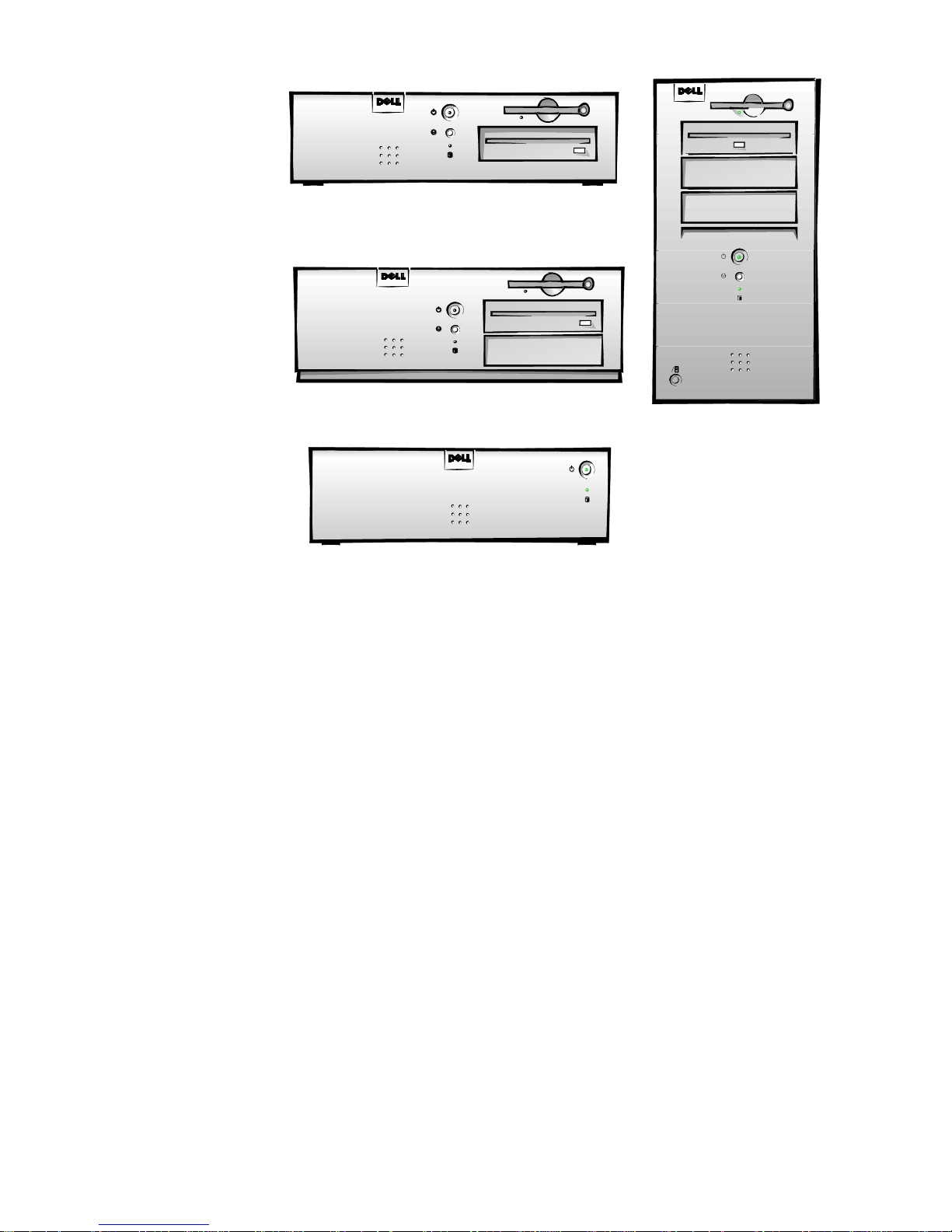
Figure 1-1. Chassis Configurations
Midsize Chassis
Low-Profile Chassis
Mini Tower Chassis
Net PC C
hassis
C
hassis Differences
The three OptiPlex GXa and the OptiPlex Net PC chassis configurations differ
primarily in the following expansion features:
Number of expansion slots available for PCI/ISA expansion cards
•
Number of available internal drive bays for EIDE/SCSI drives
•
Number of available external drive bays for diskette, CD-ROM, or tape
•
drives
Physical size and power supply types (the midsize and mini tower systems
•
use the same power supply)
NOTE: Computers with Enhanced Manageability support contain a different
system board, riser board and a power supply with a secondary winding that
provides trickle (“flea”) power for the Wakeup On LAN feature when computer
power is turned off.
Due to the physical differences in the four chassis configurations, a separate
parts removal and replacement chapter (Chapters 4 through 7) is provided for
each chassis type.
1-2 Dell OptiPlex GXa and OptiPlex NX Systems Service Manual

C
hassis Similarities
All four chassis configurations have the following similarities:
Use the same system board (OptiPlex GXa systems can use either the stan-
•
dard or EM system board; the OptiPlex NX systems use the EM system
board)
Identical operational characteristics (same BIOS, POST, memory,
•
microprocessor, external I/O ports, and so on)
Identical diagnostics, diagnostic beep codes, and diagnostic-screen error
•
messages (see Chapters 1 through 3 and Appendix A). However, the
OptiPlex NX computer has no built-in diskette drive and requires a special
setup to run diskette-based diagnostics as described in Chapter 2.
S
tandard Features
The features described in the following subsections are common to all chassis
configurations. However, some of the features differ slightly, depending on
which version of the system board is installed (standard or enhanced manageability version). Where differences occur, they are marked in the paragraph
titles.
Pentium II Microprocessor
All systems in the OptiPlex GXa and OptiPlex NX computer families incorporate the Pentium II microprocessor for improved operating speeds and overall
performance. Some of the major enhancement features of the Pentium II microprocessor include internal 16-KB data and instruction caches, internal math
coprocessor, and the MMX instruction set for high performance in complex
multimedia and communications environments. The Pentium II microprocessor
also uses a technique called Single Instruction, Multiple Data (SIMD), which
permits processing data elements in parallel for additional system performance
enhancement.
The microprocessor is physically located in a single-edge contact (SEC)
cartridge/heat sink assembly on the system board for ease of upgrading when
faster processors are available. Contact Dell Computer Corporation for information about Dell-supported microprocessor upgrades.
Secondary L2 Cache
For additional performance, the OptiPlex GXa and OptiPlex NX systems
employ a secondary cache memory subsystem with a cache memory controller
and 512 KB of pipeline-burst SRAM cache memory. The L2 cache SRAM is
located in the SEC cartridge/heat sink assembly on the system board.
System Overvi ew 1-3

Main Memory
Main memory for the OptiPlex GXa and OptiPlex NX systems ranges from a
minimum of 16 MB to a maximum of 384 MB. All main memory is
implemented using high-speed ECC and non-ECC DIMMs. One to three
DIMMs, ranging in memory capacity sizes from 16 to 128 MB, may be used to
provide a maximum memory capacity of 384 MB.
Upgradable BIOS in Flash Memory
The system BIOS is implemented in flash ROM, which allows for easy BIOS
upgrades using diskette files or files downloaded from Dell’s home page on the
World Wide Web (www.dell.com). The BIOS also incorporates the POST diagnostics that test the system each time the system is started.
EIDE Subsystem
The EIDE subsystem implemented on the system board provides two Mode-4,
DMA bus-mastered EIDE interfaces, each of which can support up to two EIDE
devices (for example, CD-ROM drive, hard-disk drive, and so on). The EIDE
controller attaches to the high-speed PCI local bus.
The primary EIDE interface (IDE1) provides support for up to two highperformance EIDE devices. The computer’s boot drive should be connected to
the primary EIDE interface.
The secondary EIDE interface (IDE2) also provides support for up to two highperformance EIDE devices, typically EIDE tape drives or CD-ROM drives.
NOTES: Any externally accessible drive bays at the front of the computer are
normally used for diskette drives, CD-ROM drives, and/or tape drives.
Hard-disk drives should be installed in the internal hard-disk drive positions
described in “Hard-Disk Drive Service Information” found later in this chapter.
The OptiPlex NX system supports only one hard-disk drive and optionally one
external diskette drive for running diskette-based diagnostics as described in
Chapter 2,“Basic Troubleshooting”.
SMART Technology
As a standard feature, OptiPlex GXa and OptiPlex NX systems are equipped
with Self-Monitoring Analysis Reporting Technology (SMART), which warns
you at system start-up if your hard-disk drive has become unreliable. This warning occurs only if you use hard-disk drives with SMART technology.
Built-In Diskette/Tape Drive Controller
The OptiPlex GXa and OptiPlex NX systems are equipped with an integrated
diskette drive controller (PC87307VUL) that can support a maximum of two
non-EIDE diskette and tape drives via a 34-pin DSKT connector located on the
system board. The low-profile chassis can accommodate only one external drive
device (diskette drive or tape drive). Other chassis configurations can accommodate two external drive devices.
1-4 Dell OptiPlex GXa and OptiPlex NX Systems Service Manual

NOTES: If the diskette drive and tape drive are both attached to the diskette
drive controller on the system board, only the diskette drive is configured in the
System Setup program as Drive A or Drive B. The tape drive will then be listed
as Not Installed (under either the Drive A or Drive B category).
The OptiPlex NX system contains an integrated controller and diskette-drive
connector but is not equipped with a diskette drive. If you run diskette-based
diagnostics, this computer requir es an external diskette drive kit as described in
Chapter 2.
Built-In SVGA Subsystem
The OptiPlex GXa and OptiPlex NX systems include a built-in highperformance 64-bit accelerated graphics port (AGP) subsystem, implemented
on the system board, which drives an external SVGA monitor. The AGP contains a dedicated bus that bypasses the PCI bus and allows for interconnection
of the video subsystem directly to the Pentium chip set for the extra high performance required for 3D video subsystems. This architecture also off-loads the
PCI bus providing greater performance for devices attached to the PCI bus.
The maximum supported resolutions include 1600 x 1200 pixels with 256 colors noninterlaced and 1024 x 768 pixels with 65,536 colors noninterlaced. The
SVGA subsystem consists of the following major components:
ATI 3D Rage Pro SVGA video controller
•
2-MB synchronous graphics random-access memory (SGRAM) video
•
memory (expandable to 4 MB via a video-memory upgrade kit)
15-hole monitor port
•
Built-In Audio Controller
The built-in audio controller is a single chip that connects to the ISA bus. The
audio controller has analog jacks for line-in and microphone input. The single
line-out output jack provides stereo output for a line-level input to an external
amplifier or drives stereo headphones. See “Technical Specifications” found
later in this chapter for audio jack input and output specifications.
Built-In Ethernet NIC Support (Optional on EM System
Board)
The OptiPlex GXa systems and Optiplex NX systems are available with or
without the built-in Ethernet NIC subsystem (optional if using the EM system
board).
The standard integrated 3Com 3C905 NIC does not support the Wakeup On
LAN feature. Wakeup On LAN capability can be provided by an optional
expansion card with a +5-VFP cable that connects to the P1 connector on the
EM riser board.
The integrated 10/100-Mbps 3Com® PCI 3C905 Ethernet NIC subsystem supports both the 10BASE-T and 100BASE-T standards. The NIC subsystem
connects to the Ethernet network through a single RJ45 connector on the back
System Overvi ew 1-5

of the computer. The RJ45 connector and the NIC interface circuitry are
mounted on the system board.
The NIC connector on the computer’s back panel has the following indicators:
A yellow activity indicator flashes when the system is transmitting or
•
receiving network data. (A high volume of network traffic may make this
indicator appear to be in a steady “on” state.)
A green link integrity indicator lights up when there is a good connection
•
between the network and the NIC. When the green indicator is off, the system is not detecting a physical connection to the network.
Network Cable Requirements
The computer’s NIC connector (RJ45) is designed for attaching to an
unshielded twisted pair (UTP) Ethernet cable. The other end of the cable connects to an RJ45 jack wall plate or to an RJ45 port on a UTP concentrator or
hub, depending on the network configuration.
Chapter 4, “Using Integrated Devices,” in the Reference and Installation Guide
provides instructions for connecting the computer to, and configuring it for use
on, an Ethernet network. For OptiPlex NX systems, refer to the online
Administrator’s Guide.
Network
Full Set of I/O Ports
For desktop connectivity, the OptiPlex GXa and OptiPlex NX systems include
the following ports:
25-hole, bidirectional parallel port with EPP/ECP and demand-mode DMA
•
support
Two Universal Serial Bus (USB) ports
•
Two 9-pin serial ports
•
Two PS/2 ports (mouse and keyboard)
•
One 15-hole video connector
•
Three audio jacks (microphone, line-in, and line-out)
•
One RJ45 Ethernet NIC connector
•
See Figures 1-3 through 1-5 for I/O port identifiers for the various chassis
configurations.
1-6 Dell OptiPlex GXa and OptiPlex NX Systems Service Manual

Universal Power Supply
The OptiPlex GXa and OptiPlex NX systems are equipped with a switchselectable (115-/230-VAC) universal power supply that can operate from
standard AC power outlets in the U.S. and all international countries. The
power supply used in the midsize and mini tower chassis configurations is a
higher-capacity power supply than that used in the low-profile and NX chassis
configurations.
Dell OptiPlex GXa systems equipped with the EM system board and all
OptiPlex NX systems have a special power supply that provides trickle (“flea”)
power to support the Wakeup On LAN feature when computer power is off.
Location of Major Components
Figure 1-2 shows the front-panel features for the four chassis types; Figures 1-3
through 1-5 show internal features of the four chassis types.
System Overvi ew 1-7
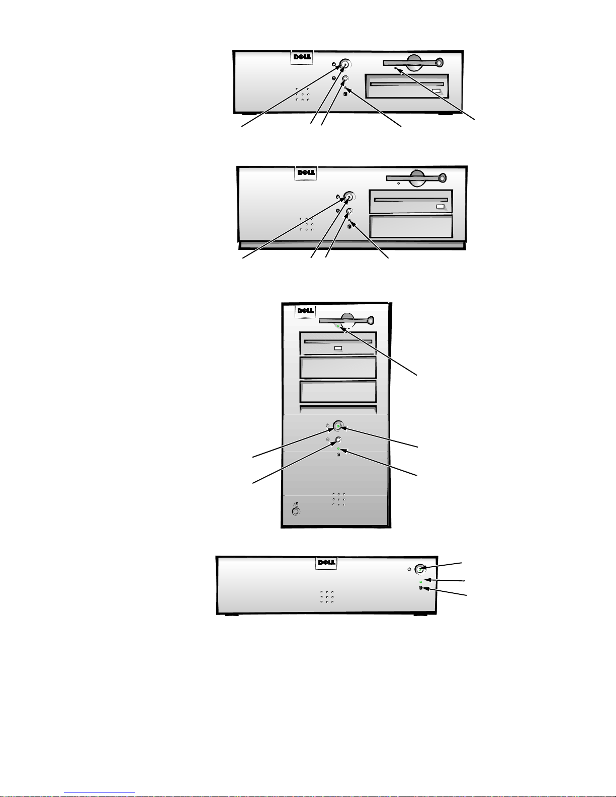
power button
power indicator
reset button
Low-Profile Chassis
hard-disk drive
access indicator
diskette-drive
access indicator
power button
power button
reset button
power indicator
reset button
Midsize Chassis
Mini Tower Chassis
hard-disk drive
access indicator
diskette-drive
access indicator
power indicator
hard-disk drive
access indicator
Figure 1-2. Front-Panel Features
1-8 Dell OptiPlex GXa and OptiPlex NX Systems Service Manual
power button
power indicator
hard-disk drive
access indicator
Net PC Chassis
padlock ring
3.5-inch diskette drive
power supply
diskette/tape drive
interface cable
hard-disk drive
interface cable
voltage
selection
switch
AC power
receptacle
security cable
slot
parallel port
connector
serial port 1
connector
mouse connector
keyboard connector
USB connectors (2)
serial port 2 connector
video connector
NIC connector (optional)
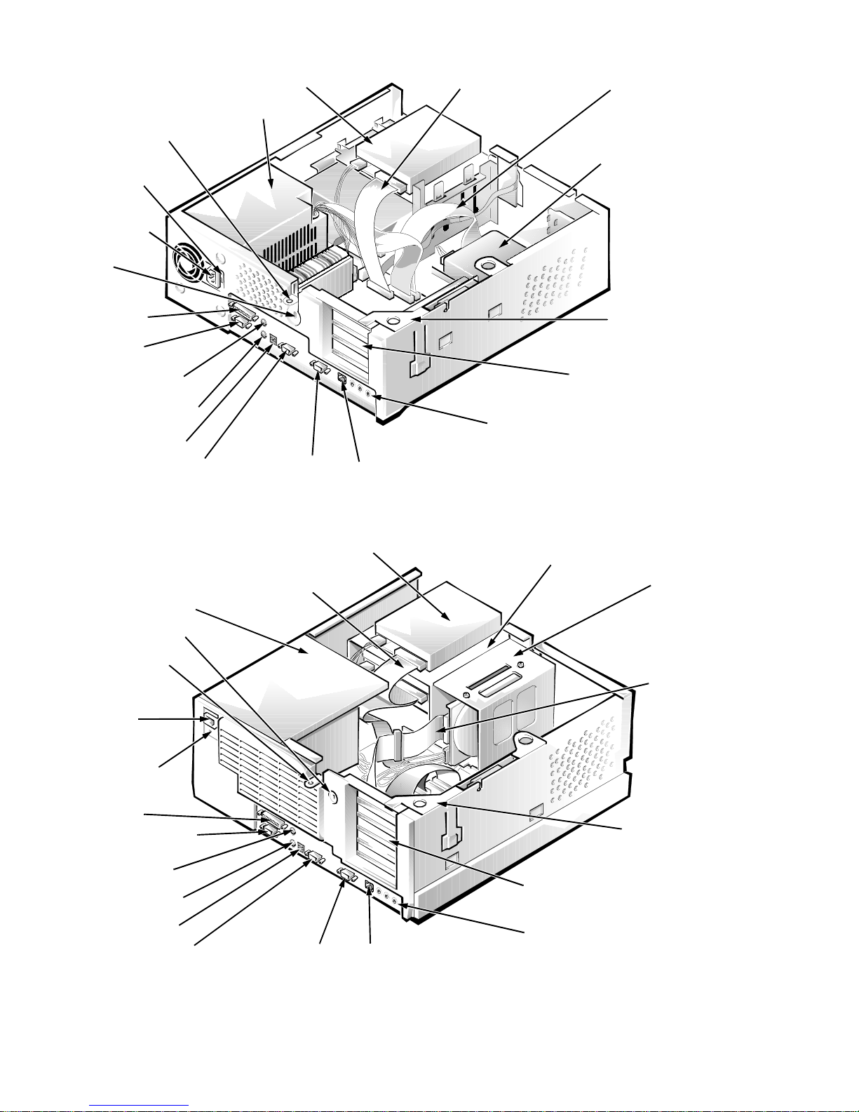
Figure 1-3. Internal View of the Low-Profile Chassis
diskette/tape drive interface cable
power supply
security cable slot
3.5-inch diskette drive
hard-disk drive
expansion-card
cage
expansion-card slots (3)
audio connectors (3)
drive cage
hard-disk drive
bracket
padlock ring
AC power
receptacle
voltage
selection switch
parallel port
connector
serial port 1 connector
mouse connector
keyboard connector
USB connectors (2)
video connectorserial port 2 connector
NIC connector (optional)
Figure 1-4. Internal View of the Midsize Chassis
hard-disk drive
interface cable
expansion-card cage
expansion-card slots (5)
audio connectors (3)
System Overvi ew 1-9
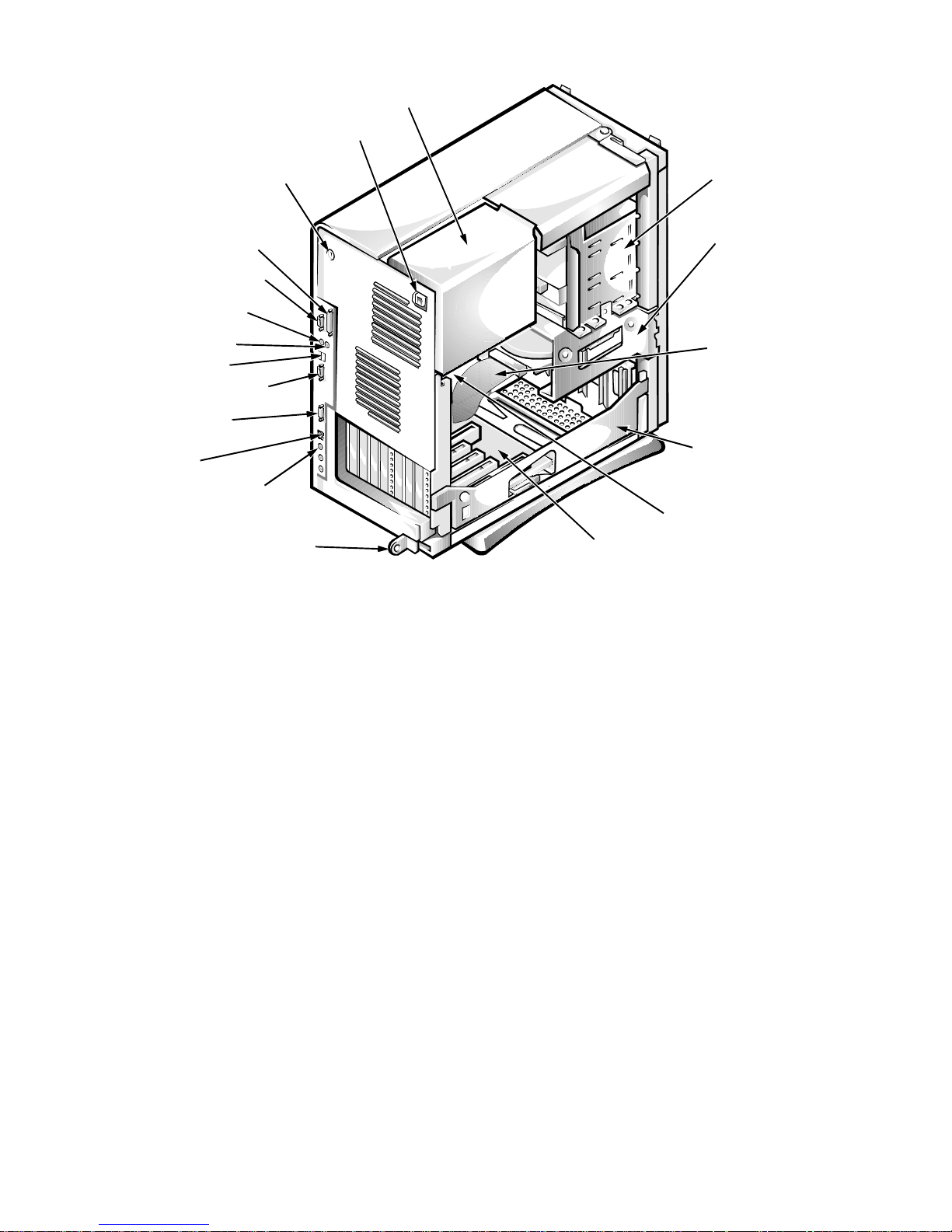
AC power receptacle
power supply
security cable slot
parallel port connector
serial port 1 connector
keyboard connector
mouse connector
USB connectors
serial port 2 connector
video connector
NIC connector
(optional)
audio connectors (3)
padlock ring
external
drive bays
hard-disk drive
bracket
interface cable
expansion-card
cage
system board
riser board
Figure 1-5. Internal View of the Mini Tower Chassis
1-10 Dell OptiPlex GXa and OptiPlex NX Systems Service Manual
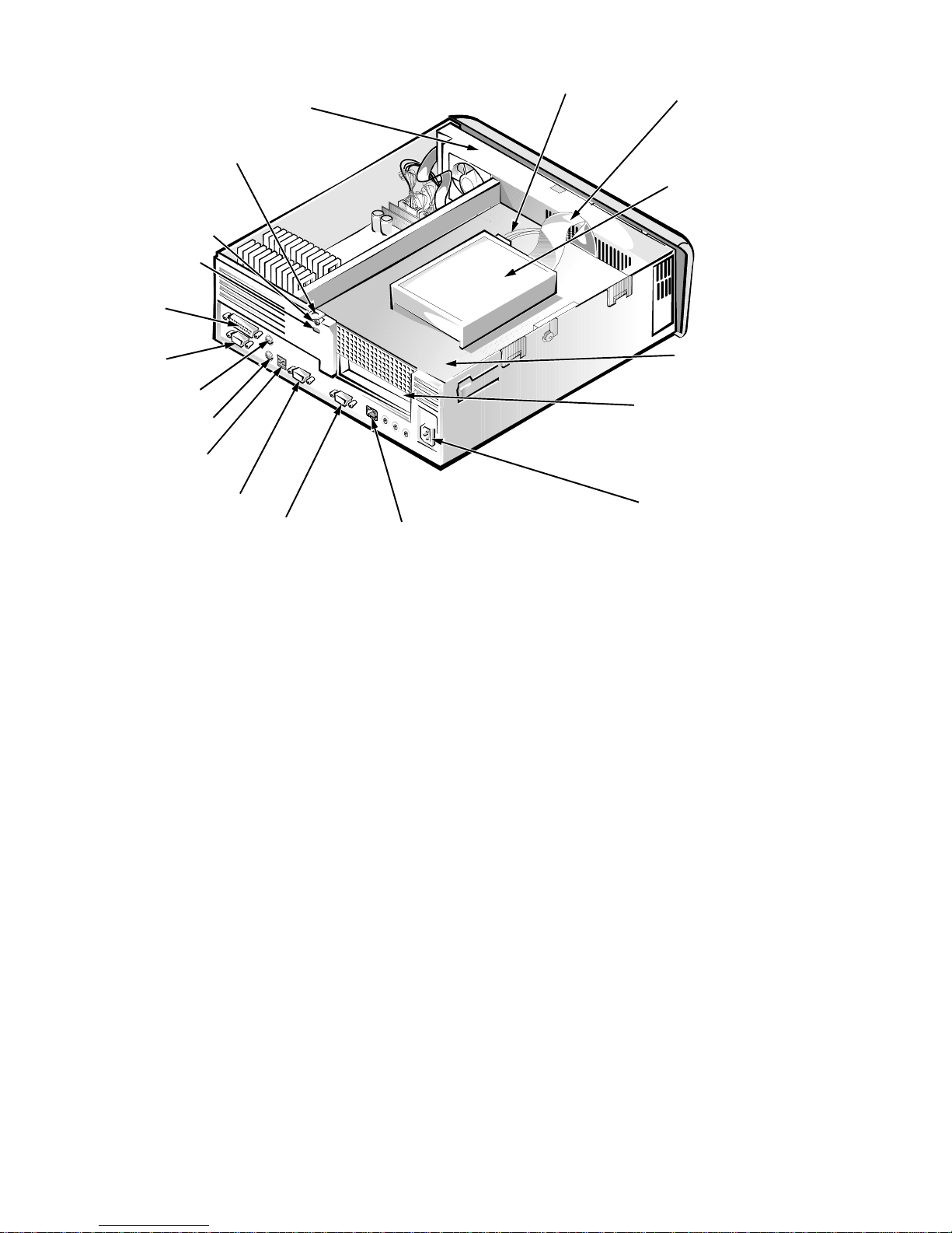
padlock ring
security access lock
security cable slot
parallel port
connector
power supply
DC power cable
EIDE cable
hard-disk drive
serial port 1
connector
mouse connector
keyboard connector
USB connectors (2)
serial port 2 connector
video connector
NIC connector (optional)
expansion-card slot
AC power
receptacle
Figure 1-6. Internal View of the Net PC Chassis
A
dvanced Expansion Features
The OptiPlex GXa systems contain advanced expansion subsystems that can
support a mixture of traditional ISA expansion cards (called le gacy cards), Plug
and Play ISA expansion cards, and PCI expansion cards.
For non-Plug and Play operating system environments, an ISA Configuration
Utility (ICU) included with the computer provides a means of avoiding
resource conflicts. Chapter 3, “Using the ISA Configuration Utility,” in the Ref-
erence and Installation Guide describes the ICU and provides instructions for
using it to configure the computer.
expansion-card
cage
In the Microsoft® Windows® 95 operating system, the functions provided by
the ICU are handled by the Device Manager, which can be accessed by
double-clicking the System icon in the Control Panel. See your Windows 95
documentation for instructions on using the Device Manager to manage
resources and resolve conflicts.
System Overvi ew 1-11
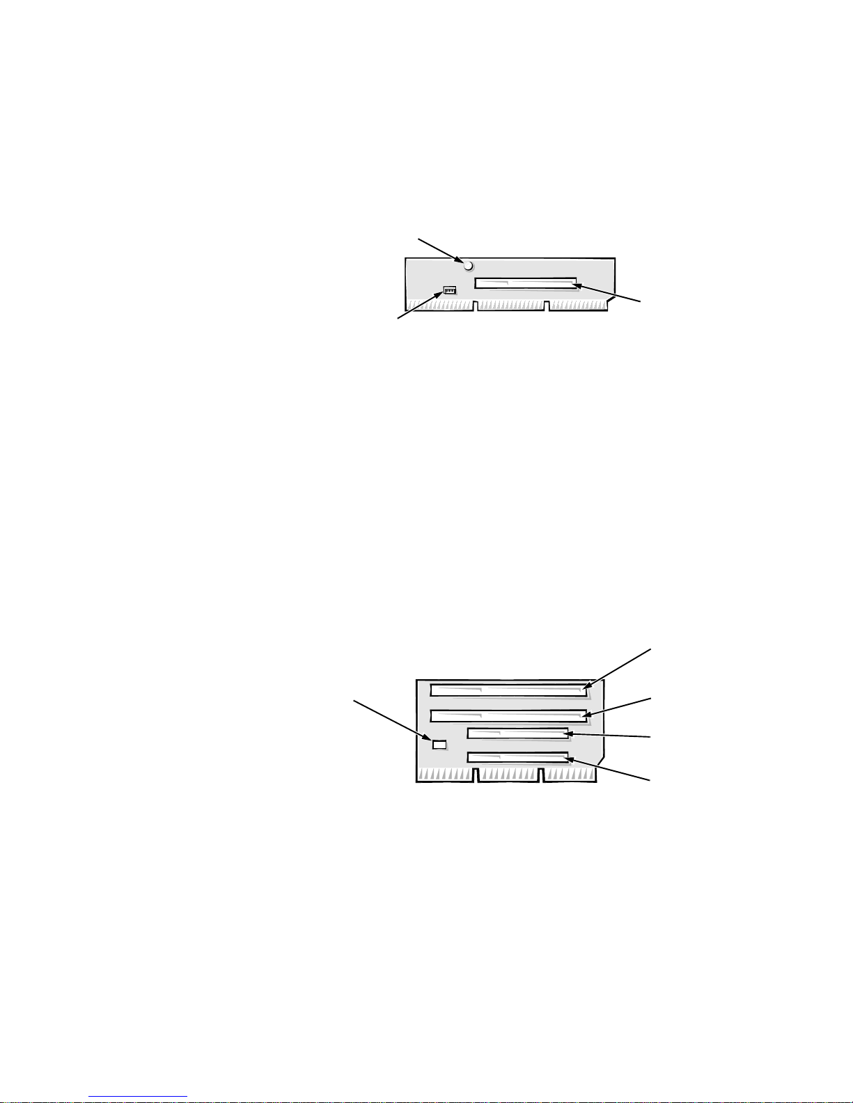
OptiPlex NX Computer’s Expansion-Card Slot
PCI1
connector
power LED
Wakeup On LAN
power connector
LED
connector
ISA2
connector
ISA1
connector
PCI2
connector
PCI1
connector
The OptiPlex NX computer has one PCI expansion-card connector on the riser
board (see Figure 1-7). The computer automatically assigns any required memory space, IRQ lines, and DMA channels to an installed PCI expansion card
during system start-up. The Wakeup On LAN power connector on the riser
board supports an optional NIC expansion card with Wakeup On LAN capability. The power LED lights up when DC power is applied to the riser board.
Figure 1-7. Riser Board for Net PC Computer
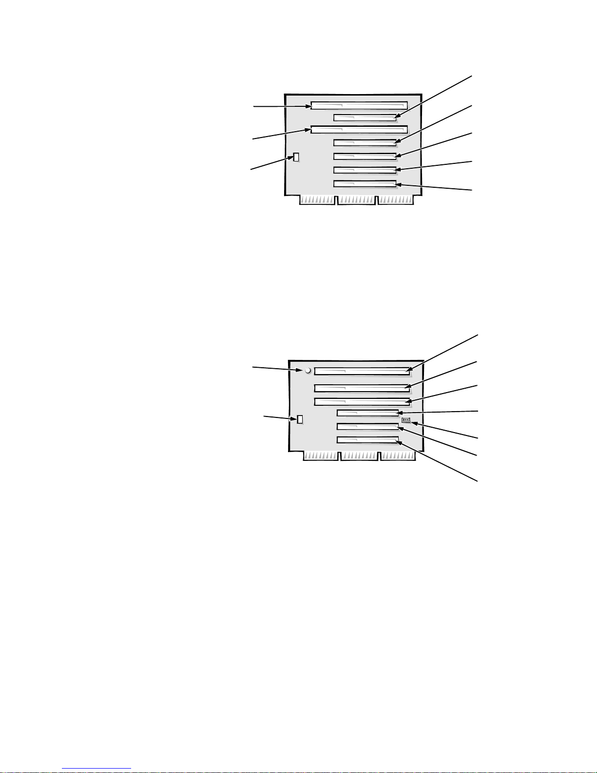
Low-Profile Computer’s Expansion-Card Slots
The OptiPlex GXa low-profile computers have three expansion-card slots. The
riser board has two ISA expansion-card connectors and two PCI expansion-card
connectors. One PCI expansion-card connector and one ISA expansion-card
connector share a single expansion-card slot, resulting in a total of three
expansion-card slots (see Figure 1-8). The low-profile computers have a passive
riser board, with no PCI-to-PCI bridge. If you have an EM version of the lowprofile computer, the riser board includes the P1 connector (for connecting the
NIC to the riser cable) and an LED (see Figure 1-8). If the LED is on, the riser is
receiving power; if off, the riser is not receiving power.
Figure 1-8. Riser Board for the Low-Profile Computer
1-12 Dell OptiPlex GXa and OptiPlex NX Systems Service Manual
HD

LED
ISA2
connector
P1
ISA1
connector
PCI2
connector
HDLED
PCI1
connector
Figure 1-9. EM Riser Board for the Low-Profile Computer
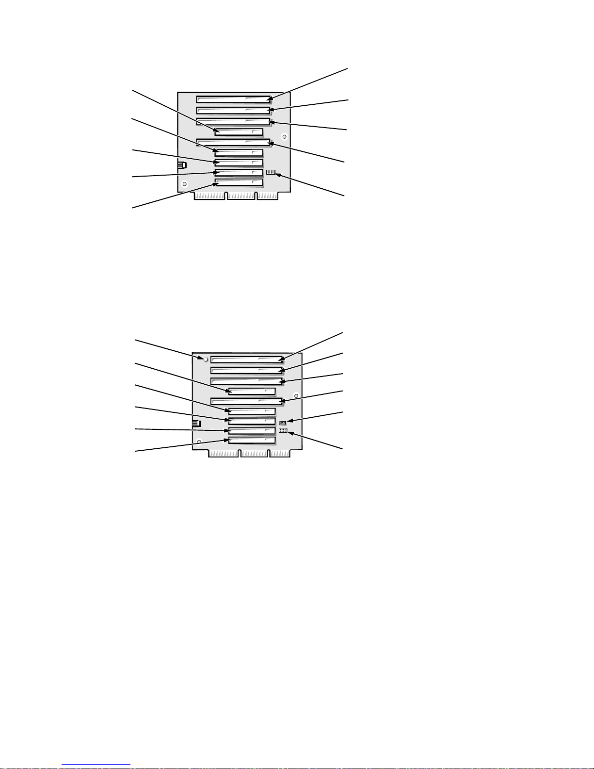
Midsize Computer’s Expansion-Card Slots
The OptiPlex GXa midsize computers have five expansion-card slots. The riser
board is offered in two options. Option 1 is a passive riser board, with no PCIto-PCI bridge. Option 1 has three ISA expansion-card connectors and three PCI
expansion-card connectors. One PCI expansion-card connector and one ISA
expansion-card connector share a single expansion-card slot, resulting in a total
of five expansion-card slots (see Figure 1-10). Option 2 is an active riser board,
with a PCI-to-PCI bridge. Option 2 has two ISA expansion-card connectors and
five PCI expansion-card connectors. Two PCI/ISA expansion-card connector
pairs each share an expansion-card slot, again resulting in a total of five
expansion-card slots (see Figure 1-11).
ISA3
connector
ISA2
connector
HDLED
connector
ISA1
connector
Figure 1-10. Riser Board for the Midsize Computer (Option 1)
PCI3
connector
PCI2
connector
PCI1
connector
System Overvi ew 1-13
ISA1
connector
ISA2
connector
PCI3
connector
PCI2
connector
PCI1
connector
PCI4
connector
PCI5
connector
HD
LED
connector
HDLED
connector
ISA3
connector
ISA2
connector
ISA1
connector
PCI3
connector
PCI2
connector
PCI1
connector
P1
LED
Figure 1-11. Riser Board for the Midsize Computer (Option 2)
If you have an EM version of the OptiPlex GXa midsize computer, the riser
board includes the P1 connector (for connecting the NIC to the riser cable) and
an LED (see Figure 1-12). If the LED is on, the riser is receiving power; if off,
the riser is not receiving power.
Figure 1-12. EM Riser Board for the Midsize Computer
Mini Tower Computer’s Expansion-Card Slots
The mini tower computers have seven expansion-card slots. The riser board has
four ISA expansion-card connectors and five PCI expansion-card connectors.
Two PCI expansion-card connectors share expansion-card slots with two ISA
connectors, resulting in a total of seven expansion-card slots (see Figure 1-13).
The riser board is active, incorporating PCI-to-PCI bridging.
1-14 Dell OptiPlex GXa and OptiPlex NX Systems Service Manual
PCI5
connector
PCI4
connector
PCI3
connector
PCI2
connector
ISA4
connector
ISA3
connector
ISA2
connector
ISA1
connector
PCI1
connector
HDLED
connector
Figure 1-13. Riser Board for the Mini Tower Computer
If you have an EM version of the minitower computer, the riser board includes
the P1 connector (for connecting the NIC to the riser cable) and an LED (see
Figure 1-14). If the LED is on, the riser is receiving power; if off, the riser is not
receiving power.
LED
PCI5
PCI4
PCI3
PCI2
PCI1
ISA4
ISA3
ISA2
ISA1
P1
HDLED
connector
Figure 1-14. EM Riser Board for the Mini Tower Computer
System Overvi ew 1-15

U
pgrade Options
The system board has various accommodations for system upgrades including:
Microprocessor upgrade
•
Main memory expansion
•
Video memory expansion
•
These upgrades are summarized in the following subsections, and installation
procedures are provided for the various chassis configurations in Chapters 4, 5,
6, and 7.
Microprocessor/L2 Cache Upgrades
On the OptiPlex GXa and OptiPlex NX systems, the microprocessor and secondary L2 cache memory are implemented in an SEC cartridge/heat sink
assembly . Upgrade to a higher-performance microprocessor is accomplished by
snapping out the old assembly and installing an upgrade assembly as higherperformance microprocessors become available.
Main Memory Expansion
The three DIMM sockets on the system board can accommodate combinations
of 16-, 32-, 64-, and 128-MB DIMMs up to a total memory capacity of
384 MB. Main memory can have either 72-bit parity (ECC) DIMMs or 64-bit
nonparity DIMMs.
Video-Memory Upgrade Option
You can upgrade video memory from 2 to 4 MB by installing an optional videomemory upgrade module in the video-memory upgrade socket on the system
board. Adding video memory increases the system’s video performance and
provides additional modes for high-resolution/expanded color applications.
NOTE: See the online System User’s Guide or Chapter 6, “Installing System
Board Options,” in the Reference and Installation Guide for additional upgrade
information.
C
omputer Service Information
The following subsections provide service-related information about the computer. Unless otherwise specified, the information applies to all chassis
configurations.
Remote Management Support Features (Optional)
For OptiPlex GXa and OptiPlex NX systems equipped with the enhanced manageability system board and power supply and an optional Wakeup On
LAN-capable network card, the following tasks may be performed by a system
administrator at a remote location.
1-16 Dell OptiPlex GXa and OptiPlex NX Systems Service Manual

Perform computer setup
•
Download and install software
•
Perform file updates
•
Perform asset-tracking functions
•
Download and run diagnostics over the network
•
Online Documentation
Dell OptiPlex GXa computers are shipped with an online System User’s Guide
(located in the Dell Accessories folder) that provides additional hardware and
software installation, configuration information, and Dell contact information.
All EM systems also contain an online Network Administrator’s Guide.
System Diagnostics
Server-based and diskette-based diagnostics are available to aid in troubleshooting all major components of the three Dell OptiPlex GXa chassis (server-based
diagnostics are available only for those systems equipped with enhanced manageability support).
The OptiPlex NX systems use server-based diagnostics, hard-disk–based
diagnostics, or the diskette-based diagnostics using an external diskette kit connected directly to the system board. See “Running the System Diagnostics” in
Chapter 2 for additional information.
System-Board Service Data
The following subsections provide service-related information about the system
board and components.
System Board
The OptiPlex GXa systems are equipped with either a standard system board or
an enhanced manageability (EM) system board. However, the OptiPlex NX systems use the EM system board only.
System Overvi ew 1-17
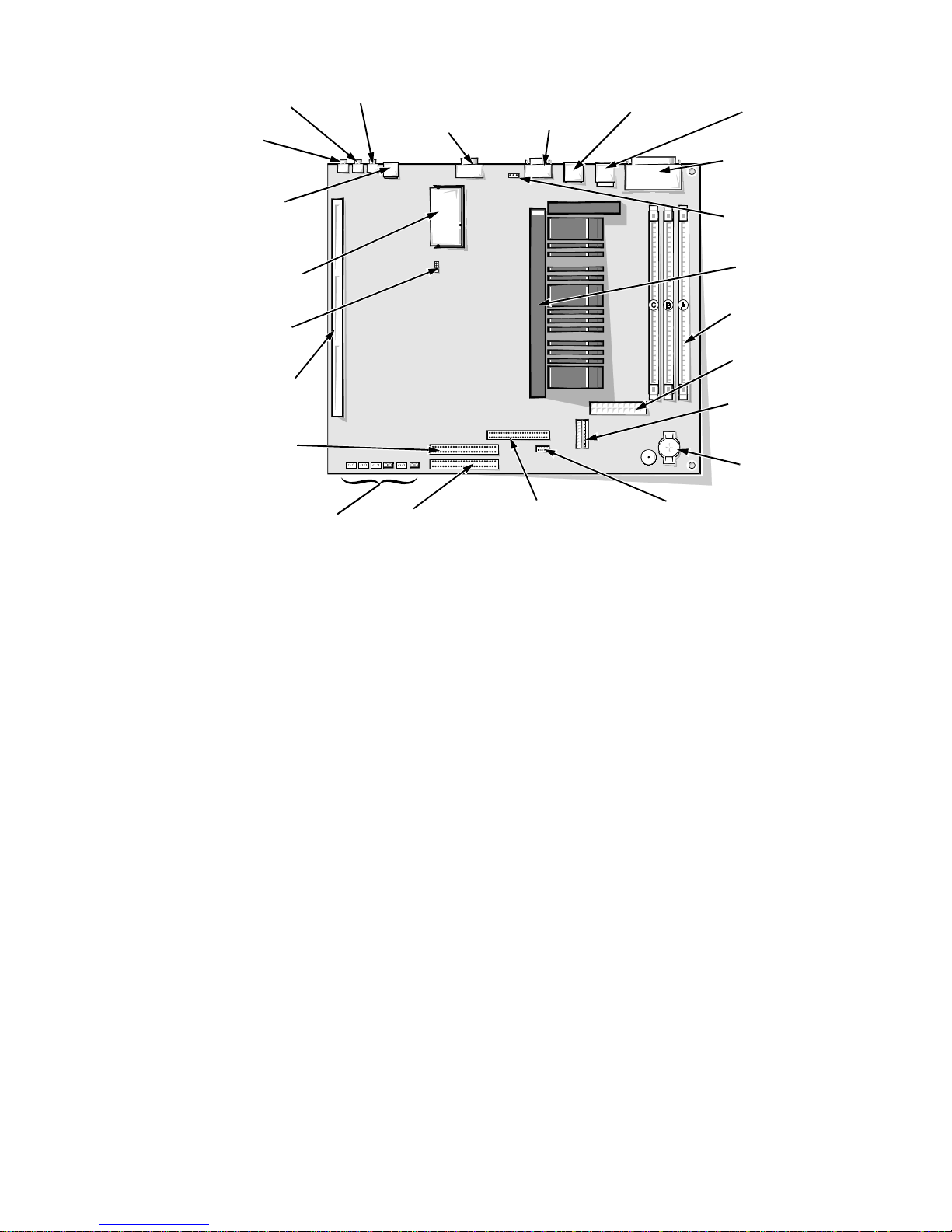
line-out jack
(LINE-OUT)
line-in jack
(LINE-IN)
Optional NIC
connector (ENET)
video-memory
upgrade socket
(VIDEO_UPGRADE)
CD-ROM audio
interface
connector (CD_IN)
riser board
connector (RISER)
secondary
EIDE interface
connector (IDE2)
microphone
jack (MIC)
video connector
(MONITOR)
serial port 2 connector
(SERIAL2)
USB connectors
(USB)
keyboard/mouse
connectors (stacked)
(KYBD/MOUSE)
parallel/serial port 1
connectors (stacked)
(PARALLEL/SERIAL1)
microprocessor fan
connector (FAN)
SEC cartridge
connector (SLOT1)
DIMM sockets (3)
(DIMM_A–DIMM_C)
main power input
connector (POWER_1)
3.3-V power input
connector (POWER_2)
battery socket
(BATTERY)
system board jumpers
Figure 1-15. System Board Components
primary EIDE
interface connector
(IDE1)
front of computer
diskette/tape drive
interface connector
(DSKT)
control panel
connector (PANEL)
1-18 Dell OptiPlex GXa and OptiPlex NX Systems Service Manual
 Loading...