

Dell OptiPlex GX620 User Manual [ja]

Dell™ OptiPlex™ GX620
Quick Reference Guide
Models DCTR, DCNE, DCSM, DCCY
www.dell.com | support.dell.com

Notes, Notices, and Cautions
NOTE: A NOTE indicates important information that helps you make better use of your computer.
NOTICE: A NOTICE indicates either potential damage to hardware or loss of data and tells you how to avoid the
problem.
CAUTION: A CAUTION indicates a potential for property damage, personal injury, or death.
Abbreviations and Acronyms
For a complete list of abbreviations and acronyms, see the "Glossary" in the
If you purchased a Dell™ n Series computer, any references in this document to Microsoft
User’s Guide
.
®
Windows®
operating systems are not applicable.
The
Quick Reference Guide, Drivers and Utilities
CD, and operating system media are optional and may not ship
with all computers.
____________________
Information in this document is subject to change without notice.
© 2005–2006 Dell Inc. All rights reserved.
Reproduction in any manner whatsoever without the written permission of Dell Inc. is strictly forbidden.
Trademarks used in this text: Dell, OptiPlex, and the DELL logo are trademarks of Dell Inc.; Microsoft and Windows are registered trademarks
of Microsoft Corporation; Intel and Pentium are registered trademarks of Intel Corporation.
Other trademarks and trade names may be used in this document to refer to either the entities claiming the marks and names or their products.
Dell Inc. disclaims any proprietary interest in trademarks and trade names other than its own.
Models DCTR, DCNE, DCSM, DCCY
September 2006 P/N N8070 Rev. A01

Contents
Finding Information . . . . . . . . . . . . . . . . . . . . . . . . . . . . . . . . 5
System Views
Mini Tower Computer — Front View
Mini Tower Computer — Back View
Desktop Computer — Front View
Desktop Computer — Back View
Small Form Factor Computer — Front View
Small Form Factor Computer — Back View
. . . . . . . . . . . . . . . . . . . . . . . . . . . . . . . . . . . 8
. . . . . . . . . . . . . . . . . . . . . 8
. . . . . . . . . . . . . . . . . . . . 10
. . . . . . . . . . . . . . . . . . . . . . 11
. . . . . . . . . . . . . . . . . . . . . . 12
. . . . . . . . . . . . . . . . 13
. . . . . . . . . . . . . . . . 14
Mini Tower, Desktop, and Small Form Factor Computers — Back-Panel Connectors
15
Ultra-Small Form Factor Computer — Front View
Ultra-Small Form Factor Computer — Side View
Ultra-Small Form Factor Computer — Back View
Removing the Computer Cover
Before You Begin
Mini Tower Computer
Desktop Computer
Small Form Factor Computer
Ultra-Small Form Factor Computer
Inside Your Computer
Mini Tower Computer
Desktop Computer
Small Form Factor Computer
Ultra-Small Form Factor Computer
. . . . . . . . . . . . . . . . . . . . . . . . . . 20
. . . . . . . . . . . . . . . . . . . . . . . . . . . . . . 20
. . . . . . . . . . . . . . . . . . . . . . . . . . . . 21
. . . . . . . . . . . . . . . . . . . . . . . . . . . . . 23
. . . . . . . . . . . . . . . . . . . . . . . . 24
. . . . . . . . . . . . . . . . . . . . . 25
. . . . . . . . . . . . . . . . . . . . . . . . . . . . . . 26
. . . . . . . . . . . . . . . . . . . . . . . . . . . . 26
. . . . . . . . . . . . . . . . . . . . . . . . . . . . . 27
. . . . . . . . . . . . . . . . . . . . . . . . 28
. . . . . . . . . . . . . . . . . . . . . 29
. . . . . . . . . . . . . 17
. . . . . . . . . . . . . . 18
. . . . . . . . . . . . . 18
Setting Up Your Computer
Solving Problems
Dell Diagnostics
System Lights
Diagnostic Lights
Beep Codes
. . . . . . . . . . . . . . . . . . . . . . . . . . . . 29
. . . . . . . . . . . . . . . . . . . . . . . . . . . . . . . . 32
. . . . . . . . . . . . . . . . . . . . . . . . . . . . . . . 32
. . . . . . . . . . . . . . . . . . . . . . . . . . . . . . . . 35
. . . . . . . . . . . . . . . . . . . . . . . . . . . . . . . . . 36
. . . . . . . . . . . . . . . . . . . . . . . . . . . . . . . . . 39
Running the Dell™ IDE Hard Drive Diagnostics
Resolving Software and Hardware Incompatibilities
®
Using Microsoft
Windows® XP System Restore . . . . . . . . . . . . . 40
. . . . . . . . . . . . . . 40
. . . . . . . . . . . 40
Contents 3

Reinstalling Microsoft® Windows® XP . . . . . . . . . . . . . . . . . . 42
Using the Drivers and Utilities CD
. . . . . . . . . . . . . . . . . . . . . . . . 44
Index . . . . . . . . . . . . . . . . . . . . . . . . . . . . . . . . . . . . . . . . . 47
4 Contents
Finding Information
NOTE: Some features may not be available for your computer or in certain countries.
NOTE: Additional information may ship with your computer.
What Are You Looking For? Find It Here
• A diagnostic program for my computer
• Drivers for my computer
• My computer documentation
• My device documentation
• Desktop System Software (DSS)
• Operating system updates and patches
• Warranty information
• Terms and Conditions (U.S only)
• Safety instructions
• Regulatory information
• Ergonomics information
• End User License Agreement
Drivers and Utilities CD (also known as the ResourceCD)
Documentation and drivers are already installed
on your computer. You can use the CD to
reinstall drivers (see page 44), run the Dell
Diagnostics (see page 33), or access your
documentation.
Readme files may be included on your CD to
provide last-minute updates about technical
changes to your computer or advanced
technical-reference material for technicians or
experienced users.
NOTE: Drivers and documentation updates can be found at support.dell.com.
NOTE: The Drivers and Utilities CD is optional and may not ship with your
computer.
Desktop System Software (DSS)
Located on the Drivers and Utilities CD and the Dell Support website at
support.dell.com.
Dell™ Product Information Guide
• How to remove and replace parts
• Specifications
• How to configure system settings
• How to troubleshoot and solve problems
User’s Guide
®
Available in the Microsoft
1
Click the
2
Click
The User’s Guide is also available on the optional Drivers and Utilities CD.
Start
button and click
User’s and system guides
Windows® XP Help and Support Center:
Help and Support.
and click
User’s guides
Quick Reference Guide 5
.

What Are You Looking For? Find It Here
• Service Tag and Express Service Code
• Microsoft Windows License Label
Service Tag and Microsoft Windows License
These labels are located on your computer.
• Use the Service Tag to identify your computer
when you use
technical support.
• Enter the Express Service Code to direct your call when contacting
technical support.
• Solutions — Troubleshooting hints and
tips, articles from technicians, online
courses, frequently asked questions
• Community — Online discussion with
other Dell customers
• Upgrades — Upgrade information for
components, such as memory, the hard
drive, and the operating system
• Customer Care — Contact information,
service call and order status, warranty, and
repair information
• Service and support — Service call status
Dell Support Website — support.dell.com
NOTE: Select your region to view the appropriate support site.
The Dell Support website provides several online tools, including:
• Troubleshooting — Hints and tips, articles from technicians, and online
courses
• Upgrades — Upgrade information for components, such as memory, the
hard drive, and the operating system
• Services and Warranties — Contact information, order status, warranty,
and repair information
• Downloads — Drivers, patches, and software updates
• User guides — Computer documentation and product specifications
and support history, service contract,
online discussions with technical support
• Reference — Computer documentation,
details on computer configuration,
product specifications, and white papers
• Downloads — Certified drivers, patches,
and software updates
• Desktop System Software (DSS) — If you
reinstall the operating system for your
computer, you should also reinstall the
DSS utility. DSS provides critical updates
for your operating system and support for
Dell™ 3.5-inch USB floppy drives, Intel
Pentium
®
M processors, optical drives,
®
and USB devices. DSS is necessary for
correct operation of your Dell computer.
This software automatically detects your
computer and operating system and
installs the updates appropriate for your
configuration.
support.dell.com
or contact
6 Quick Reference Guide

What Are You Looking For? Find It Here
• Service call status and support history
• Top technical issues for my computer
• Frequently asked questions
• File downloads
Dell Premier Support Website — premiersupport.dell.com
The Dell Premier Support website is customized for corporate, government,
and education customers. This website may not be available in certain
regions.
• Details on my computer configuration
• Service contract for my computer
• How to use Windows XP
• Documentation for my computer
• Documentation for devices (such as a
modem)
• How to reinstall my operating system
Windows Help and Support Center
1
Click the
2
Type a word or phrase that describes your problem and click the arrow icon.
3
Click the topic that describes your problem.
4
Follow the instructions on the screen.
Operating System CD
The operating system is already installed on your computer. To reinstall
your operating system, use the Operating System CD. See your online User’s
Guide for instructions.
NOTE: The operating system media is optional and may not ship with all
computers.
Start
button and click
Help and Support
.
After you reinstall your operating system, use the
optional Drivers and Utilities CD to reinstall drivers
for the devices that came with your computer.
Your operating system product key label is located
on your computer.
• Regulatory model information and chassis
type
NOTE: The color of your CD varies based on the operating system you ordered.
NOTE: The Operating System CD is optional and may not ship with your
computer.
• DCTR — Mini tower chassis
• DCNE — Desktop chassis
• DCSM — Small form factor chassis
• DCCY — Ultra-small form factor chassis
Quick Reference Guide 7
System Views
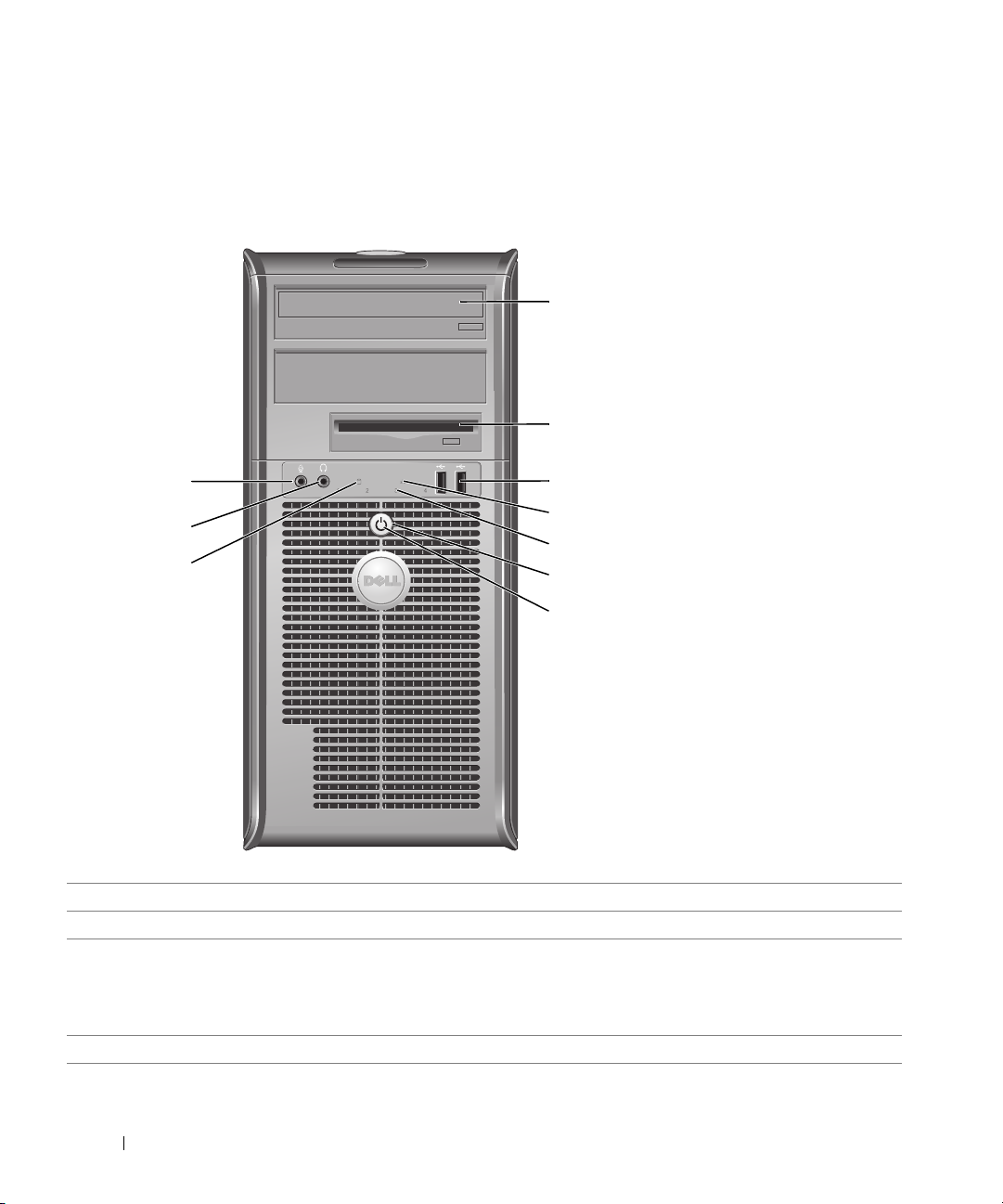
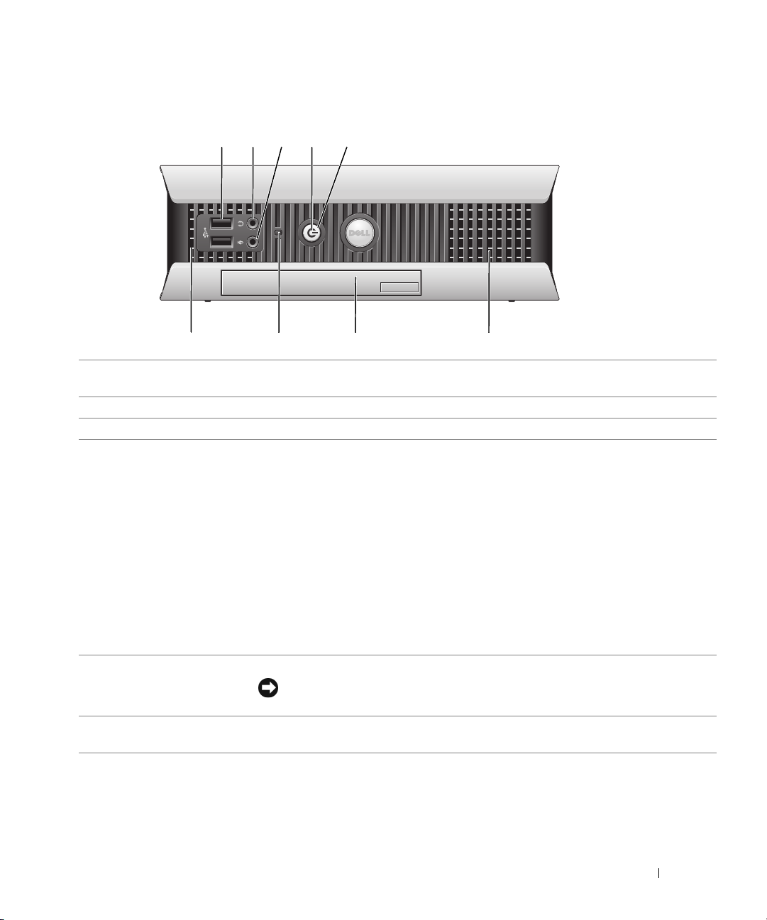
Mini Tower Computer — Front View
1
2
10
9
8
1 CD/DVD drive
2 floppy drive
3 USB 2.0 connectors (2) Connect USB devices such as a mouse, keyboard, memory key, printer, joystick, and
4 LAN indicator light
Insert a CD or DVD (if applicable) into this drive.
Insert a floppy disk into this drive.
computer speakers into either of the USB connectors.
It is recommended that you use the USB connectors on the back panel for devices that
typically remain connected, such as printers and keyboards.
This light indicates that a LAN (network) connection is established.
3
4
5
6
7
8 Quick Reference Guide

5 diagnostic lights
6 power button Press this button to turn on the computer.
7 power light The power light illuminates and blinks or remains solid to indicate different operating
8 hard-drive activity light
9 headphone connector Use the headphone connector to attach headphones and most kinds of speakers.
10 microphone connector Use the microphone connector to attach a microphone.
Use these lights to help you troubleshoot a computer problem based on the diagnostic
code. For more information, see "Diagnostic Lights" on page 36.
NOTICE: To avoid losing data, do not turn off the computer by pressing the power
button for 6 seconds or longer. Instead, perform an operating system shutdown.
NOTICE: If your operating system has ACPI enabled, when you press the power
button the computer will perform an operating system shutdown.
states:
• No light — The computer is turned off.
• Steady green — The computer is in a normal operating state.
• Blinking green — The computer is in a power-saving mode.
• Blinking or solid amber — See "Power Problems" in your online
To exit from a power-saving mode, press the power button or use the keyboard or the
mouse if it is configured as a wake device in the Windows Device Manager. For more
information about sleep modes and exiting from a power-saving mode, see "Power
Management"
See "System Lights" on page 35 for a description of power light patterns that can help
you troubleshoot problems with your computer.
This light flickers when the hard drive is in use.
in your online
User’s Guide.
User’s Guide.
Quick Reference Guide 9
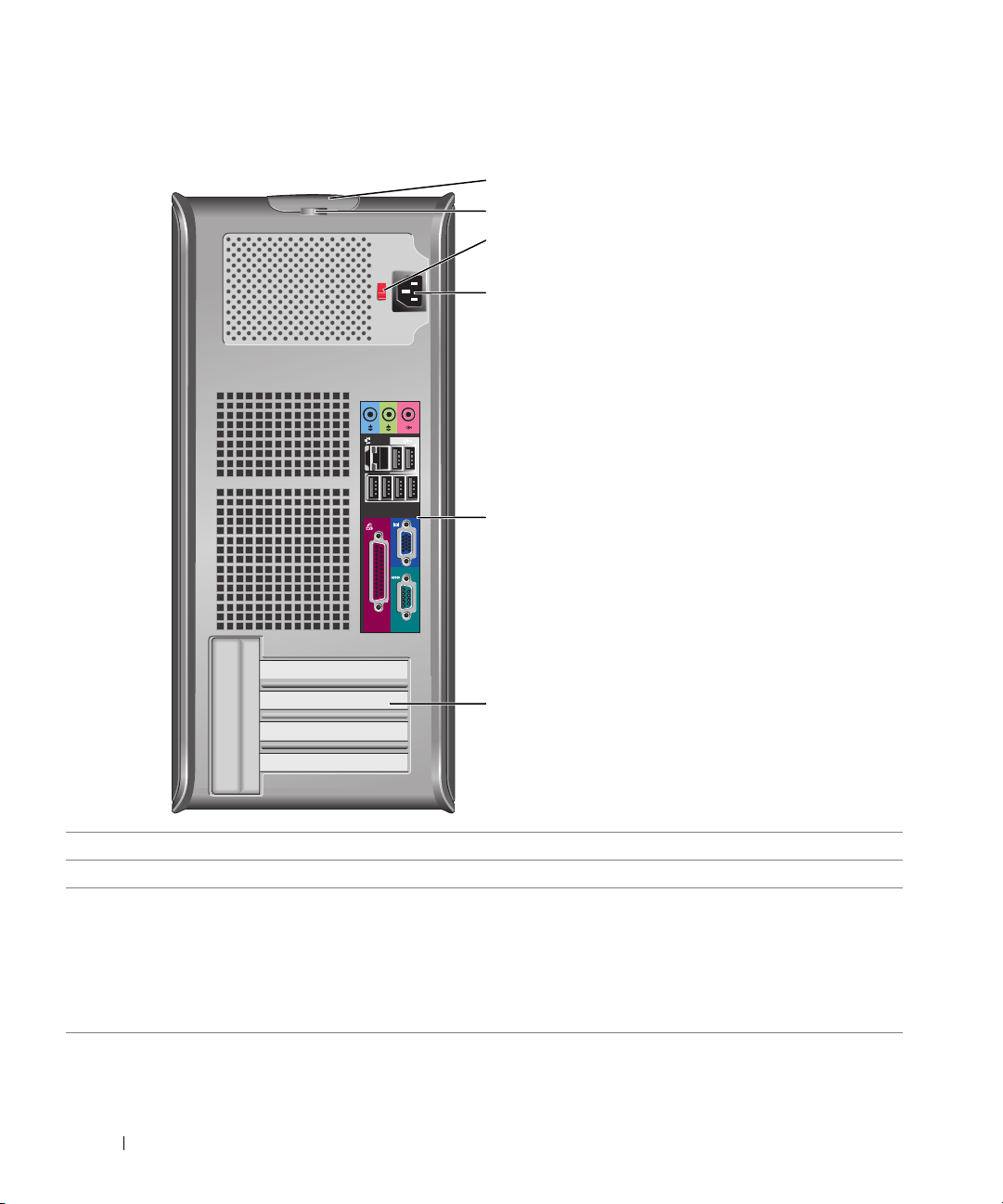
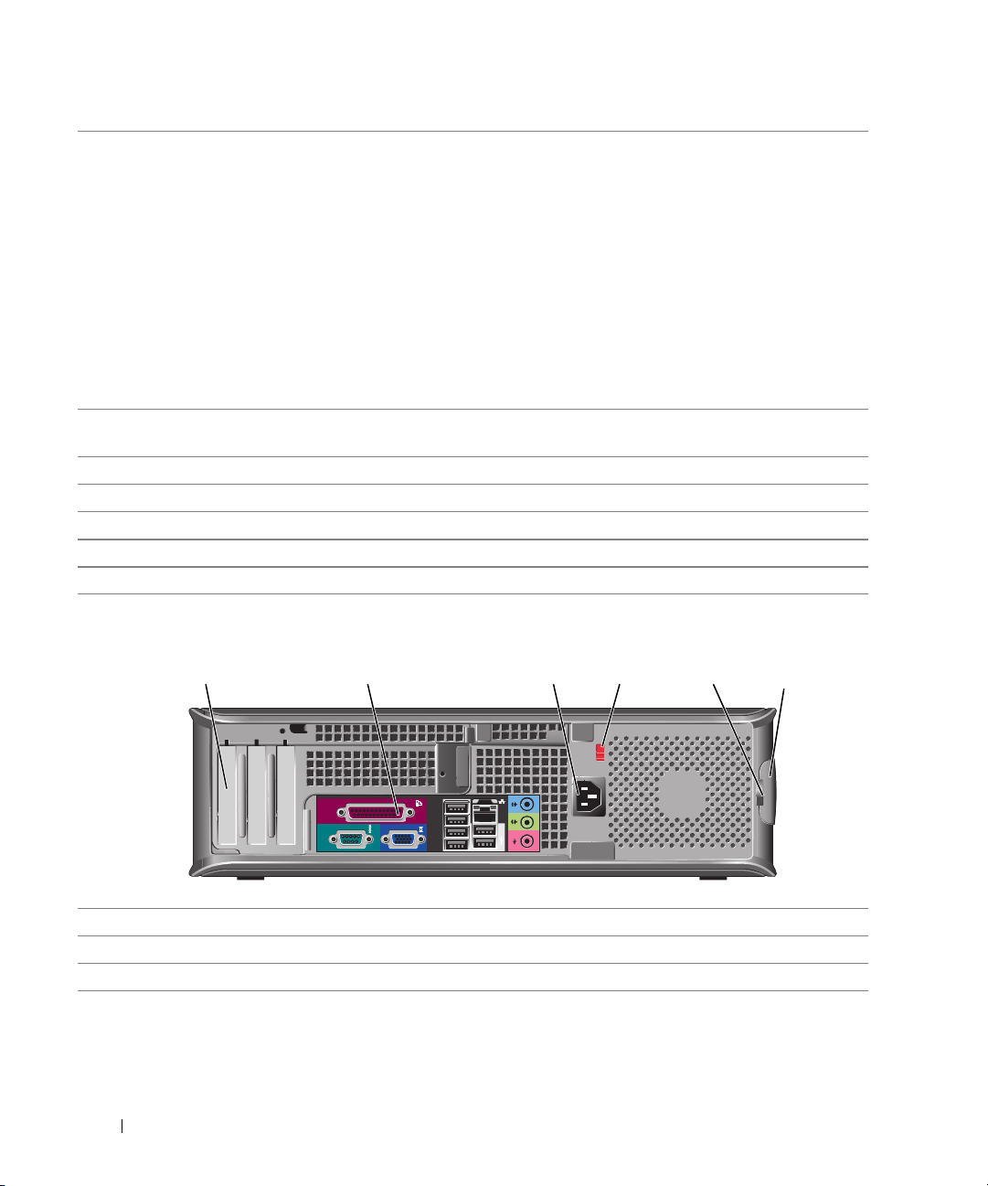
Mini Tower Computer — Back View
1
2
3
4
5
6
1
cover release latch This latch allows you to open the computer cover.
2
padlock ring Insert a padlock to lock the computer cover.
3 voltage selection switch
(may not be available on
certain computers)
Your computer is equipped with a manual voltage-selection switch.
To help avoid damaging a computer with a manual voltage-selection switch, set the
switch for the voltage that most closely matches the AC power available in your
location.
Also, ensure that your monitor and attached devices are electrically rated to operate
with the AC power available in your location.
10 Quick Reference Guide
4 power connector Insert the power cable into this connector.
5 back-panel connectors Plug serial, USB, and other devices into the appropriate connector.
6 card slots You can access connectors for any installed PCI and PCI Express cards.
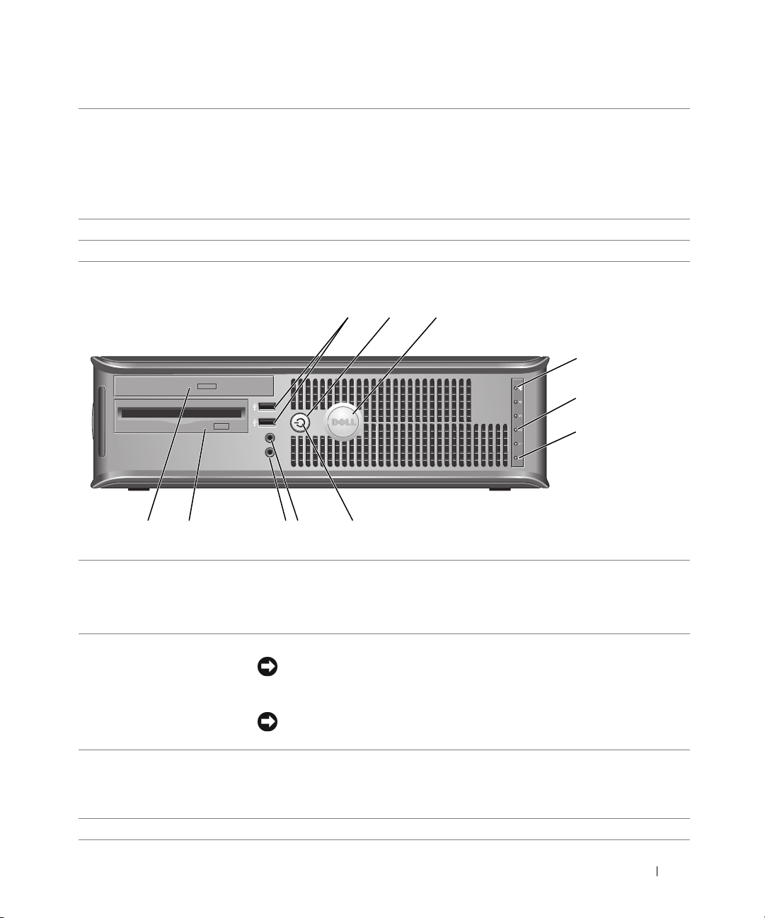
Desktop Computer — Front View
2
89
7
1 USB 2.0 connectors (2) Connect USB devices such as a mouse, keyboard, memory key, printer, joystick,
and computer speakers into either of the USB connectors.
It is recommended that you use the back USB connectors for devices that typically
remain connected, such as printers and keyboards.
2 LAN indicator light This light indicates that a LAN (network) connection is established.
3 power button Press this button to turn on the computer.
NOTICE: To avoid losing data, do not turn off the computer by pressing the
power button for 6 seconds or longer. Instead, perform an operating system
shutdown.
NOTICE: If your operating system has ACPI enabled, when you press the power
button the computer will perform an operating system shutdown.
4 Dell badge The badge can be rotated to match the orientation of your computer. To rotate
the badge, place your fingers around the outside of the badge, press firmly, and
turn the badge. You can also rotate the badge using the slot provided near the
bottom of the badge.
3
514611 10
Quick Reference Guide 11
5 power light This light turns on and blinks or remains solid to indicate different operating
states:
• No light — The computer is turned off.
• Steady green — The computer is in a normal operating state.
• Blinking green — The computer is in a power-saving mode.
• Blinking or solid amber — See "Power Problems" in your online
To exit from a power-saving mode, press the power button or use the keyboard or
the mouse if it is configured as a wake device in the Windows Device Manager. For
more information about sleep modes and exiting from a power-saving mode, see
"Power Management"
See "System Lights" on page 35 for a description of power light patterns that can
help you troubleshoot problems with your computer.
6 diagnostic lights Use these lights to help you troubleshoot a computer problem based on the
diagnostic code. For more information, see "Diagnostic Lights" on page 36.
7 hard-drive activity light This light flickers when the hard drive is in use.
8 headphone connector Use the headphone connector to attach headphones and most kinds of speakers.
9 microphone connector Use the microphone connector to attach a microphone.
10 floppy drive Insert a floppy disk into this drive.
11 CD/DVD drive Insert a CD or DVD (if applicable) into this drive.
in your online
User’s Guide.
User’s Guide
.
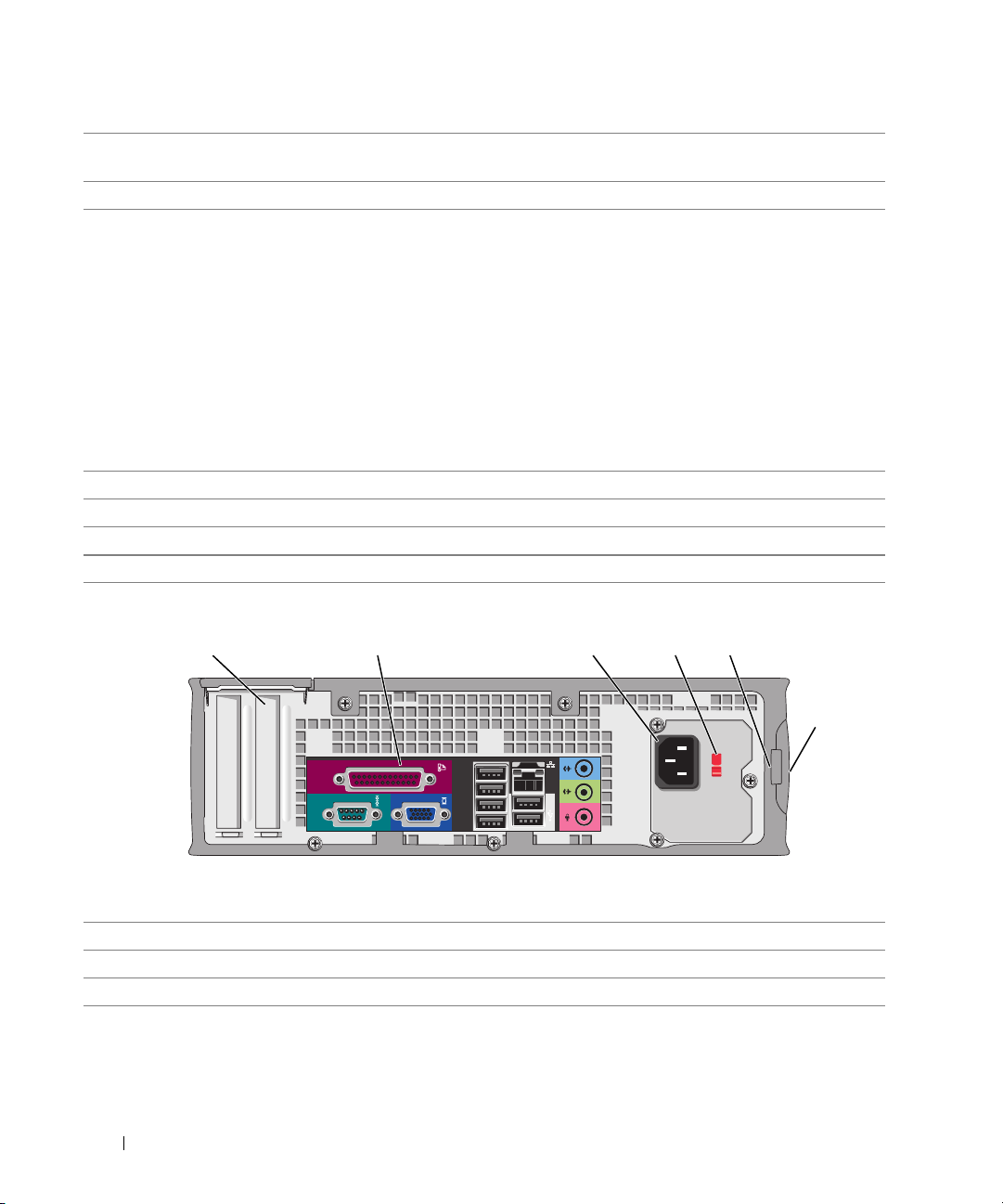
Desktop Computer — Back View
1
1 card slots You can access connectors for any installed PCI and PCI Express cards.
2 back-panel connectors Plug serial, USB, and other devices into the appropriate connector.
3 power connector Insert the power cable into this connector.
2 3 4 6
5
12 Quick Reference Guide
4 voltage selection switch
(may not be available on
certain computers)
5 padlock ring Insert a padlock to lock the computer cover.
6 cover release latch Use this latch to open the computer cover.
Your computer is equipped with a manual voltage-selection switch.
To help avoid damaging a computer with a manual voltage-selection switch, set
the switch for the voltage that most closely matches the AC power available in
your location.
Also, ensure that your monitor and attached devices are electrically rated to
operate with the AC power available in your location.
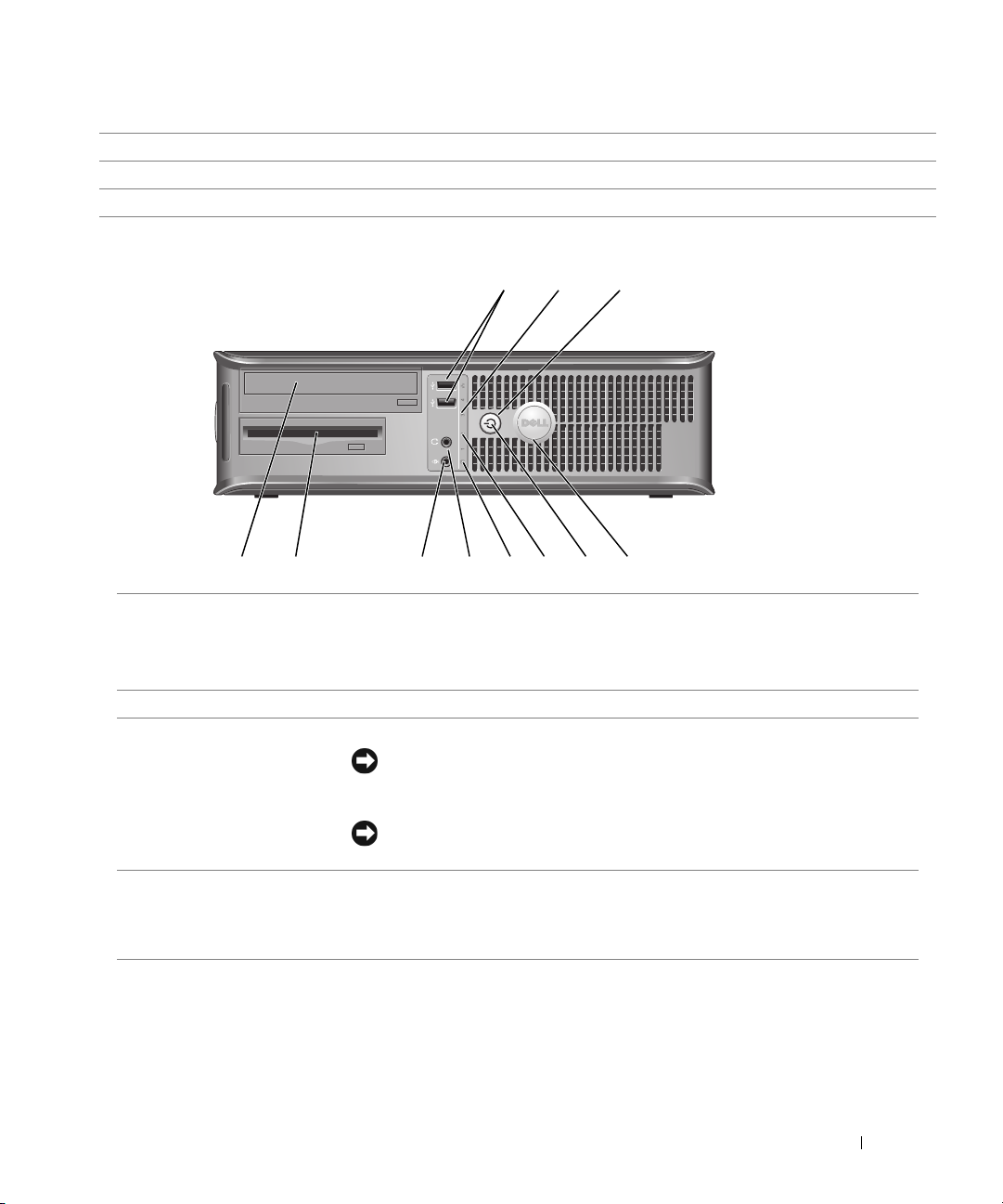
Small Form Factor Computer — Front View
2
1
11 10
1 USB 2.0 connectors (2) Connect USB devices such as a mouse, keyboard, memory key, printer, joystick,
and computer speakers into either of the USB connectors.
It is recommended that you use the back USB connectors for devices that typically
remain connected, such as printers and keyboards.
2 power button Press this button to turn on the computer.
3 Dell badge The badge can be rotated to match the orientation of your computer. To rotate
the badge, place fingers around the outside of the badge, press firmly, and turn the
badge. You can also rotate the badge using the slot provided near the bottom of
the badge.
4 LAN indicator light This light indicates that a LAN (network) connection is established.
89
NOTICE: To avoid losing data, do not turn off the computer by pressing the
power button for 6 seconds or longer. Instead, perform an operating system
shutdown.
NOTICE: If your operating system has ACPI enabled, when you press the power
button the computer will perform an operating system shutdown.
7
3
4
5
6
Quick Reference Guide 13
5 diagnostic lights Use the lights to help you troubleshoot a computer problem based on the
diagnostic code. For more information, see "Diagnostic Lights" on page 36.
6 hard-drive activity light This light flickers when the hard drive is in use.
7 power light Turns on and blinks or remains solid to indicate different operating states:
• No light — The computer is turned off.
• Steady green — The computer is in a normal operating state.
• Blinking green — The computer is in a power-saving mode.
• Blinking or solid amber — See "Power Problems" in your online
To exit from a power-saving mode, press the power button or use the keyboard or
the mouse if it is configured as a wake device in the Windows Device Manager. For
more information about sleep modes and exiting from a power-saving mode, see
"Power Management" in your online User’s Guide.
See "System Lights" on page 35 for a description of power light patterns that can
help you troubleshoot problems with your computer.
8 headphone connector Use the headphone connector to attach headphones and most kinds of speakers.
9 microphone connector Use the microphone connector to attach a microphone.
10 floppy drive Insert a floppy disk into this drive.
11 CD/DVD drive Insert a CD or DVD (if applicable) into this drive.
User’s Guide
.
Small Form Factor Computer — Back View
51 2 3 4
1 card slots You can access connectors for any installed PCI and PCI Express cards.
2 back-panel connectors Plug serial, USB, and other devices into the appropriate connector.
3 power connector Connect the power cable to this connector.
14 Quick Reference Guide
6
4 voltage selection switch
(may not be available on
certain computers)
5 padlock ring Insert a padlock to lock the computer cover.
6 cover release latch Use this latch to open the computer cover.
Your computer is equipped with a manual voltage-selection switch.
To help avoid damaging a computer with a manual voltage-selection switch, set
the switch for the voltage that most closely matches the AC power available in
your location.
Also, ensure that your monitor and attached devices are electrically rated to
operate with the AC power available in your location.
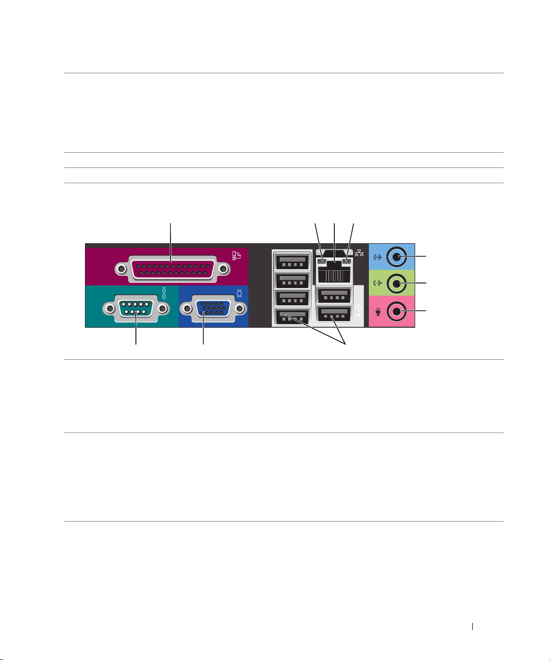
Mini Tower, Desktop, and Small Form Factor Computers — Back-Panel Connectors
13
10 9 8
1
parallel connector Connect a parallel device, such as a printer, to the parallel connector. If you have a
USB printer, plug it into a USB connector.
24
5
6
7
NOTE: The integrated parallel connector is automatically disabled if the computer
detects an installed card containing a parallel connector configured to the same
address. For more information, see "System Setup Options" in your online User’s
Guide.
link integrity light • Green — A good connection exists between a 10-Mbps network and the
2
computer.
• Orange — A good connection exists between a 100-Mbps network and the
computer.
• Yellow — A good connection exists between a 1-Gbps (or 1000-Mbps) network
and the computer.
• Off — The computer is not detecting a physical connection to the network.
Quick Reference Guide 15

3
network adapter
connector
To attach your computer to a network or broadband device, connect one end of a
network cable to either a network jack or your network or broadband device. Connect
the other end of the network cable to the network adapter connector on the back
panel of your computer. A click indicates that the network cable has been securely
attached.
NOTE: Do not plug a telephone cable into the network connector.
On computers with a network adapter card, use the connector on the card.
It is recommended that you use Category 5 wiring and connectors for your network.
If you must use Category 3 wiring, force the network speed to 10 Mbps to ensure
reliable operation.
4
network activity light This light flashes a yellow light when the computer is transmitting or receiving
network data. A high volume of network traffic may make this light appear to be in a
steady "on" state.
5
line-in connector Use the blue line-in connector to attach a record/playback device such as a cassette
player, CD player, or VCR.
On computers with a sound card, use the connector on the card.
6
line-out connector Use the green line-out connector to attach headphones and most speakers with
integrated amplifiers.
On computers with a sound card, use the connector on the card.
7
microphone connector Use the pink microphone connector to attach a personal computer microphone for
voice or musical input into a sound or telephony program.
On computers with a sound card, the microphone connector is on the card.
8
USB 2.0 connectors (6)
9
video connector Plug the cable from your VGA-compatible monitor into the blue connector.
Connect USB devices such as a mouse, keyboard, memory key, printer, joystick,
and computer speakers into any of the USB connectors.
NOTE: If you purchased an optional graphics card, this connector will be covered by
a cap. Connect your monitor to the connector on the graphics card. Do not remove
the cap.
NOTE: If you are using a graphics card that supports dual monitors, use the y-cable
that came with your computer.
serial connector Connect a serial device, such as a handheld device, to the serial port. The default
10
designations are COM1 for serial connector 1 and COM2 for serial connector 2.
For more information, see "System Setup Options" in your online
User’s Guide
.
16 Quick Reference Guide
Ultra-Small Form Factor Computer — Front View
1234 5
896
1 USB connectors (2) Connect USB devices such as a mouse, keyboard, memory key, printer, joystick, and
computer speakers into either of the USB connectors.
2 headphone connector Attach headphones to this connector.
3 microphone connector Attach a microphone to this connector.
4 power light The power light illuminates and blinks or remains solid to indicate different operating
states:
• No light — The computer is turned off.
• Steady green — The computer is in a normal operating state.
• Blinking green — The computer is in a power-saving mode.
• Blinking or solid yellow— See "Power Problems" in your online
To exit from a power-saving mode, press the power button or use the keyboard or the
mouse if it is configured as a wake device in the Windows Device Manager. For more
information about sleep modes and exiting from a power-saving mode, see "Power
Management"
See "System Lights" on page 35 for a description of power light patterns that can help
you troubleshoot problems with your computer.
5 power button Press this button to turn on the computer.
NOTICE: To avoid losing data, do not use the power button to turn off the computer.
Instead, perform a Microsoft
6 vents The vents allow air to flow through your computer. To ensure proper ventilation, do
not block these cooling vents.
7
in your online
User’s Guide
.
®
Windows® shutdown.
User’s Guide
.
Quick Reference Guide 17
7 module bay Install a D-module CD/DVD drive, second hard drive, or floppy drive in the module
bay.
8 hard-drive access light The hard-drive access light is on when the computer reads data from or writes data to
the hard drive. The light might also be on when devices such as your CD player are
operating.
9 vents The vents allow air to flow through your computer. To ensure proper ventilation, do
not block these cooling vents.
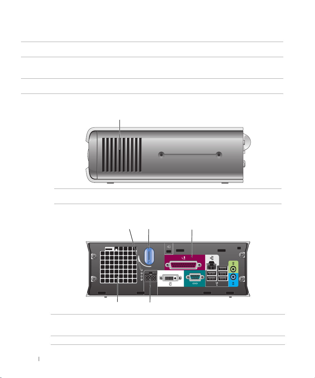
Ultra-Small Form Factor Computer — Side View
1
1 vents The vents, which are on each side of the computer, allow air to flow through your
computer. To ensure proper ventilation, do not block these cooling vents.
Ultra-Small Form Factor Computer — Back View
1 diagnostic lights Use the lights to help you troubleshoot a computer problem based
2 computer cover release knob Rotate this knob in a clockwise direction to remove the cover.
18 Quick Reference Guide
231
5
4
on the diagnostic code. For more information, see "Diagnostic
Lights" on page 36.
3 back-panel connectors See the following subsection, "Ultra-Small Form Factor Computer
— Back-Panel Connectors," for information about the connectors
on the back panel of your computer.
4 power connector Connect the power cable to this connector.
5 vents The vents allow air to flow through your computer. To ensure proper
ventilation, do not block these cooling vents.
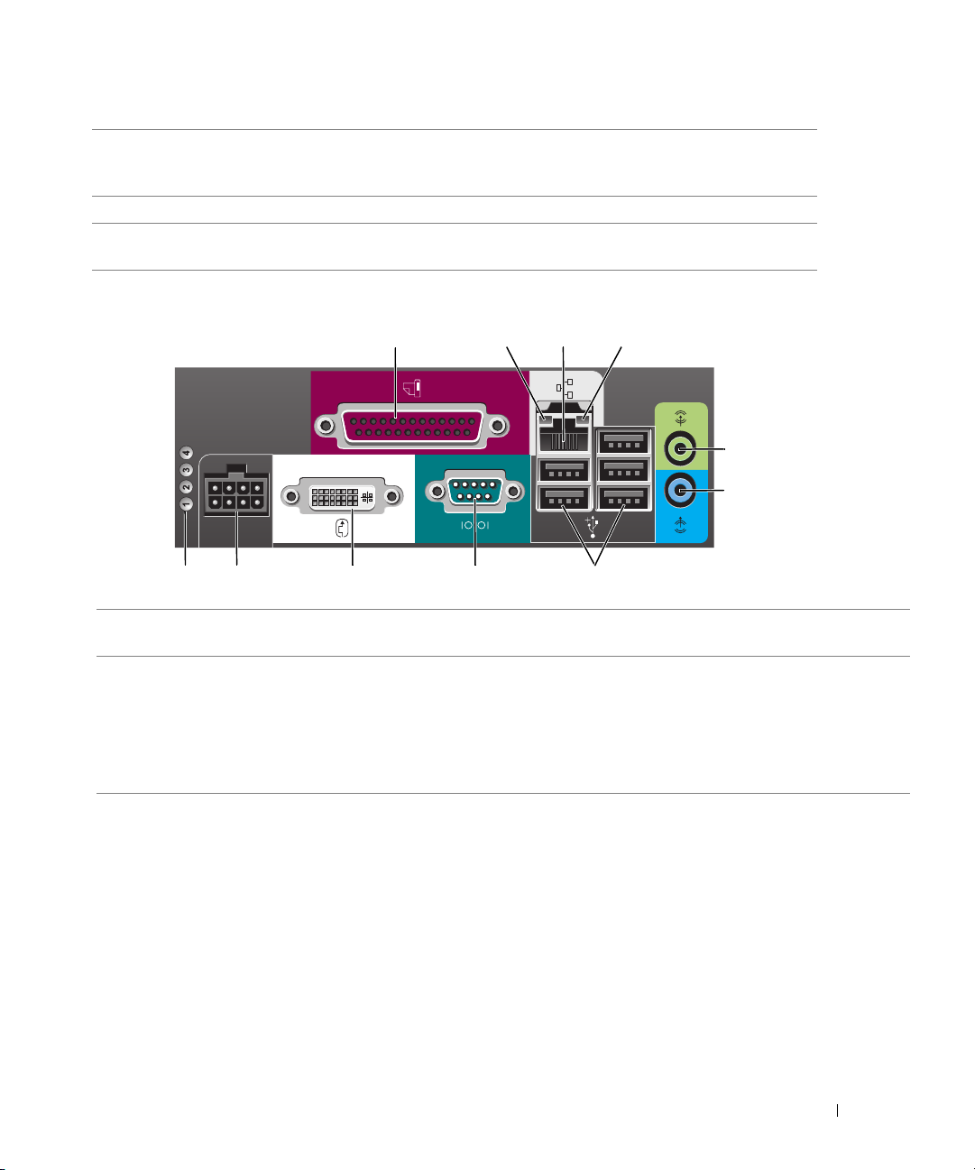
Ultra-Small Form Factor Computer — Back-Panel Connectors
2134
5
6
10 7811
1 parallel connector Connect a parallel device, such as a printer, to the parallel connector. If you have a USB
2 link integrity light
9
printer, plug it into a USB connector.
• Green — A good connection exists between a 10-Mbps network and the computer.
• Orange — A good connection exists between a 100-Mbps network and the computer.
• Yellow — A good connection exists between a 1000-Mbps (1-Gbps) network and the
computer.
• Off — The computer is not detecting a physical connection to the network or the
network controller is turned off in system setup.
Quick Reference Guide 19
3 network adapter
connector
4 network activity light The amber light flashes when the computer is transmitting or receiving network data. A
5 line-out connector Use the green line-out connector to attach an amplified speaker set.
6 line-in connector Use the blue line-in connector to attach a record/playback device such as a cassette
7 USB connectors (5) Connect USB devices such as a mouse, keyboard, printer, joystick, and computer
8 serial connector Connect a serial device, such as a handheld device, to the serial connector.
9 video connector If you have a DVI-compatible monitor, plug the cable from your monitor into the white
10 power connector Connect the power cable to this connector.
11 diagnostic lights See "Diagnostic Lights" on page 36 for a description of light codes that can help you
Attach the UTP cable to an RJ45 jack wall plate or to an RJ45 port on a UTP
concentrator or hub, and press the other end of the UTP cable into the network adapter
connector until the cable snaps securely into place.
It is recommended that you use Category 5 wiring and connectors for networks.
high volume of network traffic may make this light appear to be in a steady "on" state.
player, CD player, or VCR.
speakers into any of the USB connectors.
connector on the back panel.
If you have a VGA monitor, see "Connecting a VGA Monitor" in your online User’s
Guide.
troubleshoot problems with your computer.
Removing the Computer Cover
CAUTION: Before you begin any of the procedures in this section, follow the safety instructions in the
Product Information Guide.
CAUTION: To guard against electrical shock, always unplug your computer from the electrical outlet
before removing the cover.
Before You Begin
NOTICE: To avoid losing data, save and close any open files and exit any open programs before you turn
off your computer.
1
Shut down the operating system:
a
Save and close any open files, exit any open programs, click the
click
Turn Off Computer
b
In the
Turn off computer
The computer turns off after the operating system shutdown process finishes.
2
Ensure that the computer and any attached devices are turned off. If your computer and
attached devices did not automatically turn off when you shut down your operating system,
turn them off now.
20 Quick Reference Guide
.
window, click
Tur n o ff
Start
button, and then
.

Before Working Inside Your Computer
Use the following safety guidelines to help protect your computer from potential damage and to
help ensure your own personal safety.
CAUTION: Before you begin any of the procedures in this section, follow the safety instructions in the
Product Information Guide.
NOTICE: Only a certified service technician should perform repairs on your computer. Damage due to
servicing that is not authorized by Dell is not covered by your warranty.
NOTICE: When you disconnect a cable, pull on its connector or on its strain-relief loop, not on the cable
itself. Some cables have a connector with locking tabs; if you are disconnecting this type of cable, press
in on the locking tabs before you disconnect the cable. As you pull connectors apart, keep them evenly
aligned to avoid bending any connector pins. Also, before you connect a cable, ensure that both
connectors are correctly oriented and aligned.
To avoid damaging the computer, perform the following steps before you begin working inside
the computer.
1
Turn off your computer if it is not already turned off.
NOTICE: To disconnect a network cable, first unplug the cable from your computer and then unplug it
from the network wall jack.
2
Disconnect any telephone or telecommunication lines from the computer.
3
Disconnect your computer and all attached devices from their electrical outlets, and then
press the power button to ground the system board.
4
Remove the computer stand, if it is attached.
CAUTION: To guard against electrical shock, always unplug your computer from the electrical outlet
before removing the cover.
NOTICE: Before touching anything inside your computer, ground yourself by touching an unpainted
metal surface, such as the metal at the back of the computer. While you work, periodically touch an
unpainted metal surface to dissipate any static electricity that could harm internal components.
Mini Tower Computer
NOTICE: Before touching anything inside your computer, ground yourself by touching an unpainted
metal surface. While you work, periodically touch an unpainted metal surface to dissipate any static
electricity that could harm internal components.
1
Follow the procedures in "Before You Begin" on page 20.
2
If you have installed a padlock through the padlock ring on the back panel, remove the
padlock.
3
Lay the computer on its side as shown in the following illustration.
4
Slide the cover release latch back as you lift the cover.
Quick Reference Guide 21
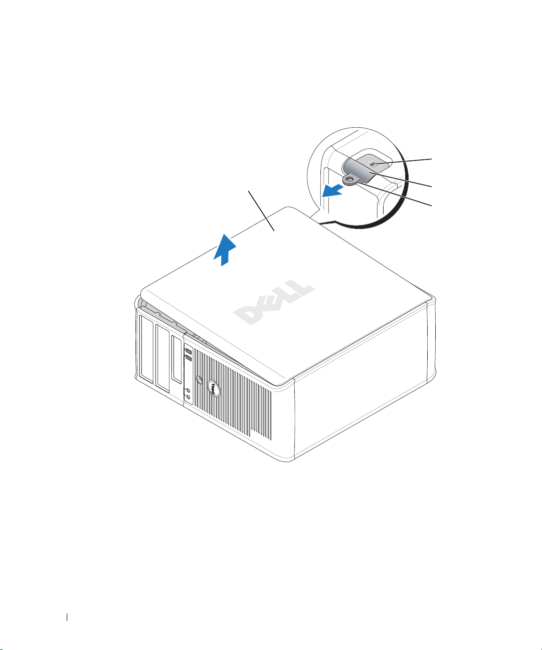
5
Grip the sides of the computer cover and pivot the cover up using the bottom hinge tabs as
leverage points.
6
Remove the cover from the hinge tabs and set it aside on a soft non-abrasive surface.
1
2
3
4
1
2
3
22 Quick Reference Guide
1
security cable slot
2
cover release latch
3
padlock ring
4
computer cover
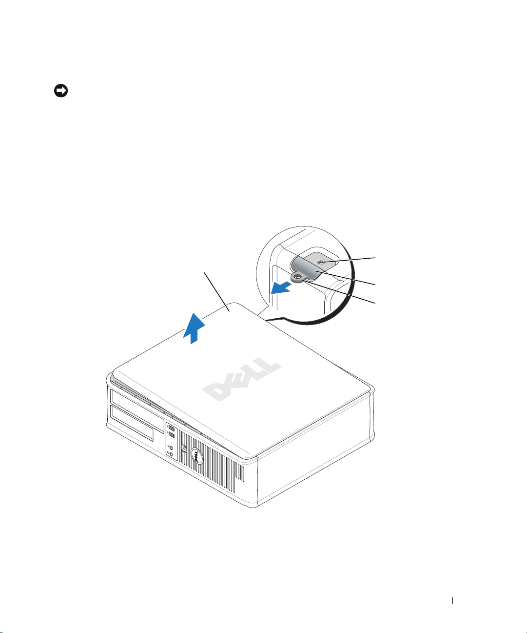
Desktop Computer
NOTICE: Before touching anything inside your computer, ground yourself by touching an unpainted
metal surface. While you work, periodically touch an unpainted metal surface to dissipate any static
electricity that could harm internal components.
1
Follow the procedures in "Before You Begin" on page 20.
2
If you have installed a padlock through the padlock ring on the back panel, remove the padlock.
3
Slide the cover release latch back as you lift the cover.
4
Grip the sides of the computer cover and pivot the cover up using the bottom hinge tabs as
leverage points.
5
Remove the cover from the hinge tabs and set it aside on a clean, non-abrasive surface.
1
4
2
3
1
security cable slot
2
cover release latch
3
padlock ring
4
computer cover
Quick Reference Guide 23
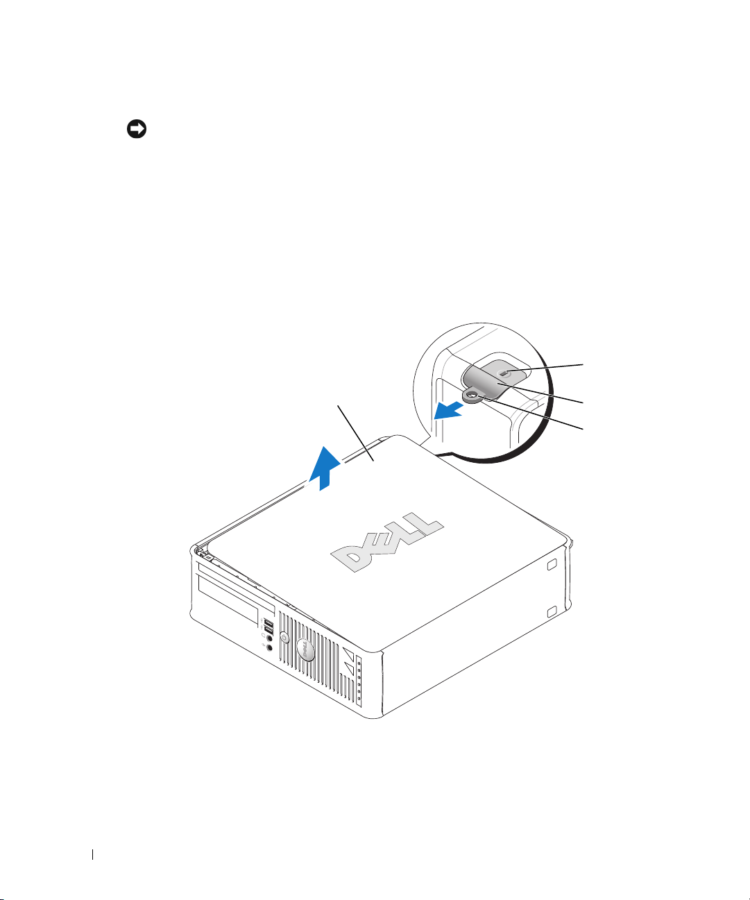
Small Form Factor Computer
NOTICE: Before touching anything inside your computer, ground yourself by touching an unpainted
metal surface. While you work, periodically touch an unpainted metal surface to dissipate any static
electricity that could harm internal components.
1
Follow the procedures in "Before You Begin" on page 20.
2
If you have installed a padlock through the padlock ring on the back panel, remove the padlock.
3
Slide the cover release latch back as you lift the cover.
4
Grip the sides of the computer cover and pivot the cover up using the bottom hinge tabs as
leverage points.
5
Remove the cover from the hinge tabs and set it aside on a clean, non-abrasive surface.
1
4
1
security cable slot
2
cover release latch
3
padlock ring
4
computer cover
2
3
24 Quick Reference Guide
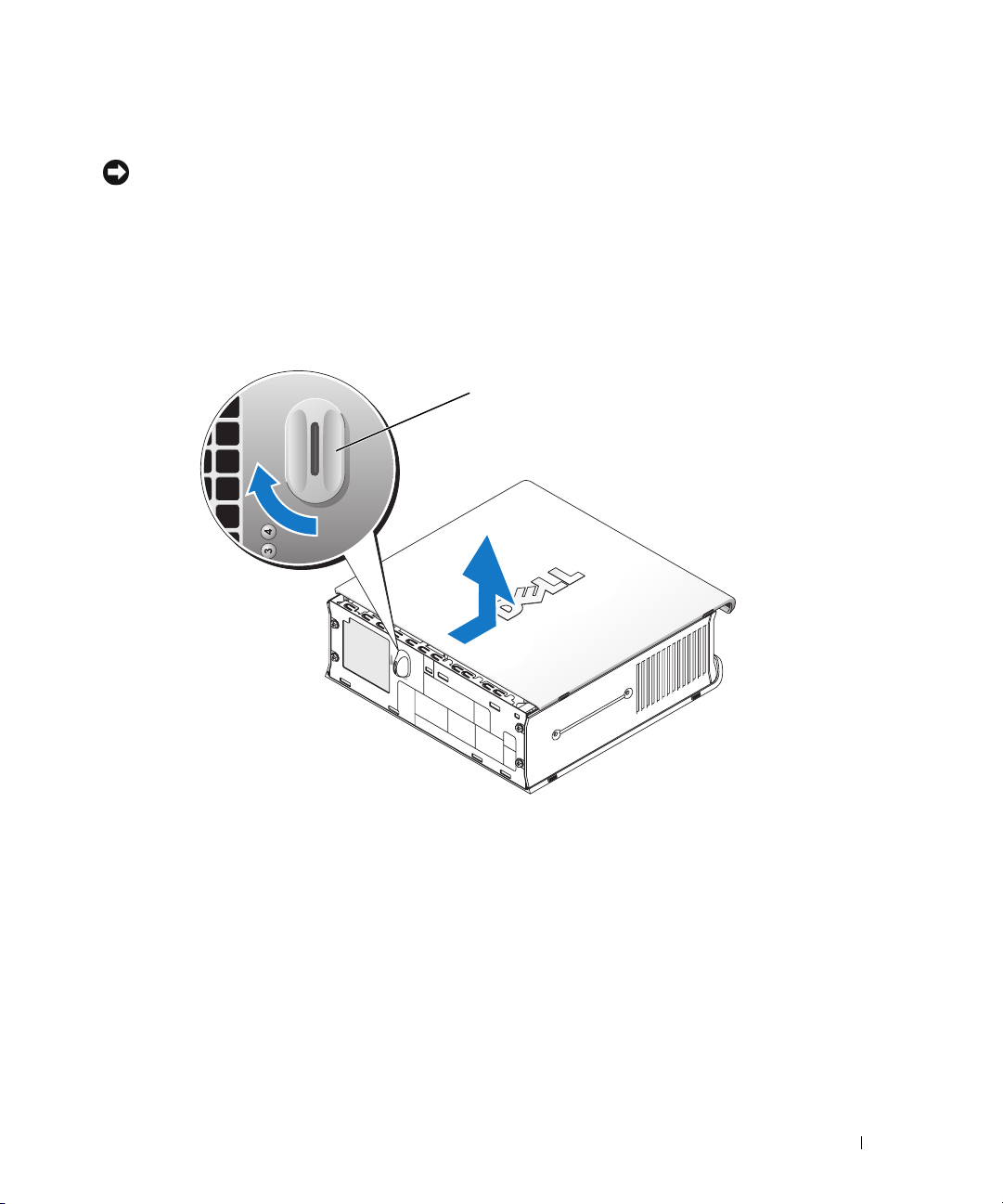
Ultra-Small Form Factor Computer
NOTICE: Before touching anything inside your computer, ground yourself by touching an unpainted
metal surface. While you work, periodically touch an unpainted metal surface to dissipate any static
electricity that could harm internal components.
1
Follow the procedures in "Before You Begin" on page 20
2
Rotate the cover release knob in a clockwise direction.
3
Slide the computer cover forward by approximately 1 cm (½ inch), or until it stops, and then
raise the cover.
1
.
1 cover release knob
Quick Reference Guide 25
Inside Your Computer
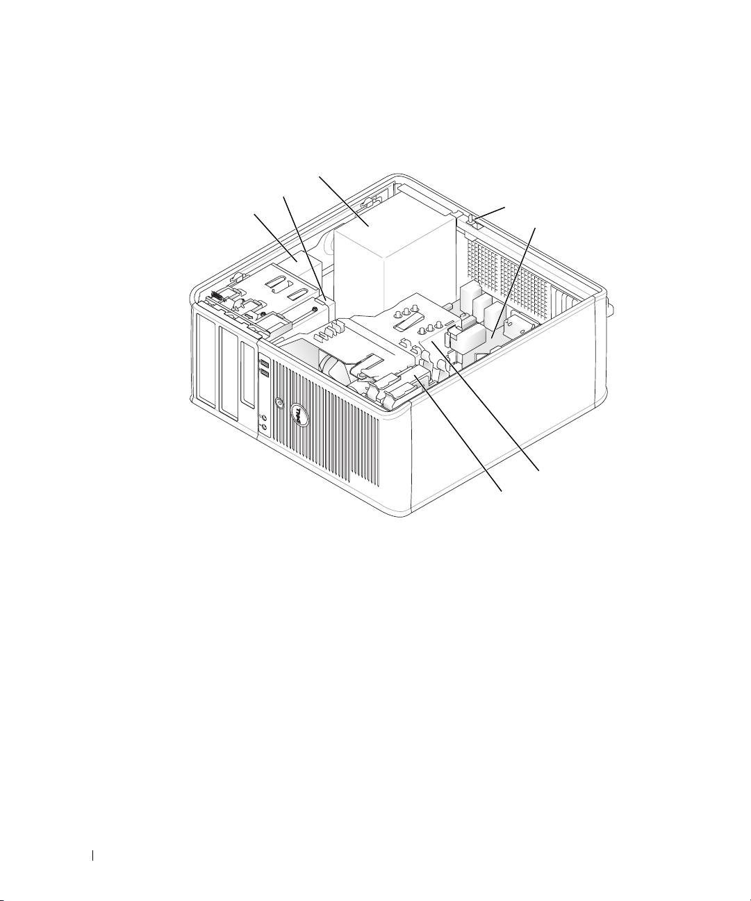
Mini Tower Computer
2
1
3
4
5
6
7
1 CD/DVD drive 5 system board
2 floppy drive 6 heat sink assembly
3 power supply 7 hard drive
4 chassis intrusion switch
26 Quick Reference Guide
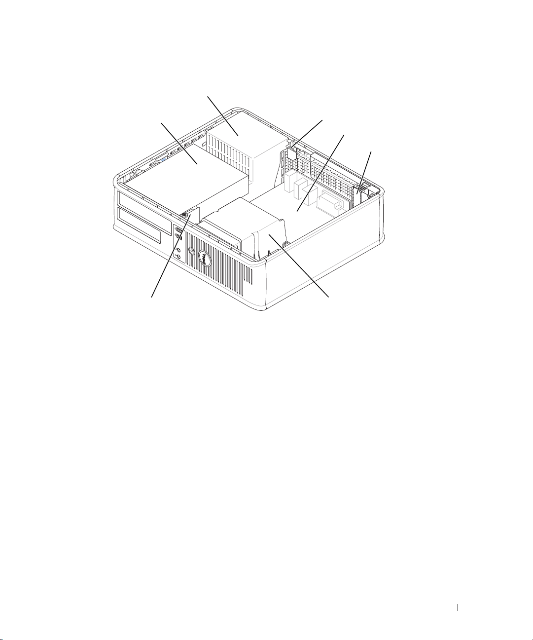
Desktop Computer
2
1
7
1 drives bay (CD/DVD,
floppy, and hard drive)
2 power supply 6 heat sink assembly
3 chassis intrusion switch 7 front I/O panel
4 system board
5 card slots (3) for one PCI Express
x16 card and two PCI cards
3
4
5
6
Quick Reference Guide 27
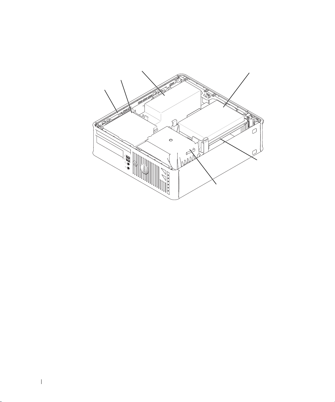
Small Form Factor Computer
3
2
1
6
1 drive release latch 4 hard drive
2 CD/DVD drive 5 system board
3 power supply and fan 6 heat sink assembly
4
5
28 Quick Reference Guide
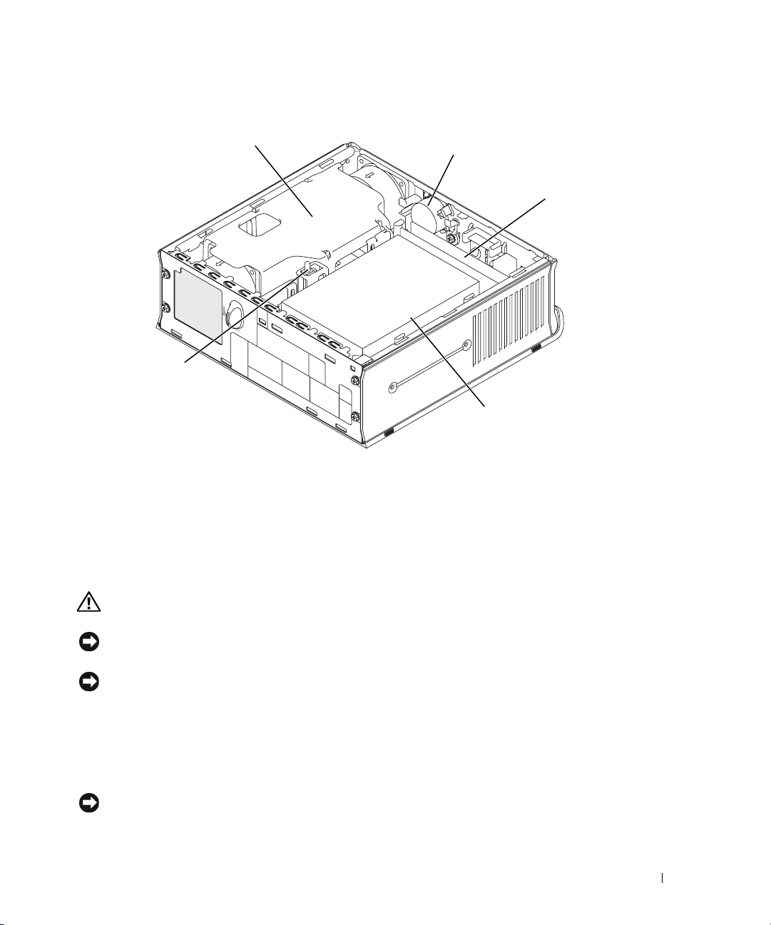
Ultra-Small Form Factor Computer
1
5
1 heat sink assembly 4 hard drive
2 speaker (optional) 5 chassis intrusion switch
3 memory modules (2)
2
4
3
Setting Up Your Computer
CAUTION: Before performing any of the procedures in this section, follow the safety instructions in
Product Information Guide.
NOTICE: If your computer has an expansion card installed (such as a modem card), connect the
appropriate cable to the card, not to the connector on the back panel.
NOTICE: To help allow the computer to maintain proper operating temperature, ensure that you do not
place the computer too close to a wall or other storage compartment that might prevent air circulation
around the chassis.
You must complete all the steps to properly set up your computer. See the appropriate figures
that follow the instructions.
Connect the keyboard and mouse.
1
NOTICE: Do not attempt to operate a PS/2 mouse and a USB mouse simultaneously.
Quick Reference Guide 29
 Loading...