

Page 1
Dell™ OptiPlex™ GX50 Systems
Before You Begin
Computer Cover
Inside the Computer
Chassis Intrusion Switch
Front-Panel Inserts
Control Panel and Badge
I/O Panel
Drives
Expansion-Card Cage (Small Desktop Computer Only)
Expansion Card
Memory
Microprocessor
Power Supply
System Board
Hints, Notices, and Cautions
HINT: A HINT indicates important information that helps you make better use of your computer.
NOTICE: A NOTICE indicates either potential damage to hardware or loss of data and tells you how to avoid the
problem.
CAUTION: A CAUTION indicates a potential for property damage, personal injury, or death.
Information in this document is subject to change without notice.
© 2002 Dell Computer Corporation. All rights reserved.
Reproduction in any manner whatsoever without the written permission of Dell Computer Corporation is strictly forbidden.
Trademarks used in this text: Dell, the DELL logo, and OptiPlex are trademarks of Dell Computer Corporation; Microsoft, MS-DOS, and Windows NT
are registered trademarks of Microsoft Corporation.
Other trademarks and trade names may be used in this document to refer to either the entities claiming the marks and names or their products.
Dell Computer Corporation disclaims any proprietary interest in trademarks and trade names other than its own.
January 2002 Rev A02
Page 2

Back to Contents Page
Before You Begin
Dell™ OptiPlex™ GX50 Systems
Getting Started
Precautionary Measures
Getting Started
This section provides procedures for removing and replacing the components, assemblies, and subassemblies in the Dell™
OptiPlex™ GX50 computers. Unless otherwise noted, each procedure assumes that the following conditions exist:
You have performed the steps in "Precautionary Measures."
You have opened the computer cover.
Recommended Tools
The GX50 computer is primarily a tool-less one, but certain procedures (such as removing drive bracket rails and removing
the control panel) require the use of one or more of the following tools:
Small flat-blade screwdriver
#1 and #2 Phillips-head screwdrivers
An 8-inch, #2 Phillips-head screwdriver
Also, Dell recommends that you use a wrist-grounding strap as explained in "Precautionary Measures
."
Precautionary Measures
Before you perform any procedure in this section, read the following caution for your personal safety and to prevent damage
to the computer from electrostatic discharge (ESD).
CAUTION: FOR YOUR PERSONAL SAFETY AND PROTECTION OF THE EQUIPMENT
Before you start to work on the computer, perform the following steps in the sequence listed:
1. Turn off the computer and all attached devices.
2. Disconnect the computer and devices from their AC power sources. Also, disconnect any telephone or
telecommunication lines from the computer. Doing so reduces the potential for personal injury or shock.
If you are disconnecting a device from the computer or are removing a component from the system board, wait 15 to
30 seconds after disconnecting the computer from AC power before disconnecting the device or removing the
component to avoid possible damage to the system board.
Verify that the auxiliary power light on the system board is not on. If it is on, you may need to wait 15 to 30 seconds
for it to go out (see "System Board Components
3. Wear a wrist-grounding strap, and clip it to an unpainted metal surface, such as the padlock ring on the back of the
computer. If a wrist-grounding strap is not available, touch an unpainted metal surface on the computer, such as the
power supply, to discharge static charge from your body before touching anything inside the computer. While you work,
periodically touch an unpainted metal surface on the computer to dissipate static electricity that might harm internal
components.
" for the location of this light).
Page 3

In addition, take note of the following safety guideline when appropriate:
Handle components and cards with care. Do not touch the components or contacts on a card. Hold a card by it edges
or by its metal mounting bracket. Hold a component such as a microprocessor by its edges, not by its pins.
Back to Contents Page
Page 4
Back to Contents Page
Computer Cover
Dell™ OptiPlex™ GX50 Systems
Opening the Computer Cover
Closing the Computer Cover
Opening the Computer Cover
NOTE: If your computer is on a stand, remove the stand before you open the computer cover.
Small Form-Factor Computer
1 Security cable slot
2 Padlock ring
3 Release buttons (one on each side)
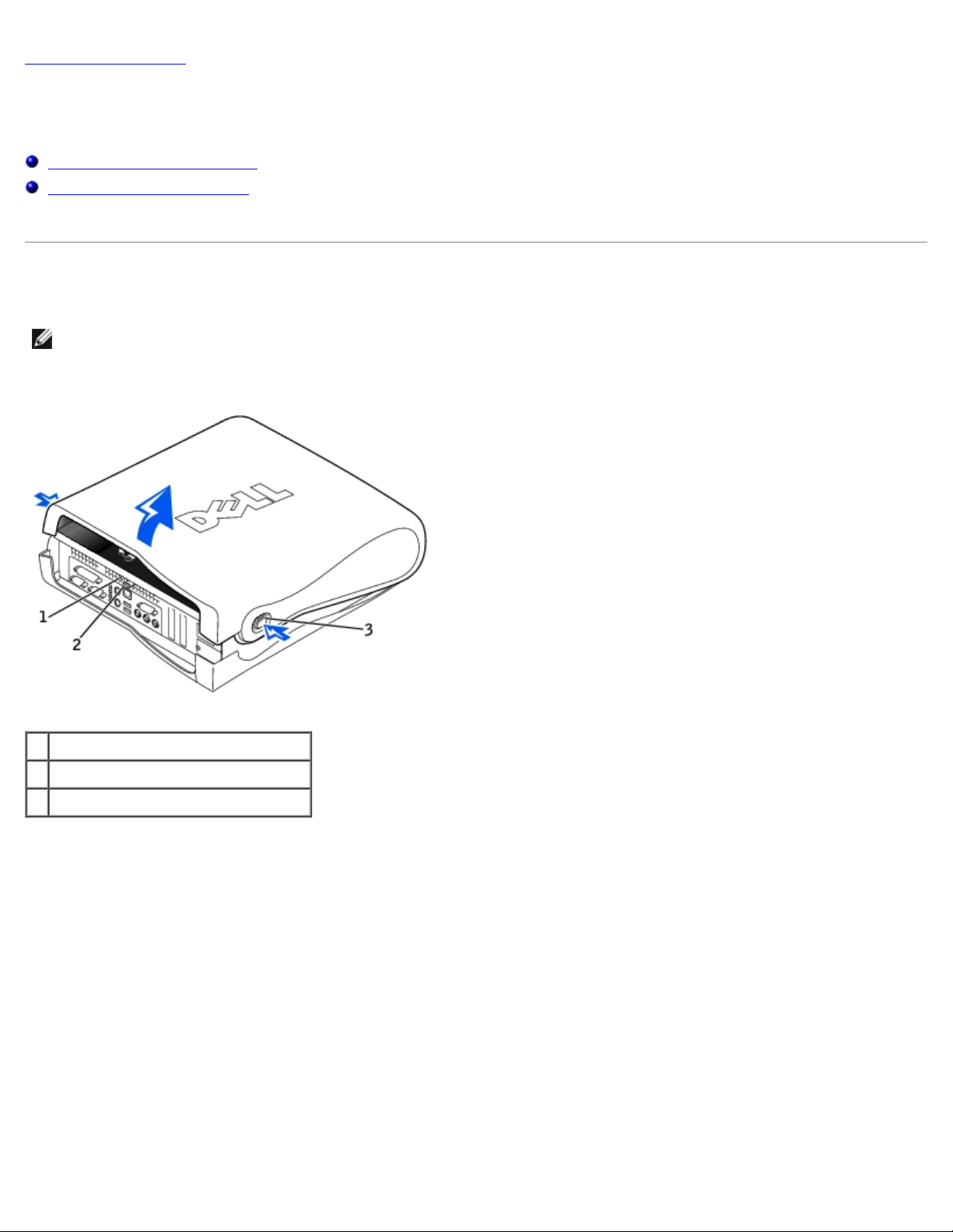
Small Desktop Computer
Page 5

1 Security cable slot
2 Padlock ring
3 Release buttons (one on each side)
Small Mini-Tower Computer
1 Release buttons (one on each side)
2 Padlock ring
3 Security cable slot
1. Remove the padlock from the padlock ring, if present.
Page 6

NOTICE: Do not open the cover if the computer is on the edge of a desk or table. Doing so may cause the computer to
tip over and fall. Make sure that the computer is situated so that there is at least 12 inches of desk- or table-top for
the cover to rest on.
2. Press in on the two securing buttons until the cover is free to swing up.
3. On the small mini-tower computer, press the release button on the right side of the computer with one hand while
pulling up on the top of the cover with the other hand. Then, press the release button on the left side of the computer
with one hand while pulling up on the top of the cover with the other hand. Hold the bottom of the computer with one
hand, and then pull open the cover with the other hand.
Closing the Computer Cover
1. Check all cable connections, especially those that might have come loose during your work. Fold cables out of the way
so that they do not catch on the computer cover. Make sure cables are not routed over the drive cage—they will
prevent the cover from closing properly.
2. Check to see that no tools or extra parts (including screws) are left inside the computer.
3. Close the computer cover by pivoting the cover down toward the back of the computer and into position. Press on the
right side of the cover until it closes securely. Then, press on the left side of the cover until it closes securely.
4. Replace the padlock, if required.
NOTE: After you open and close the cover, the chassis intrusion detector causes the following message to be
displayed at the next computer start-up:
ALERT! Cover was previously removed.
See "Resetting the Chassis Intrusion Detector
Back to Contents Page
" for instructions.
Page 7
Back to Contents Page
Inside the Computer
Dell™ OptiPlex™ GX50 Systems
Key Components
Computer Cables
Key Components
Inside the Small Form-Factor Computer
1 Hard drive 7 System board
2 3.5-inch floppy drive 8 Power supply
3 CD drive 9 AC power connector
4 Cover release buttons (2) 10 I/O ports and connectors
5 Internal speaker 11 Padlock ring
6 Chassis intrusion switch 12 Heat sink assembly
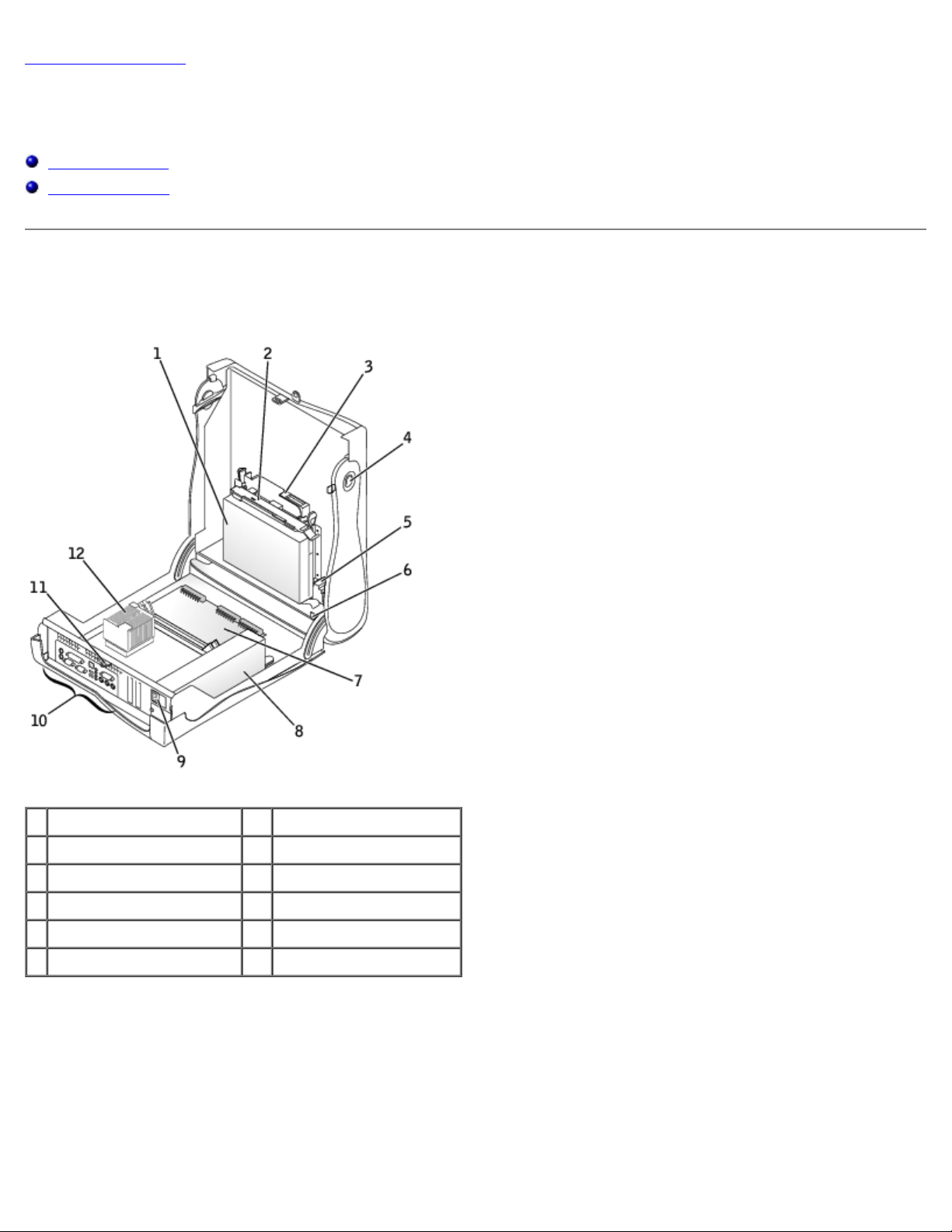
Inside the Small Desktop Computer
Page 8
1 Cover release buttons (2) 8 AC power connector
2 Hard drive 9 Padlock ring
3 Internal speaker 10 I/O ports and connectors
4 Chassis intrusion switch 11 Heat sink assembly
5 Expansion-card cage 12 System board
6 Power supply 13 3.5-inch floppy drive
7 Expansion-card slots 14 CD drive
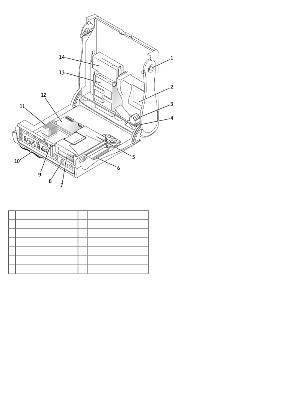
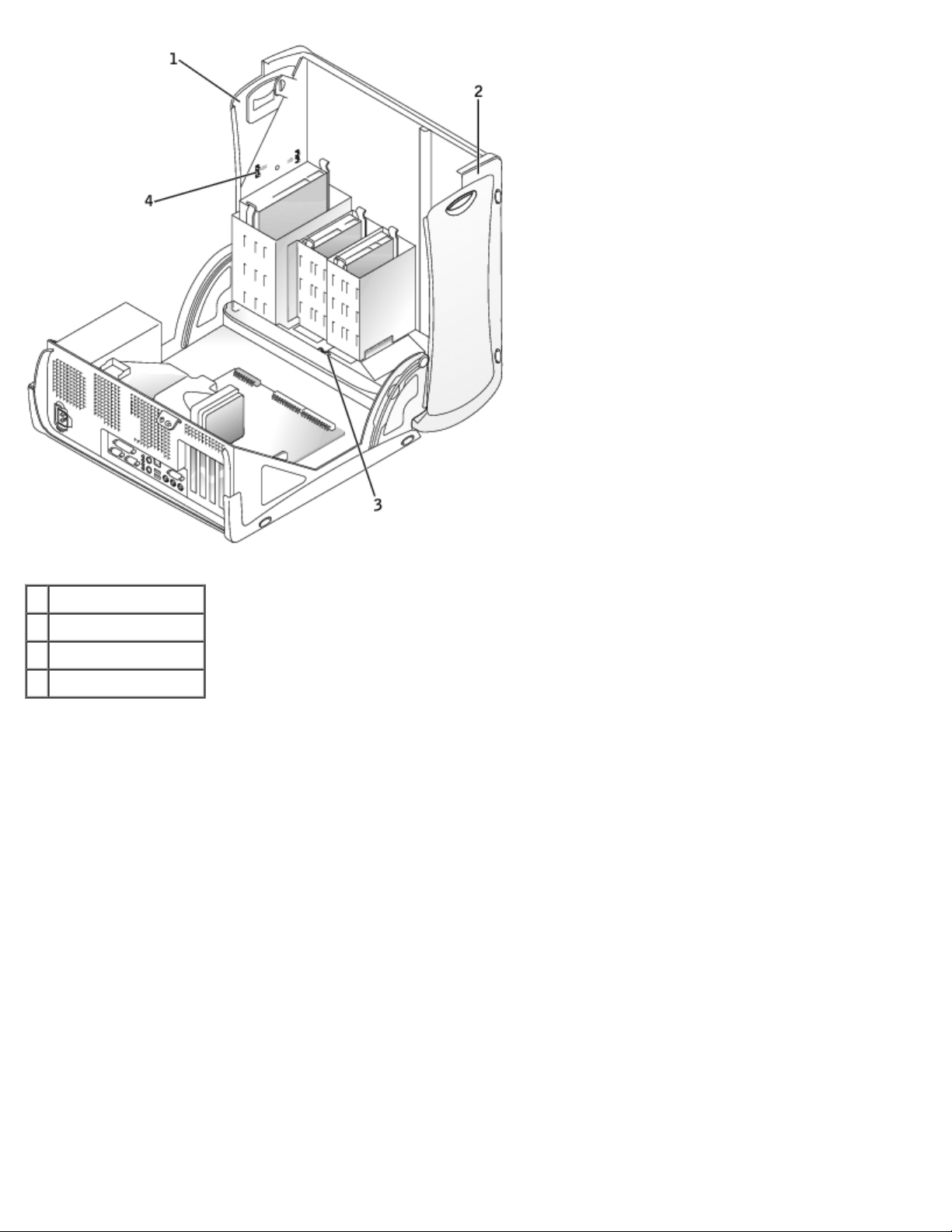
Inside the Small Mini-Tower Computer
Page 9

1 Cover release buttons (2) 8 AC power connector
2 Hard drive 9 Padlock ring
3 Internal speaker 10 Microprocessor and airflow shroud
4 Chassis intrusion switch 11 Power supply
5 System board 12 3.5-inch floppy drive
6 Expansion-card slots 13 CD drive
7 I/O ports and connectors
Computer Cables
Small Form-Factor Computer
Page 10

1 CD drive data cable 6 IDE data cable (hard drive)
2 Floppy drive data cable 7 Input/output cable
3 Control panel cable 8 Input/output audio cable
4 CD drive power cable 9 CD audio cable
5 IDE drive power cable (hard drive)
Small Desktop Computer
Page 11
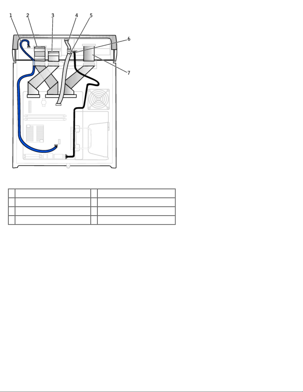
1 CD drive audio cable 5 Front I/O cable
2 CD drive data cable 6 Front I/O audio cable
3 3.5-inch floppy drive data cable 7 EIDE interface cable (hard drive)
4 Control panel cable
Small Mini-Tower Computer
Page 12
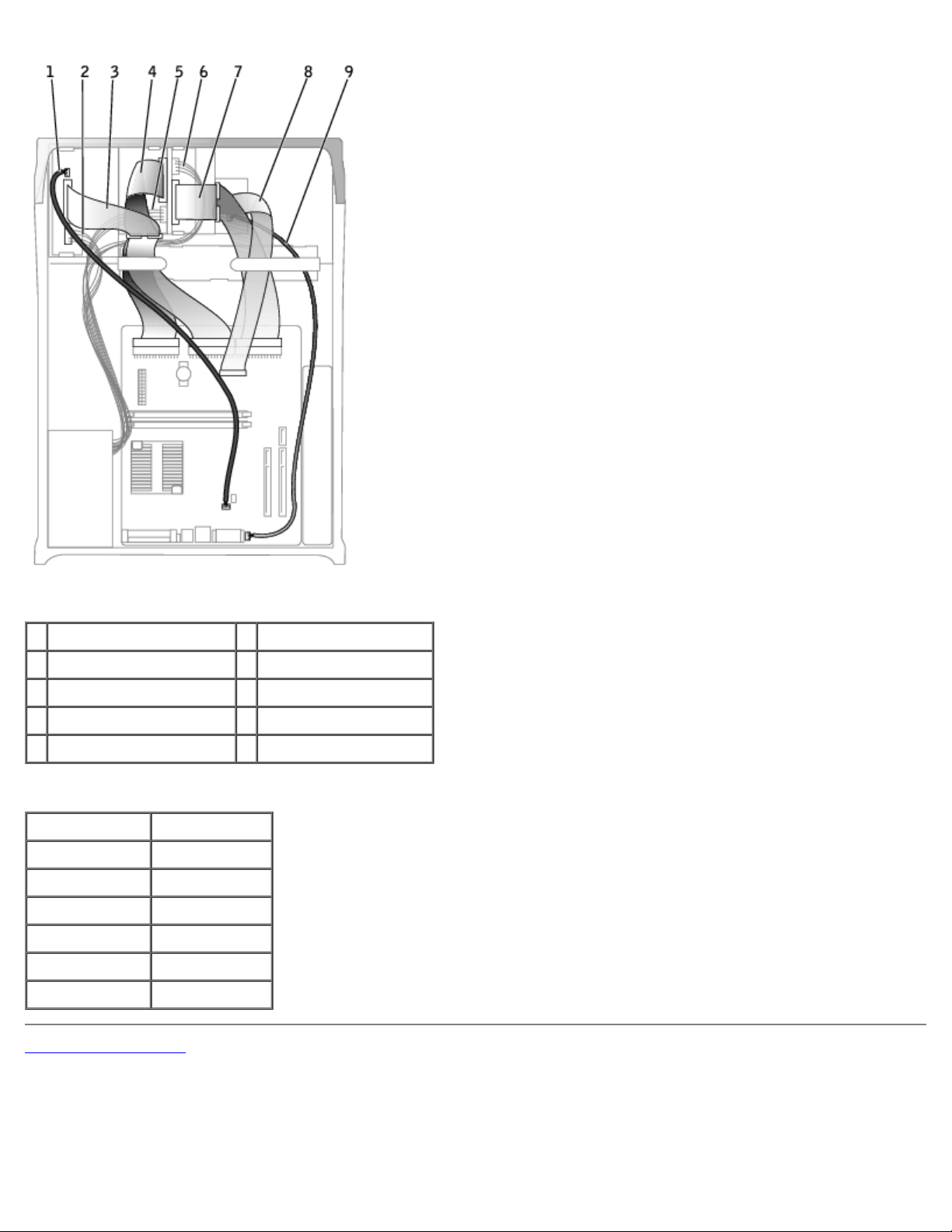
1 CD drive audio cable 6 Hard drive power cable
2 CD drive power cable 7 Hard drive data cable
3 CD drive data cable 8 Front I/O cable
4 Floppy drive data cable 9 Front I/O audio cable
5 Floppy drive power cable
Cable Colors
Hard drive Blue pull tab
Floppy drive Black pull tab
CD drive Orange pull tab
ATA or IDE Gray
Control panel Gray
CD audio Blue
Computer audio Black
Back to Contents Page
Page 13
Back to Contents Page
Chassis Intrusion Switch
Dell™ OptiPlex™ GX50 Systems
Removing the Chassis Intrusion Switch
Replacing the Chassis Intrusion Switch
Resetting the Chassis Intrusion Detector
Removing the Chassis Intrusion Switch
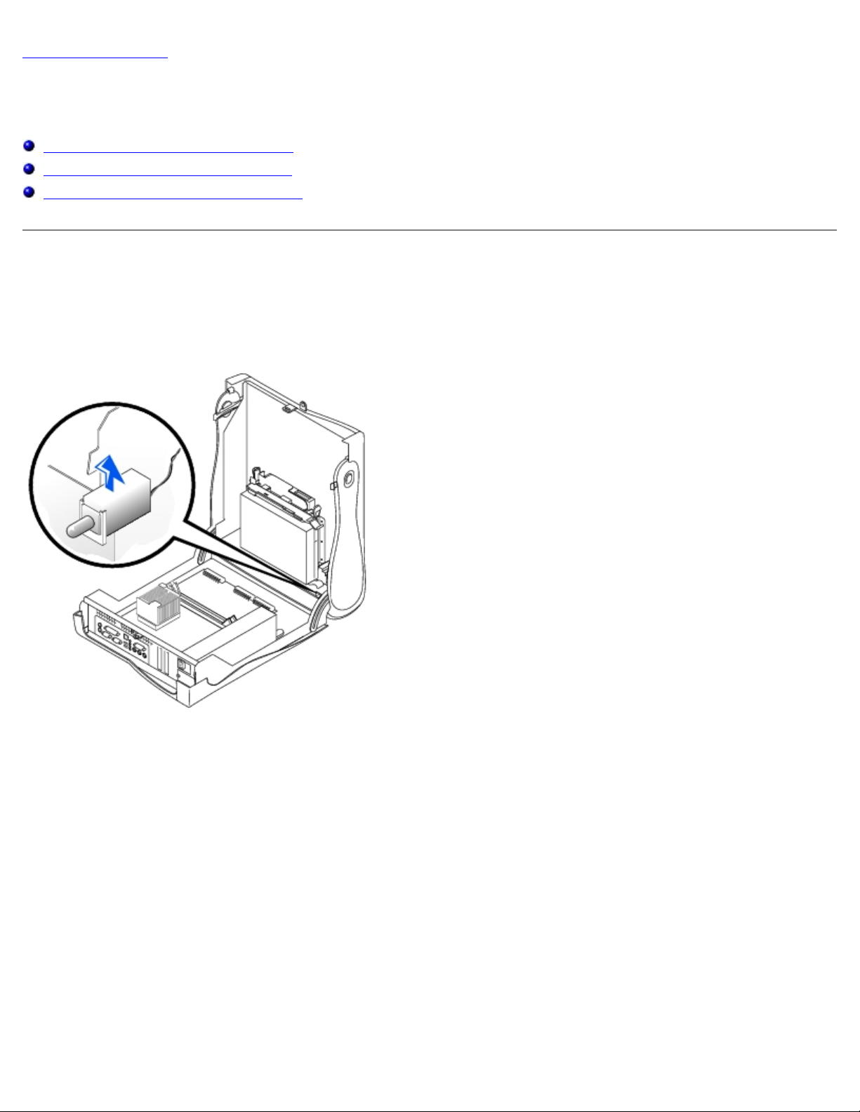
Small Form-Factor Computer
Small Desktop Computer
Page 14
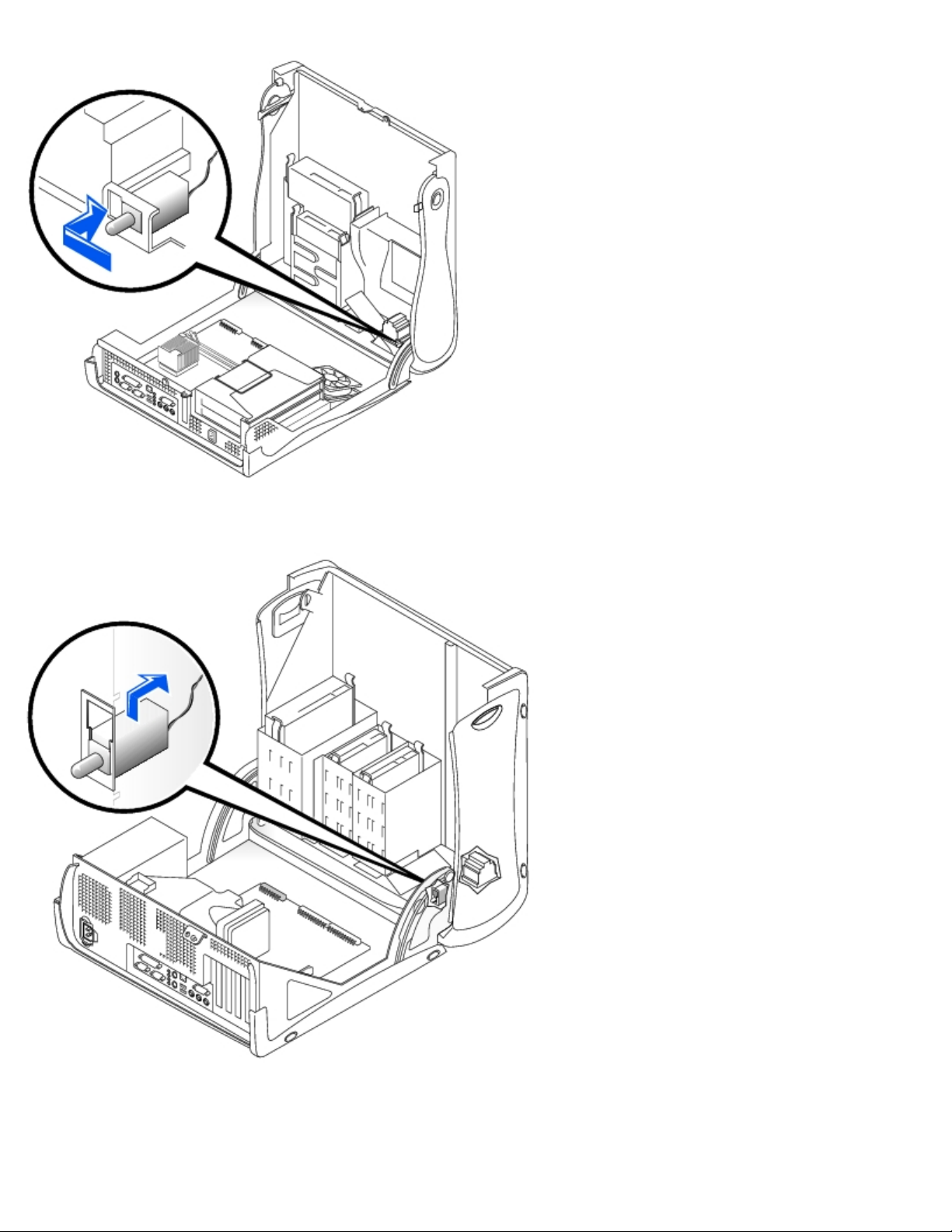
Small Mini-Tower Computer
1. Disconnect the chassis intrusion switch cable connector from the front I/O panel.
Note the routing of the chassis intrusion cable as you remove it from the chassis. Chassis hooks may hold the cable in
place inside the chassis.
Page 15

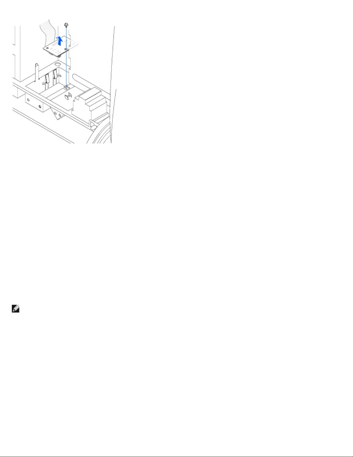
2. Slide the chassis intrusion switch out of its slot and remove the switch and its attached cable from the chassis.
Replacing the Chassis Intrusion Switch
To replace the chassis intrusion switch, follow the "Removing the Chassis Intrusion Switch" procedures in reverse order.
Resetting the Chassis Intrusion Detector
1. Enter system setup by pressing <F2> during the computer's POST.
NOTE: For instructions on using system setup, see the User's Guide.
2. Under the System Security tab, reset the Chassis Intrusion option by pressing the left- or right-arrow key to select
Reset. Change the setting to Enabled, Enabled-Silent, or Disabled.
NOTE: The default is Enabled-Silent.
NOTE: If a setup password has been assigned by someone else, contact the network administrator for
information on resetting the chassis intrusion detector.
3. Press <Alt><B> to restart the computer and implement your changes.
Back to Contents Page
Page 16
Back to Contents Page
Front-Panel Inserts
Dell™ OptiPlex™ GX50 Systems
Removing Front-Panel Inserts
Replacing Front-Panel Inserts
Removing Front-Panel Inserts
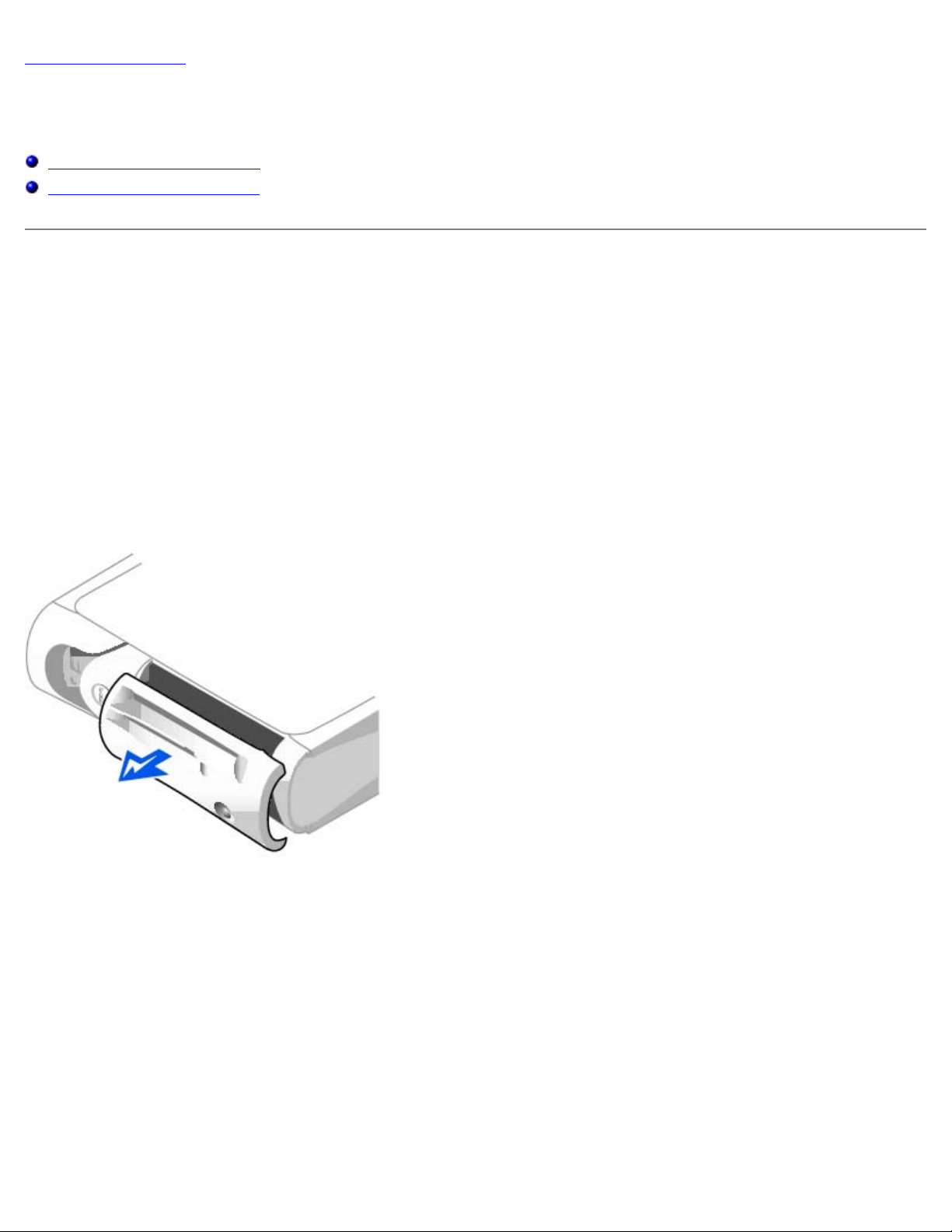
1. On the small form-factor and small desktop computers, perform the following steps:
a. Face the front of the computer and use your fingers to remove the front-panel cover.
b. Press on the insert until it pops free of the front-panel cover.
2. On the small mini-tower computer, perform the following steps:
a. Open the computer cover and release the insert tabs from inside the chassis.
b. Press on the insert until it pops free of the front-panel cover.
Small Form-Factor Computer
Page 17
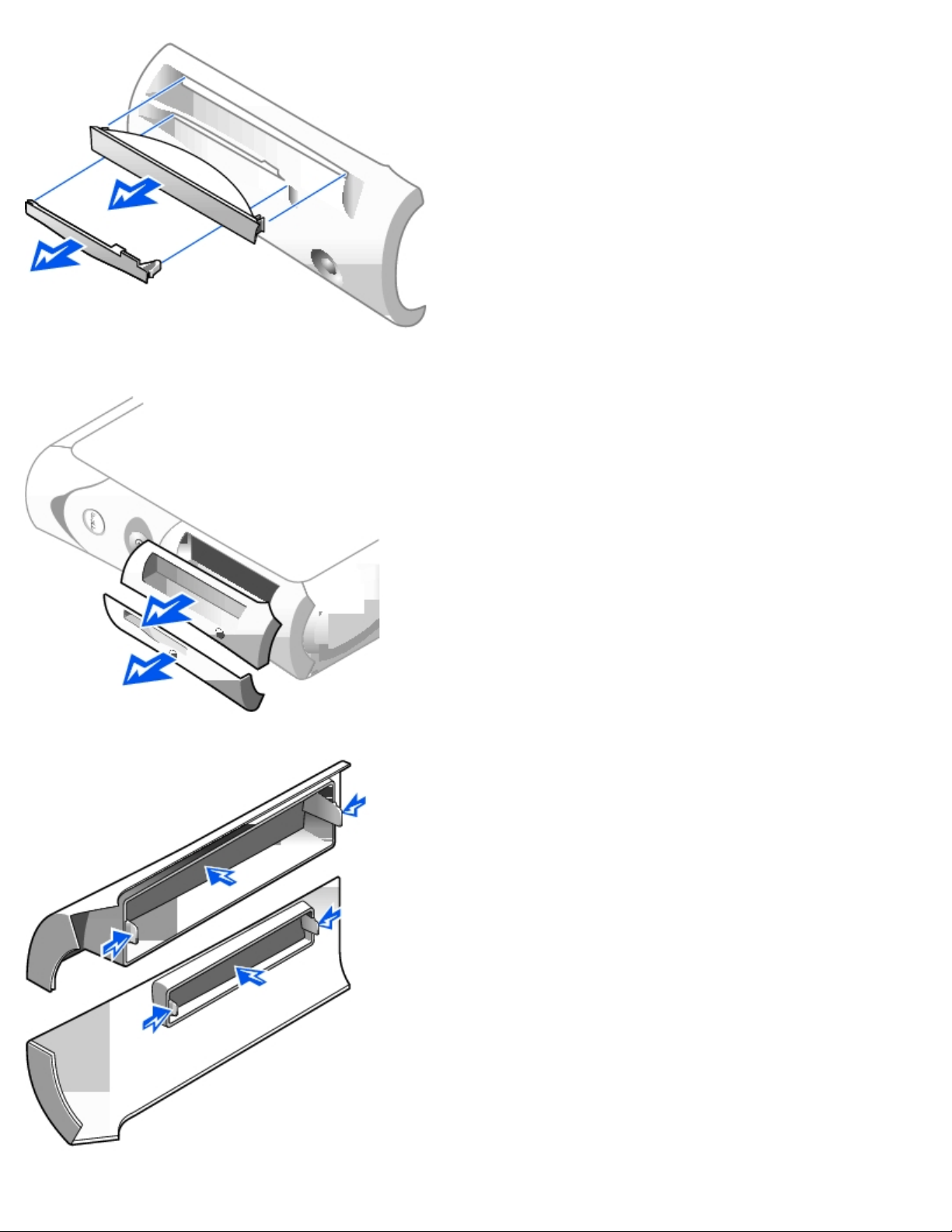
Small Desktop Computer
Page 18

Small Mini-Tower Computer
Replacing Front-Panel Inserts
To replace a front-panel insert, follow the appropriate procedure, in reverse, in "Removing Front-Panel Inserts."
Back to Contents Page
Page 19
Back to Contents Page
Control Panel and Badge
Dell™ OptiPlex™ GX50 Systems
Removing the Control Panel and Badge
Replacing the Control Panel and Badge
Removing the Control Panel and Badge
Small Form-Factor Desktop Computer
1. Open the computer cover.
2. Using a flat-blade screwdriver, release the tabs from the inside of the computer and remove the plastic computer cover
from the metal component.
Releasing the Tabs—Small Form-Factor Computer
1 Tabs (2 on each side)
3. To remove the badge, remove the accent door by pressing the middle of the door while lifting away the sides of the
door.
a. From inside the front bezel, push in on the two tabs on either side of the badge to release the badge.
b. Press on the badge until it is freed.
Page 20
4. To remove the control panel, perform the following steps:
Removing the Control Panel—Small Form-Factor Computer
a. Remove the metal control-panel shield.
b. Remove the screw that holds the control panel to the computer.
Small Desktop Computer
1. To remove the badge, open the front USB door.
a. From inside the door, push in the two tabs on either side of the badge to release the badge.
b. Press on the badge until it is freed.
2. To remove the control panel, perform the following steps:
a. Remove the front I/O panel
Removing the Control Panel—Small Desktop Computer
.
Page 21
b. Using an 8-inch #2 Phillips screwdriver, remove the screw holding the control panel to the computer, and pull
the panel up and away from the computer.
Small Mini-Tower Computer
1. To remove the badge, open the front USB door.
a. From inside the door, push in the two tabs on either side of the badge to release the badge.
b. Press on the badge until it is freed.
2. To remove the control panel, perform the following steps:
a. Lay the computer on its right side and open the cover.
b. Remove the top and bottom panels of the computer by releasing the eight tabs on each panel.
c. Remove the front bezel by releasing the three tabs located on the front bezel: one tab is located by the CD drive,
and two tabs are located by the I/O panel.
NOTE: This view of the small mini-tower chassis shows the CD drive data cable removed.
Front Bezel Tabs—Small Mini-Tower Computer
Page 22
1 Top panel
2 Bottom panel
3 Front-panel tabs (3)
4 Top-panel tabs (8)
d. Close the cover and remove the front bezel.
Control-Panel Removal
Page 23

e. Remove the screw holding the control panel to the chassis, and pull the panel up and away from the chassis.
Replacing the Control Panel and Badge
Small Form-Factor Desktop Computer
1. Replace the control panel and the control-panel shield.
2. Replace the plastic computer cover. Make sure that the two metal hooks and tabs are securely in place.
Replacing the Plastic Computer Cover—Small Form-Factor Computer
Page 24

1 Metal hooks (2)
To help replace the plastic computer cover, remove the accent door and front mask from the plastic computer cover:
a. Remove the front mask by releasing the tabs on the inside of the plastic computer cover.
b. Remove the accent door by pressing the middle of the door while lifting away the sides of the door.
c. After replacing the plastic computer cover, snap the front mask and accent door into place.
Removing the Front Mask and Accent Door—Small Form-Factor Computer
Page 25

1 Accent door
2 Front mask
3. Replace the badge by following, in reverse order, the procedures in "Removing the Control Panel and Badge
small form-factor desktop computer.
" for the
Small Desktop Computer
1. Replace the control panel and secure it to the computer by replacing the screw you removed in step 2 of the removal
procedure.
2. Replace the front I/O panel.
3. Replace the badge by following, in reverse order, the procedures in "Removing the Control Panel and Badge
small desktop computer.
" for the
Small Mini-Tower Computer
1. Replace the control panel by following the "Removing the Control Panel and Badge" procedure in reverse, ensuring that
the tabs on the top panel, bottom panel, and front panel are secure.
2. Replace the badge by following, in reverse order, the procedures in "Removing the Control Panel and Badge" for the
small mini-tower computer.
Back to Contents Page
Page 26

Page 27

Back to Contents Page
I/O Panel
Dell™ OptiPlex™ GX50 Systems
Removing the I/O Panel
Replacing the I/O Panel
Removing the I/O Panel
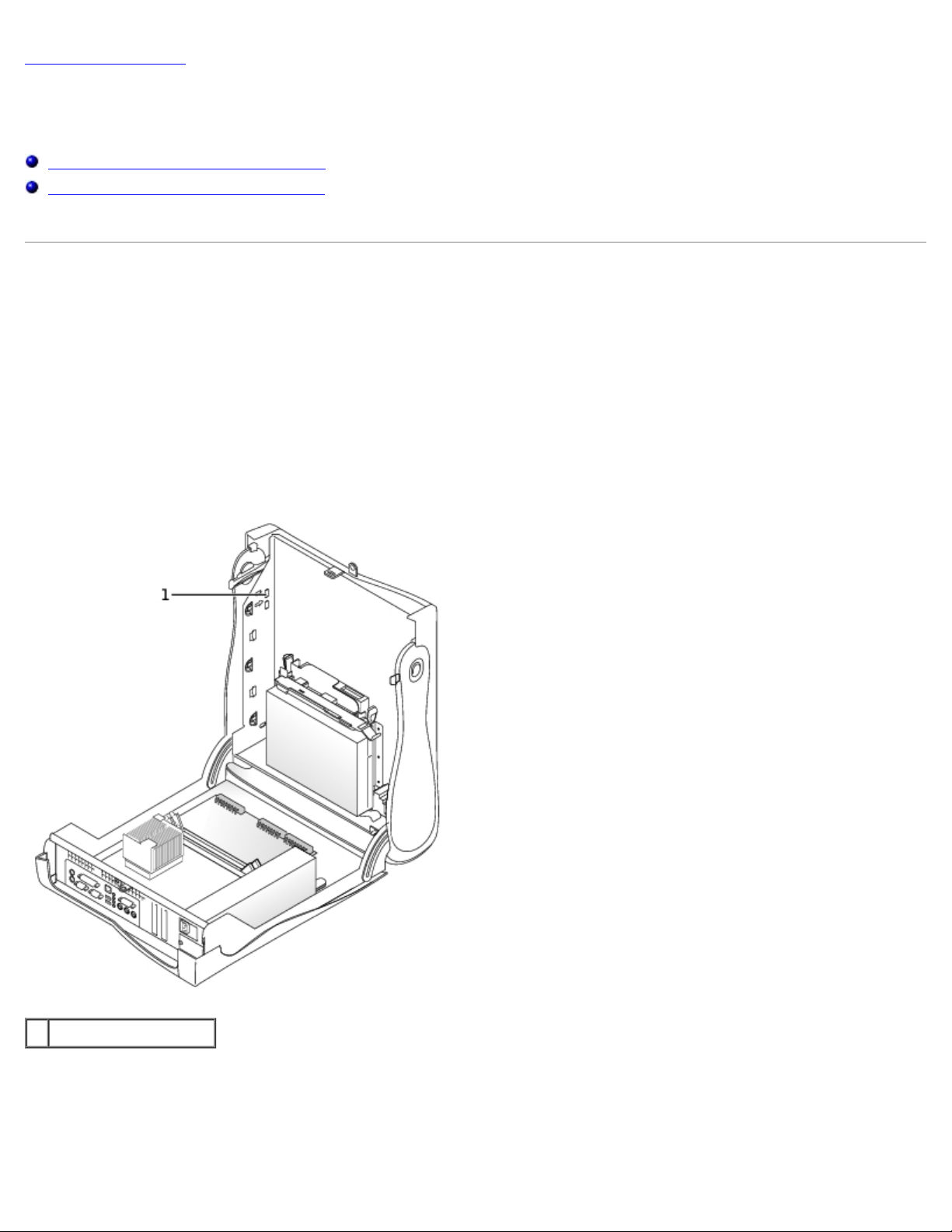
Small Form-Factor Desktop Computer
1. To access the screw that holds the I/O panel to the computer, remove the hard drive.
I/O Panel Removal—Small Form-Factor Computer
1 Internal speaker cable
2 Chassis intrusion switch cable
3 Control-panel cable
4 Front audio cable
5 Mounting screw
6 I/O cable
2. Disconnect the control-panel cable from the control-panel connector on the I/O panel. Disconnect the I/O cable from
the I/O panel.
3. Remove all cables that are connected to the I/O panel, such as the chassis intrusion switch and internal speaker cables.
Page 28

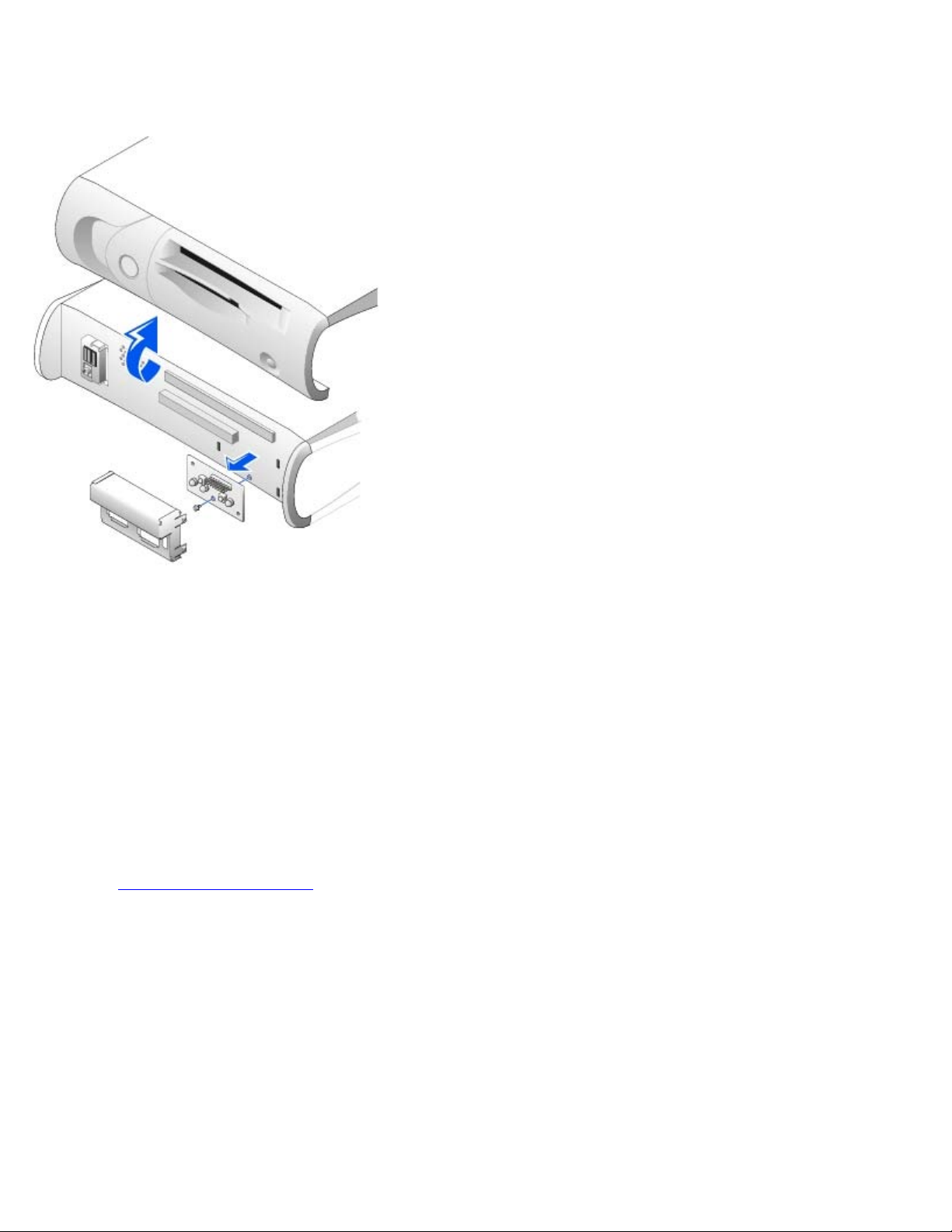
4. From inside the computer cover, remove the mounting screw that secures the I/O panel to the computer.
5. Remove the I/O panel from the computer.
Small Desktop Computer
1. Remove the hard-drive shroud.
2. Disconnect the hard-drive data cable.
3. Disconnect the control-panel cable from the control-panel connector on the I/O panel. Disconnect the I/O cable from
the I/O panel.
Note the routing of the control-panel cable as you remove it from the computer so that you can replace it correctly.
I/O Panel Removal—Small Desktop Computer
1 I/O cable
2 Control-panel cable
3 Front audio cable
4 Mounting screw
5 Chassis intrusion switch cable
6 Internal speaker cable
4. Remove all cables that are connected to the I/O panel, such as the chassis intrusion switch and internal speaker cables.
5. Remove the mounting screw that secures the I/O panel to the computer.
6. Remove the I/O panel from the computer.
Page 29

Small Mini-Tower Computer
I/O Panel Removal—Small Mini-Tower Computer
1 Internal speaker cable
2 Chassis intrusion switch cable
3 Mounting screw
4 Control-panel cable
5 Front audio cable
6 I/O cable
1. Disconnect the control-panel cable from the control-panel connector on the I/O panel. Disconnect the I/O cable from
the I/O panel.
Note the routing of the control-panel cable as you remove it from the computer so that you can replace it correctly.
2. Remove all cables that are connected to the I/O panel, such as the chassis intrusion switch and internal speaker cables.
3. From inside the chassis cover, remove the mounting screw that secures the I/O panel to the chassis.
4. Remove the I/O panel from the chassis.
Replacing the I/O Panel
Page 30

To replace the I/O panel, follow the removal procedures in reverse.
Back to Contents Page
Page 31

Back to Contents Page
Drives
Dell™ OptiPlex™ GX50 Systems
Floppy Drive Removal
Floppy Drive Replacement
CD Drive Removal
CD Drive Replacement
Hard Drive Removal
Hard Drive Replacement
Floppy Drive Removal
Small Form-Factor Desktop Computer
1. Disconnect the floppy-drive cable from the system board.
2. Remove the power cable from the interposer board.
3. Remove or raise the drive by pressing on the green tabs on either side of the drive and lifting the drive up.
4. Remove the floppy-drive cable from the floppy drive.
a. Remove the interposer board from the floppy drive by pressing on the tab and rotating the interposer board.
Removing the Interposer Board—Small Form-Factor Computer
Page 32

1 Floppy-drive cable
2 Tab
3 Interposer board
4 System board floppy-drive connector (DSKT)
b. To release the floppy-drive cable from the connector, slide the lever until it is fully extended, and then lift the
cable away.
Removing the Floppy-Drive Cable
Page 33

1 Floppy-drive cable
2 Lever
5. Remove the floppy drive from its sled by pulling the sled tab out while pushing the drive up and then sliding the drive
out of the sled.
Removing the Floppy Drive—Small Form-Factor Computer
Page 34

1 Sled tab
2 Sled
Small Desktop and Small Mini-Tower Computers
1. Disconnect the cables from the floppy drive and system board.
Small Desktop Computer
Page 35

1 Power cable
2 Floppy-drive cable
3 Floppy-drive system board connector
Small Mini-Tower Computer
1 Power cable
2 Floppy-drive cable
3 Floppy-drive system board connector
Page 36

2. Press inward on the two tabs on the sides of the drive bay to disengage the drive from the computer.
3. Slide the drive upward and remove it from the computer.
Small Desktop Computer
Small Mini-Tower Computer
Floppy Drive Replacement
Small Form-Factor Desktop Computer
1. Snap the replacement drive into the sled and ensure that it is secure in the sled.
2. Connect the interposer board to the floppy drive.
a. Slide the floppy-drive cable into the connector.
b. Close the lever so that the cable is secure in the connector.
Page 37

c. Line up the hole on the bottom of the interposer board with the notch on the connector, and snap the interposer
board onto the drive.
3. Gently slide the drive into the computer until the tabs securely click into position.
Attaching the Floppy-Drive Data Cable
1 Connector notch
2 Interposer board alignment hole
3 Floppy-drive cable
4 Lever
4. Attach the power cable to the interposer board on the floppy drive.
5. Connect the strip cable to the DSKT connector on the system board.
6. Check all cable connections, and fold cables out of the way to provide airflow for the fan and cooling vents.
7. Close the computer cover, reconnect your computer and devices to their electrical outlets, and turn them on.
8. Enter system setup and update the appropriate Diskette Drive A option to reflect the size and capacity of your new
floppy drive.
9. Verify that your computer works correctly by running the Dell Diagnostics.
Small Desktop and Mini-Tower Computers
1. If the replacement drive does not have the bracket rails attached, remove the rails from the old drive by removing the
two screws that secure each rail to the drive. Attach the bracket to the new drive by aligning the screw holes on the
drive with the screw holes on the bracket rails and tightening all four screws (two screws on each rail).
Page 38

Floppy Drive Bracket Rails
1 Drive
2 Bracket rails (2)
3 Screws (4)
2. Gently slide the drive into place until the tabs securely click into position.
3. Attach the power and data cables to the floppy drive, and connect the other end of the data cable to the connector
labeled "DSKT" on the system board.
Small Desktop Computer
1 Power cable
2 Floppy-drive cable
3 Floppy-drive system board connector
Page 39

Small Mini-Tower Computer
1 Power cable
2 Floppy-drive cable
3 Floppy-drive system board connector
4. Check all cable connections, and fold cables out of the way to provide airflow for the fan and cooling vents.
5. Close the computer cover, reconnect your computer and devices to their electrical outlets, and turn them on.
6. Enter system setup and update the appropriate Diskette Drive A option to reflect the size and capacity of your new
floppy drive.
7. Verify that your computer works correctly by running the Dell Diagnostics.
CD Drive Removal
Small Form-Factor Desktop Computer
1. Remove the interposer board from the CD drive.
Removing the Interposer Board—Small Form-Factor Computer
Page 40

1 Interposer board
2. Press inward on the two tabs on the sides of the drive to disengage the drive from the computer.
Removing the CD Drive—Small Form-Factor Computer
Small Desktop and Small Mini-Tower Computers
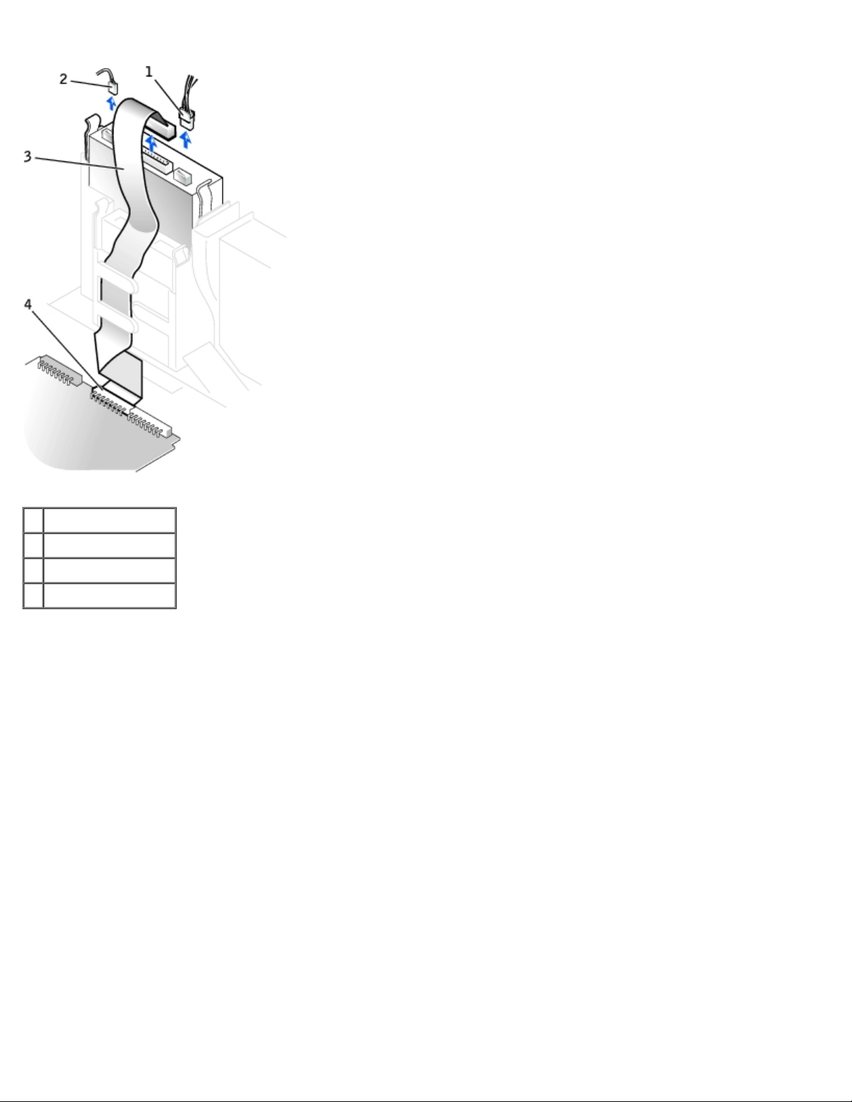
1. Remove the data, power, and audio cables from the drive.
Page 41
Removing Cables—Small Desktop Computer
1 Power cable
2 Audio cable
3 CD drive cable
4 CD drive connector
Removing Cables—Small Mini-Tower Computer
Page 42

1 Power cable
2 Audio cable
3 CD drive cable
4 CD drive connector
2. Press inward on the two tabs on the sides of the drive bay to disengage the drive from the computer.
3. Slide the drive upward and remove it from the computer.
Removing the CD Drive—Small Desktop Computer
Page 43
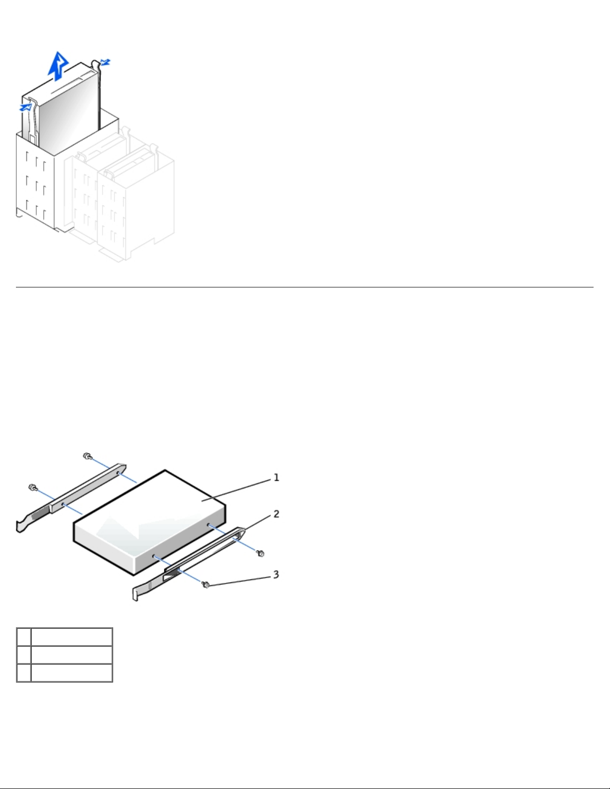
Removing the CD Drive—Small Mini-Tower Computer
CD Drive Replacement
1. If you are replacing a drive that does not have the bracket rails attached, remove the rails from the old drive by
removing the two screws that secure each rail to the drive. Attach the bracket to the new drive by aligning the screw
holes on the drive with the screw holes on the bracket rails and tightening all four screws (two screws for each rail).
2. If you are installing a new drive, connect it to the set of rails that are attached to the inside of the cover.
If a set of rails is not attached to the inside of the cover, contact Dell.
CD Drive Bracket Rails
1 Drive
2 Bracket rails (2)
3 Screws (4)
Small Form-Factor Desktop Computer
1. Gently slide the drive into place until the tabs securely click into position.
Page 44

2. Connect the interposer board to the CD drive, ensuring that the data, power, and audio cables are attached to the
interposer board.
Connecting the Interposer Board—Small Form-Factor Computer
1 Interposer board
Small Desktop and Small Mini-Tower Computers
1. Gently slide the drive into place until the tabs securely click into position.
2. If you are installing a drive that has its own controller card, install the controller card in an expansion slot.
3. Connect the drive, power, and audio cables to the drive.
Connecting Cables—Small Desktop Computer
Page 45
1 Power cable
2 Audio cable
3 CD drive cable
4 CD drive connector
Small Mini-Tower Computer
Page 46

1 Power cable
2 Audio cable
3 CD drive cable
4 CD drive connector
If your computer came with an IDE CD drive, use the spare connector on the existing interface cable. Otherwise, use
the IDE interface cable provided in the drive kit.
4. If you are installing a drive that has its own controller card, install the controller card in an expansion slot.
Hard Drive Removal
Small Form-Factor Desktop Computer
1. Disconnect the power and hard-drive data cables from the drive.
Removing Cables—Small Form-Factor Computer
1 Power cable
2 Hard-drive cable
2. Press in on the tabs on each side of the drive and slide the drive toward the I/O panel and remove it from the
computer.
Removing the Hard Drive—Small Form-Factor Computer
Page 47

3. If the replacement drive does not have the bracket rails attached, remove the rails from the old drive by removing the
two screws that secure each rail to the drive.
Drive Brackets Rails
Small Desktop Computer
1. Remove the plastic shroud covering the hard drive by pressing in on the indented tab at the top of the shroud and
lifting the shroud away.
Removing the Shroud—Small Desktop Computer
Page 48

2. Disconnect the power and hard-drive data cables from the drive.
Removing Cables—Small Desktop Computer
1 Hard-drive cable
2 Power cable
3. Press in on the tabs on each side of the drive and slide it up and out.
Removing the Hard Drive—Small Desktop Computer
Page 49

1 Tabs (2)
2 Hard drive
4. If the replacement drive does not have the bracket rails attached, remove the rails from the old drive by removing the
two screws that secure each rail to the drive.
Drive Brackets Rails
Small Mini-Tower Computer
1. Disconnect the power and hard-drive data cables from the drive.
Removing Cables—Small Mini-Tower Computer
Page 50

1 Power cable
2 Hard-drive cable
2. Press in on the tabs on each side of the drive and slide it up and out.
Removing the Hard Drive—Small Mini-Tower Computer
1 Tabs (2)
2 Hard drive
3. If the replacement drive does not have the bracket rails attached, remove the rails from the old drive by removing the
two screws that secure each rail to the drive.
Drive Brackets Rails
Page 51

Hard Drive Replacement
NOTICE: To avoid possibly damaging the drive by ESD, ground yourself by touching an unpainted metal surface on the
back of the computer.
NOTICE: When you unpack the drive, do not set it on a hard surface, which may damage the drive. Instead, set the
drive on a surface, such as a foam pad, that will sufficiently cushion it.
1. If the replacement drive does not have the bracket rails attached, remove the rails from the old drive by removing the
two screws that secure each rail to the drive.
2. Reinstall the hard drive in the computer by gently sliding the drive into place until you hear it securely click.
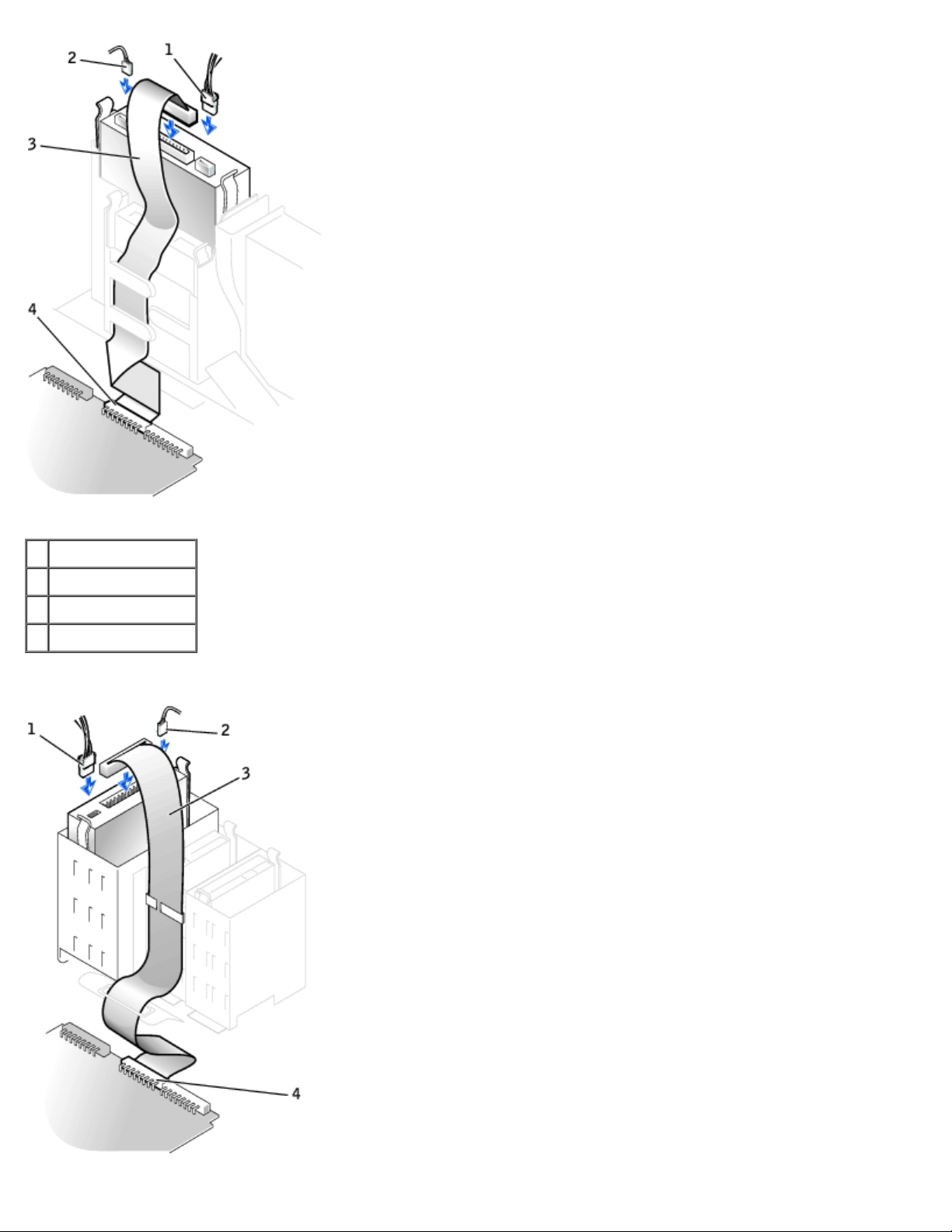
3. Connect the power and hard-drive data cables to the drive.
4. On the small desktop computer, replace the hard-drive shroud by inserting the two tabs on the bottom into the holes in
the computer and snapping the top into place.
Connecting Cables—Small Form-Factor Computer
Page 52

1 Power cable
2 IDE cable
3 IDE1 connector
Connecting Cables—Small Desktop Computer
1 Power cable
2 IDE cable
3 IDE1 connector
Page 53

Connecting Cables—Small Mini-Tower Computer
1 Power cable
2 IDE cable
3 IDE1 connector
5. Check all connectors to be certain that they are properly cabled and firmly seated.
NOTICE: To avoid possible damage to the computer, you must match the colored stripe on the hard-drive data cable
with pin 1 on the hard-drive (IDE1) connector and with the system board interface connector (IDE1).
To locate the system board interface connector (IDE1), see "System Board Components
6. If the drive you just installed is the primary drive, insert a bootable floppy disk into the floppy drive.
7. Turn on the computer.
8. Enter system setup and update the appropriate Primary Drive option, 0 or 1.
See the User's Guide for complete information on system setup.
9. Reset the chassis intrusion detector
10. Restart the computer.
11. Partition and logically format the computer's hard drive before proceeding to the next step.
.
."
For partition and format instructions, refer to the documentation that came with the operating system.
NOTE: On Windows NT computers with hard drives larger than 2 GB, create a primary partition of 2 GB and divide the
remaining capacity into partitions of 2 GB or less. For example, a computer with a 2.5-GB hard drive would have a
primary partition of 2 GB (drive C) and a second partition of 500 MB (drive D).
12. Test the hard drive by running the Dell Diagnostics.
Page 54

See "Solving Problems" in the User's Guide for complete information.
13. If the drive you just installed is the primary drive, install the operating system on the hard drive.
For instructions, refer to the documentation that came with the operating system.
Back to Contents Page
Page 55

Back to Contents Page
Expansion-Card Cage (Small Desktop Computer Only)
Dell™ OptiPlex™ GX50 Systems
Removing the Expansion-Card Cage
Replacing the Expansion-Card Cage
Removing the PCI Riser Board
Replacing the PCI Riser Board
Removing the Expansion-Card Cage
CAUTION: Use a wrist-grounding strap as explained in "Precautionary Measures."
1. Examine any cables connected to expansion cards through the back- panel openings, and disconnect any cables that
will not extend to where the cage must be placed when it is removed from the computer.
2. Remove any cables connected to the expansion card.
3. Gently pull on the handle and lift the expansion-card cage up and away from the computer.
Removing the Expansion-Card Cage
Replacing the Expansion-Card Cage
1. Align the expansion-card cage slots with the tabs in the computer opening for the expansion-card cage. Slide the
expansion-card cage into place.
2. Make sure that the riser board is fully seated in the RISER connector on the system board.
Replacing the Expansion-Card Cage
Page 56

3. Reconnect any cables you removed in steps 1 and 2 of the previous procedure.
Removing the PCI Riser Board
NOTICE: To avoid damage to the expansion cards or the system board by ESD, ground yourself by touching an
unpainted metal surface on the back of the computer.
CAUTION: Use a wrist grounding strap as explained in "Precautionary Measures."
1. Remove the expansion-card cage
2. Remove the expansion cards installed in the slots.
3. Remove the two screws that attach the riser board to the expansion- card cage.
.
Replacing the PCI Riser Board
Follow the "Removing the PCI Riser Board" procedures in reverse order.
Back to Contents Page
Page 57

Back to Contents Page
Expansion Card
Dell™ OptiPlex™ GX50 Systems
Removing an Expansion Card
Replacing an Expansion Card
Your computer provides expansion slots for the following cards:
In the small form-factor computer, one low-profile, 32-bit, 33-MHz PCI card.
In the small desktop computer, up to two 32-bit, 33-MHz PCI cards.
In the small mini-tower computer, up to four 32-bit, 33-MHz PCI cards.
NOTE: Before disconnecting a device from the computer or removing a component from the system board, verify that
the auxiliary power light on the system board is off. For the location of this light, see "System Board Components
Removing an Expansion Card
."
CAUTION: Use a wrist-grounding strap as explained in "Precautionary Measures."
1. If necessary, disconnect any cables connected to the card.
2. On the small desktop computer, remove the expansion-card cage.
3. Press the hinged lever on the expansion card retention arm and raise the retention arm.
4. Grasp the card by its outside corners and ease it out of its connector on the riser board.
5. If you are removing the card permanently, install a metal filler bracket over the empty card-slot opening.
Small Form-Factor Computer
Page 58

1 Card-edge connector
2 Expansion card
3 Hinged lever
4 Retention arm
5 Expansion-card connector
Small Desktop Computer
Page 59

1 Retention arm 5 Expansion-card connector
2 Lever 6 Riser board
3 Expansion card 7 Expansion-card cage
4 Card-edge connector
Small Mini-Tower Computer
1 Expansion card
2 Card-edge connector
3 Expansion-card connector
4 Retention arm
Page 60

5 Lever
Replacing an Expansion Card
CAUTION: Use a wrist-grounding strap as explained in "Precautionary Measures."
CAUTION: Some network cards automatically start the computer when they are connected. To guard
against electrical shock, be sure to unplug the computer from its electrical outlet before installing any
expansion cards.
1. Prepare the expansion card for installation.
See the documentation that came with the expansion card for information on configuring the card, making internal
connections, or otherwise customizing it for your computer.
2. Raise the lever that covers the card-slot opening on the back of the computer.
3. If there is a filler bracket, remove the filler bracket by raising the hinged lever and sliding the bracket up.
Replacing an Expansion Card—Small Form-Factor Computer
1 Expansion-card connector
2 Card-edge connector
3 Expansion card
Replacing an Expansion Card—Small Desktop Computer
Page 61
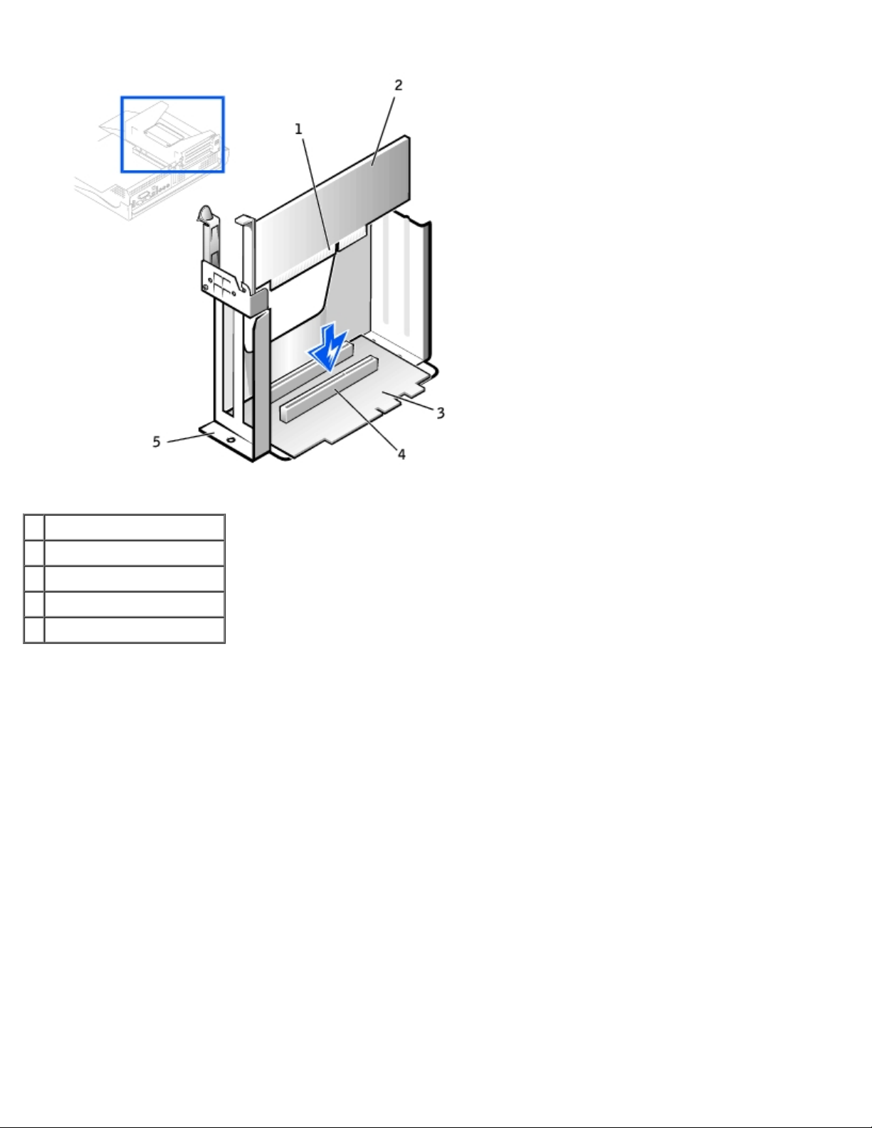
1 Card-edge connector
2 Expansion card
3 Riser board
4 Expansion-card connector
5 Expansion-card cage
4. Place the expansion card on the connector and press down firmly. Make sure that the card is fully seated in the slot.
If the expansion card is full-length, insert the end of the card into the expansion-card guide bracket as you lower the
card toward its connector on the system board. Insert the card firmly into the expansion-card connector on the system
board.
Expansion Card Connection
Page 62

1 Bracket within slot
2 Bracket caught outside of slot
3 Fully seated card
4 Not fully seated card
Replacing an Expansion Card—Small Mini-Tower Computer
1 Filler bracket
2 Alignment bar
3 Alignment guide
4 Retention arm
Page 63

5. Before lowering the retention arm, make sure of the following:
Tops of all expansion cards and filler brackets are flush with the alignment bar.
Notch in the top of the card or filler bracket fits around the alignment guide.
Press the arm into place, securing the expansion card(s) in the computer.
6. Connect any cables that should be attached to the card.
7. In the small desktop computer, replace the expansion-card cage
8. Reconnect the computer and devices to their electrical outlets and turn them on.
9. After you open and close the cover, the chassis intrusion detector causes the following message to be displayed at the
next computer start-up:
ALERT! Cover was previously removed.
See "Resetting the Chassis Intrusion Detector
Back to Contents Page
" for instructions.
.
Page 64

Back to Contents Page
Memory
Dell™ OptiPlex™ GX50 Systems
Removing a Memory Module
Replacing a Memory Module
Removing a Memory Module
CAUTION: Use a wrist-grounding strap as explained in "Precautionary Measures."
1. Press the securing clips outward simultaneously until the memory module disengages and pops out slightly from the
socket.
Removing the Memory Module
2. Lift the module away from the socket.
Replacing a Memory Module
NOTICE: To avoid damage to the memory module, press the module straight down into the socket with equal force
applied at each end of the module.
1. Insert the module straight down into the connector, ensuring that it fits into the vertical guides at each end of the
connector. Press firmly on the ends of the module until it snaps into place.
Replacing a Memory Module
Page 65

Back to Contents Page
Page 66

Back to Contents Page
Microprocessor
Dell™ OptiPlex™ GX50 Systems
Removing the Microprocessor and Cooling Fan/Heat-Sink Assembly
Replacing the Microprocessor and Cooling Fan/Heat-Sink Assembly
Removing the Microprocessor and Cooling Fan/Heat-Sink
Assembly
CAUTION: Use a wrist-grounding strap as explained in "Precautionary Measures."
CAUTION: The microprocessor and heat-sink assembly can get extremely hot. To avoid burns, be sure both
have had sufficient time to cool before you touch them.
1. Disconnect the cooling fan power cable from the FAN connector on the system board.
2. On the small mini-tower computer, remove the airflow shroud as shown in the following illustration.
Airflow Shroud Removal—Small Mini-Tower Computer
1 Anchor tabs
3. Remove the cooling fan/heat-sink assembly.
Page 67

a. Remove the memory module closest to the heat-sink assembly.
b. Pull down on the toggle clip lever until you can unhook the ends of the clip from the tabs on each side of the ZIF
socket.
c. Remove the clip from the socket, and then lift the heat sink from the microprocessor.
Removing the Securing Clip
1 ZIF socket tab
2 Toggle lever
4. Remove the microprocessor chip from the socket.
Removing the Microprocessor Chip
Page 68

1 Microprocessor chip
2 Release lever
3 Microprocessor socket
NOTICE: Be careful not to bend any of the pins when you remove the microprocessor from the ZIF socket. Bending
the pins can permanently damage the microprocessor.
The ZIF socket has a lever-type handle that secures and releases the microprocessor from the ZIF socket.
5. Pull the socket release lever straight up until the microprocessor releases.
6. Remove the microprocessor from the socket.
7. Leave the release lever extended so that the socket is ready for the new microprocessor.
Replacing the Microprocessor and Cooling Fan/Heat-Sink
Assembly
CAUTION: Use a wrist-grounding strap as explained in "Precautionary Measures."
NOTICE: Be careful not to bend any of the pins when you unpack the microprocessor. Bending the pins can
permanently damage the microprocessor.
NOTICE: You must position the microprocessor correctly in the ZIF socket to avoid permanent damage to the
microprocessor and the computer when you turn on the system.
1. Install the microprocessor in the ZIF socket.
If the release lever on the ZIF socket is not all the way out, move it to that position now.
2. Align pin-1 (the corner marked with a triangle) of the microprocessor and pin-1 of the ZIF socket.
Installing the Microprocessor Chip
Page 69

1 Pin-1 corners of chip and socket aligned
3. Set the microprocessor lightly in the socket, making sure that all pins are aligned with the correct holes.
Because the system uses a ZIF socket, there is no need to use force (which could bend the pins if the microprocessor is
misaligned).
4. When the microprocessor is positioned correctly, press it with minimal pressure to fully seat it in the ZIF socket.
5. When the microprocessor is fully seated, pivot the release lever back toward the system board until it snaps into place,
securing the microprocessor.
NOTICE: Ground yourself by touching an unpainted metal surface on the back of the computer.
6. Replace the fan/heat-sink assembly.
NOTICE: On the new heat sink, remove the plastic tab covering the thermal grease before placing the assembly on the
microprocessor.
a. Place the heat-sink assembly on top of the microprocessor.
b. Orient the metal retaining clip as shown in "Removing the Securing Clip
over the tab on the top edge of the ZIF socket.
c. Rotate the lever upward until it snaps into place.
d. Replace the memory module that you removed in step 3
NOTE: If you are installing a microprocessor replacement kit from Dell, return the original heat- sink assembly and
microprocessor to Dell in the same package in which your replacement kit was sent. Your microprocessor replacement
kit should include a replacement microprocessor heat sink. You need to reuse the original securing clip.
7. Reconnect the cooling fan power cable to the FAN connector on the system board.
8. As the system boots, it detects the presence of the new microprocessor and automatically changes the system
configuration information in system setup.
9. After you open and close the cover, the chassis intrusion detector causes the following message to be displayed at the
next system start- up:
of the previous procedure.
," and hook the unhinged end of the clip
Page 70

ALERT! Cover was previously removed.
10. Enter system setup and confirm that the system data area correctly identifies the type of installed microprocessor.
For instructions on using system setup, see the User's Guide.
11. While in system setup, reset the Chassis Intrusion option by pressing the left- or right-arrow key to select Reset and
then choosing Enabled, Enabled-Silent, or Disabled.
See the User's Guide for information on the chassis intrusion detector.
NOTE: If a setup password has been assigned by someone else, contact the network administrator for information on
resetting the chassis intrusion detector.
12. Run the Dell Diagnostics to verify that the new processor is operating correctly.
See the User's Guide for information on Dell Diagnostics.
Back to Contents Page
Page 71

Back to Contents Page
Power Supply
Dell™ OptiPlex™ GX50 Systems
Removing the Power Supply
Replacing the Power Supply
Removing the Power Supply
Small Form-Factor Computer
1 Release button
2 AC power connector
Small Desktop Computer
Page 72

1 Push button
3 AC power connector
2 DC power cable
3 AC power connector
Small Mini-Tower Computer
1 Push button
2 DC power cable
Page 73

4 Screws (2)
1. Disconnect the AC power cable from the back of the power supply.
2. Disconnect the DC power cables from the system board and the drives.
Note the routing of the DC power cables underneath the clips in the computer as you remove them from the system
board and drives. It is important to route these cables properly when you replace them to prevent them from being
pinched or crimped.
3. On the small desktop computer, remove the expansion-card cage
hard drive. To remove the power cables, use the cables as leverage and pull away from the clips while simultaneously
pulling on the metal clips with your fingers.
4. On the small mini-tower computer, remove the two screws that attach the power supply to the rear wall.
5. Press the push button.
6. Slide the power supply toward the front of the computer approximately 1 inch.
7. Lift the power supply up and out of the computer.
and remove the power cables from the side of the
Replacing the Power Supply
1. Slide the power supply into place.
2. Reconnect the DC power cables.
3. Connect the AC power cable to the connector.
4. On the small desktop computer, reattach the power cables to the side of the hard drive and replace the expansion-card
cage.
5. On the small mini-tower computer, replace the two screws to attach the power supply to the rear wall.
6. Run the cables underneath the clips.
7. Press the clips to close them over the cables.
Back to Contents Page
Page 74

Back to Contents Page
System Board
Dell™ OptiPlex™ GX50 Systems
System Board Components
Removing the System Board
Replacing the System Board
System Board Components
1 Floppy drive connector 13 Front-panel audio connector
2 Battery 14 Video connector (upper) and audio connectors (lower)
3 EIDE2 connector 15 Modem connector
4 EIDE1 connector 16 Network connector (upper) and USB connectors (2) (lower)
5 Front panel connector 17 Keyboard (lower) and mouse (upper) connectors
6 PCI riser board (small mini-tower computer only) 18 Diagnostic lights
Page 75

7 Standby power light 19 Parallel port (upper) and serial port (2)(lower) connectors
8 PCI3 connector 20 Fan connector
9 PCI4 connector 21 Microprocessor and heat sink
10 PCI2 connector 22 Memory module (DIMM) connectors
11 PCI1 connector 23 DC power connector
12 CD audio connector 24 System board speaker
System Board Labels
Connector or Socket Description
AUDIO Line-in, line-out, and microphone jacks
AUX_PWR Standby power light
BATTERY Battery socket
CD_IN CD drive audio cable connector
DIAG_LED Diagnostic lights
DIMM_A and DIMM_B Dual in-line memory module (DIMM) sockets
DSKT Floppy drive interface connector
FAN Microprocessor fan connector
FRONTAUDIO Front-panel audio connector for onboard audio
FRONTPANEL Front-panel cable connector
IDE1 Primary IDE interface connector
IDE2 Secondary IDE interface connector
KYBD_MOUSE Keyboard and mouse connectors
MICROPROCESSOR Microprocessor connector
MODEM Telephony connector
MONITOR Video connector
NIC_USB Integrated network adapter connector and USB connectors
PAR_SER1_SER2 Parallel and serial connectors
PCI1, PCI2, PCI3, and PCI4 PCI expansion card connectors
POWER Main power input connector
PSWD Password jumper
H_RISER Horizontal riser board connector; vertical PCI cards
V_RISER Vertical riser board connector; horizontal PCI cards
SPEAKER Internal speaker
System Board Jumper
Page 76

Removing the System Board
CAUTION: Before you remove any component from the system board, read the steps in "Precautionary
Measures."
NOTE: The system board and metal tray are attached and are removed as one piece.
1. Remove any components that restrict access to the system board.
2. Disconnect all cables from the system board.
3. Before you remove the existing system board, visually compare the replacement system board to the existing system
board to make sure that you have the correct part.
4. Pull up on the tab and slide the system board toward the front of the computer; lift it up and away.
Removing the System Board
Page 77

5. Place the system board that you just removed next to the replacement system board.
Replacing the System Board
1. Transfer components from the existing system board to the replacement system board.
2. Remove the memory modules and install them on the replacement board.
CAUTION: The microprocessor package and heat-sink assembly can get hot. To avoid burns, be sure that
the package and assembly have had sufficient time to cool before you touch them.
3. Remove the cooling fan/heat-sink assembly and microprocessor
the replacement system board.
4. Configure the settings of the replacement system board.
5. Set the jumper
NOTE: Some components and connectors on the replacement system board may be in different locations than the
corresponding connectors on the existing system board.
6. Orient the replacement board by aligning the notches on the bottom to the tabs on the computer floor.
7. Slide the board toward the back of the computer until it clicks into place.
8. Replace any components and cables that you removed from the system board.
9. Reconnect all cables to their connectors at the back of the computer, close the computer cover, and reconnect the
computer and devices to their power sources and turn them on.
10. After you close the cover, the chassis intrusion detector causes the following message to be displayed at the next
computer start-up:
on the replacement system board so it is identical to the one on the existing board.
from the existing system board and transfer them to
Page 78

ALERT! Cover was previously removed.
11. Reset the chassis intrusion detector.
Back to Contents Page
 Loading...