

Page 1

Dell™OptiPlex™GX400SystemUser'sGuide
Safety Instructions
Safety First—For You and Your Computer
Protecting Against Electrostatic Discharge
Ergonomic Computing Habits
About Your Computer
Front View of Your Computer
Back View of Your Computer
Inside Your Computer
Advanced Features
System Settings
Manageability
Security
Password Protection
Jumper Settings
Installing and Configuring Software
TAPI
Power Management
Installing Upgrades
Computer Cover
Power Supply
Front Panel
System Memory
Disk Drives and Media
AGP Card Brace
Expansion Cards
Microprocessor
VRM
System Battery
Technical Specifications
Solving Problems
Before You Begin
Dell Diagnostics
Messages and Codes
Software Problems
Getting Help
Help Overview
Dell Contact Numbers
Additional Information
Regulatory Notices
ENERGY STAR®Compliance
Limited Warranty and Return Policy
Microsoft®Windows®XP Features
Notes, Notices, and Cautions
Information in this document is subject to change without notice.
©2001 Dell Computer Corporation. All rights reserved.
Reproduction in any manner whatsoever without the written permission of Dell Computer Corporation is strictly forbidden.
Trademarks used in this text: Dell, OptiPlex, Dell OpenManage, Dimension, Inspiron, Latitude, DellWare, and the DELL logo are trademarks of Dell Computer Corporation; Microsoft,
Windows, MS-DOS, and Windows NT are registered trademarks of Microsoft Corporation; Intel and Pentium are registered trademarks of Intel Corporation; 3Com is a registered
trademark of 3Com Corporation. As an ENERGY STAR Partner, Dell Computer Corporation has determined that this product meets the ENERGY STAR guidelines for energy
efficiency.
Other trademarks and trade names may be used in this document to refer to either the entities claiming the marks and names or their products. Dell Computer Corporation
disclaims any proprietary interest in trademarks and trade names other than its own.
September 2001 P/N 66CUJ Rev. A01
NOTE: A NOTE indicates important information that helps you make better use of your computer.
NOTICE: A NOTICE indicates either potential damage to hardware or loss of data and tells you how to avoid the problem.
CAUTION: A CAUTION indicates a potential for property damage, personal injury, or death.
Page 2
Back to Contents Page
About Your Computer
Dell™OptiPlex™GX400SystemUser'sGuide
Front View of Your Computer
Back View of Your Computer
Inside Your Computer
Front View of Your Computer
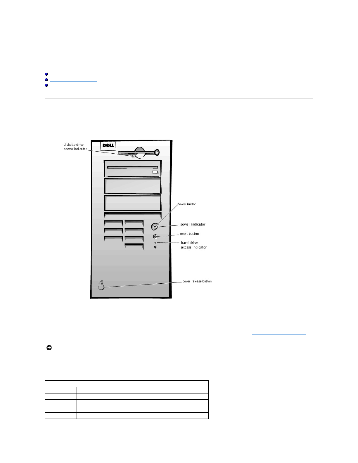
The following illustration shows the controls and indicators located on the front panel of your computer.
Front View
Controls and Indicators
l Reset button — reboots (restarts) the system in a way that reduces stress on system components. Before you push this button, save and close all open
files and application programs to avoid losing data. Then perform an orderly shutdown of the operating system.
If your computer is not responding, you can press the reset button to reboot the system. For more information, see "Recover From a Program That Is
Not Responding" and "Restart a Computer That Is Not Responding."
l Power button — controls the system's AC input power. See the following table for power button functions on systems running Microsoft®Windows®98
SecondEdition(SE),Windows2000,WindowsXP,orWindowsNT®.
NOTICE: If your computer is not responding, turning off power or unplugging the power cord should be done only as a last resort. Doing so can cause
problems with system settings and configuration.
Power Button Functions
Computer Status
Power Button Functions
Off
Push and release to turn the computer on
On
Push and hold for more than 6 seconds to immediately turn the computer off
On
Push and release to attempt an orderly system shutdown
Suspended state
Push and release to bring the system out of the suspended state
Page 3
l Power indicator — contains a light that illuminates in two colors and blinks or remains solid to indicate different states.
l Diskette-drive access indicator — lights when the drive is reading data from, or writing data to, a diskette. Wait until this indicator turns off before you
remove a diskette from the drive.
l Hard-drive access indicator — lights when a hard drive or CD drive is reading data from, or writing data to, the drive.
l Cover release button — releases the computer cover; located on back of chassis.
Back View of Your Computer
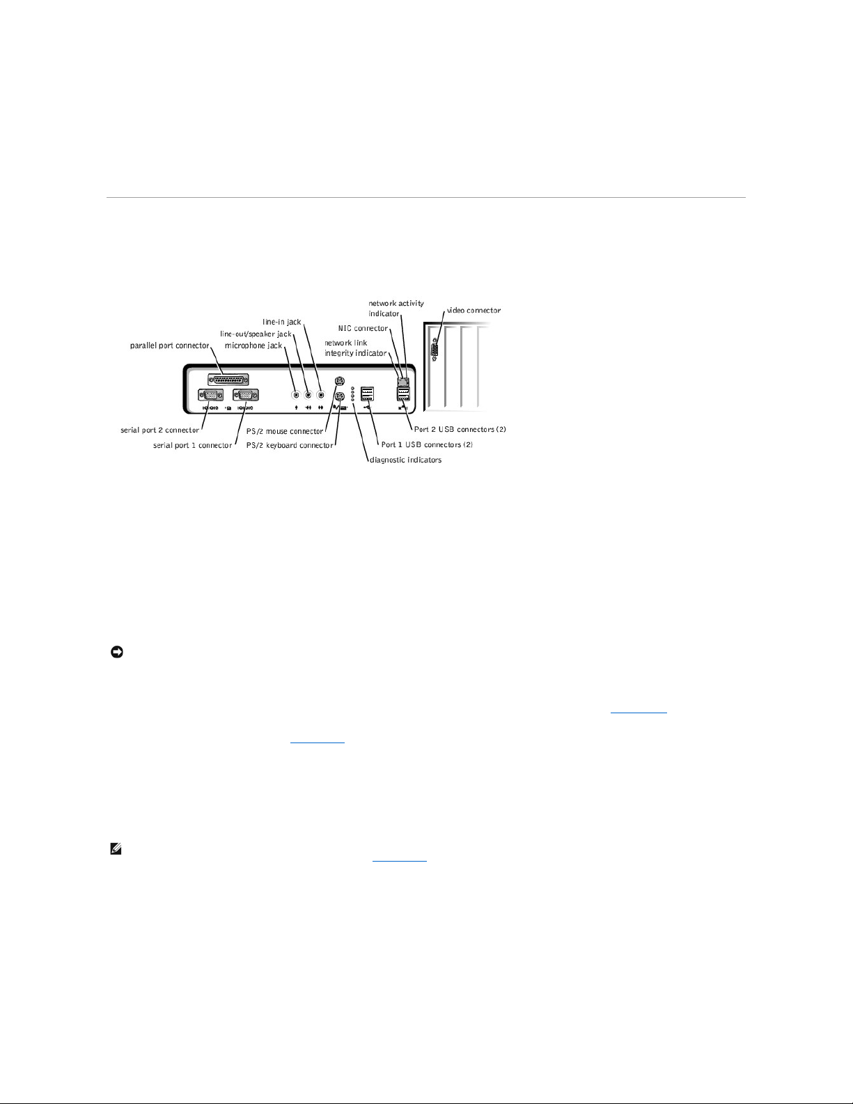
The following illustration shows the connectors and indicators on the back of your computer for attaching external devices.
Back-Panel Connectors and Indicators
Connecting Devices
When you connect external devices to your computer's back panel, follow these guidelines:
l Check the documentation that accompanied the device for specific installation and configuration instructions.
For example, you must connect most devices to a particular input/output (I/O) port or connector to operate properly. Also, external devices like a printer
usually require you to load device drivers before they will work.
l When connecting a Universal Serial Bus (USB) mouse or keyboard, make sure you connect to one of the Port 1 USB connectors.
l Always attach external devices while your computer is turned off. Then turn on the computer before turning on any external devices, unless the
documentation for the device specifies otherwise.
Serial Port Connectors
Default port designations: COM1 for serial port 1 and COM2 for serial port 2. You can reassign the serial port's designation in system setup if you add an
expansion card containing a serial port using this designation.
If you set the system's serial ports to Auto in system setup and add an expansion card containing a serial port configured to a specific designation, the
computer automatically maps (assigns) the integrated ports to the appropriate COM setting as necessary.
Before you add a card with a serial port, check the documentation that accompanied your software to make sure that the software can be mapped to the new
COM port designation.
Parallel Port Connector
Used to connect printers. Default designation: LPT1.
Microphone Jack
Used to attach a standard personal computer microphone. Connect the audio cable from the microphone to the microphone jack.
Line-Out/Speaker Jack
Used to attach computer speakers. This jack is amplified, so speakers with integrated amplifiers are not required. Connect the audio cable from the speakers
to this jack.
Line-In Jack
NOTICE: When you disconnect external devices from the back of the computer, wait 5 seconds after turning off the computer before you reconnect any
devices to avoid possible damage to the system board.
NOTE: The integrated parallel port is automatically disabled if the system detects an installed expansion card containing a parallel port configured to
the same address as specified in the Parallel Port option in system setup.
Page 4

Used to attach record/playback devices such as cassette players, CD players, and VCRs. Connect the line-out cable from any of these devices to the line-in
jack.
PS/2 Mouse Connector
Attach the Personal System/2 (PS/2) mouse cable to the 6-pin mouse connector on the back panel. If your system uses Microsoft Windows 2000, Windows XP,
or Windows NT, Dell installed the necessary mouse drivers on your hard drive.
PS/2 Keyboard Connector
Attach the PS/2 keyboard cable to the 6-pin keyboard connector on the back panel.
USB Connectors
Used to attach USB-compliant devices such as keyboards, mice, printers, and computer speakers to your system.
NIC Connector
The network interface controller (NIC), which includes a Remote Wake Up feature, has the following indicators:
l A yellow network activity indicator flashes when the system is transmitting or receiving network data. (A high volume of network traffic may make this
indicator appear to be in a steady "on" state.)
l A dual-colored network link integrity and speed indicator, which is green when a good connection exists between a 10-megabits per second (Mbps)
network and the NIC, or is orange when a good connection exists between a 100-Mbps network and the NIC. When the orange or green indicator is off,
the computer is not detecting a physical connection to the network.
Network Cable Requirements
The NIC connector attaches an unshielded twisted pair (UTP) Ethernet cable to your system. Press one end of the UTP cable into the NIC connector until the
cable snaps securely into place. Connect the other end to an RJ45 jack wall plate or to an RJ45 port on a UTP concentrator or hub, depending on your network
configuration.
A 100-Mbps network requires Category 5 wiring and connectors. A 10-Mbps network requires Category 3 or Category 5 wiring and connectors.
Video Connector
Used to attach a video graphics array (VGA)-compatible monitor to your system.
Inside Your Computer
The following illustration shows your computer with the covers removed.
Inside the Chassis
NOTE: This connector is similar to the keyboard connector. Make sure you correctly identify the mouse connector before you connect the device.
NOTE: Do not attempt to operate a PS/2 mouse and a USB mouse simultaneously.
NOTE: This connector is similar to the mouse connector. Make sure you correctly identify the keyboard connector before you connect the device.
NOTE: When connecting a USB mouse or keyboard, make sure you connect to one of the Port 1 USB connectors.
NOTE: Do not attempt to operate a PS/2 mouse and a USB mouse simultaneously.
NOTICE: USB devices do not operate with Microsoft Windows NT.
Page 5
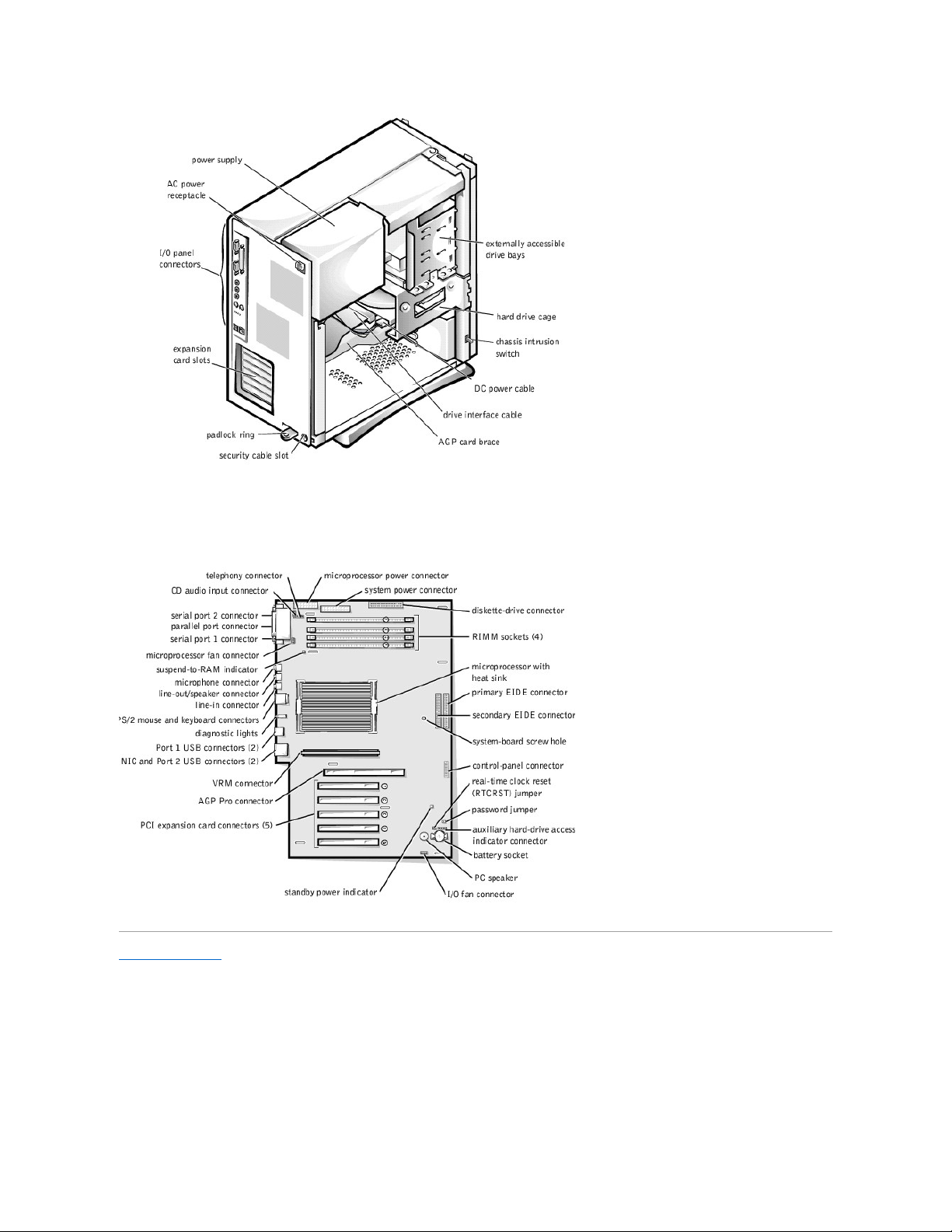
System Board Components
The following illustration shows the system board and the location of its principal connectors and components.
System Board Components
Back to Contents Page
Page 6
Back to Contents Page
Advanced Features
Dell™OptiPlex™GX400SystemUser'sGuide
System Settings
Manageability
Security
Password Protection
Jumper Settings
Installing and Configuring Software
TAPI
Power Management
System Settings
Each time you start your computer, it compares the installed hardware with the system configuration information stored in nonvolatile random-access memory
(NVRAM). If the system detects a discrepancy, it generates an error message for each incorrect configuration setting.
You can use system settings as follows:
l To set user-selectable options such as date and time or system password
l To set the current configuration information such as the amount of memory or type of hard drive installed
You can view the current settings at any time. Dell recommends that you record the information for future reference. If you have a line printer connected to the
parallel port on your computer, you can print the system setup screens by pressing <Print Screen>.
Before you use system setup, you need to know the kind of diskette drive(s) and hard drive(s) installed in your computer. If you are unsure of this information,
see the Manufacturing Test Report that came with your system and is located in the Dell Accessories folder.
Entering System Setup
1. Turn on your system.
2. If your system is already on, restart it.
3. When F2 = Setup appears in the upper-right corner of the screen, press <F2>.
If you wait too long and your operating system begins to load into memory, let the system complete the load operation; then restart the system and try again.
System Setup Screens
The system setup screens display the current configuration information for your computer. Information on the screen is organized into four areas:
l Title — the box at the top of all screens that lists the computer system name.
l Computer data — two boxes below the title box that display your system processor, level 2 (L2) cache, service tag, and the version number of the basic
input/output system (BIOS).
l Options — a scrollable box listing options that define the configuration of your computer, including installed hardware, power conservation, and security
features.
Fields to the right of the option titles contain settings or values. Those that you can change appear bright on the screen. Those that you cannot change
(because they are set by the computer) appear less bright. When <Enter> appears to the right of an option title, press <Enter> to access a pop-up
menu of additional options.
l Key functions — a line of boxes across the bottom of all screens that lists keys and their functions within system setup.
l Help — press <F1> for information in the currently highlighted option.
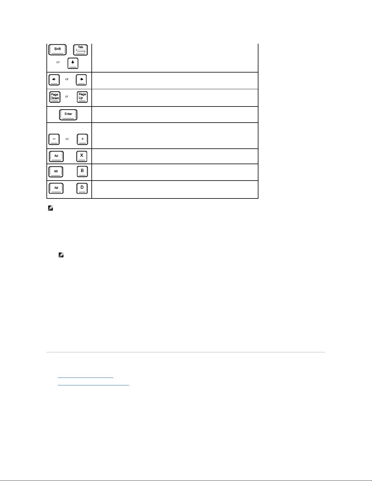
System Setup Navigation Keys
The following table lists the keys you use to view or change information in system setup and to exit setup.
NOTE: To ensure an orderly system shutdown, consult the documentation that accompanied your operating system.
SystemSetupNavigationKeys
Keys
Action
Moves to the next field.
Page 7
Changing the Boot Sequence
The boot sequence allows you to specify the order of the devices from which the system attempts to boot.
1. Press <Enter> to access the Boot Sequence option's pop-up menu.
2. Press the up- and down-arrow keys to move through the list of devices.
3. Press the spacebar to enable or disable a device (enabled devices appear with a check mark).
4. Press plus (+) or minus (–) to move a selected device up or down the list.
Option settings:
l Diskette Drive A: — The system attempts to boot from the diskette drive. If the system finds a diskette in the drive that is not bootable, an error
message appears. If no diskette is in the drive, the system attempts to boot from the next device in the list.
l Hard Drive — The system attempts to boot from the primary hard drive. If the system does not find an operating system on the drive, it attempts to
boot from the next device in the list.
l CD-ROM Device — The system attempts to boot from the CD drive. If the system does not find a CD in the drive or if there is not an operating system
on the CD, the system attempts to boot from the next device in the list.
l MBA (Onboard NIC) — The system prompts you to press <Ctrl><Alt><b> at the Dell logo screen during boot. A menu appears that allows you to select
a method for booting from a network server. If a boot routine is not available from the network server, the system attempts to boot from the next
device in the list.
Manageability
l DellOpenManage™ITAssistant
l Dell OpenManage Client Instrumentation
Dell OpenManage IT Assistant
DellOpenManageITAssistantisthepremierDell™systemsmanagementapplicationforconfiguring,managing,andmonitoringcomputersandotherdevices
on a corporate network. IT Assistant employs the latest remote management technology to provide asset management, configuration management, event
(alert) management, and security management for systems equipped with industry-standard management software. Software of this type is called system
management instrumentation.
IT Assistant supports instrumentation that conforms to the following industry standards:
l Simple Network Management Protocol (SNMP)
Moves to the previous field.
Cycles through the options in a field. In many fields, you can also type the appropriate value.
Scrolls through help information.
Enters the selected field's pop-up options menu.
spacebar or
In the selected field's pop-up options menu, cycles through the options in a field.
Exits system setup without rebooting the system and returns the system to the boot routine.
Exits system setup and reboots the system, implementing any changes you have made.
Resets the selected option to its default setting.
NOTE: For most of the options, any changes you make are recorded but do not take effect until the next time you boot the computer. For a few options
(as noted in the help area), the changes take effect immediately.
NOTE: Write down your current boot sequence in case you want to restore it.
Page 8

l Desktop Management Interface (DMI)
l Common Information Model (CIM)
The instrumentation available for your computer is Dell OpenManage Client instrumentation, which is based on DMI and CIM. For more information on IT
Assistant, see the Dell OpenManage IT Assistant User's Guide available on the Dell website.
Dell OpenManage Client Instrumentation
Dell OpenManage Client Instrumentation is software that enables remote management application programs such as IT Assistant to do the following:
l Access information about your computer, such as how many processors it has and what operating system it is running
l Monitor the status of your computer, such as listening for thermal alerts from temperature probes or hard drive failure alerts from storage devices
l Change the state of your computer, such as updating its BIOS or shutting it down remotely
Dell OpenManage Client Instrumentation can be installed on computers like yours, which, when set up on a network with IT Assistant, are called managed
systems. For more information about Dell OpenManage Client Instrumentation, see the Dell OpenManage Client Instrumentation User's Guide available on the
Dell website.
Security
The computer provides the following methods of physically securing the chassis:
l Chassis intrusion detection
l Security cable slot and padlock ring
Chassis Intrusion Detection
The chassis intrusion monitor can detect whether the chassis is opened. The Chassis Intrusion option in system setup displays the status of the monitor.
1. Enter system setup.
2. Press the down-arrow key to move to the System Security option.
3. Press <Enter> to access the System Security option's pop-up menu.
4. Press the down-arrow key to move to the Chassis Intrusion option.
5. Press the spacebar to select an option setting.
Option settings:
l Enabled (the default) — When the computer cover is removed with this setting, a DMI event is generated, the setting changes to Detected, and the
following message appears during the boot routine at the next system start-up:
Alert! Cover was previously removed.
To reset the Detected setting, enter system setup during the system's power-on self-test (POST). In the Chassis Intrusion option, press the left- or
right-arrow key to select Reset, and then choose Enabled, Enabled-Silent, or Disabled.
l Enabled-Silent — When the computer cover is removed with this setting, a DMI event is generated and the setting changes to Detected, but the alert
message does not appear during the boot sequence at the next system start-up.
l Disabled — No intrusion monitoring occurs and no messages appear.
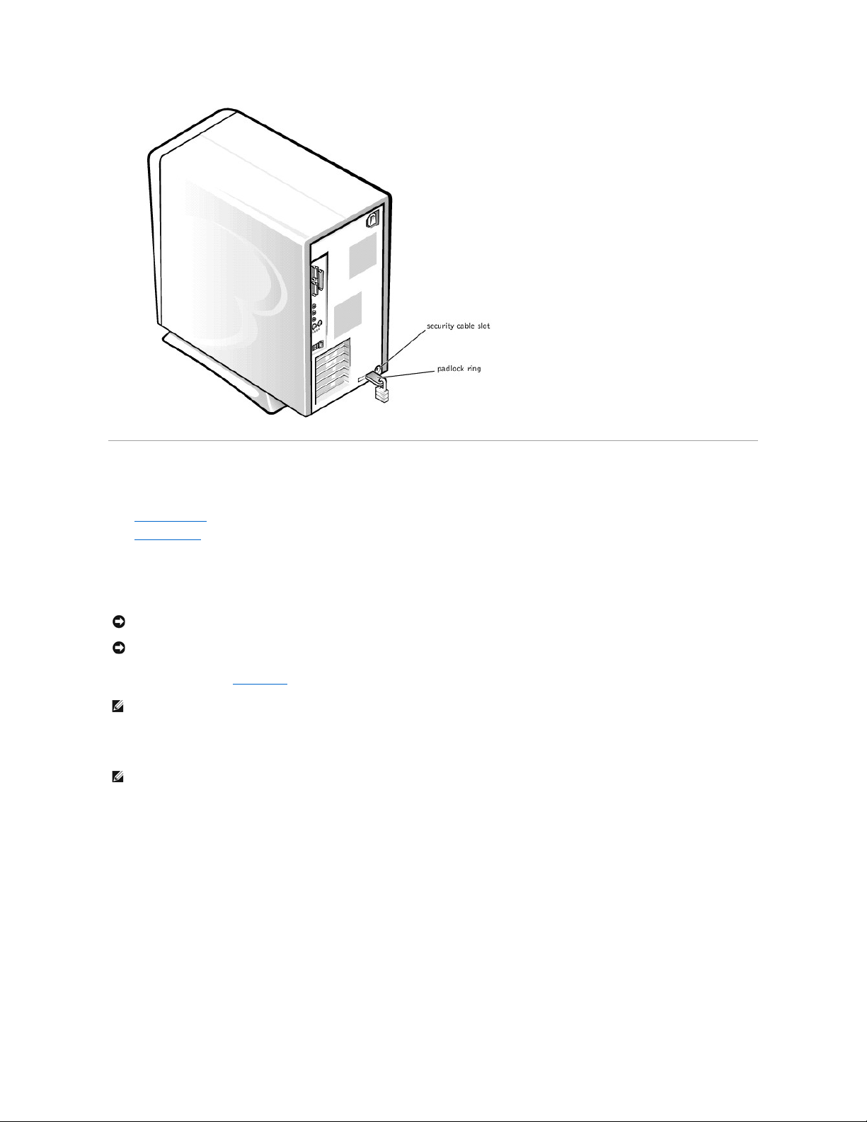
Security Cable Slot and Padlock Ring
These features allow you to attach commercially available antitheft devices (see the following figure). To prevent unauthorized removal of your computer, loop
the galvanized security cable around an immovable object, insert the attached locking device into the security cable slot on the back of your computer, and
lock the device with the key provided.
Security Features on the Computer Chassis
NOTE: When the setup password is enabled, you must know the setup password before you can reset the Chassis Intrusion option.
NOTE: Before you purchase an antitheft device, make sure it works with the cable slot on your computer.
Page 9
Password Protection
The computer provides the following types of password protection:
l System password
l Setup password
System Password
System passwords allow only those who know the password to have full use of the system. Your Dell system does not have the system password feature
enabled when you receive it.
System Password settings in system setup:
l Enabled — a system password is assigned
l Disabled — system password feature is disabled by a jumper setting on the system board
l Not Enabled — no system password is assigned and the password jumper on the system board is in the enabled position (its default setting)
Assigning a System Password
1. Verify that Password Status is set to Unlocked in system setup.
2. Highlight System Password and then press the left- or right-arrow key.
The option heading changes to Enter Password, followed by an empty 32-character field in square brackets.
3. Type your new system password.
You can use up to 32 characters.
As you press each character key (or the spacebar for a blank space), a placeholder appears in the field. The password assignment operation recognizes
keys by their location on the keyboard, without distinguishing between lowercase and uppercase characters. For example, if you have an M in your
password, the system recognizes either M or m as correct.
Certain key combinations are not valid. If you enter one of these combinations, the speaker emits a beep.
To erase a character when entering your password, press <Backspace> or the left-arrow key.
NOTICE: Although passwords provide security for the data on your system, they are not foolproof. If your data requires more security, it is your
responsibility to obtain and use additional forms of protection, such as data encryption programs.
NOTICE: If you leave your system running and unattended without having a system password assigned, or if you leave your computer unlocked so that
someone can disable the password by changing a jumper setting, anyone can access the data stored on your hard drive.
NOTE: You cannot change or enter a new system password if either of the following two options is displayed.
NOTE: You can only assign a system password when System Password is set to Not Enabled.
Page 10

4. Press <Enter>.
If the new system password is less than 32 characters, the whole field fills with placeholders. Then the option heading changes to Verify Password,
followed by another empty 32-character field in square brackets.
5. To confirm your password, type it a second time and press <Enter>.
The password setting changes to Enabled. Your system password is now set; you can exit system setup and begin using your system. Password
protection takes effect when you reboot the system by pressing the reset button or by turning the system off and then on again.
Using Your System Password
When you turn on your system or press the reset button, or when you reboot the system by pressing the <Ctrl><Alt><Del> combination, the following prompt
appears on the screen when Password Status is set to Unlocked:
Type in the password and
- press <ENTER> to leave password security enabled.
- press <CTRL><ENTER> to disable password security.
Enter password:
If Password Status is set to Locked, the following prompt appears:
Type the password and press <Enter>.
If you enter a wrong or incomplete system password, the following message appears on the screen:
** Incorrect password. **
Enter password:
If you again enter an incorrect or incomplete system password, the same message appears on the screen. The third and subsequent times you enter an
incorrect or incomplete system password, the system displays the following message:
** Incorrect password. **
Number of unsuccessful password attempts: 3
System halted! Must power down.
Even after your system is turned off and on, the previous message is displayed each time an incorrect or incomplete system password is entered.
Deleting or Changing an Existing System Password
To delete or change an existing system password, perform the following steps:
1. Enter system setup, and verify that Password Status is set to Unlocked.
2. Reboot your system to force it to prompt you for a system password.
3. When prompted, type the system password.
4. Press <Ctrl><Enter> to disable the existing system password, instead of pressing <Enter> to continue with the normal operation of your system.
5. Confirm that Not Enabled is displayed for the System Password option.
If Not Enabled appears in the System Password option, the system password has been deleted. If you want to assign a new password, continue to
step 6. If Not Enabled is not displayed for the System Password option, press <Alt><B> to reboot the system, and then repeat steps 3 through 5.
6. To assign a new password, follow the procedure in "Assigning a System Password."
Setup Password
Setup passwords allow only those who know the password to have full use of system setup. Your Dell system does not have the setup password feature
enabled when you receive it.
Setup Password options in system setup:
l Enabled — does not allow assignment of setup passwords; users must enter a setup password to make changes to system setup
l Not Enabled — allows assignment of setup passwords; password feature is enabled but no password is assigned
Assigning a Setup Password
1. Enter system setup, and verify that Setup Password is set to Not Enabled.
2. Highlight Setup Password and press the left- or right-arrow key.
The system prompts you to enter and verify the password. If a character is illegal for password use, the system emits a beep.
NOTE: To escape from the field without assigning a system password, press <Tab> or the <Shift><Tab> combination to move to another field, or
press <Esc> at any time before completing step 5.
NOTE: If you have assigned a setup password, the system accepts your setup password as an alternate system password.
NOTE: You can use Password Status in conjunction with System Password and Setup Password to further protect your system from unauthorized
changes.
Page 11

3. Type in and then verify the password.
After you verify the password, the Setup Password setting changes to Enabled. The next time you attempt to enter system setup, the system prompts
you for the setup password.
A change to Setup Password becomes effective immediately (rebooting the system is not required).
Operating Your System With a Setup Password Enabled
When you start system setup, the Setup Password option is highlighted, prompting you to type the password.
If you do not enter the correct password, the system lets you view, but not modify, system setup options.
Deleting or Changing an Existing Setup Password
To change an existing setup password, you must know the setup password.
1. Enter system setup.
2. If you have already assigned a setup password, type it at the prompt.
3. Highlight Setup Password and press the left- or right-arrow key to delete the existing setup password.
The setting changes to Not Enabled.
4. If you want to assign a new setup password, perform the steps in "Assigning a System Password."
Disabling a Forgotten Password
1. Turn off the computer and peripherals, disconnect them from their electrical outlets, wait at least 5 seconds, and then remove the computer cover.
2. Remove the jumper plug from the PSWD jumper to disable the password feature.
See "Jumper Settings" to locate the password jumper (labeled "PSWD") on the system board.
3. Replace the computer cover.
4. Reconnect your computer and peripherals to an electrical outlet, and then turn them on.
This erases the existing password(s).
5. Enter system setup and verify that the password is disabled. Proceed to step 6 if you want to assign a new password.
6. Remove the computer cover.
7. Replace the PSWD jumper plug.
8. Replace the computer cover and reconnect the computer and peripherals to an electrical outlet and turn them on.
Booting your system with the PSWD jumper installed reenables the password feature. When you enter system setup, both password options appear as
Not Enabled, meaning that the password feature is enabled but that no password is assigned.
9. Assign a new system and/or setup password.
Jumper Settings
The following figure shows the location of the jumpers on the system board.
System Board Jumpers
NOTE: The setup password can be the same as the system password.
NOTE: If the two passwords are different, the setup password can be used as an alternate system password. However, the system password cannot
be used in place of the setup password.
NOTE: You can use Password Status in conjunction with System Password and Setup Password to further protect your system from unauthorized
changes.
NOTICE: This process erases both the system and setup passwords.
CAUTION: Before you remove the computer cover, see "Safety First—For You and Your Computer."
NOTE: Before you assign a new system and/or setup password, you must replace the PSWD jumper plug to reenable the password feature.
CAUTION: Before you remove the computer cover, see "Safety First—For You and Your Computer."
Page 12
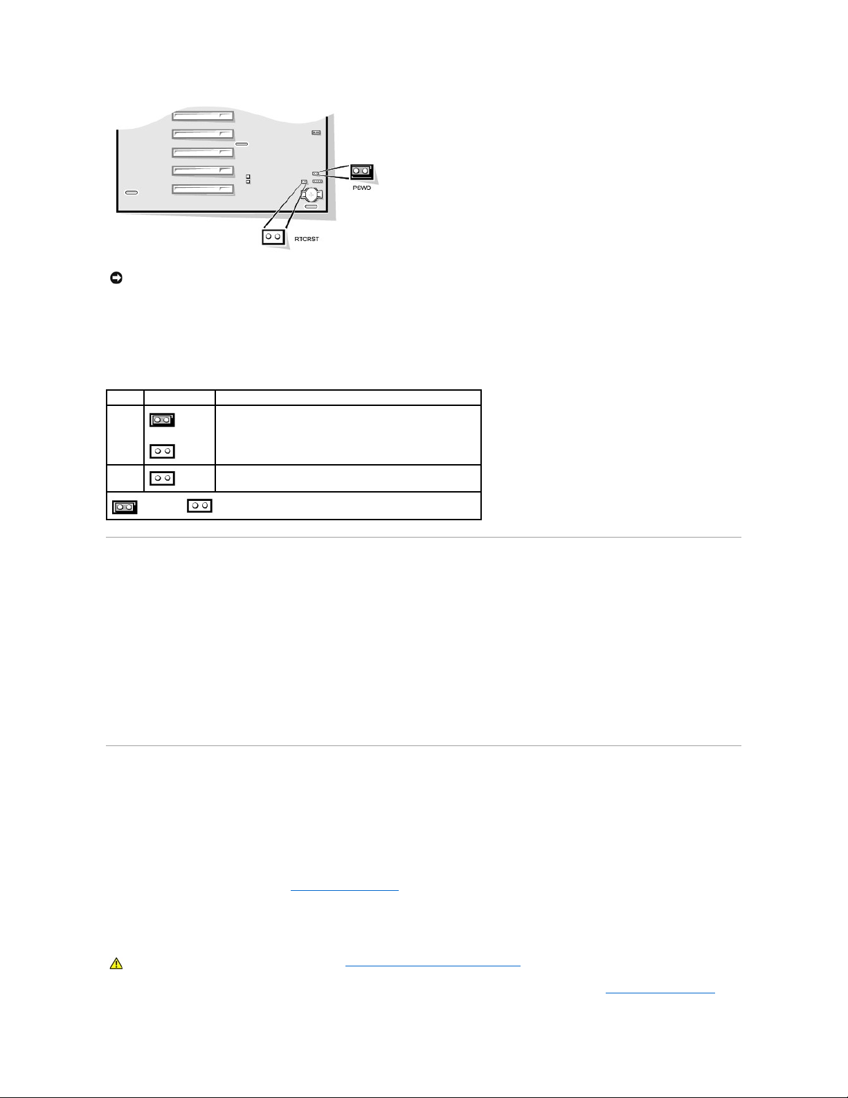
To change a jumper setting, pull the plug off its pin(s) and carefully fit it down onto the pin(s) indicated
The following table lists the system board jumpers and their settings.
Installing and Configuring Software
When you obtain software, check it for viruses with virus-scanning software before installing it on your computer's hard drive. Viruses, which are pieces of
code that can replicate themselves, can quickly use all available system memory, damage or destroy data stored on the hard drive, and permanently affect the
performance of the programs they infect. Several commercial virus-scanning programs are available for purchase, and most bulletin board services (BBSs)
archive freely distributed virus-scanning programs that you can download with a modem.
Before you install a program, read its documentation to learn how the program works, what hardware it requires, and what its defaults are. A program usually
includes installation instructions in its accompanying documentation and a software installation routine on its program diskette(s) or CD(s).
The software installation routine assists you in transferring the appropriate program files to your computer's hard drive. Installation instructions may provide
details about how to configure your operating system to successfully run the program. Always read the installation instructions before running a program's
installation routine. You may be instructed to modify some operating system start-up files, such as config.sys and autoexec.bat, or the installation routine
may modify start-up files automatically.
When you run the installation routine, be prepared to respond to prompts for information about how your computer's operating system is configured, what
type of computer you have, and what peripherals are connected to your computer.
TAPI
Telephony Application Programming Interface (TAPI) enables Windows-based applications to operate with a wide variety of telephony devices, including voice,
data, fax, video, and so forth. TAPI applications require a TAPI service provider (TSP), which is a software driver that allows TAPI applications to communicate
with different types of TAPI hardware.
Microsoft®Windows®2000, Windows XP, and Windows NT®provide a TSP called Unimodem, which is a "universal" modem service provider that supports a
wide range of commonly used modems. For more information on Unimodem, see your Windows documentation. When using a TAPI device other than a
modem, such as a Private Branch Exchange (PBX) or a voice processing card, you will need a TSP provided by the manufacturer of the device.
The TAPI system board connector uses a 4-pin cable to interface your internal TAPI-compliant expansion card with the audio system in your computer. To
locate the TAPI system board connector, see "System Board Components." TAPI-compliant cards using the standard TAPI connector are supported. For
example, you can connect your modem to the TAPI connector and then use your audio speakers and microphone as a speakerphone. The microphone carries
your voice into the computer and then through the TAPI system board connector to your modem card. The caller's voice enters through the modem card to the
TAPI system board connector and then out to the speakers. You can also use this configuration to record and play sound files over the phone.
Installing a TAPI Device
1. Turn off the computer and peripherals, disconnect them from their electrical outlets, wait at least 5 seconds, and then remove the computer cover.
NOTICE: Make sure your system is turned off before you change a jumper setting. Otherwise, damage to your system or unpredictable results may
occur.
System-Board Jumper Settings
Jumper
Setting
Description
PSWD
(default)
Password features are enabled.
Password features are disabled.
RTCRST
Real-time clock reset. Can be used for troubleshooting purposes.
jumpered unjumpered
CAUTION: Before you perform this procedure, see "Safety First— For You and Your Computer."
Page 13

2. Install the TAPI-compliant expansion card.
See the manufacturer's documentation for more information.
3. Rotate the power supply away from the system board.
4. Connect the 4-pin TAPI cable to the TAPI system board connector.
To locate the TAPI connector on the system board, see "System Board Components."
5. Connect the 4-pin TAPI cable to the TAPI expansion card connector.
To locate the TAPI connector on the expansion card, see the manufacturer's documentation.
6. Rotate the power supply back into position, making sure that the securing tab snaps into place.
7. Replace the computer cover.
8. Reconnect your computer and peripherals to an electrical outlet, and then turn them on.
9. Install the appropriate TSP for the TAPI device.
See the manufacturer's documentation and your Windows documentation for more information.
Installing a TAPI Sound Card
You can install a TAPI-compliant sound card that has a standard TAPI connector. For example, you can connect your modem to the TAPI sound card connector
and then use the audio capabilities as a speakerphone.
1. Turn off the computer and peripherals, disconnect them from their electrical outlets, wait at least 5 seconds, and then remove the computer cover.
2. Install the TAPI-compliant sound card.
See the manufacturer's documentation for more information.
3. Enter system setup, select Integrated Devices and change the setting for Sound to Off.
4. Connect external audio devices to the sound card's connectors. Do not connect external audio devices to the microphone, line-out, or line-in connectors
on the system back panel (see "Back-Panel Connectors and Indicators").
5. Connect the 4-pin TAPI cable to the TAPI sound card connector.
To locate the TAPI connector on the sound card, see the manufacturer's documentation.
6. Connect the 4-pin TAPI cable to the TAPI expansion card connector.
To locate the TAPI connector on the expansion card, see the manufacturer's documentation.
7. Replace the computer cover.
8. Reconnect your computer and peripherals to an electrical outlet, and then turn them on.
9. Install the appropriate TSP for the TAPI devices.
See the manufacturer's documentation and your Windows documentation for more information.
Power Management
Your computer can be set to use less power when you are not working. You control the power usage through the operating system (OS) installed on your
computer and certain option settings in system setup. These periods of reduced power are called "sleep states."
l Standby. In this sleep state, power to most components is reduced or turned off. However, system memory remains active.
This state is not supported by Windows NT 4.0.
l Hibernate. This sleep state reduces power consumption to a minimum by writing all data in system memory to a hard drive and then removing system
power. Waking up from this state restarts the computer, and the memory contents are restored. Operation then resumes where the system left off
when it entered the hibernation state.
This state is supported by Windows 2000 and Windows XP only.
l Shutdown. This sleep state removes all power from the system except a small auxiliary amount. As long as the computer remains connected to an
electrical outlet, it can be automatically or remotely started. For example, the Auto Power On feature allows the computer to automatically start at a time
you specify in system setup. Also, your network administrator can remotely start your computer using a power management event (PME) such as access
through a network connection (Wakeup On LAN).
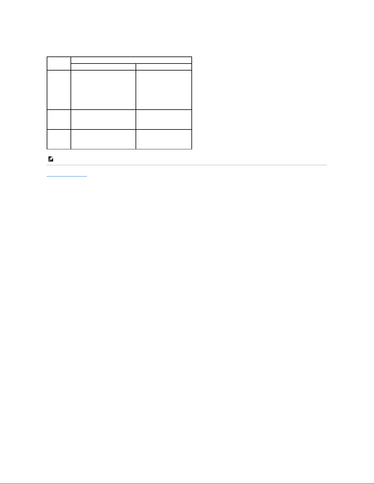
The following table lists the sleep states available for each operating system as well as the methods you can use to "wake up" from each state.
CAUTION: Before you perform this procedure, see "Safety First— For You and Your Computer."
NOTE: All components installed in the computer must support this feature and have the appropriate drivers loaded to enter hibernation. For more
information, see the manufacturer's documentation for each component.
Page 14
Back to Contents Page
Power Management
Sleep State
Wake-Up Methods
Windows 2000 and XP
Windows NT 4.0
Standby
l Press the power button
l Auto power on
l PME
l Move or click the PS/2 mouse
l Move or click the USB mouse
l Type on the PS/2 keyboard
l Type on the USB keyboard
l USB device activity
Not supported
Hibernate
l Press the power button
l Auto power on
l PME
Not supported
Shutdown
l Press the power button
l Auto power on
l PME
l Press the power button
l Auto power on
l PME
NOTE: For more information on power management, see your operating system documentation.
Page 15
Back to Contents Page
Installing Upgrades
Dell™OptiPlex™GX400SystemUser'sGuide
Computer Cover
Power Supply
Front Panel
System Memory
Disk Drives and Media
AGP Card Brace
Expansion Cards
Microprocessor
VRM
System Battery
Computer Cover
Removing the Computer Cover
1. Turn off the computer and peripherals, and disconnect them from their electrical outlets.
2. If installed, remove the padlock from the padlock ring on the back panel.
3. Remove the computer cover.
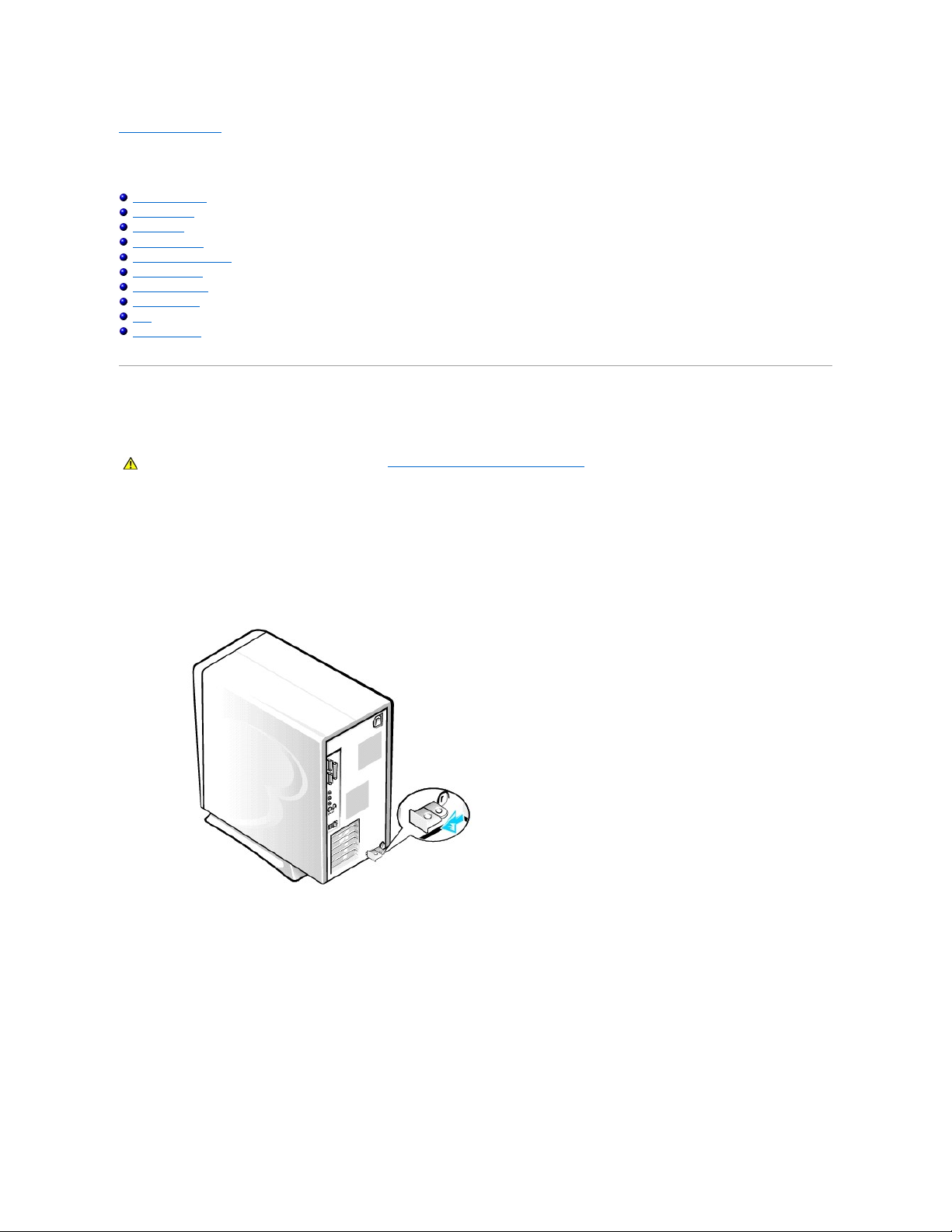
Perform the following steps:
a. Face the back of the computer and slide the outer padlock ring to the left to unlock the cover release mechanism (see the following figure).
Chassis Cover Release Mechanism
b. Press the cover release button located at the bottom-left corner of the front panel (see the following figure).
c. Rotate the bottom of the cover outward, away from the chassis.
Removing the Chassis Cover
CAUTION: Before you perform this procedure, see "Safety First— For You and Your Computer."
Page 16
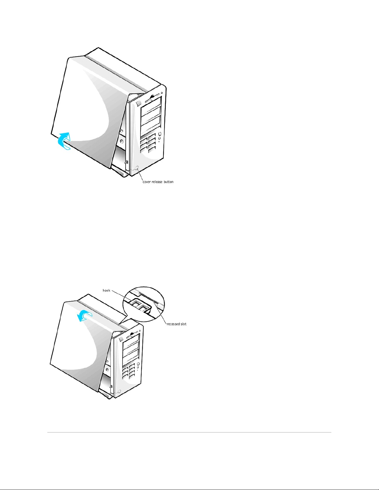
d. Lift the cover away from the chassis.
e. Turn the computer on its right side before you begin working inside the chassis.
Replacing the Computer Cover
1. Check all cable connections and fold cables out of the way so that they do not catch on the computer cover. Ensure that cables are not routed over the
drive cage—they will prevent the cover from closing properly.
2. Ensure that no tools or extra parts (including screws) are left inside the computer chassis.
3. Replace the computer cover.
Perform the following steps:
a. Hold the cover at a slight angle as shown in the following figure. While aligning the top of the cover with the top of the chassis, insert the three
hooks on the cover into the three recessed slots on the computer chassis.
Replacing the Computer Cover
b. Rotate the cover downward toward the bottom of the chassis. With both hands, press against the bottom edge of the cover to ensure that the
securing hooks at the bottom of the cover click into place.
c. Slide the two parts of the padlock ring together to lock the cover release mechanism.
Page 17

Power Supply
To access some of the components on the system board, you may need to rotate the system power supply out of the way.
1. Turn off the computer and peripherals, disconnect them from their electrical outlets, wait at least 5 seconds, and then remove the computer cover.
2. Make sure the AC power cable is disconnected from the AC power receptacle on the back of the power supply (see the following figure).
Rotating the Power Supply in a Chassis
3. Free the power supply from the securing tab by pressing the tab labeled "RELEASE." Then rotate the power supply upward until it locks in its extended
position.
When you have finished accessing components on the system board, rotate the power supply back to its original position until the release tab snaps into the
securing tab.
Front Panel
To remove the front panel, you first must remove the computer cover. With the cover removed, release the front panel by pressing the green front-panel
release button marked with the icon (see the following figure).
Removing the Front Panel
CAUTION: Before you perform this procedure, see "Safety First—For You and Your Computer."
CAUTION: Before you perform this procedure, see "Safety First— For You and Your Computer."
Page 18
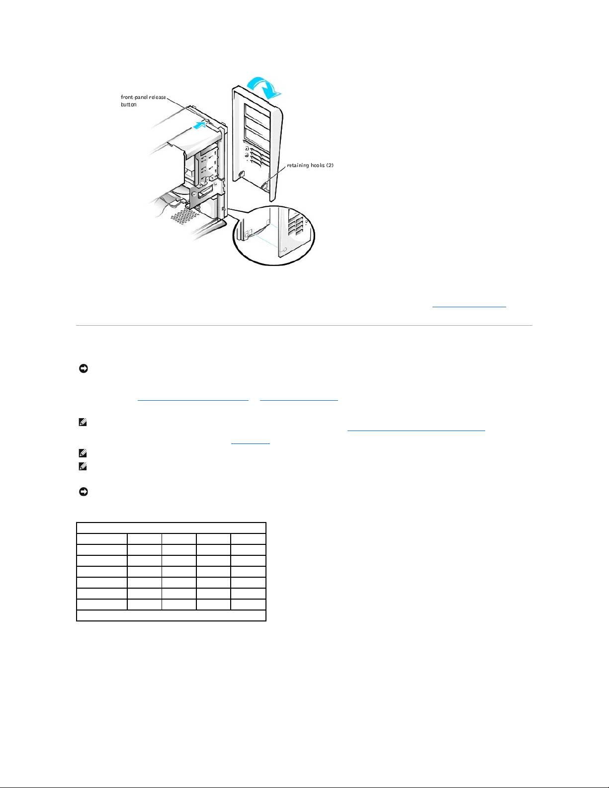
While pressing the front-panel release button, rotate the top of the panel outward, away from the chassis. Lift the panel away from the chassis.
To replace the front panel, fit the two front-panel retaining hooks into the recessed slots at the bottom of the chassis (see "Removing the Front Panel"). Then
rotate the top of the panel toward the chassis until the front-panel latches snap into the tabs on the front panel.
System Memory
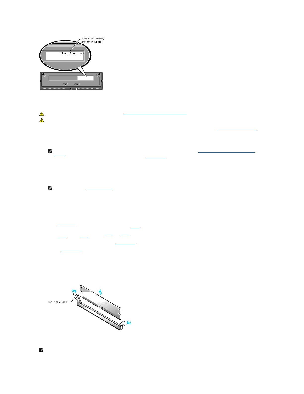
Your computer supports Rambus dynamic random-access memory (RDRAM) Rambus in-line memory modules (RIMMs) in 64-, 128-, 256-, and 512-megabyte
(MB) capacities (see "Sample Memory Module Configurations"). "System Board Components" in "About Your Computer" shows the location of the four RIMM
sockets on the system board. Sockets that do not contain a RIMM must contain Rambus continuity RIMMs (CRIMMs).
RIMM Label Showing Number of Memory Devices
NOTICE: Before you install new memory modules, download the most recent BIOS for your computer from the Dell Support website at
support.dell.com.
NOTE: To reach the maximum 2-gigabyte (GB) memory total, you must install four 512-MB RIMMs that each have a maximum of 16 memory devices. The
system supports no more than a total of 64 memory devices on all installed RIMMs. See "RIMM Label Showing Number of Memory Devices" for the
location of the label on the RIMM that identifies the number of memory devices it contains. You can also determine the number of memory devices
installed through the System Memory option in system setup.
NOTE: The system does not support RIMMs with six memory devices.
NOTE: All four RIMM slots must be occupied either by a RIMM or a CRIMM and must be upgraded in matched pairs of identical capacity in slots 1 and 2 or
slots 3 and 4. Mixed RIMM pairs provide a capacity equal to the sum of the four RIMMs; mixed pairs of RIMMs that provide error checking and correction
(ECC) and non-ECC will all function as non-ECC.
NOTICE: Be sure to install a RIMM in socket 1 first (closest to the processor) before installing a RIMM in socket 2.
Sample Memory Module Configurations
Total Memory
Socket 1
Socket 2
Socket 3
Socket 4
128 MB
64 MB
64 MB
CRIMM
CRIMM
256 MB
64 MB
64 MB
64 MB
64 MB
256 MB
128 MB
128 MB
CRIMM
CRIMM
512 MB*
128 MB
128 MB
128 MB
128 MB
512 MB*
256 MB
256 MB
CRIMM
CRIMM
1024 MB
256 MB
256 MB
256 MB
256 MB
*512-MB RIMM technology will be supported when it is available.
Page 19
Upgrading System Memory
1. Turn off the computer and peripherals, disconnect them from their electrical outlets, wait at least 5 seconds, and then remove the computer cover.
2. Rotate the power supply away from the system board.
3. If necessary, remove any modules (RIMMs or CRIMMs) that occupy sockets in which you plan to install the upgrade modules.
4. Install the upgrade RIMMs.
5. Rotate the power supply back into position, making sure that the securing tab snaps into place.
6. Replace the computer cover, reconnect the computer and peripherals to their electrical outlets, and turn them on.
ALERT! Cover was previously removed.
The system detects that the new memory does not match the existing system configuration information and generates the following message:
The amount of system memory has changed.
Strike the F1 key to continue, F2 to run the setup utility
7. Enter system setup, and check the value for System Memory. The system should have already changed the value of System Memory to reflect the
newly installed memory. If the new total is correct, skip to step 9.
8. If the memory total is incorrect, repeat step 1 and step 2. Check the installed modules to ensure that they are seated properly in their sockets. Then
repeat step 5 through step 7.
9. When the System Memory total is correct, exit system setup.
10. Run the Dell Diagnostics to verify that the memory modules are operating properly.
Removing a Memory Module
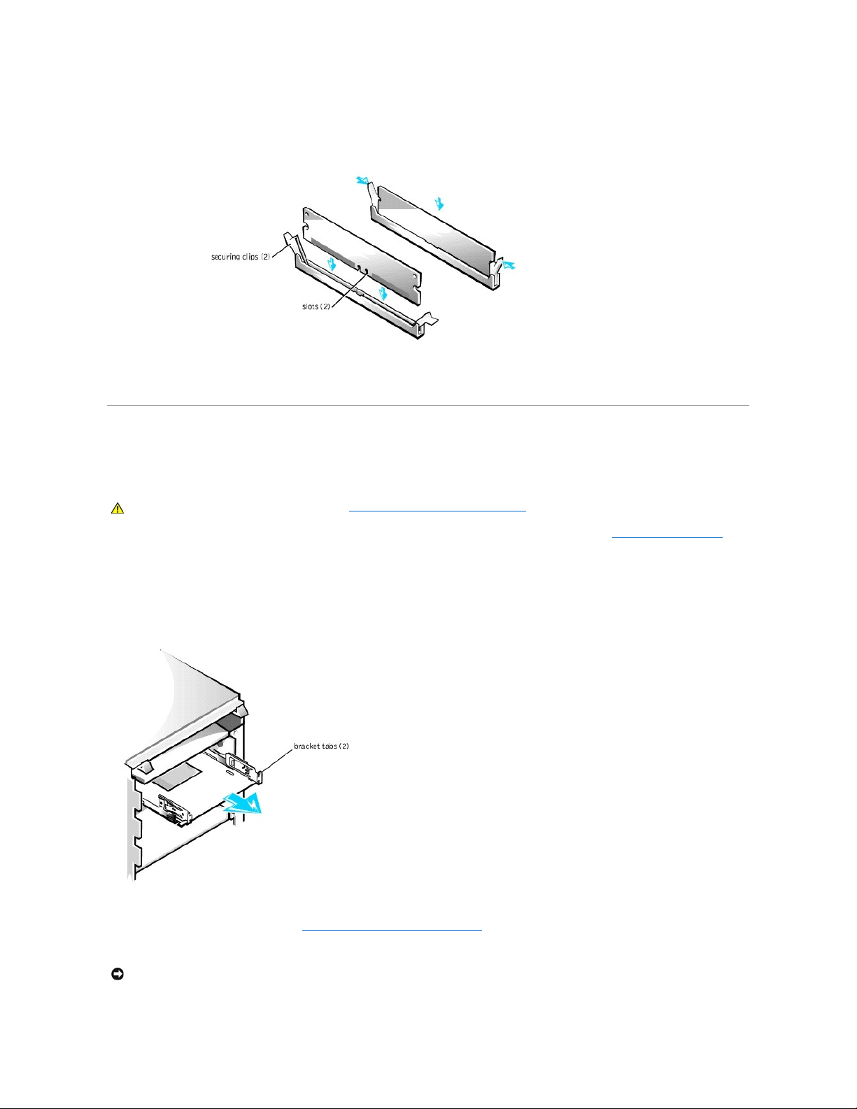
1. Press the securing clips at each end of the socket outward simultaneously until the module pops out slightly from the socket (see the following figure).
Removing a Memory Module
2. Lift the module away from the socket.
CAUTION: Before you perform this procedure, see "Safety First— For You and Your Computer."
CAUTION: RIMMs can get very hot during system operation. Be sure that the RIMMs have had sufficient time to cool before you touch them.
NOTE: The system supports no more than a total of 64 memory devices on all installed RIMMs. See "RIMM Label Showing Number of Memory
Devices" for the location of the label on the RIMM that identifies the number of memory devices it contains. You can also determine the number of
memory devices installed through the System Memory option in system setup.
NOTE: If enabled, the Chassis Intrusion option will cause the following message to be displayed at the next system start-up:
NOTE: If you remove a module (RIMM or CRIMM), you must install another module in the empty socket before turning on the computer.
Page 20
Installing a Memory Module
1. Press the securing clips at each end of the socket outward until they snap open (see the following figure).
Installing a Memory Module
2. Align the slots on the bottom of the module with the two ridges inside the socket.
3. Press the module straight down into the socket until the securing clips snap into place at the ends of the module.
Disk Drives and Media
Installing a CD, ZIP, or Other Externally Accessible Drive
in the Chassis
1. Turn off the computer and peripherals, disconnect them from their electrical outlets, wait at least 5 seconds, and then remove the computer cover.
2. Rotate the power supply away from the system board.
3. Remove the front panel.
4. Remove the drive bracket from the chassis drive bay you want to use.
Squeeze together the metal tabs that extend from each side of the drive bracket, and pull the bracket out of the bay (see the following figure).
Removing the Drive Bracket
If a drive is already installed in the bay and you are replacing it, disconnect the DC power cable and interface cable from the back of the drive before
removing the bracket from the bay. To remove the old drive from the bracket, turn the drive/bracket assembly upside down and remove the four screws
that secure the drive to the bracket (see "Attaching the Drive Bracket to the New Drive").
5. Unpack the drive and prepare it for installation.
See the documentation that accompanied the drive to verify that the drive is configured for your computer. Change any settings necessary for your
CAUTION: Before you perform this procedure, see "Safety First— For You and Your Computer."
NOTICE: Ground yourself by touching an unpainted metal surface on the back of the computer.
Page 21
configuration.
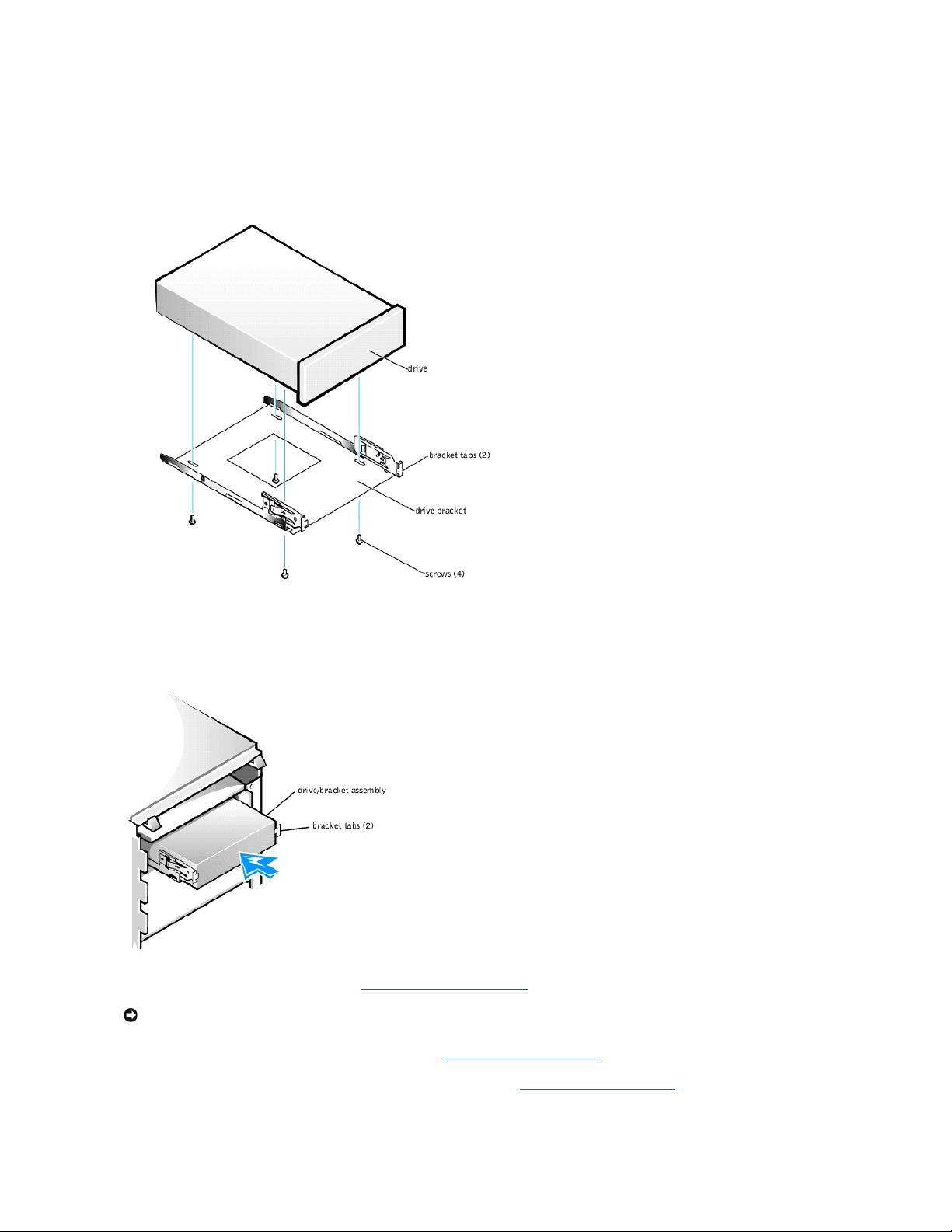
6. Attach the new drive to the drive bracket.
Turn the drive upside down, and fit the bracket on the drive so that the screw holes align. To ensure proper installation, all screw holes should be
aligned and the tabs on the front of the bracket should be flush with the front of the drive (see the following figure).
Attaching the Drive Bracket to the New Drive
To further ensure proper positioning of the drive in the chassis, insert and tighten all four screws in the order in which the holes are numbered (the holes
are marked "1" through "4").
7. Slide the new drive/bracket assembly into the drive bay until both drive bracket tabs snap securely into place (see the following figure).
Installing the Drive Bracket in the Chassis
8. Connect the interface cable for the drive (see "Attaching Drive Cables in the Chassis").
a. If you are installing an enhanced integrated drive electronics (EIDE) device, make sure that the interface cable is properly connected to the EIDE
connector on the system board. For more information, see "EIDE Device Installation Guidelines."
b. If you are installing a small computer system interface (SCSI) device, make sure that the SCSI interface cable is properly connected to the
interface connector on the SCSI controller board. For more information, see "SCSI Device Installation Guidelines."
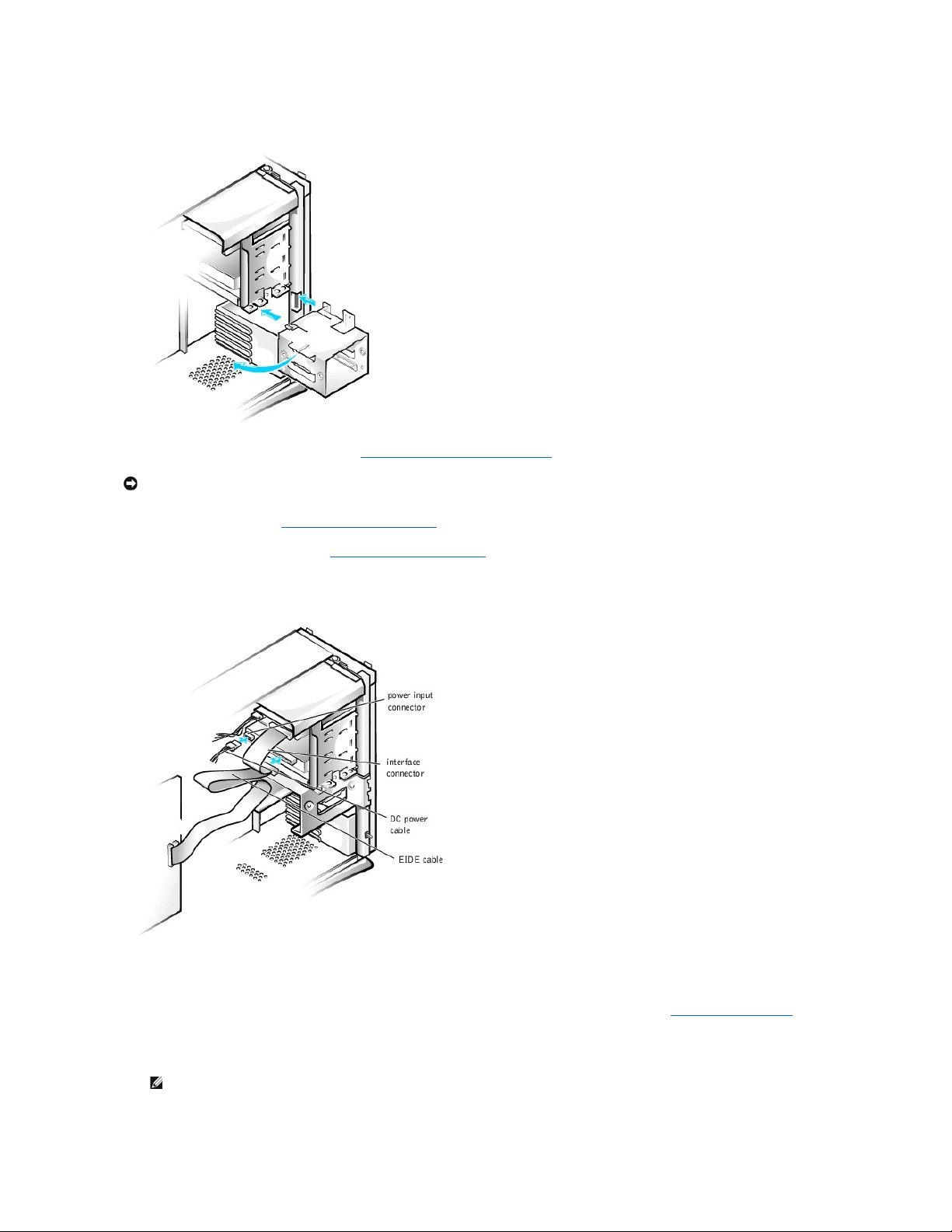
9. Connect a DC power cable to the power input connector on the back of the drive (see the following figure).
NOTICE: To avoid possible damage, you must match the colored strip on the interface cable with pin 1 on both the drive and system board connectors.
Page 22
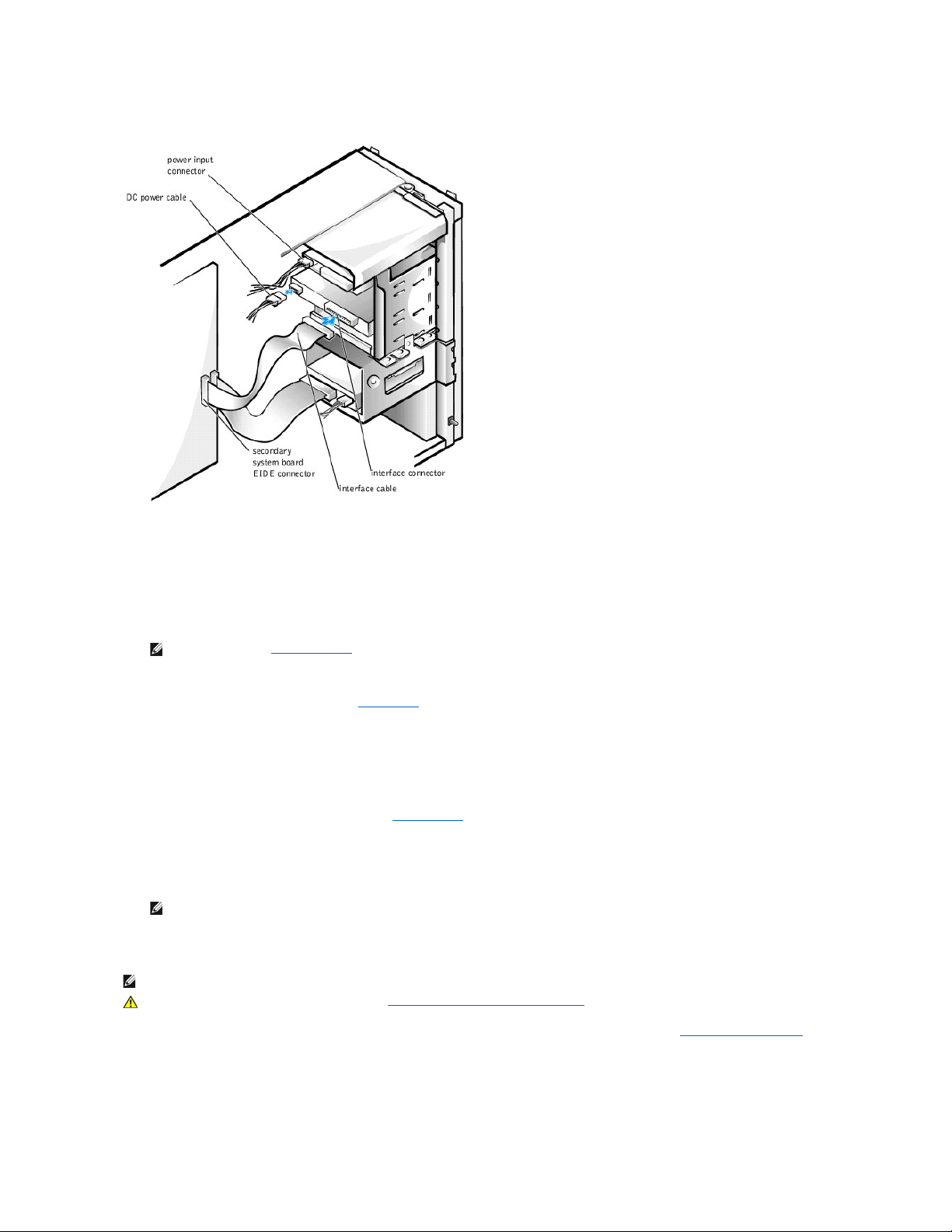
Attaching Drive Cables in the Chassis
10. Ensure that all cables are firmly connected. Fold cables out of the way to provide airflow for the fan and cooling vents.
11. If the chassis drive bay was previously empty, remove the corresponding insert from the front panel.
Hold the front panel with the outside facing you. Press the ends of the insert with your thumbs until the insert snaps free of the front panel.
12. Replace the front panel.
13. Replace the computer cover, reconnect the computer and peripherals to their electrical outlets, and turn them on.
ALERT! Cover was previously removed.
14. If the drive you installed is a hard drive, enter system setup, and update the drive settings.
After you update the system settings, exit system setup and reboot the computer.
15. If the device you installed is a hard drive, partition and logically format the drive before proceeding to the next step.
See the operating system's documentation for instructions.
16. Test the drive to verify that it is operating properly.
l If the drive you installed is a hard drive, run the Dell Diagnostics to test the drive.
l For other types of drives, see the drive's documentation for information on testing the drive.
17. If the drive you installed is the primary hard drive, install the operating system on the drive.
See the operating system's documentation for instructions.
Installing a Hard Drive in the Chassis
1. Turn off the computer and peripherals, disconnect them from their electrical outlets, wait at least 5 seconds, and then remove the computer cover.
2. Rotate the power supply away from the system board.
3. Remove the front panel.
4. Remove the drive bracket from the chassis.
Pull the drive door forward and down until the hard-drive bracket is ejected halfway out of the chassis (see the following figure). Then grasp the bracket
NOTE: If enabled, the Chassis Intrusion option will cause the following message to be displayed at the next system start-up:
NOTE: Tape drives sold by Dell come with their own operating software and documentation. After you install a tape drive, refer to the
documentation that came with the drive for instructions on installing and using the tape drive software.
NOTE: If you are replacing a hard drive that contains data you want to keep, be sure to back up your files before you begin this procedure.
CAUTION: Before you perform this procedure, see "Safety First— For You and Your Computer."
Page 23
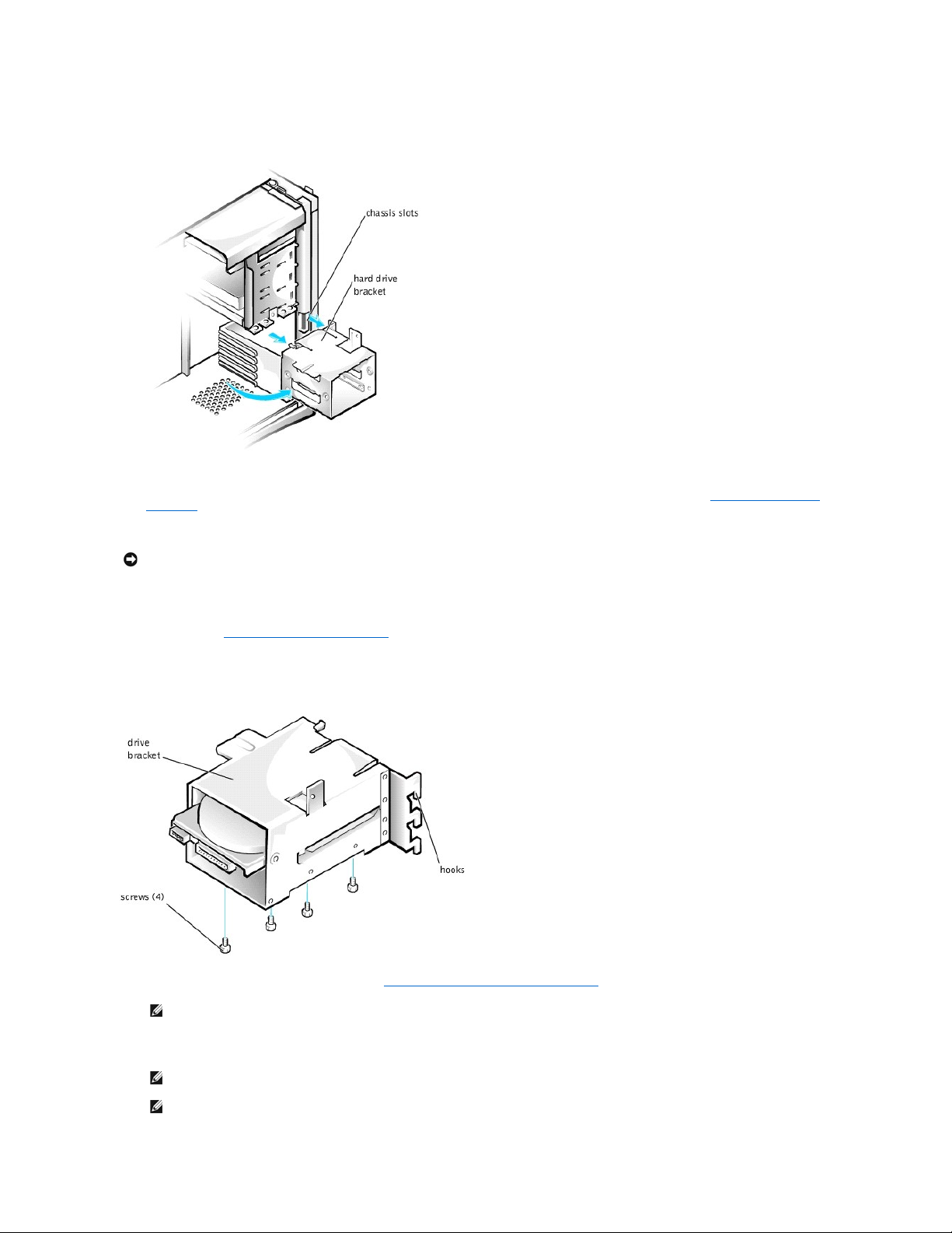
and lift it up off the bracket hooks and away from the chassis.
Removing the Hard Drive Bracket From the Chassis
If a drive is already installed in the bracket, disconnect the DC power cable and interface cable from the back of the drive before removing the bracket
from the chassis. To remove the old drive from the bracket, remove the four screws that secure the drive in the bracket (see "Installing a Hard Drive in
the Bracket").
5. Unpack the drive and prepare it for installation.
See the documentation that accompanied the drive to verify that the drive is configured for your computer. Change any settings necessary for your
configuration.
6. Slide the drive into one of the bracket bays, oriented so the connectors on the back of the drive will face the interior of the chassis when the bracket is
reinstalled (see "Installing a Hard Drive in the Bracket").
7. Align the screw holes of the drive and bracket, and secure the drive in the bracket using the screws that came with the upgrade kit (see the following
figure).
Installing a Hard Drive in the Bracket
8. Reinstall the hard drive bracket in the chassis (see "Installing the Hard- Drive Bracket in the Chassis").
Insert the drive bracket into the chassis, sliding it in until the tabs snap into place. Rotate the drive door upward to the chassis until it snaps securely
into place.
NOTICE: Ground yourself by touching an unpainted metal surface on the back of the computer.
NOTE: Orient the drive in the bracket so that its bottom will face the left side of the chassis when the bracket is installed in the chassis.
NOTE: When you rotate the drive door back into place, ensure that the tabs on the drive door are inserted between the drive bracket and the
drive cage.
NOTE: Be sure to fold down the drive door handle so that the front panel can be replaced on the chassis.
Page 24
Installing the Hard-Drive Bracket in the Chassis
9. Connect the interface cable for the drive (see "Attaching Hard Drive Cables in the Chassis").
a. If you are installing an EIDE device, ensure that the IDE interface cable is properly connected to the EIDE connector on the system board. For
more information, see "EIDE Device Installation Guidelines."
b. If you are installing a SCSI device, ensure that the SCSI interface cable is properly connected to the interface connector on the SCSI controller
board. For more information, see "SCSI Device Installation Guidelines."
10. Connect a DC power cable to the power input connector on the back of the drive (see the following figure).
Attaching Hard Drive Cables in the Chassis
11. Ensure that all cables are firmly connected. Fold cables out of the way to provide airflow for the fan and cooling vents.
12. Ensure that the control panel cable is firmly connected to the system board.
The control panel contains the hard-drive activity indicator. To locate the control panel system board connector, see "System Board Components."
13. Replace the front panel.
14. Replace the computer cover, reconnect the computer and peripherals to their electrical outlets, and turn them on.
ALERT! Cover was previously removed.
NOTICE: To avoid possible damage, you must match the colored strip on the interface cable with pin 1 on both the drive and system board connectors.
NOTE: If enabled, the Chassis Intrusion option will cause the following message to be displayed at the next system start-up:
Page 25

15. Enter system setup, and update the drive settings.
After you update the system settings, exit system setup and reboot the computer.
16. Partition and logically format the drive before proceeding to the next step.
See the operating system's documentation for instructions.
17. Run the Dell Diagnostics to test the drive.
18. If the hard drive you installed is the primary drive, install the operating system on the drive.
See the operating system's documentation for instructions.
EIDE Device Installation Guidelines
Jumper Settings
All EIDE drives should be configured for the Cable Select jumper position, which assigns master and slave status to drives by their position on the interface
cable. When two EIDE drives are connected to a single EIDE interface cable and are configured for the Cable Select jumper position, the drive attached to the
last connector on the interface cable is the master, or boot device (drive 0), and the device attached to the middle connector on the interface cable is the slave
device (drive 1). Refer to the documentation in your drive upgrade kit for information on setting devices to the Cable Select jumper position.
General Guidelines
With the two EIDE interface connectors on the input/output (I/O) board, your system can support up to four EIDE drives:
l The primary EIDE connector, labeled "IDE PRI," should be cabled to EIDE hard drives
l The secondary EIDE connector, labeled "IDE SEC," should be cabled to EIDE CD, DVD, tape, SuperDisk, and Zip drives
To locate the EIDE interface connectors on the system board, see "System Board Components." Each EIDE interface connector on the I/O board supports the
following:
l Two channels, master and slave
l Logical block addressing (LBA)
l Programmed I/O (PIO) Mode 3 and Mode 4
l Ultra Advanced Technology Attachment (ATA)/100, ATA/66, or ATA/33
EIDE Cables
Ultra ATA/66 and ATA/100 hard drives require an 80-conductor cable to transfer data at full speed. The 80-conductor cable has a 40-pin connector like the
ATA/33 cable, but it has twice as many wires within the cable. If you use an ATA/33 cable with Ultra ATA/100 hard drives, the drives will operate properly, but
data will transfer at ATA/33 speeds.
SCSI Device Installation Guidelines
This section describes how to configure and install SCSI devices in your system. To install a SCSI device, you must have a SCSI controller card installed in your
system.
SCSI ID Numbers
Internal SCSI devices must have a unique SCSI ID number from 0 to 15.
When SCSI devices are shipped from Dell, the default SCSI ID numbers for the primary and secondary controllers are assigned as follows:
l SCSI controller: SCSI ID 7
l Boot SCSI hard drive: SCSI ID 0
l SCSI CD drive: SCSI ID 5
l SCSI tape or digital audio tape (DAT) drive: SCSI ID 6
SCSI devices installed by Dell are configured correctly during the manufacturing process. You do not need to set the SCSI ID for these SCSI devices.
If you attach additional optional SCSI devices, refer to the documentation for each device for information about setting the appropriate SCSI ID number.
Device Termination
NOTE: A SuperDisk drive is typically installed as the master device on the secondary EIDE system-board connector.
NOTICE: DellrecommendsthatyouuseonlyEIDEcablespurchasedfromDell.CablespurchasedelsewherearenotguaranteedtoworkwithDell™
systems.
NOTE: There is no requirement that SCSI ID numbers be assigned sequentially or that devices be attached to the cable in order by ID number.
NOTICE: Dell recommends that you use only SCSI cables purchased from Dell. Cables purchased elsewhere are not guaranteed to work with Dell
systems.
Page 26
SCSI logic requires that termination be enabled for the two devices at opposite ends of the SCSI chain and disabled for all devices in between.
Dell recommends that you use terminated cables and that you disable termination on all devices. See the documentation provided with any optional SCSI
device you purchase for information on disabling termination on the device.
General Guidelines
Follow these general guidelines when installing SCSI devices in your computer:
l Although you install SCSI devices essentially the same way as other devices, their configuration requirements are different. For details on configuring
your particular SCSI subsystem, refer to the documentation for your SCSI devices and/or your host adapter card.
l Configure the device for a SCSI ID number and disable termination, if necessary.
l If you are installing an external SCSI device, connect one end of the external SCSI cable to the bus connector on the back of the device. Attach the
other end of the external SCSI cable to the connector on the controller installed in the computer.
l After installing a SCSI hard drive, Primary Drive 0 and Primary Drive 1 should be set to None in system setup. If you have any EIDE devices on the
second EIDE channel, such as a CD or tape drive, Secondary Drive 0 and/or Secondary Drive 1 should be set to Auto. If you have any SCSI devices on
the second EIDE channel, Secondary Drive 0 and/or Secondary Drive 1 should be set to None.
l You may need to use programs other than those provided with the operating system to partition and format SCSI hard drives. Refer to the
documentation that came with your SCSI software drivers for information on installing the appropriate drivers and preparing your SCSI hard drive for
use.
SCSI Cables
Ultra2/Wide low-voltage differential (LVD) drives (typically hard drives) use a 68-pin cable. One end of this cable attaches to the SCSI controller card. The
remaining connectors on the cable attach to the various LVD drives.
Narrow SCSI drives (tape drives, CD drives, and some hard drives) use a 50-pin cable. One end of this cable attaches to the SCSI controller card. The
remaining connectors on the cable attach to the various Narrow SCSI devices.
AGP Card Brace
To access some components on the system board in the chassis, you may need to remove the accelerated graphics port (AGP) card brace.
1. Turn off the computer and peripherals, disconnect them from their electrical outlets, wait at least 5 seconds, and then remove the computer cover.
2. Lay the computer on its right side.
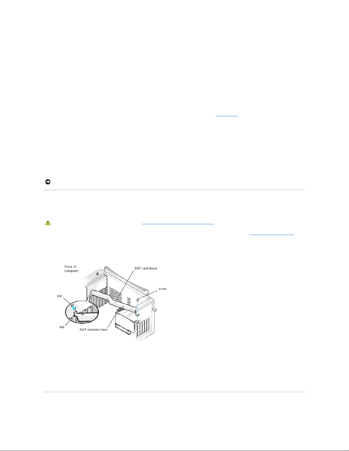
3. Remove the screw that secures the AGP card brace to the chassis (see the following figure).
Removing the AGP Card Brace
4. Rotate the brace up until it disengages from the card guide at the front of the chassis. Then lift the brace away from the chassis.
To replace the AGP card brace, perform the following steps:
1. Insert the tab on one end of the brace into the slot on the card guide at the front of the chassis (see the preceding figure).
2. Lower the brace, ensuring that the AGP retention lever on the bottom of the brace is aligned with the top of the AGP card.
3. Replace the screw that secures the brace to the chassis.
Expansion Cards
NOTICE: Dell recommends that you use only SCSI cables purchased from Dell. Cables purchased elsewhere are not guaranteed to work with Dell
systems.
CAUTION: Before you perform this procedure, see "Safety First— For You and Your Computer."
Page 27
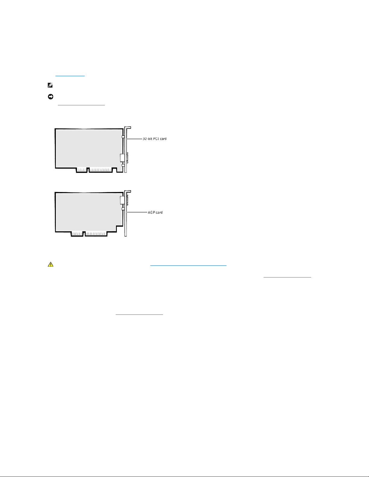
The system provides expansion slots for the following cards:
l Up to five 32-bit, 33-megahertz (MHz) Peripheral Component Interconnect (PCI) expansion cards.
l One 32-bit AGP card. The expansion slot supports AGP 4x or 2x modes operating at 1.5-volts (V).
See "Expansion Cards" for examples of these cards.
Expansion Cards
Installing an Expansion Card
1. Turn off the computer and peripherals, disconnect them from their electrical outlets, wait at least 5 seconds, and then remove the computer cover.
2. Lay the computer on its right side.
3. Prepare the expansion card for installation.
See the documentation that came with the expansion card for information on configuring the card, making internal connections, or otherwise customizing
it for your system.
4. If you are installing an AGP card, remove the AGP card brace.
5. Remove the screw that secures the expansion slot filler bracket to the chassis, and remove the bracket from the chassis (see the following figure).
Save the screw to use when installing the expansion card later in this procedure.
Removing the Filler Bracket
NOTE: To meet PC99 system requirements, your Dell computer uses only PCI expansion slots. Industry-Standard Architecture (ISA) expansion cards are
not supported. This is an industry standard for ease-of-use.
NOTICE: Before disconnecting a peripheral device from the computer, wait 10 to 20 seconds after disconnecting the computer from its electrical outlet.
Before removing a component from the system board, verify that the standby power light on the system board has turned off. To locate this light, see
"System Board Components."
CAUTION: Before you perform this procedure, see "Safety First— For You and Your Computer."
Page 28

6. Insert the expansion card into the expansion-card connector.
If the expansion card is full-length, insert the end of the card into the expansion card guide bracket as you lower the card toward its connector on the
system board. Insert the card firmly into the expansion-card connector on the system board (see the following figure).
Installing an Expansion Card
7. Secure the card's bracket to the chassis with the screw you removed in step 5.
8. Connect any cables that should be attached to the card.
See the documentation for the card for information about the card's cable connections.
9. If you removed the AGP brace, replace it.
10. Stand the computer upright.
11. Replace the computer cover, reconnect the computer and peripherals to their electrical outlets, and turn them on.
ALERT! Cover was previously removed.
12. If you installed a sound card, perform the following steps:
a. Enter system setup, select Integrated Devices and change the setting for Sound to Off.
b. Connect external audio devices to the sound card's connectors. Do not connect external audio devices to the microphone, line- out, or line-in
connectors on the system back panel (see "Back- Panel Connectors and Indicators").
CAUTION: Some network interface controllers (NICs) automatically start up the system when they are connected to a network. To guard against
electrical shock, be sure to unplug your computer from its electrical outlet before installing any expansion cards. Verify that the standby power
indicator on the system board is off. To locate this indicator, see "System Board Components."
NOTICE: An AGP Pro50 card may use multiple screws on its bracket. Install all screws on the expansion card's bracket.
NOTE: If enabled, the Chassis Intrusion option will cause the following message to be displayed at the next system start-up:
Page 29

13. If you installed an add-in NIC, perform the following steps:
a. Enter system setup, select Integrated Devices and change the setting for Network Interface Card to Off.
b. Connect the network cable to the add-in NIC's connectors. Do not connect the network cable to the integrated NIC connector on the system back
panel (see "Back-Panel Connectors and Indicators").
Removing an Expansion Card
1. Turn off the computer and peripherals, disconnect them from their electrical outlets, wait at least 5 seconds, and then remove the computer cover.
2. If you are removing an AGP card, remove the AGP card brace.
3. If necessary, disconnect any cables connected to the card.
4. Remove the screw that secures the expansion card bracket to the chassis.
Save the screw to use when installing the expansion card or filler bracket later in this procedure.
5. Grasp the card by its top corners, and ease it out of its connector.
6. If you are removing the card permanently, install a filler bracket in the empty card-slot opening, using the screw you removed in step 4.
If you need a filler bracket, contact Dell and order part number 81808.
7. If you removed the AGP brace, replace it.
8. Replace the computer cover, reconnect the computer and peripherals to their electrical outlets, and turn them on.
ALERT! Cover was previously removed.
9. If you removed a sound card, perform the following:
a. Enter system setup, select Integrated Devices and change the setting for Sound to On.
b. Connect external audio devices to the audio connectors on the system back panel (see "Back-Panel Connectors and Indicators").
10. If you installed an add-in NIC, perform the following:
a. Enter system setup, select Integrated Devices and change the setting for Network Interface Card to On.
b. Connect the network cable to the integrated NIC connector on the system back panel (see "Back-Panel Connectors and Indicators").
Microprocessor
Upgrading the Microprocessor
1. Turn off the computer and peripherals, disconnect them from their electrical outlets, wait at least 5 seconds, and then remove the computer cover.
2. Rotate the power supply away from the system board.
3. Remove the airflow shroud
a. Pull back the release tabs on top of the shroud and lift the shroud up until the anchor tabs disengage from the chassis frame (see "Removing the
Microprocessor Airflow Shroud From the Chassis").
b. Lift the airflow shroud out of the chassis.
Removing the Microprocessor Airflow Shroud From the Chassis
CAUTION: Before you perform this procedure, see "Safety First— For You and Your Computer."
NOTE: Installing filler brackets over empty card-slot openings is necessary to maintain Federal Communications Commission (FCC) certification of
the system. The brackets also keep dust and dirt out of your computer.
NOTE: If enabled, the Chassis Intrusion option will cause the following message to be displayed at the next system start-up:
NOTE: Dell recommends that only a technically knowledgeable person perform this procedure.
CAUTION: The processor can get very hot during system operation. Be sure that the processor has had sufficient time to cool before you touch it.
CAUTION: Before you perform this procedure, see "Safety First— For You and Your Computer."
Page 30

4. Remove the microprocessor heat sink:
a. For each of the metal clips that secure the heat sink to the microprocessor, press down on the clip's latch to release it from the heat-sink
retention base. Then lift the clip away from the heat sink (see "Removing the Microprocessor Heat Sink").
b. Lift the heat sink away from the microprocessor.
5. Discard the original microprocessor heat sink and securing clips.
Removing the Microprocessor Heat Sink
6. Remove the microprocessor from its connector.
NOTE: The bottom of the heat sink is covered with thermal grease that conducts heat from the processor to the heat sink. Some of this lubricant
will remain on the bottom of the heat sink when you remove it.
NOTICE: Do not discard the original microprocessor heat sink or securing clips unless you are installing a microprocessor upgrade kit from Dell. If
you are not installing a microprocessor upgrade kit from Dell, reuse the original heat sink and securing clips when replacing the microprocessor.
Page 31

Your microprocessor uses a zero insertion force (ZIF) socket with a lever-type handle that secures or releases the microprocessor.
To remove the microprocessor, pull the socket lever straight up until the microprocessor is released. Then remove the microprocessor from the socket
(see the following figure).
Removing the Microprocessor
7. Install the new microprocessor in the socket:
a. Ensure that the lever on the microprocessor socket is fully extended to the release position.
b. Align pin 1 of the new microprocessor with pin 1 of the socket.
c. Carefully set the microprocessor in the socket and press it down lightly to seat it.
d. Rotate the socket lever back toward the socket until it snaps into place, securing the microprocessor.
Replacing the Microprocessor
8. Install the microprocessor heat sink:
NOTICE: When you place the microprocessor in the socket, ensure that the microprocessor aligns properly with the socket. You must position the
microprocessor correctly in the socket to avoid damage.
NOTE: Pin 1 of the microprocessor is indicated by a small dot or a triangle in one corner of the microprocessor. Pin 1 of the socket is indicated by a
small triangle in one corner of the socket. See "Replacing the Microprocessor."
NOTICE: If you are not installing a microprocessor upgrade kit from Dell, reuse the original heat sink and securing clips when replacing the
microprocessor.
Page 32

a. Remove the film covering the thermal grease on the bottom of the heat sink.
b. Lower the heat sink to the microprocessor so that the heat sink fits in the heat sink retention base.
c. For each of the replacement metal clips that secure the heat sink to the microprocessor, fit the end of the clip that does not have the latch to the
heat sink retention base. Then press down on the clip's latch to secure the clip to the heat sink retention base (see "Removing the Microprocessor
Heat Sink").
9. Replace the airflow shroud.
10. Rotate the power supply back into position, making sure that the securing tab snaps into place.
11. Replace the computer cover, reconnect the computer and peripherals to their electrical outlets, and turn them on.
ALERT! Cover was previously removed.
12. Enter system setup, and confirm that the top line in the System Data area correctly identifies the new microprocessor. Also, confirm that the values
under the CPU Information menu are correct for the new microprocessor.
13. Exit system setup, and then run the Dell Diagnostics to verify that the new microprocessor is operating properly.
VRM
The voltage regulator module (VRM) senses the microprocessor's voltage requirements and ensures that the correct voltage is maintained.
Removing the VRM
1. Turn off the computer and peripherals, disconnect them from their electrical outlets, wait at least 5 seconds, and then remove the computer cover.
2. Rotate the power supply away from the system board.
3. Remove the VRM securing clip:
a. Press down on the two raised points of the clip's top surface to release it from the VRM connector.
b. Lift the clip away from the VRM (see the following figure).
Removing the VRM
4. Grasp the VRM by its top corners, and ease it out of its connector.
Replacing the VRM
1. Align the slot on the bottom of the new VRM with the ridge inside the connector.
2. Press the VRM straight into the connector.
3. Replace the VRM securing clip:
a. Lower the clip onto the VRM so that the top corners of the VRM go through the slots in the clip.
b. Press down on the two raised points of the clip's top surface to secure it to the VRM connector (see "Removing the VRM").
NOTE: If enabled, the Chassis Intrusion option will cause the following message to be displayed at the next system start-up:
CAUTION: Before you perform this procedure, see "Safety First— For You and Your Computer."
NOTICE: Before disconnecting a peripheral device from the computer, wait 10 to 20 seconds after disconnecting the computer from its electrical outlet.
Before removing a component from the system board, verify that the standby power light on the system board has turned off. To locate this light, see
"System Board Components."
Page 33

4. Rotate the power supply back into position until the securing tab snaps into the release latch.
5. Replace the computer cover and restart the system.
System Battery
The 3.0-V CR2032 coin-cell battery installed on the system board provides power to retain the configuration, date, and time information when the system is
turned off. The system battery is designed to provide years of service without being replaced. However, you may need to replace the battery if configuration
or clock-related inconsistencies occur or if one of the following messages is displayed during the boot routine:
Time-of-day not set - please run SETUP program
or
Invalid configuration information -
please run SETUP program
or
Strike the F1 key to continue,
F2 to run the setup utility
1. If you have not already done so, make a copy of your system configuration information in system setup.
If the settings are lost while you are replacing the battery, you can refer to your copy of the system configuration information to restore the correct
settings.
2. Turn off the computer and peripherals, disconnect them from their electrical outlets, wait at least 5 seconds, and then remove the computer cover.
3. Remove the battery.
See "System Board Components" in "About Your Computer" to locate the battery on the system board.
Pry the battery out of its socket with your fingers or with a blunt, nonconductive object, such as a plastic screwdriver.
4. Install the new battery.
Orient the battery with the side labeled "+" facing up (see the following figure). Then insert the battery into the socket, and snap it into place.
Replacing the System Battery
5. Replace the computer cover, reconnect the computer and peripherals to their electrical outlets, and turn them on.
ALERT! Cover was previously removed.
6. Enter system setup and enter the current time and date. Then exit system setup and save the information.
7. Turn off your computer and disconnect it from its electrical outlet. Leave the computer off for at least 10 minutes.
8. Reconnect the computer to its electrical outlet and turn it on.
9. Enter system setup and check the date and time.
CAUTION: There is a danger of the new battery exploding if it is installed incorrectly. Replace the battery only with the same or equivalent type
recommended by the manufacturer. Discard used batteries according to the manufacturer's instructions.
CAUTION: Before you perform this procedure, see "Safety First— For You and Your Computer."
NOTICE: If you use a blunt, nonconductive object to pry the battery out of its socket, be careful not to touch the system board with the object. Be sure
that the object is inserted between the battery and the socket before you attempt to pry out the battery. Otherwise, you may damage the system
board.
NOTE: If enabled, the Chassis Intrusion option will cause the following message to be displayed at the next system start-up:
Page 34

10. If the time and date are still incorrect, see "Getting Help" for instructions on obtaining technical assistance.
Back to Contents Page
Page 35

Back to Contents Page
Technical Specifications
Dell™OptiPlex™GX400SystemUser'sGuide
TechnicalSpecifications
Processor
Microprocessor type
Intel®Pentium®4 microprocessor. Design provides for future Dell-supported upgrades. A slower compatibility
speed can be set through system setup.
Internal cache
8-kilobyte (KB) first-level
L2 cache memory
256-KB pipelined-burst, eight-way set-associative, write-back static random-access memory (SRAM)
Math coprocessor
internal to microprocessor
Memory
Architecture
Rambus dynamic random access memory (RDRAM)
Rambus in-line memory module
(RIMM) sockets
four
RIMM capacities
64-, 128-, 256-, and 512-megabyte (MB) RDRAM
Standard RAM
128 MB minimum
Maximum RAM
2 gigabyte (GB)
Basic input/output system (BIOS)
address
F8000h
System Information
Chip set
Intel 850 Peripheral Component Interconnect (PCI)/accelerated graphics port (AGP)
Data bus width
64 bits
Address bus width
32 bits
Direct memory access (DMA)
channels
eight
Interrupt levels
15
BIOS chip
4 megabits (Mb)
System bus speed
100 megahertz (MHz) clock, 400 MHz data rate
Video
Video type
AGP 4X or PCI graphics card (see manufacturer's specifications)
Bus speed
66 MHz
AGP expansion-card connectors
one
AGP expansion-card connector size
172 pins
AGP expansion-card connector
data width (maximum)
32 bits
AGP bus protocols
4x/2x modes at 1.5 volts (V) (3.3 volt AGP cards are not supported.)
Audio
Audio type
Soundblaster emulation
Audio controller
Analog Devices AD1885 AC97 Codec
Stereo conversion
16 bits (analog-to-digital and digital-to-analog)
Interfaces:
Internal
PCI bus/AC97
CDROM
Telephony applications programming interface (TAPI)
External
line-in jack;
microphone jack;
line-out jack
Expansion Bus
Bus types
PCI
Bus speed
PCI: 33 MHz
PCI expansion-card connectors
five
PCI expansion-card connector size
120 pins
PCI expansion-card connector
data width (maximum)
32 bits
Drives
Externally accessible bays
three 5.25-inch bays for diskette, tape, or CD drives; one 3.5-inch bay for a diskette drive
Internally accessible bays
two 3.5-inch bays for two 1-inch high hard drives or one 1-inch high hard drive and one 1.6-inch-high hard drive
Ports
Externally accessible:
Page 36

Serial (DTE)
two 9-pin connectors; 16550-compatible
Parallel
one 25-hole connector (bidirectional)
Video
one 15-hole connector (on video card)
Network interface controller
(NIC)
RJ45 connector
Personal System/2 (PS/2)-style
keyboard
6-pin mini-Deutsche Industrie Norm (DIN)
PS/2-compatible mouse
6-pin mini-DIN
Universal Serial Bus (USB)
four USB-compliant connectors
Audio
one microphone jack;
one line-in jack;
one line-out jack
Internally accessible:
Primary enhanced
integrated drive
electronics (EIDE)
hard drive
40-pin connector on PCI local bus
Secondary EIDE hard drive
40-pin connector
Diskette drive
34-pin connector
CD drive audio interface
4-pin connector
Fan
3-pin connector
Telephony (TAPI)
4-pin connector
Key Combinations
<Ctrl><Alt><Del>
restarts (reboots) the system
<F2>
starts system setup during power-on self-test (POST) only
<Ctrl><Alt><\>
toggles microprocessor speeds on 101-key keyboard (in MS-DOS®real mode only)
<Ctrl><Alt><#>
toggles microprocessor speeds on 102-key keyboard (in MS-DOS real mode only)
<Ctrl><Enter>
disables the system password at start-up
Controls and Indicators
Reset control
push button
Power control
push button
Power indicators
green light blinking green in sleep state; dual-color light on front panel—green for power, yellow for diagnostics
Hard-drive access indicator
green light
Link integrity and speed indicator
(on integrated NIC connector)
green light for 10-Mb operation; orange light for 100-Mb operation
Activity indicator (on NIC connector)
yellow light
Power
DC power supply:
Wattage
250 Watts (W)
Heat dissipation
913 British thermal units (BTU) (fully loaded system without monitor)
Voltage
90 to 135 V at 60 hertz (Hz); 180 to 265 V at 50 Hz
Backup battery
3-V CR2032 coin cell
Physical
Height
44.5 centimeters (cm) (17.5 inches)
Width
20.6 cm (8.1 inches)
Depth
43.7 cm (17.2 inches)
Weight
15 kilograms (kg) (33.0 pounds [lb]) or more, depending on options installed)
Environmental
Temperature:
Operating
10°to35°C(50°to95°F)
Storage
–40°to65°C(–40°to149°F)
Relative humidity
20% to 80% (noncondensing)
Maximum vibration:
Operating
0.25 gravities (G) at 3 to 200 Hz at 0.5 octave/minute (min)
Storage
0.5 G at 3 to 200 Hz at 1 octave/min
Maximum shock:
Operating
bottom half-sine pulse with a change in velocity of 20 inches/second (sec) (50.8 cm/sec)
Storage
27-G faired square wave with a velocity change of 200 inches/sec (508 cm/sec)
Altitude:
Operating
–16 to 3048 meters (m) (–50 to 10,000 feet [ft])
Storage
–16 to 10,600 m (–50 to 35,000 ft)
Page 37

Back to Contents Page
Page 38

Back to Contents Page
Solving Problems
Dell™OptiPlex™GX400SystemUser'sGuide
Before You Begin
Dell Diagnostics
Messages and Codes
Software Problems
Before You Begin
This section describes system and software problems, offers corrective actions, describes the Dell Diagnostics utility, and provides system messages and
codes. Before you call Dell for technical assistance, complete the following tasks to help you resolve computer problems:
l Read "About Your Computer" and "Safety First—For You and Your Computer."
l Take the problem-solving action listed in the following table for the component or equipment that is not working properly.
Power Problems
The power indicator on the front panel communicates codes that can help you determine whether there is a problem with your computer. The following table
lists the codes for the power indicator. For more information, see "Diagnostic Indicators."
Basic Checks:
l Test the electrical outlet: ensure that the electrical outlet is working by testing it with a different device such as a lamp.
l Connect the computer power cable directly to an electrical outlet to ensure that the computer turns on. Do not connect it to a power protection device,
uninterruptible power supply (UPS), power strip, or extension cord.
l Ensure that all power cables are firmly connected, verifying that each power cable is adequately connected at the computer device and to the electrical
outlet.
l Check for interference: electrical appliances on the same circuit or operating in close proximity to the computer can cause interference.
Solving Problems
Problem
Action
Power indicator does not light
See "Power Problems"
Monitor power indicator does not light
See "Monitor Problems"
No sound
See "Sound and Speaker Problems"
Printer not working
See "Printer Problems"
Serial or other parallel devices not working
See "Serial or Parallel Device Problems"
Mouse not working
See "Mouse Problems"
Keyboard not working
See "Keyboard Problems"
Diskette drive or hard drive: indicators not lit, scraping or unusual noises, no noise
See "Diskette Drive Problems" or "Hard Drive Problems"
System battery not working
See "Battery Problems"
Expansion card errors or malfunction
See "Expansion-Card Problems"
A program locks up
See "Recover From a Program That Is Not Responding"
Computer locks up
See "Restart a Computer That Is Not Responding"
Computer gets wet
See "Repairing a Wet Computer"
Computer is dropped or damaged
See "Repairing a Dropped or Damaged Computer"
Hardware devices conflict
See "Hardware Conflicts"
System memory amount is not correct
See "System Memory Problems"
System board malfunctions
See "System Board Problems"
System board is damaged
See "Resetting a Damaged System Board"
An error message
See "Messages and Codes"
A series of beeps on system startup
See "Messages and Codes"
Power Indicator Codes
Power Indicator Code
Cause
Solid green
Power is on, and the computer is operating normally.
Blinking green
The computer is in the suspended state (Microsoft®Windows®2000 only).
Solid yellow
The Dell Diagnostics is running a test, or a device on the system board may be faulty or incorrectly installed.
Blinking yellow
There is a system board or power supply failure.
Page 39

l Swap the power cables between the computer and the monitor to see whether the problem symptoms change.
If the problem still exists after you complete the basic checks, fill out the Diagnostics Checklist as you perform the following steps:
1. Turn off the computer and peripherals, and disconnect them from their electrical outlets.
2. Wait approximately 30 seconds, and reconnect the computer and peripherals to their electrical outlets.
3. Turn on the computer.
Does the power indicator on the front of the computer light up?
Yes. The problem is resolved.
No. The computer may be defective. Contact Dell for technical assistance.
Monitor Problems
The power indicator on the monitor communicates codes that can help you determine whether there is a problem. The following table lists the codes for the
monitor power indicator. For more information, see the documentation that came with your monitor.
Basic Checks:
l Run the monitor self-test as instructed in the monitor user's guide.
l Connect the monitor power cable directly to an electrical outlet to ensure that the monitor turns on. Do not connect it to a power protection device, UPS,
power strip, or extension cord.
l Ensure that the monitor power cable is firmly connected, verifying that the power cable is adequately connected at the monitor and to the electrical
outlet.
l Swap the power cables between the computer and the monitor to see whether the problem symptoms change.
l If the monitor display is blank, the computer may be in suspended, or hibernate, state. Push and release the power button, move the mouse, or press a
key on the keyboard to bring the computer out of the suspended state.
l Disconnect the monitor interface cable from the computer and check the cable connector for bent or broken pins. Check for damaged or frayed cables.
l If the monitor interface cable is not damaged, ensure that it is firmly connected to the computer.
l Adjust brightness and contrast settings on the monitor.
If the problem still exists after you complete the basic checks, fill out the Diagnostics Checklist as you perform the following steps:
1. Turn off the computer, wait at least 30 seconds, and then turn the computer back on.
2. Allow 1 minute for the computer to initialize its components, and then adjust the monitor's brightness and contrast controls.
Is the monitor readable?
Yes. The problem is resolved.
No. Go to step 3.
3. Turn off nearby fans, lights, lamps, or other electrical devices.
Is the monitor readable?
Yes. One or more of those devices was causing interference. The problem is resolved.
No. Go to the next question.
Do you have another monitor that is working properly?
Yes. Go to step 4.
No. Contact Dell for technical assistance.
4. Turn off the computer and the monitor, wait at least 30 seconds, and disconnect the monitor. Connect a different monitor to the computer and then
turn them on.
5. Allow 1 minute for the computer to initialize its components, and then adjust the monitor's brightness and contrast controls.
Is the monitor readable?
Yes. The original monitor is defective. The problem is resolved.
No. Contact Dell for technical assistance.
Video Problems
MonitorIndicatorCodes
Monitor Indicator Code
Cause
Solid green
Power is on, and the monitor is receiving video input from the computer. The system is operating normally.
Solid yellow
Power is on, but the monitor is not receiving video input from the computer.
Page 40

Basic Checks:
l Run the monitor self-test as instructed in the monitor user's guide.
l Check the monitor power indicator.
l Listen for system beep codes that may indicate a display problem.
l Connect the monitor power cable directly to an electrical outlet to verify that the monitor turns on. Do not connect it to a power protection device, UPS,
power strip, or extension cord.
l If the monitor display is blank, the computer may be in suspended, or hibernate, state. Push and release the power button, move the mouse, or press a
key on the keyboard to bring the computer out of the suspended state.
l Disconnect the monitor interface cable from the computer and check the cable connector for bent or broken pins. Check for damaged or frayed cables.
l If the monitor interface cable is not damaged, ensure that it is firmly connected to the computer.
l Adjust brightness and contrast settings on the monitor.
l Check for interference:
¡ Electrical appliances on the same circuit or operating in close proximity to the computer can cause interference.
¡ Audio equipment and certain types of lamps operating in immediate proximity to the computer can cause interference.
l Restart the computer.
l Enter system setup and ensure that Primary Video Controller under the Integrated Devices option is set correctly. An advanced graphics port (AGP) or
peripheral component interconnect (PCI) expansion card will operate with Primary Video Controller set to either Auto or the default setting AGP.
If the problem still exists after you complete the basic checks, fill out the Diagnostics Checklist as you perform the following steps:
1. Perform the procedure in "Monitor Problems."
Is the computer working properly?
Yes. The problem is resolved.
No. Go to the next question.
Do you have another computer that is working properly?
Yes. Go to step 2.
No. Go to step 6.
2. Turn off the original computer and monitor, wait at least 30 seconds, and disconnect the monitor.
3. Turn off your other computer, wait at least 30 seconds, and disconnect its monitor. Connect the monitor from the original computer, and then turn them
on.
4. Allow 1 minute for the computer to initialize its components, and then adjust the monitor's brightness and contrast controls.
Is the monitor readable?
Yes. The monitor is working properly. There may be a problem with the video card in the original computer. Go to step 5.
No. The monitor may be defective. See "Monitor Problems."
5. Turn off the computer and monitor, wait at least 30 seconds, and disconnect the monitor. Connect the monitor back to the original computer, and then
turn them on.
6. Turn off nearby fans, lights, lamps, or other electrical devices.
Is the monitor readable?
Yes. One or more of those devices was causing interference. The problem is resolved.
No. Go to step 7.
7. Run the VESA/VGA Interface tests in the Dell Diagnostics.
Did any of the tests fail?
Yes. The video controller on the system board may be defective. Contact Dell for technical assistance.
No. Contact Dell for technical assistance.
Sound and Speaker Problems
Basic Checks:
l If using external speakers:
¡ Ensure that external audio devices are connected to the microphone, line-out/speaker, or line-in connectors on the system back panel.
NOTE: If your computer has both an AGP and a PCI expansion card installed, set Primary Video Controller to AGP to use the AGP expansion
card. Set Primary Video Controller to Auto to use the PCI expansion card.
Page 41

¡ Ensure that the speaker cable is firmly connected to the computer.
¡ Test the electrical outlet. Verify that the speakers are connected to a working electrical outlet.
¡ Ensure that the speakers are turned on.
l If using a sound card, ensure that external audio devices are connected to the sound card's connectors and not to the microphone, line- out/speaker, or
line-in connectors on the system back panel (see "Back- Panel Connectors and Indicators").
l Ensure that audio is not muted in the operating system (OS) settings. See the OS documentation for more information.
l Adjust the volume control on the speakers, if it is provided.
l Adjust the volume control in the audio software. For more information, see the documentation for either your OS or your audio software.
l If you are trying to listen to an audio CD, try different CDs.
l Reinstall the audio driver for your operating system.
l Check for interference: electrical appliances on the same circuit or operating in close proximity to the computer can cause interference.
If the problem still exists after you complete the basic checks, fill out the Diagnostics Checklist as you perform the following steps:
1. Turn off nearby fans, lights, lamps, or other electrical devices.
Are the external speakers functioning properly?
Yes. One or more of those electrical devices was causing interference. The problem is resolved.
No. Go to step 2.
2. Enter system setup and make sure that Sound under the Integrated Devices option is set to On. Then exit system setup properly to save the
information, and reboot the system.
Is the device working properly?
Yes. The problem is resolved.
No. Go to step 3.
3. Run the Misc. PCI Devices tests in the Dell Diagnostics.
Did the tests complete successfully?
Yes. The controller is working properly. Go to the next question.
Do you have a set of headphones?
Yes. Go to step 4.
No. Contact Dell for technical assistance.
4. Connect the headphones to the line-out/speaker jack.
Can you hear sound through the headphones?
Yes. The speakers are defective. The problem is resolved.
No. Contact Dell for technical assistance.
Printer Problems
Basic Checks:
l Disconnect the cable from the computer and check the cable connector for bent or broken pins. Check for damaged or frayed cables.
l If the cable is not damaged, ensure that it is firmly connected to the computer.
l Test the electrical outlet. Verify that the printer is connected to a working electrical outlet.
l Ensure that the printer is turned on.
l Check for interference: electrical appliances on the same circuit or operating in close proximity to the computer can cause interference.
If the problem still exists after you complete the basic checks, fill out the Diagnostics Checklist as you perform the following steps:
1. Perform the procedure in "Serial or Parallel Device Problems."
Is the device working properly?
Yes. The problem is resolved.
No. Go to step 2.
2. Run the printer's self-test.
Does the self-test complete successfully?
Yes. Go to step 3.
Page 42

No. The printer is probably defective. If you bought the printer from Dell, contact Dell for technical assistance. If you did not, take it to an authorized
service center for repair.
3. Try to print again.
Does the print operation complete successfully?
Yes. The problem is resolved.
No. Contact Dell for technical assistance.
Serial or Parallel Device Problems
If a system error message indicates a port problem or if equipment connected to a port seems to perform incorrectly or not at all, the source of the problem
can be any of the following:
l A faulty connection between the input/output (I/O) port and the device
l Incorrect settings for system setup options
l Incorrect settings in the operating system's configuration files
l A faulty cable between the I/O port and the device
l A faulty device
l Faulty I/O port logic on the system board
l Conflicting COM port settings
l Lack of drivers
Basic Checks:
l Disconnect the cable from the computer and check the cable connector for bent or broken pins. Check for damaged or frayed cables.
l If the cable is not damaged, ensure that it is firmly connected to the computer.
l Test the electrical outlet. Verify that the device is connected to a working electrical outlet.
l Verify that the device is turned on.
l Check for interference: electrical appliances on the same circuit or operating in close proximity to the computer can cause interference.
If the problem still exists after you complete the basic checks, fill out the Diagnostics Checklist as you perform the following steps:
1. Enter system setup and check the Integrated Devices option settings. Then exit system setup properly to save the information, and reboot the
system.
For a serial device, check the Serial Port options; for a parallel device, check the Parallel Port options. See the device's documentation for additional
information on port settings and configuration requirements.
Is the device working properly?
Yes. The problem is resolved.
No. Go to step 2.
2. Run the Serial Ports device group and/or the Parallel Ports device group in the Dell Diagnostics.
These device groups check the basic functions of the system board's I/O port logic. If a printer is connected to the parallel port, the Parallel Ports device
group tests the communication link between the system board's I/O port logic and the printer.
Do the tests complete successfully?
Yes. Go to step 3.
No. Contact Dell for technical assistance.
3. If the problem is confined to a particular application program, see the application program's documentation for specific port configuration requirements.
Is the device working properly?
Yes. The problem is resolved.
No. Go to step 4.
4. Turn off the computer and the device, swap the device's cable with a known working cable, and then turn on the computer and the device.
Is the device working properly?
Yes. You need a new device cable. Contact Dell for technical assistance.
No. Go to step 5.
5. Turn off the computer and the device, swap the device with a comparable working device, and then turn on the computer and the device.
NOTE: If you are having a problem with a printer, see "Printer Problems."
Page 43

Is the device working properly?
Yes. You need a new device. Contact Dell for technical assistance.
No. Contact Dell for technical assistance.
Mouse Problems
Basic Checks:
l Disconnect the cable from the computer and check the cable connector for bent or broken pins. Check for damaged or frayed cables.
l Ensure that the cable is firmly connected to the computer.
l If you are using a USB mouse, ensure that you connect to one of the Port 1 USB connectors on the system back panel (see "Back-Panel Connectors and
Indicators").
l Reinstall the mouse driver for your operating system.
l Restart the computer.
If the problem still exists after you complete the basic checks, fill out the Diagnostics Checklist as you perform the following steps:
1. Turn off the computer, wait at least 30 seconds, and disconnect the mouse. Reconnect the mouse to the computer, and then turn the computer on.
Is the device working properly?
Yes. The problem is resolved.
No. Go to step 2.
2. If you are using a Personal System/2 (PS/2) mouse, enter system setup and make sure that Mouse Port under the Integrated Devices option is set to
On. Then exit system setup properly to save the information, and reboot the system.
Is the device working properly?
Yes. The problem is resolved.
No. Go to step 3.
3. If you are using a PS/2 mouse, run the Mouse test in the Pointing Devices device group in the Dell Diagnostics.
Did the tests complete successfully?
Yes. Go to the next question.
No. Contact Dell for technical assistance.
Do you have another computer that is working properly?
Yes. Go to step 4.
No. Go to the next question.
Do you have another mouse that is working properly?
Yes. Turn off the computer, wait at least 30 seconds, and disconnect the mouse. Then go to step 6.
No. Contact Dell for technical assistance.
4. Turn off the original computer, wait at least 30 seconds, and disconnect the mouse.
5. Turn off your other computer, wait at least 30 seconds, and disconnect its mouse. Connect the mouse from the original computer, and then turn the
computer on.
Is the mouse working properly?
Yes. There is a problem with the original computer. Contact Dell for technical assistance.
No. The mouse may be defective. Contact Dell for technical assistance.
6. Connect a different mouse to the computer, and then turn the computer on.
Is the mouse working properly?
Yes. The original mouse is defective. The problem is resolved.
No. Contact Dell for technical assistance.
Keyboard Problems
Basic Checks:
l Disconnect the cable from the computer and check the cable connector for bent or broken pins. Check for damaged or frayed cables.
l Ensure that the cable is firmly connected to the computer.
Page 44

l If you are using a USB keyboard, ensure that you connect to one of the Port 1 USB connectors on the system back panel (see "Back-Panel Connectors
and Indicators").
l If you are using a PS/2 keyboard that can be configured with various switch settings, ensure that the switch is set to PS/2, Enhanced XT/AT, or PC/AT.
The switch settings are usually on the bottom of the keyboard, sometimes behind a panel. Refer to the documentation that came with the keyboard for
more information.
l Check for interference. Keyboard extension cables can cause problems.
l Restart the computer.
If the problem still exists after you complete the basic checks, fill out the Diagnostics Checklist as you perform the following steps:
1. Turn off the computer, and then disconnect the keyboard cable and check it for bent or broken pins.
Do you see bent pins?
Yes. If they can be straightened, straighten them and go to step 2. If they cannot be straightened or are broken, you must replace the keyboard.
No. Go to step 2.
2. Reconnect the keyboard to the computer.
Make sure the keyboard cable is firmly connected to computer.
3. Turn on the computer.
4. If you are using a keyboard that can be configured with various switch settings, make sure the switch is set to PS/2, Enhanced XT/AT, or PC/AT.
The switch settings are usually on the bottom of the keyboard, sometimes behind a panel. Refer to the documentation that came with the keyboard for
more information.
5. Turn off the computer, wait 30 seconds, and turn it on again.
During the boot routine, do the Num Lock, Caps Lock, and Scroll Lock lights on the keyboard blink momentarily?
Yes. Go to step 6
No. Go to step 7.
6. Use the keyboard to type some characters.
Do the characters appear on the screen?
Yes. The problem is resolved.
No. Contact Dell for technical assistance.
7. Run the PC-AT Compatible Keyboards tests in the Dell Diagnostics.
Did any of the diagnostics tests fail?
Yes. The original keyboard may be defective. Go to step 8.
No. Go to the next question.
Do you have another computer that is working properly?
Yes. Go to step 8.
No. Go to the next question.
Do you have another keyboard that is working properly?
Yes. Turn off the computer, wait at least 30 seconds, and disconnect the keyboard. Go to step 9.
No. Contact Dell for technical assistance.
8. Turn off the original computer, wait at least 30 seconds, and disconnect the keyboard.
9. Turn off your other computer, wait at least 30 seconds, and disconnect its keyboard. Connect the keyboard from the original computer, and then turn
the computer on.
Is the keyboard working properly?
Yes. The original keyboard is defective. The problem is resolved.
No. Contact Dell for technical assistance.
Diskette Drive Problems
During the power-on self-test (POST), the computer checks the diskette drive, comparing its characteristics with the system configuration information. The
diskette-drive access light blinks as the computer performs this check.
Basic Checks:
l If you hear an unfamiliar scraping or grinding sound when a drive is accessed, there could be a hardware malfunction. Contact Dell for technical
Page 45

assistance.
l When you turn on the computer, you can hear drive activity during the boot routine. If your computer does not boot, contact Dell for technical
assistance.
l If you are trying to copy data to the diskette, ensure that it is not write- protected.
l Try a different diskette in the drive. If the new diskette works, the original one may be defective.
l Test the diskette drive access indicator by using one of the following methods:
¡ Using MS-DOS®, insert a diskette into the drive, type dir a: at the prompt, and press <Enter>.
¡ Using Microsoft Windows or Windows NT®, insert a diskette into the drive, open My Computer from the desktop, and double-click the diskette
drive icon.
l Check the settings in system setup.
l Clean the drive using a commercially available cleaning kit.
If the problem still exists after you complete the basic checks, fill out the Diagnostics Checklist as you perform the following steps.
1. Run the Diskette device group in the Dell Diagnostics.
Did any of the tests fail?
Yes. Contact Dell for technical assistance.
No. Go to step 2.
2. Turn off the computer and peripherals, disconnect them from their electrical outlets, wait at least 5 seconds, and then remove the computer cover.
3. Remove and reinstall the diskette drive.
4. Replace the computer cover, reconnect the computer and peripherals to their electrical outlets, and turn them on.
Does the diskette-drive access light blink during the boot routine?
Yes. Go to the next question.
No. Contact Dell for technical assistance.
Does the computer display a drive error message?
Yes. See "System Messages" for an explanation of the message, and then go to step 5.
No. The problem is resolved.
5. Insert a bootable diskette into the diskette drive and reboot the computer.
Does the drive boot the operating system?
Yes. The problem is probably resolved. If you continue to experience trouble, contact Dell for technical assistance.
No. Contact Dell for technical assistance.
Hard Drive Problems
Basic Checks:
l If you hear an unfamiliar scraping or grinding sound when a drive is accessed, there could be a hardware malfunction. Contact Dell for technical
assistance.
l When you turn on the computer, you can hear drive activity during the boot routine. If your computer does not boot, contact Dell for technical
assistance.
l Test the hard drive by using one of the following methods:
¡ For Windows XP and Windows 2000, run the chkdsk utility by clicking the Start button, selecting Run, and then typing cmd in the dialog box. At the
C: prompt, type chkdsk and press <Enter>.
This utility creates and displays a status report, and lists and corrects errors on the disk.
¡ For Windows NT, run the error-checking utility by double-clicking My Computer and selecting the hard drive that you want to check. Click the right
mouse button, select Properties, then click Tools, and select Check Now in the Error Checking section.
¡ For Windows 98 SE and Windows 98, run the ScanDisk utility by clicking the Start button, pointing to Run, typing scandskw in the dialog box,
selecting the type of test to run, and then clicking Start.
¡ For MS-DOS, type scandisk x: at an MS-DOS prompt, where x is the hard drive letter, and press <Enter>.
If the problem still exists after you complete the basic checks, fill out the Diagnostic Checklist as you perform the following steps:
NOTICE: Do not attempt to clean drive heads with a swab. You may accidentally misalign the heads, rendering the drive inoperable.
CAUTION: Before you perform this procedure, see "Safety First— For You and Your Computer."
Page 46

1. Enter system setup and make sure the problem drive is configured correctly. Make any necessary changes, and reboot the system.
Is the drive operating properly?
Yes. The problem is resolved.
No. Go to step 2.
2. Test the hard drive by using one of the following methods:
l Test the hard drive by using one of the following methods:
¡ For Windows XP and Windows 2000, run the chkdsk utility by clicking the Start button, selecting Run, and then typing cmd in the dialog box. At the
C: prompt, type chkdsk and press <Enter>.
This utility creates and displays a status report, and lists and corrects errors on the disk.
¡ For Windows NT, run the error-checking utility by double-clicking My Computer and selecting the hard drive that you want to check. Click the right
mouse button, select Properties, then click Tools, and select Check Now in the Error Checking section.
¡ For Windows 98 SE and Windows 98, run the ScanDisk utility by clicking the Start button, pointing to Run, typing scandskw in the dialog box,
selecting the type of test to run, and then clicking Start.
¡ For MS-DOS, type scandisk x: at an MS-DOS prompt, where x is the hard drive letter, and press <Enter>.
Is the drive operating properly?
Yes. The problem is resolved.
No. Go to step 3.
3. Run the appropriate test group in the Dell Diagnostics:
l For an integrated drive electronics (IDE) hard drive, run the IDE Devices device group.
l For a small computer system interface (SCSI) hard drive, run the SCSI Devices device group.
Did any of the diagnostics tests fail?
Yes. Go to the next question.
No. Go to step 4.
Did any of the diagnostics tests indicate a faulty drive?
Yes. The hard drive may be faulty. Contact Dell for technical assistance.
No. Go to the next question.
Did any of the diagnostics tests indicate a faulty drive controller?
Yes. The system board may be faulty. Contact Dell for technical assistance.
No. Go to step 4.
4. Turn off the computer and peripherals, disconnect them from their electrical outlets, wait at least 5 seconds, and then remove the computer cover.
5. Make sure the DC power cables from the power supply are firmly connected to the connectors on each drive. Also verify that the interface cable for each
drive is firmly connected to the drive and to the system board.
6. Make sure the control panel cable is firmly connected to the system board. The control panel contains the hard drive activity indicator. To locate the
control panel system board connector, see "System Board Components."
7. Replace the computer cover, reconnect the computer and peripherals to their electrical outlets, and turn them on.
Does the hard drive activity light blink during the boot routine?
Yes. Go to the next question.
No. The system board may be faulty. Contact Dell for technical assistance.
Does the computer display a drive error message?
Yes. See "System Messages" for an explanation of the message. If you cannot correct the problem by performing the action described in the table, then
contact Dell for technical assistance.
No. Go to the next question.
Is this the primary hard drive that contains the operating system?
Yes. Go to the next question.
No. Contact Dell for technical assistance.
CAUTION: Before you perform this procedure, see "Safety First— For You and Your Computer."
Page 47

Does the drive boot the operating system?
Yes. Go to the next question.
No. Files in the operating system may be corrupt. See your operating system documentation.
Is the drive operating properly?
Yes. The problem is resolved.
No. Contact Dell for technical assistance.
Battery Problems
If an error message indicates a problem with the battery or if configuration information is lost from system setup when the computer is turned off, the battery
may be defective.
1. Turn off the computer and peripherals, disconnect them from their electrical outlets, wait at least 5 seconds, and then remove the computer cover.
2. Reseat the battery in its socket with the side labeled "+" facing up.
3. Replace the computer cover, reconnect the computer and peripherals to their electrical outlets, and turn them on.
4. Enter system setup and reenter the current time and date. Then exit system setup properly to save the information.
5. Turn off your computer and disconnect it from its electrical outlet. Leave the computer off for at least 10 minutes.
6. Reconnect the computer to its electrical outlet and turn it on.
7. Enter system setup, and check the date and time.
Are the date and time correct?
Yes. The problem is resolved.
No. The battery may be defective. Go to step 8.
8. Replace the battery.
Is the battery working properly?
Yes. The problem is resolved.
No. You may have a faulty system board. Contact Dell for technical assistance.
Expansion-Card Problems
If an error message indicates an expansion-card problem or if an expansion card seems to perform incorrectly or not at all, the problem could be a faulty
connection, a conflict with software or other hardware, or a faulty expansion card.
Fill out the Diagnostics Checklist as you perform the following steps.
1. Run the diagnostics provided by the manufacturers of all expansion cards installed in your computer.
2. Turn off the computer and peripherals, disconnect them from their electrical outlets, wait at least 5 seconds, and then remove the computer cover.
3. Remove the AGP card brace.
4. Make sure each expansion card is firmly seated in its connector. If any expansion cards are loose, reseat them.
5. Make sure all cables are firmly connected to their corresponding connectors on the expansion cards. If any cables appear loose, reconnect them.
For instructions on which cables should be attached to specific connectors on an expansion card, see the expansion card's documentation.
6. Replace the AGP card brace.
7. Replace the computer cover, reconnect the computer and peripherals to their electrical outlets, and turn them on.
Is the system working properly?
Yes. The problem is resolved.
No. You may have a faulty expansion card. Go to step 8.
8. Turn off the computer and peripherals, disconnect them from their electrical outlets, wait at least 5 seconds, and then remove the computer cover.
CAUTION: There is a danger of a new battery exploding if it is incorrectly installed. Replace the battery only with the same or equivalent type
recommended by the manufacturer. Discard used batteries according to the manufacturer's instructions.
CAUTION: Before you perform this procedure, see "Safety First— For You and Your Computer."
CAUTION: Before you perform this procedure, see "Safety First— For You and Your Computer."
NOTE: The manufacturers of many expansion cards, such as video, network interface, and sound cards, provide diagnostics programs. If you do
not have any diagnostics for your cards, go to step 2.
Page 48

9. Remove all expansion cards except the video card.
10. Replace the computer cover, reconnect the computer and peripherals to their electrical outlets, and turn them on.
11. Run the RAM test group in the Dell Diagnostics.
Did any of the diagnostics tests fail?
Yes. Contact Dell for technical assistance.
No. Go to step 12.
12. Turn off the computer and peripherals, disconnect them from their electrical outlets, wait at least 5 seconds, and then remove the computer cover.
13. Reinstall one of the expansion cards that you removed previously, and repeat step 10 and step 11.
Did any of the diagnostics tests fail?
Yes. The expansion card you just reinstalled is faulty and needs to be replaced.
No. Repeat step 12 and step 13 with another expansion card. Go to step 13.
14. If you have replaced all the expansion cards and the problem is not resolved, contact Dell for technical assistance.
Recover From a Program That Is Not Responding
1. Press <Ctrl><Alt><Delete>.
Did the Close Program window appear?
Yes. Go to step 2.
No. Skip to step 4.
2. Click the program that no longer responds.
3. Click End Task.
Is the computer operating properly?
Yes. The problem is resolved.
No. Go to step 4.
4. Press the reset button to reboot the computer.
Restart a Computer That Is Not Responding
1. Press the reset button to reboot the system.
Did the computer reboot?
Yes. Skip to step 4.
No. Go to step 2.
2. Press and hold the power button until the computer turns off.
Did the computer reboot?
Yes. Skip to step 4.
No. Go to step 3.
3. Unplug the AC power cable from the computer, wait approximately 30 seconds, and plug in the AC power cable.
4. Press the power button to turn on the computer.
Repairing a Wet Computer
Spills, splashes, and excessive humidity can cause damage to the system. If an external device, such as a printer or modem, gets wet, contact the
manufacturer of the device for instructions.
Fill out the Diagnostics Checklist as you perform the following steps:
NOTE: If your primary hard drive is connected to a drive controller card and not one of the system board enhanced integrated drive electronics
(EIDE) connectors, leave the drive controller card installed in the computer.
NOTICE: If your computer is not responding, turning off power or unplugging the power cord should be done only as a last resort. Doing so can cause
problems with system settings and configuration.
CAUTION: Before you perform this procedure, see "Safety First— For You and Your Computer."
Page 49

1. Turn off the computer and peripherals, disconnect them from their electrical outlets, wait at least 5 seconds, and then remove the computer cover.
2. Let the computer dry for at least 24 hours. Make sure that it is thoroughly dry before you proceed.
3. Remove the AGP card brace.
4. Remove all expansion cards installed in the computer except a video expansion card.
5. Replace the computer cover, reconnect the computer and peripherals to their electrical outlets, and turn them on.
Does the system have power?
Yes. Go to step 6.
No. Contact Dell for technical assistance.
6. Turn off the computer and peripherals, disconnect them from their electrical outlets, wait at least 5 seconds, and then remove the computer cover.
7. Reinstall all expansion cards.
8. Replace the AGP card brace.
9. Replace the computer cover, reconnect the computer and peripherals to their electrical outlets, and turn them on.
10. Run the System Board Devices test group in the Dell Diagnostics.
Did any of the diagnostics tests fail?
Yes. Contact Dell for technical assistance.
No. The problem is resolved.
Repairing a Dropped or Damaged Computer
Fill out the Diagnostics Checklist as you perform the following steps:
1. Turn off the computer and peripherals, disconnect them from their electrical outlets, wait at least 5 seconds, and then remove the computer cover.
2. Check all the expansion-card connections in the computer, and reseat any loose expansion cards.
3. Make sure that all cables are properly connected and that all components are properly seated in their connectors and sockets.
4. Replace the computer cover, reconnect the computer and peripherals to their electrical outlets, and turn them on.
5. Run the System Board Devices test group in the Dell Diagnostics.
Did any of the diagnostics tests fail?
Yes. Contact Dell for technical assistance.
No. The problem is resolved.
Hardware Conflicts
Hardware conflicts occur when the operating system detects multiple devices that are attempting to operate on the same system resources when those
resources cannot be shared between the devices.
Symptoms:
l System hangs or locks up, particularly while using a specific device.
l Memory parity errors occur on parity-enabled systems.
l Noise or other problems from sound cards.
l Unintelligible characters printed on the printer.
l Mouse pointer hangs and will not move or moves in a stuttering fashion.
l Messages stating that the computer is not operating at maximum performance.
l Errors and crashes of applications for no apparent reason.
l Nothing displays on the video monitor.
To resolve hardware conflicts:
l Make sure the conflict is not a software problem.
l Remove any newly added hardware and contact the hardware manufacturer.
l See your operating system documentation.
NOTE: If your primary hard drive is connected to a drive controller card and not one of the system board EIDE connectors, leave the drive
controller card installed in the computer.
CAUTION: Before you perform this procedure, see "Safety First— For You and Your Computer."
Page 50

System Memory Problems
During POST, the computer checks the computer's memory, determines the amount of installed memory, and then writes to and reads from the number of
available bytes to ensure proper operation.
Basic Checks:
l If an insufficient memory message appears, save and close any open files and exit any open application programs not in use.
l Consider installing additional system memory.
l Run the System Memory test in the Dell Diagnostics.
l Reseat the memory modules.
l Restart the computer.
If the problem still exists after you complete the basic checks, fill out the Diagnostics Checklist as you perform the following steps.
1. Reboot the computer.
Does the random access memory (RAM) count displayed correctly match the actual amount of memory installed in the computer?
Yes. The computer needed to update the memory count. The problem is resolved.
No. Go to step 2.
2. Run the System Memory test group in the Dell Diagnostics.
Did any of the diagnostics tests fail?
Yes. Contact Dell for technical assistance.
No. Go to step 3.
3. Turn off the computer and peripherals, disconnect them from their electrical outlets, wait at least 5 seconds, and then remove the computer cover.
4. Rotate the power supply away from the system board.
5. Replace the memory module(s).
6. Replace the computer cover, reconnect the computer and peripherals to their electrical outlets, and turn them on.
Does the RAM count displayed correctly match the actual amount of memory installed in the computer?
Yes. The memory module(s) were defective. The problem is resolved.
No. Contact Dell for technical assistance.
Microprocessor Problems
During POST, the computer checks the computer's microprocessor and determines its operational specifications. This information is stored in system setup.
Basic Checks:
l Run the System Board Devices and Processor Cache test groups in the Dell Diagnostics.
l Enter system setup and ensure that values for the microprocessor under the CPU Information option are accurate.
l Reseat the microprocessor.
l Reconnect the microprocessor cooling fan.
l Restart the computer.
If the problem still exists after you complete the basic checks, fill out the Diagnostics Checklist as you perform the following steps.
1. Run the System Board Devices and Processor Cache test groups in the Dell Diagnostics.
Did any of the diagnostics tests fail?
Yes. Contact Dell for technical assistance.
No. Go to step 2.
2. Turn off the computer and peripherals, disconnect them from their electrical outlets, and wait 10 to 20 seconds.
3. Lay the computer down on its right side.
CAUTION: Before you perform this procedure, see "Safety First— For You and Your Computer."
CAUTION: Before you perform this procedure, see "Safety First— For You and Your Computer."
NOTICE: Before disconnecting a peripheral device from the computer, wait 10 to 20 seconds after disconnecting the computer from its electrical outlet.
Before removing a component from the system board, verify that the standby power light on the system board has turned off. To locate this light, see
"System Board Components."
Page 51

4. Remove the computer cover.
5. Remove and install the microprocessor.
6. Ensure that the microprocessor fan cable is firmly connected to the connector on the system board.
7. Replace the computer cover.
8. Stand the computer upright.
9. Reconnect the computer and peripherals to their electrical outlets, and turn them on.
Is the computer working properly?
Yes. The problem is resolved.
No. Contact Dell for technical assistance.
System Board Problems
A system board problem can result from a defective system board component, a faulty power supply, or a defective component connected to the system
board. If an error message indicates a system board problem, fill out the Diagnostics Checklist as you perform the following steps.
1. Reboot the system and run the System Board Devices test group in the Dell Diagnostics.
Did any of the tests fail?
Yes. Contact Dell for technical assistance.
No. Go to step 2.
2. Turn off the computer and peripherals, disconnect them from their electrical outlets, wait at least 5 seconds, and then remove the computer cover.
3. Make sure the power cables from the power supply are firmly connected to the connectors on the system board.
4. Replace the computer cover, reconnect the computer and peripherals to their electrical outlets, and turn them on.
Is the computer working properly?
Yes. The problem is resolved.
No. Go to step 5.
5. Perform the procedure in "Expansion-Card Problems."
Is the computer working properly?
Yes. The problem is resolved.
No. Go to step 6.
6. Perform the procedure in "Keyboard Problems."
Is the computer working properly?
Yes. The problem is resolved.
No. Go to step 7.
7. Perform the procedure in "Resetting a Damaged System Board."
Is the computer working properly?
Yes. The problem is resolved.
No. Contact Dell for technical assistance.
Resetting a Damaged System Board
If the system cannot boot and you have exhausted all other troubleshooting options, perform the following steps.
1. Turn off the computer and peripherals, disconnect them from their electrical outlets, wait at least 5 seconds, and then remove the computer cover.
2. Install a jumper plug on the RTCRST jumper pins and then remove it.
See "Jumper Settings" to locate the real-time clock reset jumper (labeled "RTCRST") on the system board.
3. Replace the computer cover, reconnect the computer and peripherals to their electrical outlets, and turn them on.
Is the computer working properly?
CAUTION: Before you perform this procedure, see "Safety First— For You and Your Computer."
CAUTION: Before you perform this procedure, see "Safety First— For You and Your Computer."
Page 52

Yes. The problem is resolved.
No. Contact Dell for technical assistance.
Dell Diagnostics
When to Use the Dell Diagnostics
If you experience a problem with your computer, run the Dell Diagnostics before you call Dell for technical assistance. The Dell Diagnostics tests check your
computer's hardware without additional equipment and without the risk of destroying data. When the diagnostics tests complete without indicating any
problems, you can have confidence in your computer's operation. If the tests indicate a problem you cannot solve by yourself, the test results provide
important information you will need when talking to Dell's service and support personnel.
Features
The diagnostic test groups features allow you to take the following actions:
l Perform quick checks or extensive tests on one or all devices
l Choose the number of times a test group or subtest is repeated
l Display or print test results or save them in a file
l Suspend testing if an error is detected or terminate testing when an adjustable error limit is reached
l Access online Help screens that describe the tests and tell how to run them
l Read status messages that inform you whether test groups or subtests completed successfully
l Receive error messages that appear if problems are detected
Before You Start Testing
l Read "Safety First—For You and Your Computer" and the safety instructions in your System Information Guide.
l Turn on your printer if one is attached, and make sure it is online.
l Enter system setup, confirm your computer's system configuration information, and enable all of its components and devices, such as ports.
Running the Dell Diagnostics
1. Insert the Dell ResourceCD into the CD drive.
2. Shut down and restart the computer.
3. Enter system setup.
4. Change the Boot Sequence to use the CD drive as the first device in the boot sequence.
5. Press <Alt><b> to exit system setup and save your changes.
The computer reboots and the Dell logo screen appears followed by a list of the available languages.
6. Select Start computer to run Dell Diagnostics.
7. Select the number for the language that you want.
8. A numbered list displays the following options:
l Option 1– Dell Diagnostics — Loads the Dell Diagnostics that run computer tests
l Option 2– Exit — Exits the main menu and returns to an
MS-DOS prompt
9. Select Option 1– Dell Diagnostics.
After the diagnostics initialize, the Dell Diagnostics main menu appears:
NOTICE: OnlyusetheDellDiagnosticstotestyourDell™computer.Usingthisprogramwithothercomputersmaycauseincorrectcomputerresponses
or result in error messages.
NOTE: Dell recommends that you print these procedures before you begin. For additional information, refer to the Dell OptiPlex User's Guide, located on
the Dell ResourceCD.
NOTE: Some of the diagnostics tests allow you to print the results. If you want to print test results, turn on your printer, if one is attached, and
make sure that it is online.
NOTE: Write down your current boot sequence in case you want to restore it after running the Dell Diagnostics.
NOTE: If you are starting the ResourceCD for the first time on this computer, the ResourceCD Installation window opens to inform you that the
ResourceCD is about to begin installation. Click OK to continue. To complete the installation, respond to the prompts offered by the installation
program. If the Welcome Dell System Owner screen opens, click Next to continue.
Page 53

Dell Diagnostics Main Menu
l Test All Devices: Performs quick or extensive tests on all devices.
l Test One Device: Performs quick or extensive tests on a single device after you select it from a list of device groups. After you select Test One
Device, press <F1> for more information about a test.
l Advanced Testing: Allows you to modify the parameters of a test, select a group of tests to perform, and access additional information about
Advanced Testing.
l Information and Results: Provides test results, test errors, version numbers of subtests, and additional information on the Dell Diagnostics.
l Program Options: Allows you to change the settings of the Dell Diagnostics.
l Exit to MS-DOS: Exits to the MS-DOS prompt.
10. Select the type of tests to perform:
l To perform a quick check of your computer or a specific device, select Quick Tests from the Test All Devices or Test One Device option.
Quick Tests runs only the tests that run fast and do not require user interaction. Dell recommends that you choose Quick Tests first to increase
the odds of tracing the source of the problem quickly.
l For a thorough check of your computer or to check a particular area of your computer, select Extended Tests from the Test All Devices or Test
One Device option.
l To customize your test(s), select the Advanced Testing option.
11. Remove the ResourceCD from the CD drive when you finish running the Dell Diagnostics.
12. Enter system setup and change the Boot Sequence to your original configuration.
Advanced Testing
When you select Advanced Testing from the Diagnostics Menu, the following screen appears:
Advanced Testing Screen
Information in the Advanced Testing screen is presented as follows:
l Device Groups — lists the diagnostic test groups in the order they will run if you select All from the Run tests menu option.
To select a test device group, press the up- or down-arrow key to highlight the group.
l Devices for Highlighted Group — lists the computer's current hardware.
l Device groups menu bar — contains the options Run tests, Devices, Select, Config, and Help
NOTE: The groups and devices listed in your screen can vary somewhat based on the components installed in your computer.
NOTE: The diagnostics may not list in the Device Groups area the names of all components or devices that are part of your computer system. For
example, it may not list a printer even though it is connected to your computer. However, the parallel port to which the printer is connected
appears in the Device Groups list. You can test your printer connection in the Parallel Ports tests.
Page 54

To select a menu option, press the left- or right-arrow key to highlight the option and press <Enter>, or press the key that corresponds to the
highlighted letter in the category title.
Advanced Testing Help Menu
The Help options and a description of their functions are presented in the following table:
Messages and Codes
Your application programs, operating system, and computer can identify problems and alert you to them. When a problem occurs, a message may appear on
your monitor screen or a beep code may sound. The following two subsections present information about each message or beep code.
System Messages
If you receive a system message, see the following table for suggestions on resolving problems indicated by the message. The system messages are listed
alphabetically.
NOTE: The options displayed on your screen should reflect the hardware configuration of your computer.
AdvancedTestingHelpCategories
Help Option
Description
Menu
Describes the Advanced Testing screen, the Device Groups, and the diagnostic menus and commands, and gives instructions on how to use
them
Keys
Explains the functions of all keystrokes that can be used in Dell Diagnostics
Device
Group
Describes the highlighted group in the Device Groups list on the main menu and provides reasons for using certain tests
Device
Describes the highlighted device in the Device Groups list on the Advanced Testing screen
Test
Describes the test procedure for each highlighted test group subtest
Versions
Lists the version numbers of the subtests
NOTE: If the system message you received is not listed in the table, check the documentation for the application program that you were running at the
time the message appeared and/or the operating system documentation for an explanation of the message and a recommended action.
SystemMessages
Message
Cause
Action
Address mark not found
The basic input/output system (BIOS)
found a faulty disk sector or could not
find a particular disk sector.
See "Hard Drive Problems."
Alert! Cover was previously removed.
The computer cover was removed.
Reset Chassis Intrusion in system setup.
Alert! Hard drive thermal probe not detected.
No hard-drive thermal probe is
installed; computer has a defective
thermal probe; thermal probe cable is
not connected to the control panel.
Ensure that an operational hard-drive thermal probe
is installed and connected to the control panel.
Alert! Previous attempts at booting this system have
failed at checkpoint [nnnn]. For help in resolving
this problem, please note this checkpoint and contact
Dell Technical Support.
The system failed to complete the boot
routine three consecutive times for the
same error.
Contact Dell for technical assistance, and report the
checkpoint code (nnnn) to the support technician.
Alert! Previous hard drive thermal failure.
One of the hard drives overheated the
last time you started the computer.
Make sure that nothing is blocking the vents on the
back of the computer and that all fans inside the
computer are working.
Alert! Previous shutdown due to thermal event.
Microprocessor(s) or hard drive(s)
overheated the last time you started
the computer. Computer was shut
down to protect the components.
Make sure that nothing is blocking the vents on the
back of the computer and that all fans inside the
computer are working.
Alert! System battery voltage is low.
System battery is providing
inadequate voltage.
See "Battery Problems."
Alert! System fan not detected.
No system fan is installed; system fan
has failed; system fan is not connected
to the system board.
Ensure that an operational system fan is installed and
connected to the system board.
Alert! Uncorrectable memory error previously detected
in XXXXh.
Faulty or improperly seated Rambus inline memory modules (RIMMs) or
defective system board.
See "System Memory Problems" and "System Board
Problems."
Alert! Unsupported AGP adapter card installed. System
halted!
A high-power AGP Pro110 graphics
card is installed in a desktop computer.
Replace the AGP Pro110 graphics card with an AGP
Pro50 graphics card.
Attachment failed to respond
The diskette drive or hard drive
controller cannot send data to the
associated drive.
See "Diskette Drive Problems" and "Hard Drive
Problems."
Bad command or file name
The command you entered does not
exist or the file name you specified is
faulty.
Make sure you have spelled the command correctly,
put spaces in the proper place, and used the correct
pathname.
Bad error-correction code (ECC) on disk read
The diskette drive or hard drive
controller detected an uncorrectable
See "Hard Drive Problems."
read error.
Page 55

Controller has failed
The hard drive or the associated
controller is defective.
See "Hard Drive Problems."
Data error
The diskette or hard drive cannot read
the data.
Run the ScanDisk utility in the Microsoft Windows
operating system to check the file structure of the
diskette or hard drive. See your operating system
documentation for more information.
If you are using another operating system, run the
appropriate utility to check the file structure of the
diskette or hard drive. See your operating system
documentation.
Decreasing available memory
One or more RIMMs may be faulty or
improperly seated.
See "System Memory Problems."
Diskette drive 0 seek failure
Diskette drive 1 seek failure
A cable may be loose, or the system
configuration information may not
match the hardware configuration.
See "Diskette Drive Problems."
Diskette read failure
A cable may be loose, or the diskette
may be faulty.
See "Diskette Drive Problems."
Diskette subsystem reset failed
The diskette drive controller may be
faulty.
Run the Diskette tests in the Dell Diagnostics.
Diskette write protected
The diskette write-protect feature is
activated.
Remove the diskette from drive A and move the writeprotect tab to the unlocked position.
Drive not ready
No diskette is in the drive. The
operation requires a diskette in the
drive before it can continue.
Put a diskette in the drive or close the drive latch.
Error! The previous boot failed to complete. Last
reported checkpoint was nnnn.
The system could not complete the
boot routine.
Restart the system. If the error recurs, listen for a
beep code and refer to "System Beep Codes." If no
beep code is emitted, run the System Board Devices
tests in the Dell Diagnostics.
Gate A20 failure
One or more RIMMs may be loose.
See "System Memory Problems."
General failure
The operating system is unable to
carry out the command.
This message is usually followed by specific
information—for example, PRINTER OUT OF PAPER.
Respond by taking the appropriate action.
Hard disk configuration error
The hard drive failed initialization.
See "Hard Drive Problems."
Hard disk controller failure
Hard disk failure
Hard drive read failure
The hard drive failed initialization.
See "Hard Drive Problems."
Invalid configuration information - please run SETUP
program
The system configuration information
does not match the hardware
configuration.
Enter system setup and correct the system
configuration information.
Keyboard clock line failure
Keyboard controller failure
Keyboard data line failure
Keyboard failure
Keyboard stuck key failure
A cable or connector may be loose, or
the keyboard or keyboard/mouse
controller may be faulty.
See "Keyboard Problems."
Memory address line failure at address, read value
expecting value
One or more RIMMs may be faulty or
improperly seated.
See "System Memory Problems."
Memory allocation error
The software you are attempting to
run is conflicting with the operating
system or another application program
or utility.
Turn off the computer, wait 30 seconds, and turn it on.
Try to run the program again. If the problem persists,
contact the software company.
Memory data line failure at address, read value
expecting value
Memory double word logic failure at address, read
value expecting value
Memory odd/even logic failure at address, read value
expecting value
Memory write/read failure at address, read value
expecting value
One or more RIMMs may be faulty or
improperly seated.
See "System Memory Problems."
Memory size in CMOS invalid
The amount of memory recorded in the
system configuration information does
not match the memory installed in the
computer.
Reboot the computer. If the error appears again,
contact Dell for technical assistance.
No boot device available
The computer cannot find the diskette
or hard drive.
Enter system setup, check the system configuration
information for the diskette and hard drive, and if
necessary, correct the information.
No boot sector on hard drive
The system configuration information
in system setup may be incorrect, or
the operating system may be
corrupted.
Enter system setup, check the system configuration
information for the hard drive, and if necessary,
correct the information.
Page 56

System Beep Codes
When errors occur during a boot routine that cannot be reported on the monitor, your computer may emit a beep code that identifies the problem. The beep
code is a pattern of sounds: for example, one beep, followed by a second beep, and then a burst of three beeps (code 1-1-3) means that the computer was
unable to read the data in nonvolatile random-access memory (NVRAM). This information is invaluable to the Dell support staff if you need to call for technical
assistance.
When a beep code is emitted, write it down on a copy of the Diagnostics Checklist and look it up in the following table. If you are unable to resolve the
problem by looking up the meaning of the beep code, use the Dell Diagnostics to identify a more serious cause. If you are still unable to resolve the problem,
contact Dell for technical assistance.
If the system loses power and beeps constantly when you turn it back on, the BIOS is probably corrupted. See "BIOS Recovery Utility" for information on
restoring the BIOS.
If the message persists, reinstall your operating
system. See the documentation that came with your
operating system.
No timer tick interrupt
A chip on the system board might be
malfunctioning.
Run the System Board Devices tests in the Dell
Diagnostics.
Non-system disk or disk error
The diskette in drive A or your hard
drive does not have a bootable
operating system installed.
A nonbootable diskette is in drive A. Either replace the
diskette with one that has a bootable operating
system, or remove the diskette from drive A and
restart the computer.
Not a boot diskette
There is no operating system on the
diskette.
Boot the computer with a diskette that contains an
operating system.
PleaseconnectUSBKeyboard/MousetoUSBport1onthe
back of the computer.
The USB keyboard and/or mouse must
be connected to the port 1 USB
connectors.
Turn your system off, connect the USB keyboard
and/ormousetooneofthePort1USBconnectors,
and restart your system. See "Back-Panel Connectors
and Indicators."
Plug and Play Configuration Error
The system has encountered a
problem in trying to configure one or
more expansion cards.
Turn your system off and unplug it. Remove all but one
of the cards. Plug in your system and reboot it. If the
message persists, the expansion card may be
malfunctioning. If the message does not appear, turn
off the power and reinsert one of the other cards.
Repeat this process until you identify the
malfunctioning card.
Read fault
Requested sector not found
The operating system cannot read
from the diskette or hard drive.
The system could not find a particular
sector on the disk, or the requested
sector is defective.
See "Diskette Drive Problems" and "Hard Drive
Problems."
Reset failed
The disk reset operation failed.
See "Diskette Drive Problems" and "Hard Drive
Problems."
Sector not found
The operating system is unable to
locate a sector on the diskette or hard
drive.
See "Diskette Drive Problems" and "Hard Drive
Problems."
Seek error
The operating system is unable to find
a specific track on the diskette or hard
drive.
If the error is on the diskette drive, try another
diskette in the drive.
Shutdown failure
A chip on the system board might be
malfunctioning.
Run the System Board Devices tests in the Dell
Diagnostics.
Time-of-day clock stopped
The battery may be dead.
Enter system setup and correct the date or time.
If the problem persists, see "Battery Problems."
Time-of-day not set
The time or date displayed in the
system configuration information does
not match the system clock.
Enter system setup and correct the date or time.
Timer chip counter 2 failed
A chip on the system board might be
malfunctioning.
Run the System Board Devices tests in the Dell
Diagnostics.
Unexpected interrupt in protected mode
The keyboard controller may be
malfunctioning, or one or more RIMMs
may be loose.
Run the System Memory and the Keyboard tests in
the Dell Diagnostics.
WARNING: Dell's Disk Monitoring System has detected
that drive [0/1] on the [primary/secondary] EIDE
controller is operating outside of normal
specifications. It is advisable to immediately back up
your data and replace your hard drive by calling your
support desk or Dell Computer Corporation.
POST has queried the EIDE drive for
status information. The drive has
returned a parameter from the call
that indicates it has detected possible
error conditions for its operating
specifications.
When your computer finishes booting, immediately
back up your data and replace your hard drive.
Restore the data to the replaced drive.
Back up the data on your hard drive. If a replacement
drive is not immediately available and the drive is not
the only bootable drive, enter system setup and
change the appropriate drive setting to None. Remove
the drive from the system.
Write fault
Write fault on selected drive
The operating system cannot write to
the diskette or hard drive.
See "Diskette Drive Problems" and "Hard Drive
Problems."
SystemBeepCodes
Code
Cause
Action
1-1-2
Microprocessor register failure
Contact Dell for technical assistance.
1-1-3
NVRAM
Run the System Board Devices tests in the Dell Diagnostics.
1-1-4
ROM BIOS checksum failure
Run the System Board Devices tests in the Dell Diagnostics, if possible.
Page 57

Warning Messages
Your application programs or operating system generate warning messages to alert you to a possible problem and ask you to take an action before you
continue. For example, before you format a diskette, a message may warn you that you can lose all data on the diskette as a way to protect against
inadvertently erasing or writing over the data. These warning messages usually interrupt the procedure and require you to respond by typing a y (yes) or n
(no).
Diagnostics Messages
When you run a test group or subtest in the Dell Diagnostics, an error message may result. These error messages are not covered in this section. Record the
message on a copy of your Diagnostics Checklist and contact Dell for technical assistance.
Diagnostic Indicators
Indicators are located on the front panel and back panel of the chassis. These indicators communicate diagnostic codes that can help you solve problems with
your system.
Front-Panel Indicators
The following table lists the codes for the front panel diagnostic indicators, gives probable causes, and suggests corrective actions.
1-2-1
Programmable interval timer
Run the System Board Devices tests in the Dell Diagnostics, if possible.
1-2-2
Direct memory access (DMA) initialization failure
Run the System Board Devices tests in the Dell Diagnostics, if possible.
1-2-3
DMA page register read/write failure
Run the System Board Devices tests in the Dell Diagnostics, if possible.
1-3
Video Memory Test failure
Run the VESA/VGA Interface tests in the Dell Diagnostics.
1-3-1
through 24-4
RIMMs not being properly identified or used
See "System Memory Problems."
3-1-1
Slave DMA register failure
Run the System Board Devices tests in the Dell Diagnostics, if possible.
3-1-2
Master DMA register failure
Run the System Board Devices tests in the Dell Diagnostics, if possible.
3-1-3
Master interrupt mask register failure
Contact Dell for technical assistance.
3-1-4
Slave interrupt mask register failure
Contact Dell for technical assistance.
3-2-2
Interrupt vector loading failure
Contact Dell for technical assistance.
3-2-4
Keyboard Controller Test failure
Run the Keyboard tests in the Dell Diagnostics. Otherwise, contact Dell for technical
assistance.
3-3-1
NVRAM power loss
Run the System Board Devices tests in the Dell Diagnostics, if possible.
3-3-2
NVRAM configuration
Run the System Board Devices tests in the Dell Diagnostics, if possible.
3-3-4
Video Memory Test failure
Run the VESA/VGA Interface tests in the Dell Diagnostics.
3-4-1
Screen initialization failure
Run the VESA/VGA Interface tests in the Dell Diagnostics.
3-4-2
Screen retrace failure
Run the VESA/VGA Interface tests in the Dell Diagnostics.
3-4-3
Search for video ROM failure
Run the VESA/VGA Interface tests in the Dell Diagnostics.
4-2-1
No timer tick
Contact Dell for technical assistance.
4-2-2
Shutdown failure
Contact Dell for technical assistance.
4-2-3
Gate A20 failure
Contact Dell for technical assistance.
4-2-4
Unexpected interrupt in protected mode
Contact Dell for technical assistance.
4-3-1
Memory failure above address 0FFFFh
Run the System Memory tests in the Dell Diagnostics.
4-3-3
Timer-chip counter 2 failure
Contact Dell for technical assistance.
4-3-4
Time-of-day clock stopped
Contact Dell for technical assistance.
4-4-1
Serial or parallel port test failure
Run the Serial Ports and the Parallel Ports tests in the Dell Diagnostics.
4-4-2
Failure to decompress code to shadowed memory
Run the System Board Devices tests in the Dell Diagnostics.
5-2-2-1
Mismatch Rambus dynamic random-access memory
(RDRAM) device count; unsupported RIMM device
count or technology
Verify that both RIMM sockets contain a RIMM or Rambus continuity module (RCM). If the
problemrecurs,replacetheRIMMinsocketB(ifany),thentheRIMMinsocketA.Ifthe
problem is still not resolved, contact Dell for technical assistance.
5-2-2-2
Mismatch channel pair
See "System Memory Problems."
5-2-2-3
RDRAM levelization failure
Verify that both RIMM sockets contain a RIMM or RCM. If the problem recurs, replace the
RIMM in socket B (if any), then the RIMM in socket A. If the problem is still not resolved,
contact Dell for technical assistance.
CAUTION: Before servicing any components inside your computer, see "Safety First—For You and Your Computer."
Front-PanelDiagnosticIndicatorCodes
Power
Indicator
Code
Hard
Drive
Indicator
Code
Cause
Action
Solid green
N/A
Power is on, and the computer is operating
normally.
No corrective action is required.
Blinking green
Blank
The computer is in the suspended state
(Windows 2000 only).
Push and release the power button, move the mouse, or
press a key on the keyboard to bring the computer out of
the suspended state.
Page 58

Back-Panel Indicators
When you turn on your system, it performs a POST, which is a series of self-diagnostic checks. A successful POST ends with a single beep that signifies the
start of normal operation. If the system fails to emit the single beep or appears to stop responding during POST, a series of indicators located at the rear of
the computer can help you understand which POST test failed or why the system stopped responding. These indicators communicate problems encountered
during POST only, not during normal operation.
The indicator patterns described in the following table can help you determine what to do to resolve the problem. If a problem resolution requires you to
remove the computer cover, refer to "Installing Upgrades" for procedures you must complete before performing the suggested resolution. If the problem
persists after you perform the suggested resolution, contact Dell for technical assistance.
The following table lists the codes for the back panel diagnostic indicators, gives probable causes, and suggests corrective actions. The indicator patterns are
shown as they appear on the back of your computer. The indicators are labeled to help you match the pattern on your computer with one of the patterns
shown in the table.
Solid yellow
N/A
The Dell Diagnostics is running a test, or a
device on the system board may be faulty or
incorrectly installed.
If the Dell Diagnostics is running, allow the testing to
complete. Otherwise, see "System Board Problems."
If the system does not boot, contact Dell for technical
assistance.
Blinking yellow
Blank
There is a system power supply failure.
Contact Dell for technical assistance.
Blinking yellow
Solid
green
Voltage regulator failure on the system board.
Contact Dell for technical assistance.
Solid green and a beep code during
POST
N/A
A problem was detected while the BIOS was
executing.
See "System Beep Codes" for instructions on diagnosing
the beep code.
Solid green power indicator and no
beep code and no video during POST
N/A
The monitor or the graphics card may be faulty
or incorrectly installed.
See "Video Problems."
Solid green power indicator and no
beep code but the system locks up
during POST
N/A
An integrated system board device may be
faulty.
Contact Dell for technical assistance.
CAUTION: Before servicing any components inside your computer, see "Safety First—For You and Your Computer."
Back-PanelDiagnosticIndicatorCodes
Indicator
Pattern
Cause
Action
Normal off condition
or start up default
Ensure that the front-panel power indicator is on. If the power indicator is off, ensure that the
computer is connected to a working electrical outlet.
If the problem is still not resolved, contact Dell for technical assistance.
Possible BIOS failure, and the system is
in the recovery mode
Run the BIOS Recovery Utility, and restart the system to retest.
If the problem is still not resolved, perform the procedure in "Resetting a Damaged System
Board."
Possible microprocessor failure
Reseat the microprocessor and restart the system to retest. For instructions on removing and
replacing the microprocessor, see "Upgrading the Microprocessor."
If the problem is still not resolved, contact Dell for technical assistance.
Possible memory failure
Perform the procedure in "System Memory Problems."
Possible expansion card failure or
conflict
Perform the procedure in "Expansion-Card Problems" and see "Hardware Conflicts."
Possible video card failure
Reseat the video card, and restart the system to retest. For instructions on removing and
replacing an expansion card, see "Removing an Expansion Card."
If the problem is still not resolved, contact Dell for technical assistance.
Possible diskette drive or hard drive
failure
Perform the procedures in "Diskette Drive Problems" and "Hard Drive Problems."
Possible USB failure
Disconnect all USB devices and cables, and restart the system to retest. Then reconnect all USB
devices and cables, and restart the system to retest.
Page 59

SNMP Platform Event Traps
Your system generates simple network management protocol (SNMP) platform event trap (PET) messages that are sent to network management software to
inform the network manager that specific events have occurred on your system.
The following table lists the SNMP platform event traps your system generates.
Software Problems
This section provides general guidelines for analyzing software problems. For detailed troubleshooting information on a particular program, see the
documentation that accompanied the software or consult the support service for the software.
If your system is behaving erratically, back up your files immediately. If your system has a tape drive installed, see the documentation that came with the tape
backup software for instructions on performing a backup operation. Otherwise, see your operating system documentation for information on backing up data
files.
Basic Checks:
l Ensure that the application program is compatible with the operating system installed in your computer and that your computer meets the minimum
hardware requirements needed to run the software.
l Ensure that you properly installed and configured the application program. Reinstall the program if necessary.
Consult the software documentation or contact the software manufacturer for detailed troubleshooting information on a particular application program.
l Ensure that you have not made an error while entering data.
If the problem is still not resolved, contact Dell for technical assistance.
Possible system board resource and/or
hardware failure
Perform the procedure in "System Board Problems" and see "Hardware Conflicts."
Possible system board resource and/or
hardware failure
Perform the procedure in "System Board Problems" and see "Hardware Conflicts."
Possible expansion card failure or
conflict
Perform the procedure in "Expansion-Card Problems" and see "Hardware Conflicts."
Possible system board resource and/or
hardware failure
Perform the procedure in "System Board Problems" and see "Hardware Conflicts."
Normal operating condition after POST
No action is necessary.
SNMPPlatformEventTraps
Description
Code
BIOS boot failure
02 03 23 6f 00
Chassis intrusion
02 03 05 6f 00
Temperature failure
02 03 01 06 01
Invalid password
02 03 06 6f 01
Voltage failure
02 03 02 06 01
SOS enable / PC presence
02 03 25 6f 00
Page 60

l Make sure that problems are not caused by a virus — use a virus- scanning application program to check the software installation diskettes or CDs
before using them.
l After you have checked the software installation diskettes or CDs with a virus-scanning application program, you should disable the virus- scanning
application program before installing the software. You should also disable any other application programs that are "hidden," or operate in the
background.
l Verify that the program's device drivers do not conflict with certain application programs.
l Confirm that a problem is software-related by running the System Board Devices tests in the Dell Diagnostics. If all tests run successfully, the error
condition may be related to a software problem.
l Ensure that the use of terminate-and-stay-resident (TSR) programs has not resulted in a memory conflict.
l Remove or confirm the possibility of a program conflict by rebooting your computer system.
l Make sure that a hardware conflict does not exist between devices.
Operating System Compatibility
Make sure the computer's operating environment is set up to accommodate the application programs you use. Whenever you change the operating
environment parameters, you may also affect the successful operation of the application programs. Sometimes, after modifying the operating environment, you
may need to reinstall a program that no longer runs properly.
Input Errors
If a specific key or set of keys is pressed at the wrong time, a program may give you unexpected results. See the documentation that came with your
application program to make sure the values or characters you are entering are valid.
Error Messages
Error messages are produced by the operating system, an application program, or the computer. "Messages and Codes" discusses error messages that are
generated by the operating system. If you receive an error message that is not listed in "Messages and Codes," check your computer or application program
documentation.
Device Drivers
Programs that use specialized subroutines called device drivers can also cause problems with your system. For example, a variation in the way the data is sent
to the monitor may require a special screen driver program that expects a certain kind of video mode or monitor. In such cases, you may have to develop an
alternative method of running that particular program—the creation of a boot file made especially for that program, for example. Call the support service for
the software you are using to help you with this problem.
Memory-Resident Programs
Many utilities and supplementary programs load either when the computer boots or from an operating system prompt. These programs are designed to stay
resident in system memory and thus always be available for use. Because they remain in the computer's memory, memory conflicts and errors can result when
other programs require use of all or part of the memory already occupied by these TSR programs.
Typically, your operating system's start-up files (such as config.sys and autoexec.bat) contain commands to start TSR programs when you boot your system.
If you suspect that one of these TSR programs is causing a memory conflict, remove the commands that start them from the start-up file. If the problem you
were experiencing does not recur, one of the TSR programs probably created the conflict. Add the TSR commands back into the start-up files one at a time until
you identify which TSR program is creating the conflict.
Program Conflicts
Some programs may leave portions of their setup information behind, even though you have exited from them. As a result, other programs cannot run.
Rebooting your system can confirm whether these programs are causing the problem.
Memory Address Conflicts
Memory address conflicts occur when two or more devices try to access the same address in the upper memory blocks (UMB). For example, if a network
expansion card and an expanded-memory page frame are assigned an overlapping block of addresses, a memory address conflict arises. As a result, when
you try to log in to the network, the operation fails.
To resolve this type of conflict, you can change the address of one of the devices. For example, in the case of the network expansion card and expandedmemory page-frame address conflict, you can move the network card to an address block in the range of CC000h through D0000h. To reassign the expansion
card's address block, refer to the documentation for the card.
Interrupt Assignment Conflicts
Problems can arise if two devices attempt to use the same interrupt request (IRQ) line. To avoid this type of conflict, check the documentation for the default
IRQ-line setting for each installed expansion card. Then consult the following table to configure the card for one of the available IRQ lines.
NOTE: The following table lists default IRQ settings. In systems with Plug and Play capabilities, you can modify the defaults. If you install a Plug and Play
card in a Plug and Play computer, the computer automatically selects an open IRQ line if any are available. If you install a non-Plug and Play card, you
may need to run the ISA Configuration Utility to determine the current IRQ settings and to find an available IRQ line.
DefaultIRQLineAssignments
IRQ Line
Used/Available
IRQ0
Used by the system timer
IRQ1
Used by the keyboard to signal that the output buffer is full
Page 61

IRQ2
Used by interrupt controller 1 to enable IRQ8 through IRQ15
IRQ3
Used by serial port 2
IRQ4
Used by serial port 1
IRQ5
Available
IRQ6
Used by the diskette/tape drive controller
IRQ7
Used by the parallel port
IRQ8
Used by the real-time clock (RTC)
BIOS Recovery Utility
If your system loses power and beeps constantly but does not boot when power is restored, the basic input/output system (BIOS) is probably corrupted. To
restore the BIOS, perform the following steps:
1. Disconnect the system from its power source.
2. Go to another working system, and download the BIOS flash executable utility for the system from the File Library located on the Dell support website
at http://support.dell.com.
3. On the working system, go to an MS-DOS prompt and type the command xxxxx -writehdrfile (where xxxxx is the name of the BIOS flash executable
utility you downloaded).
Running this utility generates a file with an .hdr extension.
4. Copy the .hdr file to a diskette.
5. Insert the diskette into the diskette drive of the corrupted system and turn it on.
The system automatically flashes the BIOS from the diskette.
6. When the system begins to restart and the Dell logo screen appears, remove the diskette from the diskette drive so that the system does not boot
from the diskette again.
Back to Contents Page
IRQ9
Used by the advanced configuration and power interface (ACPI)
IRQ10
Available
IRQ11
Used by the USB controllers
IRQ12
Used by the mouse port
IRQ13
Used by the math coprocessor (if applicable)
IRQ14
Used by the primary IDE controller
IRQ15
Used by the secondary IDE controller
Page 62

Back to Contents Page
Getting Help
Dell™OptiPlex™GX400SystemUser'sGuide
Help Overview
Dell Contact Numbers
Help Overview
This section describes the tools Dell provides to help you when you have a problem with your computer. It also tells you when and how to contact Dell for
technical or customer assistance.
Technical Assistance
If you need assistance with a technical problem, perform the following steps:
1. Complete the procedures in "Solving Problems."
2. Run the Dell Diagnostics.
3. Make a copy of the Diagnostics Checklist, and fill it out.
4. Use Dell's extensive suite of online services available at Dell's website (http://www.dell.com) for help with installation and troubleshooting
procedures.
For more information, see "World Wide Web."
5. If the preceding steps have not resolved the problem, call Dell for technical assistance.
When prompted by Dell's automated telephone system, enter your Express Service Code to route the call directly to the proper support personnel. If you
do not have an Express Service Code, open the Dell Accessories folder, double-click the Express Service Code icon, and follow the directions.
For instructions on using the technical support service, see "Technical Support Service" and "Before You Call."
Help Tools
Dell provides a number of tools to assist you. These tools are described in the following sections.
World Wide Web
The Internet is your most powerful tool for obtaining information about your computer and other Dell products. Through the Internet, you can access most of
the services described in this section, including AutoTech, TechFax, order status, technical support, and product information.
You can access Dell's support Web site at http://support.dell.com. To select your country, click the map that appears. The Welcome to support.dell.com
page opens. Enter your system information to access help tools and information.
Dell can be accessed electronically using the following addresses:
l World Wide Web
http://www.dell.com/
http://www.dell.com/ap/ (for Asian/Pacific countries only)
http://www.euro.dell.com (for Europe only)
http://www.dell.com/la (for Latin American countries)
l Anonymous file transfer protocol (FTP)
ftp.dell.com/
Log in as user: anonymous, and use your e-mail address as your password.
l Electronic Support Service
support@us.dell.com
apsupport@dell.com (for Asian/Pacific countries only)
support.euro.dell.com (for Europe only)
l Electronic Quote Service
NOTE: Dell's Express Service Code system may not be available in all countries.
NOTE: Some of the following tools are not always available in all locations outside the continental U.S. Please call your local Dell representative for
information on availability.
Page 63

sales@dell.com
apmarketing@dell.com (for Asian/Pacific countries only)
l Electronic Information Service
info@dell.com
AutoTech Service
Dell's automated technical support service—AutoTech—provides recorded answers to the questions most frequently asked by Dell customers about their
portable and desktop computer systems.
When you call AutoTech, you use your touch-tone telephone to select the subjects that correspond to your questions.
The AutoTech service is available 24 hours a day, seven days a week. You can also access this service through the technical support service. For the telephone
number to call, see "Dell Contact Numbers."
TechFax Service
Dell takes full advantage of fax technology to serve you better. Twenty-four hours a day, seven days a week, you can call the Dell TechFax line toll-free for all
kinds of technical information.
Using a touch-tone phone, you can select from a full directory of topics. The technical information you request is sent within minutes to the fax number you
designate. For the TechFax telephone number to call, see "Dell Contact Numbers."
Automated Order-Status System
You can call this automated service to check on the status of any Dell products that you have ordered. A recording prompts you for the information needed to
locate and report on your order. For the telephone number to call, see "Dell Contact Numbers."
Technical Support Service
Dell's industry-leading hardware technical-support service is available 24 hours a day, seven days a week, to answer your questions about Dell hardware.
Our technical support staff pride themselves on their track record: more than 90 percent of all problems and questions are taken care of in just one toll-free
call, usually in less than 10 minutes. When you call, our experts can refer to records kept on your Dell system to better understand your particular question.
Our technical support staff use computer-based diagnostics to provide fast, accurate answers to questions.
To contact Dell's technical support service, see "Before You Call" and then call the number for your country as listed in "Dell Contact Numbers."
Problems With Your Order
If you have a problem with your order, such as missing parts, wrong parts, or incorrect billing, contact Dell for customer assistance. Have your invoice or
packing slip handy when you call. For the telephone number to call, see "Dell Contact Numbers."
Product Information
If you need information about additional products available from Dell, or if you would like to place an order, visit Dell's website at http://www.dell.com/. For
the telephone number to call to speak to a sales specialist, see "Dell Contact Numbers."
Returning Items for Warranty Repair or Credit
Prepare all items being returned, whether for repair or credit, as follows:
1. Call Dell to obtain an authorization number, and write it clearly and prominently on the outside of the box.
For the telephone number to call, see "Dell Contact Numbers."
2. Include a copy of the invoice and a letter describing the reason for the return.
3. Include a copy of the Diagnostics Checklist indicating the tests you have run and any error messages reported by the Dell Diagnostics.
4. Include any accessories that belong with the item(s) being returned (such as power cables, software diskettes, and guides) if the return is for credit.
5. Pack the equipment to be returned in the original (or equivalent) packing materials.
You are responsible for paying shipping expenses. You are also responsible for insuring any product returned, and you assume the risk of loss during
shipment to Dell. Collect-on-delivery (C.O.D.) packages are not accepted.
Returns that are missing any of the preceding requirements will be refused at our receiving dock and returned to you.
Before You Call
Remember to fill out the Diagnostics Checklist. If possible, turn on your system before you call Dell for technical assistance and call from a telephone at or near
the computer. You may be asked to type some commands at the keyboard, relay detailed information during operations, or try other troubleshooting steps
possible only at the computer system itself. Make sure that the system documentation is available.
NOTE: Have your Express Service Code ready when you call. The code helps Dell's automated-support telephone system direct your call more efficiently.
CAUTION: Before servicing any components inside your computer, see "Safety First—For You and Your Computer."
Page 64

Dell Contact Numbers
The following table provides country-specific access codes and telephone numbers, websites, and e-mail addresses that you can use to contact Dell.
The codes required depend on where you are calling from as well as the destination of your call; in addition, each country has a different dialing protocol. If
you need assistance in determining which codes to use, contact a local or an international operator.
NOTE: Toll-free numbers are for use only within the country for which they are listed. Area codes are most often used to call long distance within your
own country (not internationally)—in other words, when your call originates in the same country you are calling.
Country (City)
International Access Code
Country Code
City Code
Department Name or Service Area,
Website and E-mail Address
Area Codes,
LocalNumbers,andTollFreeNumbers
Antigua and Barbuda
General Support
1-800-805-5924
Australia (Sydney)
International Access Code:
0011
Country Code: 61
City Code: 2
Home and Small Business
1-300-65-55-33
Government and Business
tollfree:1-800-633-559
Preferred Accounts Division (PAD)
tollfree:1-800-060-889
Customer Care
tollfree:1-800-819-339
Corporate Sales
tollfree:1-800-808-385
Transaction Sales
tollfree:1-800-808-312
Fax
tollfree:1-800-818-341
Austria (Vienna)
International Access Code:
900
Country Code: 43
City Code: 1
Home/Small Business Sales
0179567602
Home/Small Business Fax
0179567605
Home/Small Business Customer Care
0179567603
Preferred Accounts/Corporate Customer Care
06608056
Home/Small Business Technical Support
0179567604
Preferred Accounts/Corporate Technical Support
06608779
Page 65

Switchboard
01491040
Website: http://support.euro.dell.com
E-mail: tech_support_central_europe@dell.com
Barbados
General Support
1-800-534-3066
Belgium (Brussels)
International Access Code: 00
Country Code: 32
City Code: 2
Technical Support
024819288
Customer Care
024819119
Home/Small Business Sales
tollfree:080016884
Corporate Sales
024819100
Fax
024819299
Switchboard
024819100
Website: http://support.euro.dell.com
E-mail: tech_be@dell.com
E-mail for French Speaking Customers:
http://support.euro.dell.com/be/fr/emaildell/
Bermuda
General Support
1-800-342-0671
Brazil
International Access Code:
0021
Country Code: 55
City Code: 51
Customer Support, Technical Support
0800 90 3355
Tech Support Fax
55 51 481 5470
Sales
0800 90 3366
Website: http://www.dell.com/br
Brunei
Country Code: 673
Customer Technical Support (Penang, Malaysia)
604 633 4966
Customer Service (Penang, Malaysia)
604 633 4949
Transaction Sales (Penang, Malaysia)
604 633 4955
Canada (North York, Ontario)
International Access Code:
011
Automated Order-Status System
tollfree:1-800-433-9014
AutoTech (Automated technical support)
tollfree:1-800-247-9362
Customer Care (From outside Toronto)
tollfree:1-800-387-5759
Customer Care (From within Toronto)
416758-2400
Customer Technical Support
tollfree:1-800-847-4096
Sales (Direct Sales—from outside Toronto)
tollfree:1-800-387-5752
Sales (Direct Sales—from within Toronto)
416 758-2200
Sales (Federal government, education, and medical)
tollfree:1-800-567-7542
Sales (Major Accounts)
tollfree:1-800-387-5755
TechFax
tollfree:1-800-950-1329
Cayman Islands
General Support
1-800-805-7541
Chile (Santiago)
Country Code: 56
City Code: 2
Sales, Customer Support, and Technical Support
tollfree:1230-020-4823
China (Xiamen)
Country Code: 86
City Code: 592
Home and Small Business Technical Support
tollfree:8008582437
Corporate Accounts Technical Support
tollfree:8008582333
Customer Experience
tollfree:8008582060
Home and Small Business
tollfree:8008582222
Preferred Accounts Division
tollfree:8008582062
Large Corporate Accounts North
tollfree:8008582999
Large Corporate Accounts East
tollfree:8008582020
Large Corporate Accounts South
tollfree:8008582355
Large Corporate Accounts GCP
tollfree:8008582055
Large Corporate Accounts HK
tollfree:800964108
Large Corporate Accounts GCP HK
tollfree:800907308
Colombia
General Support
980-9-15-3978
Costa Rica
General Support
0800-012-0435
Czech Republic (Prague)
International Access Code: 00
Country Code: 420
City Code: 2
Technical Support
02 22 83 27 27
Customer Care
02 22 83 27 11
Fax
02 22 83 27 14
TechFax
02 22 83 27 28
Switchboard
02 22 83 27 11
Website: http://support.euro.dell.com
E-mail: czech_dell@dell.com
Denmark (Horsholm)
Technical Support
45170182
Page 66

International Access Code: 00
Country Code: 45
Relational Customer Care
45170184
Home/Small Business Customer Care
32875505
Switchboard
45170100
Fax Technical Support (Upplands Vasby, Sweden)
46 0 859005594
Fax Switchboard
45170117
Website: http://support.euro.dell.com
E-mail: den_support@dell.com
E-mail Support for Servers: Nordic_server_support@dell.com
Dominican Republic
General Support
1-800-148-0530
El Salvador
General Support
01-899-753-0777
Finland (Helsinki)
International Access Code:
990
Country Code: 358
City Code: 9
Technical Support
0925331360
Technical Support Fax
0925331381
Relational Customer Care
0925331338
Home/Small Business Customer Care
0969379194
Fax
0925331399
Switchboard
0925331300
Website: http://support.euro.dell.com
E-mail: fin_support@dell.com
France (Paris/Montpellier)
International Access Code: 00
Country Code: 33
City Code: (1) (4)
Home and Small Business
Technical Support
0825387270
Customer Care
0825823833
Switchboard
0825004700
Switchboard (Alternative)
0499754000
Sales
0825004700
Fax
0825004701
Fax (Alternative)
04 99 75 40 01
Website: http://support.euro.dell.com
E-mail: http://support.euro.dell.com/fr/fr/emaildell/
Corporate
Technical Support
0825004719
Customer Care
0825338339
Switchboard
0155947100
Sales
0155947100
Fax
0155947101
Website: http://support.euro.dell.com
E-mail: http://support.euro.dell.com/fr/fr/emaildell/
Germany (Langen)
International Access Code: 00
Country Code: 49
City Code: 6103
Technical Support
06103766-7200
Home/Small Business Customer Care
0180-5-224400
Global Segment Customer Care
06103766-9570
Preferred Accounts Customer Care
06103766-9420
Large Accounts Customer Care
06103766-9560
Public Accounts Customer Care
06103766-9555
Switchboard
06103766-7000
Website: http://support.euro.dell.com
E-mail: tech_support_central_europe@dell.com
Guatemala
General Support
1-800-999-0136
Hong Kong
International Access Code:
001
Country Code: 852
Technical Support
tollfree:800964107
Customer Service (Penang, Malaysia)
6046334949
Transaction Sales
tollfree:800964109
Corporate Sales
tollfree:800964108
Ireland (Cherrywood)
International Access Code: 16
Country Code: 353
City Code: 1
Technical Support
1850 543 543
Home User Customer Care
01 204 4095
Small Business Customer Care
012044026
Corporate Customer Care
01 279 5011
Sales
01 204 4444
SalesFax
012040144
Fax
204 5960
Switchboard
012044444
Page 67

Website: http://support.euro.dell.com
E-mail: dell_direct_support@dell.com
Italy (Milan)
International Access Code: 00
Country Code: 39
City Code: 02
Home and Small Business
Technical Support
0257782690
Customer Care
0269682114
Fax
0269682113
Switchboard
0269682112
Website: http://support.euro.dell.com
E-mail: http://support.euro.dell.com/it/it/emaildell/
Corporate
Technical Support
0257782690
Customer Care
0257782555
Fax
0257503530
Switchboard
02577821
Website: http://support.euro.dell.com
E-mail: http://support.euro.dell.com/it/it/emaildell/
Jamaica
General Support
1-800-682-3639
Japan (Kawasaki)
International Access Code:
001
Country Code: 81
City Code: 44
Technical Support (Server)
Technical Support Outside of Japan (Server)
tollfree:0120-1984-35
81-44-556-4152
TechnicalSupport(Dimension™andInspiron™)
Technical Support Outside of Japan (Dimension and Inspiron)
tollfree:0120-1982-26
81-44-520-1435
TechnicalSupport(DellPrecision™,OptiPlex™andLatitude™)
Technical Support Outside of Japan (Dell Precision, OptiPlex, and Latitude)
tollfree:0120-1984-33
81-44-556-3894
24-Hour Automated Order Service
044556-3801
Customer Care
044556-4240
Business Sales Division (up to 400 employees)
044 556 3494
Preferred Accounts Division Sales (over 400 employees)
044556-3433
Large Corporate Accounts Sales (over 3500 employees)
044556-3440
Public Sales (Government Agencies, Educational Institutions, and Medical
Institutions)
044 556 3440
Global Segment Japan
044 556 3469
Individual User
044 556 1657
Faxbox Service
044556-3490
Switchboard
044556-4300
Website: http://support.jp.dell.com
Korea (Seoul)
International Access Code:
001
Country Code: 82
City Code: 2
Technical Support
tollfree:080-200-3800
Sales
tollfree:080-200-3600
Customer Service (Seoul, Korea)
toll free: 080-200-3800
Customer Service (Penang, Malaysia)
604 633 4949
Fax
2194-6202
Switchboard
2194-6000
Latin America
Customer Technical Support (Austin, Texas, U.S.A.)
512728-4093
Customer Service (Austin, Texas, U.S.A.)
512728-3619
Fax (Technical Support and Customer Service)(Austin, Texas, U.S.A.)
512728-3883
Sales (Austin, Texas, U.S.A.)
512728-4397
SalesFax (Austin, Texas, U.S.A.)
512728-4600
or512728-3772
Luxembourg
International Access Code: 00
Country Code: 352
Technical Support (Brussels, Belgium)
024819288
Home/Small Business Sales (Brussels, Belgium)
tollfree:080016884
Corporate Sales (Brussels, Belgium)
024819100
Customer Care (Brussels, Belgium)
024819119
Fax (Brussels, Belgium)
024819299
Switchboard (Brussels, Belgium)
024819100
Website: http://support.euro.dell.com
E-mail: tech_be@dell.com
Macau
Technical Support
tollfree:0800582
Page 68

Country Code: 853
Customer Service (Penang, Malaysia)
604 633 4949
Transaction Sales
tollfree:0800581
Malaysia (Penang)
International Access Code: 00
Country Code: 60
City Code: 4
Technical Support
tollfree:1800888298
Customer Service
046334949
Transaction Sales
tollfree:1800888202
Corporate Sales
tollfree:1800888213
Mexico
International Access Code: 00
Country Code: 52
Customer Technical Support
001-877-384-8979
or 001-877-269-3383
Sales
50-81-8800
or 01-800-888-3355
Customer Service
001-877-384-8979
or 001-877-269-3383
Main
50-81-8800
or 01-800-888-3355
Netherlands Antilles
General Support
001-800-882-1519
Netherlands (Amsterdam)
International Access Code: 00
Country Code: 31
City Code: 20
Technical Support
0205818838
Customer Care
0205818740
Home/Small Business Sales
tollfree:0800-0663
Home/Small Business Sales Fax
0206827171
Corporate Sales
0205818818
Corporate Sales Fax
0206868003
Fax
0206868003
Switchboard
0205818818
Website: http://support.euro.dell.com
E-mail: tech_nl@dell.com
New Zealand
International Access Code: 00
Country Code: 64
Home and Small Business
0800446255
Government and Business
0800444617
Sales
0800441567
Fax
0800441566
Nicaragua
General Support
001-800-220-1006
Norway (Lysaker)
International Access Code: 00
Country Code: 47
Technical Support
67116882
Relational Customer Care
67117514
Home/Small Business Customer Care
23162298
Switchboard
67116800
Fax Technical Support (Upplands Vasby, Sweden)
4608559005594
Fax Switchboard
67116865
Website: http://support.euro.dell.com
E-mail: nor_support@dell.com
E-mail Support for Servers: Nordic_server_support@dell.com
Panama
General Support
001-800-507-0962
Peru
General Support
0800-50-669
Poland (Warsaw)
International Access Code:
011
Country Code: 48
City Code: 22
Customer Service Phone
5795700
Customer Care
5795999
Sales
5795999
Customer Service Fax
5795806
Reception Desk Fax
5795998
Switchboard
5795999
Website: http://support.euro.dell.com
E-mail: pl_support@dell.com
Portugal
International Access Code: 00
Country Code: 35
Technical Support
35800834077
Customer Care
800 300 415 or
35800834075
Sales
800300410or800300411or
800300412or
351 214 220 710
Fax
351214240112
Page 69

E-mail: http://support.euro.dell.com/es/es/emaildell/
Puerto Rico
General Support
1-800-805-7545
St. Lucia
General Support
1-800-882-1521
Singapore (Singapore)
International Access Code:
005
Country Code: 65
Technical Support
tollfree:8006011051
Customer Service (Penang, Malaysia)
6046334949
Transaction Sales
tollfree:8006011054
Corporate Sales
tollfree:8006011053
South Africa (Johannesburg)
International Access Code:
09/091
Country Code: 27
City Code: 11
Technical Support
0117097710
Customer Care
0117097707
Sales
0117097700
Fax
0117060495
Switchboard
0117097700
Website: http://support.euro.dell.com
E-mail: dell_za_support@dell.com
Southeast Asian and Pacific
Countries
Customer Technical Support, Customer Service, and Sales (Penang, Malaysia)
6046334810
Spain (Madrid)
International Access Code: 00
Country Code: 34
City Code: 91
Home and Small Business
Technical Support
902100130
Customer Care
902118540
Sales
902118541
Switchboard
902118541
Fax
902118539
Website: http://support.euro.dell.com
E-mail: http://support.euro.dell.com/es/es/emaildell/
Corporate
Technical Support
902100130
Customer Care
902118546
Switchboard
917229200
Fax
917229583
Website: http://support.euro.dell.com
E-mail: http://support.euro.dell.com/es/es/emaildell/
Sweden (Upplands Vasby)
International Access Code: 00
Country Code: 46
City Code: 8
Technical Support
0859005199
Relational Customer Care
0859005642
Home/Small Business Customer Care
0858770527
Fax Technical Support
0859005594
Sales
0859005185
Website: http://support.euro.dell.com
E-mail: swe_support@dell.com
E-mail Support for Latitude and Inspiron:
Swe-nbk_kats@dell.com
E-mail Support for OptiPlex: Swe_kats@dell.com
E-mail Support for Servers: Nordic_server_support@dell.com
Switzerland (Geneva)
International Access Code: 00
Country Code: 41
City Code: 22
Technical Support (Home and Small Business)
0844811411
Technical Support (Corporate)
0844822844
Customer Care (Home and Small Business)
0848802202
Customer Care (Corporate)
0848821721
Fax
0227990190
Switchboard
0227990101
Website: http://support.euro.dell.com
E-mail: swisstech@dell.com
E-mail for French Speaking HSB and Corporate Customers:
http://support.euro.dell.com/ch/fr/emaildell/
Taiwan
International Access Code:
002
Country Code: 886
Technical Support
tollfree:0080601255
Technical Support (Servers)
tollfree:0080601256
Transaction Sales
tollfree:0080651228
or080033556
Corporate Sales
tollfree:0080651227
or080033555
Page 70

Back to Contents Page
Thailand
International Access Code:
001
Country Code: 66
Technical Support
tollfree:088006007
Customer Service (Penang, Malaysia)
604 633 4949
Sales
tollfree:088006009
Trinidad/Tobago
General Support
1-800-805-8035
U.K. (Bracknell)
International Access Code:
010
Country Code: 44
City Code: 1344
Technical Support (Corporate/Preferred Accounts/PAD [1000+ employees])
08709080500
Technical Support (Direct/PAD and General)
08709080800
Global Accounts Customer Care
01344723186
Home and Small Business Customer Care
0870 906 0010
Corporate Customer Care
01344723185
Preferred Accounts (500-5000 employees) Customer Care
01344723196
Central Government Customer Care
01344723193
Local Government Customer Care
01344723194
Home/Small Business Sales
08709074000
Corporate/Public Sector Sales
01344860456
Website: http://support.euro.dell.com
E-mail: dell_direct_support@dell.com
U.S.A. (Austin, Texas)
International Access Code:
011
Country Code: 1
Automated Order-Status System
tollfree:1-800-433-9014
AutoTech (for portable and desktop computers)
tollfree:1-800-247-9362
Dell Home and Small Business Group (for portable and desktop computers):
Customer Technical Support (Return Material Authorization Numbers)
tollfree:1-800-624-9896
Customer Technical Support (Home sales purchased via http://www.dell.com)
tollfree:1-877-576-3355
Customer Service (Credit Return Authorization Numbers)
tollfree:1-800-624-9897
National Accounts (systems purchased by established Dell national accounts [have your account number handy], medical
institutions, or value-added resellers [VARs]):
Customer Service and Technical Support (Return Material Authorization Numbers)
tollfree:1-800-822-8965
Public Americas International (systems purchased by governmental agencies [local, state, or federal] or educational
institutions):
Customer Service and Technical Support (Return Material Authorization Numbers)
tollfree:1-800-234-1490
Dell Sales
tollfree:1-800-289-3355
ortollfree:1-800-879-3355
Spare Parts Sales
tollfree:1-800-357-3355
DellWare™
tollfree:1-800-753-7201
Desktop and Portable Fee-Based Technical Support
tollfree:1-800-433-9005
Sales (Catalogs)
toll free: 1-800-426-5150
Fax
tollfree:1-800-727-8320
TechFax
tollfree:1-800-950-1329
Dell Services for the Deaf, Hard-of-Hearing, or Speech-Impaired
tollfree:1-877-DELLTTY
(1-877-335-5889)
Switchboard
512338-4400
Dellnet Technical Support
tollfree:1-877-Dellnet
(1-877-335-5638)
US Virgin Islands
General Support
1-877-673-3355
Venezuela
General Support
8001-3605
Page 71

Back to Contents Page
Additional Information
Dell™OptiPlex™GX400SystemUser'sGuide
Regulatory Notices
ENERGY STAR®Compliance
Limited Warranty and Return Policy
Regulatory Notices
Electromagnetic Interference (EMI) is any signal or emission, radiated in free space or conducted along power or signal leads, that endangers the functioning
of a radio navigation or other safety service or seriously degrades, obstructs, or repeatedly interrupts a licensed radio communications service. Radio
communications services include but are not limited to AM/FM commercial broadcast, television, cellular services, radar, air-traffic control, pager, and Personal
Communication Services (PCS). These licensed services, along with unintentional radiators such as digital devices, including computer systems, contribute to
the electromagnetic environment.
Electromagnetic Compatibility (EMC) is the ability of items of electronic equipment to function properly together in the electronic environment. While this
computer system has been designed and determined to be compliant with regulatory agency limits for EMI, there is no guarantee that interference will not
occur in a particular installation. If this equipment does cause interference with radio communications services, which can be determined by turning the
equipment off and on, you are encouraged to try to correct the interference by one or more of the following measures:
l Reorient the receiving antenna.
l Relocate the computer with respect to the receiver.
l Move the computer away from the receiver.
l Plug the computer into a different outlet so that the computer and the receiver are on different branch circuits.
If necessary, consult a Technical Support representative of Dell or an experienced radio/television technician for additional suggestions.
Dell computer systems are designed, tested, and classified for their intended electromagnetic environment. These electromagnetic environment classifications
generally refer to the following harmonized definitions:
l Class A is typically for business or industrial environments.
l Class B is typically for residential environments.
Information Technology Equipment (ITE), including peripherals, expansion cards, printers, input/output (I/O) devices, monitors, and so on, that are integrated
into or connected to the system should match the electromagnetic environment classification of the computer system.
A Notice About Shielded Signal Cables: Use only shielded cables for connecting peripherals to any Dell device to reduce the possibility of interference
with radio communications services. Using shielded cables ensures that you maintain the appropriate EMC classification for the intended environment.
For parallel printers, a cable is available from Dell. If you prefer, you can order a cable from Dell on the World Wide Web at
http://www.dell.com/products/dellware/index.htm.
Most Dell computer systems are classified for Class B environments. To determine the electromagnetic classification for your system or device, refer to the
following sections specific for each regulatory agency. Each section provides country-specific EMC/EMI or product safety information.
FCC Notices (U.S. Only)
Most Dell computer systems are classified by the Federal Communications Commission (FCC) as Class B digital devices. However, the inclusion of certain
options can change the rating of some configurations to Class A. To determine which classification applies to your computer system, examine all FCC
registration labels located on the bottom or back panel of your computer, on card-mounting brackets, and on the cards themselves. If any one of the labels
carries a Class A rating, your entire system is considered to be a Class A digital device. If all labels carry an FCC Class B rating as distinguished by either an
FCC ID number or the FCC logo, ( ), your system is considered to be a Class B digital device.
Once you have determined your system's FCC classification, read the appropriate FCC notice. Note that FCC regulations provide that changes or modifications
not expressly approved by Dell could void your authority to operate this equipment.
This device complies with Part 15 of the FCC Rules. Operation is subject to the following two conditions:
l This device may not cause harmful interference.
l This device must accept any interference received, including interference that may cause undesired operation.
Class A
This equipment has been tested and found to comply with the limits for a Class A digital device pursuant to Part 15 of the FCC Rules. These limits are designed
to provide reasonable protection against harmful interference when the equipment is operated in a commercial environment. This equipment generates, uses,
and can radiate radio frequency energy and, if not installed and used in accordance with the manufacturer's instruction manual, may cause harmful
interference with radio communications. Operation of this equipment in a residential area is likely to cause harmful interference, in which case you will be
required to correct the interference at your own expense.
Class B
This equipment has been tested and found to comply with the limits for a Class B digital device pursuant to Part 15 of the FCC Rules. These limits are designed
to provide reasonable protection against harmful interference in a residential installation. This equipment generates, uses, and can radiate radio frequency
energy and, if not installed and used in accordance with the manufacturer's instruction manual, may cause interference with radio communications. However,
there is no guarantee that interference will not occur in a particular installation. If this equipment does cause harmful interference to radio or television
reception, which can be determined by turning the equipment off and on, you are encouraged to try to correct the interference by one or more of the following
measures:
Page 72

l Reorient or relocate the receiving antenna.
l Increase the separation between the equipment and the receiver.
l Connect the equipment into an outlet on a circuit different from that to which the receiver is connected.
l Consult the dealer or an experienced radio/television technician for help.
The following information is provided on the device or devices covered in this document in compliance with FCC regulations:
l Model number: MMP
l Company name: Dell Computer Corporation
EMC Engineering Department
One Dell Way
Round Rock, Texas 78682 USA
512-338-4400
IC Notice (Canada Only)
Most Dell computer systems (and other Dell digital apparatus) are classified by the Industry Canada (IC) Interference-Causing Equipment Standard #3 (ICES-
003) as Class B digital devices. To determine which classification (Class A or B) applies to your computer system (or other Dell digital apparatus), examine all
registration labels located on the bottom or the back panel of your computer (or other digital apparatus). A statement in the form of "IC Class A ICES-003" or
"IC Class B ICES-003" will be located on one of these labels. Note that Industry Canada regulations provide that changes or modifications not expressly
approved by Dell could void your authority to operate this equipment.
CE Notice (European Union)
Marking by the symbol indicates compliance of this Dell system to the EMC Directive and the Low Voltage Directive of the European Union. Such marking is
indicative that this Dell system meets the following technical standards:
l EN 55022 — "Limits and Methods of Measurement of Radio Interference Characteristics of Information Technology Equipment."
l EN 50082-1: 1992 — "Electromagnetic compatibility—GenericimmunitystandardPart1:Residential,commercial,andlightindustry."
l EN 60950 — "Safety of Information Technology Equipment."
l Class A is for typical commercial areas.
l Class B is for typical domestic areas.
RF INTERFERENCE WARNING: This is a Class A product. In a domestic environment this product may cause radio frequency (RF) interference, in which
case the user may be required to take adequate measures.
This Dell device is classified for use in a typical Class B domestic environment.
A "Declaration of Conformity" in accordance with the preceding directives and standards has been made and is on file at Dell Computer Corporation Products
Europe BV, Limerick, Ireland.
Battery Disposal
Your computer system uses a lithium battery. The lithium is a long-life battery, and it is very possible that you will never need to replace it. However, should
you need to replace it, refer to the section about replacing the battery in your Dell system documentation for instructions.
Do not dispose of the battery along with household waste. Contact your local waste disposal agency for the address of the nearest battery deposit site.
EN 55022 Compliance (Czech Republic Only)
NOTE: EN 55022 emissions requirements provide for two classifications:
Page 73

VCCI Notice (Japan Only)
Most Dell computer systems are classified by the Voluntary Control Council for Interference (VCCI) as Class B information technology equipment (ITE).
However, the inclusion of certain options can change the rating of some configurations to Class A. ITE, including peripherals, expansion cards, printers,
input/output (I/O) devices, monitors, and so on, integrated into or connected to the system, should match the electromagnetic environment classification
(Class A or B) of the computer system.
To determine which classification applies to your computer system, examine the regulatory labels/markings (see "VCCI Class A ITE Regulatory Mark" and "VCCI
Class B ITE Regulatory Mark") located on the bottom or back panel of your computer. Once you have determined your system's VCCI classification, read the
appropriate VCCI notice.
Class A ITE
This is a Class A product based on the standard of the Voluntary Control Council for Interference (VCCI) for information technology equipment. If this
equipment is used in a domestic environment, radio disturbance may arise. When such trouble occurs, the user may be required to take corrective actions.
VCCI Class A ITE Regulatory Mark
Class B ITE
This is a Class B product based on the standard of the Voluntary Control Council for Interference (VCCI) for information technology equipment. If this
equipment is used near a radio or television receiver in a domestic environment, it may cause radio inter-ference. Install and use the equipment according to
the instruction manual.
VCCI Class B ITE Regulatory Mark
MIC Notice (Republic of Korea Only)
To determine which classification (Class A or B) applies to your computer system (or other Dell digital device), examine the Republic of Korean Ministry of
Information and Communications (MIC) registration labels located on your computer (or other Dell digital device). The MIC label may be located separately from
the other regulatory marking applied to your product. Line three of the label identifies the emissions class for the product—"(A)" for Class A products or "(B)"
for Class B products.
l Class A devices are for business purposes.
l Class B devices are for nonbusiness purposes.
Class A Device
NOTE: MIC emissions requirements provide for two classifications:
Page 74

Please note that this device has been approved for business purposes with regard to electromagnetic interference. If you find that this device is not suitable
for your use, you may exchange it for a nonbusiness-purpose device.
MIC Class A Regulatory Mark
Class B Device
Please note that this device has been approved for nonbusiness purposes and may be used in any environment, including residential areas.
MIC Class B Regulatory Mark
Polish Center for Testing and Certification Notice
The equipment should draw power from a socket with an attached protection circuit (a three-prong socket). All equipment that works together (computer,
monitor, printer, and so on) should have the same power supply source.
The phasing conductor of the room's electrical installation should have a reserve short-circuit protection device in the form of a fuse with a nominal value no
larger than 16 amperes (A).
To completely switch off the equipment, the power supply cable must be removed from the power supply socket, which should be located near the equipment
and easily accessible.
A protection mark "B" confirms that the equipment is in compliance with the protection usage requirements of standards PN-93/T-42107 and PN-EN 55022:
1996.
Page 75

BSMI Notice (Taiwan Only)
Page 76

ENERGY STAR®Compliance
Certain configurations of Dell computer systems comply with the requirements set forth by the Environmental Protection Agency (EPA) for energy-efficient
computers. If the front panel of your computer bears the ENERGY STAR®Emblem, your original configuration complies with these requirements and all ENERGY
STAR®power management features of the computer are enabled.
ENERGY STAR®Emblem
The EPA's ENERGY STAR®Computers program is a joint effort between the EPA and computer manufacturers to reduce air pollution by promoting energyefficient computer products. The EPA estimates that use of ENERGY STAR®computer products can save computer users up to two billion dollars annually in
electricity costs. In turn, this reduction in electricity usage can reduce emissions of carbon dioxide, the gas primarily responsible for the greenhouse effect, and
sulfur dioxide and nitrogen oxides, which are the two primary causes of acid rain.
Computer users can also help to reduce electricity usage and its side effects by turning off their computer systems when they are not in use for extended
periods of time—particularly at night and on weekends.
NOTE: As an ENERGY STAR®Partner, Dell Computer Corporation has determined that this product meets the ENERGY STAR®guidelines for energy
efficiency.
NOTE: Any Dell computer bearing the ENERGY STAR®Emblem is certified to comply with EPA ENERGY STAR®requirements as configured when shipped
by Dell. Any changes you make to this configuration (such as installing additional expansion cards or drives) may increase the system's power
consumption beyond the limits set by the EPA's ENERGY STAR®Computers program.
Page 77

Limited Warranty and Return Policy
Three-Year Limited Warranty (U.S. Only)
Dell Computer Corporation ("Dell") manufactures its hardware products from parts and components that are new or equivalent to new in accordance with
industry-standard practices. Dell warrants that the hardware products it manufactures will be free from defects in materials and workmanship. The limited
warranty term is three years beginning on the date of invoice, as described in the following text.
Damage due to shipping the products to you is covered under this limited warranty. Otherwise, this limited warranty does not cover damage due to external
causes, including accident, abuse, misuse, problems with electrical power, servicing not authorized by Dell, usage not in accordance with product instructions,
failure to perform required preventive maintenance, and problems caused by use of parts and components not supplied by Dell.
This limited warranty does not cover any items that are in one or more of the following categories: software; external devices (except as specifically noted);
accessories or parts added to a Dell system after the system is shipped from Dell; accessories or parts added to a Dell system through Dell's system
integrationdepartment;accessoriesorpartsthatarenotinstalledintheDellfactory;orDellWare™products.Monitors,keyboards,andmicethatareDellbranded or that are included on Dell's standard price list are covered under this limited warranty; all other monitors, keyboards, and mice (including those sold
through the DellWare program) are not covered. Batteries for portable computers are covered only during the initial one-year period of this limited warranty.
Coverage During Year One
During the one-year period beginning on the invoice date, Dell will repair or replace products covered under this limited warranty that are returned to Dell's
facility. To request warranty service, you must call Dell's Customer Technical Support within the warranty period. See "Getting Help" to obtain customer
assistance. If warranty service is required, Dell will issue a Return Material Authorization Number. You must ship the products back to Dell in their original or
equivalent packaging, prepay shipping charges, and insure the shipment or accept the risk of loss or damage during shipment. Dell will ship the repaired or
replacement products to you freight prepaid if you use an address in the continental U.S., where applicable. Shipments to other locations will be made freight
collect.
Dell owns all parts removed from repaired products. Dell uses new and reconditioned parts made by various manufacturers in performing warranty repairs and
building replacement products. If Dell repairs or replaces a product, its warranty term is not extended.
Coverage During Years Two and Three
During the second and third years of this limited warranty, Dell will provide, on an exchange basis and subject to Dell's Exchange Policy in effect on the date of
the exchange, replacement parts for the Dell hardware product(s) covered under this limited warranty when a part requires replacement. You must report
each instance of hardware failure to Dell's Customer Technical Support in advance to obtain Dell's concurrence that a part should be replaced and to have Dell
ship the replacement part. Dell will ship parts (freight prepaid) if you use an address in the continental U.S., where applicable. Shipments to other locations will
be made freight collect. Dell will include a prepaid shipping container with each replacement part for your use in returning the replaced part to Dell.
Replacement parts are new or reconditioned. Dell may provide replacement parts made by various manufacturers when supplying parts to you. The warranty
term for a replacement part is the remainder of the limited warranty term.
You will pay Dell for replacement parts if the replaced part is not returned to Dell. The process for returning replaced parts, and your obligation to pay for
replacement parts if you do not return the replaced parts to Dell, will be in accordance with Dell's Exchange Policy in effect on the date of the exchange.
You accept full responsibility for your software and data. Dell is not required to advise or remind you of appropriate backup and other procedures.
General Provisions
THIS LIMITED WARRANTY GIVES YOU SPECIFIC LEGAL RIGHTS WHICH VARY FROM STATE TO STATE (OR JURISDICTION TO JURISDICTION). DELL'S
RESPONSIBILITY FOR MALFUNCTIONS AND DEFECTS IN HARDWARE IS LIMITED TO REPAIR AND REPLACEMENT AS SET FORTH IN THIS LIMITED WARRANTY
STATEMENT. ALL EXPRESS AND IMPLIED WARRANTIES FOR THE PRODUCT, INCLUDING BUT NOT LIMITED TO ANY IMPLIED WARRANTIES OF AND CONDITIONS OF
MERCHANTIBILITY AND FITNESS FOR A PARTICULAR PURPOSE, ARE LIMITED IN DURATION TO THE WARRANTY PERIOD SET FORTH ABOVE AND NO WARRANTIES,
WHETHER EXPRESS OR IMPLIED, WILL APPLY AFTER SUCH PERIOD.
SOME STATES (OR JURISDICTIONS) DO NOT ALLOW LIMITATIONS ON HOW LONG AN IMPLIED WARRANTY LASTS, SO THE PRECEDING LIMITATION MAY NOT APPLY
TO YOU.
DELL DOES NOT ACCEPT LIABILITY BEYOND THE REMEDIES SET FORTH IN THIS LIMITED WARRANTY STATEMENT OR LIABILITY FOR INCIDENTAL OR
CONSEQUENTIAL DAMAGES, INCLUDING WITHOUT LIMITATION ANY LIABILITY FOR PRODUCTS NOT BEING AVAILABLE FOR USE OR FOR LOST DATA OR
SOFTWARE.
SOME STATES (OR JURISDICTIONS) DO NOT ALLOW THE EXCLUSION OR LIMITATION OF INCIDENTAL OR CONSEQUENTIAL DAMAGES, SO THE PRECEDING
EXCLUSION OR LIMITATION MAY NOT APPLY TO YOU.
These provisions apply to Dell's three-year limited warranty only. For provisions of any service contract covering your system, refer to your invoice or the
separate service contract that you will receive.
If Dell elects to exchange a system or component, the exchange will be made in accordance with Dell's Exchange Policy in effect on the date of the exchange.
In any instance in which Dell issues a Return Material Authorization Number, Dell must receive the product(s) for repair prior to the expiration of the warranty
period in order for the repair(s) to be covered by the limited warranty.
Three-Year Limited Warranty (Canada Only)
Dell Computer Corporation ("Dell") manufactures its hardware products from parts and components that are new or equivalent to new in accordance with
industry-standard practices. Dell warrants that the hardware products it manufactures will be free from defects in materials and workmanship. The warranty
term is three years beginning on the date of invoice, as described in the following text.
Damage due to shipping the products to you is covered under this limited warranty. Otherwise, this limited warranty does not cover damage due to external
causes, including accident, abuse, misuse, problems with electrical power, servicing not authorized by Dell, usage not in accordance with product instructions,
NOTE: Before you ship the product(s) to Dell, back up the data on the hard drive(s) and any other storage device(s) in the product(s). Remove any
removable media, such as diskettes, CDs, or PC Cards. Dell does not accept liability for lost data or software.
NOTE: If you chose one of the available warranty and service options in place of the standard three-year limited warranty described in the preceding text,
the option you chose will be listed on your invoice.
Page 78

failure to perform required preventive maintenance, and problems caused by use of parts and components not supplied by Dell.
This limited warranty does not cover any items that are in one or more of the following categories: software; external devices (except as specifically noted);
accessories or parts added to a Dell system after the system is shipped from Dell; accessories or parts added to a Dell system through Dell's system
integration department; accessories or parts that are not installed in the Dell factory; or DellWare products. Monitors, keyboards, and mice that are Dellbranded or that are included on Dell's standard price list are covered under this limited warranty; all other monitors, keyboards, and mice (including those sold
through the DellWare program) are not covered. Batteries for portable computers are covered only during the initial one-year period of this limited warranty.
Coverage During Year One
During the one-year period beginning on the invoice date, Dell will repair or replace products covered under this limited warranty that are returned to Dell's
facility. To request warranty service, you must call Dell's Customer Technical Support within the warranty period. See "Getting Help" to obtain customer
assistance. If warranty service is required, Dell will issue a Return Material Authorization Number. You must ship the products back to Dell in their original or
equivalent packaging, prepay shipping charges, and insure the shipment or accept the risk of loss or damage during shipment. Dell will ship the repaired or
replacement products to you freight prepaid if you use an address in Canada, where applicable. Shipments to other locations will be made freight collect.
Dell owns all parts removed from repaired products. Dell uses new and reconditioned parts made by various manufacturers in performing warranty repairs and
building replacement products. If Dell repairs or replaces a product, its warranty term is not extended.
Coverage During Years Two and Three
During the second and third years of this limited warranty, Dell will provide, on an exchange basis and subject to Dell's Exchange Policy in effect on the date of
the exchange, replacement parts for the Dell hardware product(s) covered under this limited warranty when a part requires replacement. You must report
each instance of hardware failure to Dell's Customer Technical Support in advance to obtain Dell's concurrence that a part should be replaced and to have Dell
ship the replacement part. Dell will ship parts (freight prepaid) if you use an address in Canada, where applicable. Shipments to other locations will be made
freight collect. Dell will include a prepaid shipping container with each replacement part for your use in returning the replaced part to Dell. Replacement parts
are new or reconditioned. Dell may provide replacement parts made by various manufacturers when supplying parts to you. The warranty term for a
replacement part is the remainder of the limited warranty term.
You will pay Dell for replacement parts if the replaced part is not returned to Dell. The process for returning replaced parts, and your obligation to pay for
replacement parts if you do not return the replaced parts to Dell, will be in accordance with Dell's Exchange Policy in effect on the date of the exchange.
You accept full responsibility for your software and data. Dell is not required to advise or remind you of appropriate backup and other procedures.
General Provisions
DELL MAKES NO EXPRESS WARRANTIES OR CONDITIONS BEYOND THOSE STATED IN THIS LIMITED WARRANTY STATEMENT. DELL DISCLAIMS ALL OTHER
WARRANTIES AND CONDITIONS, EXPRESS OR IMPLIED, INCLUDING WITHOUT LIMITATION IMPLIED WARRANTIES AND CONDITIONS OF MERCHANTABILITY AND
FITNESS FOR A PARTICULAR PURPOSE. SOME STATES (OR JURISDICTIONS) DO NOT ALLOW LIMITATIONS ON IMPLIED WARRANTIES OR CONDITIONS, SO THIS
LIMITATION MAY NOT APPLY TO YOU.
DELL'S RESPONSIBILITY FOR MALFUNCTIONS AND DEFECTS IN HARDWARE IS LIMITED TO REPAIR AND REPLACEMENT AS SET FORTH IN THIS LIMITED WARRANTY
STATEMENT. THESE WARRANTIES GIVE YOU SPECIFIC LEGAL RIGHTS, AND YOU MAY ALSO HAVE OTHER RIGHTS, WHICH VARY FROM STATE TO STATE (OR
JURISDICTION TO JURISDICTION).
DELL DOES NOT ACCEPT LIABILITY BEYOND THE REMEDIES SET FORTH IN THIS LIMITED WARRANTY STATEMENT OR LIABILITY FOR INCIDENTAL OR
CONSEQUENTIAL DAMAGES, INCLUDING WITHOUT LIMITATION ANY LIABILITY FOR PRODUCTS NOT BEING AVAILABLE FOR USE OR FOR LOST DATA OR
SOFTWARE.
SOME STATES (OR JURISDICTIONS) DO NOT ALLOW THE EXCLUSION OR LIMITATION OF INCIDENTAL OR CONSEQUENTIAL DAMAGES, SO THE PRECEDING
EXCLUSION OR LIMITATION MAY NOT APPLY TO YOU.
These provisions apply to Dell's three-year limited warranty only. For provisions of any service contract covering your system, refer to your invoice or the
separate service contract that you will receive.
If Dell elects to exchange a system or component, the exchange will be made in accordance with Dell's Exchange Policy in effect on the date of the exchange.
In any instance in which Dell issues a Return Material Authorization Number, Dell must receive the product(s) for repair prior to the expiration of the warranty
period in order for the repair(s) to be covered by the limited warranty.
One-Year End-User Manufacturer Guarantee
(Latin America and the Caribbean Only)
Guarantee
Dell Computer Corporation ("Dell") warrants to the end user in accordance with the following provisions that its branded hardware products, purchased by the
end user from a Dell company or an authorized Dell distributor in Latin America or the Caribbean, will be free from defects in materials, workmanship, and
design affecting normal use, for a period of one year from the original purchase date. Products for which proper claims are made will, at Dell's option, be
repaired or replaced at Dell's expense. Dell owns all parts removed from repaired products. Dell uses new and reconditioned parts made by various
manufacturers in performing repairs and building replacement products.
Exclusions
This Guarantee does not apply to defects resulting from: improper or inadequate installation, use, or maintenance; actions or modifications by unauthorized
third parties or the end user; accidental or willful damage; or normal wear and tear.
Making a Claim
Claims must be made in Latin America or the Caribbean by contacting the Dell point of sale within the guarantee period. The end user must always supply
proof of purchase, indicating name and address of the seller, date of purchase, model and serial number, name and address of the customer, and details of
symptoms and configuration at the time of malfunction, including peripherals and software used. Otherwise, Dell may refuse the guarantee claim. Upon
diagnosis of a warranted defect, Dell will make arrangements and pay for ground freight and insurance to and from Dell's repair/replacement center. The end
NOTE: Before you ship the product(s) to Dell, back up the data on the hard drive(s) and any other storage device(s) in the product(s). Remove any
removable media, such as diskettes, CDs, or PC Cards. Dell does not accept liability for lost data or software.
NOTE: If you chose one of the available warranty and service options in place of the standard three-year limited warranty described in the preceding text,
the option you chose will be listed on your invoice.
Page 79

user must ensure that the defective product is available for collection properly packed in original or equally protective packaging together with the details
listed above and the return number provided to the end user by Dell.
Limitation and Statutory Rights
Dell makes no other warranty, guarantee or like statement other than as explicitly stated above, and this Guarantee is given in place of all other guarantees
whatsoever, to the fullest extent permitted by law. In the absence of applicable legislation, this Guarantee will be the end user's sole and exclusive remedy
against Dell or any of its affiliates, and neither Dell nor any of its affiliates shall be liable for loss of profit or contracts, or any other indirect or consequential
loss arising from negligence, breach of contract, or howsoever.
This Guarantee does not impair or affect mandatory statutory rights of the end user against and/or any rights resulting from other contracts concluded
by the end user with Dell and/or any other seller.
Dell World Trade LP
One Dell Way, Round Rock, TX 78682, USA
Dell Computadores do Brasil Ltda (CNPJ No. 72.381.189/0001-10)/
Dell Commercial do Brasil Ltda (CNPJ No. 03 405 822/0001-40)
Avenida Industrial Belgraf, 400
92990-000 - Eldorado do Sul – RS - Brasil
Dell Computer de Chile Ltda
Coyancura 2283, Piso 3- Of.302,
Providencia, Santiago - Chile
Dell Computer de Colombia Corporation
Carrera 7 #115-33 Oficina 603
Bogota, Colombia
Dell Computer de Mexico SA de CV
Rio Lerma #302- 4 Piso
Col. Cuauhtemoc, Mexico, D.F. 06500
"Total Satisfaction" Return Policy (U.S. and Canada Only)
If you are an end-user customer who bought new products directly from a Dell company, you may return them to Dell within 30 days of the date of invoice for a
refund or credit of the product purchase price. If you are an end-user customer who bought reconditioned or refurbished products from a Dell company, you
may return them to Dell within 14 days of the date of invoice for a refund or credit of the product purchase price. In either case, the refund or credit will not
include any shipping and handling charges shown on your invoice. If you are an organization that bought the products under a written agreement with Dell,
the agreement may contain different terms for the return of products than specified by this policy.
To return products, you must call Dell Customer Service to receive a Credit Return Authorization Number. See "Getting Help" to obtain customer assistance. To
expedite the processing of your refund or credit, Dell expects you to return the products to Dell in their original packaging within five days of the date that Dell
issues the Credit Return Authorization Number. You must also prepay shipping charges and insure the shipment or accept the risk of loss or damage during
shipment. You may return software for refund or credit only if the sealed package containing the diskette(s) or CD(s) is unopened. Returned products must be
in as-new condition, and all of the manuals, diskette(s), CD(s), power cables, and other items included with a product must be returned with it. For customers
who want to return, for refund or credit only, either applications software or an operating system that has been installed by Dell, the whole system must be
returned, along with any media and documentation that may have been included in the original shipment.
This "Total Satisfaction" Return Policy does not apply to DellWare products, which may be returned under DellWare's then-current return policy. In addition,
reconditioned parts purchased through Dell Spare Parts Sales in Canada are nonreturnable.
Back to Contents Page
Page 80

Back to Contents Page
Safety Instructions
Dell™OptiPlex™GX400SystemUser'sGuide
Safety First—For You and Your Computer
Protecting Against Electrostatic Discharge
Ergonomic Computing Habits
Safety First—For You and Your Computer
Before you remove the computer cover, perform the following steps in the sequence indicated.
1. Turn off your computer and any peripherals.
2. Ground yourself by touching an unpainted metal surface on the chassis, such as the metal around the card-slot openings at the back of the computer,
before touching anything inside your computer.
While you work, periodically touch an unpainted metal surface on the computer chassis to dissipate any static electricity that might harm internal
components.
3. Disconnect your computer and peripherals from their power sources. Also, disconnect any telephone or telecommunication lines from the computer.
Doing so reduces the potential for personal injury or shock.
In addition, take note of these safety guidelines when appropriate:
l When you disconnect a cable, pull on its connector or on its strain- relief loop, not on the cable itself. Some cables have a connector with locking tabs; if
you are disconnecting this type of cable, press in on the locking tabs before disconnecting the cable. As you pull connectors apart, keep them evenly
aligned to avoid bending any connector pins. Also, before you connect a cable, make sure both connectors are correctly oriented and aligned.
l Handle components and cards with care. Do not touch the components or contacts on a card. Hold a card by its edges or by its metal mounting bracket.
Hold a component such as a microprocessor chip by its edges, not by its pins.
Also see "Protecting Against Electrostatic Discharge." In addition, Dell recommends that you periodically review the safety instructions in your System
Information Guide.
Protecting Against Electrostatic Discharge
Static electricity can harm delicate components inside your computer. To prevent static damage, discharge static electricity from your body before you touch
any of your computer's electronic components, such as the microprocessor. You can do so by touching an unpainted metal surface on the computer chassis.
As you continue to work inside the computer, periodically touch an unpainted metal surface to remove any static charge your body may have accumulated.
You can also take the following steps to prevent damage from electrostatic discharge (ESD):
l When unpacking a static-sensitive component from its shipping carton, do not remove the component from the antistatic packing material until you are
ready to install the component in your computer. Just before unwrapping the antistatic packaging, be sure to discharge static electricity from your body.
l When transporting a sensitive component, first place it in an antistatic container or packaging.
l Handle all sensitive components in a static-safe area. If possible, use antistatic floor pads and workbench pads.
Ergonomic Computing Habits
For comfort and efficiency, observe the following ergonomic guidelines when setting up and using your computer system:
l Position your system so that the monitor and keyboard are directly in front of you as you work. Special shelves are available (from Dell and other
sources) to help you correctly position your keyboard.
l Set the monitor at a comfortable viewing distance (usually 510 to 610 millimeters [20 to 24 inches] from your eyes).
l Make sure the monitor screen is at eye level or slightly lower when you are sitting in front of the monitor.
l Adjust the tilt of the monitor, its contrast and brightness settings, and the lighting around you (such as overhead lights, desk lamps, and the curtains or
blinds on nearby windows) to minimize reflections and glare on the monitor screen.
NOTICE: Donotattempttoservicethecomputeryourself,exceptasexplainedinyouronlineDell™documentationorotherwiseprovidedtoyou.
Always follow installation and service instructions closely.
CAUTION: There is a danger of a new battery exploding if it is incorrectly installed. Replace the battery only with the same or equivalent type
recommended by the manufacturer. Discard used batteries according to the manufacturer's instructions.
CAUTION: Improper or prolonged keyboard use may result in injury.
CAUTION: Viewing the monitor screen for extended periods of time may result in eye strain.
Page 81

l Use a chair that provides good lower back support.
l Keep your forearms horizontal with your wrists in a neutral, comfortable position while using the keyboard or mouse.
l Always leave space to rest your hands while using the keyboard or mouse.
l Let your upper arms hang naturally at your sides.
l Sit erect, with your feet resting on the floor and your thighs level.
l When sitting, make sure the weight of your legs is on your feet and not on the front of your chair seat. Adjust your chair's height or use a footrest, if
necessary, to maintain proper posture.
l Vary your work activities. Try to organize your work so that you do not have to type for extended periods of time. When you stop typing, try to do things
that use both hands.
Back to Contents Page
Page 82

Back to Contents Page
Microsoft®Windows®XP Features
Overview
New User Interface
Files and Settings Transfer Wizard
Application and Device Compatibility
System Restore
User Accounts and Fast User Switching
Home and Small Office Networking
Internet Connection Firewall
Overview
Based on an enhanced version of the Windows 2000 operating system, Windows XP is available in consumer and business editions: Windows XP Home Edition
and Windows XP Professional. The features discussed are available in both editions, but the Professional version, designed for business environments,
includes additional productivity, security, networking, and management features important in business environments.
For home users, Windows XP brings the significantly increased stability and security inherent in the Windows 2000/Windows NT®operating systems. It also
provides better support for portable computers. Key new Windows XP features include:
l An improved desktop and user interface
l Files and Settings Transfer Wizard
l Application program compatibility enhancements
l System Restore
l Fast User Switching*
l Expanded home and small office networking functions*
l A personal firewall for always-on Internet connections*
*Home and small office features
Help and Support Center
The Help and Support Center, introduced with Microsoft Windows Millennium Edition (Me), replaces Windows Help from earlier operating systems. The Help and
Support Center provides an integrated resource center for information and assistance in using, configuring, and troubleshooting your computer and installed
hardware devices and software. For Windows XP, the Help and Support Center features expanded search capabilities, including full-text search and the
capability to search across multiple remote sites in addition to files resident on the hard drive. You can use a single print command to print an entire chapter of
help content.
To open Help and Support Center, click the Start button, and then click Help and Support. From the home page, you can conduct a search or select categories
of information, leading to task and information topics covering the use of your computer. Click User and System GuidesforinformationonusingyourDell™
computer, including installed hardware devices and software.
New User Interface
Windows XP features a redesigned user interface with a new visual style, a less cluttered desktop, and built-in desktop cleanup features. Window layout has
also been changed for Windows XP and, as in the Control Panel, emphasizes task presentation. The Start menu has been redesigned. The left half of the new
Start menu includes the most frequently used icons. As you use your computer, the icons in this area are changed and rearranged depending on your
computer usage patterns. If you wish to keep one of the icons permanently in its location, right-click the icon and click Pin to Start menu.
To access all the programs installed on the computer, click All Programs at the bottom of the Start menu. The right half of the new Start menu contains useful
icons for accessing your files, configuring the computer, and finding information and assistance. The Dell Solution Center icon opens a portal to services and
application programs installed on your Dell computer.
Switching to Classic View
If you wish, you may change the appearance of the Start menu, desktop and windows, or Control Panel layout to that of earlier Windows operating systems.
These classic view options are independent of each other.
You can easily switch back and forth between the new Control Panel category view and the classic icon view by clicking Switch to Classic View or Switch to
Category View in the upper left area of the Control Panel window. This can be handy if you would like to take advantage of the new, task-oriented features
of the Windows XP Control Panel, but you are accustomed to performing a particular task with the icon-oriented classic Control Panel.
To change the appearance of the Start menu to the classic view:
1. Right-click the empty area on the task bar.
2. Click Properties.
3. Click the Start Menu tab.
4. Select Classic Start Menu and click OK.
Page 83

If you prefer the classic window and button appearance, perform the following steps:
1. Right-click anywhere on the main desktop screen and click Properties.
2. Click the Appearance tab.
3. From the Windows and buttons dropdown box, select Windows Classic style.
4. To customize color, font, and other classic desktop options, click Advanced.
5. When you have completed your appearance selections, click OK.
Clean Desktop Wizard
Another feature of Windows XP is the Desktop Cleanup Wizard. The wizard runs 7 days after you first start your computer and every 60 days after that. The
Desktop Cleanup Wizard first opens a dialog box informing you that there are unused icons on the desktop and asking whether you want to run the wizard. If
you elect to run the wizard, it places unused desktop icons in the folder C:\Desktop Icons.
The default for the Desktop Cleanup Wizard is on. To turn the wizard off:
1. Right-click anywhere on the main desktop screen and click Properties.
2. Select the Desktop tab and click Customize Desktop.
3. In the Desktop cleanup options make sure that the Run Desktop Cleanup Wizard every 60 days box is not checked.
You can run the Desktop Cleanup Wizard anytime by following these steps:
1. Right-click anywhere on the main desktop screen and select Properties.
2. Click the Desktop tab and click Customize Desktop.
3. Click Clean Desktop Now.
4. When the Desktop Cleanup Wizard appears, click Next>.
5. In the Shortcuts list, deselect any shortcuts you want to leave on the desktop, and then click Next>.
6. Click Finish to remove the shortcuts and close the wizard.
The shortcuts are moved to the folder C:\Desktop Icons.
To access desktop icons removed by Windows XP, click the Start button, and then click Dell Solution Center.
Taskbar Grouping
The Windows taskbar is a row of buttons that typically displays across the bottom of the screen. The taskbar includes the Start button and a button for each
open application. (The taskbar also includes the Quick Launch icons and the notification area.) Windows XP groups multiple instances of the same application
on the taskbar. For example, if six instances of Internet Explorer are open, each displaying a button on the taskbar, Windows XP groups the buttons next to
one another on the taskbar. If space becomes an issue on the taskbar, Windows XP consolidates all the Internet Explorer buttons into a single button. When
clicked, that button expands to a menu of the six Internet Explorer active sessions.
Notification Area Cleanup
Over time, software icons tend to proliferate in the notification area, the area in the bottom right corner of the Windows desktop. Windows XP detects when
icons in the notification area are not being accessed and hides them. A caret, or chevron, button indicates that there are hidden icons that can be viewed by
selecting the button. You can also configure the notification area manually by right-clicking the taskbar, selecting Properties, and then clicking Customize... in
the Taskbar and Start Menu Properties window. For example, you may choose to hide the antivirus program icon because it is rarely accessed, but display
the audio volume icon because it is used frequently. The notification area cleanup feature is automatically enabled when the operating system is installed, but
you may disable it by unchecking Hide inactive icons in the Taskbar and Start Menu Properties window.
Files and Settings Transfer Wizard
The Files and Settings Transfer Wizard is used to migrate personal files and settings from one computer to another (for instance, when upgrading to a new
computer). Personal files include the documents, images, spreadsheets, presentations, and e-mail messages on your computer. User settings include display
properties, window sizes, toolbar settings, dial-up connections, Internet bookmarks, and so forth on your computer. The Files and Settings Transfer Wizard is
run on a source (old) computer to collect the data and is run again on the destination (new) computer to import the data. If the old computer is using an
earlier operating system, the wizard can be launched either from the Windows XP CD or from a diskette created on the new Windows XP computer. You
transfer the data to the new computer over a network or direct serial connection, or store it on a removable medium such as a floppy disk, Zip disk, or writable
CD.
To use the Files and Settings Transfer Wizard:
1. On the new Windows XP computer, click the Start button, point to All Programs—> Accessories—> System Tools, and click Files and Settings
Transfer Wizard.
2. On the Files and Settings Transfer Wizard welcome screen, click Next>.
3. On the Which computer is this? screen, select New Computer, and then click Next>.
The Do you have a Windows XP CD? screen appears.
The Files and Settings Transfer Wizard guides you through the steps necessary to transfer user settings, personal files, or both to the new computer. If a CD
drive is not available, the wizard allows you to create a wizard diskette to run on your old computer.
NOTE: The time required to collect and transfer data depends on the amount of data collected. Times can vary from just a few minutes to several hours.
Page 84

Application and Device Compatibility
Although Windows XP is designed to be compatible with a wide range of application programs and hardware devices, some older programs and devices may
not be usable. Check the Microsoft Web site at www.microsoft.com for application programs and hardware devices known to be compatible. When buying
new software and devices, look for those that are labeled as ready for Windows XP. If you encounter problems using an application program designed for an
earlier Windows operating system, Windows XP provides a compatibility mode feature (see "Program Compatibility Wizard"). If you are unsuccessful at
installing application programs or hardware devices designed to operate on earlier Windows operating systems, contact the manufacturer of the product for
information or updates for Windows XP.
Windows XP also includes a new technology that addresses the problems sometimes encountered on previous operating systems with Windows application
programs that, when installed, replace current versions of certain Windows files with older versions. This situation can cause problems with the newer
application programs, which rely on the replaced files. To eliminate this problem and improve operating system stability, Windows XP manages multiple
versions of files and invokes the correct version required by a program.
Program Compatibility Wizard
A program compatibility feature is provided in Windows XP that solves some issues that may be encountered when attempting to run older application
programs. Using the Program Compatibility Wizard, you can configure a program to run in an environment closer to Windows 95, Windows 98/Me, Windows NT
4.0 with Service Pack 5, or Windows 2000.
To use the Program Compatibility Wizard:
1. Click the Start button, point to All Programs—> Accessories, and click Program Compatibility Wizard.
2. When the Program Compatibility Wizard appears, click Next>.
3. Select how you want to locate the program to run with compatibility settings: from a list, available on a CD, or manually located. Then click Next>.
4. Select the type of operating system for which the program was designed or on which it ran successfully, and then click Next>.
5. If necessary, as for some games, select display settings for the program.
6. Click Next>.
7. To test the compatibility settings for the program, click Next>.
After you have determined whether the program is running correctly, return to the Program Compatibility Wizard window.
8. Select Yes if the program ran correctly, No, try different compatibility settings, or No, I am finished trying compatibility settings and click Next>.
9. Select either Yes to send information about the settings you used and whether they fixed the problem, or select No, and then click Next>.
10. Click Finish to close the wizard.
System Restore
The System Restore feature of Windows XP provides the capability to restore the operating system, in the event of a problem, to a previous state without
losing personal data files (such as Word documents, drawings, or e-mail).
System Restore actively monitors system file changes and some application file changes to record or store previous versions before the changes occurred.
System Restore maintains a rolling record of restore points; to limit the amount of space used, older restore points are purged to make room for newer ones.
In the event of a serious operating system problem, System Restore can be used from Safe Mode or Normal Mode to go back to a previous system state,
restoring optimal system functionality.
Using System Restore
System Restore monitors a core set of system and application program files, recording and sometimes copying states of these files before changes are made.
System Restore automatically creates restore points; no user intervention is required. In addition, you can create restore points manually, if desired.
Restore points are created to allow you to choose previous system states. Each restore point gathers the necessary information needed to restore to a
precisely chosen system state. There are three types of restore points:
l System (automatically created) restore points (scheduled by your computer)
l Installation (event-triggered) restore points (when a program is installed)
l Manual restore points (created by you as needed)
Scheduled Automatic Restore Points
By default, System Restore creates a restore point every day that the computer is running. If your computer is off for more than a day, a new restore point is
created the next time you turn the computer on.
NOTE: If you experience problems with your operating system or other applications after performing an installation, you can use System Restore to
return your computer to a previous stable condition.
NOTE: System Restore does not revert user data or document files, so restoring does not cause loss of work, mail, or browsing history and favorites.
NOTE: Dell recommends that you make regular backups of your data files. System Restore does not monitor changes to or recover your data files. In
the event the original data on the hard drive is accidentally erased or overwritten or becomes inaccessible because of a hard-drive malfunction, backup
files are required to recover lost or damaged data.
Page 85

Event-Triggered Restore Points
Event-triggered restore points are created before key changes are made to the system. System Restore automatically creates a restore point before the
following events:
l Application installations — System Restore creates a restore point before you install an application program designed for Windows XP. You may wish to
create a manual restore point before attempting to install an older program.
l AutoUpdate installation — When you choose to install the update, System Restore creates a restore point before the actual installation of the update
begins.
l Restore operation — The restore operation itself also creates a restore point for undo purposes.
l Microsoft Backup Utility recovery — Before Microsoft Backup Utility (only available in Windows XP Professional) performs a backup recovery, System
Restore creates a restore point.
l Unsigned driver installation — The INF installer of Windows detects unsigned device-driver installations. Drivers that are signed (electronically certified by
the device manufacturer) do not generate a restore point.
Manual Restore Points
If you are logged on to the computer as computer administrator or as a user with administrator rights, you may create and name an on-demand restore point.
(For information on types of user accounts, see "How to Add Users.") This is useful to create a checkpoint to return to before making a particularly risky
change, before leaving a shared system to other users, or at a particular state you believe is optimal.
To create a restore point, perform the following steps:
1. Click the Start button, point to All Programs—> Accessories—> System Tools, and then click System Restore.
2. Select Create a restore point and click Next>.
3. Type a description of the restore point and click Create.
The date and time are automatically added to the description of the new restore point.
Restore Process
As the computer is used over time, restore points are collected in the archive without any management or intervention. If you encounter operating system
problems, you can use the System Restore feature to select any of the restore points presented through the System Restore Wizard.
If problems occur after installing a device driver, you should first attempt to use Driver Rollback. If that is unsuccessful, then use System Restore.
To return your computer to a previous, stable condition, perform the following steps:
1. Click the Start button, point to All Programs—> Accessories—> System Tools, and then click System Restore.
2. Select Restore my computer to an earlier time and click Next>.
The Select a Restore Point screen appears. The calendar on the left indicates in bold the dates on which restore points were created.
3. Click a date, click a restore point for that date, and click Next>.
4. Click Next> to confirm the restore point selection and complete the restore process.
After System Restore finishes collecting data, the computer automatically restarts and the Restoration Complete screen appears.
5. Click OK.
If you are not satisfied with the results of the restoration, you can repeat the preceding steps, using a different restore point, or you can undo the
restoration.
To undo a restoration, perform the following steps:
1. Click the Start button, point to All Programs—> Accessories—> System Tools, and then click System Restore.
2. Select Undo my last restoration and click Next>.
3. Click Next> to confirm the restoration undo.
After System Restore finishes collecting data, the computer automatically restarts and the Undo Complete screen appears.
4. Click OK.
Driver Rollback
Windows XP device Driver Rollback can replace a device driver with the previously installed version. When you install a new device driver that causes system
instability, use Driver Rollback to reinstall the previous drivers. In the event that Driver Rollback cannot reinstall your previous driver, you can use System
Restore to return your operating system to its state before the new device driver installation.
To use Driver Rollback, perform the following steps:
1. Click the Start button, and then right-click My Computer.
2. Click Properties.
3. Click the Hardware tab, and then click Device Manager.
4. In the Device Manager window, right-click the device for which the new driver was installed, and then click Properties.
5. Click the Drivers tab, and then click Roll Back Driver.
Page 86

User Accounts and Fast User Switching
Microsoft Windows XP includes a new feature that provides multiuser access to a single computer. Fast User Switching, which is available in both the Home
and Professional editions, allows users to access the computer with their specific settings, including the desktop and various applications, without requiring
the previous user to log off. New users log on and switch from the original user's session to their own. New users can run their desktop and applications
without interfering with the original user. When the original user returns, that user can switch back to the desktop and applications with the original settings.
All of this is accomplished without the delay of each individual user logging off the computer.
During setup, the computer administrator creates all the accounts that will be used on the computer. (For information on types of accounts and adding new
accounts, see "How to Add Users.") When the computer starts, the main user screen appears with all of the user names. From this screen you select an
account and log in to that session.
How to Use Fast User Switching
To access Fast User Switching, perform the following steps:
1. Click the Start button and click Log Off.
2. When the Log Off Windows screen appears, click either Switch User or Log Off.
When you select Switch User, the main user screen appears. You can then select your account name and log in. Your personal desktop appears.
What Happens When a Fast User Switch Occurs?
When a fast user switch occurs, the original user is not logged off the computer as previously happened on other Microsoft operating systems. On Windows
XP, the user's logon remains active, but is replaced by the new user. Users can switch between login IDs as often as they want.
However, user applications active during a user switch remain active and running in the background while the new user is working; this can result in a slower
computer until the process finishes. For example, if one user is downloading a large file from the Internet and another user logs on to the computer, the file
download continues in the background until it is complete.
While most applications continue to run in the background during a fast user switch, multimedia applications do not. Because multimedia applications use
resources that cannot easily be shared between different users on a single computer, those applications terminate during the user switch, allowing the new
user to take full advantage of the multimedia capabilities.
Special Considerations With Fast User Switching
Considerations when using Fast User Switching include:
l Some older Windows games may not operate with a fast user switch.
l Multimedia games may shut down on a fast user switch.
l DVD software shuts down and requires a restart when the user comes back.
l Computers with low memory configurations can experience problems. The computer uses memory to keep the first user's programs running in the
background while the second user is logged on. On computers with limited memory, this can cause the entire computer to run slowly. Fast User
Switchingisoffbydefaultoncomputerswithlessthan128megabytes(MB)ofrandom-access memory (RAM).
Fast User Switching is unavailable if the computer has Windows XP Professional installed and is a member of a computer domain.
How to Turn Off Fast User Switching
You must have a computer administrator account on the computer to turn off Fast User Switching. (For information on types of accounts, see "How to Add
Users.")
To disable Fast User Switching, perform the following steps:
1. Click the Start button, and click Control Panel.
2. In the Control Panel window, click User Accounts.
3. Under Pick a task, click Change the way users log on or off and do one of the following:
l Select the Use Fast User Switching to log off check box to enable Fast User Switching.
l Deselect the Use Fast User Switching to log off check box to disable Fast User Switching.
4. Click Apply Options.
How to Add Users
Only a computer administrator or a user with administrator rights can create multiple user accounts. The individual who performs the initial operating system
setup creates a computer administrator account and can add any number of users during the initial setup. All user accounts created during setup have
administrator rights.
After initial operating system setup, the computer administrator or a user with administrator rights can create additional user accounts.
NOTE: Fast User Switching is the default user screen for both Home and Professional editions, but is disabled in Windows XP Professional when the
computer is a member of a computer domain.
NOTE: Different account options are available when a Windows XP Professional computer is connected to a domain.
Page 87

To add users, perform the following steps:
1. Click the Start button, and click Control Panel.
2. In the Control Panel window, click User Accounts.
3. In the User Accounts window under Pick a Task, click Create a new account.
4. In the box under Name the new account, type the name of the new user. Click Next>.
5. Under Pick an account type, click the bullet next to the type of account you are going to create — Computer administrator or Limited.
l Computer administrators can change all computer settings.
l Limited account users can change only a few settings such as their own passwords.
6. Click Create Account.
After the accounts are created, each shows up on the main user screen.
Home and Small Office Networking
The Network Setup Wizard includes a checklist and steps to guide you through the process of sharing resources, such as files, printers, or an Internet
connection, between computers in a home or small office. In Windows XP, Microsoft has improved the online documentation and usability of operating-system
tools for setting up a home or small office network. New features in the operating system include support for the Point-to-Point Protocol over Ethernet (PPPoE)
and a built-in firewall.
Network Setup Wizard
The Home Network Wizard first appeared in Windows Me. To make setting up a home or small office network easier, Microsoft developed an enhanced
Network Setup Wizard for Windows XP. This version provides more complete online documentation and support for setting up a home or small office network.
The new wizard automatically enables the personal firewall discussed later in this section (see "Internet Connection Firewall").
To use the wizard, perform the following steps:
1. Click the Start button, point to All Programs—> Accessories—> Communications, and click Network Setup Wizard.
2. When the Network Setup Wizard appears, click Next>.
3. Click checklist for creating a network.
The checklist leads you through the steps necessary to set up a home or small office network and provides extensive references for each step. When
you have completed the necessary connections and preparations, return to the Network Setup Wizard.
4. Select the Internet connection method and click Next>.
5. Select the desired Internet connection if required, and click Next>.
6. Type a description of the computer and a computer name, and then click Next>.
7. Review the network settings and click Next> to finish the setup.
8. When the setup process is complete, click Finish to close the wizard.
Internet Connection Firewall
Today's always-on cable modem and DSL Internet access connections offer unprecedented bandwidth to the home, but also leave the connected computer or
home network vulnerable to hacker attacks. The nature of these attacks varies, but the goal is to gain access to individual computers attached to the Internet.
With this access, a hacker can browse the hard drive and add or delete files, discover passwords and credit card numbers, and set the system up to launch
attacks on other systems or websites. As a result, firewall protection from these attacks is increasingly required on computers. Recognizing this need,
Microsoft provides an integrated firewall in Windows XP to provide immediate protection from outside access attempts. When enabled, the Internet
Connection Firewall provides basic protection suitable for most home and small office users. The Internet Connection Firewall is disabled when the computer is
connected to a domain.
The firewall is automatically enabled when you run the Network Setup Wizard. When the firewall is enabled for a network connection, its icon appears with a
red background in the Network Connections portion of the Control Panel. The Internet Connection Firewall can be applied to each Internet connection on the
computer. The firewall also provides basic logging capabilities. Not all events that appear in the log are hacker attacks. Many different types of harmless
events can appear in the log, such as routine checks by an Internet Service Provider to verify the presence of your computer (pings).
The firewall is configured using the Properties dialog box associated with each Internet connection in the Control Panel. The firewall can be enabled or
disabled. Additional configuration options are available for more advanced users. These advanced options include the ability to open or close specific
Transmission Control Protocol (TCP) or User Datagram Protocol (UDP) ports or to enable port redirection. Port redirection allows access requests to a specific
port on the firewall (such as port 80, the Web server port) to be automatically redirected to another computer on the local network. This capability allows a
Web server on a home network to be protected by an edge firewall.
Back to Contents Page
NOTE: Enabling the Internet Connection Firewall does not reduce the need for virus-checking software.
Page 88

 Loading...