

Page 1
Dell™ OptiPlex™ GX280 Systems User's Guide
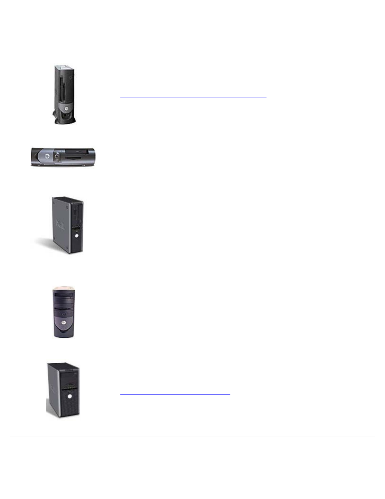
Small Form-Factor Computer
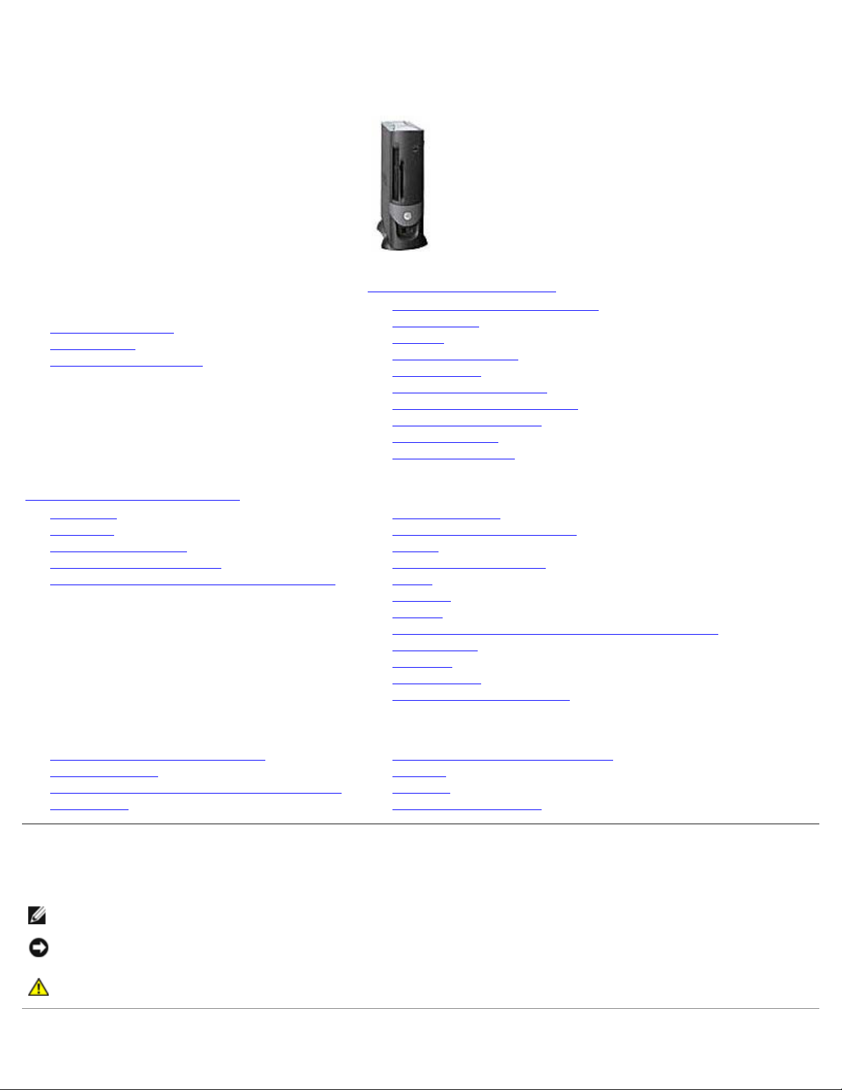
Small Desktop Computer
Desktop Computer
Small Mini-Tower Computer
Mini-Tower Computer
Page 2
Dell™ OptiPlex™ GX280 Systems User's Guide
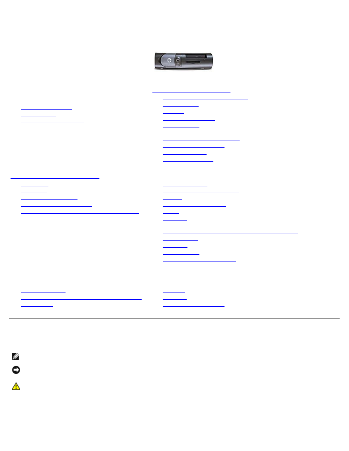
Small Form-Factor
Computer
Documentation for Your
Computer
Finding Information
Specifications
Cleaning Your Computer
About Your Computer
Front View
Back View
Inside Your Computer
System Board Components
Attaching and Removing the Computer Stand
Advanced Features
LegacySelect Technology Control
Manageability
Security
Password Protection
System Setup
Booting to a USB Device
Clearing Forgotten Passwords
Clearing CMOS Settings
Hyper-Threading
Power Management
Adding and Removing Parts
Before You Begin
Opening the Computer Cover
Battery
Chassis Intrusion Switch
Drives
I/O Panel
Memory
PCI and PCI Express Cards and Serial Port Adapters
Power Supply
Processor
System Board
Closing the Computer Cover
Computer and Software Problems
Troubleshooting Tools and Utilities
Solving Problems
Reinstalling Drivers and the Operating System
Getting Help
Additional Information
Microsoft® Windows® XP Features
Glossary
Warranty
FCC Notices (U.S. Only)
Notes, Notices, and Cautions
NOTE: A NOTE indicates important information that helps you make better use of your computer.
NOTICE: A NOTICE indicates either potential damage to hardware or loss of data and tells you how to avoid the
problem.
CAUTION: A CAUTION indicates a potential for property damage, personal injury, or death.
Page 3

Abbreviations and Acronyms
For a complete list of abbreviations and acronyms, see the "Glossary."
If you purchased a Dell™ n Series computer, any references in this document to Microsoft
®
Windows® operating systems are
not applicable.
The Drivers and Utilities CD (ResourceCD), operating system media, and Quick Reference Guides are optional, and as such
may not ship with all computers.
Information in this document is subject to change without notice.
© 2005 Dell Inc. All rights reserved.
Reproduction in any manner whatsoever without the written permission of Dell Inc. is strictly forbidden.
Trademarks used in this text: Dell, the DELL logo, OptiPlex, Inspiron, Dimension, Latitude, Dell Precision , DellNet, TravelLite, Dell OpenManage,
PowerVault, Axim, PowerEdge, PowerConnect, and PowerApp are trademarks of Dell Inc.; Intel, Pentium, and Celeron are registered trademarks of
Intel Corporation; Microsoft, Windows NT, MS- DOS, and Windows are registered trademarks of Microsoft Corporation; IBM and OS/2 are registered
trademarks of International Business Machines Corporation; NetWare and Novell are registered trademarks of Novell, Inc. Bluetooth is a trademark
owned by Bluetooth SIG, Inc. and is used by Dell Inc. under license. ENERGY STAR is a registered trademark of the U.S. Environmental Protection
Agency. As an ENERGY STAR partner, Dell Inc. has determined that this product meets the ENERGY STAR guidelines for energy efficiency.
Other trademarks and trade names may be used in this document to refer to either the entities claiming the marks and names or their products.
Dell Inc. disclaims any proprietary interest in trademarks and trade names other than its own.
Models: DHP, DHS, DCNE, DHM, and DCSM
September 2005 Y2952 Rev. A05
Page 4
Dell™ OptiPlex™ GX280 Systems User's Guide
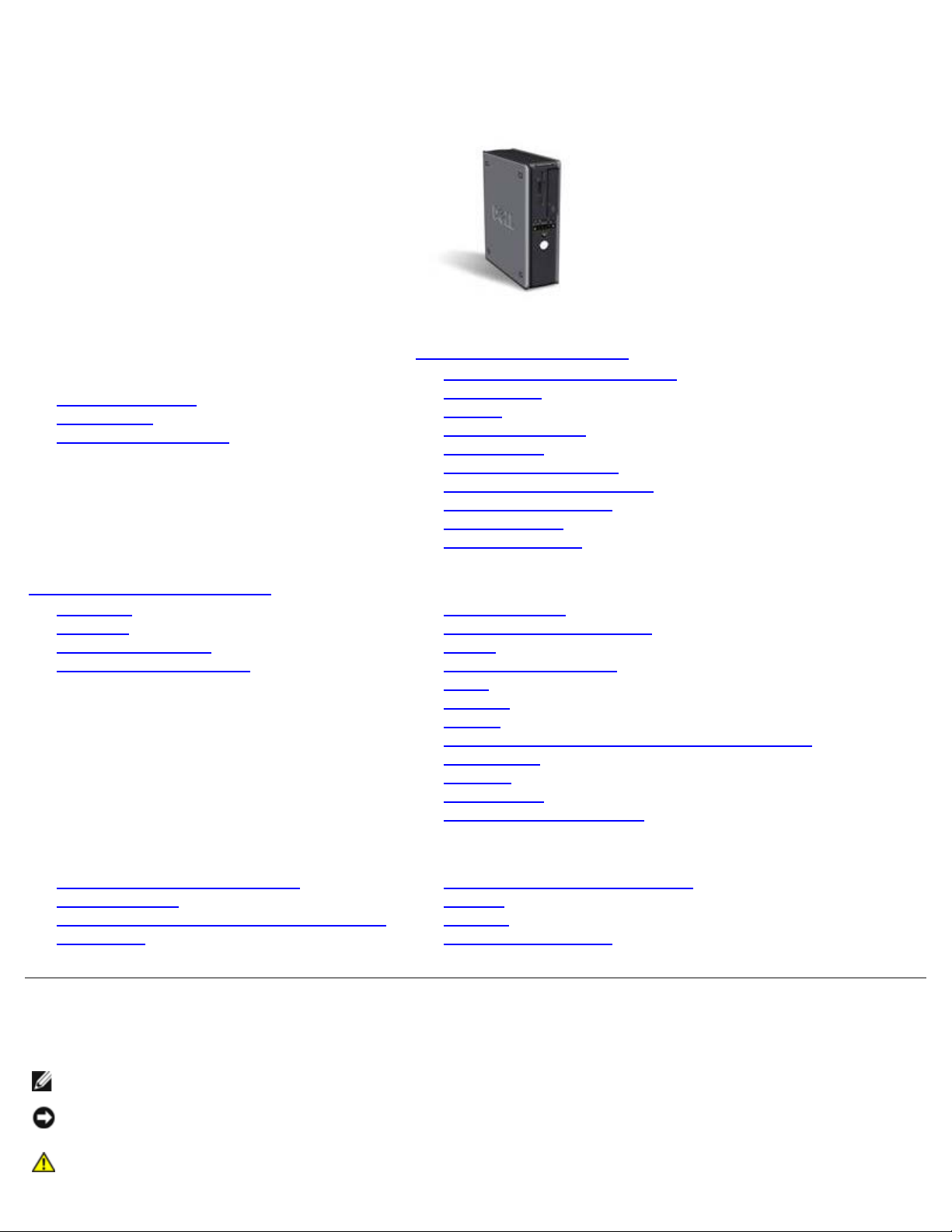
Small Desktop Computer
Documentation for Your
Computer
Finding Information
Specifications
Cleaning Your Computer
About Your Computer
Front View
Back View
Inside Your Computer
System Board Components
Attaching and Removing the Computer Stand
Advanced Features
LegacySelect Technology Control
Manageability
Security
Password Protection
System Setup
Booting to a USB Device
Clearing Forgotten Passwords
Clearing CMOS Settings
Hyper-Threading
Power Management
Adding and Removing Parts
Before You Begin
Opening the Computer Cover
Battery
Chassis Intrusion Switch
Drives
I/O Panel
Memory
PCI and PCI Express Cards and Serial Port Adapters
Power Supply
Processor
System Board
Closing the Computer Cover
Computer and Software Problems
Troubleshooting Tools and Utilities
Solving Problems
Reinstalling Drivers and the Operating System
Getting Help
Additional Information
Microsoft® Windows® XP Features
Glossary
Warranty
FCC Notices (U.S. Only)
Notes, Notices, and Cautions
NOTE: A NOTE indicates important information that helps you make better use of your computer.
NOTICE: A NOTICE indicates either potential damage to hardware or loss of data and tells you how to avoid the
problem.
CAUTION: A CAUTION indicates a potential for property damage, personal injury, or death.
Abbreviations and Acronyms
Page 5

For a complete list of abbreviations and acronyms, see the "Glossary."
If you purchased a Dell™ n Series computer, any references in this document to Microsoft
®
Windows® operating systems are
not applicable.
The Drivers and Utilities CD (ResourceCD), operating system media, and Quick Reference Guides are optional, and as such
may not ship with all computers.
Information in this document is subject to change without notice.
© 2005 Dell Inc. All rights reserved.
Reproduction in any manner whatsoever without the written permission of Dell Inc. is strictly forbidden.
Trademarks used in this text: Dell, the DELL logo, OptiPlex, Inspiron, Dimension, Latitude, Dell Precision , DellNet, TravelLite, Dell OpenManage,
PowerVault, Axim, PowerEdge, PowerConnect, and PowerApp are trademarks of Dell Inc.; Intel, Pentium, and Celeron are registered trademarks of
Intel Corporation; Microsoft, Windows NT, MS- DOS, and Windows are registered trademarks of Microsoft Corporation; IBM and OS/2 are registered
trademarks of International Business Machines Corporation; NetWare and Novell are registered trademarks of Novell, Inc. Bluetooth is a trademark
owned by Bluetooth SIG, Inc. and is used by Dell Inc. under license. ENERGY STAR is a registered trademark of the U.S. Environmental Protection
Agency. As an ENERGY STAR partner, Dell Inc. has determined that this product meets the ENERGY STAR guidelines for energy efficiency.
Other trademarks and trade names may be used in this document to refer to either the entities claiming the marks and names or their products.
Dell Inc. disclaims any proprietary interest in trademarks and trade names other than its own.
Models: DHP, DHS, DCNE, DHM, and DCSM
September 2005 Y2952 Rev. A05
Page 6
Dell™ OptiPlex™ GX280 Systems User's Guide
Desktop Computer
Documentation for Your
Computer
Finding Information
Specifications
Cleaning Your Computer
About Your Computer
Front View
Back View
Inside Your Computer
System Board Components
Advanced Features
LegacySelect Technology Control
Manageability
Security
Password Protection
System Setup
Booting to a USB Device
Clearing Forgotten Passwords
Clearing CMOS Settings
Hyper-Threading
Power Management
Adding and Removing Parts
Before You Begin
Opening the Computer Cover
Battery
Chassis Intrusion Switch
Drives
I/O Panel
Memory
PCI and PCI Express Cards and Serial Port Adapters
Power Supply
Processor
System Board
Closing the Computer Cover
Computer and Software Problems
Troubleshooting Tools and Utilities
Solving Problems
Reinstalling Drivers and the Operating System
Getting Help
Additional Information
Microsoft® Windows® XP Features
Glossary
Warranty
FCC Notices (U.S. Only)
Notes, Notices, and Cautions
NOTE: A NOTE indicates important information that helps you make better use of your computer.
NOTICE: A NOTICE indicates either potential damage to hardware or loss of data and tells you how to avoid the
problem.
CAUTION: A CAUTION indicates a potential for property damage, personal injury, or death.
Page 7

Abbreviations and Acronyms
For a complete list of abbreviations and acronyms, see the "Glossary."
If you purchased a Dell™ n Series computer, any references in this document to Microsoft
®
Windows® operating systems are
not applicable.
The Drivers and Utilities CD (ResourceCD), operating system media, and Quick Reference Guides are optional, and as such
may not ship with all computers.
Information in this document is subject to change without notice.
© 2004 Dell Inc. All rights reserved.
Reproduction in any manner whatsoever without the written permission of Dell Inc. is strictly forbidden.
Trademarks used in this text: Dell, the DELL logo, OptiPlex, Inspiron, Dimension, Latitude, Dell Precision , DellNet, TravelLite, Dell OpenManage,
PowerVault, Axim, PowerEdge, PowerConnect, and PowerApp are trademarks of Dell Inc.; Intel, Pentium, and Celeron are registered trademarks of
Intel Corporation; Microsoft, Windows NT, MS- DOS, and Windows are registered trademarks of Microsoft Corporation; IBM and OS/2 are registered
trademarks of International Business Machines Corporation; NetWare and Novell are registered trademarks of Novell, Inc. Bluetooth is a trademark
owned by Bluetooth SIG, Inc. and is used by Dell Inc. under license. ENERGY STAR is a registered trademark of the U.S. Environmental Protection
Agency. As an ENERGY STAR partner, Dell Inc. has determined that this product meets the ENERGY STAR guidelines for energy efficiency.
Other trademarks and trade names may be used in this document to refer to either the entities claiming the marks and names or their products.
Dell Inc. disclaims any proprietary interest in trademarks and trade names other than its own.
Models: DHP, DHS, DCNE, DHM, and DCSM
September 2005 Y2952 Rev. A05
Page 8

Dell™ OptiPlex™ GX280 Systems User's Guide
Small Mini-Tower
Computer
Documentation for Your
Computer
Finding Information
Specifications
Cleaning Your Computer
About Your Computer
Front View
Back View
Inside Your Computer
System Board Components
Front-Panel Door and Hinge Arms
Advanced Features
LegacySelect Technology Control
Manageability
Security
Password Protection
System Setup
Booting to a USB Device
Clearing Forgotten Passwords
Clearing CMOS Settings
Hyper-Threading
Power Management
Adding and Removing Parts
Before You Begin
Opening the Computer Cover
Battery
Chassis Intrusion Switch
Drives
I/O Panel
Memory
PCI and PCI Express Cards and Serial Port Adapters
Power Supply
Processor
System Board
Closing the Computer Cover
Computer and Software Problems
Troubleshooting Tools and Utilities
Solving Problems
Reinstalling Drivers and the Operating System
Getting Help
Additional Information
Microsoft® Windows® XP Features
Glossary
Warranty
FCC Notices (U.S. Only)
Notes, Notices, and Cautions
NOTE: A NOTE indicates important information that helps you make better use of your computer.
NOTICE: A NOTICE indicates either potential damage to hardware or loss of data and tells you how to avoid the
problem.
CAUTION: A CAUTION indicates a potential for property damage, personal injury, or death.
Page 9

Abbreviations and Acronyms
For a complete list of abbreviations and acronyms, see the "Glossary."
If you purchased a Dell™ n Series computer, any references in this document to Microsoft
®
Windows® operating systems are
not applicable.
The Drivers and Utilities CD (ResourceCD), operating system media, and Quick Reference Guides are optional, and as such
may not ship with all computers.
Information in this document is subject to change without notice.
© 2005 Dell Inc. All rights reserved.
Reproduction in any manner whatsoever without the written permission of Dell Inc. is strictly forbidden.
Trademarks used in this text: Dell, the DELL logo, OptiPlex, Inspiron, Dimension, Latitude, Dell Precision , DellNet, TravelLite, Dell OpenManage,
PowerVault, Axim, PowerEdge, PowerConnect, and PowerApp are trademarks of Dell Inc.; Intel, Pentium, and Celeron are registered trademarks of
Intel Corporation; Microsoft, Windows NT, MS- DOS, and Windows are registered trademarks of Microsoft Corporation; IBM and OS/2 are registered
trademarks of International Business Machines Corporation; NetWare and Novell are registered trademarks of Novell, Inc. Bluetooth is a trademark
owned by Bluetooth SIG, Inc. and is used by Dell Inc. under license. ENERGY STAR is a registered trademark of the U.S. Environmental Protection
Agency. As an ENERGY STAR partner, Dell Inc. has determined that this product meets the ENERGY STAR guidelines for energy efficiency.
Other trademarks and trade names may be used in this document to refer to either the entities claiming the marks and names or their products.
Dell Inc. disclaims any proprietary interest in trademarks and trade names other than its own.
Models: DHP, DHS, DCNE, DHM, and DCSM
September 2005 Y2952 Rev. A05
Page 10
Dell™ OptiPlex™ GX280 Systems User's Guide
Mini-Tower Computer
Documentation for Your
Computer
Finding Information
Specifications
Cleaning Your Computer
About Your Computer
Front View
Back View
Inside Your Computer
System Board Components
Advanced Features
LegacySelect Technology Control
Manageability
Security
Password Protection
System Setup
Booting to a USB Device
Clearing Forgotten Passwords
Clearing CMOS Settings
Hyper-Threading
Power Management
Adding and Removing Parts
Before You Begin
Opening the Computer Cover
Battery
Chassis Intrusion Switch
Drives
I/O Panel
Memory
PCI and PCI Express Cards and Serial Port Adapters
Power Supply
Processor
System Board
Closing the Computer Cover
Computer and Software Problems
Troubleshooting Tools and Utilities
Solving Problems
Reinstalling Drivers and the Operating System
Getting Help
Additional Information
Microsoft® Windows® XP Features
Glossary
Warranty
FCC Notices (U.S. Only)
Notes, Notices, and Cautions
NOTE: A NOTE indicates important information that helps you make better use of your computer.
NOTICE: A NOTICE indicates either potential damage to hardware or loss of data and tells you how to avoid the
problem.
CAUTION: A CAUTION indicates a potential for property damage, personal injury, or death.
Page 11

Abbreviations and Acronyms
For a complete list of abbreviations and acronyms, see the "Glossary."
If you purchased a Dell™ n Series computer, any references in this document to Microsoft
®
Windows® operating systems are
not applicable.
The Drivers and Utilities CD (ResourceCD), operating system media, and Quick Reference Guides are optional, and as such
may not ship with all computers.
Information in this document is subject to change without notice.
© 2005 Dell Inc. All rights reserved.
Reproduction in any manner whatsoever without the written permission of Dell Inc. is strictly forbidden.
Trademarks used in this text: Dell, the DELL logo, OptiPlex, Inspiron, Dimension, Latitude, Dell Precision , DellNet, TravelLite, Dell OpenManage,
PowerVault, Axim, PowerEdge, PowerConnect, and PowerApp are trademarks of Dell Inc.; Intel, Pentium, and Celeron are registered trademarks of
Intel Corporation; Microsoft, Windows NT, MS- DOS, and Windows are registered trademarks of Microsoft Corporation; IBM and OS/2 are registered
trademarks of International Business Machines Corporation; NetWare and Novell are registered trademarks of Novell, Inc. Bluetooth is a trademark
owned by Bluetooth SIG, Inc. and is used by Dell Inc. under license. ENERGY STAR is a registered trademark of the U.S. Environmental Protection
Agency. As an ENERGY STAR partner, Dell Inc. has determined that this product meets the ENERGY STAR guidelines for energy efficiency.
Other trademarks and trade names may be used in this document to refer to either the entities claiming the marks and names or their products.
Dell Inc. disclaims any proprietary interest in trademarks and trade names other than its own.
Models: DHP, DHS, DCNE, DHM, and DCSM
September 2005 Y2952 Rev. A05
Page 12
Back to Contents Page
Finding Information
Dell™ OptiPlex™ GX280 Systems User's Guide
What Are You Looking For? Find it Here
A diagnostic program
for my computer
Drivers for my
computer
My computer
documentation
My device
documentation
How to set up my
computer
Troubleshooting
information
How to run the Dell
Diagnostics
Error codes and
diagnostic lights
Tools and utilities
Drivers and Utilities CD (also known as the ResourceCD)
Documentation and drivers are already installed on your computer. You can use the CD to
reinstall drivers, run the Dell Diagnostics, or access your documentation.
Readme files may be included on your CD to provide last-minute updates about technical
changes to your computer or advanced technical-reference material for technicians or
experienced users.
NOTE: The Drivers and Utilities CD is optional and may not ship with all computers.
Quick Reference Guide
NOTE: This document is available as a PDF at support.dell.com.
NOTE: The Quick Reference Guide is optional and may not ship
with all computers.
Warranty information
Safety instructions
Regulatory information
Ergonomics
information
End User License
Agreement
How to remove and
replace parts
Technical
specifications
How to configure
Dell™ Product Information Guide
User's Guide
Microsoft® Windows® XP Help and Support Center
Page 13
system settings
1. Click the Start button and click Help and Support.
How to troubleshoot
and solve problems
Operating system
updates and patches
2. Click User's and system guides and click User's guides.
Desktop System Software (DSS)
The DSS is located on the Drivers and Utilities CD and on the Dell Support website.
Service Tag and
Express Service Code
Microsoft Windows
License Label
Latest drivers for my
computer
Answers to technical
service and support
questions
Online discussions
with other users and
technical support
Documentation for my
computer
Service call status and
support history
Top technical issues
for my computer
Frequently asked
questions
File downloads
Details on my
computer
configuration
Service contract for
my computer
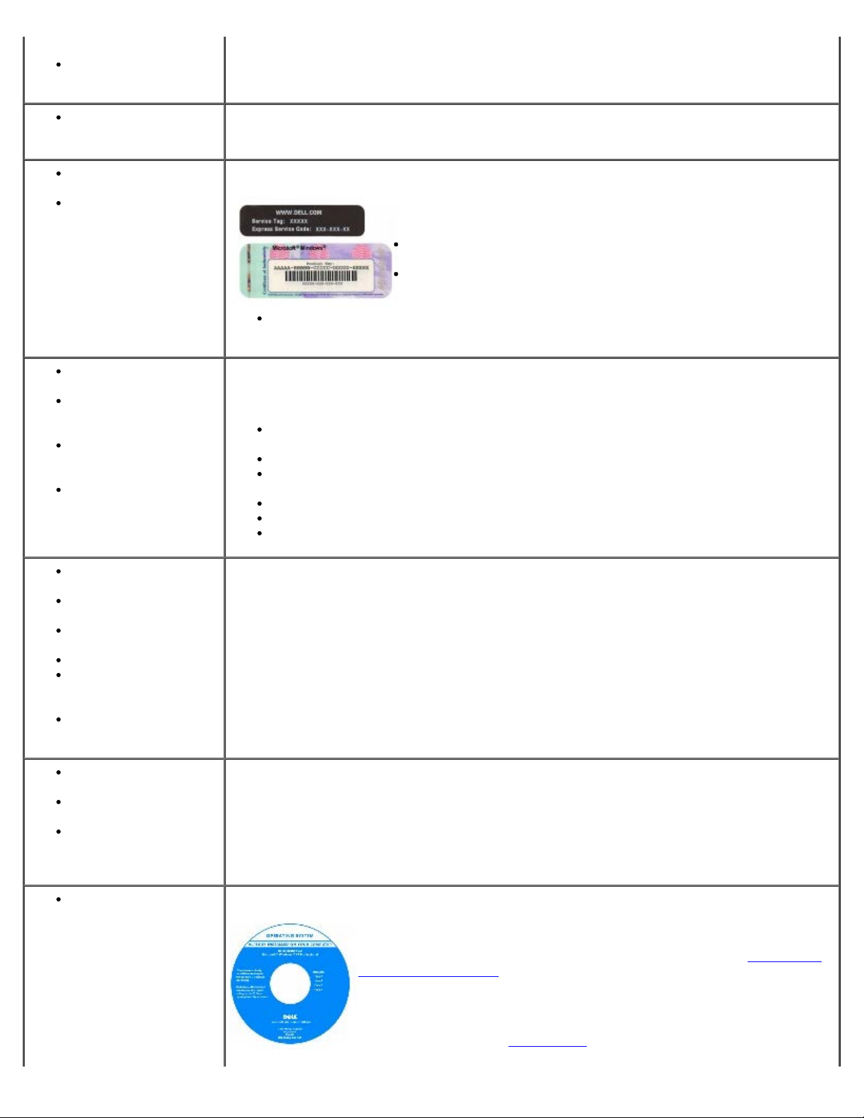
Service Tag and Microsoft Windows License
These labels are located on your computer.
Use the Service Tag to identify your computer when you use
support.dell.com or contact technical support.
Enter the Express Service Code to direct your call when
contacting technical support. The Express Service Code is not
available in all countries.
Use the number on the Microsoft Windows License Label if you reinstall your operating
system.
Dell Support Website — support.dell.com
The Dell Support website provides several online tools, including:
Solutions — Troubleshooting hints and tips, articles from technicians, and online
courses
Community — Online discussion with other Dell customers
Upgrades — Upgrade information for components, such as memory, the hard drive,
and the operating system
Customer Care — Contact information, order status, warranty, and repair information
Downloads — Drivers, patches, and software updates
Reference — Computer documentation, product specifications, and white papers
Dell Premier Support Website — premiersupport.dell.com
The Dell Premier Support website is customized for corporate, government, and education
customers. This website may not be available in all regions.
How to use Windows
XP
Documentation for my
computer
Documentation for
devices (such as a
modem)
How to reinstall my
operating system
Windows Help and Support Center
1. Click the Start button and click Help and Support.
2. Type a word or phrase that describes your problem and click the arrow icon.
3. Click the topic that describes your problem.
4. Follow the instructions on the screen.
Operating System CD
The operating system is already installed on your computer. To reinstall
your operating system, use the Operating System CD. See "
Microsoft Windows XP" for reinstallation instructions.
After you reinstall your operating system, use the Drivers and Utilities CD
to reinstall drivers for the devices that came with your computer.
Your operating system
license label is located on your computer.
Reinstalling
Page 14

NOTE: The operating system media is optional and may not ship with all computers
Back to Contents Page
Page 15
Back to Contents Page
Yellow — A good connection exists
Specifications
Dell™ OptiPlex™ GX280 Systems User's Guide
Microprocessor
Microprocessor type
Level 1 (L1) cache 32 KB
Level 2 (L2) cache 1 MB pipelined-burst, eight-way set
Memory
Type 400 & 533 MHz DDR2 SDRAM
Memory connectors small form-factor computer: 2
Memory capacities 128 MB, 256 MB, 512 MB, or 1 GB non-
Minimum memory dual-channel: 256 MB
Maximum memory small form-factor computer: 2 GB
Intel® Pentium
future Dell-supported upgrades.
associative, write-back SRAM
small desktop computer: 4
desktop computer: 4
small mini-tower computer: 4
mini-tower computer: 4
ECC
single-channel: 128 MB
small desktop computer: 4 GB
desktop computer: 4 GB
small mini-tower computer: 4 GB
mini-tower computer: 4 GB
®
4; design provides for
BIOS address F0000h
Computer Information
Chipset Intel Grantsdale
Data bus width 64 bits
Address bus width 32 bits
DMA channels eight
Interrupt levels 24
BIOS chip (NVRAM) 4-Mb
Memory speed 400 & 533 MHz
NIC integrated network interface with ASF
1.03 support as defined by DMTF.
Capable of 10/100/1000 communication:
Green — A good connection exists
between a 10-Mbps network and
the computer.
Orange — A good connection exists
between a 100-Mbps network and
the computer.
Page 16
between a 1 Gb (or 1000-Mbps)
network and the computer.
Off — The computer is not
detecting a physical connection to
the network.
Video
Type integrated Intel Extreme Graphics or PCI
Express x16 DVI video card
Audio
Type AC97, Sound Blaster emulation
Stereo conversion 16-bit analog-to-digital; 20-bit digital-to-
analog
Controllers
Drives small form-factor: one serial ATA
controller supporting one device and one
parallel Ultra ATA/100 IDE supporting two
devices per channel with one channel
small desktop: one serial ATA controllers
supporting one device each and one
parallel Ultra ATA/100 IDE supporting two
devices per channel with one channel
desktop: two serial ATA controllers
supporting one device each and one
parallel Ultra ATA/100 IDE supporting two
devices per channel with one channel.
small mini-tower: two serial ATA
controllers supporting one device each
and one parallel Ultra ATA/100 IDE
supporting two devices per channel with
one channel
mini-Tower: two serial ATA controllers
supporting one device each and one
parallel Ultra ATA/100 IDE supporting two
devices per channel with one channel
Expansion Bus
Bus type PCI 2.2
SATA 1.0a
USB 2.0
PCI Express 1.0a
Bus speed PCI: 33 MHz
SATA: 1.5 Gbps
USB: 480 Mbps
PCI Express x1: 5 Gbps
PCI Express x16: 80 Gbps
Small Form-Factor computer low-profile cards supported
PCI
connector one
Page 17

connector size 120 pins
connector data width (maximum) 32 bits
PCI Express
connector one x16
connector size 164 pins
connector data width (maximum) 16 PCI Express lanes
Small Desktop computer half-length cards supported
PCI
connectors one or two (depending on purchase)
connector size 120 pins
connector data width (maximum) 32 bits
PCI Express
connector one x16 and an optional x1
connector size 120 pins (x16) and an optional 36 pins
(x1)
connector data width (maximum) 16 PCI Express lanes (x16) and an
optional one PCI Express lane (x1)
Desktop computer half-height cards supported
half-length, full-height cards supported
with optional with card cage
PCI
connectors two (without card cage)
two (with card cage)
connector size 120 pins
connector data width
(maximum)
PCI Express
connectors one x16
connector size 120 pins (x16)
connector data width 16 PCI Express lanes (x16)
Small Mini-Tower full-height cards supported
PCI
connectors three
connector size 120 pins
connector data width (maximum) 32 bits
PCI Express
connector one x1 and one x16
32 bits
connector size 36 pins (x1) and 120 pins (x16)
connector data width (maximum) one PCI Express lane (x1) and 16 PCI
Express lanes (x16)
Mini-Tower full-height cards supported
PCI
connectors two
Page 18

connector size 120 pins
connector data width
(maximum)
PCI Express
connectors one x1 and one x16
connector size 36 pins (x1) and 120 pins (x16)
32 bits
connector date width
(maximum)
Drives
Externally accessible:
Small Form-Factor computer one bay for a slimline floppy drive
Small Desktop computer one 3.5-inch bay
Desktop computer one 3.5-inch drive
Small Mini-Tower computer two 3.5-inch drive bays
Mini-Tower computer one 3.5-inch drive bay
Internally accessible:
Small Form-Factor computer one bay for a 1-inch-high hard drive
Small Desktop computer one bay for a 1-inch-high hard drive
one PCI Express lane (x1) and 16 PCI
Express lanes (x16)
one bay for a slimline CD/DVD drive
one 5.25-inch bay
one bay for CD/DVD or optional second
Hard Drive
two 5.25-inch drive bays
two 5.25-inch drive bays
Desktop computer one bay for a 1-inch-high hard drive
Small Mini-Tower computer two bays for 1-inch high hard drives
Mini-Tower computer two bays for 1-inch high hard drives
Connectors
External connectors:
Serial 9-pin connector; 16550C-compatible
Parallel 25-hole connector (bidirectional)
Video 15-hole connector
Network adapter RJ45 connector
Optional PS/2 with secondary serial
port adapter
USB two front-panel and six back-panel USB
Audio three connectors for line-in, line-out, and
small form-factor computer: one 6-pin
mini-DIN with a Y-adapter
small desktop, small mini-tower, desktop,
and mini-tower: two 6-pin mini-DINs
2.0–compliant connectors
microphone; one front-panel connector
for headphones
System board connectors:
Page 19
Primary IDE drive 40-pin connector
Serial ATA small form-factor computer: one 7-pin
Floppy drive 34-pin connector
Serial 12-pin connector for optional second
Fan 5-pin connector
PCI 2.2 120-pin connector
CD drive audio interface 4-pin connector
Front audio 10-pin connector (For the optional audio
Front panel 40-pin connector
Key Combinations
<Ctrl><Alt><Del> If running Microsoft® Windows® XP,
connector
small desktop computer: one 7-pin
connectors
desktop computer: two 7-pin connectors
small mini-tower: two 7-pin connectors
mini-tower: two 7-pin connectors
serial port card
customer kit)
brings up the Windows Security window.
If in MS-DOS® mode, restarts (reboots)
the computer
<F2> or <Ctrl><Alt><Enter> starts embedded system setup (during
start-up only)
<Ctrl><Alt><b> automatically starts the computer from
the network environment specified by the
remote boot environment (PXE) rather
than from one of the devices in the
system setup Boot Sequence option
(during start-up only)
<F12> or <Ctrl><Alt><F8> displays a boot device menu that allows
the user to enter a device for a single
boot (during start-up only) as well as
options to run hard-drive and system
diagnostics
Controls and Lights
Power control push button
Power light green light—blinking green in sleep state;
solid green for power-on state
amber light—blinking amber indicates a
problem with an installed device; solid
amber indicates an internal power
problem (see
Power Problems)
Hard-drive access light green
Link integrity light (on integrated network
adapter)
Activity light (on integrated network
adapter)
Diagnostic lights small form-factor, small desktop, and
green light for 10-Mb operation; orange
light for 100-Mb operation; yellow light
for a 1000-Mb (1-Gb) operation
yellow blinking light
Page 20
small mini-tower computers: four lights
on the back panel
desktop and mini-towercomputers: four
lights on the front panel
Standby power light AUX_PWR on the system board
Power
DC power supply:
Wattage small form-factor computer: 160 W
small desktop computer: 210 W
desktop computer: 280 W
small mini-tower computer with processor
speeds of 3.2 GHz or lower: 250 W
small mini-tower computer with processor
speeds of 3.4 GHz or higher: 305 W
mini-tower computer: 305 W
Heat dissipation small form-factor computer: 546 BTU/hr
small desktop computer: 717 BTU/hr
desktop computer: 150W max
small mini-tower computer with processor
speeds of 3.2 GHz or lower: 853 BTU/hr
small mini-tower computer with processor
speeds of 3.4 GHz or higher: 1041 BTU/hr
mini-tower computer: 150W max
Voltage fixed-voltage power supply—110 V at
50/60 Hz
manual selection and auto-sensing power
supplies—90 to 135 V at 50/60 Hz; 180 to
265 V at 50/60 Hz; 100 V at 50/60 Hz for
Japanese computers
Backup battery 3-V CR2032 lithium coin cell
Physical
Small Form-Factor computer:
Height 9.0 cm (3.57 inches)
Width 31.9 cm (12.54 inches)
Depth 35.4 cm (13.93 inches)
Weight 6 kg (14 lbs)
Small Desktop computer:
Height 10.6 cm (4.2 inches)
Width 38.9 cm (15.3 inches)
Depth 43.2 cm (17 inches)
Weight 9.9 kg (22 lbs)
Desktop computer
Height 11.4 cm (4.5 inches)
Width 39.9 cm (15.7 inches)
Depth 35.3 cm (13.9) inches
Weight 10.4 kg (23 lbs)
Small Mini-Tower computer:
Page 21
Height 42.5 cm (16.7 inches)
Width 18.1 cm (7.1 inches)
Depth 44.7 cm (17.6 inches)
Weight 12.7 kg (28 lbs)
Mini-Tower computer
Height 41.4 cm (16.3 inches)
Width 18.5 cm (7.3 inches)
Depth 43.9 cm (17.3 inches)
Weight 12.34 kg (27.2 lbs)
Environmental
Temperature:
Operating 10° to 35°C (50° to 95°F)
NOTE: At 35°C (95°F), the maximum
operating altitude is 914 m (3000 ft).
Storage –40° to 65°C (–40° to 149°F)
Relative humidity 20% to 80% (noncondensing)
Maximum vibration:
Operating 0.25 G at 3 to 200 Hz at 0.5 octave/min
Storage 0.5 G at 3 to 200 Hz at 1 octave/min
Maximum shock:
Operating bottom half-sine pulse with a change in
Storage 27-G faired square wave with a velocity
Altitude:
Operating –15.2 to 3048 m (–50 to 10,000 ft)
Storage –15.2 to 10,668 m (–50 to 35,000 ft)
Back to Contents Page
velocity of 20 inches/sec (50.8 cm/sec)
change of 200 inches/sec (508 cm/sec)
Page 22

Back to Contents Page
Cleaning Your Computer
Dell™ OptiPlex™ GX280 Systems User's Guide
CAUTION: Before you begin any of the procedures in this section, follow the safety instructions located in
the Product Information Guide.
Computer, Keyboard, and Monitor
CAUTION: Before you clean your computer, disconnect the computer from the electrical outlet. Clean your
computer with a soft cloth dampened with water. Do not use liquid or aerosol cleaners, which may contain
flammable substances.
Use a vacuum cleaner with a brush attachment to gently remove dust from the slots and holes on your computer and
from between the keys on the keyboard.
NOTICE: Do not wipe the display screen with any soap or alcohol solution. Doing so may damage the antiglare
coating.
To clean your monitor screen, lightly dampen a soft, clean cloth with water. If possible, use a special screen-cleaning
tissue or solution suitable for the monitor's antistatic coating.
Wipe the keyboard, computer, and plastic part of the monitor with a soft cleaning cloth moistened with a solution of
three parts water and one part dish washing detergent.
Do not soak the cloth or let water drip inside your computer or keyboard.
Mouse
If your screen cursor skips or moves abnormally, clean the mouse. To clean a non-optical mouse:
1. Turn the retainer ring on the underside of your mouse counterclockwise, and then remove the ball.
2. Wipe the ball with a clean, lint-free cloth.
3. Blow carefully into the ball cage to dislodge dust and lint.
4. If the rollers inside the ball cage are dirty, clean the rollers with a cotton swab moistened lightly with isopropyl alcohol.
5. Re-center the rollers in their channels if they are misaligned. Ensure that fluff from the swab is not left on the rollers.
6. Replace the ball and retainer ring, and turn the retainer ring clockwise until it clicks into place.
Floppy Drive
NOTICE: Do not attempt to clean drive heads with a swab. You might accidentally mis-align the heads, which prevents
the drive from operating.
Clean your floppy drive using a commercially available cleaning kit. These kits contain pretreated floppy disks to remove
contaminants that accumulate during normal operation.
Page 23

CDs and DVDs
NOTICE: Always use compressed air to clean the lens in the CD/DVD drive, and follow the instructions that come with
the compressed air. Never touch the lens in the drive.
If you notice problems, such as skipping, with the playback quality of your CDs or DVDs, try cleaning the discs.
1. Hold the disc by its outer edge. You can also touch the inside edge of the center hole.
NOTICE: To prevent damaging the surface, do not wipe in a circular motion around the disc.
2. With a soft, lint-free cloth, gently wipe the bottom of the disc (the unlabeled side) in a straight line from the center to
the outer edge of the disc.
For stubborn dirt, try using water or a diluted solution of water and mild soap. You can also purchase commercial
products that clean discs and provide some protection from dust, fingerprints, and scratches. Cleaning products for CDs
are safe to use on DVDs.
Back to Contents Page
Page 24
Back to Contents Page
Dell OpenManage IT Assistant
Advanced Features
Dell™ OptiPlex™ GX280 Systems User's Guide
LegacySelect Technology Control
Manageability
Security
Password Protection
System Setup
Booting to a USB Device
Clearing Forgotten Passwords
Clearing CMOS Settings
Hyper-Threading
Power Management
LegacySelect Technology Control
LegacySelect technology control offers legacy-full, legacy-reduced, or legacy-free solutions based on common platforms,
hard-drive images, and help desk procedures. Control is provided to the administrator through system setup, Dell
OpenManage™ IT Assistant, or Dell™ custom factory integration.
LegacySelect allows administrators to electronically activate or deactivate connectors and media devices that include serial
and USB connectors, a parallel connector, a floppy drive, PCI slots, and a PS/2 mouse. Connectors and media devices that are
deactivated make resources available. You must restart the computer to effect the changes.
Manageability
Alert Standard Format
ASF is a DMTF management standard that specifies "pre-operating system" or "operating system-absent" alerting techniques.
The standard is designed to generate an alert on potential security and fault conditions when the operating system is in a
sleep state or the system is powered down. ASF is designed to supersede previous operating system-absent alerting
technologies.
Your computer supports the following ASF version 1.03 alerts and remote capabilities:
Alert Description
Chassis: Chassis Intrusion – Physical Security
Violation/Chassis Intrusion – Physical Security
Violation Event Cleared
CPU: Emergency Shutdown Event
Cooling Device: Generic Critical Fan
Failure/Generic Critical Fan Failure Cleared
Temperature: Generic Critical Temperature
Problem/Generic Critical Temperature Problem
Cleared
Battery Low
For more information about Dell's ASF implementation, see the ASF User's Guide and the ASF Administrator's Guide, which
are available on the Dell Support website at support.dell.com.
The computer chassis with the chassis intrusion feature
installed and enabled has been opened or the chassis
intrusion alert has been cleared.
The processor temperature is too hot and the power supply
has shut down.
The fan speed (rpm) is out of limits or the fan speed (rpm)
problem has been resolved.
The computer temperature is out of limits or the computer
temperature problem has been resolved.
The system battery has reached a voltage of 2.2V or lower.
Page 25

IT Assistant configures, manages, and monitors computers and other devices on a corporate network. IT Assistant manages
to select Reset, and then choose On, On-Silent, or Off.
assets, configurations, events (alerts), and security for computers equipped with industry-standard management software. It
supports instrumentation that conforms to SNMP, DMI, and CIM industry standards.
Dell OpenManage Client instrumentation, which is based on DMI and CIM, is available for your computer. For information on
IT Assistant, see the Dell OpenManage IT Assistant User's Guide available on the Dell Support website at support.dell.com.
Dell OpenManage Client Instrumentation
Dell OpenManage Client Instrumentation is software that enables remote management programs such as IT Assistant to do
the following:
Access information about your computer, such as how many processors it has and what operating system it is running
Monitor the status of your computer, such as listening for thermal alerts from temperature probes or hard-drive failure
alerts from storage devices
Change the state of your computer, such as updating its BIOS or shutting it down remotely
A managed system is one that has Dell OpenManage Client Instrumentation set up on a network that uses IT Assistant. For
information about Dell OpenManage Client Instrumentation, see the Dell OpenManage Client Instrumentation User's Guide
available on the Dell Support website at support.dell.com.
Security
Chassis Intrusion Detection
NOTE: When the admin password is enabled, you must know the admin password before you can reset the Chassis
Intrusion setting.
This feature, if installed and enabled, detects that the chassis was opened and alerts the user. To change the Chassis
Intrusion setting:
Enter system setup.
1.
2. Press the down-arrow keys to move to the System Security option.
3. Press <Enter> to access the System Security option's pop-up menu.
4. Press the down-arrow key to move to the Chassis Intrusion setting.
5. Press <Enter> to select an option setting.
6. Press <Enter> again after you update the option setting.
7. Exit and save system setup.
Option Settings
On — If the computer cover is opened, the setting changes to Detected, and the following alert message displays
during the boot routine at the next computer start-up:
Alert! Cover was previously removed.
To reset the Detected setting,
enter system setup. In the Chassis Intrusion option, press the left- or right-arrow key
Page 26

On-Silent (default) — If the computer cover is opened, the setting changes to Detected. No alert message appears
during the boot sequence at the next computer start-up.
Off — No intrusion monitoring occurs and no messages appear.
Padlock Ring and Security Cable Slot
Use one of the following methods to secure your computer:
Use a padlock alone or a padlock and looped security cable with the padlock ring.
A padlock alone prevents the computer from being opened.
A security cable looped around a stationary object is used in conjunction with a padlock to prevent unauthorized
movement of the computer.
Attach a commercially available antitheft device to the security cable slot on the back of the computer.
NOTE: Before you purchase an antitheft device, make sure that it works with the security cable slot on your computer.
Antitheft devices usually include a segment of metal-stranded cable with an attached locking device and key. The
documentation that comes with the device contains instructions for installing it.
Password Protection
NOTICE: Although passwords provide security for the data on your computer, they are not foolproof. If your data
requires more security, it is your responsibility to obtain and use additional forms of protection, such as data
encryption programs.
System Password
NOTICE: If you leave your computer running and unattended without having a system password assigned, or if you
leave your computer unlocked so that someone can disable the password by changing a jumper setting, anyone can
access the data stored on your hard drive.
Option Settings
You cannot change or enter a new system password if either of the following two options is displayed:
Set — A system password is assigned.
Disabled — The system password is disabled by a jumper setting on the system board.
You can only assign a system password when the following option is displayed:
Not Set — No system password is assigned and the password jumper on the system board is in the enabled position
(the default).
Assigning a System Password
To escape from the field without assigning a system password, press <Tab> or the <Shift><Tab> key combination to move
Page 27

to another field, or press <Esc> at any time before you complete step 5.
1. Enter system setup and verify that Password Status is set to Unlocked.
2. Highlight System Password, and then press the left- or right-arrow key.
The option heading changes to Enter Password, followed by an empty 32-character field in square brackets.
3. Type your new system password.
You can use up to 32 characters. To erase a character when entering your password, press <Backspace> or the leftarrow key. The password is not case sensitive.
Certain key combinations are not valid. If you enter one of these combinations, the speaker emits a beep.
As you press each character key (or the spacebar for a blank space), a placeholder appears in the field.
4. Press <Enter>.
If the new system password is less than 32 characters, the whole field fills with placeholders. Then the option heading
changes to Verify Password, followed by another empty 32-character field in square brackets.
5. To confirm your password, type it a second time and press <Enter>.
The password setting changes to Set.
6. Exit system setup.
Password protection takes effect when you restart the computer.
Typing Your System Password
When you start or restart your computer, one of the following prompts appears on the screen.
If Password Status is set to Unlocked:
Type in the password and
- press <ENTER> to leave password security enabled.
- press <CTRL><ENTER> to disable password security.
Enter password:
If Password Status is set to Locked:
Type the password and press <Enter>.
If you have assigned an admin password, the computer accepts your admin password as an alternate system password.
If you type a wrong or incomplete system password, the following message appears on the screen:
** Incorrect password. **
If you again type an incorrect or incomplete system password, the same message appears on the screen. The third and
subsequent times you type an incorrect or incomplete system password, the computer displays the following message:
** Incorrect password. **
Number of unsuccessful password attempts: 3
System halted! Must power down.
Even after your computer is turned off and on, the previous message is displayed each time you type an incorrect or
incomplete system password.
NOTE: You can use Password Status in conjunction with System Password and Admin Password to further
protect your computer from unauthorized changes.
Deleting or Changing an Existing System Password
Page 28

1. Enter system setup and verify that Password Status is set to Unlocked.
2. Restart your computer.
3. When prompted, type the system password.
4. Press <Ctrl><Enter> to disable the existing system password.
5. Confirm that Not Set is displayed for the System Password option.
If Not Set is displayed, the system password is deleted. If Not Set is not displayed, press <Alt><b> to restart the
computer, and then repeat
step 3 through step 5.
To assign a new password, follow the procedure in "
6. Exit system setup.
Assigning a System Password."
Admin Password
Option Settings
You cannot change or enter a new admin password if either of the following two options is displayed:
Set — An admin password is assigned.
Disabled — The admin password is disabled by a jumper setting on the system board.
You can only assign an admin password when the following option is displayed:
Not Set — No admin password is assigned and the password jumper on the system board is in the enabled position
(the default).
Assigning an Admin Password
The admin password can be the same as the system password.
NOTE: If the two passwords are different, the admin password can be used as an alternate system password.
However, the system password cannot be used in place of the admin password.
Enter system setup and verify that Admin Password is set to Not Set.
1.
2. Highlight Admin Password and press the left- or right-arrow key.
The computer prompts you to type and verify the password. If a character is not permitted, the computer emits a
beep.
3. Type and then verify the password.
After you verify the password, the Admin Password setting changes to Set. The next time you enter system setup,
the computer prompts you for the admin password.
4. Exit system setup.
A change to Admin Password becomes effective immediately (no need to restart the computer).
Page 29

Operating Your Computer With an Admin Password Enabled
When you enter system setup, the Admin Password option is highlighted, prompting you to type the password.
If you do not type the correct password, the computer lets you view, but not modify, system setup options.
NOTE: You can use Password Status in conjunction with Admin Password to protect the system password from
unauthorized changes.
Deleting or Changing an Existing Admin Password
To change an existing admin password, you must know the admin password.
Enter system setup.
1.
2. Type the admin password at the prompt.
3. Highlight Admin Password and press the left- or right-arrow key to delete the existing admin password.
The setting changes to Not Set.
To assign a new admin password, perform the steps in "
4. Exit system setup.
Assigning an Admin Password."
Disabling a Forgotten Password and Setting a New Password
To reset system and/or admin passwords, see "Clearing Forgotten Passwords."
System Setup
Overview
Use system setup as follows:
To change the system configuration information after you add, change, or remove any hardware in your computer
To set or change a user-selectable option such as the user password
To read the current amount of memory or set the type of hard drive installed
Before you use system setup, it is recommended that you write down the system setup screen information for future
reference.
Entering System Setup
1. Turn on (or restart) your computer.
2. When the blue DELL™ logo appears, press <F2> immediately.
If you wait too long and the operating system logo appears, continue to wait until you see the Microsoft® Windows®
desktop. Then
shut down your computer and try again.
Page 30

System Setup Screens
The system setup screen displays current or changeable configuration information for your computer. Information on the
screen is divided into three areas: the options list, active options field, and key functions.
Options List —
This field appears
on the left side of
the system setup
window. The field
is a scrollable list
containing
features that
define the
configuration of
your computer,
including
installed
hardware, power
conservation,
and security
features.
Scroll up and
down the list by
using the up and
down arrow keys.
As an option is
highlighted, the
Option Field
displays more
information
about that option
and the option's
current and
available
settings.
Option
Field —
This field
contains
information
about each
option. In
this field
you can
view your
current
settings
and make
changes to
your
settings.
Use the
right and
left arrow
keys to
highlight
an option.
Press
<Enter> to
make that
selection
active.
Key
Functions
— This
field
appears
below the
Option
Field and
lists keys
and their
functions
within the
active
system
setup field.
Page 31

System Setup Options
NOTE: Depending on your computer and installed devices, the items listed in this section may or may not appear.
System
System
Info
CPU Info
Memory
Info
Date/Time
Boot
Sequence
Lists the computer
name, BIOS version,
and service tag.
Identifies whether
the computer's
processor supports
Hyper-threading and
identifies the CPU
speed, bus speed,
clock speed, and L2
cache.
Indicates amount of
installed memory,
computer memory
speed, amount of
video memory, size
of the display cache,
and channel mode
(dual or single).
Displays current
date and time
settings.
The computer
attempts to boot
from the sequence
of devices specified
in this list.
Drives
Diskette
Drive
Drive 0
through
Drive n
This option enables
or disables the
floppy drive. The
options are Off,
Internal, USB, and
Read Only.
Identifies and
enables and disables
the drives attached
to the SATA or IDE
connectors on the
system board and
lists the capacities
for the hard drives.
NOTE: These
options appear as
Drive 0 through
Drive 3 for the
small form-factor,
small desktop and
desktop computers
and Drive 0 though
Drive 5 for the
small mini-tower
and tower
computers.
Page 32

Configures the serial
ATA controller's
operating mode.
Normal enables the
serial ATA controller
to operate in its
Drive
Controller
Error
Reporting
Onboard Devices
serial ATA native
mode only.
Compatible
enables the serial
ATA controller to
operate in
serial/parallel ATA
combination mode.
This setting
determines whether
hard drive errors
are reported or not
during system
setup.
Audio
Controller
Mouse Port
NIC
Controller
Enables or disables
the onboard audio
controller
Enables or disables
the serial mouse
port. (This setting
appears only if an
optional serial port
adapter is installed.)
You can set the NIC
to On (default), Off,
or On w/ PXE.
When the On w/
PXE setting is active
(available only for
the future boot
process), the
computer prompts
the user to press
<Ctrl><Alt><b>.
Pressing this key
combination causes
a menu to display
that allows you to
select a method for
booting from a
network server. If a
boot routine is not
available from the
network server, the
system attempts to
boot from the next
device in the boot
sequence list.
This option sets the
operating mode for
the built-in parallel
port. The settings
are Off, AT, PS/2
(default), EPP, and
ECP.
AT - the port
is configured
Page 33

LPT Port
for IBM AT
Mode
LPT Port
Address
compatibility
PS/2 - the
port is
configured for
IBM PS/2
compatibility
EPP enhanced
parallel port
protocol
ECP extended
capability port
protocol
This option sets the
address that the
built-in parallel port
uses. The settings
are 378h (default),
278h, and 3BCh.
PCI Slots
Serial
Port #1
Serial
Port #2
USB
Enables or disables
the PCI slots.
Auto, the default
setting,
automatically
configures a
connector to a
particular
designation (COM1
or COM3).
Auto, the default
setting,
automatically
configures a
connector to a
particular
designation (COM1
or COM3). (This
setting appears only
if an optional serial
port adapter is
installed.)
USB devices are
detected and
supported in the
operating system
when this option is
set to On.
USB
Disable
Performance
Hyperthreading
Enables or disables
the front USB
connectors. The
default setting is
On. To disable the
front connectors,
select Off.
If your computer's
processor supports
hyper-threading,
this option appears
in the Options List.
Page 34

HDD
Quiet - the
Acoustic
Mode
hard drive
operates at
its most quiet
setting.
Performance
- the hard
drive
operates at
its maximum
speed.
Bypass
(default) your
computer
does not test
or change the
current
acoustics
mode setting.
Suggested the hard drive
operates at
the level
suggested by
the drive
manufacturer.
Security
NOTE: Switching to
performance mode
may cause the drive
to be noisier, but its
performance is not
affected.
Changing the
acoustics setting
does not alter your
hard drive image.
This section displays
available system
security options.
Security" for
See "
more information.
This option provides
restricted access to
the computer's
System Setup
program in the
same way that
access to the
system can be
restricted with the
System Password
option. The settings
are Set, Not Set,
and Disabled.
Admin
Password
If the option is to
Set, an admin
password is
assigned.
If the option is to
Not Set, no admin
password is
assigned and the
password jumper on
Page 35

the system board is
in the enabled
position (the
default).
If the option is to
Disabled, the
admin password is
disabled by a
jumper setting on
the system board.
To disable the
admin password,
enter the password
at the prompt and
hit <Ctrl><Enter>.
Displays the current
status of the
system's password
security feature and
allows a new system
password to be
assigned and
verified. The
settings are Set,
Not Set, and
Disabled.
System
Password
Drive
Password
If the option is to
Set, a system
password is
assigned.
If the option is to
Not Set, no system
password is
assigned and the
password jumper on
the system board is
in the enabled
position (the
default).
If the option is to
Disabled, the
system password is
disabled by a
jumper setting on
the system board.
To disable the
system password,
enter the password
at the prompt and
hit <Ctrl><Enter>.
Set this password to
prevent
unauthorized users
from accessing the
hard drive.
NOTE: The option
appears for each
installed hard drive.
This option locks the
system password
Page 36

Password
field with the admin
Status
Chassis
Intrusion
Intrusion
Status
password. When the
field is locked, the
option to disable
password security
by pressing
<Ctrl><Enter>
when the computer
starts is no longer
available.
When installed and
enabled, this option
alerts the user,
during the next
computer start-up,
that the computer
cover has been
opened. The
settings are On,
On-Silent (default),
and Off.
This option appears
in system setup only
if a chassis intrusion
event occurred. The
settings are Clear
and Detected
(default). Select
Clear to clear the
chassis intrusion
status
Power Management
Determines what
AC
Recovery
Auto Power
On
Auto Power
Time
happens when AC
power is restored to
the computer.
Sets time and days
of week to
automatically turn
on the computer.
Choices are
Everyday or
Weekdays. The
default setting is
Off.
This feature does
not work if you turn
off your computer
using a power strip
or surge protector.
Sets the specific
time to
automatically turn
on the computer.
Time is kept in a
24-hour format
(hours:minutes).
Change the start-up
time by pressing the
right- or left-arrow
key to increase or
decrease the
numbers, or type
numbers in both the
Page 37

date and time fields.
Low Power
Mode
Use this setting in
conjunction with the
Auto Power On
setting.
When Low Power
Mode is selected,
remote wakeup
events no longer
power up from
Hibernate or Off
unless an additional
NIC card is installed.
NOTE: This setting
affects only the
integrated network
controller.
This option allows
the system to power
up when a Network
Interface Controller
or Remote Wakeupcapable modem
receives a wake up
signal.
Remote
Wake-Up
Off is the default
setting.
On w/ Boot to
NIC will allow the
computer to attempt
to boot from a
network prior to
using the boot
sequence.
NOTE: Normally,
the system can be
powered up
remotely from
suspend mode,
hibernate mode, or
when powered off.
When Low Power
Mode (in the
Power
Management
menu) is enabled,
the system can only
be powered up
remotely from
Suspend.
Suspend
Mode
The options are S1,
a suspend state
where the computer
is running in a lowpower mode, and
S3, a standby state
where the power is
reduced or turned
off for most
components,
however, system
Page 38

memory remains
active.
Maintenance
CMOS
Defaults
Event Log
BIOS
Update
Video
Primary
Video
This setting will
restore the
computer's factoryinstalled default
settings. The options
are Cancel and
Continue/Reset
CMOS.
Displays the system
event log.
Select the location
of the BIOS update
file. The options are
Floppy Disk or
Hard Drive.
This setting specifies
which video
controller is primary
when two video
controllers are
present on the
computer.
POST Behavior
Fastboot
Numlock
Key
OS Install
When set to On
(default), your
computer will start
more quickly since it
will skip certain
configurations and
tests.
This option involves
the rightmost bank
of keys on your
keyboard. When set
to On (default), this
option activates the
numeric and
mathematical
features shown at
the top of each key.
When set to Off,
this option activates
the cursor-control
functions labeled on
the bottom of each
key.
This setting turns
the OS Install Mode
either On or Off
(default).
POST
Hotkeys
This setting specifies
whether keystroke
sequences are
displayed when the
computer starts.
The default setting
is Setup & Boot
Page 39

Menu.
This option disables
Keyboard
Errors
or enables keyboard
error reporting when
the computer starts.
Boot Sequence
This feature allows you to change the boot sequence for devices.
Option Settings
Onboard or USB Floppy Drive — The computer attempts to boot from the floppy drive. If the floppy disk in the drive
is not bootable, or if no floppy disk is in the drive, the computer generates an error message.
Onboard SATA Hard Drive — The computer attempts to boot from the primary serial ATA hard drive. If no operating
system is on the drive, the computer generates an error message.
Onboard IDE Hard Drive — The computer attempts to boot from the primary IDE hard drive, if applicable. If no
operating system is on the drive, the computer generates an error message.
Onboard or USB CD-ROM Drive — The computer attempts to boot from the CD drive. If no CD is in the drive, or if
the CD has no operating system, the computer generates an error message.
Changing Boot Sequence for the Current Boot
You can use this feature, for example, to tell the computer to boot from the CD drive so that you can run the Dell Diagnostics
on the Drivers and Utilities CD, but you want the computer to boot from the hard drive when the diagnostic tests are
complete. You can also use this feature to restart your computer to a USB device such as a floppy drive, memory key, or CD
drive.
NOTE: If you are booting to a USB floppy drive, you must first set the floppy drive to USB in system setup.
1. If you are booting to a USB device, connect the USB device to a USB connector.
2. Turn on (or restart) your computer.
3. When F2 = Setup, F12 = Boot Menu appears in the upper-right corner of the screen, press <F12>.
If you wait too long and the operating system logo appears, continue to wait until you see the Microsoft Windows
desktop. Then
The Boot Device Menu appears, listing all available boot devices. Each device has a number next to it.
4. At the bottom of the menu, enter the number of the device that is to be used for the current boot only.
For example, if you are booting to a USB memory key, highlight USB Device and press <Enter>.
NOTE: To boot to a USB device, the device must be bootable. To make sure your device is bootable, check the device
documentation.
shut down your computer and try again.
Changing Boot Sequence for Future Boots
1. Enter system setup.
2. Use the arrow keys to highlight the Boot Sequence menu option and press <Enter> to access the pop-up menu.
Page 40

NOTE: Write down your current boot sequence in case you want to restore it.
3. Press the up- and down-arrow keys to move through the list of devices.
4. Press the spacebar to enable or disable a device (enabled devices have a checkmark).
5. Press <Shift><Up Arrow> or <Shift><Down Arrow> to move a selected device up or down the list.
Booting to a USB Device
NOTE: To boot to a USB device, the device must be bootable. To ensure that your device is bootable, check the device
documentation.
Memory Key
1. Insert the memory key into a USB port and restart the computer.
2. When F12 = Boot Menu appears in the upper-right corner of the screen, press <F12>.
The BIOS detects the device and adds the USB device option to the boot menu.
3. From the boot menu, select the number that appears next to the USB device.
The computer boots to the USB device.
Floppy Drive
1. In system setup, set the Diskette Drive option to USB.
2. Save and exit system setup.
3. Connect the USB floppy drive, insert a bootable floppy, and re-boot the system.
Clearing Forgotten Passwords
CAUTION: Before you begin any of the procedures in this section, follow the safety instructions located in
the Product Information Guide.
NOTICE: This process erases both the system and admin passwords.
1. Follow the procedures in "
Before You Begin."
2. Locate the 2-pin password jumper (PSWD) on the system board, and remove the jumper to clear the password.
Small Form-Factor Computer
Page 41

Small Desktop Computer
Desktop Computer
Small Mini-Tower Computer
Page 42

Mini-Tower Computer
Jumper Setting Description
PSWD
(default)
RTCRST
jumpered
unjumpered
3. Close the computer cover.
4. Connect your computer and monitor to electrical outlets, and turn them on.
5. After the Microsoft® Windows® desktop appears on your computer,
6. Turn off the monitor and disconnect it from the electrical outlet.
7. Disconnect the computer power cable from the electrical outlet, and press the power button to ground the system
board.
Password
features are
enabled.
Password
features are
disabled.
Real-time
clock reset.
shut down your computer.
8. Open the computer cover.
9. Locate the 2-pin password jumper on the system board and attach the jumper to reenable the password feature.
10. Replace the computer cover.
NOTICE: To connect a network cable, first plug the cable into the network wall jack and then plug it into the computer.
11. Connect your computer and devices to electrical outlets, and turn them on.
NOTE: This procedure enables the password feature. When you enter system setup, both system and admin password
options appear as Not Set—meaning that the password feature is enabled but no password is assigned.
12. Assign a new system and/or admin password.
Page 43

Clearing CMOS Settings
CAUTION: Before you begin any of the procedures in this section, follow the safety instructions located in
the Product Information Guide.
1. Follow the procedures in "
2. Reset the current CMOS settings:
a. Locate the
b. Remove the password jumper plug from its pins.
c. Place the password jumper plug on the RTC_RST pins and wait approximately 5 seconds.
d. Remove the jumper plug from the RTC_RST pins and place it back on the password pins.
3. Close the computer cover.
4. Attach the computer stand, if used.
NOTICE: To connect a network cable, first plug the cable into the network wall jack and then plug it into the computer.
5. Connect your computer and devices to electrical outlets, and turn them on.
password (PSWD) and CMOS (RTC_RST) jumpers on the system board.
Before You Begin."
Hyper-Threading
Hyper-Threading is an Intel® technology that can enhance overall computer performance by allowing one physical processor
to function as two logical processors, capable of performing certain tasks simultaneously. It is recommended that you use the
Microsoft® Windows® XP Service Pack 1 (SP1) or higher operating system because Windows XP is optimized to take
advantage of Hyper-Threading technology. While many programs can benefit from Hyper-Threading, some programs have not
been optimized for Hyper-Threading and may require an update from the software manufacturer. Contact the software
manufacturer for updates and information about using Hyper-Threading with your software.
To determine if your computer is using Hyper-Threading technology:
1. Click the Start button, right-click My Computer, and then click Properties.
2. Click Hardware and click Device Manager.
3. In the Device Manager window, click the plus (+) sign next to the processor type. If Hyper- Threading is enabled, the
processor is listed twice.
You can enable or disable Hyper-Threading through
system setup.
Power Management
Your computer can be set to use less power when you are not working. You control the power usage through the operating
system installed on your computer and certain option settings in
"sleep states":
Standby. In this sleep state, power is reduced or turned off for most components, including the cooling fans. However,
system memory remains active.
system setup. These periods of reduced power are called
This state is not supported by Windows NT 4.0.
Page 44

NOTE: All components installed in the computer must support this feature and have the appropriate drivers loaded to
enter standby. For more information, see the manufacturer's documentation for each component.
Hibernate. This sleep state reduces power consumption to a minimum by writing all data in system memory to a hard
drive and then removing system power. Waking up from this state restarts the computer, and the memory contents
are restored. Operation then resumes where the computer left off when it entered the hibernation state.
This state is not supported by Windows NT 4.0.
NOTE: All components installed in the computer must support this feature and have the appropriate drivers loaded to
enter hibernation. For more information, see the manufacturer's documentation for each component.
Shutdown. This sleep state removes all power from the computer except a small auxiliary amount. As long as the
computer remains connected to an electrical outlet, it can be automatically or remotely started. For example, the Auto
Power On option in
administrator can remotely start your computer using a power management event such as Remote Wake Up.
The following table lists the sleep states and the methods you can use to wake the computer from each state.
Sleep State Wake-Up Methods (Windows 2000 and XP)
system setup allows the computer to automatically start at a specified time. Also, your network
Standby
Hibernate Press the power button
Shutdown Press the power button
NOTE: For more information on power management, see your operating system documentation.
Back to Contents Page
Press the power button
Auto power on
Move or click the mouse
Type on the keyboard
USB device activity
Power management event
Auto power on
Power management event
Auto power on
Power management event
Page 45

Back to Contents Page
About Your Small Form-Factor Computer
Dell™ OptiPlex™ GX280 Systems User's Guide
Front View
Back View
Inside Your Computer
System Board Components
Attaching and Removing the Computer Stand
Front View
1 USB 2.0
connectors
(2)
2 CD/DVD
driveactivity
light
3 CD/DVD
drive eject
button
4 floppy-
drive eject
button
5 power
button
Use the front USB connectors for devices that you connect occasionally, such as
joysticks or cameras (see "
USB device).
It is recommended that you use the back USB connectors for devices that
typically remain connected, such as printers and keyboards.
The drive activity light is on when the computer reads data from the CD or DVD
drive.
Press to eject a CD/DVD from the drive.
Press to eject a floppy disk from the floppy drive.
Press to turn on the computer.
NOTICE: To avoid losing data, do not use the power button to turn off the
computer. Instead, perform an operating system shutdown.
NOTE: If your operating system has ACPI enabled, when you press the power
button the computer will perform an operating system shutdown.
System Setup" for more information on booting to a
6 power
light
The power light illuminates and blinks or remains solid to indicate different
states:
No light — The computer is turned off. (S4, S5, or mechanical OFF)
Steady green — The computer is in a normal operating state.
Blinking green — The computer is in a power-saving state. (S1 or
Page 46

S3)
Blinking or solid amber — See "Power Problems."
To exit from a power-saving state, press the power button or use the keyboard
or the mouse if it is configured as a wake device in the Windows Device
Manager. For more information about sleep states and exiting from a powersaving state, see "
See "
troubleshoot problems with your computer.
7 hard-drive
activity
light
8 headphone
connector
The hard drive light is on when the computer reads data from or writes data to
the hard drive. The light might also be on when a device such as your CD player
is operating.
Use the headphone connector to attach headphones and most kinds of
speakers.
Back View
Power Management."
Diagnostic Lights" for a description of light codes that can help you
1 back panel connectors Plug serial, USB, and other devices into the
appropriate connector.
2 security cable slot Use a security cable with the slot to help secure
your computer.
3 padlock ring Insert a padlock to lock the computer cover.
4 card slots Access connectors for any installed PCI and PCI
Express cards.
5 voltage selection switch (may not be
available on all computers)
6 power connector Insert the power cable.
See the safety instructions in the Product
Information Guide for more information.
1 serial
connector
Connect a serial device, such as a handheld device, to the serial port. The
default designations are COM1 for serial connector 1 and COM2 for serial
connector 2.
For more information, see "System Setup Options."
Page 47

2 link
Green — A good connection exists between a 10-Mbps network and the
integrity
light
computer.
Orange — A good connection exists between a 100-Mbps network and
the computer.
Yellow — A good connection exists between a 1-Gbps (or 1000-Mbps)
network and the computer.
Off — The computer is not detecting a physical connection to the
network.
3 network
adapter
connector
4 network
activity
light
5 line-in
connector
6 line-out
connector
To attach your computer to a network or broadband device, connect one end
of a network cable to either a network jack or your network or broadband
device. Connect the other end of the network cable to the network adapter
connector on the back panel of your computer. A click indicates that the
network cable has been securely attached.
NOTE: Do not plug a telephone cable into the network connector.
On computers with a network connector card, use the connector on the card.
It is recommended that you use Category 5 wiring and connectors for your
network. If you must use Category 3 wiring, force the network speed to 10
Mbps to ensure reliable operation.
Flashes a yellow light when the computer is transmitting or receiving network
data. A high volume of network traffic may make this light appear to be in a
steady "on" state.
Use the blue line-in connector (available on computers with integrated sound)
to attach a record/playback device such as a cassette player, CD player, or
VCR.
On computers with a sound card, use the connector on the card.
Use the green line-out connector (available on computers with integrated
sound) to attach headphones and most speakers with integrated amplifiers.
On computers with a sound card, use the connector on the card.
7 microphone
connector
8 USB 2.0
connectors
(6)
9 diagnostic
lights
10 video
connector
11 parallel
connector
Use the pink microphone connector (available on computers with integrated
sound) to attach a personal computer microphone for voice or musical input
into a sound or telephony program.
On computers with a sound card, the microphone connector is on the card.
Use the back USB connectors for devices that typically remain connected,
such as printers and keyboards.
It is recommended that you use the front USB connectors for devices that you
connect occasionally, such as joysticks or cameras, or for bootable USB
devices.
Use the lights to help you troubleshoot a computer problem based on the
diagnostic code. For more information, see "
Plug the cable from your VGA-compatible monitor into the blue connector.
NOTE: If you purchased an optional graphics card, this connector will be
covered by a cap. Connect your monitor to the connector on the graphics
card. Do not remove the cap.
NOTE: If you are using a graphics card that supports dual monitors, use the
y-cable that came with your computer.
Connect a parallel device, such as a printer, to the parallel connector. If you
have a USB printer, plug it into a USB connector.
Diagnostic Lights."
NOTE: The integrated parallel connector is automatically disabled if the
computer detects an installed card containing a parallel connector configured
to the same address. For more information, see "System Setup Options."
Page 48

Inside Your Computer
CAUTION: Before you begin any of the procedures in this section, follow the safety instructions in the
Product Information Guide.
CAUTION: To avoid electrical shock, always unplug your computer from the electrical outlet before opening
the cover.
NOTICE: Be careful when opening the computer cover to ensure that you do not accidentally disconnect cables from
the system board.
1 hard drive 6 system board
2 floppy drive 7 power supply
3 CD/DVD drive 8 padlock ring
4 internal speaker 9 heat sink and blower assembly
5 chassis intrusion switch
System Board Components
Page 49

1 RTC reset jumper (RTCRST) 14 line-in, line-out, and microphone connectors
(AUDIO)
2 floppy drive connector (DSKT) 15 network connector (NIC) and USB connector
(USB2)
3 battery socket (BATTERY) 16 USB connectors (USB1)
4 internal speaker (SPEAKER) 17 diagnostic lights (DIAG LED)
5 CD/DVD drive connector (IDE) 18 serial port connector (SER1) and video
connector (VGA)
6 front-panel connector (FRONTPANEL) 19 parallel port connector (PAR)
7 serial ATA drive 0 connector (SATA0) 20 power connector (12VPOWER)
8 standby power light (AUX_PWR) 21 processor and heat-sink connector (CPU)
9 memory module connectors (DIMM1 and DIMM2) 22 heat sink/blower retention pad
10 PCI Express x16 connector (PEG) 23 serial port 2 connector (SER_PS2)
11 PCI riser connector (PCI) 24 fan connector (FAN)
12 CD drive analog audio cable connector for optional analog audio
cable (CD_IN)
13 front-panel audio cable connector (FRONTAUDIO) 26 power connector (POWER)
25 password jumper (PSWD)
Attaching and Removing the Computer Stand
Page 50

NOTE: Place your computer on a soft surface to prevent scratching the top cover.
Your computer can be used in either a vertical or horizontal position.
To use the computer in a vertical position, you must attach the computer stand:
1. Place the computer on its right side so that the drive bays are at the bottom.
2. Fit the stand onto what was the left side of the computer.
a. Position the stand as shown in the following illustration by aligning the large round hole in the stand with the
securing button on the side of the cover and aligning the captive screw in the stand with the screw hole in the
cover.
b. When the stand is in place, tighten the thumbscrew.
3. Rotate the computer so that the stand is at the bottom and the drives are at the top.
To remove the stand:
1. Turn the computer over so that the stand is at the top.
2. Loosen the thumbscrew and lift the stand away.
3. Place the computer in a horizontal position.
Page 51

Back to Contents Page
Page 52

Back to Contents Page
Before You Begin
Dell™ OptiPlex™ GX280 Systems User's Guide
This chapter provides procedures for removing and installing the components in your computer. Unless otherwise noted, each
procedure assumes that the following conditions exist:
You have performed the steps in "Turning Off Your Computer" and "Before Working Inside Your Computer."
You have read the safety information in your Dell™ Product Information Guide.
A component can be replaced by performing the removal procedure in reverse order.
Recommended Tools
The procedures in this document may require the following tools:
Small flat-blade screwdriver
Phillips screwdriver
Flash BIOS update program floppy disk or CD
Turning Off Your Computer
NOTICE: To avoid losing data, save and close any open files and exit any open programs before you turn off your
computer.
1. Shut down the operating system:
a. Save and close any open files, exit any open programs, click the Start button, and then click Turn Off
Computer.
b. In the Turn off computer window, click Turn off.
The computer turns off after the operating system shutdown process finishes.
2. Ensure that the computer and any attached devices are turned off. If your computer and attached devices did not
automatically turn off when you shut down your operating system, turn them off now.
Before Working Inside Your Computer
Use the following safety guidelines to help protect your computer from potential damage and to help ensure your own
personal safety.
CAUTION: Before you begin any of the procedures in this section, follow the safety instructions in the
Product Information Guide.
CAUTION: Handle components and cards with care. Do not touch the components or contacts on a card.
Hold a card by its edges or by its metal mounting bracket. Hold a component such as a processor by its
edges, not by its pins.
NOTICE: Only a certified service technician should perform repairs on your computer. Damage due to servicing that is
not authorized by Dell is not covered by your warranty.
Page 53

NOTICE: When you disconnect a cable, pull on its connector or on its strain-relief loop, not on the cable itself. Some
cables have a connector with locking tabs; if you are disconnecting this type of cable, press in on the locking tabs
before you disconnect the cable. As you pull connectors apart, keep them evenly aligned to avoid bending any
connector pins. Also, before you connect a cable, ensure that both connectors are correctly oriented and aligned.
NOTICE: To avoid damaging the computer, perform the following steps before you begin working inside the computer.
1. Turn off your computer.
NOTICE: To disconnect a network cable, first unplug the cable from your computer and then unplug it from the
network wall jack.
2. Disconnect any telephone or telecommunication lines from the computer.
3. Disconnect your computer and all attached devices from their electrical outlets, and then press the power button to
ground the system board.
4. Remove the computer stand, if it is attached.
CAUTION: To guard against electrical shock, always unplug your computer from the electrical outlet before
opening the cover.
5. Open the computer cover.
NOTICE: Before touching anything inside your computer, ground yourself by touching an unpainted metal surface,
such as the metal at the back of the computer. While you work, periodically touch an unpainted metal surface to
dissipate any static electricity that could harm internal components.
Back to Contents Page
Page 54

Back to Contents Page
Opening the Computer Cover
Dell™ OptiPlex™ GX280 Systems User's Guide
CAUTION: Before you begin any of the procedures in this section, follow the safety instructions in the
Product Information Guide.
CAUTION: To guard against electrical shock, always unplug your computer from the electrical outlet before
opening the cover.
1. Follow the procedures in "
2.
Remove the computer stand, if it is attached.
3. If you have installed a padlock through the padlock ring on the back panel, remove the padlock.
NOTICE: Ensure that there is sufficient space to support the open cover—at least 30 cm (1 ft) of desk top space.
4. Locate the two release buttons shown in the illustration. Then press the two release buttons as you lift the cover.
NOTICE: Open the cover slowly to ensure that you do not damage any cables.
Raise the back of the cover, and pivot it toward the front of the computer.
Before You Begin."
1 security cable slot
2 padlock ring
3 release buttons (one on each side)
Back to Contents Page
Page 55

Back to Contents Page
Battery
Dell™ OptiPlex™ GX280 Systems User's Guide
Replacing the Battery
Replacing the Battery
CAUTION: Before you begin any of the procedures in this section, follow the safety instructions in the
Product Information Guide.
NOTICE: To prevent static damage to components inside your computer, discharge static electricity from your body
before you touch any of your computer's electronic components. You can do so by touching an unpainted metal surface
on the computer chassis.
A coin-cell battery maintains computer configuration, date, and time information. The battery can last several years.
The battery may need replacing if an incorrect time or date is displayed during the boot routine along with a message such as:
Time-of-day not set - please run SETUP program
or
Invalid configuration information please run SETUP program
or
Strike the F1 key to continue,
F2 to run the setup utility
To determine whether you need to replace the battery, reenter the time and date in system setup and exit the program to
save the information. Turn off your computer and disconnect it from the electrical outlet for a few hours; then reconnect the
computer, turn it on, and enter system setup. If the date and time are not correct in system setup, replace the battery.
You can operate your computer without a battery; however, without a battery, the configuration information is erased if the
computer is turned off or unplugged from the electrical outlet. In this case, you must enter system setup and reset the
configuration options.
CAUTION: A new battery can explode if it is incorrectly installed. Replace the battery only with the same
or equivalent type recommended by the manufacturer. Discard used batteries according to the
manufacturer's instructions.
To remove the battery:
1. If you have not already done so, make a copy of your configuration information, found in system setup.
1. Follow the procedures in "
2. Locate the battery socket.
Before You Begin."
NOTICE: If you pry the battery out of its socket with a blunt object, be careful not to touch the system board with the
object. Ensure that the object is inserted between the battery and the socket before you attempt to pry out the
battery. Otherwise, you may damage the system board by prying off the socket or by breaking circuit traces on the
system board.
NOTICE: To avoid damage to the battery connector, you must firmly support the connector while removing the
battery.
3. Remove the system battery.
a. Support the battery connector by pressing down firmly on the positive side of the connector.
Page 56

b. While supporting the battery connector, press the battery toward the positive side of the connector and pry it up
out of the securing tabs at the negative side of the connector.
1 positive side of battery connector
2 system battery
3 negative side of battery connector
NOTICE: To avoid damage to the battery connector, you must firmly support the connector while replacing the
battery.
1. Install the new system battery.
a. Support the battery connector by pressing down firmly on the positive side of the connector.
b. Hold the battery with the "+" facing up, and slide it under the securing tabs at the positive side of the connector.
c. Press the battery straight down into the connector until it snaps into place.
2. Close the computer cover.
3. Attach the computer stand, if it is used.
NOTICE: To connect a network cable, first plug the cable into the network wall jack and then plug it into the computer.
4. Connect your computer and devices to electrical outlets, and turn them on.
After you open and close the cover, the chassis intrusion detector, if installed and enabled, causes the following
message to appear on the screen at the next computer start-up:
ALERT! Cover was previously removed.
Reset the chassis intrusion detector by changing Chassis Intrusion to On or On-Silent.
5.
NOTE: If an admin password has been assigned by someone else, contact your network administrator for information
on resetting the chassis intrusion detector.
Enter system setup and restore the settings you recorded in step 1.
6.
7. Properly dispose of the old battery as described in the Product Information Guide.
Back to Contents Page
Page 57

Page 58

Back to Contents Page
Chassis Intrusion Switch
Dell™ OptiPlex™ GX280 Systems User's Guide
Removing the Chassis Intrusion Switch
Replacing the Chassis Intrusion Switch
CAUTION: Before you begin any of the procedures in this section, follow the safety instructions located in
the Product Information Guide.
Removing the Chassis Intrusion Switch
1. Follow the procedures in "Before You Begin."
2. Disconnect the chassis intrusion switch cable from the system board.
Note the routing of the chassis intrusion cable as you remove it from the chassis. Chassis hooks may hold the cable in
place inside the chassis.
3. Using a flat blade screwdriver, gently slide the chassis intrusion switch out of its slot, and remove the switch and its
attached cable from the computer.
Small Form Factor Computer
Small Desktop Computer
Page 59

Desktop Computer
Small Mini-Tower Computer
Page 60

Mini-Tower Computer
Page 61

Replacing the Chassis Intrusion Switch
1. Gently slide the chassis intrusion switch into its slot and reconnect the cable to the system board.
2. Close the computer cover.
3. Attach the computer stand, if it is used.
NOTICE: To connect a network cable, first plug the cable into the network wall jack and then plug it into the computer.
4. Connect your computer and devices to electrical outlets, and turn them on.
Resetting the Chassis Intrusion Detector
1. Turn on (or restart) your computer.
2. When the blue DELL™ logo appears, press <F2> immediately.
If you wait too long and the operating system logo appears, continue to wait until you see the Microsoft® Windows®
desktop. Then shut down your computer and try again.
3. Select the Chassis Intrusion option and then press the left- or right-arrow key to select Reset. Change the setting to
On, On-Silent, or Disabled.
NOTE: The default setting is On-Silent.
4. Press <Alt><B> to restart the computer and implement your changes.
Back to Contents Page
Page 62

Back to Contents Page
Drives
Dell™ OptiPlex™ GX280 Systems User's Guide
General Installation Guidelines
Hard Drive
Front-Panel Inserts
Floppy Drive
CD/DVD Drive
Cable Routing
Your computer supports:
One serial ATA hard drive
One optional floppy drive
One optional CD or DVD drive
1 CD/DVD drive
2 floppy drive
3 hard drive
General Installation Guidelines
Connect CD/DVD drives to the connector labeled "IDE" on the system board. Serial ATA hard drives should be connected to
the connector labeled "SATA0" on the
Connecting Drive Cables
system board.
Page 63

When you install a drive, you connect two cables—a DC power cable and a data cable—to the back of the drive and to the
system board.
Drive Interface Connectors
IDE Drive Connector Serial ATA Connector
1 interface connector
2 interface cable
Most interface connectors are keyed for correct insertion; that is, a notch or a missing pin on one connector matches a tab or
a filled-in hole on the other connector. Keyed connectors ensure that the pin-1 wire in the cable goes to the pin-1 end of the
connector. The pin-1 end of a connector on a board or a card is usually indicated by a silk-screened "1" printed directly on
the board or card.
Power Cable Connector
1 power cable
2 power input connector
Connecting and Disconnecting Drive Cables
When removing an IDE drive data cable, grasp the colored pull tab and pull until the connector detaches.
When connecting and disconnecting a serial ATA data cable, hold the cable by the black connector at each end.
Like IDE connectors, the serial ATA interface connectors are keyed for correct insertion; that is, a notch or a missing pin on
one connector matches a tab or a filled-in hole on the other connector.
Page 64

Hard Drive
CAUTION: Before you begin any of the procedures in this section, follow the safety instructions in the
Product Information Guide.
CAUTION: To guard against electrical shock, always unplug your computer from the electrical outlet before
opening the cover.
NOTICE: To avoid damage to the drive, do not set it on a hard surface. Instead, set the drive on a surface, such as a
foam pad, that will sufficiently cushion it.
1. If you are replacing a hard drive that contains data you want to keep, back up your files before you begin this
procedure.
2. Check the documentation for the drive to verify that it is configured for your computer.
3. Follow the procedures in "
Before You Begin."
Removing a Hard Drive
1. Disconnect the power cable and hard-drive cable from the drive.
Page 65

1 power cable
2 hard-drive cable
2. Press in on the tabs on each side of the drive and slide the drive toward the I/O panel and remove it from the
computer.
Installing a Hard Drive
1. Unpack the replacement hard drive, and prepare it for installation.
2. If your replacement hard drive does not have the bracket rails attached, remove the rails from the old drive by
removing the two screws that secure each rail to the drive. Attach the bracket rails to the new drive by aligning the
screw holes on the drive with the screw holes on the bracket rails and then inserting and tightening all four screws (two
screws on each rail).
1 drive
2 bracket rails (2)
Page 66

3 screws (4)
3. Gently slide the drive into place until you hear a click or feel the drive securely installed.
4. Connect the power and hard-drive cables to the drive.
1 power cable
2 hard-drive cable
5. Check all connectors to be certain that they are properly cabled and firmly seated.
6. Close the computer cover.
7.
Attach the computer stand (optional).
NOTICE: To connect a network cable, first plug the cable into the network wall jack and then plug it into the computer.
8. Connect your computer and devices to electrical outlets.
See the documentation that came with the drive for instructions on installing any software required for drive operation.
9. If the drive you just installed is the primary drive, insert a bootable medium into your boot drive.
10. Turn on the computer.
11. After you open and close the cover, the chassis intrusion detector, if installed and enabled, causes the following
message to appear on the screen at the next computer start-up:
ALERT! Cover was previously removed.
12.
Reset the chassis intrusion detector by changing Chassis Intrusion to On or On-Silent.
NOTE: If an admin password has been assigned by someone else, contact your network administrator for information
on resetting the chassis intrusion detector.
Enter system setup and update the appropriate primary Drive option (0 or 1).
13.
14. Exit system setup, and reboot the computer.
Page 67

15. Partition and logically format your drive before you proceed to the next step.
For instructions, see the documentation that came with your operating system.
b. To release the floppy-drive cable from the connector, slide the lever until it is fully extended, and then lift the
16. Test the hard drive by running the
17. If the drive you just installed is the primary drive, install your operating system on the hard drive.
For instructions, see the documentation that came with your operating system.
Dell Diagnostics.
Front-Panel Inserts
If you are installing a new floppy or CD/DVD drive instead of replacing a drive, remove the front-panel insert.
Floppy Drive
CAUTION: Before you begin any of the procedures in this section, follow the safety instructions in the
Product Information Guide.
CAUTION: To guard against electrical shock, always unplug your computer from the electrical outlet before
opening the cover.
1. Follow the procedures in "
2. If you are installing a new floppy drive rather than replacing a drive,
Removing a Floppy Drive
1. Disconnect the floppy-drive cable from the system board connector (DSKT).
2. Remove the power cable from the interposer board.
3. Remove or raise the drive by pressing the green tabs on either side of the drive and lifting the drive up.
4. Remove the floppy-drive cable from the floppy drive:
a. Remove the interposer board from the floppy drive by pressing on the tab and rotating the interposer board.
Before You Begin."
remove the front-panel inserts.
Page 68

cable away.
1 tab
2 interposer board
3 lever
4 floppy-drive cable
5 system board floppy-drive connector (DSKT)
Page 69

1 sled tab
2 sled
5. Remove the floppy drive from its sled by pulling the sled tab out while pushing the drive upand then sliding the drive
out of the sled.
Installing a Floppy Drive
1. Snap the replacement drive into the sled and ensure that it is secure in the sled.
2. Connect the interposer board to the floppy drive:
a. Slide the floppy-drive cable into the connector.
b. Close the lever so that the cable is secure in the connector.
c. Line up the hole on the bottom of the interposer board with the notch on the connector, and snap the interposer
board onto the drive.
3. Gently slide the drive into place until you hear a click or feel the drive securely installed.
Page 70

1 floppy-drive connector
2 interposer board
3 lever
4 floppy-drive cable
5 system board floppy-drive connector (DSKT)
4. Attach the power cable to the interposer board on the floppy drive.
5. Connect the floppy-drive cable to the DSKT connector on the system board.
6. Check all cable connections, and fold cables out of the way to provide airflow for the fan and cooling vents.
7. Close the computer cover.
8.
Attach the computer stand (optional).
NOTICE: To connect a network cable, first plug the cable into the network wall jack and then plug it into the computer.
9. Connect your computer and devices to electrical outlets, and turn them on.
See the documentation that came with the drive for instructions on installing any software required for drive operation.
10. After you open and close the cover, the chassis intrusion detector, if installed and enabled, causes the following
message to appear on the screen at the next computer start-up:
ALERT! Cover was previously removed.
11. Reset the chassis intrusion detector by changing Chassis Intrusion to On or On-Silent.
NOTE: If an admin password has been assigned by someone else, contact your network administrator for
information on resetting the chassis intrusion detector.
Enter system setup and use the Diskette Drive option to enable your new floppy drive.
12.
13. Verify that your computer works correctly by running the
Dell Diagnostics.
Page 71

CD/DVD Drive
CAUTION: Before you begin any of the procedures in this section, follow the safety instructions in the
Product Information Guide.
CAUTION: To guard against electrical shock, always unplug your computer from the electrical outlet before
opening the cover.
1. Follow the procedures in "
2. If you are installing a new CD/DVD drive rather than replacing a drive,
Before You Begin."
Removing a CD/DVD Drive
1. Disconnect the power cable from the interposer board.
2. Remove the interposer board from the drive.
remove the front- panel inserts.
1 interposer board
3. Press inward on the two tabs on the sides of the drive, and then slide the drive upward and remove it from the drive
bay.
Page 72

Installing a CD/DVD Drive
1. Unpack the drive and prepare it for installation.
Check the documentation that accompanied the drive to verify that the drive is configured for your computer. If you are
installing an IDE drive, configure the drive for the cable select setting.
2. Gently slide the drive into place until you hear a click or feel the drive securely installed.
3. Connect the interposer board to the CD drive:
a. Ensure that the interposer board tab fits securely under the notch on the inside of the cover.
b. Attach the power cable to the interposer board.
Page 73

1 interposer board
2 notch on inside of cover
3 interposer board tab
If your computer came with an IDE CD drive, use the spare connector on the existing interface cable. Otherwise, use
the IDE interface cable provided in the drive kit.
4. If you are installing a drive that has its own controller card, install the controller card in an expansion slot.
5. Check all cable connections, and fold cables out of the way to provide airflow for the fan and cooling vents.
6. Close the computer cover.
7. Attach the computer stand (optional).
NOTICE: To connect a network cable, first plug the cable into the network wall jack and then plug it into the computer.
8. Connect your computer and devices to electrical outlets, and turn them on.
See the documentation that came with the drive for instructions on installing any software required for drive operation.
9. After you open and close the cover, the chassis intrusion detector, if installed and enabled, causes the following
message to appear on the screen at the next computer start-up:
ALERT! Cover was previously removed.
10. Reset the chassis intrusion detector by changing Chassis Intrusion to On or On-Silent.
NOTE: If an admin password has been assigned by someone else, contact your network administrator for information
on resetting the chassis intrusion detector.
11. Update your configuration information by setting the appropriate Drive option (0 or 1) under Drives. See "
Setup" for more information.
12. Verify that your computer works correctly by running the
Dell Diagnostics.
Cable Routing
System
Page 74

1 CD/DVD drive data cable 6 IDE drive power cable
2 floppy drive data cable 7 front input/output data cable
3 control panel cable 8 front input/output audio cable
4 CD/DVD and floppy drive power cables 9 12V power cable
5 serial ATA drive data cable
Back to Contents Page
Page 75

Back to Contents Page
I/O Panel
Dell™ OptiPlex™ GX280 Systems User's Guide
Removing the I/O Panel (Small Form-Factor, Small Desktop, and Small Mini-Tower Computers)
Removing the I/O Panel (Desktop Computer)
Removing the I/O Panel (Mini-Tower Computer)
Replacing the I/O Panel
Removing the I/O Panel (Small Form-Factor, Small Desktop, and
Small Mini-Tower Computers)
CAUTION: Before you begin any of the procedures in this section, follow the safety instructions located in
the Product Information Guide.
CAUTION: To guard against electrical shock, always unplug your computer from the electrical outlet before
opening the cover.
1. Follow the procedures in "
2. To access the screw that holds the I/O panel to the small form-factor computer,
3.
Disconnect the hard-drive data cable on the small desktop computer.
4. Disconnect all cables that are connected to the I/O panel.
Note the routing of the control panel cable as you remove it from the computer so that you can replace it correctly.
Small Form-Factor and Small Desktop Computer
Before You Begin."
remove the hard drive.
Page 76

1 chassis-intrusion switch cable connector 4 control-panel cable connector
2 internal speaker cable connector 5 securing screw
3 I/O cable connector 6 front-audio cable connector
Small Mini-Tower Computer
Page 77

1 control-panel cable connector 4 securing screw
2 front-audio cable connector 5 chassis-intrusion switch cable connector
3 I/O cable connector 6 internal speaker cable connector
5. From inside the computer cover, remove the mounting screw that secures the I/O panel to the computer.
6. Remove the I/O panel from the computer.
Removing the I/O Panel (Desktop Computer)
CAUTION: Before you begin any of the procedures in this section, follow the safety instructions located in
the Product Information Guide.
CAUTION: To guard against electrical shock, always unplug your computer from the electrical outlet before
opening the cover.
NOTE: Note the routing of all cables before disconnecting them, so that you can re route them correctly when installing
the new I/O panel.
1. Follow the procedures in "
2. Remove the CD/DVD drive.
3. Remove the cable from the I/O panel by pulling on the pull loop.
4. Remove the screw that secures the I/O panel to the desktop computer.
NOTICE: When sliding the I/O card out of the computer, be extremely careful. Carelessness may result in damage to
the cable connectors and the cable routing clips.
5. Gently rotate and slide the I/O card away from the computer.
Before You Begin."
Page 78

1 securing screw
2 I/O panel
3 I/O connector
4 I/O connector pull loop
Removing the I/O Panel (Mini-Tower Computer)
CAUTION: Before you begin any of the procedures in this section, follow the safety instructions located in
the Product Information Guide.
CAUTION: To guard against electrical shock, always unplug your computer from the electrical outlet before
opening the cover.
NOTE: Note the routing of all cables as you remove disconnecting them, so that you can re route them correctly when
installing the new I/O panel.
1. Follow the procedures in "
NOTICE: When sliding the I/O card out of the computer, be extremely careful. Carelessness my result in damage to
the cable connectors and the cable routing clips.
2. Remove the screw that secures the I/O panel. Press on the release button and pull on the loop to slide the card away
from the computer.
3. Disconnect all of the cables from the I/O card, and remove the card from the computer.
Before You Begin.
1 I/O panel release button
2 securing screw
Page 79

3 I/O panel
4 I/O connector
5 I/O connector pull loop
Replacing the I/O Panel
1. To replace the I/O panel, follow the removal procedures in the reverse order.
NOTE: Use the guides on the I/O panel bracket to help position the I/O card in place and use the notch on the I/O
panel bracket to help seat the card.
Back to Contents Page
Page 80

Back to Contents Page
Memory
Dell™ OptiPlex™ GX280 Systems User's Guide
DDR2 Memory Overview
Addressing Memory With 4-GB Configurations
Replacing/Adding Additional Memory
For information on the type of memory supported by your computer, look under "Memory" in "Specifications."
NOTICE: Before you install new memory modules, download the most recent BIOS for your computer from the Dell
Support website at support.dell.com.
DDR2 Memory Overview
Dual-channel DDR2 memory modules should be installed in pairs of matched memory size, speed, and technology. If
the DDR2 memory modules are not installed in matched pairs, the computer will continue to operate, but with a slight
reduction in performance. See the label in the upper-right corner of the module to determine the module's capacity.
NOTE: Always install DDR2 memory modules in the order indicated on the system board.
The recommended memory configurations are:
A memory module installed in connector DIMM1
or
A pair of matched memory modules installed in connectors DIMM1 and DIMM2
or
A pair of matched memory modules installed in connectors DIMM1 and DIMM2 and another matched pair
installed in connectors DIMM3 and DIMM4
NOTICE: Do not install ECC memory modules. Doing so may cause the system not to boot or affect performance.
Be sure to install a single memory module in DIMM1, the connector closest to the processor, before you install modules in the
other connectors.
NOTE: The small form-factor computer has two slots which are considered an interleaved pair.
Page 81

A matched pair of memory modules in connectors DIMM1 and DIMM2 (white securing clips)
DIMM socket.
B matched pair of memory modules in connectors DIMM3 and DIMM4 (black securing clips)
Addressing Memory With 4-GB Configurations
The small-desktop, desktop, small mini-tower, and mini-tower computers support a maximum of 4 GB of memory when you
use four 1-GB DIMMs. Current operating systems, such as Microsoft® Windows® 2000 and Windows XP, can only use a
maximum of 4 GB of address space; however, the amount of memory available to the operating system is slightly less than 4
GB. Certain components within the computer require address space in the 4-GB range. Any address space reserved for these
components cannot be used by computer memory.
The following components require memory address space:
System ROM
APIC(s)
Integrated PCI devices, such as network connectors and SCSI controllers
PCI cards
At start-up, the BIOS identifies the components that require address space. The BIOS dynamically calculates the amount of
reserved address space required. The BIOS then subtracts the reserved address space from 4 GB to determine the amount of
usable space.
If the total installed computer memory is less than the usable space, all installed computer memory is available for use
only by the operating system.
If the total installed computer memory is equal to or greater than the usable address space, a small portion of installed
memory is available for use by the operating system.
Removing Memory
CAUTION: Before you begin any of the procedures in this section, follow the safety instructions in the
Product Information Guide.
NOTICE: If you remove your original memory modules from the computer during a memory upgrade, keep them
separate from any new modules that you may have, even if you purchased the new modules from Dell. If possible, do
not pair an original memory module with a new memory module. Otherwise, your computer may not start properly.
You should install your original memory modules in pairs either in connectors DIMM1 and DIMM2 or connectors DIMM3
and DIMM4.
NOTICE: If applicable, removing memory modules from DIMM2 and DIMM4 on the desktop computer requires you to
remove the optical drive (see section on Drives). Failure to do so may cause damage to the memory module and the
Page 82

NOTE: Memory purchased from Dell is covered under your computer warranty.
NOTE: On the desktop system, it is necessary to remove the CD/DVD drive in order to remove or replace DIMM 2 and
DIMM 4.
1. Follow the procedures in "
2. Carefully press out the securing clip at each end of the memory module connector.
1 memory module
2 securing clip (2)
3. Remove the memory module.
Before You Begin."
Replacing/Adding Additional Memory
CAUTION: Before you begin any of the procedures in this section, follow the safety instructions in the
Product Information Guide.
NOTICE: To prevent static damage to components inside your computer, discharge static electricity from your body
before you touch any of your computer's electronic components. You can do so by touching an unpainted metal surface
on the computer chassis.
NOTE: Memory purchased from Dell is covered under your computer warranty.
1. Follow the procedures in "
2. Press out the securing clip at each end of the memory module connector.
Before You Begin."
Page 83

1 memory connector closest to processor
2 securing clips (2)
3 connector
3. Align the notch on the bottom of the module with the crossbar in the connector.
1 cutouts (2)
2 memory module
3 notch
4 crossbar
NOTICE: To avoid damage to the memory module, press the module straight down into the connector while you apply
equal force to each end of the module.
4. Insert the module into the connector until the module snaps into position.
If you insert the module correctly, the securing clips snap into the cutouts at each end of the module.
Page 84

5. Close the computer cover.
6. Attach the computer stand (optional).
NOTICE: To connect a network cable, first plug the cable into the network wall jack and then plug it into the computer.
7. Connect your computer and devices to electrical outlets, and turn them on.
After you open and close the cover, the chassis intrusion detector, if installed and enabled, causes the following
message to appear on the screen at the next computer start-up:
ALERT! Cover was previously removed.
Reset the chassis intrusion detector by changing Chassis Intrusion to On or On-Silent.
8.
NOTE: If an admin password has been assigned by someone else, contact your network administrator for information
on resetting the chassis intrusion detector.
9. The computer detects that the new memory does not match the existing configuration information and generates the
following message:
The amount of system memory has changed.
Strike the F1 key to continue, F2 to run the setup utility
10. Press <F2> to enter system setup and check the value for System Memory.
The computer should have changed the value of System Memory to reflect the newly installed memory. Verify the
new total. If it is correct, skip to step 12.
11. If the memory total is incorrect, turn off and disconnect your computer and devices from their electrical outlets. Open
the computer cover and check the installed memory modules to ensure that they are seated properly in their sockets.
Then repeat steps
12. When the System Memory total is correct, press <Esc> to exit system setup.
13. Run the
Back to Contents Page
Dell Diagnostics to verify that the memory modules are operating properly.
5, 6, and 7.
Page 85

Back to Contents Page
PCI and PCI Express Cards and Serial Port Adapters
Dell™ OptiPlex™ GX280 Systems User's Guide
PCI Cards
PCI Express Cards
Serial Port Adapters
CAUTION: Before you begin any of the procedures in this section, follow the safety instructions in the
Product Information Guide.
NOTICE: To prevent static damage to components inside your computer, discharge static electricity from your body
before you touch any of your computer's electronic components. You can do so by touching an unpainted metal surface
on the computer chassis.
Your Dell™ computer provides the following slots for PCI and PCI Express cards or serial port adapter:
one PCI card slot
one PCI Express x16 card slot
NOTE: Your Dell computer uses only PCI and PCI Express slots. ISA cards are not supported.
PCI Cards
If you are installing or replacing a card, follow the procedures in the next section. If you are removing but not replacing a
card, skip to "
If you are replacing a card, remove the current driver for the card from the operating system.
Installing a PCI Card
1. Follow the procedures in "Before You Begin."
2. Raise the retention arm.
Removing a PCI Card."
Page 86

1 card 4 card connector
2 edge connector 5 filler bracket
3 retention arm
3. If you are installing a new card, remove the filler bracket to create a empty card-slot opening. Then continue with
step 5.
4. If you are replacing a card that is already installed in the computer, remove the card.
If necessary, disconnect any cables connected to the card. Grasp the card by its top corners, and ease it out of its
connector.
5. Prepare the card for installation.
See the documentation that came with the card for information on configuring the card, making internal connections, or
otherwise customizing it for your computer.
CAUTION: Some network adapters automatically start the computer when they are connected to a
network. To guard against electrical shock, be sure to unplug your computer from its electrical outlet
before installing any cards.
6. Place the card on the connector and press down firmly. Ensure that the card is fully seated in the slot.
If the card is full-length, insert the end of the card into the card guide bracket as you lower the card toward its
connector on the system board. Insert the card firmly into the card connector on the system board.
7. Before you lower the retention arm, ensure that:
The tops of all cards and filler brackets are flush with the alignment bar.
The notch in the top of the card or filler bracket fits around the alignment guide.
8. Press the retention arm into place, securing the card(s) in the computer.
Page 87

1 alignment guide
2 filler bracket
3 alignment bar
4 retention arm
NOTICE: Do not route card cables over or behind the cards. Cables routed over the cards can prevent the computer
cover from closing properly or cause damage to the equipment.
9. Connect any cables that should be attached to the card.
See the documentation for the card for information about the card's cable connections.
NOTICE: To connect a network cable, first plug the cable into the network wall jack and then plug it into the computer.
10. Close the computer cover, reconnect the computer and devices to electrical outlets, and turn them on.
After you open and close the cover, the chassis intrusion detector, if installed and enabled, causes the following
message to appear on the screen at the next computer start-up:
ALERT! Cover was previously removed.
Reset the chassis intrusion detector by changing Chassis Intrusion to On or On-Silent.
11.
NOTE: If an admin password has been assigned by someone else, contact your network administrator for information
on resetting the chassis intrusion detector.
12. If you installed a sound card:
Enter system setup, select Audio Controller, and change the setting to Off.
a.
b. Connect external audio devices to the sound card's connectors. Do not connect external audio devices to the
microphone, speaker/headphone, or line-in connectors on the back panel.
13. If you installed an add-in network adapter and want to turn off the integrated network adapter:
a.
Enter system setup, select Network Controller, and change the setting to Off.
Page 88

b. Connect the network cable to the add-in network adapter's connectors. Do not connect the network cable to the
integrated connector on the back panel.
14. Install any drivers required for the card as described in the card documentation.
Removing a PCI Card
1. Follow the procedures in "Before You Begin."
2. Press the lever on the card retention arm and raise the retention arm.
3. If necessary, disconnect any cables connected to the card.
4. Grasp the card by its top corners, and ease it out of its connector.
5. If you are removing the card permanently, install a filler bracket in the empty card-slot opening.
If you need a filler bracket,
NOTE: Installing filler brackets over empty card-slot openings is necessary to maintain FCC certification of the
computer. The brackets also keep dust and dirt out of your computer.
6. Lower the retention arm and press it into place.
NOTICE: To connect a network cable, first plug the cable into the network wall jack and then plug it into the computer.
7. Close the computer cover, reconnect the computer and devices to electrical outlets, and turn them on.
After you open and close the cover, the chassis intrusion detector, if installed and enabled, causes the following
message to appear on the screen at the next computer start-up:
ALERT! Cover was previously removed.
Reset the chassis intrusion detector by changing Chassis Intrusion to On or On-Silent.
8.
NOTE: If an admin password has been assigned by someone else, contact your network administrator for information
on resetting the chassis intrusion detector.
9. Remove the card's driver from the operating system.
10. If you removed a sound card:
contact Dell.
a. Enter system setup, select Audio Controller, and change the setting to On.
b. Connect external audio devices to the audio connectors on the computer back panel.
11. If you removed an add-in network connector:
a.
Enter system setup, select Network Controller, and change the setting to On.
b. Connect the network cable to the integrated connector on the computer back panel.
PCI Express Cards
Your computer supports one PCI Express x16 card.
Page 89

1 PCI Express x16 card
2 PCI Express x16 card slot
If you are installing or replacing a PCI Express card, follow the procedures in the next section. If you are removing but not
replacing a card, see "
If you are replacing a card, remove the current driver for the card from the operating system.
Removing a PCI Express Card."
If you are installing or replacing a PCI card, see "
Installing a PCI Card."
Installing a PCI Express Card
1. Follow the procedures in "Before You Begin."
2. Press the lever on the card retention arm and raise the retention arm.
1 securing slot (not all cards) 6 retention arm
2 edge connector 7 lever
3 card connector 8 PCI Express x16 card
Page 90

4 card opening 9 securing tab
5 filler bracket
3. If you are installing a new card, remove the filler bracket to create a card-slot opening. Then continue with
4. If you are replacing a card that is already installed in the computer, remove the card.
If necessary, disconnect any cables connected to the card. Gently pull the securing tab, grasp the card by its top
corners, and ease it out of its connector.
5. Prepare the card for installation.
See the documentation that came with the card for information on configuring the card, making internal connections, or
otherwise customizing it for your computer.
CAUTION: Some network adapters automatically start the computer when they are connected to a
network. To guard against electrical shock, be sure to unplug your computer from its electrical outlet
before installing any cards.
6. When installing the card into the x16 card connector, position the card so the securing slot is aligned with the securing
tab, and gently pull the securing tab.
7. Place the card in the connector and press down firmly. Ensure that the card is fully seated in the slot.
If the card is full-length, insert the end of the card into the card guide bracket as you lower the card toward its
connector on the system board. Insert the card firmly into the card connector on the system board.
step 5.
1 bracket within slot
2 bracket caught outside of slot
3 fully seated card
4 not fully seated card
8. Before you lower the retention arm, ensure that:
The tops of all cards and filler brackets are flush with the alignment bar.
The notch in the top of the card or filler bracket fits around the alignment guide.
Page 91

9. Press the retention arm into place, securing the card(s) in the computer.
1 alignment guide
2 filler bracket
3 alignment bar
4 retention arm
NOTICE: Do not route card cables over or behind the cards. Cables routed over the cards can prevent the computer
cover from closing properly or cause damage to the equipment.
10. Connect any cables that should be attached to the card.
See the documentation for the card for information about the card's cable connections.
NOTICE: To connect a network cable, first plug the cable into the network wall jack and then plug it into the computer.
11. Close the computer cover, reconnect the computer and devices to electrical outlets, and turn them on.
After you open and close the cover, the chassis intrusion detector, if installed and enabled, causes the following
message to appear on the screen at the next computer start-up:
ALERT! Cover was previously removed.
Reset the chassis intrusion detector by changing Chassis Intrusion to On or On-Silent.
12.
NOTE: If an admin password has been assigned by someone else, contact your network administrator for information
on resetting the chassis intrusion detector.
13. If you installed a sound card:
Enter system setup, select Audio Controller, and change the setting to Off.
a.
b. Connect external audio devices to the sound card's connectors. Do not connect external audio devices to the
microphone, speaker/headphone, or line-in connectors on the back panel.
14. If you installed an add-in network adapter and want to turn off the integrated network adapter:
Page 92

a. Enter system setup, select Network Controller, and change the setting to Off.
b. Connect the network cable to the add-in network adapter's connectors. Do not connect the network cable to the
integrated connector on the back panel.
15. Install any drivers required for the card as described in the card documentation.
Removing a PCI Express Card
1. Follow the procedures in "Before You Begin."
2. Press the lever on the card retention arm and raise the retention arm.
3. If necessary, disconnect any cables connected to the card.
4. Gently pull back the securing tab, grasp the card by its top corners, and ease it out of its connector.
5. If you are removing the card permanently, install a filler bracket in the empty card-slot opening.
If you need a filler bracket,
NOTE: Installing filler brackets over empty card-slot openings is necessary to maintain FCC certification of the
computer. The brackets also keep dust and dirt out of your computer.
6. Lower the retention arm and press it into place.
NOTICE: To connect a network cable, first plug the cable into the network wall jack and then plug it into the computer.
7. Close the computer cover, reconnect the computer and devices to electrical outlets, and turn them on.
After you open and close the cover, the chassis intrusion detector, if installed and enabled, causes the following
message to appear on the screen at the next computer start-up:
ALERT! Cover was previously removed.
Reset the chassis intrusion detector by changing Chassis Intrusion to On or On-Silent.
8.
NOTE: If an admin password has been assigned by someone else, contact your network administrator for information
on resetting the chassis intrusion detector.
9. Remove the card's driver from the operating system.
10. If you removed a sound card:
contact Dell.
a. Enter system setup, select Audio Controller, and change the setting to On.
b. Connect external audio devices to the audio connectors on the computer back panel.
11. If you removed an add-in network connector:
a.
Enter system setup, select Network Controller, and change the setting to On.
b. Connect the network cable to the integrated connector on the computer back panel.
Serial Port Adapters
Page 93

CAUTION: Before you begin any of the procedures in this section, follow the safety instructions in the
Product Information Guide.
NOTICE: To prevent static damage to components inside your computer, discharge static electricity from your body
before you touch any of your computer's electronic components. You can do so by touching an unpainted metal surface
on the computer chassis.
NOTE: The serial port adapter for your small form-factor computer also includes one PS/2 connector.
Installing a Serial Port Adapter
1. Follow the procedures in "Before You Begin."
2. Raise the retention arm.
3. Remove the filler bracket.
4. Slide the serial port adapter bracket down over the card slot opening, and lower the retention arm, ensuring that:
The tops of all cards and filler brackets are flush with the alignment bar.
The notch in the top of the card or filler bracket fits around the alignment guide.
1 SER_PS2 system board connector
2 serial adapter cable
3 serial port adapter bracket
4 card slot opening
5. Remove the microprocessor heat sink as explained in "
6. Attach the serial adapter cable to the connector labeled "SER_PS2" on the
Processor."
system board.
Page 94

7. Replace the microprocessor heat sink as explained in "Processor."
8. Press the arm into place, securing the card(s) in the computer.
9. Proceed with
step 7 in the next procedure.
Removing a Serial Port Adapter
1. Follow the procedures in "Before You Begin."
2. Disconnect the serial adapter cable from the connector on the system board.
3. Raise the retention arm.
4. Lift and remove the serial port adapter bracket.
5. If you are removing the adapter permanently, install a filler bracket in the empty card-slot opening.
If you need a filler bracket,
NOTE: Installing filler brackets over empty card-slot openings is necessary to maintain FCC certification of the
computer. The brackets also keep dust and dirt out of your computer.
6. Lower the retention arm and press it into place.
NOTICE: To connect a network cable, first plug the cable into the network wall jack, and then plug it into the
computer.
contact Dell.
7. Close the computer cover, reconnect the computer and devices to electrical outlets, and turn them on.
After you open and close the cover, the chassis intrusion detector, if installed and enabled, causes the following
message to appear on the screen at the next computer start-up:
ALERT! Cover was previously removed.
Reset the chassis intrusion detector by changing Chassis Intrusion to On or On-Silent.
8.
NOTE: If an admin password has been assigned by someone else, contact your network administrator for information
on resetting the chassis intrusion detector.
Back to Contents Page
Page 95

Back to Contents Page
Power Supply
Dell™ OptiPlex™ GX280 Systems User's Guide
Replacing the Power Supply
DC Power Connectors
Replacing the Power Supply
NOTICE: To prevent static damage to components inside your computer, discharge static electricity from your body
before you touch any of your computer's electronic components. You can do so by touching an unpainted metal surface
on the computer chassis.
Small Form-Factor Computer
CAUTION: Before you begin any of the procedures in this section, follow the safety instructions located in
the Product Information Guide.
1. Follow the procedures in "
2. Disconnect the DC power cables from the system board and the drives.
Note the routing of the DC power cables underneath the tabs in the computer frame as you remove them from the
system board and drives. You must route these cables properly when you replace them to prevent their being pinched
or crimped.
3. Press the release button located on the floor of the computer frame.
Before You Begin."
Page 96

1 release button
2 AC power connector
4. Slide the power supply toward the front of the computer approximately 1 inch.
5. Lift the power supply up and out of the computer.
6. Slide the replacement power supply into place.
7. Reconnect the DC power cables.
8. Connect the AC power cable to the connector.
9. Close the computer cover.
10. Attach the computer stand, if used.
NOTICE: To connect a network cable, first plug the cable into the network wall jack and then plug it into the computer.
11. Connect your computer and devices to electrical outlets, and turn them on.
Small Desktop Computer
CAUTION: Before you begin any of the procedures in this section, follow the safety instructions located in
the Product Information Guide.
1. Follow the procedures in "
2. Disconnect the DC power cables from the system board and the drives.
Note the routing of the DC power cables underneath the tabs in the computer frame as you remove them from the
system board and drives. You must route these cables properly when you replace them to prevent their being pinched
or crimped.
Remove the card cage and remove the power cables from the side of the hard drive. To remove the power cables, use
3.
the cables as leverage and pull away from the clips while you pull on the metal clips with your fingers.
4. Press down on the handle, which in turn presses the release button.
Before You Begin."
Page 97

1 release button
2 handle
3 AC power connector
5. Slide the power supply toward the front of the computer approximately 1 inch.
6. Lift the power supply up and out of the computer.
7. Slide the replacement power supply into place.
8. Reconnect the DC power cables.
9. Replace the card cage.
10. Connect the AC power cable to the connector.
11. Close the computer cover.
12. Attach the computer stand, if used.
NOTICE: To connect a network cable, first plug the cable into the network wall jack and then plug it into the computer.
13. Connect your computer and devices to electrical outlets, and turn them on.
Desktop Computer
CAUTION: Before you begin any of the procedures in this section, follow the safety instructions located in
the Product Information Guide.
1. Follow the procedures in "
Before You Begin."
Page 98

2. Disconnect the DC power cables from the system board and the drives.
Note the routing of the DC power cables underneath the tabs in the computer frame as you remove them from the
system board and drives. You must route these cables properly when you replace them to prevent their being pinched
or crimped.
3. Remove the two screws that attach the power supply to the back of the computer frame.
4. Remove the CD/DVD drive, the floppy drive, and the hard drive.
5. Press the release button located on the floor of the computer frame.
1 release button
2 power supply
3 screws (2)
4 AC power connector
6. Slide the power supply toward the front of the computer approximately 1 inch.
7. Lift the power supply up and out of the computer.
8. Slide the replacement power supply into place.
9. Replace the screws that secure the power supply to the back of the computer frame.
10. Reconnect the DC power cables.
11. Replace the hard drive, floppy drive, and CD/DVD drive.
12. Connect the AC power cable to the connector.
13. Close the computer cover.
Page 99

NOTICE: To connect a network cable, first plug the cable into the network wall jack and then plug it into the computer.
14. Connect your computer and devices to electrical outlets, and turn them on.
Small Mini-Tower Computer
CAUTION: Before you begin any of the procedures in this section, follow the safety instructions located in
the Product Information Guide.
1. Follow the procedures in "
2. Disconnect the DC power cables from the system board and the drives.
Note the routing of the DC power cables underneath the tabs in the computer frame as you remove them from the
system board and drives. You must route these cables properly when you replace them to prevent their being pinched
or crimped.
3. Remove the two screws that attach the power supply to the back of the computer frame.
4. Press the release button located on the floor of the computer frame.
Before You Begin."
1 screws (2)
2 release button
3 power supply
5. Slide the power supply toward the front of the computer approximately 1 inch.
6. Lift the power supply up and out of the computer.
7. Slide the replacement power supply into place.
8. Replace the screws that secure the power supply to the back of the computer frame.
9. Reconnect the DC power cables.
10. Connect the AC power cable to the connector.
Page 100

11. Close the computer cover.
12. Attach the computer stand, if used.
NOTICE: To connect a network cable, first plug the cable into the network wall jack and then plug it into the computer.
13. Connect your computer and devices to electrical outlets, and turn them on.
Mini Tower Computer
CAUTION: Before you begin any of the procedures in this section, follow the safety instructions located in
the Product Information Guide.
1. Follow the procedures in "
2. Disconnect the DC power cables from the system board and the drives.
Note the routing of the DC power cables underneath the tabs in the computer frame as you remove them from the
system board and drives. You must route these cables properly when you replace them to prevent their being pinched
or crimped.
3. Remove the four screws that attach the power supply to the back of the computer frame.
4. Press the release button located on the floor of the computer frame.
Before You Begin."
 Loading...