

Dell OptiPlex 790 User Manual

Dell OptiPlex 790 Desktop Owner's Manual
Regulatory Model: D05D
Regulatory Type: D05D001

Notes, Cautions, and Warnings
: A NOTE indicates important information that helps you make better use of your
NOTE
computer.
CAUTION
instructions are not followed.
WARNING
death.
Information in this publication is subject to change without notice.
© 2011 Dell Inc. All rights reserved.
Reproduction of these materials in any manner whatsoever without the written permission of Dell Inc. is
strictly forbidden.
Trademarks used in this text: Dell™, the DELL logo, Dell Precision™, Precision ON™,ExpressCharge™,
Latitude™, Latitude ON™, OptiPlex™, Vostro™, and Wi-Fi Catcher™ are trademarks of Dell Inc. Intel®,
Pentium®, Xeon®, Core™, Atom™, Centrino®, and Celeron® are registered trademarks or trademarks of Intel
Corporation in the U.S. and other countries. AMD® is a registered trademark and AMD Opteron™,
AMD Phenom™, AMD Sempron™, AMD Athlon™, ATI Radeon™, and ATI FirePro™ are trademarks of
Advanced Micro Devices, Inc. Microsoft®, Windows®, MS-DOS®, Windows Vista®, the Windows Vista start
button, and Office Outlook® are either trademarks or registered trademarks of Microsoft Corporation in the
United States and/or other countries. Blu-ray Disc™ is a trademark owned by the Blu-ray Disc Association
(BDA) and licensed for use on discs and players. The Bluetooth® word mark is a registered trademark and
owned by the Bluetooth® SIG, Inc. and any use of such mark by Dell Inc. is under license. Wi-Fi® is a
registered trademark of Wireless Ethernet Compatibility Alliance, Inc.
Other trademarks and trade names may be used in this publication to refer to either the entities claiming the
marks and names or their products, Dell Inc. disclaims any proprietary interest in trademarks and trade
names other than its own.
: A CAUTION indicates potential damage to hardware or loss of data if
: A WARNING indicates a potential for property damage, personal injury, or
2011 — 07
Rev. A00

Contents
Notes, Cautions, and Warnings..................................................................2
1 Working on Your Computer......................................................................9
Before Working Inside Your Computer.............................................................................9
Recommended Tools.......................................................................................................10
Turning Off Your Computer..............................................................................................10
After Working Inside Your Computer..............................................................................11
2 Cover..........................................................................................................13
Removing the Cover........................................................................................................13
Installing The Cover.........................................................................................................13
3 Front Bezel.................................................................................................15
Removing the Front Bezel................................................................................................15
Installing The Front Bezel................................................................................................16
4 Expansion Card.........................................................................................17
Removing the Expansion Card.........................................................................................17
Installing The Expansion Card.........................................................................................19
5 Optical Drive..............................................................................................21
Removing the Optical Drive.............................................................................................21
Installing The Optical Drive.............................................................................................22
6 Hard Drive..................................................................................................23
Removing the Hard Drive................................................................................................23
Installing The Hard Drive.................................................................................................25
7 Memory......................................................................................................27
Removing the Memory....................................................................................................27

Installing The Memory.....................................................................................................28
8 Chassis Intrusion Switch........................................................................29
Removing the Chassis Intrusion Switch..........................................................................29
Installing The Chassis Intrusion Switch..........................................................................30
9 Speaker......................................................................................................31
Removing The Speaker...................................................................................................31
Installing The Speaker.....................................................................................................32
Heat Sink And Processor
10
Removing The Heat Sink and Processor.........................................................................33
Installing The Heat Sink and Processor..........................................................................35
......................................................................33
11 Coin-Cell Battery....................................................................................37
Removing The Coin-Cell Battery.....................................................................................37
Installing The Coin-Cell Battery.......................................................................................38
12 Power-Switch Cable..............................................................................39
Removing The Power-Switch Cable................................................................................39
Installing The Power-Switch Cable.................................................................................40
13 Front Thermal Sensor............................................................................41
Removing The Front Thermal Sensor..............................................................................41
Installing The Front Thermal Sensor...............................................................................42
14 System Fan..............................................................................................43
Removing The System Fan..............................................................................................43
Installing The System Fan...............................................................................................44
15 Input/Output Panel.................................................................................47
Removing The Input/Output Panel..................................................................................47
Installing The Input/Output Panel....................................................................................48

16 Power Supply..........................................................................................49
Removing The Power Supply..........................................................................................49
Installing The Power Supply...........................................................................................51
17 System Board..........................................................................................53
Removing The System Board..........................................................................................53
Installing The System Board...........................................................................................54
Power Supply Unit (PSU) Thermal Sensor
18
Removing The PSU Thermal Sensor...............................................................................57
Installing The PSU Thermal Sensor................................................................................58
.........................................57
19 System Setup..........................................................................................59
System Setup..................................................................................................................59
Boot Menu.......................................................................................................................59
Boot Menu Enhancements..............................................................................................59
Timing Key Sequences....................................................................................................60
Navigation.......................................................................................................................61
System Setup Options.....................................................................................................61
Troubleshooting
20
Diagnostic LEDs..............................................................................................................71
Diagnostic Light Patterns..........................................................................................71
Beep Codes.....................................................................................................................78
Error Messages...............................................................................................................81
Address mark not found............................................................................................81
Alert! Previous attempts at booting this system have failed at checkpoint
[nnnn]. For help in resolving this problem, please note this checkpoint and
contact Dell Technical Support................................................................................81
Alert! Security override Jumper is installed.............................................................82
Attachment failed to respond...................................................................................82
Bad command or file name ......................................................................................82
Bad error-correction code (ECC) on disk read.........................................................82
Controller has failed..................................................................................................82
......................................................................................71

Data error .................................................................................................................82
Decreasing available memory .................................................................................83
Diskette drive 0 seek failure.....................................................................................83
Diskette read failure.................................................................................................83
Diskette subsystem reset failed................................................................................83
Gate A20 failure........................................................................................................83
General failure .........................................................................................................83
Hard-disk drive configuration error .........................................................................83
Hard-disk drive controller failure..............................................................................84
Hard-disk drive failure .............................................................................................84
Hard-disk drive read failure......................................................................................84
Invalid configuration information-please run SETUP program.................................84
Invalid Memory configuration, please populate DIMM1..........................................84
Keyboard failure.......................................................................................................84
Memory address line failure at address, read value expecting value ....................84
Memory allocation error...........................................................................................85
Memory data line failure at address, read value expecting value...........................85
Memory double word logic failure at address, read value expecting value............85
Memory odd/even logic failure at address, read value expecting value.................85
Memory write/read failure at address, read value expecting value........................85
Memory size in CMOS invalid...................................................................................85
Memory tests terminated by keystroke....................................................................86
No boot device available..........................................................................................86
No boot sector on hard-disk drive............................................................................86
No timer tick interrupt ..............................................................................................86
Non-system disk or disk error...................................................................................86
Not a boot diskette....................................................................................................86
Plug and play configuration error.............................................................................86
Read fault..................................................................................................................87
Requested sector not found.....................................................................................87
Reset failed...............................................................................................................87
Sector not found ......................................................................................................87
Seek error ................................................................................................................87
Shutdown failure ......................................................................................................87

Time-of-day clock stopped ......................................................................................87
Time-of-day not set-please run the System Setup program ...................................88
Timer chip counter 2 failed ......................................................................................88
Unexpected interrupt in protected mode.................................................................88
WARNING: Dell's Disk Monitoring System has detected that drive [0/1] on the
[primary/secondary] EIDE controller is operating outside of normal
specifications. It is advisable to immediately back up your data and replace
your hard drive by calling your support desk or Dell................................................88
Write fault.................................................................................................................88
Write fault on selected drive....................................................................................89
X:\ is not accessible. The device is not ready ..........................................................89
21 Specifications.........................................................................................91
Technical Specifications.................................................................................................91
22 Contacting Dell.....................................................................................101
Contacting Dell..............................................................................................................101

8

1
Working on Your Computer
Before Working Inside Your Computer
Use the following safety guidelines to help protect your computer from potential damage
and to help to ensure your personal safety. Unless otherwise noted, each procedure
included in this document assumes that the following conditions exist:
• You have read the safety information that shipped with your computer.
• A component can be replaced or--if purchased separately--installed by
performing the removal procedure in reverse order.
WARNING
shipped with your computer. For additional safety best practices information, see
the Regulatory Compliance Homepage at www.dell.com/regulatory_compliance.
CAUTION
should only perform troubleshooting and simple repairs as authorized in your
product documentation, or as directed by the online or telephone service and
support team. Damage due to servicing that is not authorized by Dell is not covered
by your warranty. Read and follow the safety instructions that came with the
product.
CAUTION
grounding strap or by periodically touching an unpainted metal surface, such as a
connector on the back of the computer.
CAUTION
or contacts on a card. Hold a card by its edges or by its metal mounting bracket.
Hold a component such as a processor by its edges, not by its pins.
CAUTION
on the cable itself. Some cables have connectors with locking tabs; if you are
disconnecting this type of cable, press in on the locking tabs before you disconnect
the cable. As you pull connectors apart, keep them evenly aligned to avoid bending
any connector pins. Also, before you connect a cable, ensure that both connectors
are correctly oriented and aligned.
: Before working inside your computer, read the safety information that
: Many repairs may only be done by a certified service technician. You
: To avoid electrostatic discharge, ground yourself by using a wrist
: Handle components and cards with care. Do not touch the components
: When you disconnect a cable, pull on its connector or on its pull-tab, not
9

: The color of your computer and certain components may appear differently
NOTE
than shown in this document.
To avoid damaging your computer, perform the following steps before you begin working
inside the computer.
1. Ensure that your work surface is flat and clean to prevent the computer cover from
being scratched.
2. Turn off your computer (see Turning Off Your Computer).
CAUTION
computer and then unplug the cable from the network device.
3. Disconnect all network cables from the computer.
4. Disconnect your computer and all attached devices from their electrical outlets.
5. Press and hold the power button while the computer is unplugged to ground the
system board.
6. Remove the cover.
CAUTION
touching an unpainted metal surface, such as the metal at the back of the
computer. While you work, periodically touch an unpainted metal surface to
dissipate static electricity, which could harm internal components.
: To disconnect a network cable, first unplug the cable from your
: Before touching anything inside your computer, ground yourself by
Recommended Tools
The procedures in this document may require the following tools:
• Small flat-blade screwdriver
• Phillips screwdriver
• Small plastic scribe
• Flash BIOS update program media
Turning Off Your Computer
CAUTION
programs before you turn off your computer.
1. Shut down the operating system:
10
: To avoid losing data, save and close all open files and exit all open
– In Windows 7:
Click
Start
– In Windows Vista:
, then click Shut Down.

Click Start , then click the arrow in the lower-right corner of the
menu as shown below, and then click Shut Down.
– In Windows XP:
Click Start
the operating system shutdown process is complete.
2. Ensure that the computer and all attached devices are turned off. If your computer
and attached devices did not automatically turn off when you shut down your
operating system, press and hold the power button for about 6 seconds to turn them
off.
→
Turn Off Computer → Turn Off
. The computer turns off after
Start
After Working Inside Your Computer
After you complete any replacement procedure, ensure you connect any external
devices, cards, and cables before turning on your computer.
1. Replace the cover.
CAUTION
and then plug it into the computer.
2. Connect any telephone or network cables to your computer.
3. Connect your computer and all attached devices to their electrical outlets.
4. Turn on your computer.
5. Verify that the computer works correctly by running the Dell Diagnostics.
: To connect a network cable, first plug the cable into the network device
11

12

Cover
Removing the Cover
1. Follow the procedures in Before Working Inside Your Computer.
2. Pull up the cover-release latch at the side of the computer.
3. Lift the cover upward to a 45–degree angle and remove it from the computer.
2
Installing The Cover
1. Place the computer cover on the chassis.
2. Press down on the computer cover until it clicks into place.
13

3. Follow the procedures in After Working Inside Your Computer.
14

3
Front Bezel
Removing the Front Bezel
1. Follow the procedures in Before Working Inside Your Computer.
2. Remove the cover.
3. Pry the front bezel retention clips away from the chassis.
4. Rotate the bezel away from the computer to release the hooks on the opposite edge
of the bezel from the chassis.
15

Installing The Front Bezel
1. Insert the hooks along the bottom edge of the front bezel into the slots on the
chassis front.
2. Rotate the bezel towards the computer to engage the four front-bezel retention clips
until they click into place.
3. Install the cover.
4. Follow the procedures in After Working Inside Your Computer.
16

4
Expansion Card
Removing the Expansion Card
1. Follow the procedures in Before Working Inside Your Computer.
2. Remove the cover.
3. Rotate the release tab on the card-retention latch upward.
4. Pull the release lever away from the PCIe x16 card to release the securing tab from
the dent in the card. Then, ease the card up and out of its connector and remove it
from the computer.
5. Lift the PCIe x1 expansion card (if any) up and out of its connector and remove it
from the computer.
17
6. Lift the PCI expansion card (if any) up and out of its connector and remove it from
the computer.
7. Lift the PCI x4 expansion card (if any) up and out of its connector and remove it from
the computer.
18

Installing The Expansion Card
1. Insert the PCIe x4 card into the connector on the system board and press down to
secure it in place.
2. Insert the PCIe card (if any) into the connector on the system board and press down
to secure it in place.
3. Insert the PCIe x1 card (if any) into the connector on the system board and press
down to secure it in place.
4. Insert the PCIe x16 card (if any) into the connector on the system board and press
down to secure it in place.
5. Install the cover.
6. Follow the procedures in After Working Inside Your Computer.
19

20
Optical Drive
Removing the Optical Drive
1. Follow the procedures in Before Working Inside Your Computer.
2. Remove the cover.
3. Remove the front bezel.
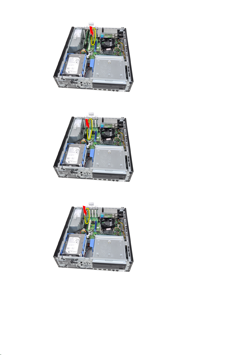
4. Remove the data cable and power cable from the back of the optical drive.
5
5. Slide up the optical-drive latch and then push the optical drive from the back
towards the front of the computer.
21

Installing The Optical Drive
1. Slide down the optical-drive latch and push the optical drive from the front towards
the back of the computer.
2. Connect the data cable and power cable to the optical drive.
3. Install the front bezel.
4. Install the cover.
5. Follow the procedures in After Working Inside Your Computer.
22

Hard Drive
Removing the Hard Drive
1. Follow the procedures in Before Working Inside Your Computer.
2. Remove the cover.
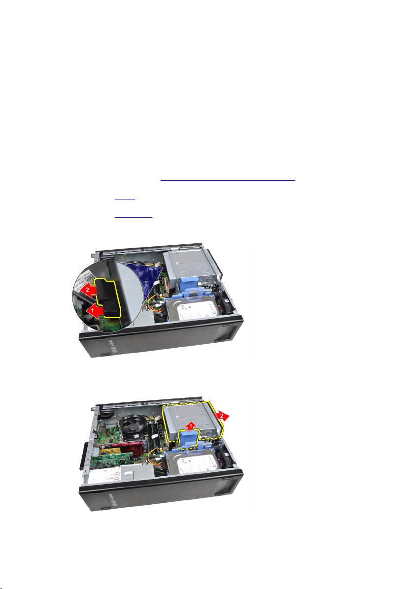
3. Remove the data cable and power cable from the back of the hard drive.
4. Press the hard-drive bracket latch towards the hard drive and lift it upward.
6
5. Flex the hard-drive bracket and then remove the single 3.5 inch hard drive or two 2.5
inch hard drives from the bracket.
23
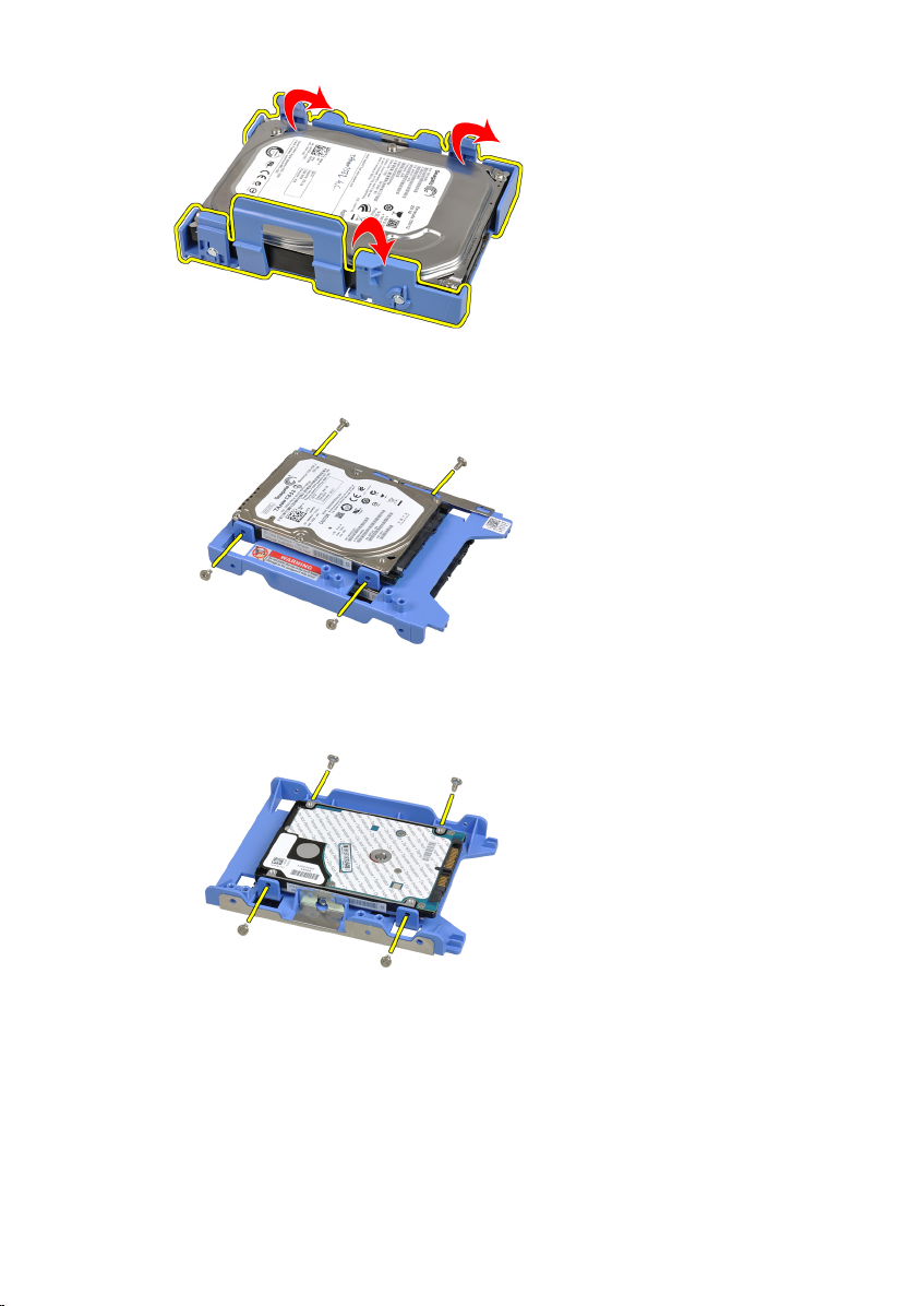
6. Turn over the hard-drive bracket and release the screws that secure the 2.5 inch
hard drive to the underside of the bracket.
7. Flex the hard-drive bracket and then remove the two 2.5 inch hard drives from the
bracket.
8. Release the screws that secure the 2.5 inch hard drive to the top of the hard-drive
bracket.
24

9. Release the screws that secure the 2.5 inch hard drive to the underside of the hard
drive bracket.
Installing The Hard Drive
1. Tighten the screws to secure the 2.5 inch hard drive(s) to the hard-drive bracket.
2. Flex the hard-drive bracket and then insert the single 3.5 inch hard drive or the two
2.5 inch hard drives into the bracket.
3. Press the hard-drive bracket latch towards the hard drive and insert it into the
chassis.
4. Connect the data cable and power cable to the back of the hard drive(s).
5. Install the cover.
6. Follow the procedures in After Working Inside Your Computer.
25

26
Memory
Removing the Memory
1. Follow the procedures in Before Working Inside Your Computer.
2. Remove the cover.
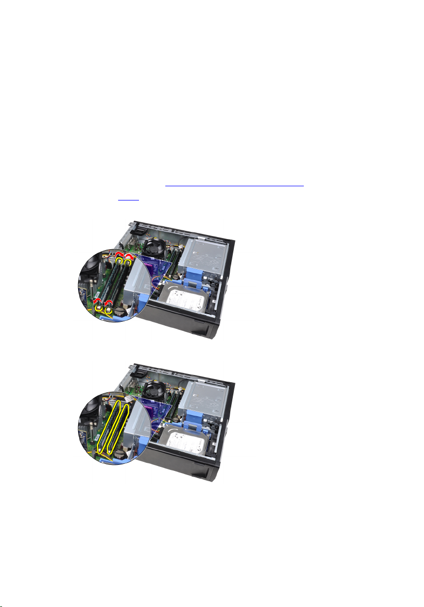
3. Release the memory-retention clips on each side of the memory modules.
4. Lift the memory modules out of the connectors on the system board.
7
27

Installing The Memory
1. Insert the memory modules into the connectors on the system board. Install the
memory module in the order of A1 > B1 > A2 > B2.
2. Press down on the memory modules until the retention clips spring back to secure
them in place.
3. Install the cover.
4. Follow the procedures in After Working Inside Your Computer.
28
8
Chassis Intrusion Switch
Removing the Chassis Intrusion Switch
1. Follow the procedures in Before Working Inside Your Computer.
2. Remove the cover.
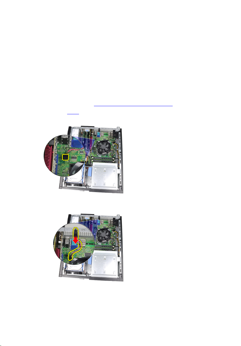
3. Disconnect the intrusion-switch cable from the system board.
4. Slide the intrusion switch toward the chassis bottom and remove it from the system
board.
29

Installing The Chassis Intrusion Switch
1. Insert the intrusion switch into the chassis rear and slide it toward the chassis top
to secure it.
2. Connect the intrusion-switch cable to the system board.
3. Install the cover.
4. Follow the procedures in After Working Inside Your Computer.
30
 Loading...