

Dell Networking S5000 Installation Manual

Dell Networking S5000
Installation Guide

Notes, Cautions, and Warnings
NOTE: A NOTE indicates important information that helps you make better use of your computer.
CAUTION: A CAUTION indicates either potential damage to hardware or loss of data and tells you how to avoid the
problem.
WARNING: A WARNING indicates a potential for property damage, personal injury, or death.
© 2013 Dell Inc.
Trademarks used in this text:
Dell
™
, the Dell logo,
Dell Boomi
™
,
Dell Precision
™
,
OptiPlex
™
,
Latitude
™
,
PowerEdge
™
,
PowerVault
™
,
PowerConnect
™
,
OpenManage
™
,
EqualLogic
™
,
Compellent
™
,
KACE
™
,
FlexAddress
™
,
Force10
™
and
Vostro
™
are trademarks of Dell
Inc.
Intel
®
,
Pentium
®
,
Xeon
®
,
Core
®
and
Celeron
®
are registered trademarks of Intel Corporation in the U.S. and other countries.
AMD
®
is a registered trademark and
AMD Opteron
™
,
AMD Phenom
™
and
AMD Sempron
™
are trademarks of Advanced Micro Devices, Inc.
Microsoft
®
,
Windows
®
,
Windows Server
®
,
Internet Explorer
®
,
MS-DOS
®
,
Windows Vista
®
and
Active Directory
®
are either trademarks
or registered trademarks of Microsoft Corporation in the United States and/or other countries.
Red Hat
®
and
Red Hat
®
Enterprise Linux
®
are registered trademarks of Red Hat, Inc. in the United States and/or other countries.
Novell
®
and
SUSE
®
are
registered trademarks of Novell Inc. in the United States and other countries.
Oracle
®
is a registered trademark of Oracle Corporation
and/or its affiliates.
Citrix
®
,
Xen
®
,
XenServer
®
and
XenMotion
®
are either registered trademarks or trademarks of Citrix Systems, Inc. in
the United States and/or other countries.
VMware
®
,
vMotion
®
,
vCenter
®
,
vCenter SRM
™
and
vSphere
®
are registered trademarks or
trademarks of VMware, Inc. in the United States or other countries.
IBM
®
is a registered trademark of International Business Machines
Corporation.
2013
Rev. A0X

Contents
1 About this Guide.......................................................................................................................... 5
Related Publications.................................................................................................................................................5
2 Introduction..................................................................................................................................7
Product Description..................................................................................................................................................7
3 Unpacking the Switch................................................................................................................ 9
Important Points Before You Continue..................................................................................................................... 9
Hardware Installation Overview.............................................................................................................................10
4 Hardware Overview..................................................................................................................11
I/O Panel................................................................................................................................................................. 11
Utility Panel.............................................................................................................................................................12
Power Supplies................................................................................................................................................ 12
Fans.................................................................................................................................................................. 12
Port Numbering Convention................................................................................................................................... 13
System Status.........................................................................................................................................................13
5 Site Preparations.......................................................................................................................19
Site Selection..........................................................................................................................................................19
Cabinet Placement..................................................................................................................................................19
Storing Components............................................................................................................................................... 20
6 Installation..................................................................................................................................21
Before You Begin....................................................................................................................................................21
Install the S5000 Chassis in a Rack or Cabinet....................................................................................................... 22
To install the S5000 system, Dell Networking recommends completing the installation procedures in
the order presented here................................................................................................................................. 22
Attaching the Mounting Brackets.......................................................................................................................... 22
Rack Mounting Safety Considerations................................................................................................................... 23
Installing the S5000 Chassis into a 4-Post Rack or Cabinet....................................................................................24
Rack Grounding...................................................................................................................................................... 24
Important Points to Remember for Installing an Ethernet Module.........................................................................24
Installing an Ethernet Module.................................................................................................................................25
Replacing an Ethernet Module............................................................................................................................... 26
Important Points to Remember for Installing a Fibre Channel Module.................................................................. 26
Installing a Fibre Channel Module..........................................................................................................................27
Replacing a Fibre-Channel Module........................................................................................................................ 28

Important Points to Remember for Installing an AC Power Supply........................................................................28
Installing an AC Power Supply............................................................................................................................... 29
Important Points to Remember for Installing a DC Power Supply..........................................................................30
Assembling and Connecting the Safety Ground Wire for DC Power Supply..........................................................31
Installing a DC Power Supply................................................................................................................................. 32
Installing the Ferrite Bead for DC Power and Return Cables................................................................................. 34
Securing Power Cables.......................................................................................................................................... 35
Replacing an AC or DC Power Supply.................................................................................................................... 36
Important Points to Remember for Installing a Fan Module...................................................................................36
Installing a Fan Module.......................................................................................................................................... 37
Replacing a Fan Module......................................................................................................................................... 37
Installing the SFP+ and QSFP+ Optics.................................................................................................................... 37
Splitting QSFP+ Ports to SFP+ Ports.......................................................................................................................38
Important Points to Remember........................................................................................................................ 38
Connecting the Stacking Ports (Optional).............................................................................................................. 38
Connecting Two S5000 Systems.............................................................................................................................40
Connecting Three S5000 Systems.......................................................................................................................... 40
Supplying Power and Powering Up the System.....................................................................................................41
AC Power..........................................................................................................................................................42
DC Power..........................................................................................................................................................42
Hot-Swapping Units in a Stack...............................................................................................................................42
7 Technical Specifications......................................................................................................... 43
8 Agency Compliance..................................................................................................................45
USA Federal Communications Commission (FCC) Statement.................................................................................45
Canadian Department of Communication Statement............................................................................................. 45
European Union EMC Directive Conformance Statement......................................................................................45
European Community Contact..........................................................................................................................46
Japan: VCCI Compliance for Class A Equipment....................................................................................................46
Korean Certification of Compliance........................................................................................................................46
Safety Standards and Compliance Agency Certifications..................................................................................... 47
Electromagnetic Compatibility (EMC).....................................................................................................................47
Product Recycling and Disposal.............................................................................................................................48
9 Technical Support.....................................................................................................................49
The iSupport Website............................................................................................................................................. 49
Accessing iSupport Services................................................................................................................................. 49
Requesting a Hardware Replacement....................................................................................................................49
Contacting Technical Support................................................................................................................................50
1
About this Guide
This guide provides site preparation recommendations, and step-by-step procedures for rack mounting, installing and
replacing pluggable modules, and connecting to a power source.
After you have completed the hardware installation and power-up of the S5000, for software configuration information,
refer to the
FTOS Configuration Guide for the S5000 Switch
and for Command Line Interface (CLI) information, refer to the
FTOS Command Line Reference Guide for the S5000 Switch.
CAUTION: To avoid electrostatic discharge (ESD) damage, wear grounding wrist straps when handling this
equipment.
WARNING: Only trained and qualified personnel can install this equipment. Read this guide before you install and
power up this equipment. This equipment contains two power cords. Disconnect both power cords before
servicing.
WARNING: This equipment contains optical transceivers, which comply with the limits of Class 1 laser radiation.
WARNING: When no cable is connected, visible and invisible laser radiation may be emitted from the aperture of
the optical transceiver ports. Avoid exposure to laser radiation and do not stare into open apertures.
Related Publications
For more information about the S5000, refer to the following documents:
•
FTOS Configuration Guide for the S5000 Switch
•
FTOS Command Line Reference Guide for the S5000 Switch
•
FTOS Release Notes for the S5000 Switch
NOTE: For the most recent documentation and software, visit iSupport (registration for access to some sections is
required): http://www.dell.com/support/manuals.
5

6

2
Introduction
This document provides basic information about installing the S5000 switch.
For information about how to configure and monitor switch features, refer to the
FTOS Configuration Guide for the S5000
Switch
, which is available on the Dell Support website at http://support.dell.com/manuals.
This document contains the following sections:
• Product Description
• Unpacking the Switch
• Hardware Overview
• Site Preparations
• Installation
• Technical Specifications
• Agency Compliance
• Technical Support
Product Description
The S5000 is part of Dell Networking's S-Series switches for Data Center Top of Rack (ToR) switches.
The S5000 is purpose-built to provide architectural flexibility for unified and virtualized environments. It is a 10G ToR
solution that enables converged local area networks (LAN) and storage area networks (SAN) in the same box. The S5000
delivers Fibre Channel over Ethernet (FCoE) and Fibre Channel (FC) capability in a one rack unit (RU) ToR switch form
factor.
The S5000 supports Data Center Bridging (ETS/PFC/DCBX), FCoE Transit (FIP Snooping), NPIV Proxy Gateway (NPG), and
Internet small computer system interface (iSCSI) storage traffic. The S5000 also provides aggregation and convergence
functionality using pluggable modules for flexible configuration.
7

8

3
Unpacking the Switch
The S5000 and its accessories are shipped in multiple boxes. Before unpacking the switch, inspect the container and
immediately report any evidence of damage. Verify that you have received your ordered items. For example, if you order
one S5000 switch, the following items are included.
WARNING: If any item is missing or damaged, contact your Dell Networking representative or reseller for
instructions.
WARNING: Electrostatic discharge (ESD) damage can occur if components are mishandled. Always wear an ESDpreventive wrist or heel ground strap when handling the S5000 and its components.
• One S5000 switch
• Two Fans
• Two Power Supplies (either AC or DC)
• One rail kit (#1 and #2 Phillips screwdrivers required)
• Screws for rack installation
• Two to Four I/O Modules (according to order)
• Two Blanks
• One RJ-45 to DB-9 female cable
• Two AC or DC power cords for AC or DC units (country/region specific)
•
Getting Started Guide
•
Safety and Regulatory Information
•
Warranty and Support Information
•
Software License Agreement
1. Place the container on a clean, flat surface and cut all straps securing the container.
2. Open the container or remove the container top.
3. Carefully remove all components from the container and place it on a secure and clean surface.
4. Remove all packing material.
5. Inspect the switch and accessories for damage.
Important Points Before You Continue
• Identify the I/O and Utility panel on the chassis. The I/O panel has four fixed 40GbE ports on the right side of the
panel, refer to Figure 1. The Utility panel has the power supply slots, LEDs, and USB slots on the left side of the
panel, refer to Figure 3.
• Identify slots 0, 1, 2, and 3 on the I/O panel, refer to Figure 2. You can insert a Fibre Channel module only in slot 0.
You can install the Ethernet modules in slots 0, 1, 2, and 3.
• Identify slots 0, 1, 2, and 3 on the Utility panel, refer to Figure 3. You can insert Power supply units (PSUs) only in
slots 0 and 3. You can insert the Fan modules in any of the slots.
9
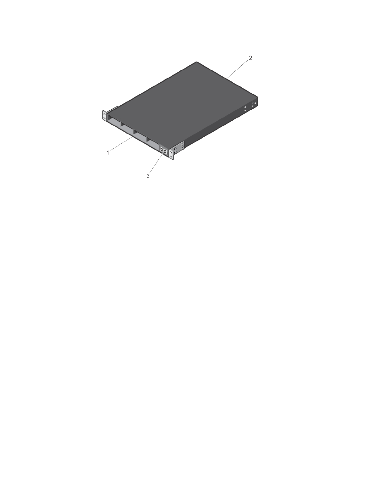
Figure 1. S5000 I/O and Utility Panels
1. I/O panel
2. Utility panel
3. Four 40GbE QSFP+ ports (each port ALSO supports 4 × 10GbE mode)
Hardware Installation Overview
To install the S5000, follow these steps:
1. Attach the mounting brackets.
2. Install the S5000 chassis into a 4–post rack or cabinet.
3. Ground the rack.
4. Install the Ethernet and/or Fibre Channel modules (Fibre Channel module must be installed only in slot 0).
5. Install the power supplies.
6. Secure the power cables.
7. Install the fan modules.
8. Install the SFP+ and QSFP+ optics.
9. Supply power and power up the system.
10

4
Hardware Overview
This section contains information about device characteristics and modular hardware configurations for the S5000.
The S5000 has the following physical dimensions:
• Height: 1.71 inches (43.5 mm)
• Width: 17.4 inches (441.9 mm)
• Depth: 28 inches (711.2 mm)
The S5000 has a chassis design with 640Gbps switching bandwidth.
The system also provides one DB9 RS-232 console port with YOST RJ-45 pinout and a dedicated Ethernet service port for
out-of-band (OOB) management functions.
I/O Panel
All fixed data ports (4 × 40GbE quad small form-factor pluggable plus [QSFP+] ports) and the four slots for pluggable
modules are on the I/O panel.
The I/O panel includes:
• Pluggable Modules
– 12-Port Ethernet Module (1G/10G speeds)
– 12-Port Fibre Channel Module (2G/4G/8G speeds)
• 4 × 40GbE QSFP+ Ports and light emitting diodes (LEDs)
Figure 2. S5000 I/O Panel
1. Slot 0 (supports Ethernet and Fibre Channel
modules)
2. Slot 1 (supports only Ethernet modules)
3. Slot 2 (supports only Ethernet modules)
4. Slot 3 (supports only Ethernet modules)
5. Four 40GbE QSFP+ ports (each port ALSO supports
4 × 10GbE mode)
NOTE
: The LED displays for the system status are on both sides of the chassis. The fan and power status LEDs are
on the Utility panel.
11

Utility Panel
The Utility panel side of the platform contains the fan and power modules.
Figure 3. S5000 Power Supplies and Fan Modules
1. Slot 0 (for PSU 0)
2. Slot 1 (for Fan Module 0)
3. Slot 2 (for Fan Module 1)
4. Slot 3 (for PSU 1)
5. Grab Handles
Power Supplies
The S5000 supports two hot-swappable PSUs.
NOTE: The PSUs must be installed at the customer site.
The S5000 has SKUs that support the following configurations:
• AC PSU with fan airflow from I/O to Utility
• AC-R PSU with fan airflow from Utility to I/O
• DC PSU with fan airflow from I/O to Utility
• DC-R PSU with fan airflow from Utility to I/O
PSUs are field replaceable. To ensure power redundancy and adequate cooling, install two power supplies in the
switch. When running with full redundancy (two PSUs installed and running), you can remove and replace one PSU
while the other PSU is running without disrupting traffic.
Fans
The S5000 supports two fan trays with airflow directions from I/O to Utility or Utility to I/O.
Do not mix I/O to Utility and Utility to I/O airflows in a single S5000 chassis. All fans and PSUs in a configuration must be
in the same airflow direction. If you create a mixed airflow configuration, the software notifies you of the invalid
configuration.
The fans must be installed at the customer site.
12
Port Numbering Convention
Even-numbered ports are at the bottom of the I/O panel and for modules odd-numbered ports are at the top of the I/O
panel.
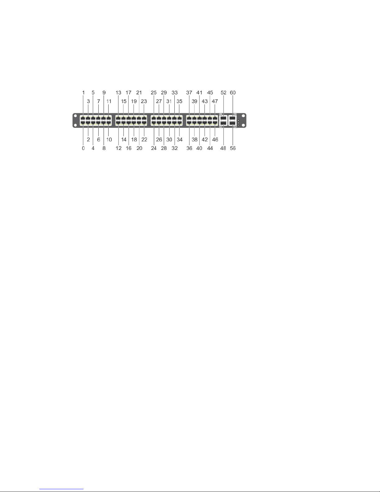
Figure 4. Port Numbering
The previous figure shows the fixed four 40GbE data ports (ports 48, 52, 56, and 60) and the four slots for pluggable
modules on the S5000 I/ O panel. You can also use the 40GbE ports in 4 × 10GbE mode.
The S5000 supports the following possible modules:
• 12-Port Ethernet Module (1G/10G speeds) (slot 0, 1, 2, or 3)
• 12-Port Fibre Channel Module (2G/4G/8G speeds) (slot 0)
The valid slot numbers are stack-unit numbers (from 0 to 11). The valid port numbers for each interface type are:
• 1GbE: Ports 0 to 47
• 10GbE: Ports 0 to 63
• 40GbE: Ports 48, 52, 56, and 60
• Fibre Channel: Ports 0 to 11
• Management: Port 0
System Status
You can view S5000 status information in several ways, including LEDs and through the CLI show commands and with
simple network management protocol (SNMP).
For more information about these options, refer to the
FTOS Command Line Reference Guide
and
FTOS Configuration
Guide for the S5000 Switch
.
As shown in the following figure, the S5000 includes LED displays on the I/O and Utility side of the chassis. When the
S5000 powers up or reloads, the status LED on the power supplies are solid green.
The following table lists the LED definitions for the S5000 system.
13
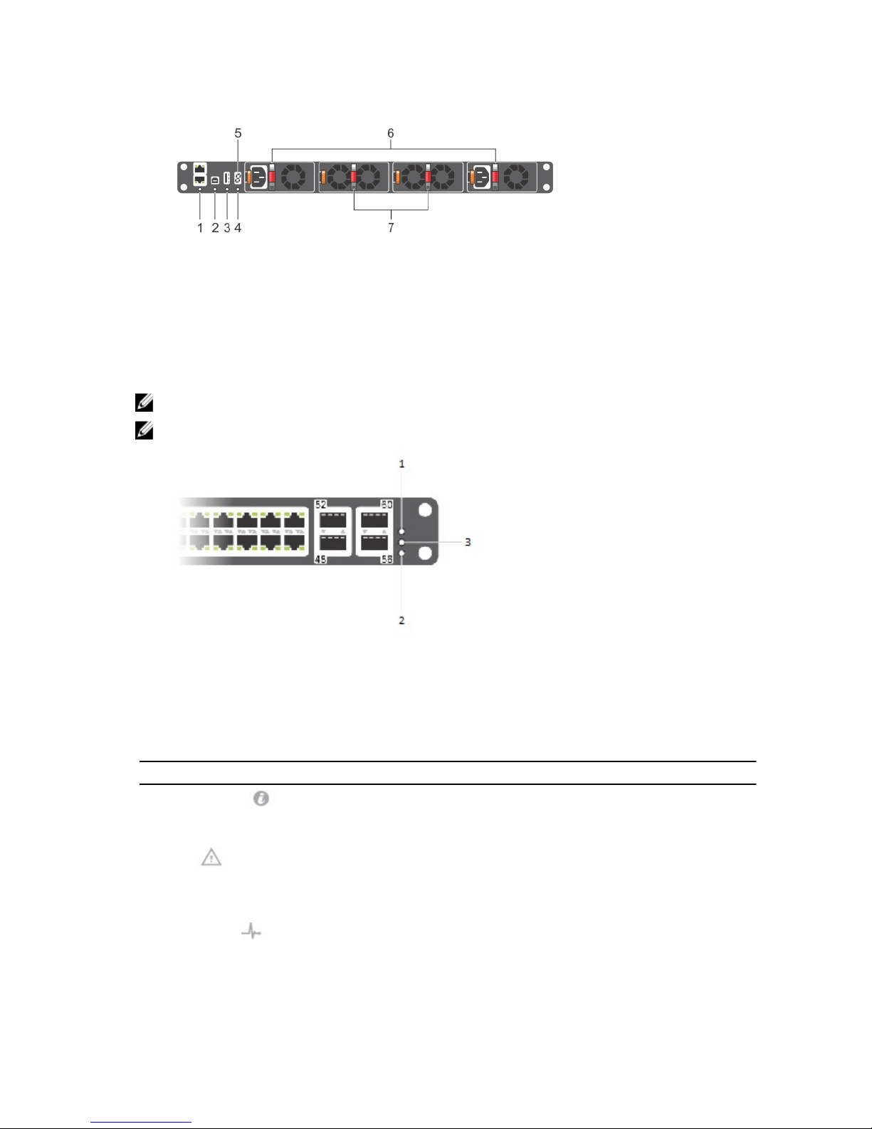
Figure 5. System LEDs (Utility Panel) (AC Power Supplies installed)
1. Locator beacon LED
2. Alarm LED
3. System status LED
4. Master LED
5. Seven–segment display to identify Stack ID
6. PSU status LED
7. Fan status LED
NOTE: For AC PSUs, an illuminated translucent handle indicates the power status.
NOTE: For DC PSUs, the power status LED is on the upper-left corner.
Figure 6. System LEDs (I/O Panel)
1. Locator beacon LED
2. Alarm LED
3. System status LED
Table 1. System LED Displays (Utility and I/O Panel)
Label LED Color/Display Description
Locator beacon LED
• Off
• Blue
• No activity
• System beacon/locator
Alarm LED
• Off
• Amber solid
• Red solid
• No alarm
• Minor alarm
• Critical alarm
System status LED
• Off
• Green solid
• No power
• Normal operation
14

Label LED Color/Display Description
• Green blinking
• Amber solid
• System is booting
• System in card problem state
Master LED
• Green solid
• Green blinking
• Off
• Switch in Stacking Master
mode OR Switch in
Standalone mode
• Switch in Stacking Standby
mode
• Switch in Stacking Member
mode
PSU status LED
• Green solid
• Off
• Normal operation
• Power not present
Fan status LED
• Green solid
• Off
• Normal operation
• Power not present
Figure 7. Module LEDs
1. Port locator beacon LED
2. Port link/activity LED
3. Module locator beacon LED
4. Module status LED
NOTE: The downward and upward pointing triangles denote the lower and upper port LEDs respectively.
Table 2. Ethernet Port/Module LEDs
Label LED Color/Display Description
Port locator beacon LED
• Off • No activity
15
 Loading...