

Dell Networking S4048 Installation Manual

Dell Networking S4048–Open Networking (ON)
Installation Guide
January 2017

Notes, Cautions, and Warnings
NOTE: A NOTE indicates important information that helps you make better use of your computer.
CAUTION: A CAUTION indicates either potential damage to hardware or loss of data and tells you how to avoid the problem.
WARNING: A WARNING indicates a potential for property damage, personal injury, or death.
Copyright © 2017 Dell Inc. or its subsidiaries. All rights reserved. Dell, EMC, and other trademarks are trademarks of Dell Inc. or its subsidiaries. Other
trademarks may be trademarks of their respective owners.
2017 - 01
Rev. A02

Contents
1 About this guide............................................................................................................................................. 5
Related documents............................................................................................................................................................5
2 The S4048–ON system................................................................................................................................. 6
Introduction.........................................................................................................................................................................6
Features...............................................................................................................................................................................7
Physical dimensions........................................................................................................................................................... 7
System status.....................................................................................................................................................................8
LED display..........................................................................................................................................................................8
LED behavior................................................................................................................................................................ 9
Prerequisites...................................................................................................................................................................... 10
S4048–ON congurations............................................................................................................................................... 11
3 Site preparations.......................................................................................................................................... 12
Site selection..................................................................................................................................................................... 12
Cabinet placement............................................................................................................................................................12
Rack mounting.................................................................................................................................................................. 13
System ground..................................................................................................................................................................13
Fans and airow................................................................................................................................................................13
Fan combinations........................................................................................................................................................13
Power.................................................................................................................................................................................13
Storing components.........................................................................................................................................................13
4 NEBS compliance.........................................................................................................................................15
Important information...................................................................................................................................................... 15
5 S4048–ON installation................................................................................................................................. 16
Unpack the S4048-ON system...................................................................................................................................... 16
Unpack.........................................................................................................................................................................16
Rack or cabinet hardware installation.............................................................................................................................17
Rack mount safety considerations............................................................................................................................17
ReadyRails system installation...................................................................................................................................17
Two-post ush-mount conguration........................................................................................................................18
Two-post center-mount conguration.....................................................................................................................19
Four-post threaded conguration............................................................................................................................20
S4048-ON installation................................................................................................................................................21
1U front-rack installation............................................................................................................................................ 21
Ground cable...............................................................................................................................................................23
SFP+ and QSFP+ optic installation................................................................................................................................23
QSFP+ optic replacement.........................................................................................................................................24
Split QSFP+ ports to SFP+ ports............................................................................................................................ 24
System power-up.............................................................................................................................................................24
Contents
3

Power up sequence................................................................................................................................................... 24
6 Power supplies.............................................................................................................................................25
Components..................................................................................................................................................................... 25
AC power supply installation...........................................................................................................................................26
AC power supply replacement..................................................................................................................................27
DC power supply installation...........................................................................................................................................27
DC power connections..............................................................................................................................................29
DC labels..................................................................................................................................................................... 30
7 Fans..............................................................................................................................................................31
Components......................................................................................................................................................................31
Fan module installation....................................................................................................................................................32
Fan module replacement.................................................................................................................................................32
After S4048–ON installation.......................................................................................................................................... 32
8 Management ports...................................................................................................................................... 33
RS-232 console port access...........................................................................................................................................33
Micro USB-B console port access.................................................................................................................................33
Mounting the USB Storage...................................................................................................................................... 34
Before you install an OS.................................................................................................................................................. 35
Example of the grub bootloaderExample of ONIE.................................................................................................35
ONIE Service Discovery on the S4048–ON System............................................................................................ 36
9 Specications.............................................................................................................................................. 37
Chassis physical design................................................................................................................................................... 37
IEEE standards................................................................................................................................................................. 38
Agency compliance..........................................................................................................................................................38
Network Equipment Building Systems (NEBS) Compliance................................................................................ 38
USA Federal Communications Commission (FCC) Statement............................................................................ 38
European Union EMC Directive Conformance Statement................................................................................... 39
Japan: VCCI Compliance for Class A Equipment...................................................................................................40
Korean Certication of Compliance.........................................................................................................................40
Safety Standards and Compliance Agency Certications..................................................................................... 41
Electromagnetic Compatibility (EMC)..................................................................................................................... 41
Product Recycling and Disposal............................................................................................................................... 42
10 Technical Support...................................................................................................................................... 43
The Dell Support Website............................................................................................................................................... 43
Accessing Support Services.....................................................................................................................................43
Contacting the Technical Assistance Center................................................................................................................43
Requesting a Hardware Replacement........................................................................................................................... 44
4
Contents
About this guide
This guide provides site preparation recommendations, step-by-step procedures for rack mounting and desk mounting, inserting optional
modules, and connecting to a power source.
CAUTION: To avoid electrostatic discharge (ESD) damage, wear grounding wrist straps when handling this equipment.
WARNING: Only trained and qualied personnel can install this equipment. Read this guide before you install and power up this
equipment. This equipment contains two power cords. Disconnect both power cords before servicing.
WARNING: This equipment contains optical transceivers, which comply with the limits of Class 1 laser radiation.
Figure 1. Class 1 laser product
NOTE
: When no cable is connected, visible and invisible laser radiation may be emitted from the aperture of the optical
transceiver ports. Avoid exposure to laser radiation and do not stare into open apertures.
Related documents
For more information about the S4048–ON system, see the following documents:
• Dell Networking S4048–Open Networking (ON) Getting Started Guide
• Dell Networking S4048–Open Networking (ON) Release Notes
• Dell Open Networking Troubleshooting Guide
NOTE
: For the most recent documentation, visit Dell Support: www.dell.com/support.
1
About this guide 5
The S4048–ON system
The following sections describe the Dell S4048–ON system:
Topics:
• Introduction
• Features
• Physical dimensions
• System status
• LED display
• Prerequisites
• S4048–ON congurations
Introduction
S4048-ON is a networking switch for campus aggregation and core switching 10 Gbps servers and 40 Gbps optical uplinks to the 40 Gbps
switching fabric in the core.
The S4048–ON has:
• Forty-eight ports of 10G SFP+ ports for a 1/10 Gbps transceiver
• Six 40 Gbps xed QSFP+ optical ports for a 40 Gbps transceiver
• Serial RS 232 port, RJ-45, and MicroUSB
• RJ–45 management port
The S4048–ON I/O side includes:
• Forty-eight xed SFP+ and six xed QSFP+ ports
• Management port
• USB 2.0 port
• Serial RS 232 port, RJ-45 and MicroUSB
• LED display for the system, fan, and power status
Figure 2. S4048–ON I/O-side view
2
6 The S4048–ON system
1 SFP+ ports
2 QSFP+ ports
3 USB Type-A storage port
4 MicroUSB console port
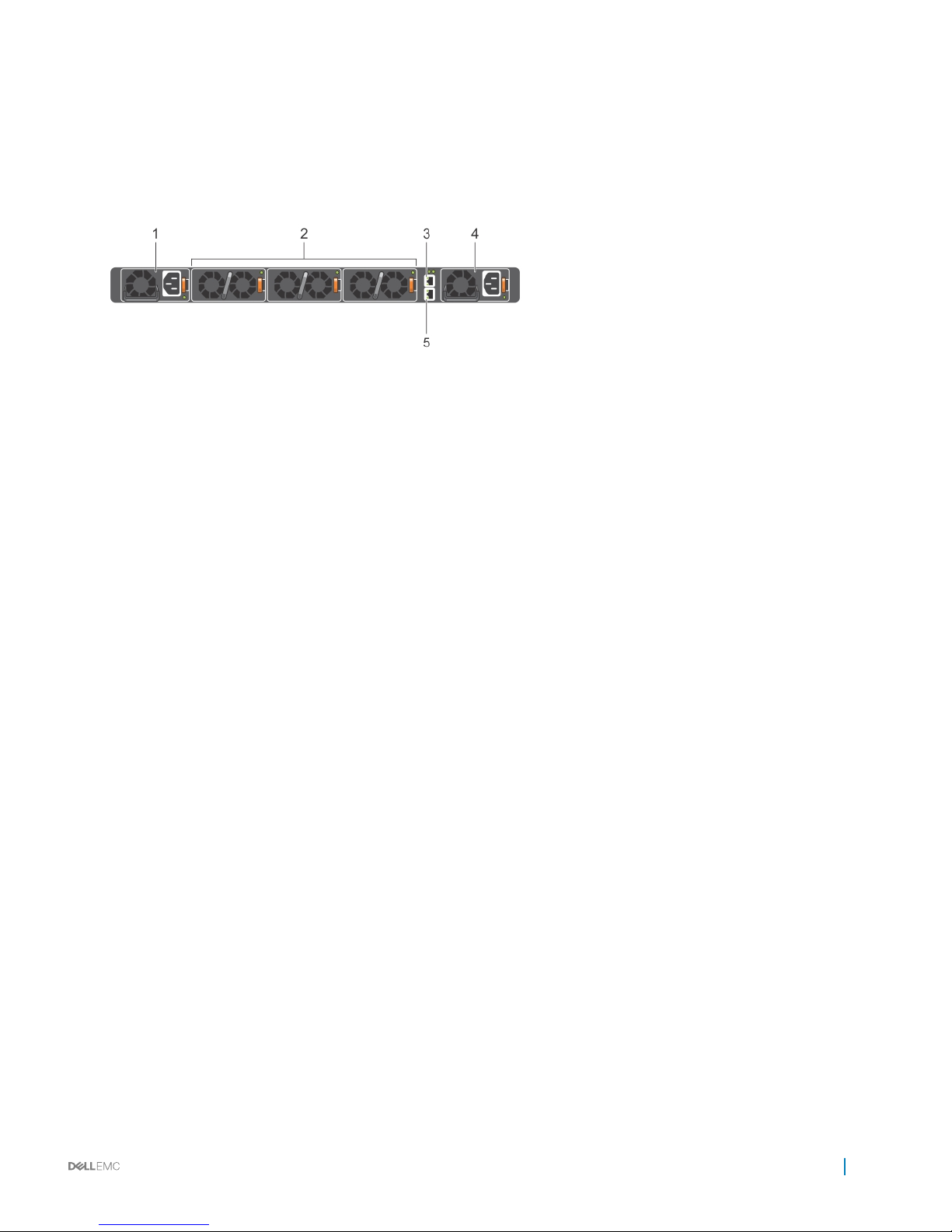
Figure 3. S4048–ON PSU-side view
1 Power supply unit 1
2 Fan module
3 Out-of-band management port
4 Power supply unit 2
5 RS-232 serial console port
Features
The S4048–ON oers the following features:
• Forty-eight xed 1/10 Gbps SFP+ ports
• Six xed 40 Gbps QSFP+ ports for 40 Gbps transceivers
• One Micro USB serial console port
• One universal serial bus (USB) Type-A port for more le storage
• Rangeley Central processing unit (CPU) system with large memory with 2 GB DDR III RAM
• Temperature monitoring
• Software-readable thermal monitor
• Real time clock (RTC) support
• Hot-plug redundant power supply
• Power management monitoring
• Removable fans
• Standard 1U chassis
Physical dimensions
The S4048-ON has the following physical dimensions:
• 440 x 460 x 44 mm (W x D x H)
• 17.32 x 18.11 x 1.73 inches (W x D x H)
The S4048–ON system
7
System status
You can view S4048–ON status information using the light emitting diodes (LEDs).
LED display
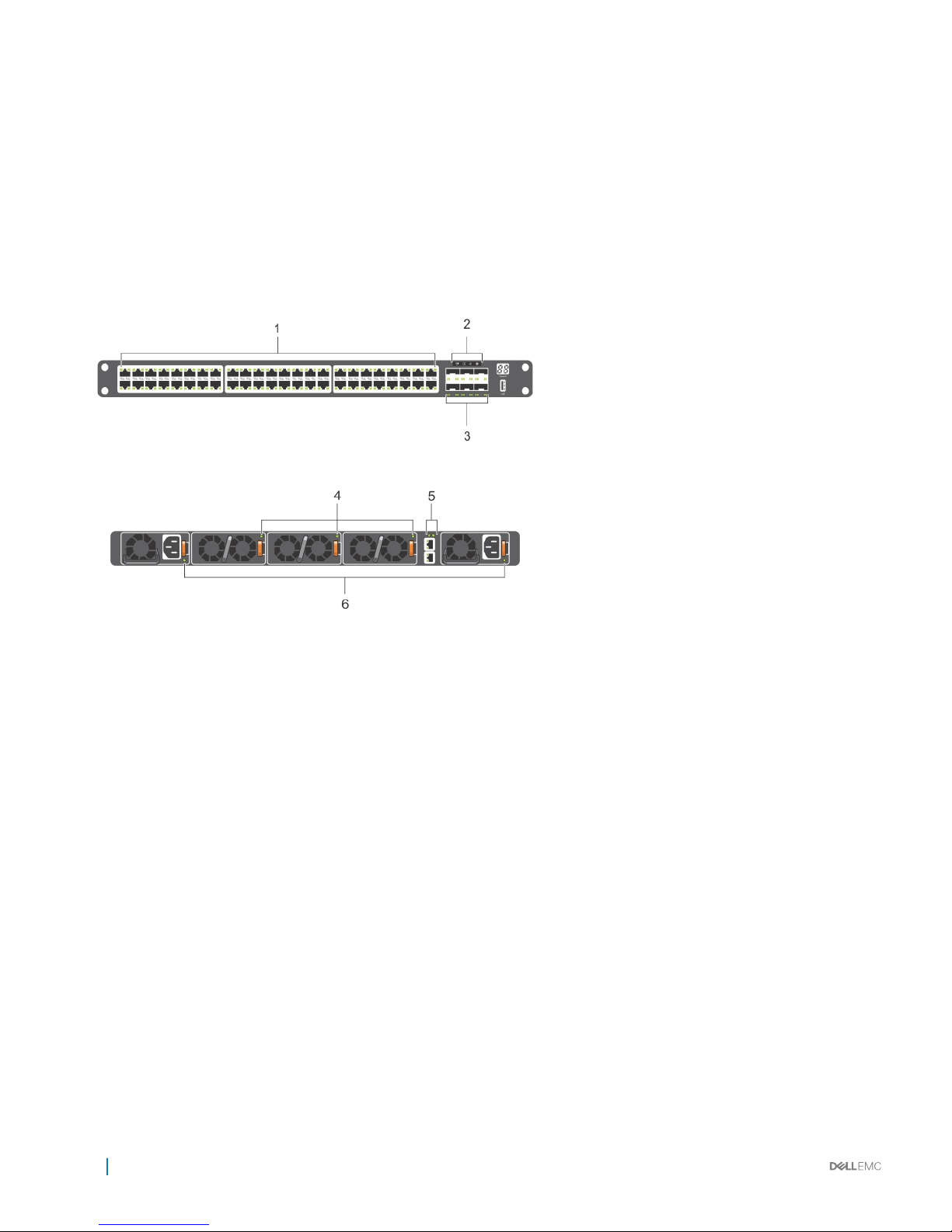
The S4048–ON includes LED displays on both the I/O Port and PSU side of the chassis, as shown.
For LED information, see your third-party operating software documentation.
Figure 4. S4048–ON LEDs
1 SFP+ port Link and activity LEDs
2 System LEDs
3 QSFP+ port LEDs
4 FAN LED
5 Management port LEDs
6 PSU LED
8
The S4048–ON system
LED behavior
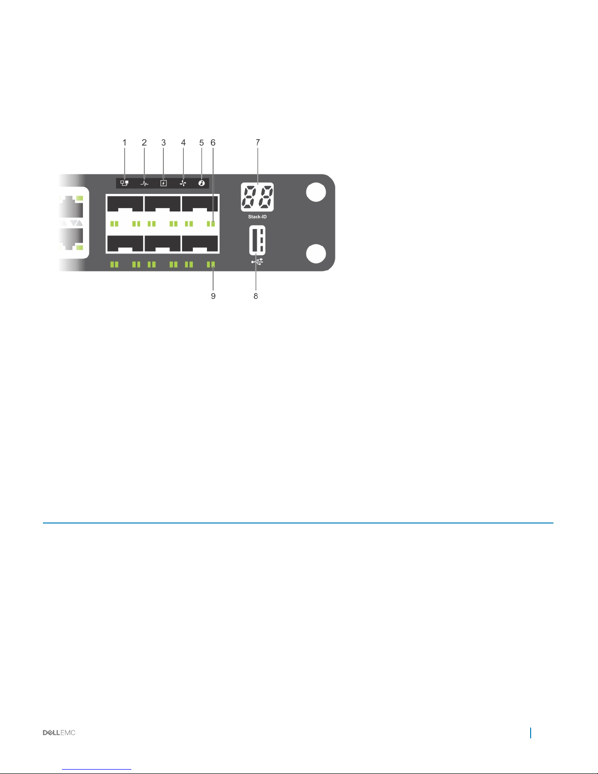
The following S4048–ON system LED behavior is seen during open networking installation environment (ONIE) operations:
Figure 5. S4048–ON LEDs
1 Master LED
2 System LED
3 Power LED
4 Fan LED
5 Locator LED
6 SFP+ link/activity LEDs
7 Stack LED
8 USB port LED
9 QSFP+ link/activity LEDs
Table 1. S4048–ON LED behavior
LED Description
System Status/Health LED
• Solid green—Normal operation
• Blinking green—Booting
• Solid amber—Critical system error
• Blinking amber—Non-critical system error, fan failure, or power
supply failure
Power LED
• O—No power
• Solid Green—Normal
• Solid amber—POST is in process
• Blinking amber—Power supply failed
MASTER LED
• O—Switch is in Stacking Slave mode
• Solid green—System is in Stacking Master or Standalone mode
The S4048–ON system 9

LED Description
FAN LED
• Solid green—fan powered and running at the expected RPM
• Solid amber—fan failed including incompatible airow direction
when you insert the PSU or fan trays with diering airows
PSU LED
• Solid green—Normal operation
• Solid amber—Power supply critical event causing a shutdown
• Blinking amber—Power supply warning event; power continues
to operate.
LOCATOR LED
• O—Locator function is disabled
• Blinking blue—Locator function is enabled
Table 2. Management Ethernet port LEDs
LED Description
Link LED
• O—No Link
• Solid green—Link on 1 Gbps speed
• Solid yellow—Link on 10/100 Mbps speeds
Table 3. SFP+ port LEDs
LED Description
Link LED
• O—No Link
• Solid green—Link on 10 Gbps speed
• Solid Amber—Link on 1 Gbp speed
NOTE: If you are using 1x40G, one LED displays. If you are
using 4x10G, four LEDs display.
Activity LED
• O—No Link
• Blinking green—Transmit/receive is active
Table 4. QSFP+ port LEDs
LED Description
Link LED
• O—No Link
• Solid green—Link on 40 Gbps speed
• Solid amber—Link on 10 Gbps speeds
Prerequisites
The following is a list of components required for successful installation of the S4048-ON.
NOTE
: Detailed installation instructions for the S4048-ON are provided in Site Preparations and Install the S4048–ON.
• S4048–ON chassis or multiple chassis, if stacking
• AC country- and regional-specic cables to connect the AC power source to each of the chassis’ AC power supplies
10
The S4048–ON system

• Mounting brackets for rack installation, included
• Screws for rack installation
• #1 and #2 Phillips screwdrivers, not included
• Torx screwdriver, not included
• Ground cable screws, included
• Copper/ber cables
Other optional components are:
• Ground cable
• Additional power supply unit
• Additional fan module
• Additional mounting brackets if installing in a four-post rack or cabinet
S4048–ON congurations
You can order the S4048–ON system in several dierent congurations. You can also order optional modules and optics separately.
You can order the following supported hardware components:
• S4048–ON AC Normal Airow: 48 port 10 G RJ-45 ports with six QSFP+ 40 G ports, one AC power supply and three fan subsystems.
Airow is from the I/O-side to the PSU-side.
• S4048–ON AC Reverse Airow: 48 port 10 G RJ-45 ports with six QSFP+ 40 G ports, one AC power supply and three fan subsystems.
Airow is from the PSU-side to the I/O-side
• Fan with airow from the I/O-side to the PSU-side
• Fan with airow from the PSU-side to the I/O-side
• AC Power supply with airow from the I/O-side to the PSU-side
• AC Power supply with airow from the PSU-side to the I/O-side
The S4048–ON system
11

Site preparations
The S4048–ON is suitable for installation as part of a common bond network (CBN).
You can install the system in:
• Network telecommunication facilities
• Data centers
• Other locations where the National Electric Code (NEC) applies
For more information about S4048–ON specications, see Specications.
NOTE: Install the S4048–ON system into a rack or cabinet before installing any optional components.
Topics:
• Site selection
• Cabinet placement
• Rack mounting
• System ground
• Fans and airow
• Power
• Storing components
Site selection
Install Dell equipment in restricted access areas.
A restricted access area is one in which service personnel can only gain access using a special tool, lock, key or other means of security and
access is controlled by the authority responsible for the location.
Ensure that the area where you install your S4048–ON system meets the following safety requirements:
• Near an adequate power source. Connect the system to the appropriate branch circuit protection as dened by your local electrical
codes.
• Environmental temperature between 32° to 113°F (from 0° to 45°C).
• The switch operating ambient temperature range is from 10° to 35°C (from 50° to 95°F).
• Operating humidity is from 5 to 85 percent non-condensing.
• Storage humidity is from 5 to 95 percent non-condensing.
• In a dry, clean, well-ventilated and temperature-controlled room, away from heat sources such as hot air vents or direct sunlight.
• Away from sources of severe electromagnetic noise.
• Positioned in a rack or cabinet, or on a desktop with adequate space in the front, rear, and sides of the S4048–ON for proper
ventilation and access.
Cabinet placement
Install the S4048–ON only in indoor cabinets designed for use in a controlled environment.
Do not install the S4048–ON in outside cabinets. For cabinet placement requirements, see Site Selection.
3
12 Site preparations

The cabinet must meet minimum size requirements. Airow must be in accordance with the Electronic Industries Alliance (EIA) standard.
Ensure that there is a minimum of 5 inches (12.7 cm) between the intake and exhaust vents and the cabinet wall.
Rack mounting
When you prepare your equipment rack, ensure that the rack is grounded.
Ground the equipment rack to the same ground point the power service in your area uses. The ground path must be permanent.
System ground
Dell recommends you ground you system. Use the S4048–ON in a common bond network (CBN).
Connect the grounding cables as described in Install the S4048–ON.
Fans and airow
The S4048–ON fans support two airow options.
Fan combinations
The S4048-ON has stock keeping units (SKUs) that support the following congurations. Installation of the fans is done as part of the
factory install based on SKU type.
• AC PSU with fan airow from the I/O-side to the PSU-side
• AC PSU with fan airow from the PSU-side to the I/O-side
Be sure to order the fans suitable to support your site’s ventilation. Use a single type of airow fan in your system. Do not mix reverse and
normal air ows in a single S4048–ON chassis.
For proper ventilation, position the S4048-ON in an equipment rack (or cabinet) with a minimum of 5 inches (12.7 cm) of clearance around
the exhaust vents. When you install two S4048-ON systems near each other, position the two chassis at least 5 inches (12.7 cm) apart to
permit proper airow. The fan speed increases when the internal temperature reaches 161.6°F (72°C) and decreases to normal speed
when the temperature falls to 136.4°F (58°C). The S4048-ON never intentionally turns o the fans.
Power
To connect the chassis to the applicable power source, use the appropriate power cord with the S4048–ON. An AC power cord is included
with the system.
When installing AC systems, follow the requirements of the National Electrical Code, ANSI/NFPA 70 where applicable.
The system is powered-up when the power cord is connected between the system and the power source.
CAUTION
: Always disconnect the power cable before you service the power supply slots.
CAUTION: Use the power supply cord as the main disconnect device on the AC system. Ensure that the socket-outlet is located/
installed near the equipment and is easily accessible.
Storing components
If you do not install your S4048–ON and components immediately, Dell recommends properly storing the system and all optional
components by following these guidelines.
• Storage location temperature must remain constant ranging from -40° to 158°F (from -40°C to 70°C).
Site preparations
13

• Store on a dry surface or oor, away from direct sunlight, heat, and air conditioning ducts.
• Store in a dust-free environment.
NOTE: ESD damage can occur when components are mishandled. Always wear an ESD-preventive wrist or heel ground strap
when handling the S4048–ON and its accessories. After you remove the original packaging, place the S4048–ON and its
components on an anti-static surface.
14 Site preparations
 Loading...