

Page 1

Dell Networking
N1108T-ON/N1108P-ON/
N1108EP-ON/N1124T-ON/
N1124P-ON/N1148T-ON/
N1148P-ON Switches
Getting Started Guide
Guide de mise en route
Handbuch zum Einstieg
Руководство по началу работы
Priručnik za početak rada
Guía de introducción
Başlangıç Kılavuzu
הדובע תליחת ךירדמ
Regulatory Model: E17W and E18W
Regulatory Type: E17W001/E18W001/E18W002
Page 2

Dell Networking
N1108T-ON/N1108P-ON/
N1108EP-ON/N1124T-ON/
N1124P-ON/N1148T-ON/
N1148P-ON Switches
Getting Started Guide
Regulatory Models: E17W and E18W
Page 3
Notes, Cautions, and Warnings
NOTE: A NOTE indicates important information that helps you make better use of
your switch.
CAUTION: A CAUTION indicates either potential damage to hardware or loss of
data and tells you how to avoid the problem.
WARNING: A WARNING indicates a potential for property damage, personal
injury, or death.
Lithium battery caution:
• There is a danger of explosion if a battery is incorrectly replaced. Replace
only with the same or equivalent type. Dispose batteries of according to
the manufacturer's instructions.
• Disposing a battery into fire, a hot oven, mechanically crushing, or cutting
it can result in an explosion.
• Leaving a battery in an extremely hot environment can result in leakage of
flammable liquid, gas, or an explosion.
• If a battery is subjected to extremely low air pressure, it may result in
leakage of flammable liquid, gas, or an explosion.
• The device can only be used in a fixed location such as a lab or a machine
room. When you install the device, ensure that the protective earthing
connection of the socket-outlet is verified by a skilled person.
___________________
© 2019 Dell Inc. or its subsidiaries. All rights reserved. This product is protected by U.S. and
international copyright and intellectual property laws. Dell and the Dell logo are trademarks of
Dell Inc. in the United States and/or other jurisdictions. All other marks and names mentioned herein
may be trademarks of their respective companies.
Regulatory Models: E17W and E18W
May 2019 P/N Y7208 Rev. A01
Page 4

Contents
1 Introduction . . . . . . . . . . . . . . . . . . . . . . . . 5
N1100-ON Series Hardware Overview . . . . . . . . . . 5
Power Consumption for N1100-ON Series
PoE Switches
. . . . . . . . . . . . . . . . . . . . . 5
Ventilation System
N1100-ON Series Model Summary
. . . . . . . . . . . . . . . . . . 6
. . . . . . . . . . . . 7
2 N1108T-ON/N1108P-ON/N1108EP-ON
Installation
Mounting an N1108T-ON/N1108P-ON Switch Using
Dell Tandem Tray
Mounting an N1108T-ON/N1108P-ON/N1108EP-ON
on a Two-Post Rack Using Large L-brackets
Mounting all N11xx-ON Switches on a Wall
. . . . . . . . . . . . . . . . . . . . . . . . 8
. . . . . . . . . . . . . . . . . . . . . 8
. . . . . . . 9
. . . . . . 10
3 N1124T-ON/N1124P-ON/N1148T-ON/
N1148P-ON Installation
Rack Mounting an N1124T-ON/N1124P-ON/
N1148T-ON/ N1148P-ON Switch
Installing in a Rack
Installing as a Free-standing Switch
Stacking Multiple N1124T-ON/N1124P-ON/
N1148T-ON/ N1148P-ON Switches
. . . . . . . . . . . . . . . . . 13
. . . . . . . . . . . . . . 13
. . . . . . . . . . . . . 13
. . . . . . . . 14
. . . . . . . . . . . 14
Contents 3
Page 5

4 Starting and Configuring the
N1100-ON Series Switch
Connecting an N1100-ON Series Switch to
a Terminal
Connecting an N1100-ON Series Switch to
a Power Source
AC and DC Power Connection
Booting the N1100-ON Series Switch
Performing the N1100-ON Series
Initial Configuration
Enabling Remote Management
Initial Configuration Procedure
Example Session
Dell Easy Setup Wizard Console Example
. . . . . . . . . . . . . . . . . . . . . . . . 16
. . . . . . . . . . . . . . . . . . . . . 17
. . . . . . . . . . . . . . . . . . . 19
. . . . . . . . . . . . . . . . . . 21
. . . . . . . . . . . . . 15
. . . . . . . . . . . 17
. . . . . . . . . . 18
. . . . . . . . . . . 19
. . . . . . . . . . . 20
. . . . . 22
Next Steps
. . . . . . . . . . . . . . . . . . . . . 26
5 Agency compliance . . . . . . . . . . . . . . . . 28
4 Contents
Page 6

Introduction
This document provides basic information about the Dell Networking
N1100-ON Series switches, including how to install a switch and perform the
initial configuration. For information about how to configure and monitor
switch features, refer to the User Configuration Guide, which is available on
the Dell Support website at dell.com/support. See the Support website for
the latest updates on documentation and firmware.
NOTE: Switch administrators are strongly advised to maintain Dell Networking
switches on the latest version of the Dell Networking Operating System (DNOS).
Dell Networking continually improves the features and functions of DNOS based on
feedback from you, the customer. For critical infrastructure, pre-staging of the new
release into a non-critical portion of the network is recommended to verify network
configuration and operation with the new DNOS version.
N1100-ON Series Hardware Overview
This section contains information about device characteristics and modular
hardware configurations for the Dell Networking N1100-ON Series switch.
NOTE:
The N1108EP-ON switch uses an external power adaptor. There is no mounting kit
available for the N1108EP-ON external power adaptor. When installing the
N1108EP-ON, place the external power adaptor away from the switch.
Power Consumption for N1100-ON Series PoE Switches
Table 1-1 describes the power consumption for N1100-ON Series PoE
switches. The PoE power budget is 60W for the N1108P-ON, 123W for the
N1108EP-ON, 185W for the N1124P-ON, and 370W for the N1148P-ON.
Table 1-1. Power Consumption for N1100-ON Series PoE Switches
Model Input Voltage Power Supply
Configuration
N1108P-ON 100V/60Hz Main PSU 0.95A 88.64W
110V/60Hz Main PSU 0.87A 88.43W
Maximum Steady
Current
Consumption (A)
Maximum
Steady
Power (W)
120V/60Hz Main PSU 0.80A 88.22W
220V/50Hz Main PSU 0.49A 89.28W
240V/50Hz Main PSU 0.45A 89.70W
Getting Started Guide 5
Page 7

Model Input Voltage Power Supply
Configuration
Maximum Steady
Current
Consumption (A)
Maximum
Steady
Power (W)
N1108EP-ON 100V/60Hz 54VDC External
power adaptor
110V/60Hz 54VDC External
power adaptor
120V/60Hz 54VDC External
power adaptor
220V/50Hz 54VDC External
power adaptor
240V/50Hz 54VDC External
power adaptor
N1124P-ON 100V/60Hz Main PSU 2.66A 260.66W
110V/60Hz Main PSU 2.38A 257.95W
120V/60Hz Main PSU 2.16A 256.27W
220V/50Hz Main PSU 1.18A 250.52W
240V/50Hz Main PSU 1.10A 251.25W
1.62A 157W
1.47A 157W
1.35A 157W
0.74A 157W
0.67A 157W
N1148P-ON 100V/60Hz Main PSU 4.78A 476.03W
110V/60Hz Main PSU 4.32A 472.64W
120V/60Hz Main PSU 3.95A 470.58W
220V/50Hz Main PSU 2.14A 459.37W
240V/50Hz Main PSU 1.97A 459.06W
Ventilation System
One fan cools the N1108T-ON/N1108P-ON switches, and two fans cool the
N1024T-ON/N1024P-ON/N1048T-ON/N1048P-ON switches. The fans are
not field replaceable. The N1108EP-ON is a fanless switch.
6 Getting Started Guide
Page 8

N1100-ON Series Model Summary
Table 1-2. N1100-ON Series Switch Regulatory Numbers
Marketing
Model Name
(MMN)
N1108T-ON 10x1G/2x1G SFP Ports DPS-24GP E17W E17W001
N1108P-ON 10x1G/2x1G SFP/2xPoE+ Ports DPS-80AP/
N1108EP-ON 8x1G PoE+/2x1G PD/2x1G SFP
N1124T-ON 24x1G/4x10G SFP+ Ports DPS-40AP E18W E18W001
N1124P-ON 24x1G/4x10G SFP+/6xPoE+ Ports EDPS-250BF E18W E18W001
N1148T-ON 48x1G/4x10G SFP+ Ports DPS-60AP E18W E18W002
N1148P-ON 48x1G/4x10G SFP+/12xPoE+ Port YM-2501D E18W E18W002
Description Power Supply
Unit (PSU)
DPS-24GP
ADP-280BR E48W E48W001
Ports
Regulatory
Model Number
(RMN)
E17W E17W001
Regulatory
Type Number
(RTN)
Getting Started Guide 7
Page 9
N1108T-ON/N1108P-ON/N1108EP-ON
Installation
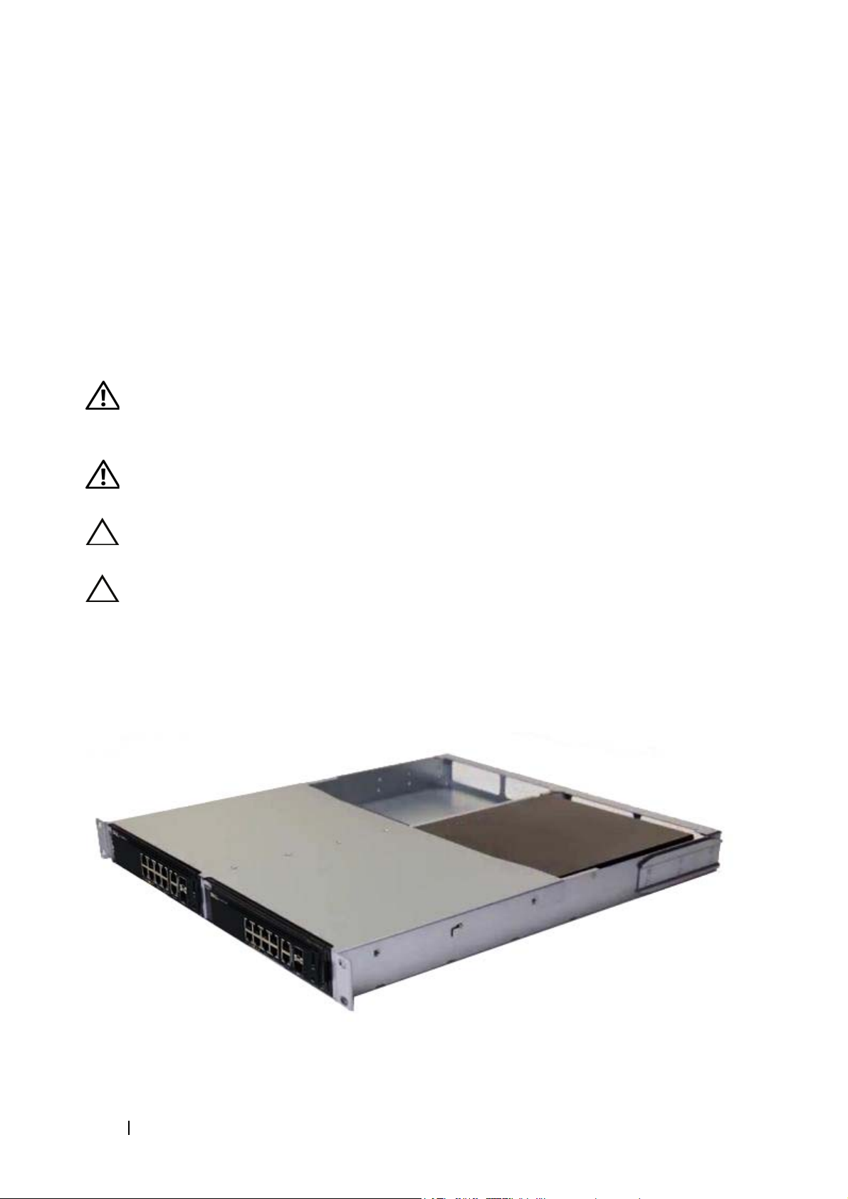
Mounting an N1108T-ON/N1108P-ON Switch
Using Dell Tandem Tray
The AC power connector is on the rear panel.
WARNING: Read the safety information in the
as well as the safety information for other switches that connect to or support the
switch.
WARNING: Do not use rack mounting kits to suspend the switch from under a
table or desk, or attach it to a wall.
CAUTION: Disconnect all cables from the switch before continuing. Remove all
self-adhesive pads from the underside of the switch, if they have been attached.
CAUTION: When mounting multiple switches into a rack, mount the switches
from the bottom up.
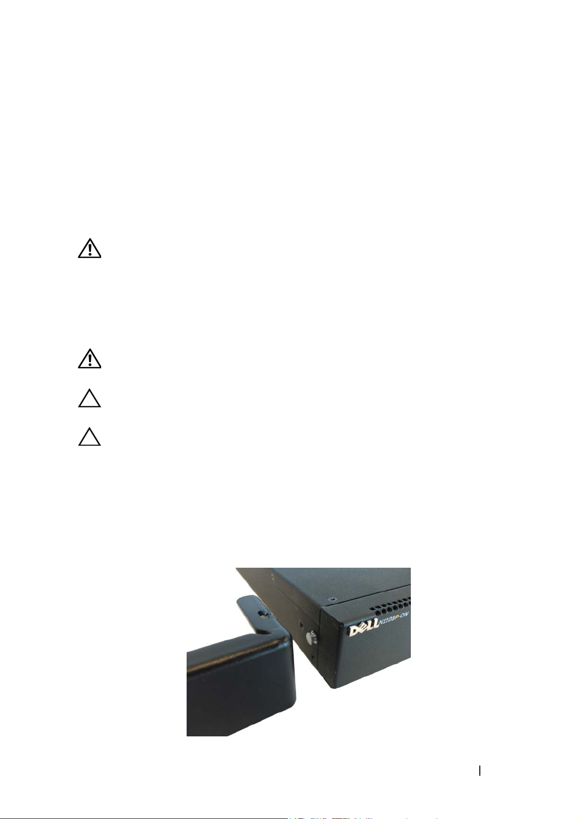
1
Secure the N1108T-ON/N1108P-ON switch in the Dell Tandem Tray Kit
as shown in Figure 1-1.
Figure 1-1. Dell Tandem Tray Kit
Safety and Regulatory Information
2
Insert the switch into the 48.26 cm (19 inch) rack, ensuring that the rack
mounting holes on the kit line up to the mounting holes in the rack.
8 Getting Started Guide
Page 10
3
Secure the kit to the rack with either the rack bolts or cage nuts and cagenut bolts with washers (depending on the kind of rack you have). Fasten
the bolts on the bottom before fastening the bolts on the top.
Mounting an N1108T-ON/N1108P-ON/N1108EPON on a Two-Post Rack Using Large L-brackets
NOTE: The AC power connector is on the rear panel of the N1108T-ON/N1108P-ON
switches. The DC power connector for the N1108EP-ON is at the center of the rear
panel.
NOTE: The N1108EP-ON switch uses an external power adaptor. There is no mounting kit
available for the N1108EP-ON external power adaptor. When installing the
N1108EP-ON, place the external power adaptor away from the switch.
CAUTION: As the N1108EP-ON is a fanless switch, do not place the external power
adaptor on top of the switch to avoid overheating.
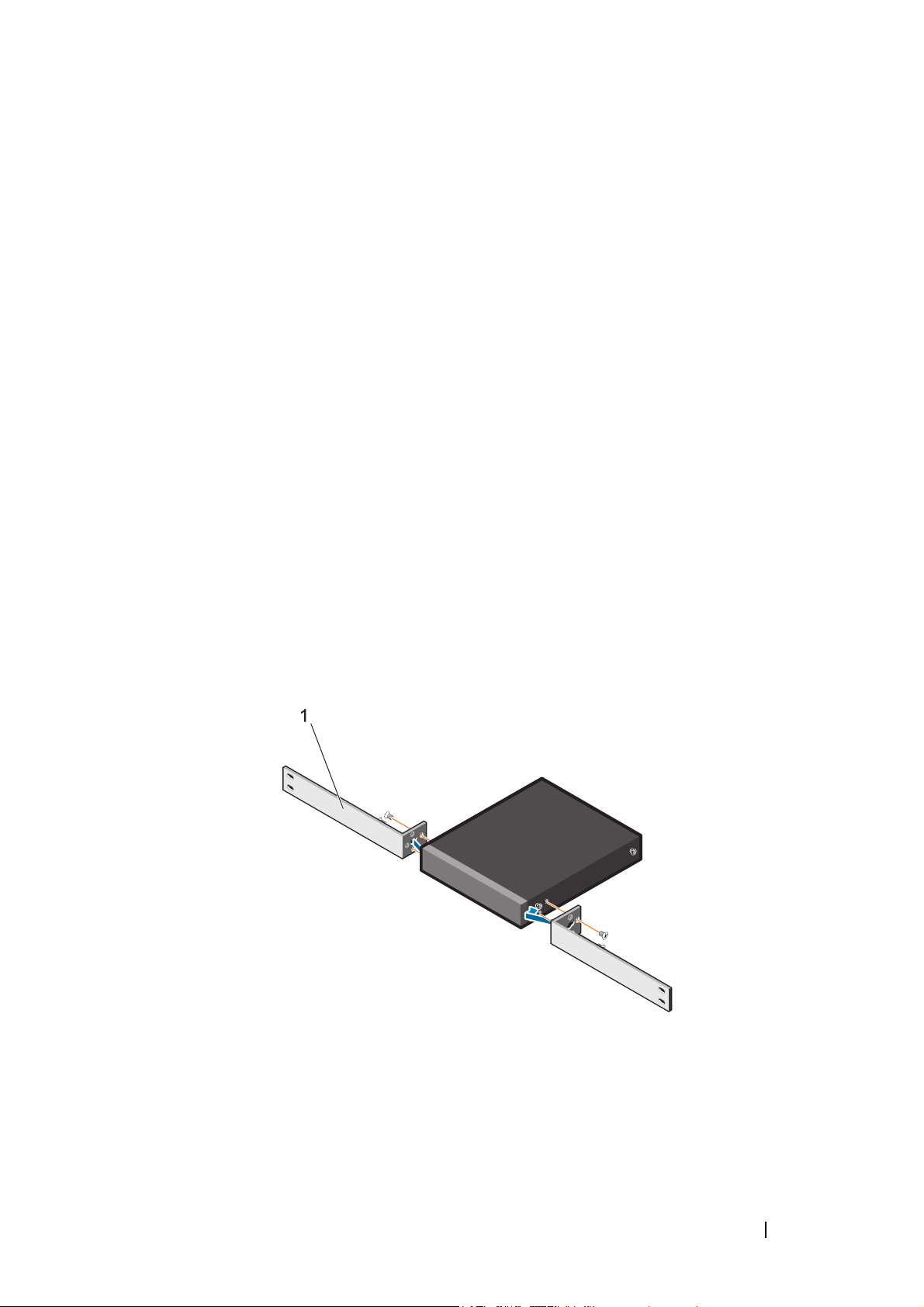
1
Place the supplied rack-mounting bracket on one side of the switch
making sure that the mounting holes on the switch line up to the
mounting holes on the rack mounting bracket. See item 1 in Figure 1-2.
Figure 1-2. Installing Using Large L-bracket Kit
2
Insert the supplied screws into the rack mounting holes and tighten with a
screwdriver.
3
Repeat the process on the other side of the switch.
Getting Started Guide 9
Page 11
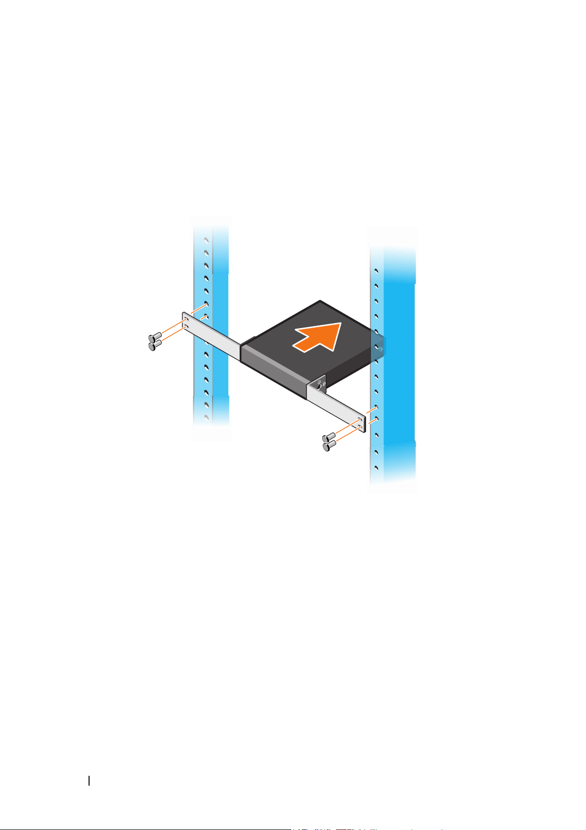
4
Insert the switch and rail assembly into the rack from the front of the rack.
Make sure that the rack-mounting holes on the switch line up to the
mounting holes on the rack.
5
Secure the switch to the rack with the rack screws. Fasten the lower pair of
screws before the upper pair of screws. See Figure 1-3.
Figure 1-3. Install on a Two-post Rack with L-Bracket
Mounting all N11xx-ON Switches on a Wall
1
Make sure that the mounting location meets the following requirements:
• The surface of the wall can support the switch.
• The location is ventilated to prevent heat buildup.
2
Place the supplied wall-mounting bracket on one side of the switch,
verifying that the mounting holes on the switch line up to the mounting
holes on the wall-mounting bracket.
3
Insert the supplied screws into the wall-mounting bracket holes and
tighten with a screwdriver. See Figure 1-4.
10 Getting Started Guide
Page 12
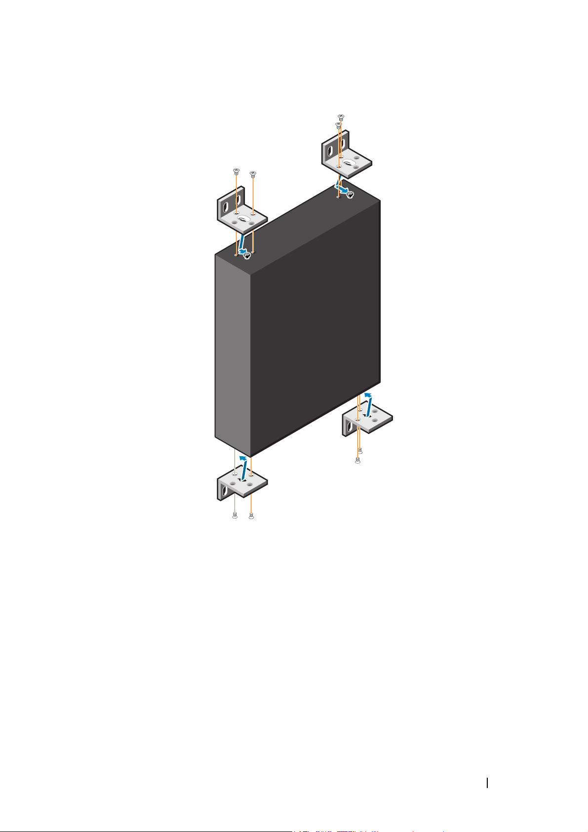
Figure 1-4. Inserting Mounting Brackets
4
Repeat the process for the wall-mounting bracket on the other side of the
switch.
5
Place the switch on the wall in the location where the switch is being
installed.
6
Mark the locations on the wall where the screws to hold the switch must be
prepared.
7
On the marked locations, drill the holes and place all the eight supplied
anchors in the holes.
8
Insert the supplied screws into the wall-mounting bracket holes and
tighten them with a screwdriver. See Figure 1-5.
Getting Started Guide 11
Page 13
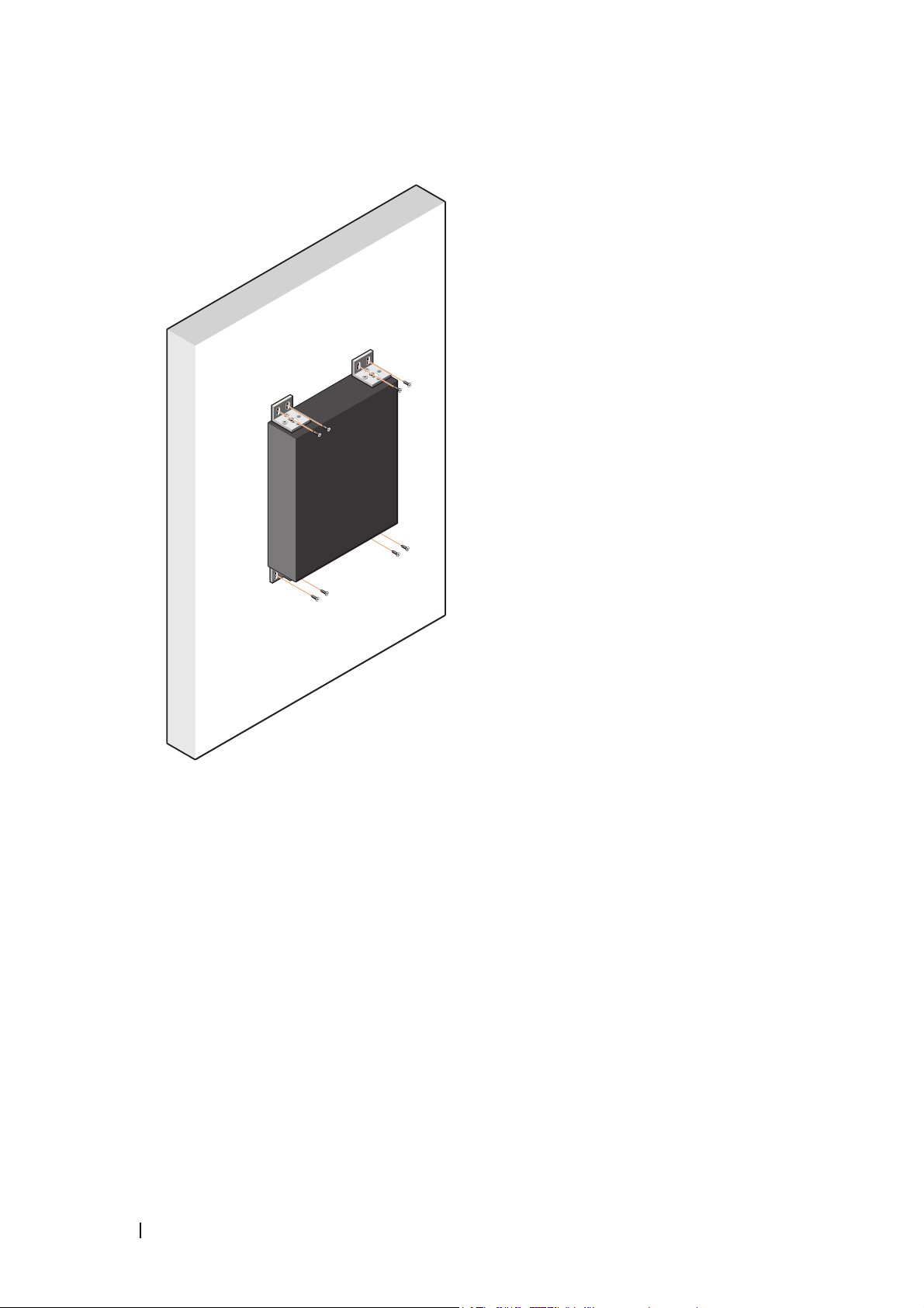
Figure 1-5. Mounting on a Wall
12 Getting Started Guide
Page 14
N1124T-ON/N1124P-ON/N1148T-ON/
N1148P-ON Installation
Rack Mounting an N1124T-ON/N1124P-ON/
N1148T-ON/ N1148P-ON Switch
WARNING: Read the safety information in the
as well as the safety information for other switches that connect to or support the
switch.
The AC power connector is on the rear panel of the switch.
Safety and Regulatory Information
Installing in a Rack
WARNING: Do not use rack mounting kits to suspend the switch from under a
table or desk, or attach it to a wall.
CAUTION: Disconnect all cables from the switch before continuing. Remove all
self-adhesive pads from the underside of the switch, if they have been attached.
CAUTION: When mounting multiple switches into a rack, mount the switches
from the bottom up.
1
Place the supplied rack-mounting bracket on one side of the switch,
ensuring that the mounting holes on the switch line up to the mounting
holes in the rack-mounting bracket. Figure 1-6 illustrates where to mount
the brackets.
Figure 1-6. Attaching the Brackets
Getting Started Guide 13
Page 15

2
Insert the supplied bolts into the rack-mounting holes and tighten with a
screwdriver.
3
Repeat the process for the rack-mounting bracket on the other side of the
switch.
4
Insert the switch into the 48.26 cm (19 inch) rack, ensuring that the rackmounting holes on the bracket line up with the mounting holes in the rack.
5
Secure the bracket to the rack with either the rack bolts or cage nuts and
cage-nut bolts with washers (depending on the kind of rack you have).
Fasten the bolts on the bottom before fastening the bolts on the top.
CAUTION: Make sure that the supplied rack bolts fit the pre-threaded holes in the
rack.
NOTE: Make sure that the ventilation holes are not obstructed.
Installing as a Free-standing Switch
NOTE: Dell strongly recommends mounting the switch in a rack.
Install the switch on a flat surface if you are not installing it in a rack. The
surface must be able to support the weight of the switch and the switch
cables. The switch is supplied with four self-adhesive rubber pads.
1
Attach the self-adhesive rubber pads on each location marked on the
bottom of the switch.
2
Set the switch on a flat surface, and make sure that it has proper ventilation
by leaving 5 cm (2 inches) on each side and 13 cm (5 inches) at the back.
Stacking Multiple N1124T-ON/N1124P-ON/
N1148T-ON/ N1148P-ON Switches
You can stack N1124T-ON/N1124P-ON/N1148T-ON/ N1148P-ON switches
up to four switches high using 10G SFP+ ports on the front of the switch.
The ports must be configured to support stacking. When multiple switches
are connected together through the stack ports, they operate as a single unit
with up to 208 front-panel ports. The stack operates and is managed as a
single entity. Refer to the User Configuration Guide and the CLI Reference
Guide for more information.
14 Getting Started Guide
Page 16
Starting and Configuring the
N1100-ON Series Switch
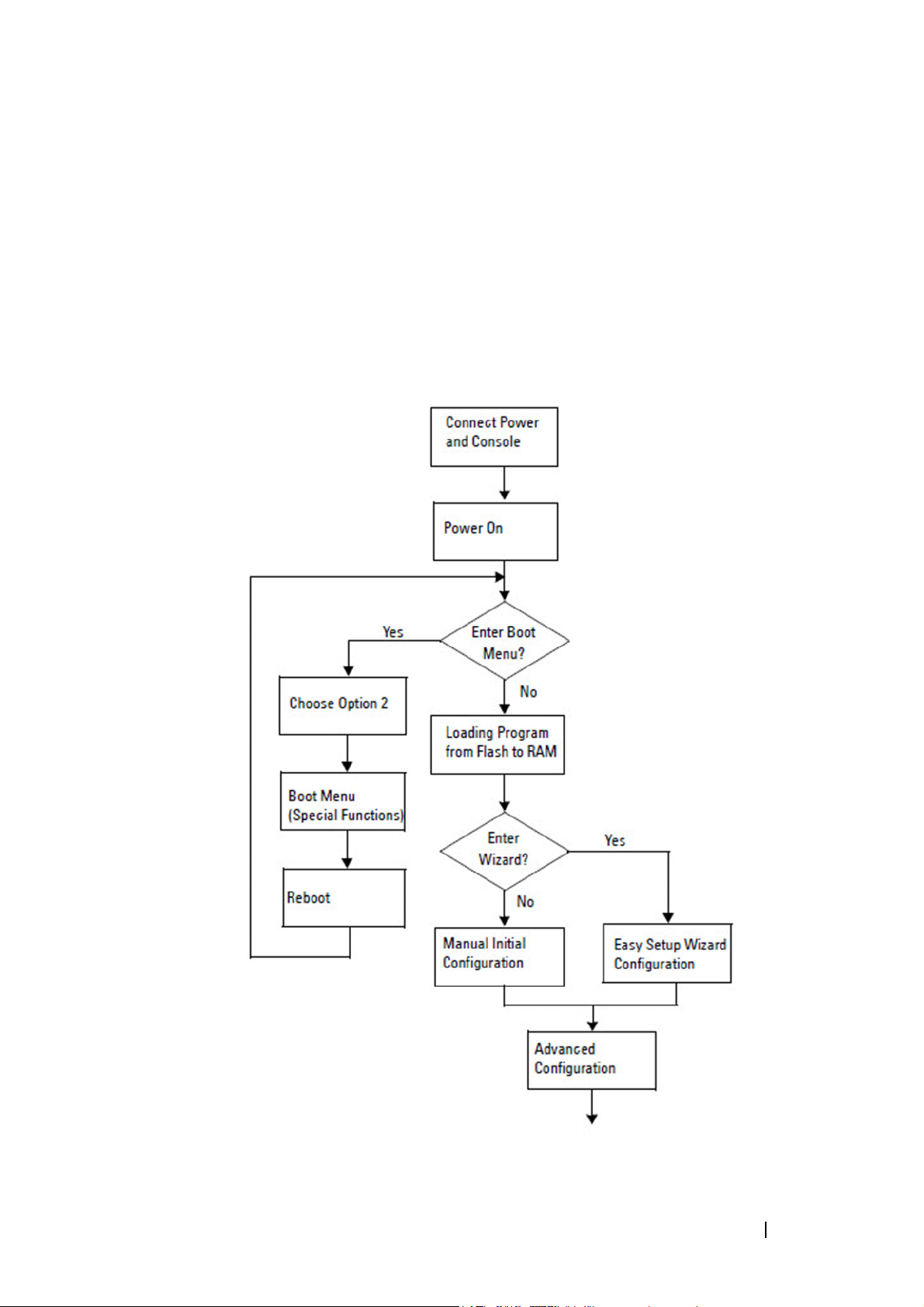
The following flow chart provides an overview of the steps you use to perform
the initial configuration after the switch is unpacked and mounted.
Figure 1-7. Installation and Configuration Flow Chart
Getting Started Guide 15
Page 17

Connecting an N1100-ON Series Switch to a
Terminal
After completing all external connections, configure the switch by connecting
it to a terminal.
NOTE: Read the Release Notes for this product before proceeding. You can
download the Release Notes from the Dell Support website at dell.com/support.
NOTE: Dell recommends that you obtain the most recent version of the user
documentation from the Dell Support website at dell.com/support.
To monitor and configure the switch via the USB console, use the console
port on the front panel of the switch to connect it to a computer running
VT100 terminal emulation software using the supplied USB cable. It may be
necessary to download and install a driver on first use of the USB cable.
The following equipment is required to use the console port:
• VT100-compatible computer with a USB port running VT100 terminal
emulation software,
• The supplied USB cable with a type B USB connector for the console port
and USB connector for the host PC.
Perform the following tasks to connect a terminal to the switch console port:
Connect the USB type B connector on the supplied switch and connect
1
the other end to a computer running VT100 terminal emulation software.
2
Configure the terminal emulation software as follows:
a
Select the appropriate serial port (for example, COM 1) to connect to
the console.
b
Set the data rate to 115,200 baud.
c
Set the data format to 8 data bits, 1 stop bit, and no parity.
d
Set the flow control to none.
e
Set the terminal emulation mode to
f
Select Terminal keys for Function, Arrow, and Ctrl keys. Make sure
such as HyperTerminal® and a USB driver.
VT100
.
that the setting is for Terminal keys (not Microsoft Windows keys).
3
Connect the USB type B connector on the cable directly to the switch
console port. The Dell Networking console port is located on the right side
of the front panel and is labeled with a
16 Getting Started Guide
|O|O|
symbol.
Page 18

NOTE: Console access to the stack manager is available from any console
port via the local CLI. Only one USB console session at a time is supported.
Connecting an N1100-ON Series Switch to a
Power Source
CAUTION: Read the safety information in the
manual as well as the safety information for other switches that connect to or
support the switch.
The N1108T-ON and N1108P-ON models have one internal power supply.
power receptacle is on the rear panel. N1108EP-ON uses an external DC
The
power adaptor. The external DC power adaptor
Safety and Regulatory Information
AC and DC Power Connection
1
Make sure that the switch console port is connected to a PC running a
VT100 terminal emulator via the USB to USB Type B cable.
2
Using a 5-foot (1.5 m) standard power cable with safety ground connected,
connect the power cable to the AC main receptacle located on the rear
panel.
The PoE model switches have a heavy-duty power cable with a notched
connector for the switch power receptacle. Use of this type of cable is
mandatory for PoE-capable switches.
3
Connect the power cable to a grounded AC outlet.
Getting Started Guide 17
Page 19

Booting the N1100-ON Series Switch
When the power is turned on with the local terminal already connected, the
switch goes through a power-on self-test (POST). POST runs every time the
switch is initialized and checks hardware components to determine if the
switch is fully operational before completely booting. If POST detects a
critical problem, the program flow stops. If POST passes successfully, valid
firmware is loaded into RAM. POST messages are displayed on the terminal
and indicate test success or failure. The boot process runs for approximately
60 seconds.
You can invoke the Boot menu after the first part of the POST is completed.
From the Boot menu, you can perform configuration tasks such as resetting
the system to factory defaults, activating the backup image, or recovering a
password. For more information about the Boot menu functions, refer to the
CLI Reference Guide.
18 Getting Started Guide
Page 20

Performing the N1100-ON Series Initial
Configuration
The initial configuration procedure is based on the following assumptions:
• The Dell Networking switch was never configured before.
• The Dell Networking switch booted successfully.
• The console connection was established, and the
prompt appears on the screen of a PC running terminal emulation
software.
The initial switch configuration is performed through the console port. After
the initial configuration, you can manage the switch from the alreadyconnected console port or remotely through an interface defined during the
initial configuration.
NOTE: The switch is not configured with a default user name, password, or IP
address.
Before setting up the initial configuration of the switch, obtain the following
information from your network administrator:
• The IP address to be assigned to the management interface.
• The IP subnet mask for the network.
• The IP address of the management interface default gateway.
These settings are necessary to allow the remote management of the switch
Dell Easy Setup Wizard
through Telnet (Telnet client) or HTTP (Web browser).
Enabling Remote Management
On the N1100-ON Series switches, you can use any of the switch ports on the
front panel for in-band management. By default, all in-band ports are
members of VLAN 1.
The Dell Easy Setup Wizard includes prompts to configure network
information for the VLAN 1 interface on the N1100-ON Series switches. You
can assign a static IP address and subnet mask or enable DHCP and allow a
network DHCP server to assign the information.
Refer to the CLI Reference Guide for commands to configure network
information.
Getting Started Guide 19
Page 21

Initial Configuration Procedure
Perform the initial configuration by using the Dell Easy Setup Wizard or by
using the CLI. The wizard automatically starts when the switch configuration
file is empty. Exit the wizard at any point by entering [ctrl+z], but all
configuration settings specified will be discarded, and the switch will use the
default values.
NOTE: If you do not run the Dell Easy Setup Wizard or do not respond to the initial
Easy Setup Wizard prompt within 60 seconds, the switch enters CLI mode. You must
reset the switch with an empty startup configuration in order to rerun the Dell Easy
Setup Wizard.
For more information about performing the initial configuration by using the
CLI, refer to the CLI Reference Guide. This Getting Started Guide shows how
to use the Dell Easy Setup Wizard for initial switch configuration. The wizard
sets up the following configuration on the switch:
• Establishes the initial privileged user account with a valid password. The
wizard configures one privileged user account during the setup.
• Enables CLI login and HTTP access to use the local authentication setting
only.
• Sets up the IP address for the VLAN 1 routing interface, of which all
in-band ports are members.
• Sets up the SNMP community string to be used by the SNMP manager at
a given IP address. Skip this step if SNMP management is not used for this
switch.
• Allows you to specify the network management system IP address or
permit management access from all IP addresses.
• Configures the default gateway IP address for the VLAN 1 interface.
20 Getting Started Guide
Page 22

Example Session
This section describes a Dell Easy Setup Wizard session. The following
values are used by the example session:
• The SNMP community string to be used is
• The network management system (NMS) IP address is
• The user name is
admin
, and the password is
• The IP address for the VLAN 1 routing interface is
subnet mask of
255.255.255.0
• The default gateway is
10.1.1.1.
.
public
.
admin123
10.1.2.100
.
10.1.1.200
.
with a
The setup wizard configures the initial values as defined above. After
completing the wizard, the switch is configured as follows:
• SNMPv2 is enabled and the community string is set up as defined above.
SNMPv3 is disabled by default.
• The admin user account is set up as defined.
• A network management system is configured. From the management
station, you can access the SNMP, HTTP, and CLI interfaces. You may also
choose to allow all IP addresses to access these management interfaces by
choosing the (0.0.0.0) IP address.
• An IP address is configured for the VLAN 1 routing interface.
• A default gateway address is configured.
NOTE: In the following example, the possible user options or default values are
enclosed in [ ]. If you press <Enter> with no options defined, the default value is
accepted. Help text is in parentheses.
Getting Started Guide 21
Page 23

Dell Easy Setup Wizard Console Example
The following example contains the sequence of prompts and responses
associated with running an example Dell Easy Setup Wizard session, using
the input values listed earlier.
After the switch completes the POST and is booted, the following dialog
appears:
Unit 1 - Waiting to select management unit)>
___________Dell SupportAssist EULA__________________
I accept the terms of the license agreement. You can
reject the license agreement by configuring this
command 'eula-consent support-assist reject'.
By installing SupportAssist, you allow Dell to save
your contact information (e.g. name, phone number
and/or email address) which would be used to provide
technical support for your Dell products and services
Dell may use the information for providing
recommendations to improve your IT infrastructure.
Dell SupportAssist also collects and stores machine
diagnostic information, which may include but is not
limited to configuration information, user supplied
contact information, names of data volumes, IP
addresses, access control lists, diagnostics &
performance information, network configuration
information, host/server configuration & performance
information and related data (Collected Data) and
transmits this information to Dell. By downloading
SupportAssist and agreeing to be bound by these terms
and the Dell end user license agreement, available at:
http://www.dell.com/aeula, you agree to allow Dell to
provide remote monitoring services of your IT
environment and you give Dell the right to collect the
Collected Data in accordance with Dell's Privacy
Policy, available at:
http://www.dell.com/privacypolicycountryspecific, in
order to enable the performance of all of the various
functions of SupportAssist during your entitlement to
22 Getting Started Guide
Page 24

receive related repair services from Dell. You further
agree to allow Dell to transmit and store the
Collected Data from SupportAssist in accordance with
these terms. You agree that the provision of
SupportAssist may involve international transfers of
data from you to Dell and/or to Dell's affiliates,
subcontractors or business partners. When making such
transfers, Dell shall ensure appropriate protection is
in place to safeguard the Collected Data being
transferred in connection with SupportAssist. If you
are downloading SupportAssist on behalf of a company
or other legal entity, you are further certifying to
Dell that you have appropriate authority to provide
this consent on behalf of that entity. If you do not
consent to the collection, transmission and/or use of
the Collected Data, you may not download, install or
otherwise use SupportAssist.
________AeroHive HiveManager NG EULA________________
This switch includes a feature that enables it to work
with HiveManager (an optional management suite), by
sending the switch's service tag number and IP Address
to HiveManager to authenticate your entitlement to use
HiveManager. If you wish to disable this feature, you
should run command 'eula-consent hiveagent reject'
immediately upon powering up the switch for the first
time, or at any time thereafter.
Applying Global configuration, please wait...
Welcome to Dell Easy Setup Wizard
The setup wizard guides you through the initial switch
configuration, and gets you up and running as quickly
as possible. You can skip the setup wizard, and enter
CLI mode to manually configure the switch. You must
respond to the next question to run the setup wizard
within 60 seconds, otherwise the system will continue
Getting Started Guide 23
Page 25

with normal operation using the default system
configuration. Note: You can exit the setup wizard at
any point by entering [ctrl+z].
Would you like to run the setup wizard (you must
answer this question within 60 seconds)? [Y/N] y
Step 1:
The system is not set up for SNMP management by
default. To manage the switch using SNMP (required for
Dell Network Manager) you can
. Set up the initial SNMP version 2 account now.
. Return later and set up other SNMP accounts. (For
more information on setting up an SNMP version 1 or
3 account, see the user documentation).
Would you like to set up the SNMP management interface
now? [Y/N] y
To set up the SNMP management account you must specify
the management system IP address and the “community
string” or password that the particular management
system uses to access the switch. The wizard
automatically assigns the highest access level
[Privilege Level 15] to this account. You can use Dell
Network Manager or other management interfaces to
change this setting, and to add additional management
system information later. For more information on
adding management systems, see the user documentation.
To add a management station:
Please enter the SNMP community string to be used.
[public]: public
NOTE: If it is configured, the default access level is set to the highest available
access for the SNMP management interface. Initially only SNMPv2 will be
activated. SNMPv3 is disabled until you return to configure security access for
SNMPv3 (e.g. engine ID, view, etc.).
Please enter the IP address of the Management System
(A.B.C.D) or wildcard (0.0.0.0) to manage from any
Management Station. [0.0.0.0]: 10.1.2.100
24 Getting Started Guide
Page 26

Step 2:
Now we need to set up your initial privilege (Level
15) user account. This account is used to login to the
CLI and Web interface. You may set up other accounts
and change privilege levels later. For more
information on setting up user accounts and changing
privilege levels, see the user documentation.
To set up a user account:
Please enter the user name. [root]:admin
Please enter the user password: ********
Please reenter the user password: ********
Step 3:
Next, an IP address is set up on the VLAN 1 routing
interface.
You can use the IP address to access the CLI, Web
interface, or SNMP interface of the switch.
To access the switch through any Management Interface
you can
. Set up the IP address for the Management Interface.
. Set up the default gateway if IP address is
manually configured on the routing interface.
Step 4:
Would you like to set up the VLAN1 routing interface
now? [Y/N] y
Please enter the IP address of the device (A.B.C.D) or
enter “DHCP” (without the quotes) to automatically
request an IP address from the network DHCP server:
10.1.1.200
Please enter the IP subnet mask (A.B.C.D or /nn):
255.255.255.0
Step 5:
Getting Started Guide 25
Page 27

Finally, set up the default gateway. Please enter the
IP address of the gateway from which this network is
reachable. [0.0.0.0]: 10.1.1.1
This is the configuration information that has been
collected:
SNMP Interface = “public”@10.1.2.100
User Account setup = admin
Password = ********
VLAN1 Router Interface IP = 10.1.1.200 255.255.255.0
Default Gateway = 10.1.1.1
Step 6:
If the information is correct, please enter (Y) to
save the configuration and copy the settings to the
start-up configuration file. If the information is
incorrect, enter (N) to discard the configuration and
restart the wizard: [Y/N] y
Thank you for using the Dell Easy Setup Wizard. You
will now enter CLI mode.
Applying Interface configuration, please wait...
Next Steps
After completing the initial configuration described in this section, connect
any of the front-panel switch ports to a production network for in-band
remote management.
If you specified DHCP for the VLAN 1 management interface IP address, the
interface will acquire its IP address from a DHCP server on the network. To
discover the dynamically assigned IP address, use the console port connection
to issue the following command:
• For the VLAN 1 routing interface, enter
To access the Dell OpenManage Switch Administrator interface, enter the
VLAN 1 management interface IP address into the address field of a Web
browser. For remote management access to the CLI, enter the VLAN 1
show ip interface
.
management interface IP address into a Telnet or SSH client. Alternatively,
continue to use the console port for local CLI access to the switch.
26 Getting Started Guide
Page 28

The N1100-ON Series switches support basic switching features such as
VLANs and spanning tree protocol. Use the Web-based management
interface or the CLI to configure the features your network requires. For
information about how to configure the switch features, refer to the User
Configuration Guide or CLI Reference Guide available on the support site:
dell.com/support.
Getting Started Guide 27
Page 29

Agency compliance
The N1108T-ON, N1108P-ON, N1108EP-ON, N1124T-ON, N1124P-ON,
N1148T-ON, and N1148P-ON switches comply with the following safety and
agency requirements:
European Union EMC directive conformance
statement
This product is in conformity with the protection requirements of EU
Council Directive 2004/30/EC on the approximation of the laws of the
Member States relating to electromagnetic compatibility. Dell EMC cannot
accept responsibility for any failure to satisfy the protection requirements
resulting from a non-recommended modification of this product, including
the fitting of non-Dell EMC option cards.
This product has been tested and found to comply with the limits for Class A
Information Technology Equipment according to CISPR 32/CISPR34 and
EN55032 / EN55034. The limits for Class A equipment were derived for
commercial and industrial environments to provide reasonable protection
against interference with licensed communication equipment.
WARNING:
radio interference, in which case, you may be required to take adequate
measures.
European Community Contact:
Dell EMC, EMEA - Central
Dahlienweg 19
66265 Heusweiler
Germany
Tel: +49 172 6802630
Email: EMEA Central Sales
This is a Class A product. In a domestic environment, this device may cause
India certification of compliance
The product conforms to the relevant Essential Requirements of
Telecommunication Engineering Centre (TEC) regulations.
28 Getting Started Guide
Page 30

Safety standards and compliance agency
certifications
• IEC 62368-1, 2nd Edition
• CUS UL 60950-1, 2nd Edition
• Meets or exceeds Hi Pot and Ground Continuity testing per UL
60950-1.
• AS/NZS 60950
• CSA 60950-1-03, 2nd Edition
• EN 60950-1, 2nd Edition
• EN 60825-1, 1st Edition
• EN 60825-1 Safety of Laser Products—Part 1: Equipment Classification
Requirements and User’s Guide
• EN 60825-2 Safety of Laser Products—Part 2: Safety of Optical Fibre
Communication Systems
• FDA Regulation 21CFR 1040.10 and 1040.11
• IEC 60950-1, 2nd Ed, including all National Deviations and Group
Differences
Electromagnetic compatibility
Emissions
• International: CISPR 32: Class A
• Australia/New Zealand: AS/NZS CISPR 32, Class A
• Canada: ICES-003, Issue-4, Class A
• Europe: EN55032:2015 (CISPR 32), Class A
• EN55032
• Japan: VCCI Class A
•Korea: KN32, Class A
• Taiwan: CNS13438, Class A
• USA: FCC CFR47 Part 15, Subpart B, Class A
Getting Started Guide 29
Page 31

Immunity
• EN 300 386 EMC for Network Equipment
• EN 55024
• EN 61000-3-2 Harmonic Current Emissions
• EN 61000-3-3 Voltage Fluctuations and Flicker
• EN 61000-4-2 ESD
• EN 61000-4-3 Radiated Immunity
• EN 61000-4-4 EFT
• EN 61000-4-5 Surge
• EN 61000-4-6 Low Frequency Conducted Immunity
Product recycling and disposal
You must recycle or discard this system according to applicable local and
national regulations. Dell EMC encourages owners of information technology
(IT) equipment to responsibly recycle their equipment when it is no longer
needed. Dell EMC offers a variety of product return programs and services in
several countries to assist equipment owners in recycling their IT products.
Waste Electrical and Electronic Equipment
(WEEE) directive for recovery, recycle, and reuse
of IT and telecommunications products
Dell EMC switches are labeled in accordance with European Directive
2002/96/EC concerning waste electrical and electronic equipment (WEEE).
The Directive determines the framework for the return and recycling of used
appliances as applicable throughout the European Union. This label is
applied to various products to indicate that the product is not to be thrown
away, but rather reclaimed upon end of life per this Directive.
30 Getting Started Guide
Page 32

Figure 1-8. The European WEEE symbol
In accordance with the European WEEE Directive, electrical and electronic
equipment (EEE) is to be collected separately and to be reused, recycled, or
recovered at end of life. Users of EEE with the WEEE marking per Annex IV
of the WEEE Directive, as shown above, must not dispose of end of life EEE
as unsorted municipal waste, but use the collection framework available to
customers for the return, recycling and recovery of WEEE. Customer
participation is important to minimize any potential effects of EEE on the
environment and human health due to the potential presence of hazardous
substances in EEE.
Dell EMC products, which fall within the scope of the WEEE, are labeled
with the crossed-out wheelie-bin symbol, as shown above, as required by
WEEE.
For information on Dell EMC product recycling offerings, see the WEEE
Recycling instructions on the Support page. For more information, contact
the Dell EMC Technical Assistance Center.
.
Getting Started Guide 31
Page 33

32 Getting Started Guide
Page 34

Dell Networking
N1108T-ON/N1108P-ON/
N1108EP-ON/N1124T-ON/
N1124P-ON/N1148T-ON/
N1148P-ON
Guide de mise en route
Modèles réglementaires : E17W et E18W
Page 35

Remarques, précautions et avertissements
REMARQUE: REMARQUE signale des informations importantes qui vous aident à
mieux utiliser votre commutateur.
PRÉCAUTION: Une PRÉCAUTION indique un risque d’endommagement du
matériel ou de perte de données et vous indique comment éviter le problème.
AVERTISSEMENT: Un AVERTISSEMENT indique un risque d’endommagement du
matériel, de blessures corporelles ou même de mort.
Précaution au sujet des batteries au lithium :
• Il existe un danger d’explosion dans le cas où une batterie ne serait pas
remplacée correctement. Remplacez la batterie uniquement par une
batterie identique ou de type équivalent. Mettez les batteries usagées
au rebut selon les instructions du fabricant.
• Jeter une batterie dans un feu, un four haute température, l’écraser
mécaniquement ou la couper peut entraîner son explosion.
• Laisser la batterie dans un milieu extrêmement chaud peut entraîner des
fuites de liquide ou de gaz inflammable ou entraîner une explosion.
• Soumettre la batterie à une faible pression atmosphérique peut entraîner
une fuite de liquide ou de gaz inflammable ou une explosion.
• L’appareil doit uniquement être utilisé dans un emplacement fixe, tel
qu’un laboratoire ou une salle des machines. Lors de l’installation de
l’appareil, assurez-vous de faire vérifier le branchement de mise à la terre
de la prise par une personne compétente.
___________________
© 2019 Dell Inc. ou ses filiales. Tous droits réservés. Le présent produit est protégé par les législations
américaine et internationale sur le droit d’auteur et la propriété intellectuelle. Dell et le logo Dell sont
des marques de Dell Inc. aux États-Unis et/ou dans d’autres pays. Toutes les autres marques et tous
les noms de produits mentionnés dans ce document peuvent être des marques de leurs sociétés
respectives.
Modèles réglementaires : E17W et E18W
Mai 2019 N/P Y7208 Rév. A01
Page 36

Table des matières
1 Introduction . . . . . . . . . . . . . . . . . . . . . . . 37
Présentation du matériel Série N1100-ON . . . . . . . 37
Consommation électrique des commutateurs
PoE Série N1100-ON
. . . . . . . . . . . . . . . . 37
Système de ventilation
Résumé du modèle Série N1100-ON
. . . . . . . . . . . . . . . 39
. . . . . . . . . . . 39
2 Installation des commutateurs
N1108T-ON/N1108P-ON/N1108EP-ON
Montage d’un commutateur N1108T-ON/N1108P-ON
à l’aide d’un plateau tandem Dell
Montage d’un commutateur N1108T-ON/N1108P-ON/
N1108EP-ON sur un rack à deux montants à l’aide
de grands supports en L
Montage mural pour tous les commutateurs
N11xx-ON
. . . . . . . . . . . . . . . . . . . . . . . . 42
. . . . . . . . . . . . . . . . . 41
. . . . . . . . . . . . 40
. . . 40
3 Installation des N1124T-ON/
N1124P-ON/N1148T-ON/ N1148P-ON
Montage en rack d’un commutateur N1124T-ON/
N1124P-ON/ N1148T-ON/ N1148P-ON
Installation dans un rack
Installation en tant que commutateur autonome
Empilage de plusieurs commutateurs N1124T-ON/
N1124P-ON/ N1148T-ON/ N1148P-ON
. . . . . . . . . . . . . . 45
. . . 45
. . . . . . . . . . 45
. 46
. . . . . . . . . . 46
Table des matières 35
Page 37

4 Démarrage et configuration des
commutateurs Série N1100-ON
Connexion d’un commutateur Série N1100-ON
à un terminal
Série N1100-ONConnexion d’un commutateur
à une source d’alimentation
Connexion du câble d’alimentation
secteur et CC
Démarrage du commutateur Série N1100-ON
Réalisation de la configuration initiale du
Série N1100-ON
Activation de la gestion à distance
Procédure de configuration initiale
Exemple de session
. . . . . . . . . . . . . . . . . . . . . . . 48
. . . . . . . . . . . . . . . 49
. . . . . . . . . . . . . . . . . . . . 49
. . . . . . . . . . . . . . . . . . . . . 51
. . . . . . . . . . . . . . . . . 53
. . . . . . . . 47
. . . . . . 50
. . . . . . . . . 51
. . . . . . . . . 52
Exemple de la console Assistant Dell
d’installation facile
Étapes suivantes
. . . . . . . . . . . . . . . . . 54
. . . . . . . . . . . . . . . . . . 58
5 Conformité avec les organismes . . . . . . 60
36 Table des matières
Page 38

Introduction
Ce document fournit des informations de base concernant les commutateurs
Dell Networking Série N1100-ON, y compris leur installation et leur
configuration initiale. Pour en savoir plus sur la façon de configurer et surveiller
les fonctions du commutateur, reportez-vous au User Configuration Guide
(Guide de configuration utilisateur), qui est disponible sur le site Web du
support de Dell dell.com/support. Consultez le site web du support pour
obtenir les dernières mises à jour de la documentation et du micrologiciel.
REMARQUE: Il est fortement recommandé aux administrateurs des commutateurs
de veiller à ce que les commutateurs Dell Networking soient toujours équipés de
la version la plus récente de DNOS Dell Networking, le système d’exploitation Dell
Networking. Dell Networking améliore en permanence les caractéristiques et les
fonctions de DNOS à partir des commentaires de nos clients. Pour les infrastructures
critiques, il est recommandé de pré-activer la nouvelle version dans une partie non
critique du réseau afin de vérifier la configuration réseau et le bon fonctionnement
avec la nouvelle version DNOS.
Présentation du matériel Série N1100-ON
Cette section contient des informations relatives aux caractéristiques de
l’appareil et aux configurations matérielles modulaires du commutateur
Dell Networking Série N1100-ON.
REMARQUE:
kit de montage n’est disponible pour l’adaptateur secteur externe du commutateur
N1108EP-ON. Lors de l’installation du commutateur N1108EP-ON, placez l’adaptateur
secteur externe à l’écart du commutateur.
Consommation électrique des commutateurs PoE Série N1100-ON
Le Tableau 1-1 décrit la consommation d’énergie des commutateurs PoE Série
N1100-ON. Le bilan de puissance des commutateurs PoE est de 60 W pour les
modèles N1108P-ON, de 123 W pour les modèles N1108EP-ON, de 185 W
pour les modèles N1124P-ON et de 370 W pour les modèles N1148P-ON.
Le commutateur N1108EP-ON utilise un adaptateur secteur externe. Aucun
Guide de mise en route 37
Page 39

Tableau 1-1. Consommation électrique des commutateurs PoE Série N1100-ON
Modèle Tension
d’entrée
N1108P-ON 100 V/60 Hz PSU principal 0,95 A 88,64 W
110 V/60 Hz PSU principal 0,87 A 88,43 W
120 V/60 Hz PSU principal 0,80 A 88,22 W
220 V/50 Hz PSU principal 0,49 A 89,28 W
240 V/50 Hz PSU principal 0,45 A 89,70 W
N1108EP-ON 100 V/60 Hz Adaptateur secteur
110 V/60 Hz Adaptateur secteur
120 V/60 Hz Adaptateur secteur
Configuration du bloc
d’alimentation
externe 54 VCC
externe 54 VCC
externe 54 VCC
Consommation
maximale de
courant
constant (A)
1,62 A 157 W
1,47 A 157 W
1,35 A 157 W
Puissance
constante
maximale
(en W)
220 V/50 Hz Adaptateur secteur
externe 54 VCC
240 V/50 Hz Adaptateur secteur
externe 54 VCC
N1124P-ON 100 V/60 Hz PSU principal 2,66 A 260,66 W
110 V/60 Hz PSU principal 2,38 A 257,95 W
120 V/60 Hz PSU principal 2,16 A 256,27 W
220 V/50 Hz PSU principal 1,18 A 250,52 W
240 V/50 Hz PSU principal 1,10 A 251,25 W
N1148P-ON 100 V/60 Hz PSU principal 4,78 A 476,03 W
110 V/60 Hz PSU principal 4,32 A 472,64 W
120 V/60 Hz PSU principal 3,95 A 470,58 W
220 V/50 Hz PSU principal 2,14 A 459,37 W
240 V/50 Hz PSU principal 1,97 A 459,06 W
0,74 A 157 W
0,67 A 157 W
38 Guide de mise en route
Page 40

Système de ventilation
Un seul ventilateur refroidit les commutateurs N1108T-ON/N1108P-ON et
deux ventilateurs refroidissent les commutateurs N1024T-ON/N1024P-ON/
N1048T-ON/N1048P-ON. Les ventilateurs ne sont pas remplaçables sur le
terrain. Le commutateur N1108EP-ON n’est pas équipé d’un ventilateur.
Résumé du modèle Série N1100-ON
Tableau 1-2. Numéros réglementaires du commutateur Série N1100-ON
Nom de
commercialisation
du modèle (MMN)
N1108T-ON Ports SFP 10X1G/2x1G DPS-24GP E17W E17W001
N1108P-ON Ports 10 x 1G/2 x 1G
N1108EP-ON Ports 8 x 1 G PoE+/2 x 1 G PD/
N1124T-ON Ports 24 x 1 G/4 x 10 G SFP+ DPS-40AP E18W E18W001
N1124P-ON Ports 24 x 1 G/4 x 10 G SFP+/
N1148T-ON Ports 48 x 1 G/4 x 10 G SFP+ DPS-60AP E18W E18W002
N1148P-ON Port 48 x 1 G/4 x 10 G SFP+/
Description Bloc
d’alimentation
(PSU)
DPS-80AP/
SFP/2 x PoE+
2x1G SFP
6 x PoE+
12 x PoE+
DPS-24GP
ADP-280BR E48W E48W001
EDPS-250BF E18W E18W001
YM-2501D E18W E18W002
Numéro
de modèle
règlementaire
(RMN)
E17W E17W001
Numéro
de type
règlementaire
(RTN)
Guide de mise en route 39
Page 41

Installation des commutateurs
N1108T-ON/N1108P-ON/N1108EP-ON
Montage d’un commutateur N1108T-ON/N1108P-ON
à l’aide d’un plateau tandem Dell
Le connecteur d’alimentation CA se trouve sur le panneau arrière.
AVERTISSEMENT: Prenez connaissance des consignes de sécurité exposées
dans le manuel
réglementation et la sécurité)
des autres commutateurs qui se connectent au commutateur ou qui le prennent
en charge.
AVERTISSEMENT: N’utilisez pas les kits de montage en rack pour fixer le
commutateur sous une table ou un bureau, ni pour une installation murale.
Safety and Regulatory Information (Informations relatives à la
ainsi que des informations relatives à la sécurité
PRÉCAUTION: Déconnectez tous les câbles du commutateur avant de continuer.
Retirez tous les patins adhésifs qui ont pu être fixés sous le commutateur.
PRÉCAUTION: Si vous installez plusieurs commutateurs dans un rack, montez-les
de bas en haut.
1
Fixez le commutateur N1108T-ON/N1108P-ON dans le kit de plateau
tandem Dell (Dell Tandem Tray Kit), comme illustré dans la Figure 1-1.
Figure 1-1. Dell Tandem Tray Kit
40 Guide de mise en route
Page 42

2
Insérez le commutateur dans le rack de 48,26 cm (19 pouces) en veillant à
ce que les orifices de montage en rack situés sur le kit s’alignent bien sur
ceux du rack.
3
Fixez le kit sur le rack en utilisant les boulons de rack ou les écrous à cage
et les écrous à cage avec rondelles (selon le type du rack). Fixez d’abord les
boulons sur le bas avant de fixer ceux du haut.
Montage d’un commutateur N1108T-ON/N1108P-ON/
N1108EP-ON sur un rack à deux montants à l’aide
de grands supports en L
REMARQUE: Le connecteur d’alimentation CA se trouve sur le panneau arrière des
commutateurs N1108T-ON/N1108P-ON. Le connecteur d’alimentation CC du
commutateur N1108EP-ON se trouve au centre du panneau arrière.
REMARQUE: Le commutateur N1108EP-ON utilise un adaptateur secteur externe. Aucun
kit de montage n’est disponible pour l’adaptateur secteur externe du
commutateur N1108EP-ON. Lors de l’installation du commutateur N1108EP-ON,
placez l’adaptateur secteur externe à l’écart du commutateur.
PRÉCAUTION: Comme le commutateur N1108EP-ON n’est pas équipé d’un ventilateur,
ne placez pas l’adaptateur secteur externe sur la partie supérieure du
commutateur afin d’éviter toute surchauffe.
1
Placez le support de montage en rack fourni sur un côté du commutateur,
en alignant bien les orifices de montage du commutateur avec ceux situés
sur le support de montage en rack. Voir l’élément 1 dans la Figure 1-2.
Figure 1-2. Installation à l’aide d’un kit de grands supports en L
Guide de mise en route 41
Page 43

2
Insérez les vis fournies dans les orifices de montage en rack et serrez-les à
l’aide d’un tournevis.
3
Répétez l’opération de l’autre côté du commutateur.
4
Insérez l’assemblage du commutateur et du rail dans le rack depuis l’avant
du rack. Assurez-vous de bien aligner les orifices de montage en rack du
commutateur avec ceux du rack.
5
Fixez le commutateur au rack à l’aide des vis du rack. Fixez les vis du bas
avant les vis du haut. Voir la Figure 1-3.
Figure 1-3. Installation sur un rack à deux montants avec des supports en L
Montage mural pour tous les commutateurs
N11xx-ON
1
Assurez-vous que l’emplacement de l’installation répond bien aux
conditions suivantes :
• La surface du mur peut soutenir le commutateur.
• L’emplacement est ventilé afin d’éviter une augmentation de la
température.
42 Guide de mise en route
Page 44

2
Placez le support de montage mural fourni sur un côté du commutateur,
en alignant bien les orifices de montage du commutateur avec ceux situés
sur le support de montage mural.
3
Insérez les vis fournies dans les orifices du support de montage mural et
serrez-les avec un tournevis. Voir la Figure 1-4.
Figure 1-4. Insertion des supports de montage
4
Répétez le processus pour le support de montage mural situé de l’autre
côté du commutateur.
5
Placez le commutateur sur le mur à l’endroit où il va être installé.
6
Marquez sur le mur l’emplacement des vis des supports du commutateur.
Guide de mise en route 43
Page 45

7
Percez les trous sur les emplacements que vous avez marqués et insérez les
huit chevilles fournies dans les trous.
8
Insérez les vis fournies dans les orifices des supports de montage mural et
serrez-les avec un tournevis. Voir la Figure 1-5.
Figure 1-5. Montage mural
44 Guide de mise en route
Page 46

Installation des N1124T-ON/
N1124P-ON/N1148T-ON/ N1148P-ON
Montage en rack d’un commutateur N1124T-ON/
N1124P-ON/ N1148T-ON/ N1148P-ON
AVERTISSEMENT: Prenez connaissance des consignes de sécurité exposées
dans le manuel
réglementation et la sécurité)
des autres commutateurs qui se connectent au commutateur ou qui le prennent en
charge.
Le connecteur d’alimentation secteur est situé sur le panneau arrière du
commutateur.
Installation dans un rack
AVERTISSEMENT: N’utilisez pas les kits de montage en rack pour fixer le
commutateur sous une table ou un bureau, ni pour une installation murale.
Safety and Regulatory Information (Informations relatives à la
ainsi que des informations relatives à la sécurité
PRÉCAUTION: Déconnectez tous les câbles du commutateur avant de continuer.
Retirez tous les patins adhésifs qui ont pu être fixés sous le commutateur.
PRÉCAUTION: Si vous installez plusieurs commutateurs dans un rack, montez-
les de bas en haut.
1
Placez sur un côté du commutateur le support de fixation en rack qui est
fourni, en alignant bien les orifices de montage du commutateur avec ceux
situés sur le support de montage en rack. La Figure 1-6 montre où monter
les supports.
Figure 1-6. Fixation des supports
Guide de mise en route 45
Page 47

2
Insérez les boulons fournis dans les orifices de montage en rack et serrez-les
à l’aide d’un tournevis.
3
Répétez le processus pour le support de montage situé sur l’autre côté du
commutateur.
4
Insérez le commutateur dans le rack de 48,26 cm (19 pouces) en faisant en
sorte que les orifices de montage en rack situés sur le support s’alignent sur
ceux du rack.
5
Fixez le support sur le rack en utilisant les boulons de rack ou les écrous à
cage et les écrous à cage avec rondelles (selon le type du rack). Fixez
d’abord les boulons sur le bas avant de fixer ceux du haut.
PRÉCAUTION: Assurez-vous que les boulons de rack fournis sont bien adaptés
aux orifices préfiletés du rack.
REMARQUE: Assurez-vous que rien n’obstrue les orifices de ventilation.
Installation en tant que commutateur autonome
REMARQUE: Dell recommande vivement de monter le commutateur dans un rack.
Installez le commutateur sur une surface plane si vous ne l’installez pas dans
un rack. La surface doit être capable de supporter le poids du commutateur et
de ses câbles. Le commutateur est fourni avec quatre coussinets en
caoutchouc auto-adhésifs.
1
Fixez les coussinets adhésifs sur les emplacements marqués en bas du
commutateur.
2
Placez le commutateur sur une surface plane. Assurez-vous qu’il a une
ventilation adéquate en laissant un espace de 5 cm (2 pouces) de chaque
côté et de 13 cm (5 pouces) à l’arrière.
Empilage de plusieurs commutateurs N1124T-ON/
N1124P-ON/ N1148T-ON/ N1148P-ON
Vous pouvez empiler jusqu’à quatre commutateurs
N1124T-ON/N1124P-ON/N1148T-ON/ N1148P-ON en vous servant des
ports 10G SFP+ situés à l’avant des commutateurs. Les ports doivent être
configurés pour prendre en charge l’empilage. Lorsque plusieurs commutateurs
sont connectés l’un à l’autre via les ports d’empilage, ils fonctionnent comme
une seule et même unité avec jusqu’à 208 ports du panneau avant. La pile
fonctionne et est gérée en tant qu’une seule et même entité. Pour plus
d’informations, reportez-vous au User Configuration Guide (Guide de
configuration utilisateur) et au CLI Reference Guide (Guide de référence
de l’interface CLI).
46 Guide de mise en route
Page 48

Démarrage et configuration des
commutateurs Série N1100-ON
Le diagramme qui suit donne une vue générale de la procédure à suivre pour
effectuer la configuration initiale une fois que le commutateur a été déballé
et monté.
Figure 1-7. Diagramme du flux d’installation et de configuration
Guide de mise en route 47
Page 49

Connexion d’un commutateur Série N1100-ON
à un terminal
Après avoir effectué toutes les connexions externes, configurez le
commutateur en le connectant à un terminal.
REMARQUE: Avant de continuer, lisez les notes de mise à jour concernant ce
produit. Vous pouvez télécharger les notes de mise à jour à partir du site web du
support de Dell dell.com/ support.
REMARQUE: Dell vous recommande de vous procurer la version la plus récente
de la documentation utilisateur, disponible sur le site dell.com/support.
Pour surveiller et configurer le commutateur via la console USB, utilisez le
port de console sur le panneau avant du commutateur pour le connecter à un
ordinateur exécutant un logiciel d’émulation de terminal VT100 à l’aide du
câble USB fourni. Il sera peut-être nécessaire de télécharger et installer un
pilote lors de la première utilisation du câble USB.
Pour utiliser le port de console, vous devez disposer des éléments suivants :
• Ordinateur compatible VT100 avec port USB exécutant un logiciel
d’émulation de terminal VT100,
pilote USB.
• Le câble USB qui est fourni avec un connecteur USB type B pour le port
de console et le connecteur USB pour l’ordinateur hôte.
Pour connecter un terminal au port de console du commutateur, procédez
comme suit :
1
Branchez le connecteur USB de type B sur le commutateur fourni et
connectez l’autre extrémité à un ordinateur exécutant un logiciel
d’émulation de terminal VT100.
2
Configurez le logiciel d’émulation de terminal comme suit :
a
Sélectionnez le port série approprié (par exemple, COM 1) pour
établir une connexion à la console.
b
Réglez le débit de données sur 115 200 bauds.
c
Réglez le format de données sur 8 data bits, 1 stop bit et no parity.
tel que HyperTerminal®, et avec
d
Définissez le contrôle de flux sur aucun.
e
Définissez le mode d’émulation de terminal sur
48 Guide de mise en route
VT100
.
Page 50

f
Choisissez l’option Touches de terminal pour les touches de fonction,
de direction et Ctrl. Assurez-vous que le paramètre correspond bien
aux touches de terminal (et non aux touches Microsoft Windows).
3
Branchez le connecteur USB de type B du câble directement sur le port de
console du commutateur. Le port de console du Dell Networking est situé
sur le côté droit du panneau avant et est identifiable par le symbole
|O|O|
.
REMARQUE: L’accès de la console au gestionnaire de pile est disponible à
partir de n’importe quel port de console via la CLI locale. Une seule session
de console USB à la fois est possible.
Série N1100-ONConnexion d’un commutateur à
une source d’alimentation
PRÉCAUTION: Prenez connaissance des consignes de sécurité exposées dans le
manuel
et la sécurité)
commutateurs qui se connectent au commutateur ou qui le prennent en charge.
Les modèles N1108T-ON et N1108P-ON possèdent un bloc d’alimentation
interne. La
N1108EP-ON utilise un adaptateur secteur CC externe. L’adaptateur secteur
CC externe
Safety and Regulatory Information (Informations relatives à la réglementation
ainsi que des informations relatives à la sécurité des autres
prise d’alimentation se trouve sur le panneau arrière. Le modèle
Connexion du câble d’alimentation secteur et CC
1
Assurez-vous que le port de console du commutateur est bien connecté à
un ordinateur exécutant un émulateur de terminal VT100 via un câble
USB-USB de type B.
2
À l’aide d’un câble d’alimentation standard de 1,5 m (5 pieds) avec mise à
la terre, branchez le câble d’alimentation sur le réceptacle principal secteur
situé sur le panneau arrière.
Les commutateurs de modèle PoE disposent d’un câble d’alimentation
résistant doté d’un connecteur avec encoche marquée pour le réceptacle
d’alimentation du commutateur. L’utilisation de ce type de câble est
obligatoire pour les commutateurs compatibles PoE.
3
Branchez le câble d’alimentation sur une prise de courant CA (secteur)
mise à la terre.
Guide de mise en route 49
Page 51

Démarrage du commutateur Série N1100-ON
Lorsque le système est mis sous tension alors que le terminal local est déjà
connecté, le commutateur effectue un POST (auto-test de démarrage). Ce
test s’exécute chaque fois que le commutateur est initialisé et il vérifie les
composants afin de déterminer si le commutateur est entièrement opérationnel
avant de démarrer complètement. Si le test détecte un problème critique, le
processus s’arrête. Si le POST est exécuté avec succès, un micrologiciel valide
est chargé dans la RAM. Les messages POST s’affichent sur le terminal et
indiquent si le test a réussi ou échoué. Le processus de démarrage dure
environ 60 secondes.
Vous pouvez appeler le menu Boot (Amorçage) après la première partie du
POST. À partir du menu Boot (Amorçage), vous pouvez effectuer des tâches
de configuration, comme la restauration des paramètres par défaut du
système, l’activation de l’image de sauvegarde ou la récupération d’un mot de
passe. Pour plus d’informations sur les fonctions du menu Boot (Amorçage),
reportez-vous au CLI Reference Guide (Guide de référence de l’interface CLI).
50 Guide de mise en route
Page 52

Réalisation de la configuration initiale du
Série N1100-ON
La procédure de configuration initiale présuppose les éléments suivants :
• Le commutateur Dell Networking n’a jamais été configuré auparavant.
• Le commutateur Dell Networking a bien démarré.
• La connexion à la console a été établie et l’invite de l’
d’installation facile
d’émulation de terminal.
La configuration initiale du commutateur est effectuée via le port de console.
Après la configuration initiale, vous pourrez gérer le commutateur à partir du
port de la console déjà connectée, ou bien à distance via une interface définie
lors de la configuration initiale.
REMARQUE: Le commutateur n’est pas configuré avec des informations par
défaut (nom d’utilisateur, mot de passe ou adresse IP).
Avant de procéder à la configuration initiale du commutateur, demandez les
informations suivantes à votre administrateur réseau :
• L’adresse IP attribuée à l’interface de gestion.
• Le masque de sous-réseau IP du réseau.
• L’adresse IP de la passerelle par défaut de l’interface de gestion.
Ces paramètres sont nécessaires pour permettre une gestion à distance du
est affichée sur l’écran d’un PC exécutant un logiciel
Assistant Dell
commutateur via Telnet (client Telnet) ou HTTP (navigateur web).
Activation de la gestion à distance
Sur les commutateurs Série N1100-ON, vous pouvez utiliser l’un des ports de
commutateur du panneau avant pour la gestion intrabande. Par défaut, tous
les ports intrabande sont membres du VLAN 1.
L’Assistant Dell d’installation facile inclut des invites pour configurer les
informations du réseau pour l’interface du VLAN 1 sur les commutateurs
Série N1100-ON. Vous pouvez attribuer une adresse IP statique et un masque
de sous-réseau ou activer DHCP et autoriser un serveur DHCP de réseau à
affecter les informations.
Reportez-vous au CLI Reference Guide (Guide de référence de l’interface CLI)
pour les commandes de configuration des informations réseau.
Guide de mise en route 51
Page 53

Procédure de configuration initiale
Effectuez la configuration initiale à l’aide de l’ Assistant Dell d’installation
facile ou en utilisant la CLI. L’Assistant démarre automatiquement si le
fichier de configuration du commutateur est vide. Vous pouvez quitter
l’Assistant à tout moment en entrant [Ctrl+Z], mais tous les paramètres
configurés seront ignorés et le commutateur utilisera les valeurs par défaut.
REMARQUE: Si vous n’exécutez pas l’Assistant Dell d’installation facile ou si vous
ne répondez pas dans les 60 secondes à l’invite initiale de l’Assistant de
configuration facile, le commutateur passe en mode d’interface de ligne de
commande (CLI). Vous devez réinitialiser le commutateur avec une configuration
de démarrage vide afin d’exécuter à nouveau l’Assistant Dell d’installation facile.
Pour plus d’informations sur l’exécution de la configuration initiale à l’aide
de la CLI, reportez-vous au Guide de référence de l’interface CLI. Ce Getting
Started Guide (Guide de mise en route) explique comment utiliser l’Assistant
Dell d’installation facile pour la configuration initiale du commutateur.
L’Assistant effectue les opérations suivantes sur le commutateur :
• Il met en place le compte utilisateur privilégié initial et le mot de passe
valide correspondant. L’Assistant configure un seul compte utilisateur
privilégié pendant la configuration.
• Il permet la connexion à l’interface CLI et l’accès HTTP pour utiliser le
paramètre d’authentification local uniquement.
• Il définit l’adresse IP pour l’interface de routage VLAN 1 dont tous les
ports intrabande sont membres.
• Il définit la chaîne de communauté SNMP qui doit être utilisée par le
gestionnaire SNMP sur une adresse IP donnée. Ignorez cette étape si le
commutateur n’est pas géré via SNMP.
• Il vous permet de spécifier l’adresse IP du système de gestion du réseau ou
autorise l’accès de gestion à partir de toutes les adresses IP.
• Il configure l’adresse IP de la passerelle par défaut pour le VLAN 1.
52 Guide de mise en route
Page 54

Exemple de session
Cette section décrit une session Assistant Dell d’installation facile.
Les valeurs suivantes sont utilisées dans la session :
• La chaîne de communauté SNMP à utiliser est
• L’adresse IP du système de gestion du réseau (NMS) est
• Le nom d’utilisateur est
admin
et le mot de passe
• L’adresse IP de l’interface de routage VLAN 1 est
masque de sous-réseau
255.255.255.0
• La passerelle par défaut est
10.1.1.1
.
.
public
.
admin123
10.1.1.200
10.1.2.100
.
avec un
.
L’Assistant configure les valeurs initiales de la manière décrite ci-dessus.
Lorsque l’Assistant a terminé, le commutateur est configuré de la façon
suivante :
• SNMPv2 est activé et la chaîne de communauté est définie comme
indiqué ci-dessus. SNMPv3 est désactivé par défaut.
• Le compte utilisateur admin est configuré comme indiqué ci-dessus.
• Un système de gestion du réseau est configuré. À partir de la station de
gestion, vous pouvez accéder aux interfaces SNMP, HTTP et CLI. Vous
pouvez également décider d’autoriser toutes les adresses IP à accéder à ces
interfaces de gestion en sélectionnant l’adresse IP (0.0.0.0).
• Une adresse IP est configurée pour l’interface de routage VLAN 1.
• Une adresse de passerelle par défaut est configurée.
REMARQUE: Dans l’exemple suivant, les options ou valeurs utilisateur ou par
défaut sont encadrées de crochets [ ]. Si vous appuyez sur <Entrée> sans options
définies, la valeur acceptée est la valeur par défaut. Le texte d’aide est entre
parenthèses.
Guide de mise en route 53
Page 55

Exemple de la console Assistant Dell d’installation facile
L’exemple suivant contient la séquence d’invites et de réponses d’un exemple
de session Assistant Dell d’installation facile avec les valeurs indiquées plus
haut.
Au démarrage du commutateur après le POST, la boîte de dialogue suivante
s’affiche :
Unit 1 - Waiting to select management unit)>
___________Dell SupportAssist EULA__________________
I accept the terms of the license agreement. You can
reject the license agreement by configuring this
command 'eula-consent support-assist reject'.
By installing SupportAssist, you allow Dell to save
your contact information (e.g. name, phone number
and/or email address) which would be used to provide
technical support for your Dell products and services
Dell may use the information for providing
recommendations to improve your IT infrastructure.
Dell SupportAssist also collects and stores machine
diagnostic information, which may include but is not
limited to configuration information, user supplied
contact information, names of data volumes, IP
addresses, access control lists, diagnostics &
performance information, network configuration
information, host/server configuration & performance
information and related data (Collected Data) and
transmits this information to Dell. By downloading
SupportAssist and agreeing to be bound by these terms
and the Dell end user license agreement, available at:
http://www.dell.com/aeula, you agree to allow Dell to
provide remote monitoring services of your IT
environment and you give Dell the right to collect the
Collected Data in accordance with Dell's Privacy
Policy, available at:
http://www.dell.com/privacypolicycountryspecific, in
order to enable the performance of all of the various
functions of SupportAssist during your entitlement to
54 Guide de mise en route
Page 56

receive related repair services from Dell. You further
agree to allow Dell to transmit and store the
Collected Data from SupportAssist in accordance with
these terms. You agree that the provision of
SupportAssist may involve international transfers of
data from you to Dell and/or to Dell's affiliates,
subcontractors or business partners. When making such
transfers, Dell shall ensure appropriate protection is
in place to safeguard the Collected Data being
transferred in connection with SupportAssist. If you
are downloading SupportAssist on behalf of a company
or other legal entity, you are further certifying to
Dell that you have appropriate authority to provide
this consent on behalf of that entity. If you do not
consent to the collection, transmission and/or use of
the Collected Data, you may not download, install or
otherwise use SupportAssist.
________AeroHive HiveManager NG EULA________________
This switch includes a feature that enables it to work
with HiveManager (an optional management suite), by
sending the switch's service tag number and IP Address
to HiveManager to authenticate your entitlement to use
HiveManager. If you wish to disable this feature, you
should run command 'eula-consent hiveagent reject'
immediately upon powering up the switch for the first
time, or at any time thereafter.
Applying Global configuration, please wait...
Welcome to Dell Easy Setup Wizard
The setup wizard guides you through the initial switch
configuration, and gets you up and running as quickly
as possible. You can skip the setup wizard, and enter
CLI mode to manually configure the switch. You must
respond to the next question to run the setup wizard
within 60 seconds, otherwise the system will continue
Guide de mise en route 55
Page 57

with normal operation using the default system
configuration. Note: You can exit the setup wizard at
any point by entering [ctrl+z].
Would you like to run the setup wizard (you must
answer this question within 60 seconds)? [Y/N] y
Step 1:
The system is not set up for SNMP management by
default. To manage the switch using SNMP (required for
Dell Network Manager) you can
. Set up the initial SNMP version 2 account now.
. Return later and set up other SNMP accounts. (For
more information on setting up an SNMP version 1 or
3 account, see the user documentation).
Would you like to set up the SNMP management interface
now? [Y/N] y
To set up the SNMP management account you must specify
the management system IP address and the “community
string” or password that the particular management
system uses to access the switch. The wizard
automatically assigns the highest access level
[Privilege Level 15] to this account. You can use Dell
Network Manager or other management interfaces to
change this setting, and to add additional management
system information later. For more information on
adding management systems, see the user documentation.
To add a management station:
Please enter the SNMP community string to be used.
[public]: public
REMARQUE: S’il est configuré, l’accès maximal disponible pour l’interface de
gestion SNMP est défini comme niveau d’accès par défaut. Initialement, seul
SNMPv2 sera activé. SNMPv3 est désactivé jusqu’à ce que vous configuriez son
accès de sécurité (par exemple, ID du moteur, vue, etc.).
Please enter the IP address of the Management System
(A.B.C.D) or wildcard (0.0.0.0) to manage from any
Management Station. [0.0.0.0]: 10.1.2.100
56 Guide de mise en route
Page 58

Step 2:
Now we need to set up your initial privilege (Level
15) user account. This account is used to login to the
CLI and Web interface. You may set up other accounts
and change privilege levels later. For more
information on setting up user accounts and changing
privilege levels, see the user documentation.
To set up a user account:
Please enter the user name. [root]:admin
Please enter the user password: ********
Please reenter the user password: ********
Step 3:
Next, an IP address is set up on the VLAN 1 routing
interface.
You can use the IP address to access the CLI, Web
interface, or SNMP interface of the switch.
To access the switch through any Management Interface
you can
. Set up the IP address for the Management Interface.
. Set up the default gateway if IP address is
manually configured on the routing interface.
Step 4:
Would you like to set up the VLAN1 routing interface
now? [Y/N] y
Please enter the IP address of the device (A.B.C.D) or
enter “DHCP” (without the quotes) to automatically
request an IP address from the network DHCP server:
10.1.1.200
Please enter the IP subnet mask (A.B.C.D or /nn):
255.255.255.0
Step 5:
Guide de mise en route 57
Page 59

Finally, set up the default gateway. Please enter the
IP address of the gateway from which this network is
reachable. [0.0.0.0]: 10.1.1.1
This is the configuration information that has been
collected:
SNMP Interface = “public”@10.1.2.100
User Account setup = admin
Password = ********
VLAN1 Router Interface IP = 10.1.1.200 255.255.255.0
Default Gateway = 10.1.1.1
Step 6:
If the information is correct, please enter (Y) to
save the configuration and copy the settings to the
start-up configuration file. If the information is
incorrect, enter (N) to discard the configuration and
restart the wizard: [Y/N] y
Thank you for using the Dell Easy Setup Wizard. You
will now enter CLI mode.
Applying Interface configuration, please wait...
Étapes suivantes
Après avoir terminé la configuration initiale décrite dans cette section,
connectez l’un des ports de commutateur du panneau avant sur un réseau de
production pour une gestion intrabande à distance.
Si vous avez spécifié DHCP pour l’adresse IP de l’interface de gestion VLAN 1,
l’interface obtiendra son adresse IP à partir d’un serveur DHCP du réseau.
Pour découvrir l’adresse IP affectée dynamiquement, utilisez la connexion
de port de console pour émettre la commande suivante :
• Pour l’interface de routage VLAN 1, entrez
Pour accéder à l’interface d’administrateur de commutateur Dell OpenManage,
entrez l’adresse IP de l’interface de gestion VLAN 1 dans le champ d’adresse
d’un navigateur web. Pour l’accès de la gestion à distance à l’interface CLI,
entrez l’adresse IP de l’interface de gestion VLAN 1 dans un client Telnet
ou SSH. Vous pouvez également continuer à utiliser le port de console de
l’interface de ligne de commande locale pour accéder au commutateur.
show ip interface
.
58 Guide de mise en route
Page 60

Les commutateurs Série N1100-ON prennent en charge les fonctions de
commutation de base telles que les VLAN et le protocole spanning tree.
Utilisez l’interface de gestion via le web ou via l’interface CLI pour configurer
les caractéristiques requises par votre réseau. Pour plus d’informations sur la
configuration des fonctionnalités du commutateur, reportez-vous au User
Configuration Guide (Guide de configuration utilisateur) ou au CLI Reference
Guide (Guide de référence de l’interface CLI) disponibles sur le site
dell.com/support.
Guide de mise en route 59
Page 61

Conformité avec les organismes
Les commutateurs N1108T-ON, N1108P-ON, N1108EP-ON, N1124T-ON,
N1124P-ON, N1148T-ON et N1148P-ON sont conformes aux exigences des
organismes et de sécurité suivantes :
Déclaration de conformité de la directive EMC de
l’Union européenne
Ce produit est en conformité avec les exigences de protection de la directive
du Conseil européen 2004/30/CE relative au rapprochement des lois des États
membres en lien avec la compatibilité électromagnétique. Dell EMC décline
toute responsabilité en cas de non-respect des exigences de protection
résultant d’une modification non recommandée de ce produit, notamment
l’insertion de cartes non Dell EMC en option.
Ce produit a été testé et certifié conforme aux limites du matériel
informatique de classe A selon les normes CISPR32/CISPR34 et EN55032/
EN55034. Les limites du matériel de classe A sont dérivées des environnements
commerciaux et industriels, afin de fournir une protection raisonnable contre
les interférences avec un équipement de communication sous licence.
AVERTISSEMENT:
ce produit peut provoquer des interférences. Dans ce cas, l’utilisateur doit prendre
les mesures nécessaires.
Coordonnées de la Communauté européenne :
Dell EMC, EMEA - Central
Dahlienweg 19
66265 Heusweiler
Allemagne
Tél. : +49 172 6802630
E-mail : EMEA Central Sales
Il s’agit d’un produit de classe A. Dans un environnement domestique,
Certificat de conformité indien
Le produit est conforme à la liste Essential Requirements of Telecommunication
Engineering Centre (TEC) (Exigences essentielles du centre d’ingénierie en
télécommunications) applicable.
60 Guide de mise en route
Page 62

Normes de sécurité et certificats de conformité
des organismes
• IEC 62368-1, 2e édition
• CUS UL 60950-1, 2e édition
• Répond ou dépasse les exigences des tests de rigidité diélectrique et de
continuité de la mise à la terre conformément au standard UL 60950-1.
• AS/NZS 60950
• CSA 60950-1-03, 2e édition
• EN 60950-1, 2e édition
• EN 60825-1, 1re édition
• EN 60825-1 Sécurité des appareils à laser - Partie 1 : classification des
matériels, prescriptions et guide de l’utilisateur
• EN 60825-2 Sécurité des appareils à laser - Partie 2 : sécurité des systèmes
de télécommunication par fibres optiques
• Réglementations FDA 21 CFR 1040.10 et 1040.11
• IEC 60950-1, 2e édition, y compris tous les écarts nationaux et les
différences de groupe
Compatibilité électromagnétique
Émissions
• International : CISPR 32, classe A
• Australie/Nouvelle-Zélande : AS/NZS CISPR 32, classe A
• Canada : ICES-003, numéro 4, classe A
• Europe : EN55032:2015 (CISPR 32), classe A
• EN55032
• Japon : VCCI, classe A
• Corée : KN32, classe A
• Taïwan : CNS13438, classe A
• États-Unis : FCC CFR47, alinéa 15, sous-partie B, classe A
Guide de mise en route 61
Page 63

Immunité
• EN 300 386 : Compatibilité électromagnétique pour l’équipement réseau
• EN 55024
• EN 61000-3-2 : Limites pour les émissions de courant harmonique
• EN 61000-3-3 : Limitation des variations de tension, des fluctuations de
tension et du papillotement
• EN 61000-4-2 ESD
• EN 61000-4-3 : Essai d’immunité aux champs électromagnétiques
rayonnés
• EN 61000-4-4 : Essais d’immunité aux transitoires électriques rapides en
salves
• EN 61000-4-5 : Essais d’immunité aux ondes de choc
• EN 61000-4-6 : Immunité aux perturbations conduites, induites par les
champs radioélectriques
Recyclage et disposition du produit
Vous devez recycler ou mettre au rebut ce système conformément aux
réglementations locales et nationales en vigueur. Dell EMC encourage les
propriétaires d’équipement informatique à recycler de manière responsable
leur matériel lorsqu’il n’est plus utilisé. Dell EMC propose un large éventail
de programmes et de services de retour de produits dans plusieurs pays pour
aider les propriétaires à recycler leur équipement informatique.
Directive relative aux Déchets d’équipements
électriques et électroniques (DEEE) pour la
récupération, le recyclage et la réutilisation des
produits informatiques et de télécommunications
Les commutateurs Dell EMC sont étiquetés conformément à la directive
européenne 2002/96/EC concernant les déchets d’équipements électriques et
électroniques (DEEE). La directive détermine les conditions de retour et de
recyclage des appareils usagés, le cas échéant, dans l’ensemble de l’Union
62 Guide de mise en route
Page 64

européenne. Différents produits portent une étiquette pour indiquer qu’ils ne
doivent pas être jetés, mais qu’ils doivent plutôt être récupérés lorsqu’ils
arrivent en fin de vie, conformément à cette directive.
Figure 1-8. Symbole DEEE européen
Conformément à la directive DEEE européenne, les équipements électriques
et électroniques (EEE) doivent être collectés séparément et être réutilisés,
recyclés ou récupérés lorsqu’ils arrivent en fin de vie. Les utilisateurs
d’équipements électriques et électroniques portant le symbole DEEE, tel que
stipulé dans l’annexe IV de la directive DEEE et illustré ci-dessus, ne doivent
pas jeter leurs équipements en fin de vie avec les déchets municipaux non
triés, mais doivent observer les règles de collecte destinées aux clients qui
retournent, recyclent et récupèrent des déchets d’équipements électriques et
électroniques. La participation des clients est importante pour limiter les
effets potentiels des équipements électriques et électroniques sur
l’environnement et la santé humaine en raison de la potentielle présence de
substances dangereuses.
Les produits Dell EMC répertoriés comme des déchets d’équipements
électriques et électroniques sont étiquetés avec le symbole de la poubelle
barrée, indiqué ci-dessus, conformément aux exigences de la directive relative
aux DEEE.
Pour en savoir plus sur les offres de recyclage des produits Dell EMC,
reportez-vous aux instructions de recyclage des DEEE sur la page de support.
Pour en savoir plus, contactez le centre d’assistance technique Dell EMC.
Guide de mise en route 63
Page 65

64 Guide de mise en route
Page 66

Dell Networking
N1108T-ON/N1108P-ON/
N1108EP-ON/N1124T-ON/
N1124P-ON/N1148T-ON/
N1148P-ON Switches
Handbuch zum Einstieg
Muster-Modellnummern: E17W and E18W
Page 67

Anmerkungen, Vorsichtshinweise und Warnungen
ANMERKUNG: Eine ANMERKUNG macht auf wichtige Informationen
aufmerksam, mit denen Sie Ihren Switch besser nutzen können.
VORSICHT: Ein VORSICHTSHINWEIS macht darauf aufmerksam, dass bei
Nichtbefolgung von Anweisungen eine Beschädigung der Hardware oder
ein Verlust von Daten droht, und zeigt auf, wie derartige Probleme vermieden
werden können.
WARNUNG: Durch eine WARNUNG werden Sie auf Gefahrenquellen
hingewiesen, die materielle Schäden, Verletzungen oder sogar den Tod
von Personen zur Folge haben können.
Vorsichtshinweis zu Lithium-Akkus:
• Es besteht Explosionsgefahr, wenn der Akku falsch ersetzt wird. Ersetzen
Sie den Akku nur mit typgleichen oder äquivalenten Modellen. Akkus sind
den Herstelleranweisungen entsprechend zu entsorgen.
• Die Entsorgung von Akkus mithilfe von Feuer oder in einem heißen Ofen
sowie das mechanische Zerdrücken oder Zerschneiden des Akkus können
zu Explosionen führen.
• Bei der Aufbewahrung eines Akkus in sehr heißen Umgebungen kann es
zum Austritt von brennbaren Flüssigkeiten, Gas oder zu einer Explosion
kommen.
• Wenn Akkus einem sehr geringen Luftdruck ausgesetzt werden, kann es
ebenfalls zum Austritt von brennbaren Flüssigkeiten, Gas oder zu einer
Explosion kommen.
• Das Gerät kann nur an einem festen Standort verwendet werden, wie z. B.
in einem Labor oder einem Maschinenraum. Stellen Sie bei der Installation
des Geräts sicher, dass der Schutzleiteranschluss der Steckdose durch eine
Fachkraft überprüft wird.
___________________
© 2019 Dell Inc. oder deren Tochtergesellschaften. Alle Rechte vorbehalten. Dieses Produkt ist
durch amerikanische und internationale Urheberrechtsgesetze und Gesetze zum geistigen Eigentum
geschützt. Dell und das Dell Logo sind Marken von Dell Inc. in den Vereinigten Staaten und/oder
anderen Geltungsbereichen. Alle anderen in diesem Dokument genannten Marken und
Handelsbezeichnungen sind möglicherweise Marken der entsprechenden Unternehmen.
Muster-Modellnummern: E17W and E18W
Mai 2019 Teilenr. Y7208 Rev. A01
Page 68

Inhalt
1 Einführung . . . . . . . . . . . . . . . . . . . . . . . . 69
N1100-ON Serie Hardware-Übersicht. . . . . . . . . . 69
Stromverbrauch für N1100-ON Serie
PoE-Switches.
. . . . . . . . . . . . . . . . . . . 69
Belüftungssystem
Modellübersicht der N1100-ON Serie
. . . . . . . . . . . . . . . . . . 71
. . . . . . . . . . 71
2 N1108T-ON/N1108P-ON/
N1108EP-ON-Installation
Montieren eines N1108T-ON/N1108P-ON-Switches
unter Verwendung des Dell Tandemfachs
Montieren eines N1108T-ON/N1108P-ON/
N1108EP-ON-Switches auf einem Rack mit zwei
Stützen unter Verwendung von L-Halterungen
Montieren aller N11xx-ON-Switches an einer Wand
. . . . . . . . . . . . 72
. . . . . . . 72
. . . . . 73
3 N1124T-ON/N1124P-ON/N1148T-ON/
. 74
N1148P-ON-Installation
Rack-Montage eines N1124T-ON/N1124P-ON/
N1148T-ON/ N1148P-ON-Switches
Installation in einem Rack
Installieren als freistehender Switch
Stapeln mehrerer N1124T-ON/N1124P-ON/
N1148T-ON/ N1148P-ON-Switches
. . . . . . . . . . . . . 77
. . . . . . . . . . . 77
. . . . . . . . . . . . . 77
. . . . . . . . . . . 78
. . . . . . . . 78
Inhalt 67
Page 69

4 Starten und Konfigurieren des
N1100-ON Serie-Switches
Anschließen eines N1100-ON Serie-Switches
an ein Terminal
N1100-ON SerieAnschließen eines -Switches
an eine Stromquelle
Wechselstrom- und Gleichstromanschluss
Starten des N1100-ON Serie-Switches
Durchführen der Erstkonfiguration der
N1100-ON Serie
Aktivieren der Remote-Verwaltung
Vorgehensweise zur Erstkonfiguration
Beispielsitzung
Dell Easy Setup-Assistent-Konsolenbeispiel
. . . . . . . . . . . . . . . . . . . . . . 80
. . . . . . . . . . . . . . . . . . . 81
. . . . . . . . . . . . . . . . . . . . . 83
. . . . . . . . . . . . . . . . . . . 85
. . . . . . . . . . . 79
. . . . 81
. . . . . . . . . 82
. . . . . . . . . 83
. . . . . . . 84
. . . . 86
Nächste Schritte
. . . . . . . . . . . . . . . . . . 90
5 Einhaltung behördlicher Vorschriften . . 92
68 Inhalt
Page 70

Einführung
Dieses Dokument enthält grundlegende Informationen zum Dell Networking
N1100-ON Serie-Switch sowie Anweisungen zum Installieren des Switch
und zur Erstkonfiguration. Weitere Informationen zum Konfigurieren und
Überwachen der Switch-Funktionen finden Sie im User Configuration Guide
(Konfigurationshandbuch), das sich auf der Support-Website von Dell unter
dell.com/support befindet. Auf der Support-Website finden Sie aktuelle
Informationen zu Dokumentation und Firmware.
ANMERKUNG: Switch-Administratoren werden dringend empfohlen, um Dell
Networking Switches auf der neuesten Version des Dell Networking Betriebssystems
(DNOS) zu halten. Dell Networking verbessert ständig die Merkmale und Funktionen
des DNOS basierend auf dem Feedback von Ihnen, dem Kunden. Bei kritischen
Infrastrukturen wird das Pre-Staging der neuen Version in einem nicht kritischen
Teil des Netzwerks empfohlen, um die Netzwerkkonfiguration und den Betrieb mit
der neuen DNOS-Version zu überprüfen.
N1100-ON Serie Hardware-Übersicht
Dieser Abschnitt enthält Informationen über Geräteeigenschaften und
modulare Hardwarekonfigurationen für den Dell Networking N1100-ON
Serie-Switch.
ANMERKUNG:
Für den externen N1108EP-ON-Netzadapter steht kein Montagesatz zur Verfügung.
Bringen Sie beim Installieren von N1108EP den externen Netzadapter getrennt vom
Switch an.
Stromverbrauch für N1100-ON Serie PoE-Switches.
Tabelle 1-1 beschreibt den Stromverbrauch für N1100-ON Serie PoE-Switches.
Die PoE Stromkapazität beträgt 60 W für den N1108P-ON, 123 W für den
N1108EP-ON, 185 W für den N1124P-ON und 370 W für den N1148P-ON.
Für den N1108EP-ON-Switch wird ein externer Netzadapter verwendet.
Handbuch zum Einstieg 69
Page 71

Tabelle 1-1. Stromverbrauch für N1100-ON Serie PoE-Switches
Modell Eingangsspan-
nung
N1108P-ON 100V/60Hz Hauptnetzteil 0,95A 88,64W
110V/60Hz Hauptnetzteil 0,87A 88,43W
120V/60Hz Hauptnetzteil 0,80A 88,22W
220V/50Hz Hauptnetzteil 0,49A 89,28W
240V/50Hz Hauptnetzteil 0,45A 89,70W
N1108EP-ON 100V/60Hz Externer 54-VDC-
110V/60Hz Externer 54-VDC-
120V/60Hz Externer 54-VDC-
220V/50Hz Externer 54-VDC-
Netzteilkonfiguration Maximale stetige
Stromaufnahme
(A)
1,62 A 157 W
Netzadapter
a157W
Netzadapter
1,35 a 157 W
Netzadapter
a157W
Netzadapter
Maximale
stetige
Leistung (W)
240V/50Hz Externer 54-VDC-
Netzadapter
N1124P-ON 100V/60Hz Hauptnetzteil 2,66A 260,66W
110V/60Hz Hauptnetzteil 2,38A 257,95W
120V/60Hz Hauptnetzteil 2,16A 256,27W
220V/50Hz Hauptnetzteil 1,18A 250,52W
240V/50Hz Hauptnetzteil 1,10A 251,25W
N1148P-ON 100V/60Hz Hauptnetzteil 4,78A 476,03W
110V/60Hz Hauptnetzteil 4,32A 472,64W
120V/60Hz Hauptnetzteil 3,95A 470,58W
220V/50Hz Hauptnetzteil 2,14A 459,37W
240V/50Hz Hauptnetzteil 1,97A 459,06W
0.67 a 157 W
70 Handbuch zum Einstieg
Page 72

Belüftungssystem
Ein Lüfter kühlt die N1108T-ON/N1108P-ON-Switches und zwei Lüfter
kühlen die N1024T-ON/N1024P-ON/N1048T-ON/N1048P-ON-Switches.
Die Lüfter sind nicht vor Ort austauschbar. Beim N1108EP-ON handelt es
sich um einen lüfterlosen Switch.
Modellübersicht der N1100-ON Serie
Tabelle 1-2. Zulassungsnummern der N1100-ON Serie-Switches
MarketingModellbezeichnung (MMN)
N1108T-ON 10x1G/2x1G SFP-Ports DPS-24GP E17W E17W001
N1108P-ON 10 x 1G-/2 x 1G-SFP-/2 x
N1108EP-ON 8 x 1G PoE+/2 x 1G PD/2 x
N1124T-ON 24x1G/4x10G SFP+ Ports DPS-40AP E18W E18W001
N1124P-ON 24x1G/4x10G SFP+/6xPoE+
N1148T-ON 48x1G/4x10G SFP+ Ports DPS-60AP E18W E18W002
N1148P-ON 48x1G/4x10G SFP+/12xPoE+
Beschreibung Netzteileinheit
(PSU)
DPS-80AP/
PoE+-Ports
1G SFP-Anschlüsse
Ports
Port
DPS-24GP
ADP-280BR E48W E48W001
EDPS-250BF E18W E18W001
YM-2501D E18W E18W002
Zulassungsmodellnummer
(RMN)
E17W E17W001
Zulassungstypennummer
(RTN)
Handbuch zum Einstieg 71
Page 73

N1108T-ON/N1108P-ON/
N1108EP-ON-Installation
Montieren eines N1108T-ON/N1108P-ON-Switches
unter Verwendung des Dell Tandemfachs
Der Netzstromanschluss befindet sich auf der rückseitigen Abdeckung.
WARNUNG: Lesen Sie die Sicherheitshinweise unter
Zulassungsbestimmungen
die mit dem Switch verbunden sind oder diesen unterstützen.
WARNUNG: Rack-Montagekits dürfen nicht dazu verwendet werden, den Switch
unter einem Tisch, unter einer Platte oder an der Wand zu befestigen.
VORSICHT: Trennen Sie vor dem Fortfahren alle Kabel vom Switch. Entfernen Sie
alle selbstklebenden Pads von der Unterseite des Switches, wenn diese
angebracht wurden.
VORSICHT: Wenn Sie mehrere Switches in einem Rack installieren, beginnen Sie
mit dem untersten.
1
Befestigen Sie den N1108T-ON/N1108P-ON-Switch im Dell
Tandemfachsatz, wie in Abbildung 1-1gezeigt.
Abbildung 1-1. Dell Tandemfach-Satz
sowie die Sicherheitshinweise für andere Switches,
Sicherheits- und
2
Legen Sie den Switch in das 48,26 cm (19 Zoll) große Rack und stellen
Sie sicher, dass die Rack-Montagelöcher am Montagesatz mit den
Montagelöchern am Rack ausgerichtet sind.
72 Handbuch zum Einstieg
Page 74

3
Befestigen Sie den Montagesatz am Rack mit den Rack-Schrauben oder
den Käfigmuttern und Käfigmutterschrauben mit Unterlegscheiben
(je nach Art des Racks). Ziehen Sie zuerst die Schrauben auf der
Unterseite fest und danach die Schrauben auf der Oberseite.
Montieren eines N1108T-ON/N1108P-ON/
N1108EP-ON-Switches auf einem Rack mit zwei
Stützen unter Verwendung von L-Halterungen
ANMERKUNG: Der Netzstromanschluss befindet sich auf der Rückseite der N1108T-ON/
N1108P-ON-Switches. Der Gleichstromanschluss für den N1108EP-ON-Switch
befindet sich in der Mitte der rückseitigen Abdeckung.
ANMERKUNG: Für den N1108EP-ON-Switch wird ein externer Netzadapter verwendet.
Für den externen N1108EP-ON-Netzadapter steht kein Montagesatz zur Verfügung.
Bringen Sie beim Installieren von N1108EP den externen Netzadapter getrennt vom
Switch an.
VORSICHT: Da es sich beim N1108EP-ON um einen lüfterlosen Switch handelt, darf
der externe Netzadapter nicht auf der Oberseite des Switches platziert werden.
Auf diese Weise wird Überhitzung vermieden.
1
Platzieren Sie die mitgelieferte Rack-Montagehalterung auf einer Seite des
Switches und achten Sie darauf, dass sich die Montagelöcher am Switch
mit den Montagelöchern der Rack-Montagehalterung decken. Siehe
Element 1 in Abbildung 1-2.
Abbildung 1-2. Installieren unter Verwendung eines Satzes großer L-Halterungen
2
Setzen Sie die mitgelieferten Schrauben in die Rack-Montagelöcher ein
und ziehen Sie sie mit einem Schraubendreher an.
Handbuch zum Einstieg 73
Page 75

3
Wiederholen Sie diesen Vorgang auf der anderen Seite des Switches.
4
Setzen Sie die Switch- und Schienenbaugruppe über die Vorderseite des
Racks in das Rack ein. Stellen Sie sicher, dass sich die Rack-Montagelöcher
auf dem Switch mit den Montagelöchern am Rack decken.
5
Befestigen Sie den Switch mit den Rack-Schrauben am Rack. Befestigen
Sie das untere Schraubenpaar, bevor Sie das obere Schraubenpaar
befestigen. Weitere Informationen finden Sie unter Abbildung 1-3.
Abbildung 1-3. Installieren auf einem Rack mit zwei Stützen unter Verwendung einer
L-Halterung
Montieren aller N11xx-ON-Switches an einer
Wand
1
Stellen Sie sicher, dass der Montageort die folgenden Anforderungen
erfüllt:
• Die Oberfläche der Wand kann den Switch zu halten.
• Der Standort ist ausreichend belüftet, sodass Wärmeentwicklung
vermieden wird.
74 Handbuch zum Einstieg
Page 76

2
Platzieren Sie die mitgelieferte Halterung für die Wandmontage auf einer
Seite des Switches und stellen Sie dabei sicher, dass die Montagelöcher auf
dem Switch mit den Montagelöchern auf der Wandmontagehalterung
ausgerichtet sind.
3
Setzen Sie die mitgelieferten Schrauben in die Löcher der Wandmontagehalterung ein und ziehen Sie sie mit einem Schraubendreher an. Weitere
Informationen finden Sie unter Abbildung 1-4
Abbildung 1-4. Einsetzen der Montagehalterungen
4
Wiederholen Sie diesen Vorgang für die Wandmontagehalterung auf der
anderen Seite des Switches.
5
Stellen Sie den Switch an die Stelle der Wand, an der der Switch montiert
werden soll.
Handbuch zum Einstieg 75
Page 77

6
Markieren Sie an der Wand die Stellen, an denen die Schrauben für die
Befestigung des Switches angebracht werden müssen.
7
Bohren Sie die Löcher an den markierten Stellen und setzen Sie die acht
mitgelieferten Anker in die Löcher.
8
Setzen Sie die mitgelieferten Schrauben in die Löcher der Wandmontagehalterung ein und ziehen Sie sie mit einem Schraubendreher an. Weitere
Informationen finden Sie unter Abbildung 1-5
Abbildung 1-5. Montieren an der Wand
76 Handbuch zum Einstieg
Page 78

N1124T-ON/N1124P-ON/N1148T-ON/
N1148P-ON-Installation
Rack-Montage eines N1124T-ON/N1124P-ON/
N1148T-ON/ N1148P-ON-Switches
WARNUNG: Lesen Sie die Sicherheitshinweise unter
Zulassungsbestimmungen
die mit dem Switch verbunden sind oder diesen unterstützen.
Der Netzstromanschluss befindet sich auf der Rückseite des Switches.
sowie die Sicherheitshinweise für andere Switches,
Sicherheits- und
Installation in einem Rack
WARNUNG: Rack-Montagekits dürfen nicht dazu verwendet werden, den Switch
unter einem Tisch, unter einer Platte oder an der Wand zu befestigen.
VORSICHT: Trennen Sie vor dem Fortfahren alle Kabel vom Switch. Entfernen
Sie alle selbstklebenden Pads von der Unterseite des Switches, wenn diese
angebracht wurden.
VORSICHT: Wenn Sie mehrere Switches in einem Rack installieren, beginnen Sie
mit dem untersten.
1
Platzieren Sie die mitgelieferte Rack-Montagehalterung auf einer Seite des
Switches und achten Sie darauf, dass die Montagelöcher am Switch mit
den Montagelöchern an der Rack-Montagehalterung ausgerichtet sind.
Abbildung 1-6 zeigt, wo die Halterungen montiert werden sollen.
Abbildung 1-6. Anbringen der Halterungen
Handbuch zum Einstieg 77
Page 79

2
Führen Sie die mitgelieferten Schrauben in die Rack-Montagelöcher ein,
und ziehen Sie sie mit einem Schraubendreher fest.
3
Wiederholen Sie diesen Vorgang für die Rack-Montagehalterung auf der
anderen Seite des Switches.
4
Legen Sie den Switch in das 48,26 cm (19 Zoll) große Rack und stellen Sie
sicher, dass die Rack-Montagelöcher an der Halterung mit den
Montagelöchern am Rack ausgerichtet sind.
5
Befestigen Sie die Halterung am Rack mit den Rack-Schrauben oder den
Käfigmuttern und Käfigmutterschrauben mit Unterlegscheiben (je nach
Art des Racks). Ziehen Sie zuerst die Schrauben auf der Unterseite fest
und danach die Schrauben auf der Oberseite.
VORSICHT: Stellen Sie sicher, dass die mitgelieferten Rack-Schrauben in die
Gewindelöcher am Rack passen.
ANMERKUNG: Stellen Sie sicher, dass die Lüftungsöffnungen nicht verstopft sind.
Installieren als freistehender Switch
ANMERKUNG: Dell empfiehlt dringend, den Switch in einem Rack zu montieren.
Installieren Sie den Switch auf einer ebenen Fläche, wenn Sie ihn nicht in
einem Rack installieren. Die Fläche muss das Gewicht des Switches und der
daran angeschlossenen Kabel tragen können. Der Switch wird mit vier
selbstklebenden Gummipads geliefert.
1
Bringen Sie die selbstklebenden Gummipads an den jeweils markierten
Stellen auf der Unterseite des Switches an.
2
Legen Sie den Switch auf eine ebene Fläche. Vergewissern Sie sich, dass
eine ausreichende Belüftung sichergestellt ist, indem Sie auf jeder Seite
5 cm (2 Zoll) und auf der Rückseite 13 cm (5 Zoll) Raum lassen.
Stapeln mehrerer N1124T-ON/N1124P-ON/
N1148T-ON/ N1148P-ON-Switches
Sie können N1124T-ON/N1124P-ON/N1148T-ON/ N1148P-ON -Switches bis
zu vier Switches hoch mit 10G SFP+ Ports auf der Vorderseite des Switches
stapeln. Die Ports müssen so konfiguriert werden, dass sie das Stapeln
unterstützen. Wenn mehrere Switches über die Stapel-Ports miteinander
verbunden sind, funktionieren sie als eine einzige Einheit mit bis zu 208
vorderseitigen Anschlüssen. Der Stapel wird als eine einzige Einheit betrieben
und verwaltet. Weitere Informationen finden Sie im User Configuration Guide
(Konfigurationshandbuch) und im CLI Reference Guide (Referenzhandbuch).
78 Handbuch zum Einstieg
Page 80

Starten und Konfigurieren des
N1100-ON Serie-Switches
Das folgende Flussdiagramm enthält eine Übersicht über die erforderlichen
Schritte für die Erstkonfiguration, nachdem der Switch ausgepackt und
montiert wurde.
Abbildung 1-7. Installations- und Konfigurationsflussdiagramm
Handbuch zum Einstieg 79
Page 81

Anschließen eines N1100-ON Serie-Switches an
ein Terminal
Nachdem Sie alle externen Verbindungen hergestellt haben, konfigurieren
Sie den Switch, indem Sie ihn mit einem Terminal verbinden.
ANMERKUNG: Lesen Sie die Versionshinweise für dieses Produkt, bevor Sie
fortfahren. Sie können die Versionshinweise von der Dell Support-Website unter
dell.com/support herunterladen.
ANMERKUNG: Dell empfiehlt, dass Sie die aktuellste Version der
Benutzerdokumentation von der Dell Support-Website unter dell.com/support
herunterladen.
Zur Überwachung und Konfiguration des Switches über die USB-Konsole
verwenden Sie den Konsolenanschluss auf der Frontblende des Switches,
um ihn über das mitgelieferte USB-Kabel mit einem Computer mit VT100Terminal-Emulationssoftware zu verbinden. Bei der ersten Verwendung des
USB-Kabels kann es notwendig sein, einen Treiber herunterzuladen und zu
installieren.
Zur Verwendung des Konsolenanschlusses wird Folgendes benötigt:
• Ein VT100-kompatibler Computer mit einem USB-Anschluss, auf dem
VT100-Terminal-Emulationssoftware ausgeführt wird,
®
HyperTerminal
, und ein USB-Treiber.
wie zum Beispiel
• Das mitgelieferte USB-Kabel mit einem Typ-B USB-Anschluss für den
Konsolenanschluss und USB-Anschluss für den Host-PC.
Gehen Sie wie folgt vor, um ein Terminal mit dem Switch-Konsolenanschluss
zu verbinden:
Schließen Sie den Typ-B USB-Anschluss an den mitgelieferten Switch an
1
und verbinden Sie das andere Ende mit einem Computer mit VT100Terminal-Emulationssoftware.
2
Konfigurieren Sie die Terminal-Emulationssoftware wie folgt:
a
Wählen Sie den geeigneten seriellen Anschluss (zum Beispiel COM 1)
zum Verbinden mit der Konsole aus.
b
Stellen Sie die Datenrate auf 115.200 Baud ein.
c
Legen Sie das Datenformat auf 8 Datenbits, 1 Stopbit und Keine
Parität fest.
d
Stellen Sie die Flusskontrolle auf Keine ein.
80 Handbuch zum Einstieg
Page 82

e
Stellen Sie den Terminal-Emulationsmodus auf
f
Wählen Sie Terminal-Tasten für Funktions-, Pfeil- und Strg-Tasten.
Stellen Sie sicher, dass die Terminal-Tasten (nicht Microsoft
Windows-Tasten) ausgewählt wurden.
3
Verbinden Sie den Typ-B USB-Anschluss des Kabels direkt mit dem
Switch-Konsolenanschluss. Der Dell Networking Konsolenanschluss
befindet sich auf der rechten Seite der Frontblende und ist mit einem
VT100
ein.
|O|O|
-Symbol gekennzeichnet.
ANMERKUNG: Der Konsolenzugriff auf dem Stapelmanager ist von jedem
Konsolenanschluss über die lokale CLI verfügbar. Es wird jeweils nur eine
USB-Konsolensitzung unterstützt.
N1100-ON SerieAnschließen eines -Switches an
eine Stromquelle
VORSICHT: Lesen Sie die Sicherheitshinweise im Handbuch für
Zulassungsbestimmungen
die mit dem Switch verbunden sind oder diesen unterstützen.
Die Modelle N1108T-ON und N1108P-ON verfügen über ein internes Netzteil.
Netzsteckdose befindet sich auf der rückseitigen Abdeckung. Für den
Die
N1108EP-ON-Switch wird ein externer Gleichstromadapter verwendet. Der
externe Gleichstromadapter
sowie die Sicherheitshinweise für andere Switches,
Sicherheits- und
Wechselstrom- und Gleichstromanschluss
1
Stellen Sie sicher, dass der Switch-Konsolenanschluss über das USB zu
USB-Kabel vom Typ B mit einem PC mit VT100-Terminalemulator
verbunden ist.
2
Schließen Sie ein 1,5 m langes Standard-Netzkabel mit Schutzleiter an
eine Wechselstromsteckdose auf der rückseitigen Abdeckung an.
Die PoE-Modell-Switches verfügen über ein Hochleistungskabel mit einem
eingekerbten Anschluss für die Switch-Netzsteckdose. Für PoE-fähige
Switches ist die Verwendung dieses Kabeltyps zwingend erforderlich.
3
Schließen Sie das Stromkabel an eine geerdete Wechselstromsteckdose an.
Handbuch zum Einstieg 81
Page 83

Starten des N1100-ON Serie-Switches
Wenn der Strom eingeschaltet wird und das lokale Terminal bereits
angeschlossen ist, führt der Switch den Einschalt-Selbsttest (POST) aus.
Der Einschalt-Selbsttest wird bei jeder Initialisierung des Switches ausgeführt
und überprüft die Hardware-Komponenten, um festzustellen, ob der Switch
vor dem vollständigen Hochfahren voll funktionsfähig ist. Wird beim EinschaltSelbsttest ein kritisches Problem festgestellt, dann wird der Programmablauf
abgebrochen. Nach erfolgreichem Abschluss des Einschalt-Selbsttests wird
die gültige Firmware in den RAM geladen. Meldungen des EinschaltSelbsttests werden auf dem Terminal angezeigt und geben den Erfolg oder
Misserfolg des Tests an. Der Startvorgang dauert etwa 60 Sekunden.
Sie können das Boot-Menü aufrufen, nachdem der erste Teil des Einschalt-
Selbsttests abgeschlossen ist. Im Boot-Menü können Sie Konfigurationsaufgaben
ausführen, wie z. B. das Zurücksetzen des Systems auf die Werkseinstellungen,
das Aktivieren des Backup-Images oder das Wiederherstellen eines Kennworts.
Weitere Informationen zu den Funktionen des Boot-Menüs finden Sie im
CLI Reference Guide (CLI-Referenzhandbuch).
82 Handbuch zum Einstieg
Page 84

Durchführen der Erstkonfiguration der N1100-ON
Serie
Der Erstkonfigurationsvorgang basiert auf den folgenden Annahmen:
• Der Dell Networking Switch wurde noch nie zuvor konfiguriert.
• Der Dell Networking Switch wurde erfolgreich gestartet.
• Es wurde eine Konsolenverbindung aufgebaut und die
Assistent
auf dem die Terminal-Emulationssoftware ausgeführt wird.
Die Erstkonfiguration des Switches wird über den Konsolenanschluss
durchgeführt. Nach der Erstkonfiguration können Sie den Switch über den
bereits angeschlossenen Konsolenanschluss oder fern über eine bei der
Erstkonfiguration definierte Schnittstelle verwalten.
ANMERKUNG: Der Switch ist nicht mit einem Standard-Benutzernamen, einem
Kennwort oder einer IP-Adresse konfiguriert.
Bevor Sie die Erstkonfiguration des Switches durchführen, erhalten Sie
folgende Informationen von Ihrem Netzwerkadministrator:
• Die IP-Adresse, die der Verwaltungsschnittstelle zugewiesen werden soll.
• Die IP-Subnetzmaske für das Netzwerk.
• Die IP-Adresse des Standard-Gateways der Verwaltungsschnittstelle.
Diese Einstellungen sind erforderlich, um die Remote-Verwaltung des Switches
Eingabeaufforderung erscheint auf dem Bildschirm eines PC,
Dell Easy Setup-
über Telnet (Telnet-Client) oder HTTP (Webbrowser) zu ermöglichen.
Aktivieren der Remote-Verwaltung
Auf den N1100-ON Serie-Switches können Sie einen der Switch-Ports der
Frontblende für die bandinterne Verwaltung verwenden. Standardmäßig sind
alle bandinternen Ports Mitglieder von VLAN 1.
Der Dell Easy Setup-Assistent (Assistent) enthält Anweisungen zur
Konfiguration von Netzwerkinformationen für die VLAN-1-Schnittstelle auf
den N1100-ON Serie-Switches. Sie können eine statische IP-Adresse und
Subnetzmaske zuweisen oder DHCP aktivieren und einem Netzwerk-DHCPServer erlauben, die Informationen zuzuweisen.
Befehle zum Konfigurieren von Netzwerkinformationen finden Sie im CLI
Reference Guide (Referenzhandbuch).
Handbuch zum Einstieg 83
Page 85

Vorgehensweise zur Erstkonfiguration
Führen Sie die Erstkonfiguration mithilfe des Dell Easy Setup-Assistent
(Assistenten) oder der Befehlszeilenschnittstelle (CLI) aus. Der Assistent
wird automatisch gestartet, wenn die Konfigurationsdatei des Switches leer
ist. Beenden Sie den Assistenten jederzeit durch Eingabe von [Strg+z]; alle
Konfigurationseinstellungen werden jedoch verworfen und der Switch
verwendet die Standardwerte.
ANMERKUNG: Wenn Sie den Dell Easy Setup-Assistent innerhalb von 60 Sekunden
nicht ausführen oder nicht auf die anfängliche Eingabeaufforderung des Easy
Setup-Assistenten reagieren, wechselt der Switch in den CLI-Modus. Sie müssen
den Switch mit einer leeren Startkonfiguration zurücksetzen, um den Dell Easy
Setup-Assistent erneut auszuführen.
Weitere Informationen zur Erstkonfiguration mithilfe der CLI finden Sie im
CLI Reference Guide (CLI-Referenzhandbuch). Dieses Handbuch zum Einstieg
zeigt, wie Sie den Dell Easy Setup-Assistent für die Erstkonfiguration des
Switches verwenden. Der Assistent richtet die folgende Konfiguration am
Switch ein:
• Er legt das ursprüngliche privilegierte Benutzerkonto mit einem gültigen
Kennwort an. Der Assistent konfiguriert beim Setup ein privilegiertes
Benutzerkonto.
• Er aktiviert den CLI-Login und HTTP-Zugriff zur ausschließlichen
Verwendung der lokalen Authentifizierungseinstellung.
• Er legt die IP-Adresse für die VLAN-1-Routing-Schnittstelle fest, von der
alle bandinternen Ports Mitglieder sind.
• Er legt die SNMP-Community-Zeichenfolge fest, die vom SNMPManager bei einer bestimmten IP-Adresse verwendet werden soll.
Überspringen Sie diesen Schritt, wenn für diesen Switch keine SNMPVerwaltung verwendet wird.
• Er ermöglicht die Angabe der IP-Adresse des Netzwerkmanagementsystems
oder den Verwaltungszugriff von allen IP-Adressen.
• Er konfiguriert die Standard-Gateway-IP-Adresse für die
VLAN-1-Schnittstelle.
84 Handbuch zum Einstieg
Page 86

Beispielsitzung
Dieser Abschnitt beschreibt eine Sitzung des Dell Easy Setup-Assistent.
In dieser Beispielsitzung werden folgende Werte verwendet:
•Die zu verwendende SNMP-Community-Zeichenfolge ist
• Die IP-Adresse des Netzwerkanagementsystems (NMS) lautet
• Der Benutzername lautet
admin
, und das Kennwort ist
• Die IP-Adresse für die VLAN-1-Routing-Schnittstelle ist
einer Subnetzmaske von
255.255.255.0
• Die Standard-Gateway-Adresse lautet
.
10.1.1.1.
public
10.1.2.100
admin123
10.1.1.200
.
.
mit
Der Setup-Assistent konfiguriert die Anfangswerte wie oben definiert. Nach
Abschluss des Assistenten ist der Switch wie folgt konfiguriert:
• SNMPv2 ist aktiviert und die Community-Zeichenfolge ist eingerichtet,
wie oben definiert. SNMPv3 ist standardmäßig deaktiviert.
• Das admin-Benutzerkonto ist wie definiert eingerichtet.
• Ein Netzwerkmanagementsystem ist konfiguriert. Über die
Verwaltungsstation können Sie auf die SNMP-, HTTP- und CLISchnittstellen zugreifen. Sie können auch festlegen, dass alle IP-Adressen
auf diese Verwaltungsschnittstellen zugreifen können, indem Sie die IP-
.
Adresse (0.0.0.0) wählen.
• Für die VLAN-1-Routing-Schnittstelle ist eine IP-Adresse konfiguriert.
• Eine Standard-Gateway-Adresse ist konfiguriert.
ANMERKUNG: Im folgenden Beispiel sind die möglichen Benutzeroptionen oder
Standardwerte in eckigen Klammern [ ] dargestellt. Wenn Sie <Eingabe> ohne
definierte Optionen drücken, wird der Standardwert übernommen. Der Hilfetext
ist in Klammern.
Handbuch zum Einstieg 85
Page 87

Dell Easy Setup-Assistent-Konsolenbeispiel
Das folgende Beispiel enthält eine Folge von Eingabeaufforderungen und
Antworten im Rahmen einer Dell Easy Setup-Assistent-Beispielsitzung
anhand der vorher aufgeführten Eingabewerte.
Nachdem der Switch den Einschalt-Selbsttest abgeschlossen hat und
gestartet wurde, wird das folgende Dialogfeld angezeigt:
Unit 1 - Waiting to select management unit)>
___________Dell SupportAssist EULA__________________
I accept the terms of the license agreement. You can
reject the license agreement by configuring this
command 'eula-consent support-assist reject'.
By installing SupportAssist, you allow Dell to save
your contact information (e.g. name, phone number
and/or email address) which would be used to provide
technical support for your Dell products and services
Dell may use the information for providing
recommendations to improve your IT infrastructure.
Dell SupportAssist also collects and stores machine
diagnostic information, which may include but is not
limited to configuration information, user supplied
contact information, names of data volumes, IP
addresses, access control lists, diagnostics &
performance information, network configuration
information, host/server configuration & performance
information and related data (Collected Data) and
transmits this information to Dell. By downloading
SupportAssist and agreeing to be bound by these terms
and the Dell end user license agreement, available at:
http://www.dell.com/aeula, you agree to allow Dell to
provide remote monitoring services of your IT
environment and you give Dell the right to collect the
Collected Data in accordance with Dell's Privacy
Policy, available at:
http://www.dell.com/privacypolicycountryspecific, in
order to enable the performance of all of the various
functions of SupportAssist during your entitlement to
86 Handbuch zum Einstieg
Page 88

receive related repair services from Dell. You further
agree to allow Dell to transmit and store the
Collected Data from SupportAssist in accordance with
these terms. You agree that the provision of
SupportAssist may involve international transfers of
data from you to Dell and/or to Dell's affiliates,
subcontractors or business partners. When making such
transfers, Dell shall ensure appropriate protection is
in place to safeguard the Collected Data being
transferred in connection with SupportAssist. If you
are downloading SupportAssist on behalf of a company
or other legal entity, you are further certifying to
Dell that you have appropriate authority to provide
this consent on behalf of that entity. If you do not
consent to the collection, transmission and/or use of
the Collected Data, you may not download, install or
otherwise use SupportAssist.
________AeroHive HiveManager NG EULA________________
This switch includes a feature that enables it to work
with HiveManager (an optional management suite), by
sending the switch's service tag number and IP Address
to HiveManager to authenticate your entitlement to use
HiveManager. If you wish to disable this feature, you
should run command 'eula-consent hiveagent reject'
immediately upon powering up the switch for the first
time, or at any time thereafter.
Applying Global configuration, please wait...
Welcome to Dell Easy Setup Wizard
The setup wizard guides you through the initial switch
configuration, and gets you up and running as quickly
as possible. You can skip the setup wizard, and enter
CLI mode to manually configure the switch. You must
respond to the next question to run the setup wizard
within 60 seconds, otherwise the system will continue
Handbuch zum Einstieg 87
Page 89

with normal operation using the default system
configuration. Note: You can exit the setup wizard at
any point by entering [ctrl+z].
Would you like to run the setup wizard (you must
answer this question within 60 seconds)? [Y/N] y
Step 1:
The system is not set up for SNMP management by
default. To manage the switch using SNMP (required for
Dell Network Manager) you can
. Set up the initial SNMP version 2 account now.
. Return later and set up other SNMP accounts. (For
more information on setting up an SNMP version 1 or
3 account, see the user documentation).
Would you like to set up the SNMP management interface
now? [Y/N] y
To set up the SNMP management account you must specify
the management system IP address and the “community
string” or password that the particular management
system uses to access the switch. The wizard
automatically assigns the highest access level
[Privilege Level 15] to this account. You can use Dell
Network Manager or other management interfaces to
change this setting, and to add additional management
system information later. For more information on
adding management systems, see the user documentation.
To add a management station:
Please enter the SNMP community string to be used.
[public]: public
ANMERKUNG: Nach der Konfiguration wird die Standard-Zugriffsebene für die
SNMP-Verwaltungsschnittstelle auf den höchsten verfügbaren Zugriff eingestellt.
Anfangs wird nur SNMPv2 aktiviert. SNMPv3 ist deaktiviert, bis Sie den
Sicherheitszugriff für SNMPv3 konfigurieren (z. B. Engine-ID, Ansicht usw.).
Please enter the IP address of the Management System
(A.B.C.D) or wildcard (0.0.0.0) to manage from any
Management Station. [0.0.0.0]: 10.1.2.100
88 Handbuch zum Einstieg
Page 90

Step 2:
Now we need to set up your initial privilege (Level
15) user account. This account is used to login to the
CLI and Web interface. You may set up other accounts
and change privilege levels later. For more
information on setting up user accounts and changing
privilege levels, see the user documentation.
To set up a user account:
Please enter the user name. [root]:admin
Please enter the user password: ********
Please reenter the user password: ********
Step 3:
Next, an IP address is set up on the VLAN 1 routing
interface.
You can use the IP address to access the CLI, Web
interface, or SNMP interface of the switch.
To access the switch through any Management Interface
you can
. Set up the IP address for the Management Interface.
. Set up the default gateway if IP address is
manually configured on the routing interface.
Step 4:
Would you like to set up the VLAN1 routing interface
now? [Y/N] y
Please enter the IP address of the device (A.B.C.D) or
enter “DHCP” (without the quotes) to automatically
request an IP address from the network DHCP server:
10.1.1.200
Please enter the IP subnet mask (A.B.C.D or /nn):
255.255.255.0
Step 5:
Handbuch zum Einstieg 89
Page 91

Finally, set up the default gateway. Please enter the
IP address of the gateway from which this network is
reachable. [0.0.0.0]: 10.1.1.1
This is the configuration information that has been
collected:
SNMP Interface = “public”@10.1.2.100
User Account setup = admin
Password = ********
VLAN1 Router Interface IP = 10.1.1.200 255.255.255.0
Default Gateway = 10.1.1.1
Step 6:
If the information is correct, please enter (Y) to
save the configuration and copy the settings to the
start-up configuration file. If the information is
incorrect, enter (N) to discard the configuration and
restart the wizard: [Y/N] y
Thank you for using the Dell Easy Setup Wizard. You
will now enter CLI mode.
Applying Interface configuration, please wait...
Nächste Schritte
Nach Abschluss der in diesem Abschnitt beschriebenen Erstkonfiguration
schließen Sie einen beliebigen der Switch-Ports der Frontblende an ein
Produktionsnetzwerk für die bandinterne Remote-Verwaltung an.
Wenn Sie DHCP für die IP-Adresse der VLAN-1-Verwaltungsschnittstelle
angegeben haben, ruft die Schnittstelle ihre IP-Adresse von einem DHCPServer im Netzwerk ab. Zur Ermittlung der dynamisch zugewiesenen
IP-Adresse verwenden Sie die Konsolenanschluss-Verbindung, um den
folgenden Befehl auszuführen:
• Geben Sie für die VLAN-1-Routing-Schnittstelle
(IP-Schnittstelle anzeigen) ein.
Für den Zugriff auf die Dell OpenManage Switch-Administrator-Schnittstelle
show ip interface
geben Sie die IP-Adresse der VLAN-1-Verwaltungsschnittstelle in das
Adressfeld eines Webbrowsers ein. Geben Sie für den Remote-Verwaltungszugriff
90 Handbuch zum Einstieg
Page 92

auf die CLI die IP-Adresse der VLAN-1-Verwaltungsschnittstelle in einen
Telnet- oder SSH-Client ein. Alternativ können Sie den Konsolenanschluss
weiterhin für den lokalen CLI-Zugriff auf den Switch verwenden.
Die N1100-ON Serie-Switches unterstützen grundlegende SwitchingFunktionen, wie VLANs und Spanning Tree Protocol (STP). Verwenden
Sie die webbasierte Verwaltungsschnittstelle oder die CLI, um die
Funktionen für Ihr Netzwerk zu konfigurieren. Weitere Informationen zum
Konfigurieren der Switch-Funktionen finden Sie im User Configuration
Guide (Konfigurationshandbuch) oder CLI Reference Guide (CLI-
Referenzhandbuch) auf der Support-Website dell.com/support.
Handbuch zum Einstieg 91
Page 93

Einhaltung behördlicher Vorschriften
Die Switches der Reihen N1108T-ON, N1108P-ON, N1108EP-ON, N1124TON, N1124P-ON, N1148T-ON und N1148P-ON erfüllen die folgenden
Sicherheitsanforderungen und behördlichen Auflagen:
Erklärung der Europäischen Union zur Einhaltung
der EMV-Richtlinie
Dieses Produkt erfüllt die Sicherheitsanforderungen der EU-Richtlinie
2004/30/EG zur Angleichung der Rechtsvorschriften der Mitgliedstaaten zur
elektromagnetischen Verträgli chkeit. Dell EMC übernimmt keine
Verantwortung für jegliche Nichterfüllung der Sicherheitsanforderungen
wegen einer nicht empfohlenen Änderung dieses Geräts wie dem Einbau
einer Optionskarte, die nicht von Dell EMC stammt.
Dieses Produkt wurde getestet und erfüllt die Grenzwerte für Geräte der
Informationstechnologie der Klasse A gemäß CISPR 32/CISPR34 und
EN55032/EN55034. Die Grenzwerte für Geräte der Klasse A wurden für
kommerzielle und industrielle Umgebungen abgeleitet, um angemessenen
Schutz vor Störungen bei lizenzierten Kommunikationsgeräten zu liefern.
WARNUNG:
Gerät Funkstörungen verursachen. In diesem Fall sind unter Umständen
entsprechende Maßnahmen zu ergreifen.
Kontaktdaten der Europäischen Gemeinschaft:
Dell EMC EMEA – Zentral
Dahlienweg 19
66265 Heusweiler
Deutschland
Tel: +49 172 6802630
E-Mail: EMEA Central Sales
Dies ist ein Produkt der Klasse A. In einem Wohnbereich kann, dieses
Indische Konformitätsbescheinigung
Das Produkt erfüllt die relevanten grundlegenden Anforderungen der
Bestimmungen des indischen Telekommunikationsministeriums.
92 Handbuch zum Einstieg
Page 94

Sicherheitsstandards und behördliche
Konformitätsbescheinigungen
• IEC 62368-1, 2. Ausgabe
• CUS UL 60950-1, 2. Ausgabe
• Erfüllt oder übertrifft Hi-Pot- und Erdungstests gemäß UL 60950-1.
• AS/NZS 60950
• CSA 60950-1-03, 2. Ausgabe
• EN 60950-1, 2. Ausgabe
• EN 60825-1, 1. Ausgabe
• EN 60825-1 Sicherheit von Lasereinrichtungen - Teil 1: Klassifizierung von
Anlagen, Anforderungen und Benutzerrichtlinien
• EN 60825-2 Sicherheit von Lasereinrichtungen - Teil 2: Sicherheit von
Lichtwellenleiter-Kommunikationssystemen
• FDA-Richtlinie 21CFR.1040.10 und 1040.11
• IEC 60950-1, 2. Ausgabe, einschließlich aller nationalen Abweichungen
und Gruppenunterschiede
Elektromagnetischer Verträglichkeit (EMV)
Emissionen
• International: CISPR 32: Klasse A
• Australien/Neuseeland: AS/NZS CISPR 32, Klasse A
• Kanada: ICES-003, Ausgabe 4, Klasse A
• Europa: EN55032:2015 (CISPR 32), Klasse A
• EN55032
• Japan: VCCI Klasse A
• Korea: KN32, Klasse A
• Taiwan: CNS13438, Klasse A
• USA: FCC CFR47 Teil 15, Abschnitt B, Klasse A
Handbuch zum Einstieg 93
Page 95

Störfestigkeit
• EN 300 386 EMC für Netzwerkgeräte
• EN 55024
• EN 61000-3-2 Oberschwingungsströme
• EN 61000-3-3 Spannungsänderungen, Spannungsschwankungen und
Flicker
• EN 61000-4-2 ESD
• EN 61000-4-3 Elektromagnetische Störfestigkeit
• EN 61000-4-4 EFT
• EN 61000-4-5 Überspannungsschutz
• EN 61000-4-6 Niederfrequente leitungsgeführte Störgrößen
Recycling und Entsorgung des Produkts
Sie müssen dieses Systems entsprechend den örtlichen oder nationalen
Vorschriften recyceln oder entsorgen. Dell EMC bestärkt Besitzer von
informationstechnischen (IT) Geräten, die angemessen zu recyceln, wenn sie
nicht mehr benötigt werden. Dell EMC bietet eine Vielzahl von Programmen
und Diensten in mehreren Ländern an, um Besitzer bei der umweltgerechten
Wiederverwertung ihrer IT-Produkte zu unterstützen.
(WEEE)-Richtlinie (Waste Electrical and
Electronic Equipment) für Wiederherstellung,
Recycling und Wiederverwendung von IT- und
Telekommunikationsprodukten
Dell EMC Switches sind in Übereinstimmung mit der Europäischen
Richtlinie 2002/96/EG WEEE (Waste Electrical and Electronic Equipment)
gekennzeichnet. Die Richtlinie legt den Rahmen für Rücknahme und
Recycling benutzter Geräte in der Europäischen Union fest. Diese
Kennzeichnung befindet sich an verschiedenen Produkten und weist darauf
hin, dass es laut dieser Richtlinie am Ende seiner Nutzungsdauer nicht
weggeworfen, sondern zurückgegeben werden soll.
94 Handbuch zum Einstieg
Page 96

Abbildung 1-8. Das europäische WEEE-Symbol
Laut der europäischen WEEE-Richtlinie sind elektrische und elektronische
Geräte nach Ende ihrer Nutzungsdauer separat zu sammeln,
wiederzuverwenden, zu recyceln oder aufzubereiten. Benutzer elektrischer
und elektronischer Geräte mit der WEEE-Kennzeichnung dürfen diese laut
Anhang IV der WEEE-Richtlinie am Ende ihrer Nutzungsdauer nicht im
normalen Hausmüll entsorgen, sondern die Sammelstellen nutzen, die
Kunden für die Rückgabe, das Recycling und die Wiederverwertung elektrischer
und elektronischer Altgeräte zur Verfügung stehen. Die Teilnahme des Kunden
ist wichtig, um die möglichen Auswirkungen elektrischer und elektronischer
Altgeräte auf die Umwelt und die Gesundheit wegen womöglich darin
enthaltener gefährlicher Stoffe zu minimieren.
Dell EMC Produkte, die unter die Kategorie elektrische und elektronische
Altgeräte fallen, sind gemäß WEEE-Vorschrift wie oben dargestellt mit dem
durchgestrichenen Mülleimer gekennzeichnet.
Weitere Informationen zu Recyclingangeboten für Dell EMC Produkte
finden Sie bei den WEEE-Recyclinganweisungen auf der Support-Seite.
Für weitere Informationen wenden Sie sich an das Dell EMC Technical
Assistance Center.
Handbuch zum Einstieg 95
Page 97

96 Handbuch zum Einstieg
Page 98

Dell Networking
Коммутаторы N1108T-ON/
N1108P-ON/N1108EP-ON/
N1124T-ON/N1124P-ON/
N1148T-ON/N1148P-ON
Руководство по началу
работы
Нормативные номера модели: E17W и E18W
Page 99

Примечания, предупреждения и предостережения
ПРИМЕЧАНИЕ. Пометка ПРИМЕЧАНИЕ указывает на важную
информацию, которая поможет использовать коммутатор более
эффективно.
ВНИМАНИЕ! Пометка ВНИМАНИЕ указывает на потенциальную опасность
повреждения оборудования или потери данных и подсказывает, как этого избежать.
ПРЕДУПРЕЖДЕНИЕ. Пометка ПРЕДУПРЕЖДЕНИЕ указывает на риск повреждения
оборудования, получения травм или на угрозу для жизни.
Предупреждение о литиевом аккумуляторе:
•
при неправильной установке аккумуляторной батареи существует
опасность взрыва. При замене используйте аккумуляторную батарею
только такого же или аналогичного типа. Утилизируйте использованные
аккумуляторные батареи в соответствии с инструкциями
производителя.
•
Никогда не помещайте аккумуляторную батарею в огонь или печь и не
пытайтесь разрушить или разрезать ее механическим способом,
в противном случае это может привести к взрыву.
•
Нахождение аккумуляторной батареи в чрезвычайно горячей
окружающей среде может привести к утечке горючей жидкости или
газа и взрыву.
•
Воздействие на аккумуляторную батарею очень низкого атмосферного
давления также может привести к утечке горючей жидкости или газа и
взрыву.
•
Устройство можно использовать только в определенном месте,
например, в лаборатории или машинном зале. При установке
устройства убедитесь, что цепь защитного заземления в розетке
проверена квалифицированным специалистом.
___________________
© Dell Inc. или ее подразделения, 2019. Все права защищены. Данный продукт защищен
законами США и международными законами об авторских правах и интеллектуальной
собственности. Наименование Dell и логотип Dell являются товарными знаками корпорации
Dell Inc. в США и других странах. Прочие товарные знаки и наименования, упомянутые
вданном документе, могут являться товарными знаками соответствующих компаний.
Нормативные номера модели: E17W и E18W
Май 2019 Обозначение Y7208 Ред. A01
Page 100

Содержание
1 Введение . . . . . . . . . . . . . . . . . . . . . . 101
Обзор аппаратного обеспечения N1100-ON Series . . 101
Энергопотребление коммутаторов
N1100-ON Series с технологией PoE
. . . . . 101
Система вентиляции
Сводка по модели N1100-ON Series
. . . . . . . . . . . . . . 103
. . . . . . . . . . 103
2 N1108T-ON/N1108P-ON Установка/
N1108EP-ON
Монтаж коммутатора N1108T-ON/N1108P-ON
сиспользованием сдвоенного лотка Dell
Монтаж N1108T-ON/N1108P-ON/N1108EP-ON
встойке с двумя опорами с помощью больших
Г-образных кронштейнов
Монтаж всех коммутаторов N11xx-ON на стене
. . . . . . . . . . . . . . . . . . . 104
. . . . . . . 104
. . . . . . . . . . . . . . . 105
. . . . 106
3 Установка N1124T-ON/N1124P-ON/
N1148T-ON/ N1148P-ON
Установка коммутатора N1124T-ON/N1124P-ON/
N1148T-ON/ N1148P-ON встойку
Монтаж в стойку
Установка в качестве отдельно стоящего
коммутатора
Объединение в стек нескольких коммутаторов
N1124T-ON/N1124P-ON/N1148T-ON/N1148P-ON
. . . . . . . . . . . . . . . . . 109
. . . . . . . . . . . . . . . . . . . 110
. . . . . . . . . 109
. . . . . . . . . . . 109
. . . 110
Содержание 99
 Loading...