

Page 1
METROLOG IC INSTRUM E NTS, INC.
MS6130 Hand Held Laser Scanner
and MX003 Scanner Interfaces
Installation and User’s Guide
Page 2

Page 3

LOCATIONS
CORPORATE HEADQUARTERS ....................................................................................................................................
North America Metrologic Instruments, Inc. Customer Service: 1-800-ID-METRO
EUROPEAN HEADQUARTERS
Germany, Metrologic Instruments GmbH Tel: +49 89 89019 0
Middle East and Africa Dornierstrasse 2 Fax: +49 89 89019 200
Spain Metrologic Eria lbérica SL Tel: +34 913 272 400
Italy Metrologic Instruments Italia srl Tel: +39 0 51 6511978
France Metrologic Eria France SA Tel: +33 (0) 1 48.63.78.78
United Kingdom Metrologic Instruments UK Limited Tel: +44 (0) 1256 365900
ASIA
90 Coles Road Tel: 856-228-8100
Blackwood, NJ 08012-4683 Fax: 856-228-6673
82178 Puchheim b. Email: info@europe.metrologic.com
Munich, Germany Germany Email:
info@de.metrologic.com
Julián Camarillo 29, D-1 Fax: +34 913 273 829
Edificio Diapasón Email: info@es.metrologic.com
28037 Madrid
Via Emilia 70 Fax: +39 0 51 6521337
40064 Ozzano dell’Emilia (BO) Email: info@it.metrologic.com
69 Rue de la Belle Etoile Fax: +33 (0) 1 48.63.24.94
ZI Paris Nord II, BP 50057 Email: info@fr.metrologic.com
95947 – ROISSY CDG CEDEX
58 Tempus Business Centre Fax: +44 (0) 1256 365955
Kingsclere Road, Basingstoke Email: info@uk.metrologic.com
Hampshire RG21 6XG
Email: inf o @ metrolog ic .c o m
Internet: www.metrologic.com
Singapore Metrologic Asia (Pte) Ltd Tel: 65-6842-7155
China Metro (Suzhou) Technologies Co., Ltd. Tel: 86-512-62572511
Japan Metrologic Japan Co., Ltd. Tel: 81-03-3839-8511
SOUTH AMERICA
Brazil Metrologic do Brasil Ltda. Tel: 55-11-5182-8226
Outside Brazil Metrologic South America Tel: 55-11-5182-7273
Copyright
© 2002 by Metrologic Instruments, Inc. All rights reserved. No part of this work may be reproduced, transmitted, or
stored in any form or by any means without prior written consent, except by reviewer, who may quote brief
passages in a review, or provided for in the Copyright Act of 1976.
Products and brand names mentioned in this document are trademarks of their respective companies.
No. 8 Kaki Bukit Place Fax: 65-6842-7166
4th Floor Email: info@sg.metrologic.com
Singapore 416186
221 Xing Hai Street Fax: 86-512-62571517
Suzhou Industrial Park Email: info@cn.metrologic.com
Suzhou, China
215021
Matsunoya Building, 6 Floor Fax: 81-03-3839-8519
3-14-8 Higashiueno Email: info@jp.metrologic.com
Taitou-Ku, Tokyo 110-0015 Japan
Rua da Paz 2059 Fax: 55-11-5182-8315
CEP 04713-002 Email: info@br.metrologic.com
Chácara Santo Antônio
São Paulo, SP, Brasil
Rua da Paz 2059 Fax: 55-1-5182-7198
CEP 04713-002 Email: info@sa.metrologic.com
Chácara Santo Antônio
São Paulo, SP, Brasil
ii
Page 4

TABLE OF CONTENTS
MS6130 Hand Held Bar Code Scanner....................................................... 1
MX003 Series Scanner Interfaces............................................................... 2
Unpacking List.............................................................................................3
Connections of the “MX” Interface to the Host Device................................. 4
Connections of the Keyboard Wedge “MX” Interface to the PC................... 5
Connections of the MS700i/MS720i with “MX” to the Host Device .............. 6
Configuration of the MS700i/MS720i with “MX”...........................................7
Configuration of the MS700i/MS720i with “MX” to the Host System............ 8
Configuration of the “MX” to the ScanPal® Data Collector........................... 9
Configuration of the “MX” to the RS-232 Light Pen or Keyboard Wedge
Host System................................................................................ 10
Keyboard Wedge (KB) Interface................................................................ 11
Configuration of the MS6130 Hand-Held................................................... 15
Enabling the MS700i/MS720i Scanner’s RF Low Speed Option ...............16
Changing the ID......................................................................................... 17
Matching Procedure................................................................................... 18
Parts of the MS6130 Hand-Held Bar Code Scanner.................................. 19
Components of the MS6130 Series Stand................................................. 20
Installation of the MS6130 Series Stand.................................................... 21
Installation of the 6000 Series Universal Charging Stand.......................... 22
NiCd Battery Charger with Reconditioning Feature................................... 23
Visual Indicators........................................................................................ 24
Audible Indicators...................................................................................... 25
Labels........................................................................................................ 27
iii
Page 5

TABLE OF CONTENTS (CONTINUED)
Maintenance.............................................................................................. 27
Troubleshooting......................................................................................... 28
Appendix A
Specifications............................................................................... 29
Appendix B
Default Settings of the MS6130 and “MX” Interface .................... 32
Appendix C
MX003 Series Scanner Interface Pin Assignments .....................36
Appendix D
Warranty and Disclaimer.............................................................. 37
Appendix E
Notices......................................................................................... 38
Appendix F
Patents......................................................................................... 39
Index.......................................................................................................... 40
iv
Page 6

Page 7

THE MS6130 HAND HELD BAR CODE SCANNER
MS6130 Hand Held Bar Code Scanners are wireless scanners with a
mobility range of up to 30 feet from the receiver. When not in use, the
scanner rests in a universal-charging stand. The scanner will be fully
charged in 2 hours when not scanning in the stand. A fully charged MS6130
can provide up to 8 hours of wireless, hand-held scanning. After dormant
periods, the scanner is programmed to enter a timeout mode that will extend
the battery life. There is a reactivation switch conveniently located on the
side of the scanner to turn the unit back on. The scanner has a replaceable
battery pack for added reliability and convenience for your scanning
application.
Metrologic’s scanner uses wirele ss data communication to transfer
information to the host. The MS6130 may be used with Metrologic’s MX003
Series Scanner Interfaces to provide the short range, one-way
communication link between the scanner and an RS-232, Keyboard Wedge
or Light Pen host device.
The MS6130 uses Metrologic’s patented Infrared Object Sensor for
triggerless operation. The scanner, after a specified time, will enter a
standby mode where the VLD and motor will shut off. Simply present an
object in front of the scanner window, the Infrared Sensor will reactivate the
scanner and the unit will be ready to scan.
To indicate the status of the scanner, the MS6130 uses a green and red
LED located on the top of the scanner. By understanding the flashes of the
LED, you can determine a successful read, laser status, low battery power,
sleep mode, and program mode. There are audible indicators on the
scanner as well. The scanner will beep; one, two or three times to indicate
successful power up or scan, low battery, or program mode, respectively, or
give a razzberry tone; which indicates the scanner has failed diagnostics
upon power up.
In this manual, the MS6130 may be referred to as the scanner or transmitter.
1
Page 8
MX003 SERIES SCANNER INTERFACES
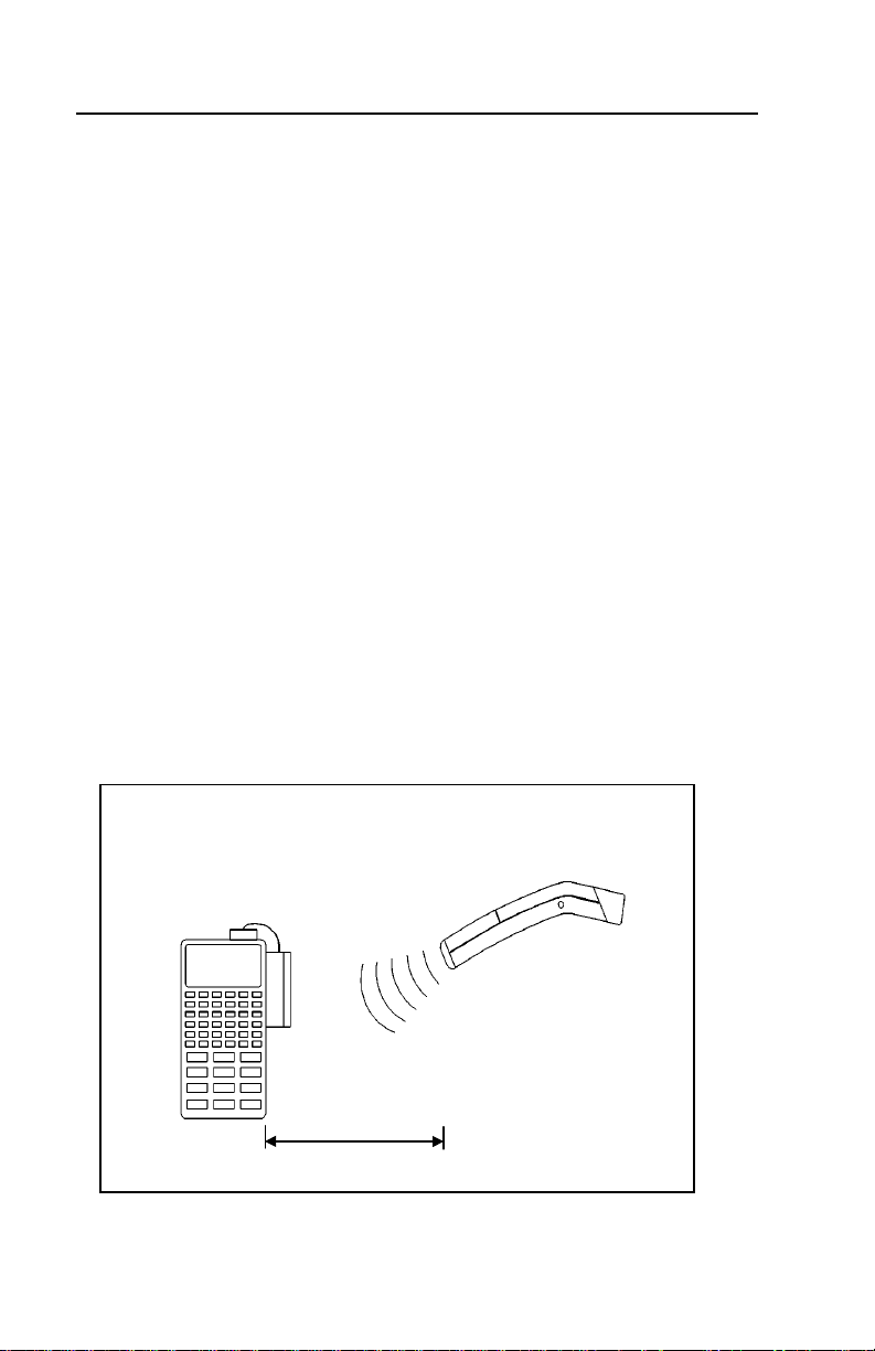
Metrologic’s MX003 Series Scanner Interfaces provide a short range, oneway wireless data communication link between a remote portable scanner
and an RS-232 or light pen host device. Specifically, Metrologic’s MS6130
Hand-Held Laser Scanners include a Liberty
Metrologic’s MS700i/MS720i series scanners, TECH series scanners may
be connected to a MX Series scanner interface. The “MX” scanner interface
includes a RF receiver and a digital interface board.
The MS6130 scanner provides two functions:
• Scans and decodes bar codes
• Transmits scanned data to the RF receiver or “MX”
When the “MX” interface is connected to a ScanPal
a portable data terminal (PDT), it provides two functions
(For example, refer to Figure 1):
• Performs the RF receiver function; for example, beeps to show it has
received data from the transmitter
• Communicates with the host device
In this manual, MX003 series scanner interfaces may be referred to as the
“MX”, “MX” interface or receiver. Suffix of the MX003 model designation will
vary due to country of usage.
®
RF transmitter board.
®
or host device such as
Any RS-232C or
Light Pen Device with
MX003 RF Receiver
2
MS6130 with Liberty® RF
Scanner Interface (Transmitter)
Up to 30 Ft.
(conditions permitting)
Figure 1
Page 9

UNPACKING LIST
Your shipment will contain a set of items from the two groups listed below:
Transmitter Group:
• MS6130 Hand-Held Scanner
• Stand #45880 (optional)
• Stand #45558, 45559 and 45560 (optional)
• MS4120 Programming Guide
Receiver Group:
• “MX” Scanner Interface
• MCA951 adapter or adapter cable (if required)
• Regulated 5V power supply, MLPN: 6090/6091
(115/220 V
• “MX” Scanner Interface
• MS700i with Liberty® RF Receiver option cable
• Power supply (optional)
• Communication cable with connection for power
supply (optional) or communication cable only
• Stand #45483 (optional)
• MS700i and MS720i Installation and User’s Guide
• ScanSelect™ Scanner Programming Guide (#2186)
)(optional)
AC
OR
OR
®
• ScanPal
Data Collector
• “MX” Scanner Interface
• Upload cable, MLPN: 51061 and 51236
• MCA951 adapter
• Regulated 5V power supply, MLPN: 6090/6091 (115/220 V
• ScanPal Data Collector Installation and User’s Guide
AC
)
3
Page 10
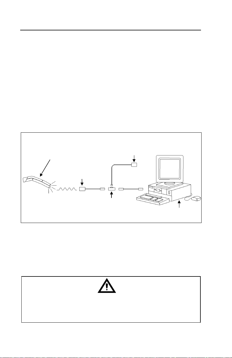
CONNECTIONS OF THE “MX” INTERFACE TO THE HOST DEVICE
Scanne
ace
®
Except version 17
1. Turn off the host system.
2. Connect the MCA to the host device. Connect the “MX” interface to
the MCA.
3. Check the AC input requirements of the transformer to make sure the
voltage matches the AC outlet. The socket outlet should be near the
equipment and easily accessible.
4. Plug the transformer into the side of the MCA and the AC outlet.
5. Power up the host system.
MS6130 with Liberty
Scanner Interface
(Transmitter)
“MX”
Figure 2: Connecting the “MX” (through the MCA) to a host device
To maintain compliance with applicable standards, all circuits connected
to the unit must meet the requirements for SELV (Safety Extra Low
Voltage) according to EN 60950.
RF
r Interf
Transformer
MCA
Host System
4
Page 11
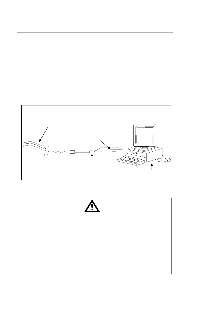
CONNECTIONS OF THE KEYBOARD WEDGE
®
“MX” INTERFACE TO THE PC
Version 17 only
MX003 Scanner Interfaces with a suffix of “17" are Keyboard Wedge
versions used to interface with a PC and keyboard.
1. Turn off the PC.
2. Plug the “MX” receiver adapter cable to the PC keyboard port.
3. Plug the keyboard into the “MX” receiver adapter cable.
4. Power up the PC.
MS6130 with Liberty
Scanner Interface
(Transmitter)
Figure 3: Connecting the “MX” to a PC and keyboard
To maintain compliance with applicable standards, all circuits connected
to the unit must meet the requirements for SELV (Safety Extra Low
Voltage) according to EN 60950.
The following statement is applicable if the scanner will receive power
from a host device such as a computer system.
Caution: To maintain compliance with standards CSA C22.2 No. 950/UL
1950 and norm EN60950, the power source must meet
applicable performance requirements for a limited power
source.
RF
Optional Adapter
“MX” Receiver adapter Cable
Host System
5
Page 12

CONNECTIONS OF THE MS700I/MS720I
“MX” TO THE HOST DEVICE
WITH
To avoid potential problems, do not power up the scanner until the
communication cable is secured to the host.
1. Turn off the host system.
2. Connect the 25-pin D-type connector on the MS700i/MS720i scanner’s
head cable to the communication cable. Connect the other end of the
communication cable to the host device. If the scanner will not receive
power from a transformer, skip to Step 5.
3. If the scanner will receive power from an external power source, check
the AC input requirements of the transformer to make sure the voltage
matches the AC outlet. The socket-outlet should be near the equipment
and easily accessible.
4. Plug the transformer into the side of the female D-type connector
located on the communication cable. Plug the transformer into the AC
outlet to supply power to the scanner.
5. Power up the host system.
6. Attach the “MX” to the MS700i/MS720i scanner via the LSO cable that
terminates to a 10-pin modular connector.
Note: When the MS700i/MS720i scanner firs t rec eives po wer, th e
LEDs will flash and then the scanner will beep once. After the
scanner performs this startup sequence, the green LED will remain
on for a specified time showing that the laser is on.
Refer to the MS700i and MS720i Laser Bar Code Projection
Scanner Installation and User’s Guide for information on how to
operate the scanner.
To maintain compliance with applicable standards, all circuits connected
to the unit must meet the requirements for SELV (Safety Extra Low
Voltage) according to EN 60950.
The following statement is applicable if the scanner will receive power
from a host device such as a computer system.
Caution: To maintain compliance with standards CSA C22.2 No. 950/UL
1950 and norm EN60950, the power source must meet
applicable performance requirements for a limited power
source.
6
Page 13
CONFIGURATION OF THE MS700I/MS720I WITH “MX”
To perform matching procedure refer to page 18.
Once the transmitter is assigned an ID number, configure the S700i/MS720i
to accept RF communication. Although the changes made in this section
effect the receiver, the MS6130 performs all scanning.
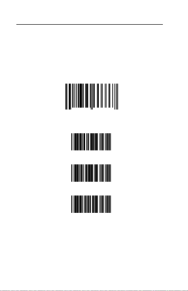
1. Scan the following bar code to enter the receiver’s program mode.
(The MS700i/MS720i will beep three times):
Enter/Exit Program Mode for the Receiver
12345 66666
0
2. Enable the RF interface by scanning the following bar codes in order:
R01
7
LP1
HH1
3. Exit program mode by scanning the bar code in Step 1 again.
4. Proceed to the procedure on the next page.
7
Page 14

CONFIGURATION OF THE MS700I/MS720I WITH “MX”
TO THE HOST SYSTEM
To perform matching procedure refer to page 18.
Before the MS700i/MS720i scanner ships from the factory, the factory
programs the scanner to a group of default settings noted in the
ScanSelect™ Scanner Programming Guide. An asterisk marks each default
setting. The asterisk appears before the brief definition located near the bar
code. Once RF communication establishes, change the default settings of
your scanner to meet your individual scanning needs or your host system’s
communication requirements. Modify the scanner's settings by entering the
program mode and scanning the appropriate bar codes that appear in the
ScanSelect Scanner Programming Guide.
Note: When the Load Defaults bar code in the ScanSelect Scanner
Programming Guide is chosen, it will automatically disable the RF
low speed option. For the MS6130 to communicate to the
MS700i/MS720i scanner, re-enable the RF Low Speed Option (refer
to the procedure above).
8
Page 15

CONFIGURATION OF THE “MX” TO THE SCANPAL
®
DATA COLLECTOR
To perform matching procedure refer to page 18.
The RS-232 parameters marked with an asterisk ( * ) in the charts are the
default settings of the “MX”. The charts are in the Default Settings of the
MS6130 and “MX” Receiver section of this guide. To communicate with
each other properly, the “MX” and ScanPal must have matching RS-232
parameters. However, the Enter/Exit Program Mode bar code in the
MS4120 Programming Guide will not cause your “MX” to enter or exit
program mode. Scan the Enter/Exit Program Mode for the Receiver bar
code in the following procedure.
Before completing RF communication, program the ScanPal to the same
settings as the IBM® PC XT, AT or PS/2 compatible computer. Once
completed and the receiver and MS6130 have the same assigned ID
number, configure the “MX” to the same settings as ScanPal.
1. Program the ScanPal to the same settings as the PC.
(Refer to the Programming the ScanPal section in the ScanPal
Collector Installation and User’s Guide)
2. Scan the following bar code to enter program mode.
(The “MX” receiver will beep three times):
Enter/Exit Program Mode for the Receiver
12345 66666
0
7
3. Scan the appropriate communication options in the MS4120
Programming Guide.
4. Exit program mode by scanning the bar code in Step 1 again.
Note: Scan the Enter/Exit Program Mode for the Receiver bar
code and exit program mode if the PC uses the same
parameters as the default settings of ScanPal.
Default to ScanPal Communication Parameters
IB5
®
Data
9
Page 16

CONFIGURATION OF THE “MX” TO THE RS-232, LIGHT PEN OR
KEYBOARD WEDGE HOST SYSTEM
To perform matching procedure refer to page 18.
The light pen, RS-232 and Keyboard Wedge parameters marked with an
asterisk ( * ) in the charts are the default settings of the “MX”. The charts are
in the Default Settings of the Transmitter and “MX” Receiver section of this
guide. To communicate with a host system properly, program the “MX” to
match the host system’s requirements. However, the Enter/Exit Program
Mode bar code in the MS4120 Programming Guide will not cause your “MX”
to enter or exit program mode. Scan the Enter/Exit Program Mode for the
Receiver bar code in the following procedure. Once the MS6130 is assigned
an ID number, configure the “MX” to the correct communication protocol.
1. Scan the following bar code to enter program mode.
(The “MX” receiver will beep three times):
Enter/Exit Program Mode for the Receiver
12345 66666
0
2. Scan the following bar code to confirm the receiver is using the
original factory settings.
7
Recall Defaults
DF1
3. Scan the appropriate communication options in the MS4120 and
MS951 Programming Guides.
4. Exit program mode by scanning the following bar code.
(The “MX” receiver will beep three times):
Enter/Exit Program Mode for the Receiver
12345 66666
0
7
10
Page 17

KEYBOARD WEDGE (KB) INTERFACE
Scan the ENABLE KB WEDGE INTERFACE bar code if your communication
requirement is keyboard emulation. The scanner will provide keyboard
emulation by converting the scanned bar code data to the PC keyboard scan
code equivalent.
Enable Keyboard Wedge Interface
R24
KB Parameter - Keyboard Type
The following bar codes are used to define the type of keyboard in use. If
necessary, scan the appropriate bar code.
** AT Keyboard (includes IBM
®
PS/2: Models 50, 55, 60, 80)
LP3
XT Keyboard
LP4
Enable IBM PS/2 Keyboard (Models 30, 70, 8556)
SH4
** Disable IBM PS/2 Keyboard (Models 30, 70, 8556)
SH3
Enable Single-Ended Keyboard Emulation
R57
11
Page 18

KEYBOARD WEDGE (KB) INTERFACE (CONTINUED)
KB Parameter – Keyboard Type
The following bar codes are used to define the keyboard country type. If
necessary, scan the appropriate bar code.
** USA Keyboard
BR8
UK Keyboard
BR2
France Keyboard
BR3
Germany Keyboard
BR4
Italy Keyboard
BR5
Spain Keyboard
12
BR6
Belgium Keyboard
BR1
IBM KB4700 Financial Keyboard
BR7
Swiss Keyboard
BR9
Reserved
BRA
Page 19

KEYBOARD WEDGE (KB) INTERFACE (CONTINUED)
Reserved
BRB
Reserved
BRC
Reserved
BRD
Reserved
BRE
Reserved
BRF
KB Parameter - Caps Lock Mode
When Caps Lock is used on the
keyboard, choose ENABLE CAPS
LOCK. Once enabled, the scanner
will simulate Caps
Lock keyboard input. This mode will
not work with all keyboard types.
Enable Caps Lock
R46
**Disable Caps Lock
To detect automatically if Caps Lock
is used, enable AUTO-DETECTION
CAPS LOCK MODE. This will only
work with an AT computer.
R47
Enable Auto Detection
Caps Lock Mode
R68
**Disable Auto Detection
Caps Lock Mode
R69
13
Page 20

KEYBOARD WEDGE (KB) INTERFACE (CONTINUED)
KB Parameter - Alt Mode
When this option is enabled, the scanner will
duplicate this keyboard sequence: Hold down
the Alt key; type the decimal number that
corresponds to the appropriate keyboard
character. Caution should be observed when
using Alt mode because a scanner to host
application conflict may occur if the host
software application uses the Alt key as a
“Hot” key.
KB Parameter - Inter Scan Code Delay (AT and PS/2 Modes)
The time specified with an interscan code
delay bar code represents the amount of time
between individual 9 bit scan codes. Each
character of a bar code takes between two
and twelve of these scan codes to be passed
through to the PC via the keyboard interface.
This parameter may need to be adjusted for
operation with certain PC keyboard BIOS’s.
Network operating systems often use
microprocessor time slices to service network
information requests instead of the keyboard
interface. While not an issue with manually
entered keystrokes, this timing can be critical
with automatic scanner data entry. Interscan
code delays can be a useful system tuning
tool in these environments.
Enable Alt Mode
HH3
**Disable Alt Mode
HH4
** 800 Microsecond Delay
OC8
7.5 Millisecond Delay
OC9
15 Millisecond Delay
KB Parameter - XT - Clean-Up Bit
Some keyboard BIOS's require a "cleanup
bit" to be transmitted before an actual scan
code being clocked over to the motherboard.
Enabling this feature will cause the scanner to
send this extra bit to the host computer. More
commonly found on older XT style BIOS's,
and some AT BIOS's. (required by some NEC
80286 machines).
14
OC7
Enable Cleanup Bit
HH1
** Disable Cleanup Bit
HH2
Page 21

CONFIGURATION OF THE MS6130 HAND-HELD
To perform matching procedure refer to page 18.
Before the MS6130 scanner ships from the factory, the factory programs the
scanners to a set of default settings. These default settings can be found in
the MS4120 Programming Guide. The default settings have an asterisk that
appears before the brief definition located near the bar code. Once RF
communication establishes, change the default settings of your scanner to
meet your individual scanning needs. Configure the scanner by scanning
the Transmitter Enter/Exit Program Mode bar code and the appropriate bar
codes in the MS4120 Programming Guide.
For example, to program the MS6130 not to read ITF
(Interleaved 2 of 5) bar code types:
• With the MS6130, scan the Enter/Exit Program Mode bar code in the
MS4120 Programming Guide, the Disable ITF bar code, then the
Enter/Exit Program Mode bar code again.
Note: When the MS6130 is in program mode, never scan any of the
RS-232 or light pen options marked with an “R”. The list of
options is in the Default Settings of the Transmitter and “MX”
Receiver section of this guide when using the MS4120
Programming Guide. The MS6130 is in program mode when
scanning the Enter/Exit Program Mode bar code in the
MS4120 Programming Guide.
15
Page 22

ENABLING THE MS700I/MS720I SCANNER’S RF LOW SPEED
OPTION
Before beginning this procedure, perform all steps in the sections, Matching
the Transmitter to the Receiver and Configuration of the MS700i/MS720i
with “MX”.
Use the MS700i/MS720i scanner to scan the following bar codes.
1. Temporarily cover the bar code below Step 3. Scan the following bar
code to enter program mode.
(The MS700i scanner will beep three times):
Enter/Exit Program Mode for the Receiver
12345 66666
0
2. Temporarily cover the bar code in Step 1. Scan the Enable RF Low
Speed Option bar code below Step 3.
7
3. Exit program mode by scanning the bar code in Step 1 again.
Enable RF Low Speed Option
12345 12915
0
5
16
Page 23

CHANGING THE ID
In order for the MS6130 to send data to the correct receiver, they must have
a matching ID number. The ID number is the serial number of the receiver.
When the matching procedure is completed, the receiver will accept data
only from a MS6130 that has the matching ID number. Each receiver is
programmed with its serial number before it leaves the factory.
1. To program a new ID for the receiver, HANDSET
(Version 1.14 or greater) must be used. Type the following at the
DOS prompt:
HANDSET /X
2. Power up the receiver, but DO NOT scan any bar codes.
3. Select “Enter Program Mode”. Select the appropriate SERIAL PORT
(COM 1 or COM 2) on the PC. Make sure the Receiver is connected
to the SERIAL PORT selected.
4. Select “Get Scanners Settings”. A screen will appear showing all of
the options available.
5. Using the arrow keys, move down to the section labeled “Metro ID#”.
Locate the serial number on the case of the receiver. Enter this 10digit number into the “Metro ID#” section.
6. Press the “F5" key to program the receiver.
7. The receiver will beep when programming is completed. The receiver
is now programmed with its proper ID. Exit HANDSET by pressing
“F9" and then press “7".
8. Power Down the receiver.
17
Page 24

MATCHING PROCEDURE
With the MS6130, scan the following bar codes starting from the top down:
Transmitter Enter/Exit Program Mode
**
Recall Defaults
DF1
Enable RF Communications
R35
Transmitter Enter/Exit Program Mode
**
Locate the model label on the case of the receiver. Scan the serial number
bar code.
The receiver and MS6130 are now matched.
For information on how to configure the receiver, refer to the appropriate
section in this guide.
Note: If using more than one MS6130 with one receiver, perform the
above procedure for each MS6130. Since each MS6130 has the
same ID number, the receiver will accept data from all of the
scanners
18
Page 25

PARTS OF TH E MS6130 HAND-HELD BAR CODE SCANNER
r
y
Becoming familiar with the features of the MS6130 hand-held scanner will
help when operating one of these scanners. The illustration and list explain
the pertinent parts.
Green and Red LED
Replaceable
Pack
Batter
Output
Window
Infra-red (IR)
Senso
Reactivation
Switch
Battery Charge
Figure 4: Scanner Parts
Battery Charge Contacts Receptacle for the battery charger.
Reactivation Switch Turns the unit on after a timeout. Press the
button from the bottom.
Green and Red LEDs When the red LED is on, the laser is on. If the
green LED flashes on, the scanner has read a
bar code successfully. Communication to the
host is complete when the receiver beeps.
Infrared Object Sensor When a specified time has elapsed without any
scanning, the unit will enter a “standby” mode.
To reactivate the unit, remove the current
object and present an object in front of the
output window again.
Output Window This aperture emits laser light.
19
Page 26

COMPONENT S OF TH E MS6130 SERIES STAND
The following are the components used to build the MS6130 series stand
(MLPN: 45880).
1
1. Cradle
2. Stand Charger Pack
3. Pole Cover
4. Flex pole
5. Stand Base Cover
6. Stand Base
7. Charger Transformer
8. Charger Pack Screws
9. Mounting Screws
10. Lock Washer
2
10
8
3
4
5
CABLE
CONNECTS
THROUGH
OPENING
7
9
20
6
Figure 5: Scanner Parts
Page 27

INSTALLATION O F THE M S6130 SERIES STAND
Refer to for numbered components on the previous page
1. Use the stand base (6) as a template to drill and mount the base to the
counter using the mounting screws (9) provided.
2. Feed the wire from the transformer (7) through the slot in the base cover
(5) approximately 9" of the wire.
3. Press the base cover (5) over the base (6).
4. Attach the flex pole (4) to the base (6).
5. Slide the flex cover (3) over the pole (4) and wire.
6. Attach the cradle (1) to the flex pole (4) using the lock washer (10) to
connect the transformer.
7. Insert the transformer plug into the connector inside the stand charger
pack (2).
8. Clip the charger pack to the bottom of the cradle (1) lock in place using
two screws (8).
Stand LED Indicators (with the scanner in the stand)
No LED indicates trickle charge and the green LED indicates fast charge. To
change from trickle charge to fast charge, simply lift the scanner from the
stand and replace.
Note: When both scanner LEDs blink, it is an indication of a
low battery.
21
Page 28

INSTALLATION O F THE 6000 SERIES UNIVERSAL CHARGING STAND
MLPN: 45558 - 115V, 45559 - 230V and 45560 - 240V (UK)
Transformer
Green LED
(Charge Status)
Red LED
(Power)
Figure 6: Universal Charging Stand
PERMANENT COUNTER TOP INSTALLATION
1. Separate weighted base from rotating base by removing the (4) four
screws.
2. Use the rotating base as a drill template.
3. Use the (4) four wood screws provided to mount the base to the counter
top securely.
4. Snap the cup assembly to the base.
Note: For non-permanent installation, snap the cup assembly onto the
weighted base
CHARGE STATE CHARGE LED STATUS
Battery Absent LED off
Charge Pending
Fast-Charge LED on
Charge Complete and Top-Off
LED on for 0.125sec,
off for 1.375sec
LED on for 0.125 sec,
off for 0.125sec
22
Page 29

NICD BATTERY CHARGER WITH RECONDITIONING FEATURE
(
)
MLPN: 45561 - 115V and 45562 - 230V
How to Recondition
Transformer
Discharge
Cycle Switch
1. Place the scanner into the
charge stand.
2. Push the stand tilt cup in
the extreme down position
to expose the hole for the
discharge cycle switch.
3. Use a pin to push the
Red LED
Power
Green LED
(Charge Status)
discharge cycle switch
located beneath the hole.
4. When the discharge mode
is initiated the green LED
Figure 7: Reconditioning
flashes.
RECOMMENDED USE
To maintain charge capacity, the NiCd batterie s mus t be disch arged fully
before charging. We call this process reconditioning.
Recondition if:
• The batteries were not used within 20 days
• The batteries were not discharged (approximately two hours of
continuous operation) at least once a week
• Low battery indicators:
• Both LED’s on the scanner blink
• The scanner quietly beeps twice while scanning
Recondition once a week if:
• The batteries do not get discharged for more than 20%
(approximately ½ hour) of their capacity before recharging.
Recondition once every two weeks if:
• The batteries do not get discharged for more than 50%
(approximately 1 hour) of their capacity before recharging.
Note: The day to day usage of the NiCd batteries will determine the
frequency of the discharges (reconditionin g).
Charge State CHG LED Status
Battery Absent LED off
Charge Pending
Discharge-BeforeCharge
Fast-Charge LED on
Charge Complete Top-
Off
LED on for 0.125sec, off for
1.375sec
LED on for 1.375sec, off for
0.125sec
LED on for 0.125 sec, off for
0.125sec
23
Page 30
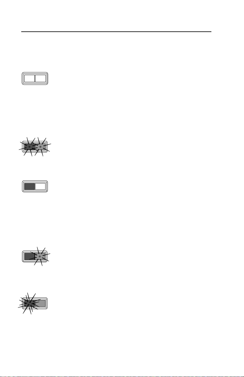
VISUAL INDICATORS
The scanner has red and green LEDs. When the scanner is on, the LEDs
indicate the status of the scan and scanner.
No Red or Green The scanner will turn off if the scanner has
been dormant for a specified time. To
reactivate the unit, direct the output window
up then down toward the bar coded product.
If the unit has been dormant for longer than
10 minutes, reactivating the unit by pressing
the button on the side of the MS6130 will be
necessary.
Red Flash; Green Flash; When the scanner first receives power, the
steady red LED will flash, followed by the
green LED.
Steady Red When the laser is on, the red LED will also be
on. This occurs when an object is in the scan
field. If the scanner does not detect a bar
code within approximately 2.5 seconds, the
red LED will shut off indicating that the laser is
no longer on. If the red LED remains on for
longer than 7.5 seconds, then the scanner is
in program mode.
Steady Red; Green Flash When the scanner successfully reads a bar
code, the green LED will flash. If the green
LED does not flash, then the bar code read
was not successful.
Repetitive Red Flashes When the red LED flashes several times while
it lays upon a stationary surface, then an
object is within the scan field and is activating
the IR sensor. This can occur even while the
scanner is lying upon the counter or cradle.
To eliminate this disturbance, direct the scan
window toward a different location.
24
Page 31

AUDIBLE INDICATORS
When the scanner and “MX” receiver are in operation, they provide audible
indications. These sounds indicate the status of the scan and scanner.
One Beep When the “MX” Receiver first receives power, the unit will
beep once.
If the scanner successfully reads a bar code, the green
light will flash. If the “MX” receiver successfully receives
the data from the MS6130, the “MX” will beep once.
Razzberry Tone If, upon power up, the scanner emits a razzberry tone,
then the scanner has failed diagnostics.
The “MX” receiver will emit a razzberry tone if an invalid
bar code is scanned while the receiver is in program
mode.
The “MX” receiver can be programmed to emit a
razzberry tone when the timeout occurs during
communication between the host and receiver.
Refer to the MS4120 Programming Guide section,
Audible Indicators for Communication Timeouts to
program this feature.
Two Beeps The MS6130 scanner will quietly beep twice when
scanning a bar code if the batteries become low.
Three Beeps When scanning the MS6130 Enter/Exit Program Mode
bar code in the MS4120 Programming Guide, the green
LED will flash three times while the scanner
simultaneously beeps three times. When exiting the
program mode, the same visual and audible indications
will occur. After this sequence is completed, the red LED
will turn off. When scanning the Enter/Exit Program Mode
for the Receiver bar code, the “MX” receiver will beep
three times to indicate it is in or exiting out of the program
mode.
(continued next page)
25
Page 32

AUDIBLE INDICATORS (CONTINUED)
The “MX” receiver can be programmed to emit three
beeps when the timeout occurs during communication
between the host and receiver. Refer to the MS4120
Programming Guide section, Audible Indicators for
Communication Timeouts to program this feature.
There are four settings available for the tone of the beep for the receiver.
Refer to the MS4120 Programming Guide section, Beeper Tones to program
the feature to change the tone or turn the beeper off.
26
Page 33

LABELS
The MS6130 scanner is either a CDRH Class II laser system or an IEC
Class 1 Laser System. Your unit will have a CDRH Class II caution label or
LASERKLASSE 1 label affixed below the model number label. The model
number/avoid exposure label is located on the bottom of the scanner’s head.
The following are examples of these labels:
MAINTENAN CE
Smudges and dirt can interfere with the proper scanning of a bar code.
Therefore, the output window will need occasional cleaning.
1. Spray glass cleaner onto lint free, non-abrasive cleaning cloth.
2. Gently wipe the output window.
27
Page 34

TROUBLESHOOT ING
1. The receiver can receive data from a MS6130 with its own ID or 10
zeroes. It’s own ID can be received all the time. When using 10
zeroes, the first scan the receiver gets must have 10 zeroes as its ID
and from that point on the receiver will accept both ID’s.
Power down the receiver. Using the MS6130, scan the bar codes from
section 9 in the Matching MS6130 to the Receiver section and use the
following bar code as the ID number.
Scanner ID Number
0000000000
Note: Use this bar code for troubleshooting purposes only.
2. Power up the receiver.
3. If the user is trying to match a new ID to the receiver and the receiver is
powered up, the receiver will beep 3 times if the ID number it receives
matches its current ID.
4. When the MS6130 is in program mode, never scan any of the RS-232
or light pen options marked with an “R”. The list of options is in the
Default Settings of the MS6130 and “MX” Receiver sect ion of this gui de
when using the MS4120 Programming Guide. The MS6130 is in
program mode when scanning the Enter/Exit Program Mode bar code
in the MS4120 Programming Guide. If a receiver option is chosen while
the MS6130 is in program mode, RF communication between the
MS6130 and receiver may terminate. If this occurs, the only way to
reestablish RF communication is by performing all the RF configuration
procedures again.
28
Page 35

APPENDIX A
Specifications
RF Link Characteristics
Frequencies: One of the following depending on the
country of operation:
418 MHz
434 MHz
912 MHz
Bandwidth: 220 kHz
Modulation: FM
Certification: No FCC licensing required
RF Protocol: One way data transmission
Transmission time at a maximum of 100 ms
50K baud data rate
Dedicated transmitter(s) to receiver link
Operating Range: Up to 30 feet (conditions permitting)
Specifications subject to change without notice
MS6130 Bar Code Scanner Specifications
UL Listed: US and Canada
FCC ID: LW5613 (912 MHz only)
RF Output Power: 20 uW max. (912 MHz only)
Current: Supplied by rechargeable/replace abl e
batteries
Antenna: Integral
Dimensions:
Length 216 mm [8.5”]
Width 63 mm [2.5”] Head and 48 mm [1.9”] Handle
Height 28 mm [1.1”]
Weight: 289 g [10.5 oz]
Maximum Radiant Power: 0.9 mW Peak
VLD Wavelength: 630 nm to 680 nm
29
Page 36

APPENDIX A (CONTINUED)
MX003 Series Scanner Interface Specifications
FCC ID: LW5003
Operating Voltage: 5Vdc
Antenna: Integral
Dimensions: 90 mm [3.54"] x 50 mm [1.97"] x 24 mm [0.94"]
Weight: 80.3 g [2.8 oz]
UL Listed: US and Canada
Model Number
MX003 912 MHZ
MX003-17 912 MHZ
MX0033 418 MHZ
MX0033-17 418 MHZ
MX0034 434 MHZ
MX0034-17 434 MHZ
Model designation may include the suffix “J” used to indicate the addition of
an audio signal output jack.
Operating
Frequency
Data Interface
RS-232
Light Pen
✓
✓
✓
Data Interface
Keyboard
Wedge
✓
✓
✓
30
Page 37

APPENDIX A (CONTINUED)
Specifications of Battery Pack
Battery Type: “AA” NiCd Rechargeable
Configuration: 3 Batteries/Pack
Nominal Voltage: 3.6 VDC
Maximum Voltage: 4.8 VDC
Capacity: 600 mA
Charge Cycles: Over 500 Full Charge/Discharge
Charge Time: 4 Hours
Short Circuit Protection: Auto/Reset Fuse 1.7A Hold Current
Temperature Characteristics (Degrees Celsius) of each Cell:
Charge: 0 to +45
Discharge: -20 to +60
Storage (Long): -30 to +35
UK Compliance
To charge the batteries in the MS6130 - 418MHz, remove the ESD cover
from the bottom of the unit. Refer to the battery charge rate for additional
information. After a full charge, replace the cover over the battery contacts.
The cover should remain in place during operation
31
Page 38

APPENDIX B
Default Settings of the MS6130 and “MX” Receiver
Before the MS6130 hand-held scanner and “MX” Receiver ships from the
factory, the factory programs the scanners to a group of default settings. An
asterisk ( * ) in the charts on the following pages marks the default settings
of the units. If an asterisk is not in the default column then the default setting
is Off or Disabled.
The MS6130 and “MX” receiver do not support every parameter. For those
parameters that are a transmitter function, a letter “T” will appear in the
second column of the charts, for the “MX”, the
letter “R”.
RS-232, light pen and keyboard wedge emulation does not support every
parameter. If your host device’s communication supports a parameter listed
in the charts on the following pages, a check mark will appear.
In order for the “MX” receiver to communicate with your RS-232, light pen or
keyboard wedge host device properly, program it to meet your individual
scanning needs. Since each host system is unique, change the default
settings to match your host system requirements. To modify default settings,
refer to the MS4120 and MS951 Programming Guides.
Note: If your “MX” Interface is connected to a MS700i/MS720i scanner,
use the bar codes in the ScanSelect Programming Guide to match
your scanner’s settings to the host system requirements.
T - Transmitter (MS6130 Hand-held)
R - Receiver (“MX”)
Parameter
Enter/Exit Program Mode T
Recall Defaults R
Enter Program Mode After Any
Scan T *
Enter Program Mode Only on
First Scan T
Short Range Activation Out of the
Stand T
Long Range Activation Out of the
Stand T *
Short Range Activation in the
Stand
T - Transmitter
R - Receiver
T
32
Default RS-232
✓✓
✓✓
✓✓
✓✓
✓✓
Light
Pen
Page 39

APPENDIX B (CONTINUED)
Parameter
Long Range Activation in the
Stand T *
Normal Scan T * ✓✓
Pulsing Scan T ✓✓
Custom Scan T ✓✓
Green LED Rescan Indicator T ✓✓
Short Same Symbol Rescan T
Long Same Symbol Rescan T *
Alternate Beeper Tone 1 R ✓✓
Alternate Beeper Tone 2 R * ✓✓
Alternate Beeper Tone 3 R
No Beeper Tone R
Two Second Time-out R
No Two Second Timeout R * ✓
Razzberry Tone on Timeout R ✓
No Tone on Timeout R * ✓
Three Beeps on Timeout R ✓
Beep Before Transmit R * ✓
Beep After Transmit R ✓
Baud Rate R 960 0 ✓
Parity R Space ✓
8 Data Bits R
7 Data Bits R *
RTS/CTS R
Character RTS/CTS R * ✓
Message RTS/CTS R ✓
ACK/NAK R ✓
XON/XOFF R ✓
No Intercharacter Dela y R * ✓
1 Millisecond Intercharacter
Delay R
5 Millisecond Intercharacter
Delay R
25 Millisecond Intercharacter
Delay R
T - Transmitter
R - Receiver
Default RS-232
✓✓
✓✓
✓✓
✓✓
✓✓
✓
✓
✓
✓
✓
✓
✓
Light
Pen
33
Page 40

APPENDIX B (CONTINUED)
Parameter
DTR Input R ✓
Carriage Return R * ✓
Line Feed R *
ETX Suffix R
Tab Prefix R
Tab Suffix R ✓
Prefix ID for UPC/EAN R ✓
Suffix ID for UPC/EAN R
Bars High R * ✓
Spaces High R
Transmit as Scanned R *
Transmit as Code 39 R
Poll Light Pen 5 Volts R
No Poll Light Pen R * ✓
UPC T * ✓✓
EAN T * ✓✓
Code 39 T * ✓✓
Codabar T * ✓✓
Code 128 T * ✓✓
Code 93 T * ✓✓
Interleaved 2 of 5 (ITF) T * ✓✓
MSI Plessey Decode T
Enable Code 11 Decode T
Enable Airline 2 of 5 T
Full ASCII Code 39 T ✓✓
Italian Pharmaceutical R ✓✓
Minimum 1 Character Code
Length T
Minimum 3 Character Code
Length T *
Minimum 6 Character Code
Length T
T - Transmitter
R - Receiver
Default RS-232
✓
✓
✓
✓
✓✓
✓✓
✓✓
✓✓
✓✓
✓✓
Light
Pen
✓
✓
✓
✓
34
Page 41

APPENDIX B (CONTINUED)
y
y
PARAMETER
Keyboard Type R
AT R *
XT R ✓
PS2 R
Keyboard Country Type R
USA R * ✓
UK R
France R
German
Italy R
Spain R
Belgium R ✓
KB4700 R
Swiss R
Caps Lock R ✓
Autodetection R
User Defined R
Transmit Cleanup Bit
Transmit Alt Mode
Transmit 0F0H Break
Character
Inter Scan Code Dela
0R
800 msec R *
7.5 msec R ✓
15 msec R
Intercharacter Delay
0R✓
1 msec R
10 msec R *
100 msec R * ✓
Stand Alone Scanner Mode R
T - TRANSMITTER
R - RECEIVER
R ✓
R
R
R*
R ✓
R
DEFAULT
KEYBOARD
WEDGE
✓
✓
✓
✓
✓
✓
✓
✓
✓
✓
✓
✓
✓
✓
✓
✓
✓
✓
✓
✓
✓
✓
35
Page 42

APPENDIX C
MX003 Series Scanner Interface Pin Assignments
The interfaces are equipped with a shielded, 10-pin modular jack
manufactured by Steward Stamping. The mating connector is a Steward
Stamping shielded plug #937-SP-361010. Caution should be used when
working with cables for this port because there is typically power present for
scanner interface operation.
Models MX003, MX0033 and MX0034:
Pin Function
1 Power (d/c)/Shield Ground
2 RS-232 Transmit Output
3 RS-232 Receiver Input
4 RTS Output
5 CTS Input
6 DTR Input
7LP/DATA
8NC
9 +5Vdc Power to Scanner Interface
10 NC
Models MX003-17, MX0033-17 and MX0034-17:
Pin Function
1 Power (d/c)/Shield Ground
2 RS-232 Transmit Output
3 RS-232 Receiver Input
4 Keyboard Data
5 Keyboard Clock
6 PC Clock
7 PC Data
8NC
9 PC +5V/ External +5V
10 NC
36
Page 43

APPENDIX D
Warranty and Disclaimer
Limited Warranty
The MS6130 scanners are manufactured by Metrologic at its Blackwood, New Jersey,
U.S.A. facility. The MS6130 scanners have a two (2) year limited warranty from the
date of manufacture. Metrologic warrants and represents that all MS6130 scanners
are free of all defects in material, workmanship and design, and have been produced
and labeled in compliance with all applicable U.S. Federal, state and local laws,
regulations and ordinances pertaining to their production and labeling.
This warranty is limited to repair, replacement of Product or refund of Product price at
the sole discretion of Metrologic. Faulty equipment must be returned to the Metrologic
facility in Blackwood, New Jersey, U.S.A. or Puchheim, Germany. To do this, contact
Metrologic’s Customer Service/Repair Departm ent t o obtain a Returned Materi al
Authorization (RMA) number.
In the event that it is determined the equipment failure is covered under this
warranty, Metrologic shall, at its sole option, repair the Product or replace the
Product with a functionally equivalent unit and return such repaired or replaced
Product without charge for service or return freight, whether distributor,
dealer/reseller, or retail consumer, or refund an amount equal to the original
purchase price.
This limited warranty does not extend to any Product which, in the sole judgement
of Metrologic, has been subjected to abuse, misuse, neglect, improper installation,
or accident, nor any damage due to use or misuse produced from integration of the
Product into any mechanical, electrical or computer system. The warranty is void if
the case of Product is opened by anyone other than Metrologic’s repair department
or authorized repair centers.
THIS LIMITED WARRANTY, EXCEPT AS TO TITLE, IS IN LIEU OF ALL OTHER
WARRANTIES OR GU AR AN TEES, EITHER EXPRESS OR IMPLIED, AND
SPECIFICALLY EXCLU DES, WITH OU T LIMIT ATIO N, WARRAN TIES OF
MERCHANTABILITY AND FITNESS F O R A PART ICULAR PURPOSE UNDER
THE UNIFORM COMMERCIAL CODE, OR ARISING OUT OF CUSTOM OR
CONDUCT. THE RIGHTS AND REMEDIES PROVIDED HEREIN ARE
EXCLUSIVE AND IN LIEU OF ANY OTHER RIGHTS OR REMEDIES. IN NO
EVENT SHALL METROLOGIC BE LIABLE FOR ANY INDIRECT OR
CONSEQUENTIAL DAMAGES, INCIDENTAL DAMAGES, DAMAGES TO
PERSON OR PROPERTY, OR EFFECT ON BUSINESS OR PROPERTY, OR
OTHER DAMAGES OR EXPENSES DUE DIRECTLY OR INDIRECTLY TO THE
PRODUCT, EXC EPT AS STATED IN THIS WAR R AN TY. IN NO EVENT SHALL
ANY LIABILITY OF METROLOGIC EXCEED THE ACTUAL AMOUNT PAID TO
METROLOGIC FOR THE PRODUCT. METROLOGIC RESERVES THE RIGHT
TO MAKE ANY CHANGES TO THE PRODUCT DESCR IBED HEREIN.
North America Headquarters
Metrologic Instruments, Inc. Customer Service: 1-800-ID-METRO
90 Coles Road Tel: 856-228-8100
Blackwood, NJ 08012-4683 Email: info@metrologic.com
Website: www.metrolo gic.com
Germany
Metrologic Instruments GmbH Tel: 49-89-89019-0
Dornierstrasse 2 Fax: 49-89-89019-200
82178 Puchheim b. Email: info@europe.metrologic.com
Munich, Germany
37
Page 44

APPENDIX E
Notices
Caution
Use of controls or adjustments or performance of procedures other than those specified
herein may result in hazardous laser light exposure. Under no circumstances shoul d
the customer attempt to service the laser scanner. Never attempt to look at the laser
beam, even if the scanner appears to be nonfunctional. Never open the scanner in an
attempt to look into the device. Doing so could result in hazardous laser light exposure.
The use of optical instruments with the laser equipment will increase eye hazard.
Atención
La modificación de los procedimientos, o la utilización de controles o ajustes distint os
de los especificados aquí, pueden provocar una luz de láser peligrosa. Bajo ninguna
circunstancia el usuario deberá realizar el mantenimiento del láser del escáner. Ni
intentar mirar al haz del láser incluso cuando este no esté operativo. Tampoco deberá
abrir el escáner para examinar el aparato. El hacerlo puede conllevar una exposición
peligrosa a la luz de láser. El uso de instrumentos ópticos con el equipo láser puede
incrementar el riesgo para la vista.
Attention
L'emploi de commandes, réglages ou procédés autres que ceux décrits ici peut
entraîner de graves irradiations. Le client ne doit en aucun cas essayer d'entretenir
lui-même le scanner ou le laser. Ne regardez jamais directement le rayon laser,
même si vous croyez que le scanner est inactif. N'ouvrez jamais le scanner pour
regarder dans l'appareil. Ce faisant, vous vous exposez à une rayonnement laser qú
êst hazardous. L'emploi d'appareils optiques avec cet équipement laser augm ente l e
risque d'endommagement de la vision.
Achtung
Die Verwendung anderer als der hier beschriebenen Steuerungen, Einstellungen oder
Verfahren kann eine gefährliche Laserstrahlung hervorrufen. Der Kunde sollte unter
keinen Umständen versuchen, den Laser-Scanner selbst zu warten. Sehen Sie
niemals in den Laserstrahl, selbst wenn Sie glauben, daß der Scanner nicht aktiv ist.
Öffnen Sie niemals den Scanner, um in das Gerät hineinzusehen. Wenn Sie dies tun,
können Sie sich einer gefährlichen Laserstrahlung aussetzen. Der Einsat z optischer
Geräte mit dieser Laserausrüstung erhöht das Risiko einer Sehschädigung.
Attenzione
L’utilizzo di sistemi di controllo, di regolazioni o di procedimenti di versi da quelli
descritti nel presente Manuale può provocare delle esposizioni a raggi laser rischios e.
Il cliente non deve assolutamente tentare di riparare egli stesso lo scanner las er. Non
guardate mai il raggio laser, anche se credete che lo scanner non sia attivo. Non
aprite mai lo scanner per guardare dentro l’apparecchio. Facendolo potete esporVi ad
una esposizione laser rischiosa. L’uso di apparecchi ottici, equipaggiati con raggi
laser, aumenta il rischio di danni alla vista.
Notice - applicable to 912 MHz devices only
This device complies with part 15 of the FCC Rules. Operation is subject to the
following two conditions: (1) This device may not cause harmful interference, and (2)
this device must accept any interference received, including interference that may
cause undesired operation. Any unauthorized changes or modifications to this
equipment could void the users authority to operate this device.
Notice - applicable to 912 MHz devices when used in Canad
Operation is subject to the following two conditions: (1) this device may not cause
interference, and (2) this device must accept any interference, incl udi ng interference
that may cause undesired operation of the device.
a
38
Page 45

APPENDIX F
Patents
“Patent Information
This METROLOGIC product may be covered by one or more of the following
U.S. Patents:
U.S. Patent No. 4,930,848; 4,958,984; 5,081,342; 5,260,553; 5,340,971;
5,340,973; 5,424,525; 5,468,951; 5,484,992; 5,525,789; 5,528,024;
5,591,953; 5,616,908; 5,627,359; 5,661,292; 5,777,315; 5,789,730;
5,789,731; 5,808,285; 5,811,786; 5,825,012; 5,886,337; 5,925,870;
5,925,871; 5,929,419; 5,939,701; 5,979,766; 6,015,019; 6,029,894;
D315,901;
4,360,798; 4,369,361; 4,387,297; 4,460,120; 4,496,831; 4,593,186;
4,607,156; 4,673,805; 4,736,095; 4,758,717; 4,816,660; 4,845,350;
4,896,026; 4,923,281; 4,933,538; 4,992,717; 5,015,833; 5,017,765;
5,059,779; 5,117,098; 5,124,539; 5,130,520; 5,132,525; 5,140,144;
5,149,950; 5,180,904; 5,200,599; 5,229,591; 5,247,162; 5,250,790;
5,250,791; 5,250,792; 5,262,628; 5,280,162; 5,280,164; 5,304,788;
5,321,246; 5,324,924; 5,340,971; 5,340,973; 5,396,053; 5,396,055;
5,408,081; 5,410,139; 5,436,440; 5,449,891; 5,468,949; 5,479,000;
5,532,469; 5,545,889; 5,874,721;
No license right or sublicense is granted, either expressly or by implication,
estoppel, or otherwise, under any METROLOGIC or third party intellectual
property rights (whether or not such third party rights are licensed to
METROLOGIC), including any third party patent listed above, except for an
implied license only for the normal intended use of the specif ic equ ipm ent,
circuits, and devices represented by or contained in the METROLOGIC
products that are physically transferred to the user, and only to the extent of
METROLOGIC’s license rights and subject to any conditions, covenants and
restrictions therein.”
Other worldwide patents pending.
39
Page 46

INDEX
A
AC 4, 6
Adapter 3
Asia ii
Audible indicators 25, 26
B
Battery pack 31
Beep(s) 1, 2, 6, 7, 9, 10, 16
17, 19, 23, 25, 26, 28
C
Cable 3, 6
Changing ID 17
Clean 27
Clean-up bit 14
Compliance 4, 6, 31
Configuration(s) 7-10, 15, 16, 28
Connections 4, 6
Copyright ii
Current 29
Customer Service ii
D
Default settings 32-35
Dimensions 29
Disclaimer 37
E
Email ii
ESD 31
Europe ii
External power source 6
I
ID 7, 9, 10, 17, 18, 28
Indicators 21, 23-25
Installation
Stand 21, 22
Internet ii
K
Keyboard wedge 10-14, 29
L
Labels 27
LASERKLASSE 1 27
LEDs 1, 6, 19, 21-25
®
Liberty
, 16, 29
List 3
Locations ii
Low speed options 8, 16
interface 1-3, 7, 9, 10
M
Maintenance 27
Matching procedure 18
MCA95 13
Model number 27
MS6130 1-3, 7-10, 15, 17-21
24, 25, 27-29, 31, 32
MS700i/MS720i 1, 6-8, 32
“MX” 2-10, 15, 16, 25, 26, 28, 32
N
NiCd battery charger 23, 31
Notices 38
F
Fax ii
Function(s) 2
G
Germany (GmbH) ii
Green LED 6, 19, 21, 23-25
H
Headquarters ii
Host 4, 6, 8, 10, 14, 32
40
O
Output window 19, 24, 27
P
Parts 19
Patents 40
Programming guide 3, 8-10
15,25, 26, 28, 32
Page 47

INDEX (CONTINUE D)
R
Receiver board 2
Red LED 1, 19, 24, 25
Rights property 40
RS-232 9, 10, 28
S
ScanPal
ScanSelect 3, 8, 32
Shipping carton 3
South America ii
Specifications 29-31
Stand 3, 20-23
®
2, 3, 9
T
Temperature 31
Tones 26
Transformer 4, 6, 20, 21
Transmitter 1-3, 7, 10, 15,
16, 18, 29, 32-35
Troubleshooting 28
U
Unpacking list 3
USA corporate headquarters ii
V
Visual indicators 24
Voltage 4-6, 29, 31
W
Weight 29
Window 1, 19, 24, 27
41
Page 48

March 2002
Printed in the USA
00-02212
 Loading...