

Page 1

Dell EMC ML3 Tape Library
User's Guide
Page 2

Information in this document is subject to change without notice.
Copyright © 2020 Dell Inc. or its subsidiaries. All rights reserved.
Dell, EMC, and other trademarks are trademarks of Dell Inc. or its subsidiaries. Other trademarks
may be trademarks of their respective owners.
Printed September 2020.
ii
Dell EMC ML3 Tape Library: User's Guide
Page 3

Read this FIRST
Regulatory information
• The library must be installed in a restricted area.
• Only personnel with technical and product safety training should have access to the library.
• The library must be properly installed in an ofce or industrial environment with shielded cables and
adequate grounding of SAS interface and input power to comply with regulations and standards.
• Models: 3555-L3A, 3555-E3A
The system complies to all applicable safety standards to allow for shipments worldwide including the
America's, European Union Member States, Middle East, and Asia.
Minimum rmware levels for common library features
Table 1. Minimum rmware levels for common library features
Feature Minimum Firmware Levels Required
LTO8 (HH/FH) Tape Drives Library Firmware must be at 1.1.1.0 or greater to
support the LTO8 tape drives. Ensure that any host
applications and device drivers are at the minimum
level that is required to support LTO8 tape drives.
Certain non-IBM LTO8 media requires minimum
drive rmware J4D4. Contact your media supplier
for details.
LTO6 (HH/FH) and LTO7 (HH/FH) Tape Drives Library Firmware must be at 1.1.0.1-A00 or greater
to support the LTO6 and LTO7 tape drives. Ensure
that any host applications and device drivers are at
the minimum level that is required to support LTO6
and LTO7 tape drives.
Library-Managed Encryption Library Firmware must be at 1.1.1.0-A00 or greater
to support the Library-Managed Encryption feature.
Ensure that any key manager applications are at
the minimum level that is required to support the
3U library.
SKLM for z/OS encryption requires minimum library
rmware 1.2.0.0-B00.
Path Failover (Control Path and Data Path) Library Firmware must be at 1.1.1.0-A00 or greater
to support the Path Failover feature. Ensure that
any device drivers are at the minimum level that is
required to support the 3U library.
Remote Logging (rsyslog) Library Firmware must be at 1.1.1.0-A00 or greater
to support the Remote Logging feature. Ensure that
any device drivers are at the minimum level that is
required to support the 3U library.
Page 4

Table 1. Minimum rmware levels for common library features (continued)
Feature Minimum Firmware Levels Required
LTO M8 media
Sequential Mode Library Firmware must be at 1.1.1.2-A00 or greater
Library Serial Number 7800K0K or greater Library rmware must be at 1.2.1.0-A00 or greater
Key Path Diagnostics (KPD) Library Firmware must be at 1.3.0.0-A00 or greater
Contacting Dell
For customers in the United States, call 800-WWW-DELL (800-999-3355).
Note: If you do not have an active Internet connection, you can nd contact information about your
purchase invoice, packing slip, bill, or Dell product catalog.
Library Firmware must be at 1.1.1.1-B00 or greater
to support the M8 media feature. Drive rmware
must be at HB82 or greater to support the M8
media feature. Ensure that any device drivers are
at the minimum level that is required to support
the 3U library.
to support Sequential Mode. Ensure that any host
applications are at the minimum level that is
required to support the 3U library in this mode.
to support newer library serial numbers.
to support KPD.
Dell provides online and telephone-based support and service options. Service availability varies by
country and product, and some services might not be available in your area. To contact Dell for sales,
technical support, or customer service issues follow the steps that are listed:
1. Go to www.Dell.com/support.
2. Select your country from the drop-down menu on the lower right corner of the page.
3. For customized support:
a. Enter your system Service Tag in the Enter your Service Tag eld.
b. Click Submit. The support page that lists the various support categories is displayed.
4. For general support:
a. Select your product category.
b. Select your product segment.
c. Select your product. The support page that lists the various support categories is displayed.
5. For contact details of Dell Global Technical Support:
a. Click Global Technical Support.
b. The Contact Technical Support page is displayed with details to call, chat, or e-mail the Dell
Global Technical Support team.
iv
Dell EMC ML3 Tape Library: User's Guide
Page 5

Contents
............................................................................................................................. ii
Read this FIRST....................................................................................................iii
Minimum rmware levels for common library features............................................................................. iii
Contacting Dell............................................................................................................................................ iv
Figures................................................................................................................. ix
Tables................................................................................................................ xiii
Safety and environmental notices ........................................................................xx
Danger and Caution notices....................................................................................................................... xx
Possible safety hazards............................................................................................................................xxv
Class I laser product.................................................................................................................................xxv
Acclimation.............................................................................................................................................. xxvi
Performing the safety inspection procedure.......................................................................................... xxvi
Rack safety...............................................................................................................................................xxvi
Power Cords..............................................................................................................................................xxx
Preface.............................................................................................................xxxi
Chapter 1. Overview.............................................................................................. 1
Introduction................................................................................................................................................. 1
Structure and supported library congurations..........................................................................................2
Components............................................................................................................................................6
User interfaces...........................................................................................................................................11
Supported tape drives............................................................................................................................... 11
Control path drives...............................................................................................................................12
Mixed drives..........................................................................................................................................12
Drive sled back panels......................................................................................................................... 13
Physical and logical addresses of drives............................................................................................. 15
Supported tape cartridges.........................................................................................................................16
Library functions........................................................................................................................................ 16
Random and Sequential Logical Library modes.................................................................................. 16
Encryption.............................................................................................................................................17
Library sharing......................................................................................................................................18
Control path failover, Data path failover, and load balancing.............................................................18
Alerts and logging.................................................................................................................................19
Host connectivity....................................................................................................................................... 20
Network connectivity.................................................................................................................................21
Chapter 2. Planning............................................................................................. 22
Library Layout and Location requirements............................................................................................... 22
Power cords............................................................................................................................................... 27
Network requirements...............................................................................................................................32
Host requirements.....................................................................................................................................32
Chapter 3. Installing............................................................................................34
Unpacking the Base Module and Expansion Modules.............................................................................. 36
v
Page 6

Identifying Library Module components................................................................................................... 40
Preparing top and bottom modules.......................................................................................................... 40
Installing modules in a rack...................................................................................................................... 43
Installing a tabletop module..................................................................................................................... 47
Aligning and connecting modules............................................................................................................. 47
Validating tape drive installation...............................................................................................................50
Connecting cables......................................................................................................................................51
Powering on the library..............................................................................................................................52
The Initial Setup process...........................................................................................................................53
Initial conguration and customization.................................................................................................... 54
Labeling and loading tape cartridges........................................................................................................ 54
Verifying the installation............................................................................................................................56
Advanced library conguration................................................................................................................. 56
Overview...............................................................................................................................................56
Library partitioning............................................................................................................................... 57
Verifying the host connection....................................................................................................................58
Chapter 4. Managing............................................................................................59
The Management GUI................................................................................................................................59
The Operator Panel....................................................................................................................................62
Locating Management functions............................................................................................................... 63
Default settings.................................................................................................................................... 67
Methods of cleaning drives.................................................................................................................. 70
Accessing cartridges............................................................................................................................ 71
Conguring Library Managed Encryption.............................................................................................72
Chapter 5. Troubleshooting..................................................................................75
Finding event information..........................................................................................................................75
Identifying a failed component................................................................................................................. 75
Running library tests..................................................................................................................................75
Troubleshooting Guide.............................................................................................................................. 75
Pre-call checklist....................................................................................................................................... 79
Contacting Dell...........................................................................................................................................80
Diagnostic information...............................................................................................................................80
The ITDT rmware update, dump retrieval and drive test tool ......................................................... 80
Event codes.......................................................................................................................................... 81
TapeAlert Flags.................................................................................................................................. 105
Sense data..........................................................................................................................................111
Drive Error Codes: Single-character display (SCD)........................................................................... 111
Chapter 6. Upgrading and servicing....................................................................115
Internal view of library............................................................................................................................ 115
Adding, removing, or replacing a tape drive........................................................................................... 116
Adding or replacing a Base or Expansion Module.................................................................................. 120
Adding, removing, or replacing a power supply..................................................................................... 125
Replacing a Base or Expansion controller card...................................................................................... 128
Installing, removing, or replacing an accessor and spooling mechanism............................................. 131
Returning the accessor to the Base Module......................................................................................137
Removing or replacing a spooling mechanism....................................................................................... 138
Removing or replacing a magazine......................................................................................................... 142
Moving the library modules.....................................................................................................................143
vi
Appendix A. Library Conguration Forms........................................................... 146
Library information.................................................................................................................................. 146
Module and drive information................................................................................................................. 148
Logical Library information......................................................................................................................149
Users account information...................................................................................................................... 150
Page 7

Appendix B. Management GUI functions and roles ............................................. 151
Appendix C. LTO media......................................................................................157
Data cartridges........................................................................................................................................ 157
Cartridge Read/Write compatibility...................................................................................................158
LTO Type M Cartridge (M8)................................................................................................................ 158
WORM (Write Once, Read Many) cartridges........................................................................................... 159
WORM media......................................................................................................................................159
Data security on WORM media.......................................................................................................... 160
WORM media errors...........................................................................................................................160
Cleaning cartridge....................................................................................................................................160
Labeling tape cartridges..........................................................................................................................160
Guidelines for bar code labels........................................................................................................... 162
Write-Protect switch................................................................................................................................162
Handling the cartridges........................................................................................................................... 163
Providing training............................................................................................................................... 163
Ensuring proper packaging................................................................................................................ 164
Proper acclimation and environmental conditions........................................................................... 164
Completing a thorough inspection.................................................................................................... 165
Handling the cartridge carefully........................................................................................................ 165
Environmental and shipping specications for tape cartridges.............................................................166
Appendix D. REST API for scalable tape libraries................................................167
Resources................................................................................................................................................ 169
System................................................................................................................................................169
Library information.............................................................................................................................171
Library operations.............................................................................................................................. 179
Library conguration.......................................................................................................................... 183
Library test......................................................................................................................................... 187
Drive information................................................................................................................................190
Drive conguration.............................................................................................................................190
Partition (Logical Library) information...............................................................................................192
Partition (Logical Library) conguration............................................................................................ 197
Denitions................................................................................................................................................198
BaseInfoData..................................................................................................................................... 198
BaseStatusData..................................................................................................................................199
DriveInfo.............................................................................................................................................200
Error....................................................................................................................................................201
EventEntry.......................................................................................................................................... 202
IOStatus............................................................................................................................................. 202
Inventory............................................................................................................................................ 202
LibraryInfo..........................................................................................................................................203
LibraryStatus...................................................................................................................................... 203
LicenseInfo.........................................................................................................................................203
MediaInfoData....................................................................................................................................203
Module................................................................................................................................................204
ModuleStatusData..............................................................................................................................205
Modules..............................................................................................................................................205
PartitionInfo....................................................................................................................................... 205
Slot......................................................................................................................................................207
TestStatus.......................................................................................................................................... 208
Security.................................................................................................................................................... 208
Appendix E. Accessibility...................................................................................210
Glossary............................................................................................................211
vii
Page 8

Index................................................................................................................ 231
viii
Page 9

Figures
1. Two module tape library............................................................................................................................... 1
2. Base Module ................................................................................................................................................. 2
3. Expansion Module......................................................................................................................................... 3
4. Base Module.................................................................................................................................................. 3
5. 2 module library............................................................................................................................................ 3
6. 3 module library............................................................................................................................................ 3
7. 4 module library............................................................................................................................................ 4
8. 5 module library............................................................................................................................................ 4
9. 6 Module library.............................................................................................................................................5
10. 7 module library.......................................................................................................................................... 6
11. Front panel ..................................................................................................................................................7
12. Rear panel....................................................................................................................................................8
13. Physical numbering of modules .................................................................................................................9
14. Left magazine.............................................................................................................................................. 9
15. Right magazine..........................................................................................................................................10
16. Power supply rear panel LEDs..................................................................................................................11
17. Mixed drives in a logical library.................................................................................................................13
18. Drive sled indicators..................................................................................................................................13
19. Half-height SAS dual port......................................................................................................................... 14
20. Half-height FC single port.........................................................................................................................14
21. Full-height FC dual port............................................................................................................................ 14
22. Physical numbering of drives....................................................................................................................15
ix
Page 10

23. Psychrometric chart showing recommended and allowable operating environments for the tape
library..........................................................................................................................................................25
24. Types of receptacles.................................................................................................................................31
25. Removing the module from the box......................................................................................................... 37
26. The module after removal from the box...................................................................................................37
27. Unlatching the top of the module.............................................................................................................38
28. Removing the top of the module.............................................................................................................. 38
29. The module is opened to show the foam packing................................................................................... 39
30. The foam packing is removed, and the internal components are shown - Base Module.......................39
31. Lowering the front of the top cover.......................................................................................................... 41
32. Unlocking the spring loaded lock............................................................................................................. 42
33. Removing the cover.................................................................................................................................. 42
34. Lifting the cover and locking it..................................................................................................................43
35. Universal rack connector.......................................................................................................................... 43
36. Incorrect connector locations ................................................................................................................. 44
37. Correct connector locations .....................................................................................................................44
38. Mounting the rails to the connectors........................................................................................................45
39. Side rails installed.....................................................................................................................................46
40. Sliding the library into the rack.................................................................................................................46
41. Library in the rack......................................................................................................................................47
42. Hole for alignment pin...............................................................................................................................48
43. Alignment lever lock................................................................................................................................. 48
44. Alignment lever locked or engaged to lower module.............................................................................. 49
45. Alignment lever unlocked or disengaged.................................................................................................49
46. Two modules in rack, seen from the rear.................................................................................................50
47. Connected modules.................................................................................................................................. 50
x
Page 11

48. Full-height FC dual port............................................................................................................................ 51
49. Half-height FC single port.........................................................................................................................51
50. Half-height SAS dual port......................................................................................................................... 52
51. IP address selection................................................................................................................................. 53
52. Open I/O station seen from the left..........................................................................................................55
53. Magazine pulled out..................................................................................................................................55
54. Management GUI main screen................................................................................................................. 60
55. Operator Panel main screen..................................................................................................................... 62
56. Front panel LEDs....................................................................................................................................... 63
57. Internal view of the library..................................................................................................................... 115
58. Drive bay covers......................................................................................................................................117
59. Alignment rails........................................................................................................................................ 117
60. Installing a tape drive............................................................................................................................. 118
61. Unlocking the drive................................................................................................................................. 118
62. Interconnect cables................................................................................................................................122
63. Unlocking or disengaging the alignment lever.......................................................................................123
64. Loosening the thumbscrews.................................................................................................................. 124
65. Sliding the module out of the rack......................................................................................................... 124
66. Power supplies........................................................................................................................................126
67. Sliding in the new power supply.............................................................................................................127
68. Controller card components...................................................................................................................129
69. Installing a Controller card.....................................................................................................................130
70. Magazine release levers......................................................................................................................... 132
71. Unlocking the robot................................................................................................................................ 133
72. Finger holes.............................................................................................................................................133
xi
Page 12

73. Unlocking the spooling cable and placing it in its cradle.......................................................................134
74. Spooling cable in park position.............................................................................................................. 134
75. Pins are aligned horizontally.................................................................................................................. 135
76. Installing the spooling cable.................................................................................................................. 136
77. Inserting the screwdriver to manually operate the accessor................................................................137
78. Left magazine opening............................................................................................................................138
79. Unlocking the spooling mechanism....................................................................................................... 139
80. Unlocked spooling mechanism - enlarged view.................................................................................... 140
81. Locked spooling mechanism - enlarged view........................................................................................141
82. Removing the spooling mechanism....................................................................................................... 142
83. Manually releasing the right magazine...................................................................................................143
84. Manually releasing the left magazine.....................................................................................................143
85. The LTO data cartridge........................................................................................................................... 157
86. LTO Data and WORM tape cartridges.....................................................................................................160
87. Sample bar code label on the LTO8 Tape Cartridge.............................................................................. 162
88. Setting the write-protect switch.............................................................................................................163
89. Double-boxing tape cartridges for shipping...........................................................................................164
90. Checking for gaps in the seams of a cartridge....................................................................................... 165
xii
Page 13

Tables
1. Minimum rmware levels for common library features...............................................................................iii
2. Module designations..................................................................................................................................... 1
3. Minimum and maximum storage congurations..........................................................................................2
4. Library congurations....................................................................................................................................3
5. Front panel descriptions............................................................................................................................... 7
6. Rear panel descriptions.................................................................................................................................8
7. Physical numbering of storage slots - bottom module.............................................................................. 10
8. Power supply LEDs......................................................................................................................................11
9. Supported tape drives.................................................................................................................................12
10. Drive sled indicators..................................................................................................................................13
11. Half-height SAS dual port......................................................................................................................... 14
12. Half-height FC single port.........................................................................................................................14
13. Full-height FC dual port............................................................................................................................ 15
14. Differences between CPF and DPF...........................................................................................................19
15. Location requirements..............................................................................................................................22
16. Physical specications..............................................................................................................................23
17. Electrical specications for one module (base or expansion).................................................................23
18. Equipment environment specications for the tape library.................................................................... 24
19. Gas and particulate exposure...................................................................................................................26
20. Power cords...............................................................................................................................................27
21. Installation Precautions............................................................................................................................35
22. Full-height FC dual port............................................................................................................................ 51
23. Half-height FC single port.........................................................................................................................51
xiii
Page 14

24. Half-height SAS dual port......................................................................................................................... 52
25. Main screen elements...............................................................................................................................60
26. Navigation Dock........................................................................................................................................ 61
27. Status icons...............................................................................................................................................61
28. Operator Panel menu tree........................................................................................................................ 62
29. Front panel LEDs ...................................................................................................................................... 63
30. Locating Management functions.............................................................................................................. 63
31. Default settings......................................................................................................................................... 67
32. Magazine state.......................................................................................................................................... 71
33. Resolving errors........................................................................................................................................ 76
34. Main error events...................................................................................................................................... 82
35. Warning events..........................................................................................................................................91
36. Conguration Change events..................................................................................................................102
37. Informational Events.............................................................................................................................. 103
38. Error codes on the single-character display.......................................................................................... 112
39. Meaning of Status light and single-character display (SCD)................................................................. 113
40. Internal view description........................................................................................................................115
41. Pinch hazard............................................................................................................................................116
42. Power supply components..................................................................................................................... 126
43. Controller card components...................................................................................................................129
44. Management GUI functions and roles....................................................................................................151
45. Cartridge data capacity and recording formats..................................................................................... 157
xiv
46. Nominal cartridge life: Load/unload cycles........................................................................................... 158
47. Data cartridge compatibility with LTO tape drive.................................................................................. 158
48. LTO Cartridge Types............................................................................................................................... 158
Page 15

49. Cartridges and VOLSERs compatible with the LTO Tape Drives........................................................... 161
50. Location of the write-protect switch...................................................................................................... 163
51. Environment for storage and shipping the LTO tape cartridges............................................................166
52. General REST API information............................................................................................................... 167
53. Synonyms................................................................................................................................................168
54. Product Variants......................................................................................................................................168
55. Responses...............................................................................................................................................169
56. Response 200......................................................................................................................................... 169
57. Parameters..............................................................................................................................................170
58. User......................................................................................................................................................... 170
59. Responses...............................................................................................................................................170
60. Response 201......................................................................................................................................... 170
61. Responses...............................................................................................................................................171
62. Security................................................................................................................................................... 171
63. Parameters..............................................................................................................................................172
64. Responses...............................................................................................................................................173
65. Security................................................................................................................................................... 173
66. Responses...............................................................................................................................................173
67. Security................................................................................................................................................... 174
68. Responses...............................................................................................................................................175
69. Security................................................................................................................................................... 176
70. Responses...............................................................................................................................................176
71. Security................................................................................................................................................... 177
72. Responses...............................................................................................................................................177
73. Security................................................................................................................................................... 177
xv
Page 16

74. Responses...............................................................................................................................................178
75. Security................................................................................................................................................... 178
76. Responses...............................................................................................................................................179
77. Security................................................................................................................................................... 179
78. Parameters..............................................................................................................................................180
79. Module.....................................................................................................................................................180
80. Responses...............................................................................................................................................180
81. Security................................................................................................................................................... 180
82. Parameters..............................................................................................................................................181
83. Elements................................................................................................................................................. 181
84. Responses...............................................................................................................................................181
85. Security................................................................................................................................................... 181
86. Parameters..............................................................................................................................................182
87. RoboticPos.............................................................................................................................................. 182
88. Responses...............................................................................................................................................182
89. Security................................................................................................................................................... 182
90. Responses...............................................................................................................................................183
91. Security................................................................................................................................................... 183
92. Parameters..............................................................................................................................................183
93. mailslotConf............................................................................................................................................183
94. Responses...............................................................................................................................................184
95. Security................................................................................................................................................... 184
xvi
96. Parameters..............................................................................................................................................184
97. LicenseKey.............................................................................................................................................. 184
98. Responses...............................................................................................................................................184
Page 17

99. Security................................................................................................................................................... 185
100. Parameters............................................................................................................................................185
101. ManufacturingMode..............................................................................................................................185
102. Responses.............................................................................................................................................185
103. Security................................................................................................................................................. 185
104. Parameters............................................................................................................................................186
105. SerialNumber........................................................................................................................................186
106. Responses.............................................................................................................................................186
107. Security................................................................................................................................................. 186
108. Parameters............................................................................................................................................187
109. Responses.............................................................................................................................................187
110. Security................................................................................................................................................. 187
111. Parameters............................................................................................................................................187
112. count..................................................................................................................................................... 188
113. Responses.............................................................................................................................................188
114. Security................................................................................................................................................. 188
115. Responses.............................................................................................................................................188
116. Security................................................................................................................................................. 189
117. Parameters............................................................................................................................................189
118. testParameter.......................................................................................................................................189
119. Responses.............................................................................................................................................189
120. Security................................................................................................................................................. 190
121. Responses.............................................................................................................................................190
122. Security................................................................................................................................................. 190
123. Parameters............................................................................................................................................191
xvii
Page 18

124. Responses.............................................................................................................................................191
125. Security................................................................................................................................................. 191
126. Parameters............................................................................................................................................191
127. DriveNumber.........................................................................................................................................192
128. Responses.............................................................................................................................................192
129. Security................................................................................................................................................. 192
130. Responses.............................................................................................................................................192
131. Security................................................................................................................................................. 193
132. Parameters............................................................................................................................................194
133. Responses.............................................................................................................................................194
134. Security................................................................................................................................................. 194
135. Parameters............................................................................................................................................196
136. Responses.............................................................................................................................................196
137. Security................................................................................................................................................. 196
138. Parameters............................................................................................................................................197
139. partitionParameters..............................................................................................................................197
140. Responses.............................................................................................................................................198
141. Security................................................................................................................................................. 198
142. BaseInfoData........................................................................................................................................199
143. BaseStatusData.................................................................................................................................... 200
144. BaseInfoData........................................................................................................................................200
145. Error...................................................................................................................................................... 201
xviii
146. EventEntry.............................................................................................................................................202
147. IOStatus................................................................................................................................................202
148. Inventory...............................................................................................................................................202
Page 19

149. LibraryInfo............................................................................................................................................ 203
150. LibraryStatus.........................................................................................................................................203
151. LicenseInfo........................................................................................................................................... 203
152. MediaInfoData...................................................................................................................................... 203
153. Module.................................................................................................................................................. 205
154. ModuleStatusData................................................................................................................................ 205
155. PartitionInfo..........................................................................................................................................205
156. Slot........................................................................................................................................................ 207
157. TestStatus.............................................................................................................................................208
xix
Page 20

Safety and environmental notices
When this product is used, observe the danger, caution, and attention notices that are contained in this
guide. The notices are accompanied by symbols that represent the severity of the safety condition.
The sections that follow dene each type of safety notice and give examples.
Danger and Caution notices
Danger notices
A danger notice calls attention to a situation that is potentially lethal or extremely hazardous to people. A
lightning bolt symbol always accompanies a danger notice to represent a dangerous electrical condition.
xx Dell EMC ML3 Tape Library: User's Guide
Page 21
To prevent a possible shock from touching two surfaces with different
protective ground(earth), use one hand, when possible, to connect or
disconnect signal cables. (D001)
Overloading a branch circuit is potentially a re hazard and a shock
hazard under certain conditions. To avoid these hazards, ensure that your
system electrical requirements do not exceed branch circuit protection
requirements. Refer to the information that is provided with your device
or the power rating label for electrical specications. (D002)
If the receptacle has a metal shell, do not touch the shell until you have
completed the voltage and grounding checks. Improper wiring or
grounding could place dangerous voltage on themetal shell. If any of the
conditions are not as described, STOP. Ensure the improper voltage or
impedance conditions are corrected before proceeding.(D003)
An electrical outlet that is not correctly wired could place hazardous
voltage on the metal parts of the system or the devices that attach to the
system. It is the responsibility of the customer to ensure that the outlet is
correctly wired and grounded to prevent an electrical shock.(D004)
When working on or around the system, observe the following
precautions:
Electrical voltage and current from power, telephone, and
communication cables are hazardous. To avoid a shock hazard:
• If Dell supplied a power cord(s), connect power to this unit only with
the Dell provided power cord. Do not use the Dell provided power cord
for any other product.
• Do not open or service any power supply assembly.
• Do not connect or disconnect any cables or perform installation,
maintenance, or reconguration of this product during an electrical
storm.
• The product might be equipped with multiple power cords. To remove
all hazardous voltages, disconnect all power cords.
– For AC power, disconnect all power cords from their AC power
source.
– For racks with a DC power distribution panel (PDP), disconnect the
customer’s DC powersource to the PDP.
• When connecting power to the product ensure all power cables are
properly connected.
– For racks with AC power, connect all power cords to a properly wired
and grounded electrical outlet. Ensure that the outlet supplies
proper voltage and phase rotation according to the system rating
plate.
– For racks with a DC power distribution panel (PDP), connect the
customer’s DC power source to the PDP. Ensure that the proper
polarity is used when attaching the DC power and DC power return
wiring.
• Connect any equipment that will be attached to this product to properly
wired outlets.
Safety and environmental notices
xxi
Page 22
• When possible, use one hand only to connect or disconnect signal
cables.
• Never turn on any equipment when there is evidence of re, water, or
structural damage.
• Do not attempt to switch on power to the machine until all possible
unsafe conditions are corrected.
• Assume that an electrical safety hazard is present. Perform all
continuity, grounding, and power checks specied during the
subsystem installation procedures to ensure that the machine meets
safety requirements.
• Do not continue with the inspection if any unsafe conditions are
present.
• Before you open the device covers, unless instructed otherwise in the
installation and conguration procedures: Disconnect the attached AC
power cords, turn off the applicable circuit breakers located in the rack
power distribution panel (PDP), and disconnect any
telecommunications systems, networks, and modems.
• Connect and disconnect cables as described in the following
procedures when installing, moving, or opening covers on this product
or attached devices.
To disconnect:
1. Turn off everything (unless instructed otherwise).
2. For AC power, remove the power cords from the outlets.
3. For racks with a DC power distribution panel (PDP), turn off the circuit
breakers located in the PDP and remove the power from the
Customer's DC power source.
4. Remove the signal cables from the connectors.
5. Remove all cables from the devices.
To connect:
1. Turn off everything (unless instructed otherwise).
2. Attach all cables to the devices.
3. Attach the signal cables to the connectors.
4. For AC power, attach the power cords to the outlets.
5. For racks with a DC power distribution panel (PDP), restore the power
from the Customer'sDC power source and turn on the circuit breakers
located in the PDP.
6. Turn on the devices.
• Sharp edges, corners and joints may be present in and around the
system. Use care when handling equipment to avoid cuts, scrapes and
pinching. (D005)
Heavy equipment - personal injury or equipment damage might result if
mishandled. (D006)
xxii Dell EMC ML3 Tape Library: User's Guide
Page 23
Uninterruptible power supply (UPS) units contain specic hazardous
materials. Observe the following precautions if your product contains a
UPS:
• The UPS contains lethal voltages. All repairs and service must be
performed only by an authorized service support representative. There
are no user serviceable parts inside the UPS.
• The UPS contains its own energy source (batteries). The output
receptacles might carry live voltage even when the UPS is not
connected to an AC supply.
• Do not remove or unplug the input cord when the UPS is turned on. This
removes the safety ground from the UPS and the equipment connected
to the UPS.
• The UPS is heavy because of the electronics and batteries that are
required. To avoid injury,observe the following precautions:
– Do not attempt to lift the UPS by yourself. Ask another service
representative for assistance.
– Remove the battery, electronics assembly, or both from the UPS
before removing the UPS from the shipping carton or installing or
removing the UPS in the rack.
(D007)
Professional movers are to be used for all relocation activities. Serious
injury or death might occur if systems are handled and moved incorrectly.
(D008)
Ensure that your DC mains supply is earthed at the point of generation
per IEC 60950-1and ITU-T Recommendation K.27. (D009)
Serious injury or death can occur if loaded lift tool falls over or if a heavy
load falls off the lift tool. Always completely lower the lift tool load plate
and properly secure the load on the lift tool before moving or using the
lift tool to lift or move an object. (D010)
DANGER: Multiple power cords. The product might be equipped
with multiple AC power cords or multiple DC power cables. To
remove all hazardous voltages, disconnect all power cords and
power cables. (L003)
Caution notices
A caution notice calls attention to a situation that is potentially hazardous to people because of some
existing condition, or to a potentially dangerous situation that might develop because of some unsafe
practice.
The doors and covers to the product are to be closed at all times except
for service by trained service personnel. All covers must be replaced and
doors closed at the conclusion of the service operation. (C013)
This product is equipped with a 3-wire (two conductors and ground)
power cable and plug. Use this power cable with a properly grounded
electrical outlet to avoid electrical shock. (C018)
This assembly contains mechanical moving parts. Use care when
servicing this assembly. (C025)
Safety and environmental notices xxiii
Page 24
A caution notice can be accompanied by one of several symbols:
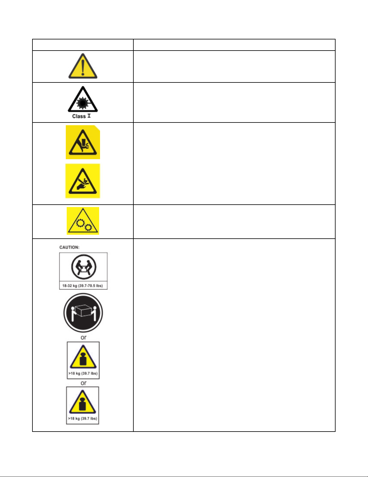
If the symbol is... It means...
A generally hazardous condition not represented by other safety
symbols.
A hazardous condition due to the use of a laser in the product. Laser
symbols are always accompanied by the classication of the laser as
dened by the U. S. Department of Health and Human Services (for
example, Class I, Class II, and so forth).
Risk of hand pinching, can trap hands, ngers and cause serious injury.
Keep hands clear during operation (L012).
Caution: moving parts. (L037)
The weight of this part or unit is between 18 and 32 kg (39.7 and 70.5
lb). It takes two persons to safely lift this part or unit. (C009)
xxiv Dell EMC ML3 Tape Library: User's Guide
Page 25
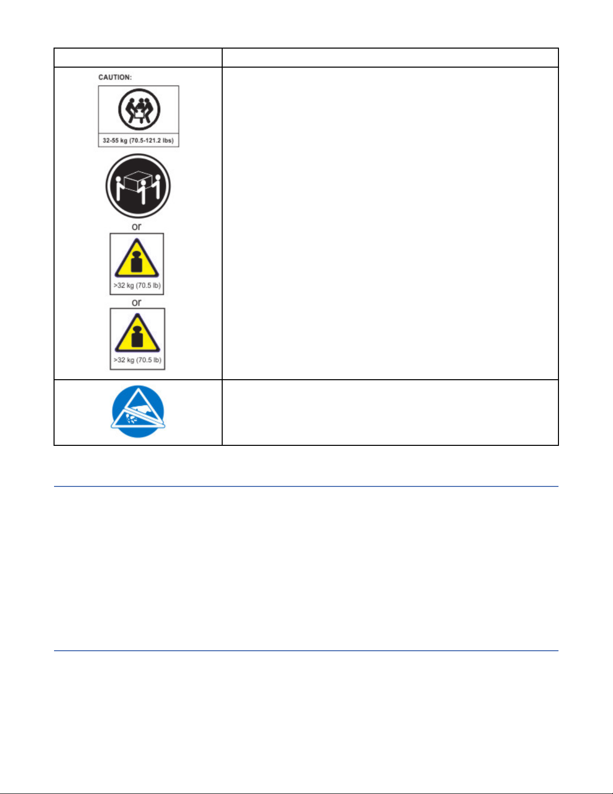
If the symbol is... It means...
The weight of this part or unit is between 32 and 55 kg (70.5 and 121.2
lb). It takes three persons to safely lift this part or unit. (C010)
Possible safety hazards
Possible safety hazards to the operation of this product are:
Electrical
An electrically charged frame can cause serious electrical shock.
Mechanical
Hazards (for example, a safety cover missing) are potentially harmful to people.
Chemical
Do not use solvents, cleaners, or other chemicals that are not approved for use on this product.
Before the library is used, repair any of the preceding problems.
Class I laser product
Before the library is used, review the following laser safety information.
A hazardous condition due to the unit's susceptibility to electrostatic
discharge.
The product might contain a laser assembly that complies with the performance standards set by the US
Food and Drug Administration for a Class I laser product. Class I laser products do not emit hazardous
laser radiation. The product has the necessary protective housing and scanning safeguards to ensure that
laser radiation is inaccessible during operation or is within Class I limits. External safety agencies
reviewed the product and obtained approvals to the latest standards as they apply.
Safety and environmental notices
xxv
Page 26

Acclimation
Server and storage equipment (racks and frames) must be gradually acclimated to the surrounding
environment to prevent condensation.
When server and storage equipment (racks and frames) is shipped in a climate where the outside
temperature is below the dew point of the destination (indoor location), there’s a possibility that water
condensation can form on the cooler inside and outside surfaces of the equipment when the equipment is
brought indoors.
Sufcient time must be allowed for the shipped equipment to gradually reach thermal equilibrium with
the indoor environment before you remove the shipping bag and energize the equipment. Follow these
guidelines to properly acclimate your equipment:
• Leave the system in the shipping bag. If the installation or staging environment allows it, leave the
product in the full package to minimize condensation on or within the equipment.
• Allow the packaged product to acclimate for 24 hours.1 if there are visible signs of condensation (either
external or internal to the product) after 24 hours, acclimate the system without the shipping bag for an
extra 12 - 24 hours or until no visible condensation remains.
• Acclimate the product away from perforated tiles or other direct sources of forced air convection to
minimize excessive condensation on or within the equipment.
1
Unless otherwise stated by product-specic installation instructions.
Note: Condensation is a normal occurrence, especially when you ship equipment in cold-weather
climates. All Dell products are tested and veried to withstand condensation that is produced under these
circumstances. When sufcient time is provided to allow the hardware to gradually acclimate to the
indoor environment, there should be no issues with long-term reliability of the product.
Performing the safety inspection procedure
Before you service the unit, complete the following safety inspection procedure.
1. Stop all activities between the host and the library’s tape drives.
2. Turn off the power to the library by pushing in the Power button on the front of the tape library for 4
seconds.
3. Unplug the library’s power cord from the electrical outlet and the library’s power supply unit.
4. Check the library’s power cords for damage, such as a pinched, cut, or frayed cord.
5. If drives are FC/SAS attached, check the tape drive's FC/SAS cable for damage.
6. Check the top and bottom covers of the library for sharp edges, damage, or alterations that expose its
internal parts.
7. Check the top and bottom covers of the library for proper t. They must be in place and secure.
8. Check the product label at the rear of the library to make sure that it matches the voltage at your
outlet.
Rack safety
The following general safety information must be used for all rack-mounted devices.
DANGER
xxvi
Dell EMC ML3 Tape Library: User's Guide
Page 27
Observe the following precautions when working on or around your IT rack system.
• Heavy equipment - personal injury or equipment damage might result if mishandled.
• Always lower the leveling pads on the rack cabinet.
• Always install stabilizer brackets on the rack cabinet.
• To avoid hazardous conditions due to uneven mechanical loading, always install the heaviest devices in
the bottom of the rack cabinet. Always install servers and optional devices starting from the bottom of
the rack cabinet.
• Rack-mounted devices are not to be used as shelves or work spaces. Do not place objects on top of
rack-mounted devices. In addition, do not lean on rack mounted devices and do not use them to
stabilize your body position (for example, when working from a ladder).
• Each rack cabinet might have more than one power cord.
– For AC powered racks, be sure to disconnect all power cords in the rack cabinet when directed to
disconnect power during servicing.
– For racks with a DC power distribution panel (PDP), turn off the circuit breaker that controls the
power to the system unit(s), or disconnect the customer’s DC power source, when directed to
disconnect power during servicing.
• Connect all devices installed in a rack cabinet to power devices installed in the same rack cabinet. Do
not plug a power cord from a device installed in one rack cabinet into a power device installed in a
different rack cabinet.
• An electrical outlet that is not correctly wired could place hazardous voltage on the metal parts of the
system or the devices that attach to the system. It is the responsibility of the customer to ensure that
the outlet is correctly wired and grounded to prevent an electrical shock. (R001 part 1 of 2)
Caution
• Do not install a unit in a rack where the internal rack ambient temperatures might exceed the
manufacturer's recommended ambient temperature for all your rack-mounted devices.
• Do not install a unit in a rack where the air flow is compromised. Ensure that air flow is not blocked or
reduced on any side, front, or back of a unit that is used for air flow through the unit.
• Consideration must be given to the connection of the equipment to the supply circuit so that
overloading of the circuits does not compromise the supply wiring or overcurrent protection. To provide
the correct power connection to a rack, refer to the rating labels on the equipment in the rack to
determine the total power requirement of the supply circuit.
• (For sliding drawers) Do not pull out or install any drawer or feature if the rack stabilizer brackets are
not attached to the rack. Do not pull out more than one drawer at a time. The rack might become
unstable if you pull out more than one drawer at a time.
Safety and environmental notices
xxvii
Page 28
• (For xed drawers) This drawer is a xed drawer and must not be moved for servicing unless specied
by the manufacturer. Attempting to move the drawer partially or out of the rack might cause the rack to
become unstable or cause the drawer to fall out of the rack. (R001 part 2 of 2)
Caution
Removing components from the upper positions in the rack cabinet improves rack stability during
relocation. Follow these general guidelines whenever you relocate a populated rack cabinet within a room
or building:
• Reduce the weight of the rack cabinet by removing equipment, starting at the top of the rack cabinet.
When possible, restore the rack cabinet to the conguration of the rack cabinet as you received it. If this
conguration is not known, you must do the following:
– Remove all devices in the 32U position (compliance ID RACK-001) or 22U (compliance ID RR001)
and above.
– Ensure that the heaviest devices are installed in the bottom of the rack cabinet.
– Ensure that there are little-to-no empty U-levels between devices installed in the rack-cabinet below
the 32U (compliance ID RACK-001) or 22U (compliance ID RR001) level, unless the received
conguration specically allowed it.
• If the rack cabinet you are relocating is part of a suite of rack cabinets, detach the rack cabinet from the
suite.
• If the rack cabinet you are relocating was supplied with removable outriggers, they must be reinstalled
before the cabinet is relocated.
• Inspect the route that you plan to take to eliminate potential hazards.
• Verify that the route that you choose can support the weight of the loaded rack cabinet. Refer to the
documentation that comes with your rack cabinet for the weight of a loaded rack cabinet.
• Verify that all door openings are at least 760 x 2032 mm (30 x 80 in.).
• Ensure that all devices, shelves, drawers, doors, and cables are secure.
• Ensure that the four leveling pads are raised to their highest position.
• Ensure that no stabilizer bracket is installed on the rack cabinet during movement.
• Do not use a ramp that is inclined at more than 10 degrees.
• When the rack cabinet is in the new location, complete these steps.
– Lower the four leveling pads.
– Install stabilizer brackets on the rack cabinet or in an earthquake environment bolt the rack to the
floor.
– If you removed any devices from the rack cabinet, repopulate the rack cabinet from the lowest
position to the highest position.
xxviii
Dell EMC ML3 Tape Library: User's Guide
Page 29
• If a long-distance relocation is required, restore the rack cabinet to the conguration of the rack cabinet
as you received it. Pack the rack cabinet in the original packaging material, or equivalent. Also, lower the
leveling pads to raise the casters off the pallet and bolt the rack cabinet to the pallet. (R002)
•
Caution
• Rack is not intended to serve as an enclosure and does not provide any degrees of protection required
of enclosures.
• It is intended that equipment installed within this rack will have its own enclosure. (R005)
• Tighten the stabilizer brackets until they are flush against the rack. (R006)
• Use safe practices when lifting. (R007)
• Do not place any object on top of a rack-mounted device unless that rack-mounted device is intended
for use as a shelf. (R008)
• If the rack is designed to be coupled to another rack only the same model rack should be coupled
together with another same model rack. (R009)
Danger
DANGER: Racks with a total weight of > 227 kg (500 lb.), Use Only Professional Movers! (R003)
Main Protective Earth (Ground): This symbol is marked on the frame of the rack. The PROTECTIVE
EARTHING CONDUCTORS must be terminated at that point. A recognized or certied closed loop
connector (ring terminal) must be used and secured to the frame with a lock washer using a boltor stud.
The connector must be properly sized to be suitable for the bolt or stud, the locking washer, the rating for
the conducting wire used, and the considered rating of the breaker. The intent is to ensure the frame is
electrically bonded to the PROTECTIVE EARTHING CONDUCTORS. The hole that the bolt or stud goes into
where the terminal connector and the lock washer contact must be free of any non-conductive material to
allow for metal to metal contact. All PROTECTIVE BONDING CONDUCTORS must terminate at this main
protective earthing terminal or at points marked with . (R010)
Always ensure that a load of 95 kg (210 lb) is inside the bottom of the rack (compliance ID RR001),
especially before relocating or servicing units with their Center of Gravity (CoG) higher than 22U. (R011)
Safety and environmental notices
xxix
Page 30

Power Cords
For your safety, Dell provides a power cord with a grounded attachment plug to use with this Dell product.
To avoid electrical shock, always use the power cord and plug with a properly grounded outlet.
Dell power cords used in the United States and Canada are listed by Underwriter’s Laboratories (UL) and
certied by the Canadian Standards Association (CSA).
For units intended to be operated at 115 volts: Use a UL-listed and CSA-certied cord set consisting of a
minimum 18 AWG, Type SVT or SJT, three-conductor cord, a maximum of 15 feet in length and a parallel
blade, grounding-type attachment plug rated 15 amperes, 125 volts.
For units intended to be operated at 230 volts (U.S. use): Use a UL-listed and CSA-certied cord set
consisting of a minimum 18 AWG, Type SVT or SJT, three-conductor cord, a maximum of 15 feet in length
and a tandem blade, grounding-type attachment plug rated 15 amperes, 250 volts.
For units intended to be operated at 230 volts (outside the U.S.): Use a cord set with a grounding-type
attachment plug. The cord set should have the appropriate safety approvals for the country in which the
equipment will be installed.
Dell power cords for a specic country or region are usually available only in that country or region.
xxx Dell EMC ML3 Tape Library: User's Guide
Page 31

Preface
This manual contains information and instructions necessary for the installation, operation, and service of
the Dell™ EMC ML3 Tape Library.
Related Publications
Refer to the following publications for more information.
• Dell™ EMC ML3 Tape Library Getting Started Guide provides unpacking and initial setup information.
• IBM Security Key Lifecycle Manager Knowledge Center, which is located at http://www-01.ibm.com/
support/knowledgecenter/SSWPVP/welcome?lang=en, contains information to help you install,
congure, and use the IBM® Security Key Lifecycle Manager.
Page 32

xxxii Dell EMC ML3 Tape Library: User's Guide
Page 33

Chapter 1. Overview
The overview of the features and functions of the Dell™ EMC ML3 tape library is useful for high-level
evaluation of the product and planning for the implementation of the product.
Introduction
The Dell™ EMC ML3 tape library provides compact, high-capacity, low-cost solutions for simple,
unattended data backup. The installation begins with the 3U high Base Module, with capacity for up to 40
tape cartridges and 3 half-height LTO tape drives, or one full-height and one half-height tape drive.
Each module type has its special designation.
Table 2. Module designations
Product Description
Dell EMC ML3 Base Module
Dell EMC ML3E Expansion Module
Figure 1 on page 1 shows a two-module version of the tape library. The library on the left shows the
base module above the expansion module. The library on the right shows the base module below the
expansion module. An individual library can consist of one base module and up to six expansion modules.
See “Structure and supported library congurations” on page 2 for supported congurations.
Figure 1. Two module tape library
The library provides the following capabilities:
• New user interface for improved usability
• Updated library communication system
• I/O magazines to allow individual cartridge handling to be done independent of the library.
• Mixed media types
• Integrated management tools
• Scalability to seven modules
• Remote management with the management GUI
• Remote monitoring with Simple Network Management Protocol (SNMP)
• Multipath architecture
• Host-based path failover
• Sequential Mode option
Page 34

Table 3. Minimum and maximum storage congurations
Conguration Capacity
Cartridges
Minimum
3
40
35 with 5-slot I/O
1
1 Module Library
Base Module only
HH2 Tape Drives 3
FH2 Tape Drives 1
HH/FH Tape Drive Mix 1/1
3
280
1
Maximum
7 Module Library
Cartridges
275 with 5-slot I/O
HH Tape Drives 21
FH Tape Drives 7
Base Module
6 Expansion Modules
HH/FH Tape Drive Mix
Nineteen half-height drives
to one full-height drive, or
Seven half-height drives
to seven full-height drives
Notes:
•1Every module can contain a 5-slot I/O station. If a seven module library has an I/O station for each module,
the maximum number of slots that can be congured as I/O slots are 35.
•2HH = Half height. FH = Full height.
•3For libraries with serial numbers before 7800K0K, capacity in lowest module is 32 slots, 28 with 4-slot I/O
station.
Structure and supported library congurations
The Dell™ EMC ML3 library supports a single base module tabletop conguration or a scalable rackmount
conguration.
Supported library congurations
All libraries start with a Base Module. Up to six Expansion Modules can be added as needed to support
customer requirements. The architecture is designed to support a maximum of three Expansion Modules
above the Base Module and three Expansion Modules below the Base Module. Table 4 on page 3
shows the supported congurations for libraries, ranging 1 - 7 total modules.
Figure 2. Base Module
2
Dell EMC ML3 Tape Library: User's Guide
Page 35

Figure 3. Expansion Module
Table 4. Library congurations
Module quantity Supported library conguration
1 module library
Base Module only
Figure 4. Base Module
2 module library
Base Module, and
1 Expansion Module
3 module library
Base Module, and
2 Expansion Modules
Figure 5. 2 module library
Figure 6. 3 module library
Chapter 1. Overview 3
Page 36
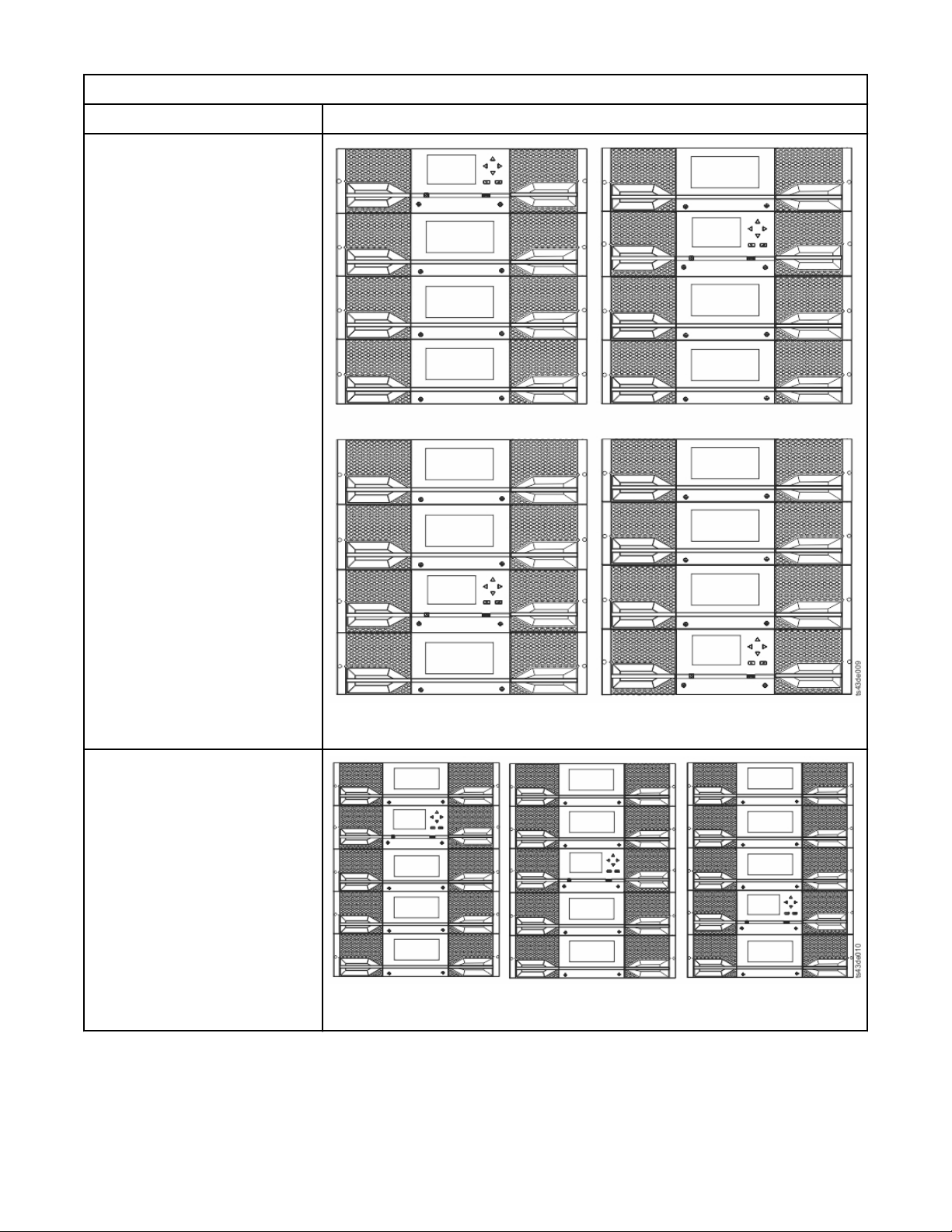
Table 4. Library congurations (continued)
Module quantity Supported library conguration
4 module library
Base Module, and
3 Expansion Modules
5 module library
Base Module, and
4 Expansion Modules
Figure 7. 4 module library
Figure 8. 5 module library
4 Dell EMC ML3 Tape Library: User's Guide
Page 37
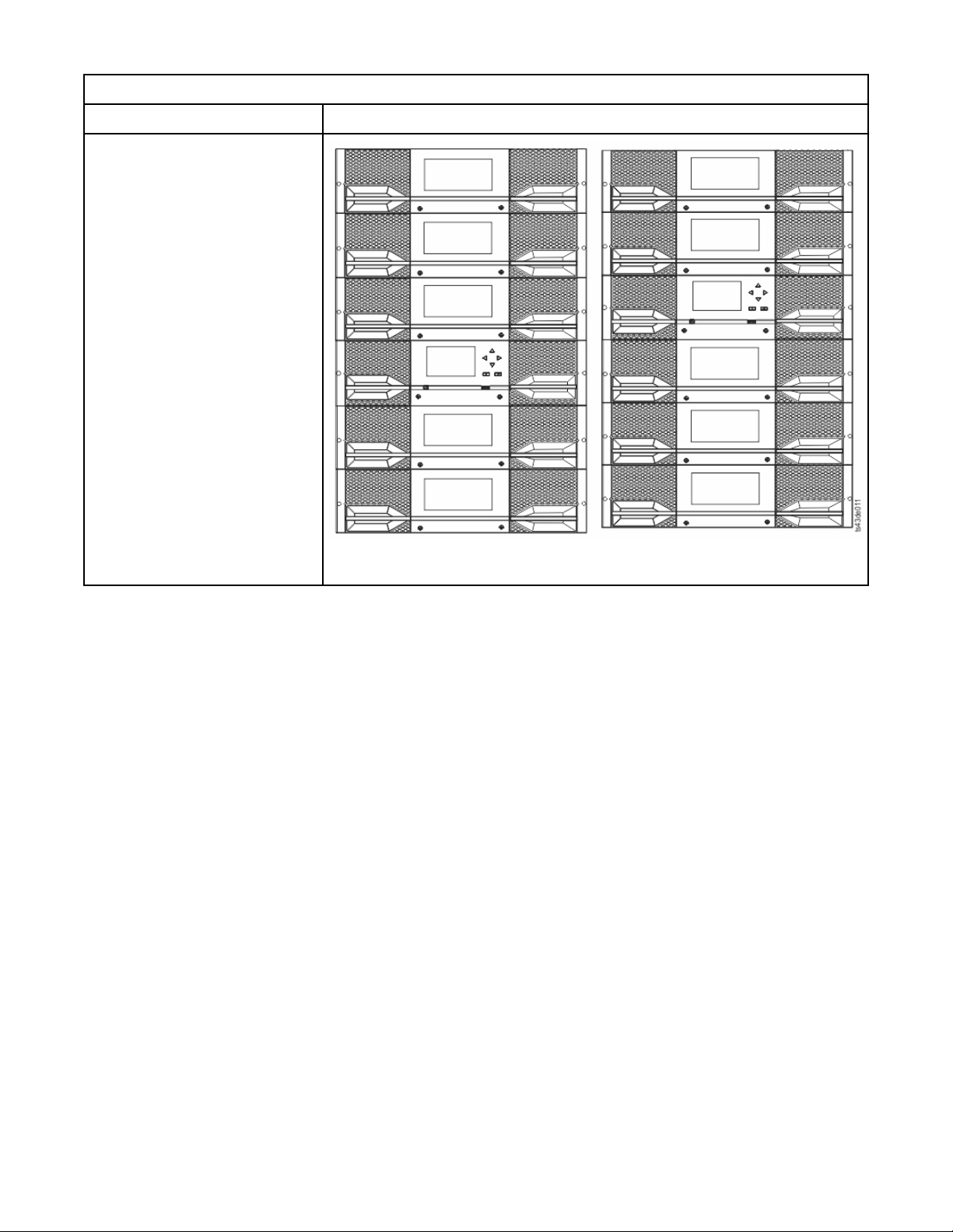
Table 4. Library congurations (continued)
Module quantity Supported library conguration
6 module library
Base Module, and
5 Expansion Modules
Figure 9. 6 Module library
Chapter 1. Overview 5
Page 38
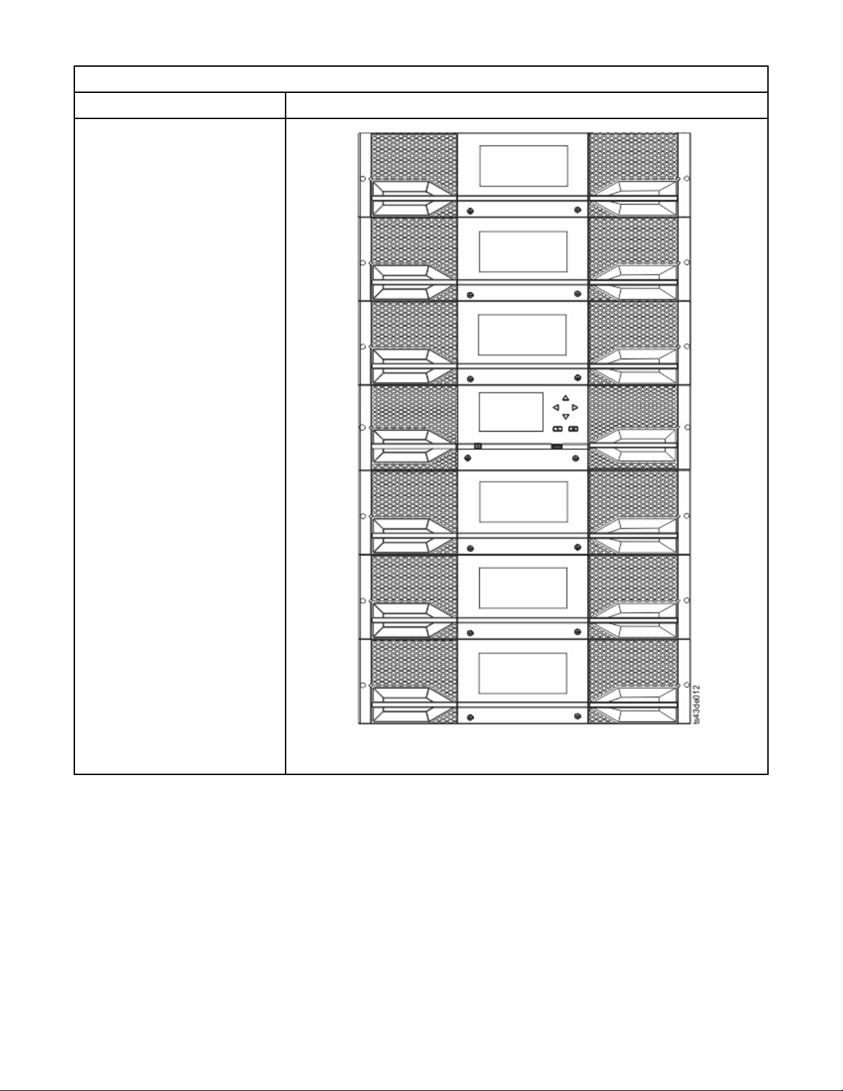
Table 4. Library congurations (continued)
Module quantity Supported library conguration
7 module library
Base Module, and
6 Expansion Modules
Figure 10. 7 module library
Components
6
Dell EMC ML3 Tape Library: User's Guide
Page 39

Front panel
Figure 11. Front panel
Table 5. Front panel descriptions
Number Item Comments
1 Screw holes for attachment to a rack
2 Left magazine access handle
3 Power Base Module only
4 Ready LED, Green Base Module only
5 Unit Identication LED, Blue Base Module only
6 Clean LED, Amber Base Module only
7 Attention LED, Amber Base Module only
8 Error LED, Amber Base Module only
9 USB port Base Module only
10 Operator Panel display Base Module only
11 Back/Return button Base Module only
12 Navigation button - Left Base Module only
13 Navigation button - Up Base Module only
14 Navigation button - Down Base Module only
15 Navigation button - Right Base Module only
16 Enter button Base Module only
18 I/O station/Right magazine access handle
19 Right magazine button
20 Left magazine button
21 Manual magazine release hole
Chapter 1. Overview 7
Page 40

Rear panel
Figure 12. Rear panel
Table 6. Rear panel descriptions
Number Item Comments
1 Power supply 1
2 Power supply 2 Optional on Base Module and Expansion Modules
3 Tape drive bays
4 Upper Expansion Module connection port
5 USB port Base Module only
6 Ethernet port B Base Module only (secondary port for service
7 Ethernet port A Base Module only
8 Module alignment mechanism
9 Lower Expansion Module connection port
10 Unit Identier LED, Blue
11 Controller Error LED, Yellow
13 Product Serial Number, Tag location
Physical and logical addresses of modules
Standard on Base Module
Optional on Expansion Module (required
if drives are present)
usage)
The library assigns each module a unique address to indicate its physical location, shown in Figure 13 on
page 9. The physical numbering is bottom up on all modules.
8
Dell EMC ML3 Tape Library: User's Guide
Page 41

Figure 13. Physical numbering of modules
Magazines
Each module contains two magazines, holding up to 40 cartridges.
Figure 14. Left magazine
Chapter 1. Overview
9
Page 42
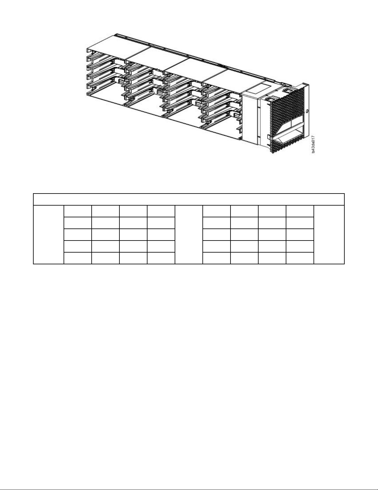
Figure 15. Right magazine
The library assigns each slot in a magazine a unique number to indicate its physical location. This
numbering is shown on the Cartridges page of the Management GUI.
Table 7. Physical numbering of storage slots - bottom module
5 10 15 20
Front of
the Left
Magazin
e
4 9 14 19 24 29 34 39
3 8 13 18 23 28 33 38
2 7 12 17 22 27 32 37
1 6 11 16 21 26 31 36
Physical numbering of storage slots starts with the left magazine of the lowest module of your library. As
modules are added above this module, the numbering continues, starting with the lower left slot of the
left magazine, and adding 40 storage slots for each additional module.
Note: For libraries with serial numbers before 7800K0K, the slots in the lowest row (1, 6, 11, 16, 21, 26,
31, 36) of the bottom module are inaccessible, and can contain a 4-slot I/O station only.
Each module can be congured to contain an I/O Station, or one I/O Station can be accessed by several
modules. I/O Stations consist of ve slots in the front column of the right magazine of each module,
except for the lowest module. To enable or disable I/O Stations, go to Library > Modules and Magazines
> Actions > Enable or Disable I/O Station in the Management GUI.
Important: Ensure that no tapes are in the slots before the I/O Station is enabled or disabled.
Accessor
The accessor is composed of several components: robotic assembly, spooling mechanism, and bar code
reader.
Drives
25 30 35 40
Front of
the
Right
Magazin
e
• The robotic assembly has ngers that enable it to grab tape cartridges and move them to and from the
I/O station, storage slots, and drives.
• The spooling mechanism has a cable that extracts and retracts based on movement of the robotic
assembly. This cable provides communication between the robotic assembly and the library main
board.
• The high-speed bar code reader is a part of the Base Module. The bar code reader provides inventory
feedback to the host application, Operator Panel display, and Management GUI by reading cartridge bar
code labels. The library stores the customized inventory data in memory. Library rmware supports a 6
10
Dell EMC ML3 Tape Library: User's Guide
Page 43

or 8 character volume serial number (VOLSER) on the bar code label on the tape cartridge. It is highly
recommended to use bar code labeled cartridges. See “Labeling tape cartridges” on page 160.
Note: For libraries with S/N 7800K0K and higher, review the “Minimum rmware levels for common
library features” on page iii.
Power supply
The library provides a single power supply with each library. However, a secondary redundant power
supply for the base module can be added. In addition, each expansion module with drives installed
requires a power supply.
Figure 16. Power supply rear panel LEDs
Table 8. Power supply LEDs
Number Color Description
1 Green Module powered ON.
2 White AC power is connected.
User interfaces
This library has two user interfaces: the Management GUI and the Operator Panel.
• “The Management GUI” on page 59 - With the Management GUI, you can monitor, congure, and
control the library from a web browser. The Management GUI hosts a dedicated, protected Internet site
that displays a graphical representation of the library. For information on network connectivity, see
“Network connectivity” on page 21.
• “The Operator Panel” on page 62 - With the Operator Panel, you can monitor, congure, and control
the library from the front panel. Functions are limited to those applicable to being in front of the library.
Supported tape drives
The library supports LTO6 and later tape drives. Each drive requires a SAS or Fibre Channel cable.
For minimum and maximum storage congurations, see Table 3 on page 2. For minimum rmware levels,
see “Minimum rmware levels for common library features” on page iii.
Listed are the tape drives that are implemented and qualied for use in this library.
Chapter 1. Overview
11
Page 44

Table 9. Supported tape drives
Type Form factor
(height)
LTO6 1U (Half-
height)
LTO6 1U (Half-
height)
LTO6 2U (Full-height) Fibre Channel
LTO7 1U (Half-
height)
LTO7 1U (Half-
height)
LTO7 2U (Full-height) Fibre Channel
LTO8 1U (Half-
height)
LTO8 1U (Half-
height)
LTO8 2U (Full-height) Fibre Channel
Interface Number of
Serial Attached
SCSI (SAS)
Fibre Channel
(FC)
(FC)
Serial Attached
SCSI (SAS)
Fibre Channel
(FC)
(FC)
Serial Attached
SCSI (SAS)
Fibre Channel
(FC)
(FC)
Speeds of
Ports
2 6 Gbps SAS 160 MB/s
1 8 Gbps FC 160 MB/s
2 8 Gbps FC 160 MB/s
2 6 Gbps SAS 300 MB/s
1 8 Gbps FC 300 MB/s
2 8 Gbps FC 300 MB/s
2 6 Gbps SAS 300 MB/s
1 8 Gbps FC 300 MB/s
2 8 Gbps FC 360 MB/s
connectivity
Native data
rate
The LTO tape drives communicate with the library through an internal Ethernet interface. For enhanced
performance, the LTO tape drives include speed matching, channel calibration, and power management.
Speed matching dynamically adjusts the drive’s normal native (uncompressed) data rate to the slower
data rate of a server. Channel calibration customizes each read/write data channel for optimum
performance. The customization enables compensation for variations in the recording channel transfer
function, media characteristics, and read/write head characteristics. Power® management reduces the
drive’s power consumption during idle power periods.
Control path drives
A control path is a logical path to the library.
A control path is the path for SCSI Medium Changer commands that are sent by a server to control a
specic logical library. The library has no direct SCSI connection to a host server. When a software host
server communicates with the library, it sends the communication by way of a tape drive. The tape drive
is designated as a control path drive.
Mixed drives
All supported generations of LTO tape drives and cartridges can be in the same physical library and within
a single module.
This library supports a mixture of LTO drive types in a logical library. Some independent software vendors
(ISVs) support mixed drive types within a logical library and other do not. Some ISVs that support mixed
drive types might have restrictions. For details, contact your ISV.
Figure 17 on page 13
shows examples of methods for mixing LTO drive types in a logical library.
12
Dell EMC ML3 Tape Library: User's Guide
Page 45
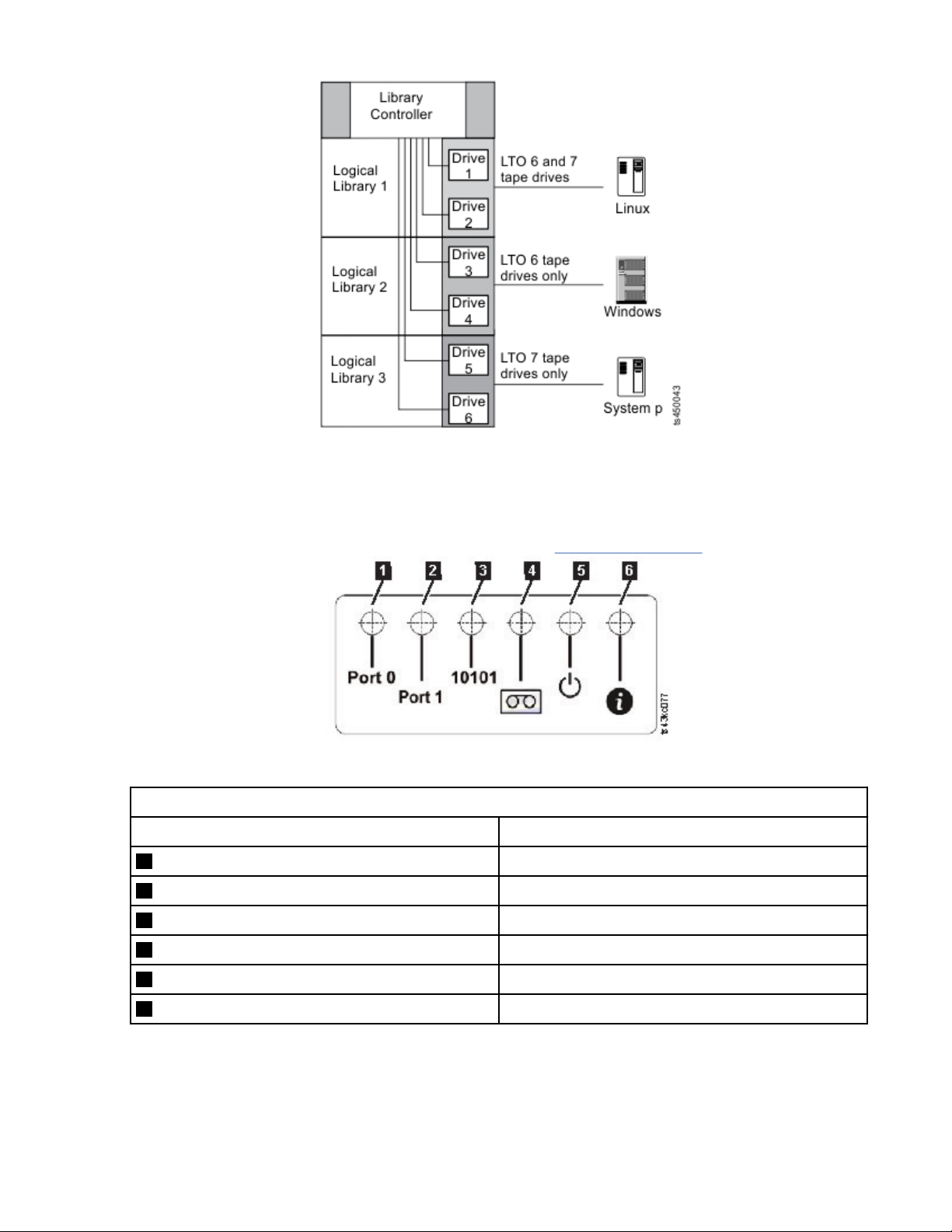
Figure 17. Mixed drives in a logical library
Drive sled back panels
Indicator LEDs are included on all drive sled back panels.
Six indicator LEDs are included on all drive sleds as shown in Figure 18 on page 13
Figure 18. Drive sled indicators
Table 10. Drive sled indicators
Number Description
1 Port 0 activity
2 Port 1 activity
3 Library communication
4 Cartridge present
5 Power
.
6 Beacon /UID
Chapter 1. Overview 13
Page 46
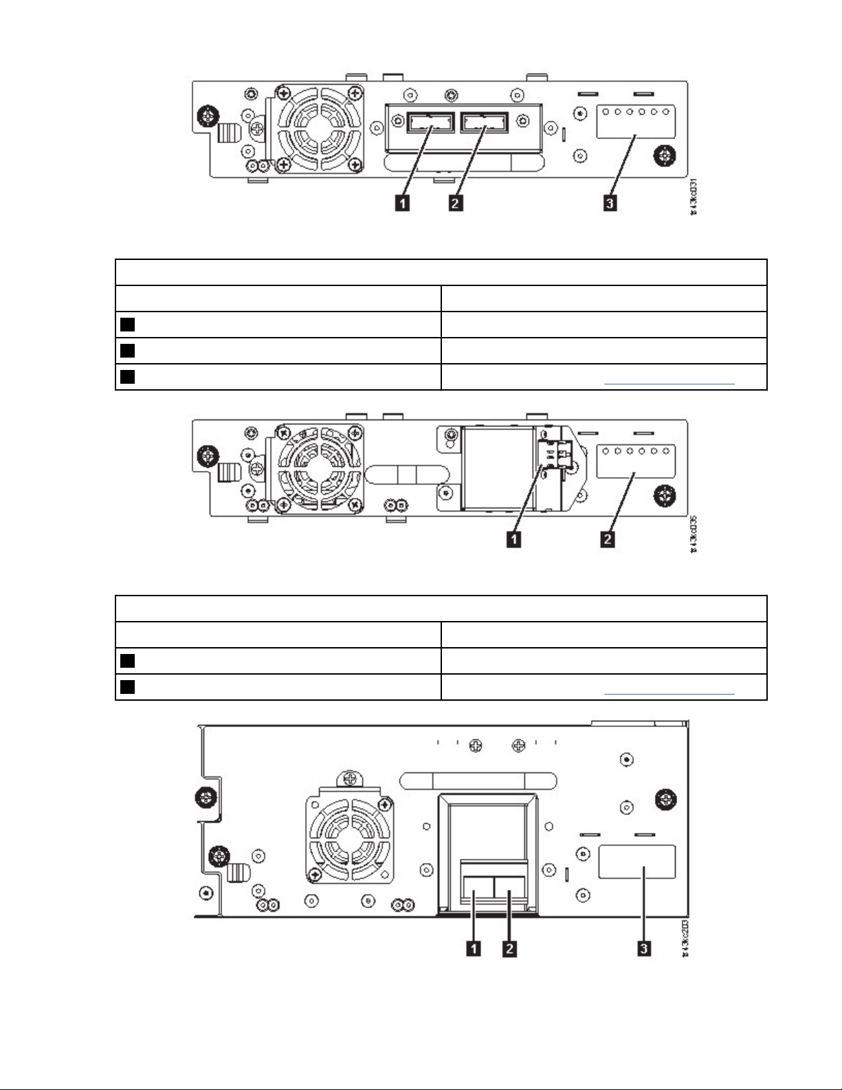
Figure 19. Half-height SAS dual port
Table 11. Half-height SAS dual port
Number Description
1 SAS port 0
2 SAS port 1
3 Drive sled indicators (see Figure 18 on page 13
Figure 20. Half-height FC single port
Table 12. Half-height FC single port
Number Description
1 FC port 0
2 Drive sled indicators (see Figure 18 on page 13
Figure 21. Full-height FC dual port
14
Dell EMC ML3 Tape Library: User's Guide
Page 47
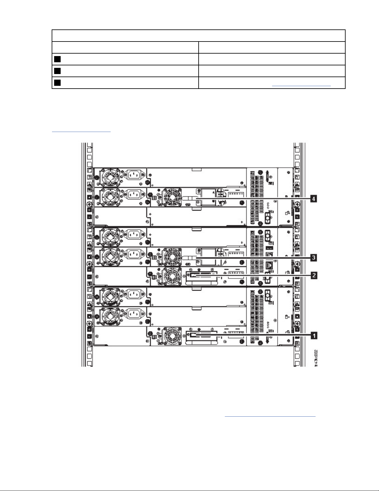
Table 13. Full-height FC dual port
Number Description
1 FC port 0
2 FC port 1
3 Drive sled indicators (see Figure 18 on page 13
Physical and logical addresses of drives
The library assigns each tape drive a unique address to indicate its physical and logical location.
The library assigns each tape drive a unique address to indicate its physical location, which is shown in
Figure 22 on page 15. The physical numbering is bottom up on all drives. This information is shown on
the Drives page of the Management GUI.
Figure 22. Physical numbering of drives
The library assigns each tape drive a SCSI element address that consists of a value that denes a logical
location in the library to the SCSI interface. It is assigned and used by the application when the host
server processes SCSI commands. The SCSI element address for a drive is unique to the location of the
drive. It does not vary based on other drives in the library. See “Library partitioning” on page 57.
Chapter 1. Overview
15
Page 48

Supported tape cartridges
This library supports LTO tape cartridges.
Within the library, the supported LTO tape drives use the following cartridge types:
• LTO8 Data Cartridge
• LTO8 WORM Data Cartridge
• LTO M8 Data Cartridge
• LTO7 Data Cartridge
• LTO7 WORM Data Cartridge
• LTO6 Data Cartridge
• LTO6 WORM Data Cartridge
• LTO5 Data Cartridge
• LTO5 WORM Data Cartridge
• LTO4 Data Cartridge
• LTO4 WORM Data Cartridge
• Universal LTO Cleaning Cartridge
For information, see Appendix C, “LTO media,” on page 157.
Library functions
The library provides many specic functions, such as random or sequential operating mode, encryption,
library sharing, path failover, and alerts and logging.
Random and Sequential Logical Library modes
A Logical Library can be congured in one of two modes: Random and Sequential.
Random Mode
Random Mode is intended to be used by host applications that support SCSI media changer devices.
Random Mode is the default.
In Random mode,
• The host application chooses the cartridges that are moved to the drive.
• I/O slots provide the flexibility for the user to add and remove cartridges and the host application is
automatically notied of these changes.
• Multiple drives can be assigned to provide parallel processing data operations and redundancy in case
of failure.
Sequential Mode
Sequential Mode is intended to be used by host applications that aren’t supporting SCSI media changer
devices but need to get another cartridge loaded if the current cartridge is full.
In Sequential Mode,
• The library predenes the sequential order that the cartridges are moved to the drive.
• I/O slots are hidden as they aren’t assignable to a logical library with sequential mode enabled.
• Only one drive can be assigned to a logical library with sequential mode enabled.
• There’s no control path drive and no media changer device is congured to the host server.
Options to consider when Sequential Mode is chosen:
16
Dell EMC ML3 Tape Library: User's Guide
Page 49

• Basic Function - To initiate use of cartridges, the user issues a Move Cartridge command to the drive
through the Management GUI. After the load, the host application can begin data I/O activity. When the
host application unloads the drive, the library moves the next cartridge into the drive. This behavior is
implicit, unless otherwise dened by selection of another option.
• Loop Option - If a move sequence ends because no more cartridges are available in the current logical
library, the sequence starts again by loading the rst cartridge of the logical library. This option can be
chosen with or without the Autoload function.
• Autoload Option - If enabled, the library loads the rst cartridge of the logical library to the Sequential
Mode tape drive during library startup after inventory scan is nished. This option changes the implicit
behavior of the Basic function. This option can be chosen with or without the Loop option.
If storage slots are congured to I/O slots after assignment to a Sequential Mode logical library, they are
still considered valid available slots and are used for movements. This option stays until you run the
expert wizard again, and then these I/O slots no longer appear in the list of available slots. Finishing the
expert wizard then sets the new slot assignment and these I/O slots can no longer be used for
movements.
To enable sequential mode, click the Enable Sequential Mode check box in the Basic Logical Library
Wizard or Expert Logical Library Wizard.
Encryption
All supported tape drives in this library support encryption.
The encryption enabled drive contains the necessary hardware and rmware to encrypt and decrypt host
tape application data. Encryption policy and encryption keys are provided by the host application or host
server. A drive digital certicate is installed at manufacturing time. Each drive receives a unique serial
number and certicate. The T10 application might validate each drive instance by checking the drive's
digital certicate.
The library provides these options.
1. Encryption disabled
2. Application Managed Encryption (AME)
3. Library Managed Encryption (LME). LME is a built-in feature. For conguration details, see
“Conguring Library Managed Encryption” on page 72
The default is Application Managed Encryption.
Enabling library-managed encryption on a Dell EMC ML3 is a six-step process.
1. Upgrade the library and drive rmware to the current versions. The rmware can be found at
www.Dell.com/support.
2. Library-managed encryption on the library is already activated and cannot be deactivated.
If issues occur with the library-managed encryption on the library, go to http://www.dell.com/
tapeautomation for information on resolving the issue. If your issue is not resolved, contact Dell
technical support.
3. Congure library-managed encryption on your library.
4. Install the IBM SKLM application on the server that is designated as the key manager. See IBM SKLM
Knowledge Center for information.
5. Congure the IBM SKLM application. See IBM SKLM Knowledge Center for information.
6. Start the IBM SKLM application. See IBM SKLM Knowledge Center for information.
Note: All encryption settings must be congured or reveried in the drive after any library or drive reset. A
new drive might be added or an existing drive might be swapped with another drive.
.
Chapter 1. Overview
17
Page 50

Library sharing
The library can be congured into one or more logical libraries that can be shared by multiple
applications.
It is advantageous to be able to share a single physical library between heterogeneous or homogeneous
applications. However, some applications (and some servers) do not allow for sharing a library between
systems.
The library Management GUI provides two methods for logical library conguration.
1. A quick conguration for a simple one logical library conguration
2. An advanced conguration action for a multiple logical library conguration
Note: When any number of drives are loaded, a warning message appears when the Manage Logical
Library (Expert Mode) wizard is accessed.
The second method gives the ability to create congurations that enable the library to process commands
from multiple heterogeneous applications (such as a Windows application) and multiple homogeneous
applications (for example, the same application run by several System p servers). See “Advanced library
conguration” on page 56.
Control path failover, Data path failover, and load balancing
The path failover feature ensures the use of a redundant communication path when the primary path fails.
Command failures and time outs are costly. You want your library to run smoothly and efciently. Path
failover capabilities allow the device driver to resend a command to an alternate path. The alternate path
can include another host bus adapter (HBA), Storage Area Network (SAN), or library control path drive.
The device driver initiates error recovery and continues the operation on the alternate path without
interrupting the application.
Path failover and load balancing are built-in features that are enabled by using a purchased license. The
path failover feature can be ordered from the factory, or you can order it as a eld upgrade. The path
failover feature is activated on the Management GUI. To order features, contact your Sales
Representative or Business Partner.
Two types of path failover capabilities exist: control path failover (CPF) and data path failover (DPF).
Control refers to the command set that controls the library (the SCSI Medium Changer command set
on LUN 1 of the tape drives). Data refers to the command set that carries the customer data to and from
the tape drives (the SCSI-3 Stream Commands (SSC) device on LUN 0 of the tape drives). Path failover
means the same thing in both. Path failover is where redundancy is in the path from the application to the
intended target (the library accessor or the drive mechanism), the device driver transparently fails over to
another path in response to a break in the active path.
Both types of failover include host-side failover when congured with multiple HBA ports into a switch.
But CPF includes target-side failover through the control paths that are enabled on more than one tape
drive. DPF includes target-side failover for the dual-ported tape drives that are supported by the library.
DPF includes load balancing of the HBAs because the channel is a data-intensive path (the control path
carries little data, so load balancing is not an issue). The dynamic load balancing support optimizes
resources for devices that have physical connections to multiple HBAs in the same machine. When an
application opens a device where multiple HBA paths are congured, the device driver determines which
path has the HBA with the lowest usage and assigns that path to the application. When another
application opens a different device with multiple HBA paths, the device driver again determines the path
with the lowest HBA usage and assigns that path to the second application. The device driver updates the
usage on the HBA assigned to the application when the device is closed. Dynamic load balancing uses all
HBAs whenever possible and balances the load between them to optimize the resources in the machine.
Both CPF and DPF require the use of the current device driver. They are supported exclusively with
products that bear the Dell logo on the operating systems that is indicated in Table 14 on page 19
Table 14 on page 19 summarizes the differences between CPF, DPF, and load balancing.
18
Dell EMC ML3 Tape Library: User's Guide
.
Page 51

Table 14. Differences between CPF and DPF
Characteristic CPF DPF and Load Balancing
Device type SMC
3
LUN
1
LUN 1 LUN 0
Host-side failover Yes Yes
Target-side failover Yes Yes
SSC
2
6
6
Device driver required Yes Yes
Supported operating systems
4
AIX®, SuSE Linux, Red Hat
Enterprise Linux, Solaris,
Windows
AIX, SuSE Linux, Red Hat
Enterprise Linux, Solaris,
Windows5 (DPF only)
Order feature to obtain license Yes Yes
Notes:
1. SMC = SCSI-3 Medium Changer Specication (library)
2. SSC = SCSI-3 Stream Commands (drive)
3. LUN = logical unit number
4. See “Host connectivity” on page 20 for details.
5. Load balancing is not supported on Windows
6. Full-height tape drives only
Alerts and logging
The library sends alerts about the library and attached tape drives, and offers audit-logging to track user
actions.
• TapeAlert Support: The tape library is compatible with TapeAlert technology, which provides error and
diagnostic information about the drives and the library to the host application. The library provides this
error and diagnostic information as TapeAlert flags that are reported to the application by the SCSI
LOG SENSE command. See “TapeAlert flags” on page 105.
• Email (SMTP - Simple Mail Transfer Protocol) Notications: The library can congure email
notication of library events. The library must have network access to an SMTP server. See “Locating
Management functions” on page 63.
• Remote Logging (rsyslog): The library can send syslog (system log) notications to a congured remote
(rsyslog) server. When system events occur, the ML3 tape library creates a log of these events. With this
notication feature congured, the library sends a notication of the event to the syslog server. The
syslog server keeps its own log of system events. (The syslog server is a customer-provided server.) See
“Locating Management functions” on page 63.
• SNMP Support: The Simple Network Management Protocol (SNMP) allows the library to send alerts
over a LAN network to a monitoring server.
Occasionally, the library might encounter situations that you want to know about. These situations can
be conditions that affect the library performance, such as an open door that causes the library to stop.
You might also want to log user actions, such as a cartridge move or export that is initiated from the
Management GUI. SNMP messages can alert you of these conditions.
The library provides a standard TCP/IP protocol that is called SNMP to send alerts about conditions over
a TCP/IP LAN network to an SNMP monitoring server. These alerts are called SNMP traps. Using the
information that is supplied in each SNMP trap, the monitoring server (together with customer-supplied
software) can alert operations staff of possible problems or operator interventions that occur. Many
monitoring servers can be used to send email or pager notications when they receive an SNMP alert.
See the manual for your network management application.
Chapter 1. Overview
19
Page 52

The monitoring server must be loaded with systems management software that can receive and
process the trap. SNMP supports a get and get-response mechanism for an operator to gather more
information about a problem or query the library about its status. Through a monitoring server, the
operator enters a "get" using SNMP to request information about the library. A get-response is the
information that is provided in response to the get. This type of support generally requires an up-todate library Management Information Base (MIB). The SNMP server's MIB contains units of information
that specically describe an aspect of a system, such as the system name, hardware number, or
communications conguration.
SNMP Notication Levels
SNMP provides various levels of notication about specic library events and user actions.
– Inactive – No events are sent.
– Critical – Only critical events are sent.
– + Warnings – Only critical and warning events are sent.
– + Conguration – Only critical, warning, and conguration events are sent.
– + Information – All events are sent.
Simple Network Management Protocol (SNMP) audit logging provides logging information about specic
tape library user actions. To congure SNMP, see “Locating Management functions” on page 63.
Host connectivity
The library is supported by a wide variety of servers, operating systems, and adapters. There are many
ways to determine the servers and software that support this library.
Compatible servers and software
These attachments can change throughout the lifecycle of the product. To determine the newest
attachments, or to get a comprehensive list of compatible software, do one of the following actions.
• For a list of compatible software, operating systems, and servers for LTO tape drives, see
www.Dell.com/support.
Notes:
1. Dell does not provide application software with this library. To order software, contact your sales
representative, Business Partner, or an independent software provider.
2. If you attach your library to a server with non-Dell software, contact your software vendor for a
matrix of compatible hardware, software, rmware revisions, and adapter cards.
Note: Dependent on the use of Random or Sequential Mode, the library might require an HBA with
multiple LUN supports. Also, multiple LUN supports must be enabled on the host computer. When
multiple LUN supports are not enabled, the host computer can see the tape drive, but not the library. See
“Random and Sequential Logical Library modes” on page 16.
Supported device drivers
Dell provides device driver support for the LTO tape drives, and the robotics in this library.
Dell maintains the current levels of device drivers and driver documentation on the web. Go to
www.Dell.com/support and follow the steps to access this material.
20
Dell EMC ML3 Tape Library: User's Guide
Page 53

Network connectivity
This library supports various browsers and interfaces.
Supported browsers
Dell supports higher versions of the browsers if the vendors don’t remove or disable functions that the
product relies upon. For browser levels higher than the versions that are certied with the product,
customer support accepts usage-related and defect-related service requests. As with operating system
and virtualization environments, if Dell support can’t re-create the issue in the lab, the client might be
asked to re-create the problem on a certied browser version to determine whether a product defect
exists. Defects aren’t accepted for cosmetic differences between browsers or browser versions that don’t
affect the functional behavior of the product. If a problem is identied in the product, defects are
accepted. If a problem is identied with the browser, Dell might investigate potential solutions or
workarounds that the client can implement until a permanent solution becomes available.
Supported interfaces
This tape library supports the Gigabit Ethernet interface in either auto negotiation or xed modes of 10
Mbps, 100 Mbps, and 1 Gbps by using half or full duplex. The library supports the following TCP/IP
protocols:
IPv4 and IPv6 support
This tape library supports Internet Protocol (IP) addresses in both IPv4 and IPv6 format. Both the
integrated management console (IMC) and the management GUI allow the denition of IPv4 and IPv6
addresses. The key proxy determines the IP version that is used and presents the correct IP address
and parameters to the IP Stack.
Simple Network Management Protocol (SNMP)
SNMP traps are supported for drive and library events. SNMP management query functions are
supported by using a standard Management Information Block (MIB).
Hyper Text Transfer Protocol (HTTP)
An embedded web server provides a management GUI for library management and query capabilities.
Secure Socket Layer (SSL)
The tape library supports SSL, a protocol for transmitting private documents through the internet.
Key Management Interoperability Protocol (KMIP)
Used for communicating with the IBM® Security Lifecycle Key Manager and other security key
management software.
Simple Mail Transfer Protocol (SMTP)
The tape library supports SMTP for sending email alerts.
Network Time Protocol (NTP)
The tape library supports NTP for external time-and-date synchronization.
Lightweight Directory Access Protocol (LDAP)
The tape library supports LDAP for centralized authentication.
Domain Name System (DNS)
The tape library supports DNS for flexible IP addressing.
Dynamic Host Conguration Protocol (DHCP)
The library supports DHCP for automatically providing an Internet Protocol (IP) host with its IP
address and other related conguration information, such as the subnet mask and default gateway.
Chapter 1. Overview
21
Page 54

Chapter 2. Planning
The library requires an environment able to accommodate the appropriate space, power, location, and
other technical specications. Use this section as a reference for onsite requirements to allow for
optimum operation of the library.
Save your settings in the Appendix A, “Library Conguration Forms,” on page 146.
Library Layout and Location requirements
Information for planning the installation and layout of your library, including various specications for
optimal performance.
For tabletop installation - Tabletop installations (one Base Module) require no additional hardware.
For rackmount installation - If possible, install the Base Module in the middle of the rack to provide space
for the allowed three Expansion Modules above it and three Expansion Modules below it. See “Structure
and supported library congurations” on page 2 for details.
Security
The equipment must be located so that access to the equipment can be controlled and monitored.
Consider all of these recommended security measures when you’re determining where to locate your
tape library.
Library location
You’re responsible for the security of this library, the cartridges that are contained within the library,
and shelf-resident cartridges. To prevent unauthorized access to data, Dell recommends locating the
library and all shelf-resident cartridges in an area where access is controlled.
Onsite security measures
You’re also responsible for evaluating, selecting, and implementing security features, administrative
procedures, and appropriate controls in application systems and communication facilities.
Data security
Data security is accomplished through the Management GUI. See “Locating Management functions”
on page 63.
Location requirements
Choose a location that meets the criteria in Table 15 on page 22.
Table 15. Location requirements
Criteria Denition
Rack requirements Standard 19-inch rack (minimum depth of 1 meter) with an appropriate # of
Us (Rack Units) of clearance for the planned module quantity (See Table 16
on page 23 for details.)
Rack space requirements 3U for the Base Module and 3U for each Expansion Module
Power source
22 Dell EMC ML3 Tape Library: User's Guide
• AC Power Voltage: 100 - 240 VAC
• Line Frequency: 50 - 60 Hz
• Library is located near AC outlet.
The AC power cord must be always easily accessible.
Page 55

Table 15. Location requirements (continued)
Criteria Denition
Air quality
• Place the library in an area with minimal sources of particulate
contamination.
• Avoid areas near frequently used doors and walkways, stacks of supplies
that collect dust, printers, and smoke-lled rooms.
• Excessive dust and debris can damage tapes and tape drive.
Technical specications for this library can be referenced in the following tables.
Physical specications
Table 16. Physical specications
Characteristic Product alone Packaged
Height 133 mm 330 mm
Width 480 mm
Depth 885 mm
Weight
Base module: 20 Kg
Expansion module: 14 Kg
1
Includes front covering of rack rails, allowing for magazine opening clearance.
2
Includes front covering and drive fan.
1
2
640 mm
1160 mm
Base module: 25 Kg
Expansion module: 19 Kg
Electrical specications for one module (base or expansion)
Table 17. Electrical
specications for one module (base or expansion)
Characteristic Specication
Current max. 12.5 A
Voltage 100 - 240 V 50/60 Hz
Power 300 W
Chapter 2. Planning 23
Page 56

Equipment environmental specications
Table 18. Equipment environment specications for the tape library
Product operation (equipment is powered on) Product power off
Dry-bulb temperature Humidity range, non-condensing
Allowable
16°C to 32°C
(60°F to
90°F)
Notes:
1. Product equipment is removed from the original shipping container and installed but not in use - for example, during repair, maintenance, or upgrade.
2. Derate maximum dry-bulb temperature 1°C/300 m above 900 m (1.8°F/1,000 feet above 3,000 feet).
3. Derate maximum recommended dry-bulb temperature 1°C/300 m above 1,800 m (1.8°F/1,000 feet above 6,000 feet).
d
16°C to 25°C
(60°F to
77°F)
Recommende
2
3
Maximum rate
of change
5°C/hour
(9°F/hour)
Allowable
20 to 80% RH 20 to 50% RH
RecommendedMaximum rate
of change
5% RH/hour
with no
condensation
Maximum
wet-bulb
temperature
26°C (79°F)
Maximum
elevation
3050 m
(10,000 feet)
Dry-bulb
temperature
5°C to 45°C
(40°F to
113°F)
1
Relative
humidity
8 to 80% RH 26°C (79°F)
Maximum
wet-bulb
temperature
24 Dell EMC ML3 Tape Library: User's Guide
Page 57

Psychrometric chart
Figure 23. Psychrometric chart showing recommended and allowable operating environments for the tape
library
Notes:
• The chart is shown in SI (metric) units and a barometric pressure of 101.325 kPa (sea level).
• The recommended operating environment species a long-term operating environment that can result
in the greatest reliability and energy efciency.
• The allowable operating environment represents where the equipment was tested to verify functions.
Due to the stresses that operating in the allowable envelope can place on the equipment, these
envelopes should be used for short-term operation, not continuous operation (for example, in the case
of a cooling failure).
Chapter 2. Planning
25
Page 58

Gas and particulate exposure
Table 19. Gas and particulate exposure
Contamination Requirement
Gaseous contamination Severity level G1 as per ANSI/ISA 71.04-19851, which states that the reactivity rate
of copper coupons shall be fewer than 300 Angstroms per month (Å/month, ≈
0.0039 µg/cm² - hour weight gain)2. In addition, the reactivity rate of silver coupons
shall be less than 300 Å/month (≈ 0.0035 µg/cm² - hour weight gain)3. The reactive
monitoring of gaseous corrosivity should be conducted approximately 5 cm (2 in.) in
front of the rack on the air inlet side at one-quarter and three-quarter frame height
off the floor or where the air velocity is much higher.
Particulate
contamination
Notes:
1. ANSI/ISA-S71.04. 1985. Environmental conditions for process measurement and control systems: Airborne
contaminants, Instrument Society of America, Research Triangle Park, NC, 1985.
2. The derivation of the equivalence between the rate of copper corrosion product thickness growth in Å/
month and the rate of weight gain assumes that Cu2S and Cu2O grow in equal proportions.
3. The derivation of the equivalence between the rate of silver corrosion product thickness growth in Å/month
and the rate of weight gain assumes that Ag2S is the only corrosion product.
4. The deliquescent relative humidity of particulate contamination is the relative humidity at which the dust
absorbs enough water to become wet and promote ionic conduction.
5. Surface debris is randomly collected from 10 areas of the data center on a 1.5-cm diameter disk of sticky
electrically conductive tape on a metal stub. If examination of the sticky tape in a scanning electron
microscope reveals no zinc whiskers, the data center is considered free of zinc whiskers.
Data centers must meet the cleanliness level of ISO 14644-1 class 8. For data
centers without airside economizer, the ISO 14644-1 class 8 cleanliness might be
met by the choice of the following ltration:
• The room air might be continuously ltered with MERV 8 lters.
• Air entering a data center might be ltered with MERV 11 or preferably MERV 13
lters.
For data centers with airside economizers, the choice of lters to achieve ISO class 8
cleanliness depends on the specic conditions present at that data center. The
deliquescent relative humidity of the particulate contamination should be more than
60% RH.34.Data centers must be free of zinc whiskers5.
26 Dell EMC ML3 Tape Library: User's Guide
Page 59

Power cords
Electrical and safety information, and feature codes for purchasing power cords.
Table 20. Power cords
To avoid electrical shock, a power cord with a grounded attachment plug is provided.
Use only properly grounded outlets.
Table 20 on page 27 lists the power cord part number, feature code, the country, or
region where the power cord is used, and the plug's standard reference. The last column
in the table contains an index number that you can match to a specic receptacle type in
Figure 24 on page 31.
All power cords use an appliance coupler that complies with the International
Electrotechnical Commission (IEC) Standard 320, Sheet C13.
If the power cord that you receive does not match your receptacle, contact your local
dealer.
Power cords that are used in the United States and Canada are listed by Underwriter's
Laboratories (UL), are certied by the Canadian Standards Association (CSA), and
comply with the plug standards of the National Electrical Manufacturers Association
(NEMA). For other worldwide geographies, plug standards are listed in Table 20 on page
27.
Description, Feature
Code (FC), and Part
Number (P/N)
US/Canada
• 2.8 m, 125 V
• FC 9800
• P/N 95P2344
Chicago
• 1.8 m, 125 V
• FC 9986
• P/N 39M5080
Plug Standard
Reference
NEMA 5-15P Aruba, Bahamas, Barbados,
NEMA 5-15P Chicago, U.S.A. 1
Country or Region Index Number in Figure 24
on page 31
Bermuda, Bolivia, Brazil,
Canada, Cayman Islands,
Colombia, Costa Rica,
Curacao, Dominican
Republic, Ecuador, El
Salvador, Guatemala,
Guyana, Haiti, Honduras,
Jamaica, Japan, Liberia,
Mexico, Netherlands
Antilles, Nicaragua,
Panama, Peru, Philippines,
Saudi Arabia, South Korea,
Suriname, Taiwan, Trinidad
Tobago, Venezuela, US
1
Chapter 2. Planning 27
Page 60

Table 20. Power cords (continued)
Description, Feature
Code (FC), and Part
Number (P/N)
US/Canada
• 2.8 m, 250 V
• FC 9833
• P/N 95P2353
Australia
• 2.8 m, 250 V
• FC 9831
• P/N 95P2352
France, Germany
• 2.8 m, 250 V
• FC 9820
• P/N 95P2345
Plug Standard
Reference
NEMA 6-15P Aruba, Bahamas, Barbados,
AS 3112
NZS 198
CEE 7 - VII Afghanistan, Algeria,
Country or Region Index Number in Figure 24
Bermuda, Bolivia, Brazil,
Canada, Cayman Islands,
Costa Rica, Curacao,
Dominican Republic,
Ecuador, El Salvador,
Guatemala, Guyana, Haiti,
Honduras, Jamaica, Japan,
Liberia, Netherlands
Antilles, Nicaragua,
Panama, Peru, Philippines,
Suriname, Taiwan, Thailand,
Trinidad Tobago, Venezuela,
US
Australia, China, Colombia,
New Zealand, Papua New
Guinea, Paraguay, Uruguay,
Western Samoa
Andorra, Angola, Aruba,
Austria, Belgium, Benin,
Brazil, Bulgaria, Burkina
Faso, Burundi, Cameroon,
Central African Republic,
Chad, Congo-Brazzaville,
Curacao, Czech Republic,
Democractic Republic of
Congo, Denmark, Egypt,
Finland, France, French
Guiana, Germany, Greece,
Guinea, Hungary, Iceland,
Indonesia, Iran, Ivory Coast,
Jordan, Kenya, Korea,
Lebanon, Luxembourg,
Macau, Malagasy, Mali,
Martinique, Mauritania,
Mauritius, Monaco,
Morocco, Mozambique,
Netherlands, Netherlands
Antilles, New Caledonia,
Niger, Norway, Poland,
Portugal, Romania, Russia,
Saudi Arabia, Senegal,
Spain, Sweden, Sudan,
Syria, Togo, Tunisia, Turkey,
Yugoslavia, Zaire,
Zimbabwe, Vietnam
on page 31
2
3
4
28 Dell EMC ML3 Tape Library: User's Guide
Page 61

Table 20. Power cords (continued)
Description, Feature
Code (FC), and Part
Number (P/N)
Denmark
• 2.8 m, 250 V
• FC 9821
• P/N 95P2346
South Africa
• 2.8 m, 250 V
• FC 9829
• P/N 95P2350
United Kingdom
• 2.8 m, 250 V
• FC 9825
• P/N 95P2347
Plug Standard
Reference
DK2-5A Denmark 5
SABS 164 Bangladesh, Burma,
BS 1363 Antigua, Bahrain, Bermuda,
Country or Region Index Number in Figure 24
Pakistan, South Africa, Sri
Lanka
Brunei, Channel Islands,
China (Hong Kong S.A.R.),
Cyprus, Fiji, Ghana, Guyana,
India, Iraq, Ireland, Jordan,
Kenya, Kuwait, Malaysia,
Malawi, Malta, Nepal,
Nigeria, Oman, Polynesia,
Qatar, Sierra Leone,
Singapore, Tanzania,
Uganda, UK, United Arab
Emirate (Dubai), Yemen,
Zambia
on page 31
6
7
Switzerland
• 2.8 m, 250 V
• FC 9828
• P/N 95P2349
Italy
• 2.8 m, 250 V
• FC 9830
• P/N 95P2351
Israel
• 2.8 m, 250 V
• FC 9827
• P/N 95P2348
Argentina
• 2.8 m, 250 V
• FC 9834
• P/N 95P2354
SEV S/N 416534 Liechtenstein, Switzerland 8
CEI 23- 16 Chile, Ethiopia, Italy, Libya,
Somalia
S11-32-1971 Israel 10
IEC 83-A5 Argentina, Brazil, Colombia,
Paraguay, Trinidad Tobago,
Uruguay
11
9
Chapter 2. Planning 29
Page 62

Table 20. Power cords (continued)
Description, Feature
Code (FC), and Part
Number (P/N)
China
• 2.8 m, 250 V
• FC 9840
• P/N 95P2355
Taiwan LV*
• 2.8 m, 125 V
• FC 9835
• P/N 23R3263
Taiwan HV**
• 2.8 m, 250 V
• FC 9841
• P/N 23R6120
Japan LV*
• 2.8 m, 125 V
• FC 9842
• P/N 23R6121
Plug Standard
Reference
CCEE People's Republic of China 12
CNS 10917-3 Taiwan 13
CNS 10917-3 Taiwan 14
JIS C8303, C8306 Japan 15
Country or Region Index Number in Figure 24
on page 31
Japan HV**
• 2.8 m, 250 V
• FC 9843
• P/N 39M5186
Korea HV**
• 2.8 m, 250 V
• FC 9844
• P/N 23R6123
India HV**
• 2.8 m, 250 V
• FC 9845
• P/N 23R6124
Brazil LV*
• 2.8 m, 125 V
• FC 9846
• P/N 39M5233
JIS C8303, C8306 Japan 16
KS C8305, K60884-1 Korea 17
IS 6538 India 18
InMetro NBR 6147 Brazil 19
30 Dell EMC ML3 Tape Library: User's Guide
Page 63
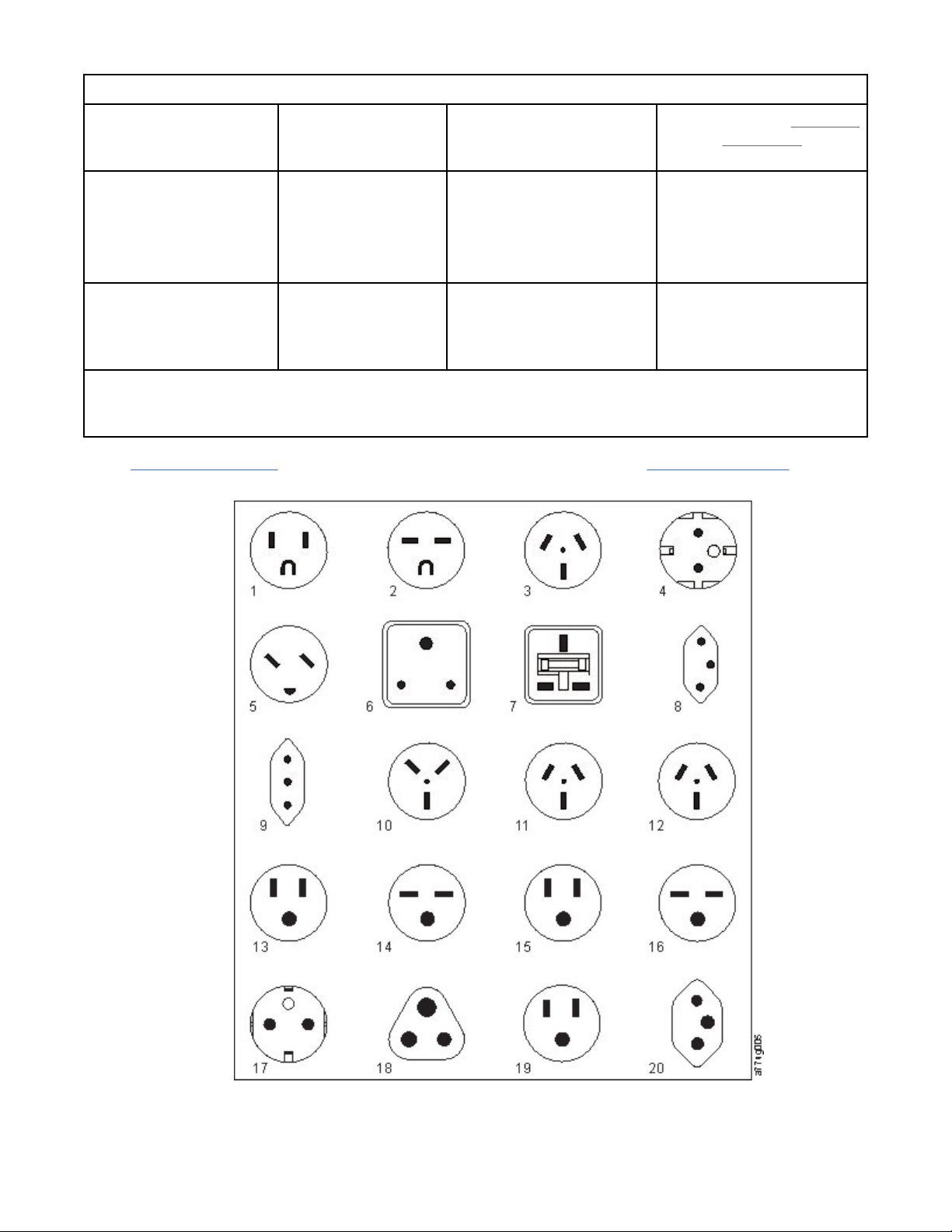
Table 20. Power cords (continued)
Description, Feature
Code (FC), and Part
Number (P/N)
Brazil HV**
• 2.8 m, 250 V
• FC 9847
• P/N 23R6126
Rack PDU
• FC 9848
• P/N 23R6328
* Low Voltage
** High Voltage
Figure 24 on page 31 shows the plugs that are used by the power cords in Table 20 on page 27. Match
the index number that is beside each plug to the index number in the table.
Plug Standard
Reference
InMetro NBR 14136 Brazil 20
Country or Region Index Number in Figure 24
on page 31
Figure 24. Types of receptacles
Chapter 2. Planning
31
Page 64

Network requirements
The library supports an independent customer network.
It is the customer’s responsibility to provide the proper length Ethernet cable for this connectivity.
The base module controller card has two Ethernet ports, which offer primary and redundant customer
network connectivity. See “Rear panel” on page 8.
These connections allow remote viewing and management of the library with the Management GUI.
Note: Have your network settings handy to use for entering on the Operator Panel. Your network settings
can also be stored as hardcopy on Appendix A, “Library Conguration Forms,” on page 146.
The secondary Ethernet port might be used for service. Three models are available for connection:
• No Ethernet port - Service personnel can connect a laptop to the customer network to use the
Management GUI.
• Dedicated secondary Ethernet port - The secondary network port that is dedicated only for service
personnel to connect a laptop directly to the library.
• Secondary Ethernet port - The secondary network port can be disconnected and service personnel can
use it to connect a laptop directly to the library.
IP range selection
For internal communication between modules, the tape library uses an Ethernet connection with an
internal IP address range. To prevent any conflict between the internal IP address range and the external
IP addresses, you must select the internal IP range. Choosing the Internal IP address range, and also
entering the external IP address information is part of the initial setup of the library.
Host requirements
The library requires attachment to supported SAS or FC HBAs.
The library requires attachment to supported SAS or FC HBAs. See “Host connectivity” on page 20.
Follow these general guidelines.
• Check with a system administrator before the host computer is powered off.
• For a SAS library, conrm availability or install a SAS HBA that supports multiple LUNs.
• For a direct-attach Fibre Channel library, conrm availability of installation of an FC HBA.
• For connection of a Fibre Channel library through a compatible switch, verify that sufcient ports are
available.
Persistent binding to ensure SCSI ID assignment
When a server is booted, devices are discovered and assigned SCSI target and LUN IDs. It is possible for
these SCSI assignments to change between boots. Some operating systems do not guarantee that
devices are always allocated the same SCSI target ID after rebooting. Also, some software depends on
Static Sensitive
Risk of damage to devices
• A discharge of static electricity damages static-sensitive
devices or micro circuitry.
• Proper packaging and grounding techniques are necessary
precautions to prevent damage.
32
Dell EMC ML3 Tape Library: User's Guide
Page 65

this association, so you do not want it to change. The issue of SCSI ID assignment is addressed by
persistent binding.
Persistent binding is an HBA function that allows a subset of discovered targets to be bound between a
server and device. Implemented by a worldwide node name (WWNN) or worldwide port name (WWPN),
persistent binding causes a tape drive's WWNN to be bound to a specic SCSI target ID. After a
conguration is set, it survives restarts and any hardware conguration changes because the information
is preserved. If a drive must be replaced, the new drive assumes the WWNN of the old drive because the
WWNN for the drive is location-dependent within the library. Because the WWNN does not change,
persistent binding does not need changing, thus preventing a potential outage.
Chapter 2. Planning 33
Page 66

Chapter 3. Installing
34 Dell EMC ML3 Tape Library: User's Guide
Page 67

Use this section to follow the procedures to install and congure your library.
Table 21. Installation Precautions
Product Weight
Caution: The weight of this part or unit is between 18.1 and
33.6 kg (40 and 74 lb). It takes two persons to safely lift this
part or unit. (C009)
Caution: The weight of this part or unit is between 33.6 and
46.3 kg (74 and 102 lb). It takes three persons to safely lift this
part or unit. (C010)
Risk of personal injury
Before a module is lifted or moved
• Observe local health and safety requirements and guidelines
for manual material handling.
• Remove all tapes to reduce the weight and to prevent
cartridges from falling into the robotics path and damaging
the library.
• Remove all tape drives to reduce the weight.
• Obtain adequate assistance to lift and stabilize the module
during installation or removal.
Risk of damage to devices
When a module is placed into or the module is removed from a
rack
• Extend the rack’s leveling jacks to the floor.
• Ensure that the full weight of the rack rests on the leveling
jacks.
• Install stabilizing feet on the rack.
• Extend only one rack component at a time.
Chapter 3. Installing
35
Page 68

Table 21. Installation Precautions (continued)
• Do not expose the library to moisture.
• Do not place a module on either the ends or sides as this
action might cause damage.
Complete these procedures to install your library hardware.
1. “Unpacking the Base Module and Expansion Modules” on page 36
2. “Identifying Library Module components” on page 40.
3. “Preparing top and bottom modules” on page 40.
4. “Installing modules in a rack” on page 43.
5. “Installing a tabletop module” on page 47.
6. “Aligning and connecting modules” on page 47
7. “Validating tape drive installation” on page 50.
8. “Connecting cables” on page 51.
9. “Powering on the library” on page 52
Complete these procedures to congure your library.
1. “The Initial Setup process” on page 53
2. “Initial conguration and customization” on page 54
3. “Labeling and loading tape cartridges” on page 54
4. “Verifying the installation” on page 56
5. “Advanced library conguration” on page 56
6. “Verifying the host connection” on page 58
Unpacking the Base Module and Expansion Modules
Procedure for safely unpacking the Base and Expansion Modules.
Before any modules are unpacked, clear a work surface near the targeted rack or table for installation.
Attention:
where the module was stored, allow it to acclimate for at least 12 hours before it is unpacked.
Unpacking a Base Module or Expansion Module
1. Before a module is opened or removed from the box, inspect the container for shipping damage.
2. If you notice any damage, report it to the shipping company immediately.
3. Remove the module from the box.
Important: Lift the module out of the box by the long sides, not by the display.
If the temperature in the room where the library operates varies by 15° C (30° F) from
36
Dell EMC ML3 Tape Library: User's Guide
Page 69

Figure 25. Removing the module from the box
4. Check that all components for assembling the module are in the box. See “Identifying Library Module
components” on page 40.
Figure 26. The module after removal from the box
Attention:
module.
5. Unlatch the top of the module by using your ngers or a small tool, one on each side of the lid, and
press inward. When the lid is opened, remove it by pulling it forward. See Figure 27 on page 38.
Do not place a module on either the ends or sides as this action can damage the
Chapter 3. Installing
37
Page 70

Figure 27. Unlatching the top of the module
Figure 28. Removing the top of the module
6. Remove the foam packing from the inside of the module.
38
Dell EMC ML3 Tape Library: User's Guide
Page 71

Figure 29. The module is opened to show the foam packing.
7. After the packing is removed, the internal components are shown.
Figure 30. The foam packing is removed, and the internal components are shown - Base Module.
8. Install the top cover if you do not plan to add modules above this module.
9. Save the packaging materials for future use.
10. If you are adding extra modules, go to “Preparing top and bottom modules” on page 40.
Chapter 3. Installing
39
Page 72

Identifying Library Module components
Use the packing slip that is included with your module to identify the module components.
The Dell ML3 tape library is shipped with a rack mount kit and all cables (power and interface) when the
unit is ordered.
1. Locate one or more packing slips for your module.
2. Verify that you received each item that is listed on the packing slips.
Note: Order the power cord that matches the electrical requirements of the country or area.
For SAS libraries, you must provide SAS cabling with the correct conguration for your HBA. For Fibre
Channel libraries, you must provide one Fibre Channel cable for each tape drive.
Preparing top and bottom modules
Use these steps to prepare the top and bottom modules for installation.
Skip this step if you are installing a Base Module only without an Expansion Module.
The Base Module has a removable top and bottom covers.
Installing Expansion Modules above the Base Module
If you are installing one or more Expansion Modules above the Base Module, move the top cover from the
Base Module to the Expansion Module that is installed at the top of the library.
To move the library top cover plate from the Base Module to an Expansion Module
1. Remove the library top cover plate from the Base Module. See Step 5 in “Unpacking the Base Module
and Expansion Modules” on page 36.
2. Install the top cover on the Expansion Module that is installed on the top of the library.
a. Place the Expansion Module on a work table.
b. With the front of the top cover raised approximately 12 cm, engage the rear of the cover at the
Expansion Module pivot point at the back of the opening.
c. Lower the front of the top cover until the latches engage on both sides.
40
Dell EMC ML3 Tape Library: User's Guide
Page 73
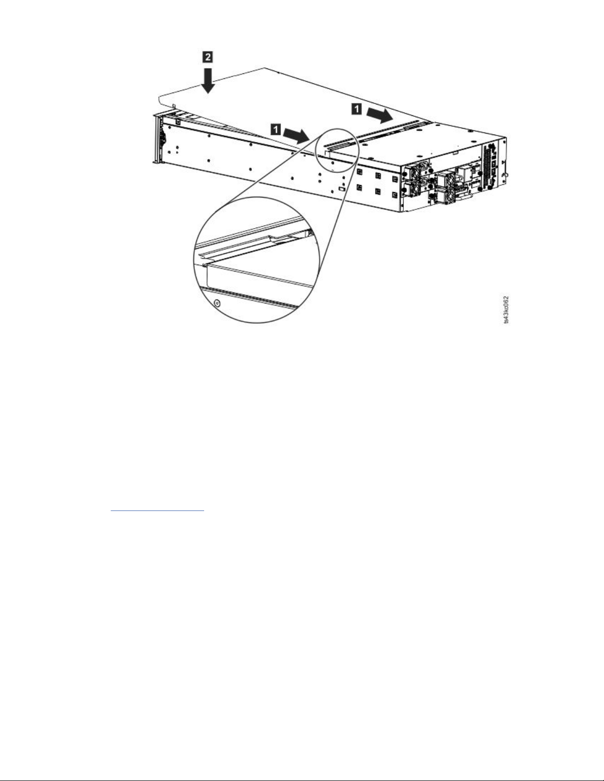
Figure 31. Lowering the front of the top cover
Installing Expansion Modules below the Base Module
If you are installing one or more Expansion Modules below the Base Module, move the bottom cover from
the Base Module to the Expansion Module that is installed at the bottom of the library
To move the library bottom cover plate from the Base Module to an Expansion Module
1. Remove the library bottom cover plate from the Base Module.
a. Place the Base Module on a work table.
b. Lift the unit front end by about 16 cm (use unit rear as a pivot edge).
c. Support the bottom cover with one hand. Insert a small flathead screwdriver or Torx screwdriver
into the hole and slide about 4 mm sidewards to the left to unlock the spring loaded lock. See
Figure 32 on page 42.
Important: Do NOT turn the module upside-down to complete this step.
Chapter 3. Installing
41
Page 74
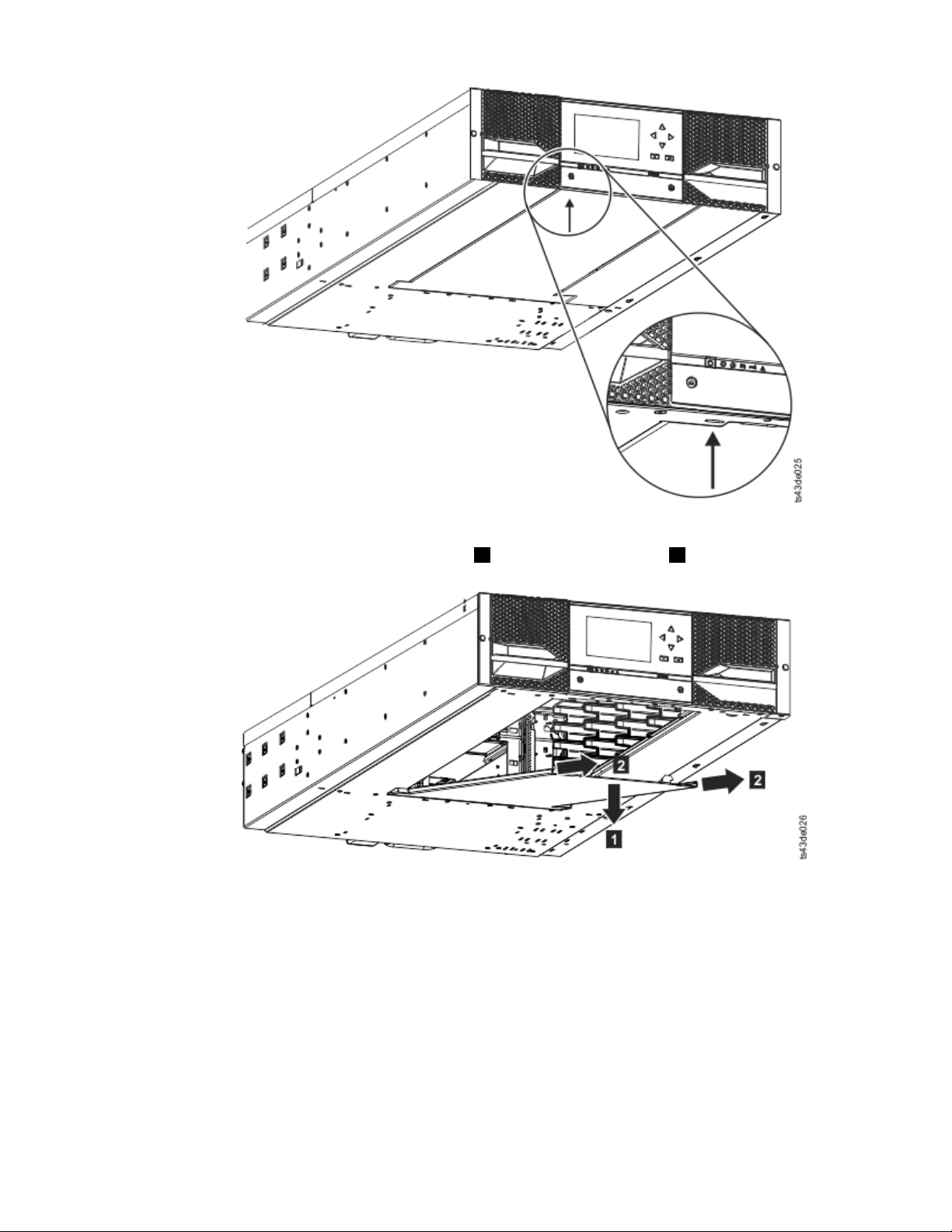
Figure 32. Unlocking the spring loaded lock
d. Lower the cover front end by about 10 cm ( 1 ) and pull gently forward ( 2 ) to disengage from the
pivot point at the unit center.
Figure 33. Removing the cover
2. Install the library bottom cover plate to an Expansion Module.
a. Place the Expansion Module on a work table.
b. Lift the unit front end by about 16 cm (use unit rear as a pivot edge).
c. Insert the bottom cover at the center
d. Lift the cover front edge until hard stop and it locks in at the unit front. The bottom cover ts only
one way.
42
Dell EMC ML3 Tape Library: User's Guide
Page 75

Figure 34. Lifting the cover and locking it
Installing modules in a rack
Rackmount installation procedure.
Modules are easy to install in racks that are compliant to the EIA 310A Standard, when at least 1 meter
deep. You need a #2 Phillips screwdriver for this process.
Note: Install modules from the bottom to the top. Refer to “Structure and supported library
congurations” on page 2 for the correct conguration of Base and Expansion Modules.
To locate the rail locations when multiple modules are installed.
1. Locate the bottom of the lowest full U where the lowest module is installed.
2. Continue identifying the locations for any additional module 3U higher.
To install the rails into the rack, starting from the lowest rack location.
a. Locate the four universal rack connectors, four Philips screws, and two rackmount rails (LH and
RH).
Note: The universal rack connectors have two sides, for round hole and square hole racks. The
square-hole side might be painted.
Figure 35. Universal rack connector
Chapter 3. Installing
43
Page 76
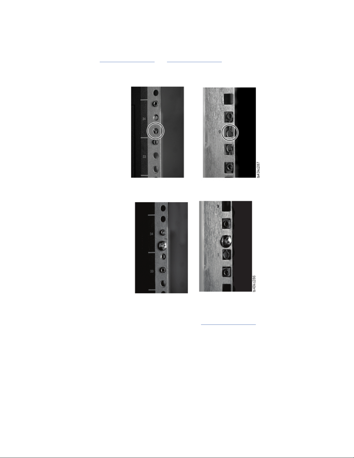
b. On the inside of the racks, facing out, mount the connectors at the appropriate height to the right
and left rack posts. Mount them in the middle hole of the height unit (the middle of a height unit is
the hole between two wide and neighboring division bars) in both front and back. The four screw
holes must align with the holes on your rack. If they do not, the blocks are not in the correct
location. See Figure 36 on page 44 and Figure 37 on page 44.
Note: If the connectors are installed incorrectly, the screws on the connectors do not match the
holes on the frames. The circles in the graphics highlight the mismatch.
Figure 36. Incorrect connector locations
Figure 37. Correct connector locations
c. Repeat step b on the right and left rack posts in the rear of the rack.
d. Mount the LH Rackmount rail to the connectors. See Figure 38 on page 45.
e. Repeat step d with the RH Rackmount Rail.
44
Dell EMC ML3 Tape Library: User's Guide
Page 77
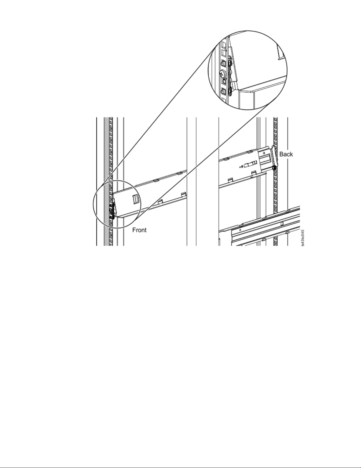
Figure 38. Mounting the rails to the connectors
Chapter 3. Installing
45
Page 78
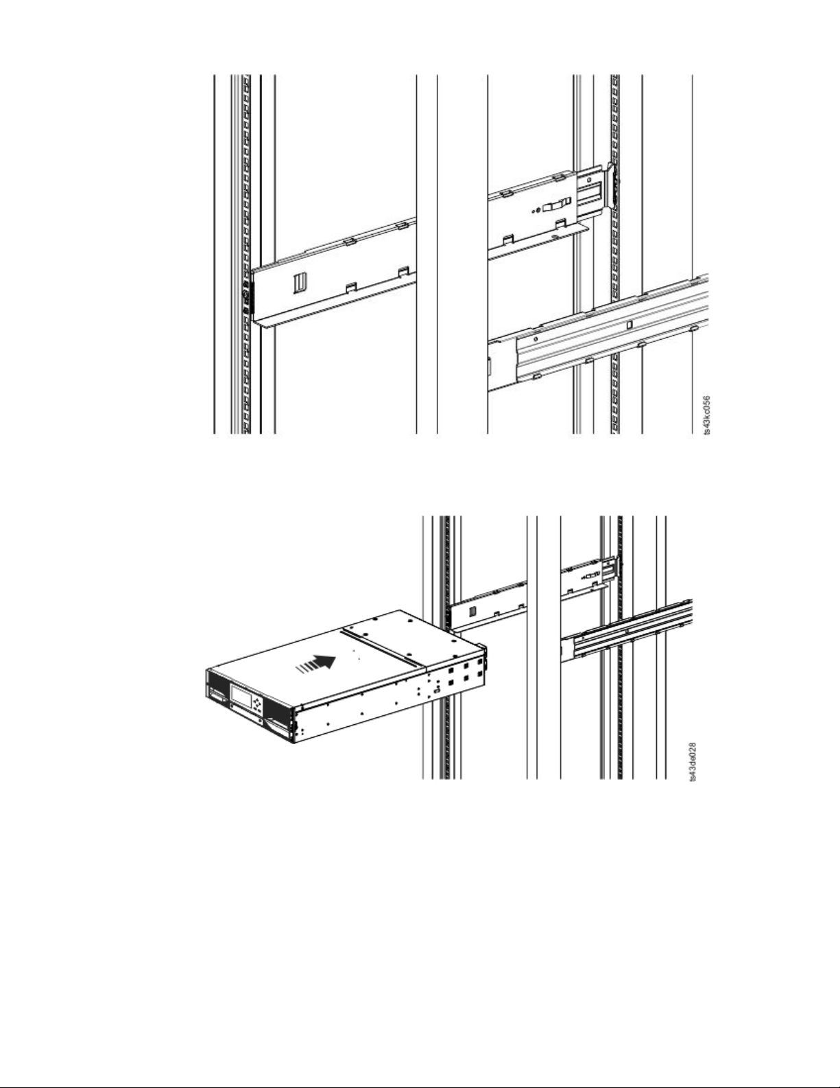
Figure 39. Side rails installed
3. Place the library at the front of the rack on the support angles of the rails and push it into the rack to
the back stop.
Figure 40. Sliding the library into the rack
4. If you are installing multiple modules, verify that this module is installed directly above or below its
adjacent module and is contained within the correct 3U volume. Remove the tape that is covering the
alignment pin lock/unlock lever on the rear of each module. The gap between modules must be less
than 4 mm.
46
Dell EMC ML3 Tape Library: User's Guide
Page 79
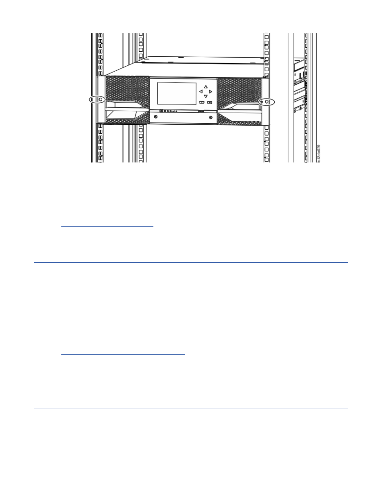
Figure 41. Library in the rack
Important: Each module must be on its own rails.
5. With a Phillips screwdriver, loosely screw the module to the front of the rack, one screw on each side.
See the circled areas in Figure 41 on page 47.
6. Align the module as needed. Then, tighten the screws on each side of the module. See “Aligning and
connecting modules” on page 47.
7. Repeat steps 2 - 6 to install the rest of the modules into the rack.
Installing a tabletop module
Installation of a one module library (Base Module only) can be completed without special hardware.
If you unpacked a Table Top Module, conrm that you received the following components:
1. Base Module
2. Accessory Kit
• One North American power cord
• One European power cord
1. Remove the Base Module from the box.
2. Open the cover and remove the foam packing from inside the enclosure. See “Unpacking the Base
Module and Expansion Modules” on page 36.
3. Replace the cover.
4. Set the Base Module in the wanted location. Ensure that it is level.
5. Plug in the power cord and the connecting cables.
Aligning and connecting modules
Aligning the modules ensures that the accessor can move freely between the modules.
Skip this step if the library does not have Expansion Modules.
Aligning the modules ensures that the accessor can move freely between the modules. The library cannot
operate unless the alignment mechanisms of the upper modules are in the locked position, and the
alignment mechanism of the lowest module is unlocked.
Chapter 3. Installing
47
Page 80

1. From the front of the library, loosen the screws on each of the modules where they are attached to the
rails two full turns.
2. From the back of the library, starting with the bottom pair of modules, align each module with the
module below it. Repeat for each pair of modules. Refer to Figure 44 on page 49.
a. Move the alignment lever of the upper of the pair of modules to the locked or engaged position. If
you encounter resistance, adjust the position of the upper module so the pin in the alignment
mechanism moves into the mating hole in the lower module. If you still encounter resistance, check
to see if the rack rails are installed correctly. Check that the hole for the alignment pin is on the left
rail (looking from the front) toward the back of the rack. See 1 in Figure 42 on page 48.
Figure 42. Hole for alignment pin
Note: If a blue alignment lever lock is attached to the rear of the module, slide it to the left, then
move the alignment lever. The lever lock has an internal spring, so hold it while the alignment lever
is moved, and it automatically springs back into place after the lever is moved. See Figure 43 on
page 48.
Figure 43. Alignment lever lock
48
Dell EMC ML3 Tape Library: User's Guide
Page 81

Figure 44. Alignment lever locked or engaged to lower module
Figure 45. Alignment lever unlocked or disengaged
3. Verify that the lowest module in the library has its alignment lever is in the unlocked or disengaged
position.
Chapter 3. Installing
49
Page 82

Figure 46. Two modules in rack, seen from the rear
1 Locked
2 Unlocked
4. From the front of the library, tighten the Philips screws on each of the modules to secure the modules
to the rack.
5. From the back of the library, connect the modules of each pair to its adjacent module by using the
expansion interconnect cables ( 1 ) as shown in Figure 47 on page 50.
Note: The top module's top connector and the bottom module's bottom connector has nothing
plugged into them.
Figure 47. Connected modules
Validating tape drive installation
• Half-height tape drives can be installed in any drive bay in a module.
• Full-height tape drives must be installed in the lowest two bays of a module. Installing a full-height
drive in the top two bays of a module is not supported.
50
Dell EMC ML3 Tape Library: User's Guide
Page 83

Connecting cables
Procedures to connect Fibre Channel, SAS, USB, and Ethernet cables.
Connecting Fibre Channel cables
1. Remove the FC port caps if necessary. Attach one end of the FC cable to port 0 on the tape drive.
Figure 48. Full-height FC dual port
Table 22. Full-height FC dual port
Number Description
1 FC port 0
2 FC port 1
3 Drive sled indicators (see Figure 18 on page 13)
Figure 49. Half-height FC single port
Table 23. Half-height FC single port
Number Description
1 FC port 0
2 Drive sled indicators (see Figure 18 on page 13)
2. Attach the other end of the FC cable to a switch or HBA.
3. Repeat the same process with port 1 if you have a dual port drive.
Connecting SAS cables
1. Attach the end of the SAS cable into the connector on the HBA. If you are using a SAS fanout/
Interposer cable, the end of the cable with only one connector must be plugged into the HBA.
Chapter 3. Installing
51
Page 84

2. Connect the drive end of the cable.
• If you are using a cable with a single connector on each end, attach the other end into the connector
on the tape drive.
• If you are using a SAS fanout/Interposer cable, attach one mini-SAS connector into the connector on
each tape drive. The unused ends of the SAS fanout/Interposer cable are single channel and not
suitable for use with disk arrays. Use the other ends to connect tape drives, or coil and secure them
to the rack to minimize stress on the connectors.
Figure 50. Half-height SAS dual port
Table 24. Half-height SAS dual port
Number Description
1 SAS port 0
2 SAS port 1
3 Drive sled indicators (see Figure 18 on page 13)
Note: SAS signal rates require clean connections between the HBA and tape drive. Do not use adapters or
converters between the HBA and the tape drive. For reliable operation, use a maximum SAS cable length
of 6 meters.
Connecting USB cables
Two USB ports are on the library, one in the front and one in the rear. USB connections are used by
service personnel for diagnostic and service procedures. Attach one end of the USB cable to your
notebook or other device and the other end to the front or rear USB port of the library.
Important: USB cable lengths of more than 3 meters are NOT supported for the front or rear USB ports.
Connecting Ethernet cables
To use the Management GUI, connect an Ethernet cable from the bottom Ethernet port on the Base
Module controller to your network. See “Rear panel” on page 8 for the location of the Ethernet ports.
Note: Ethernet port A (bottom Ethernet port) is the primary port. The second Ethernet port, Port B, is for
redundancy.
Powering on the library
Steps to power on the library.
1. Plug the power cables into the power connectors on each module and into power outlets.
Notes:
• The library has dual redundant power supplies. To increase redundancy, plug each power cord into a
different AC power circuit.
• A power supply is required in expansion modules if drives are installed.
52
Dell EMC ML3 Tape Library: User's Guide
Page 85
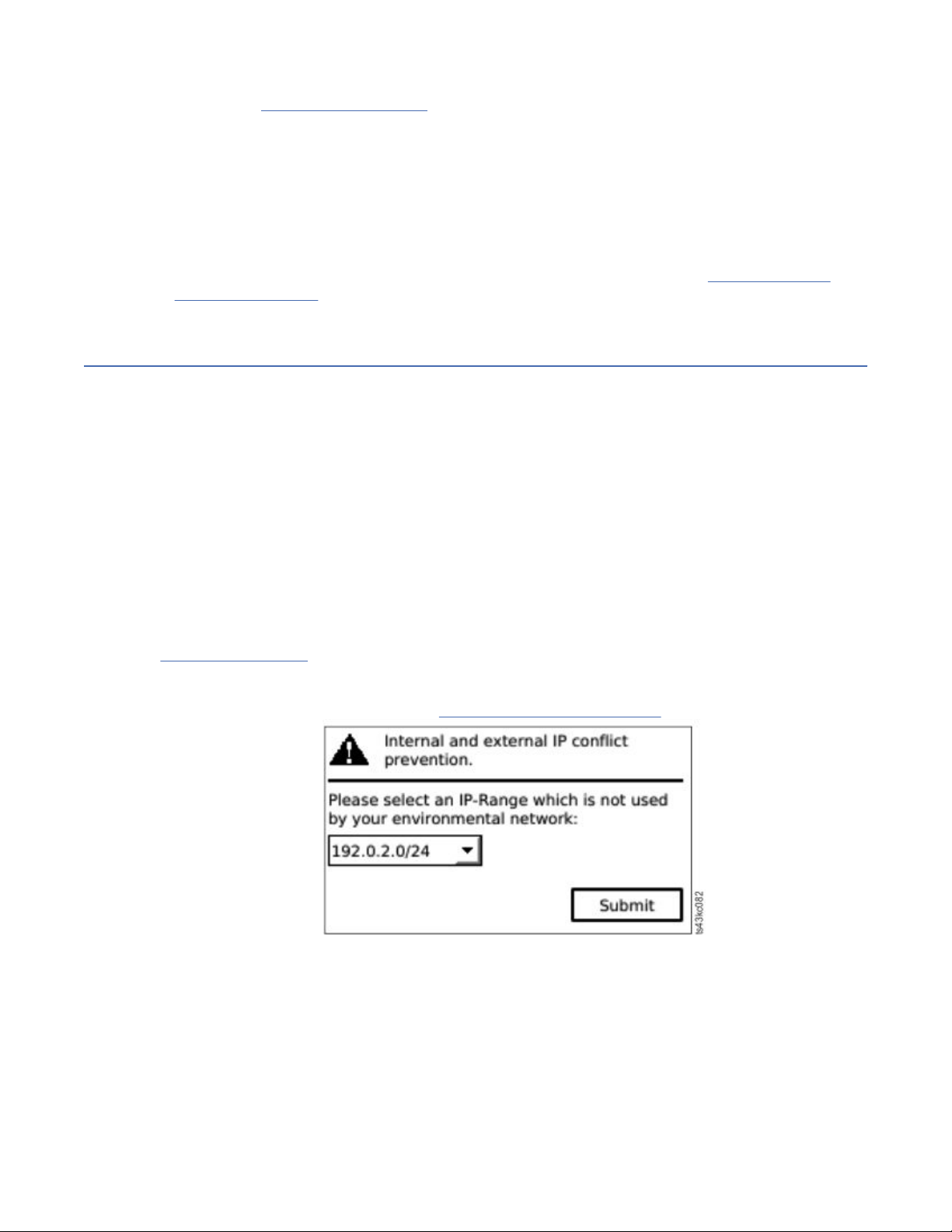
2. Power on the library by pressing Power on the Base Module just below the Operator Panel and hold for
5 seconds. See “Front panel” on page 7 for the location of the Power button. When the library is
powered on, it
a. Inventories the tape cartridges in the magazines,
b. Checks the rmware version on all modules,
c. Congures the tape drives.
d. Conrms the presence of the existing modules,
e. Searches for any new modules.
f. When the library is powered on for the rst time, the Initial Setup starts. See “The Initial Setup
process” on page 53.
The Initial Setup process
When you turn on the library for the rst time, the Initial Setup process starts automatically. Click Next
to start the process.
The wizard guides you through setting the Internal IP range, setting library network conguration,
conguring date and time, and setting the administrator PIN. You can skip items and stop the wizard at
any time. After you congure the network settings, you can start the wizard from the Management GUI to
complete more conguration items.
Notes on navigation and entering data into the Operator Panel
• The arrow keys on the front panel are used to select numeric and alphanumeric characters and
symbols. Capital and lowercase letters, numbers, and punctuation are available to use.
• The right button under the arrows is Enter, which is pressed before you enter text.
• The left button under the arrows is Back/Return, which is used to delete entries.
See Figure 55 on page 62
When the library starts up for the rst time, the initial setup automatically begins.
1. Enter the IP address for your library. See “IP range selection” on page 32.
Figure 51. IP address selection
2. Press Enter to unlock the Operator Panel.
.
Note: If you wait too long to make your selection, the unit auto calibrates. The auto calibration
nishes, then returns you to the login screen.
3. When you are logged in, the initial conguration process begins with Network Settings.
4. Follow the prompts to set date and time, and administrator PIN.
5. When the initial setup is complete, the display returns to the Operator Panel main screen.
Chapter 3. Installing
53
Page 86

To check your conguration at any time, go to Conguration > Initial System Setup on the Operator
Panel. On the Management GUI, go to Library.
Initial conguration and customization
After the physical installation and initial setup by using the Operator Panel is completed, an administrator
can log on to the Management GUI to complete the library conguration and conguration of any
additional features.
Upon the rst login with the user role administrator and password: adm001, you must change your
password. Your new password must have these characteristics:
• 8 characters long
• At least one lowercase alphabet character
• At least one uppercase alphabet character
• At least one numeric character
• No more than two consecutive characters
The Initial Conguration Wizard guides you through basic conguration settings.
The library has many features to customize it for your organization. Go to “Locating Management
functions” on page 63 to customize your library with these features.
• Enabling or disabling the I/O station.
• Naming the library with the Manage Logical Library function.
• Creating or managing Logical Libraries. See “Library sharing” on page 18 for information.
• Selecting Random or Sequential Mode. See “Random and Sequential Logical Library modes” on page 16
for information.
• Enabling and conguring SNMP network management.
• Setting up email event notication.
• Setting up encryption.
• Conguring date and time.
• Enabling or disabling Library Auto Clean. See “Methods of cleaning drives” on page 70.
Labeling and loading tape cartridges
The library can power on without cartridges, but needs cartridges before it can complete data read and
write operations, or any tests or operations that transfer cartridges.
Bar code labels are highly recommended in production environments to improve inventory time in the
library and ease cartridge-handling processes outside the library. See “Labeling tape cartridges” on page
160.
The I/O station
If the I/O station is enabled, you can use it to load cartridges into the library. Press the magazine button
for less than 3 seconds and after the button LED is flashing fast, pull out the I/O station.
54
Dell EMC ML3 Tape Library: User's Guide
Page 87

Figure 52. Open I/O station seen from the left
Bulk loading magazines
1. Unlock the magazine by pressing the magazine button for more than 3 seconds, wait for the button to
flash fast and then pull out the magazine.
a. From the Operator Panel or Management GUI, select the module and then select Open Magazine.
You can also press the release button on the front panel of the module to release the magazine.
b. Wait until the magazine is unlocked, and then pull out the magazine.
Note: Wait for the Operator Panel/Management GUI message to say the magazine is unlocked
before the magazine is pulled out.
Figure 53. Magazine pulled out
2. Load the tape cartridges into the magazine.
Chapter 3. Installing
55
Page 88

Important: For libraries with serial numbers before 7800K0K, the slots of the lowest row of the
bottom module are inaccessible and can contain a 4-slot I/O station only, so do not load cartridges
into these slots.
3. Insert the magazine into the unit.
4. Push the magazine handle slowly until the magazine release latch snaps into place. The magazine
locks into place.
Important: Push the magazine fully into place until the latch snaps into place.
5. Repeat steps 1 - 3 for each of the other magazines.
See “Accessing cartridges” on page 71.
Verifying the installation
Verify that the library has the current rmware revision, and save the conguration settings. This action
can be helpful if the library requires service.
Verify that the library has the current rmware revision. The library rmware revision is displayed at
Library > Actions > Properties.
1. Verify library rmware and update if needed: Library > Actions > Update Library Firmware
2. Run Library Verify.
3. Save the conguration settings to a le on your computer from the Management GUI: Settings >
Library > Advanced > Save Conguration File.
Having a backup of the library conguration is helpful when the library is recovering from a
conguration error or needs service.
Advanced library conguration
To create and manage multiple logical libraries, utilize the advanced logical library function.
Overview
Overview of advanced features such as multipath architecture, multiple logical libraries, and multiple
control paths.
Multipath architecture
The multipath architecture feature of this tape library allows Open Systems applications to share the
robotics of the library. See “Library sharing” on page 18
The library features storage area network (SAN) ready multipath architecture. This architecture allows
homogeneous or heterogeneous Open Systems applications to share the library's robotics without
middleware or a dedicated server (host) acting as a library manager. The SAN-ready multipath
architecture makes sharing possible by partitioning the library's storage slots and tape drives into logical
libraries. Servers can then run separate applications for each logical library. This partitioning capability
extends the potential centralization of storage that the SAN enables. Partitioning also provides
investment protection if your application does not support the mixing of drive generations and media in
the same logical library.
.
The multipath architecture of this library is designed to provide the capability to share the library robotics.
The sharing is accomplished rst by partitioning the library into multiple logical libraries (up to the
number of drives installed). Then, each logical library is assigned its own separate and distinct drives,
storage slots, and control paths. Input/output (I/O) slots are shared on a rst-come-rst-serve basis. This
type of partitioning is designed to allow heterogeneous applications to share the library robotics
independent of each other. Cartridges under library control are not shared between logical libraries, nor
are they allowed to be moved between logical libraries. An example of heterogeneous sharing is a
56
Dell EMC ML3 Tape Library: User's Guide
Page 89

Microsoft Windows application that is using the drive and storage slots of one logical library, while a UNIX
application uses the drive and slots of another logical library. See “Mixed drives” on page 12.
Multiple logical libraries
A library can be partitioned into multiple logical libraries to enable simultaneous data backup and restore
tasks from different applications. For example, you can create multiple logical libraries so that is
processes
• Commands from Application 1 (about Department A) in Logical Library 1
• Commands from Application 2 (about Department B) in Logical Library 2
• Commands from Application 3 (about Department C) using Sequential Mode in Logical Library 3
In this conguration, the tape drives and cartridges of each logical library are dedicated to that library and
are not shared among other libraries and applications. Commands that are issued by the applications
travel to the library through unique control paths or sequential mode processing by the library. So, the
data processing for Department A is conned to the tape drives and cartridges of Logical Library 1.
Processing for Department B is conned to the tape drives and cartridges of Logical Library 2, and so
forth.
For applications that do not support mixed drive types and media within the same logical library,
partitioning the library into multiple logical libraries provides the capability to keep them separate. For
example, you can partition the following tape drives and their media into multiple and separate logical
libraries:
• LTO 8
• LTO 7
• LTO 6
Multiple control paths
With this tape library's multipath architecture, in addition to creating multiple logical libraries, you can
congure any logical library to have more than one control path. A control path is a logical path into the
library through which the library receives standard SCSI Medium Changer commands to control the
library operations.
Note: No SCSI Medium Changer is congured when the logical library is enabled as Sequential Mode
Multiple control paths reduce the possibility of a failure in one control path to cause the entire library to
become unavailable. Also, when you congure more control paths, more library-sharing congurations
and options are possible. Access to the library is on a rst-come, rst-served basis. Each control path for
a logical library can accept commands while the library is in use by another control path.
Multiple control paths for control path failover
This tape library offers an optional control path failover feature. See “Library sharing” on page 18
“Control path failover, Data path failover, and load balancing” on page 18.
Use of the control path failover feature further reduces the possibility of a failure in one control path to
cause the entire library to become unavailable.
The control path failover feature (feature code 1682) enables the host device driver to resend a command
to a different control path for the same logical library.
Library partitioning
Libraries that contain at least two drives can congure two logical libraries. It is possible to congure up
to 21 logical libraries in the library (up to the number of drives installed). In a partitioned library, the
Operator Panel reports only the status of logical library 1 in the main menu because of space limitations.
The user must go to the logical libraries status in the Operator Panel to get the information about the
additional library partitions. The Management GUI provides a Logical Library Graphical View.
and
Chapter 3. Installing
57
Page 90

Partitioning of libraries
With full-height or half-height physical drives, physical numbering is bottom up for all drives. For example,
if you replace a half-height drive in Figure 22 on page 15, the drives are still numbered 1-4. If you add a
drive in any of the slots in between drives numbered 1 and 4, the physical numbering changes and is still
numbered bottom up.
Important: A full-height drive can be installed in a module in the lower two slots only.
Conguration of a 1-logical library system
A one logical library system contains all drives present in any drive positions, and it contains all the slots.
Conguration of multiple logical libraries
A library with multiple logical libraries must have a drive for each logical library and at least ve slots.
Drives can be in any location in the library. It is best to have drives that are located near the slots that are
assigned to the same logical library to minimize accessor movement and maximize performance.
SCSI element-addressing
A logical library assigns SCSI element addresses to drives, storage slots, I/O slots, and the accessor. For
each element type (drive, storage, I/O), the SCSI element address can be viewed on the Management
GUI.
While SCSI addressing follows the same method as physical location-numbering, this action depends on
the Advanced Logical Library conguration.
Drive numbering is from bottom to top. Storage slot-numbering is from left magazine (front to back,
bottom to top) to right magazine (back to front, bottom to top). IO slot-numbering is from bottom to top.
Accessor is single number.
Note: When the number of drives in your library are reduced, update the logical library conguration. This
action removes all event notications that indicate a drive is missing.
Updating the logical library conguration might change the SCSI element addressing.
Verifying the host connection
Procedure to verify the connection between the host computer and the library.
To verify the connections between the host computer and the library
1. Install the application software and drivers that are compatible with the library. Backup software
packages might require extra software or licensing to communicate with the robotics.
2. Verify the connection between the library and the host by using the host server’s operating system
utilities. Or, use the Tape Diagnostic Tool (ITDT) to verify the communication between library and host.
See “The ITDT rmware update, dump retrieval and drive test tool ” on page 80.
See “Host connectivity” on page 20 for compatible servers and software.
58
Dell EMC ML3 Tape Library: User's Guide
Page 91

Chapter 4. Managing
Four user roles are described, and each user role has its specic functions.
• Administrator - This role provides access to the administrator functions on the Management GUI.
There is a default administrator password adm001 for the rst login. The administrator password can be
changed on the Local Users page.
• Monitor - This role allows access to library status information and does not allow access to
conguration, maintenance, or operation features. Setting a monitor password restricts access to status
information to only those users who know the monitor password. Passwords for the Monitor role can be
set or changed by the administrator.
• Superuser - This role has same access rights as the Administrator role, except the ability to access the
Local Users and Remote Authentication (LDAP Authentication and Kerberos Authentication) pages.
In addition, it is possible to do cartridge moves and open magazines and I/O Stations. Passwords for the
Superuser role can be set or changed by the administrator.
• Service - This role provides access to the service functions on the Management GUI. Passwords for the
Service role can be set or changed by the administrator.
Notes:
• Monitor, Superuser, and Service user IDs must be enabled by the library administrator. These accounts
are disabled by default.
• For a complete description of the menu items available to each user role, see Appendix B,
“Management GUI functions and roles ,” on page 151.
The Management GUI
With the Management graphical user interface (GUI), you can monitor, congure, and operate most library
functions from a web browser.
When possible, use the Management GUI as the primary library interface. The web interface provides
access to more features, includes online help, and is intuitive to use.
Before the Management GUI can be used, you need to log in and congure the library network settings
with the Operator Panel. This action can be done during Initial Setup. See “The Initial Setup process” on
page 53.
Logging in with the Management GUI
1. Open a supported web browser and enter the IP address of the library in the browser’s address bar.
2. Type in the username (administrator or other administrator-created user) and the password. Click
Login.
Note: For initial login, type administrator and the password adm001. You must change the
password after the initial login. Your new password must have these characteristics:
• 8 characters long
• At least one lowercase alphabet character
• At least one uppercase alphabet character
• At least one numeric character
• No more than two consecutive characters
Note: Only one person (on Operator Panel or Management GUI) can be logged in to the library at a time. If
another person is already logged in when you try to log in, a dialog box appears asking if you want to log
off the other user.
Page 92
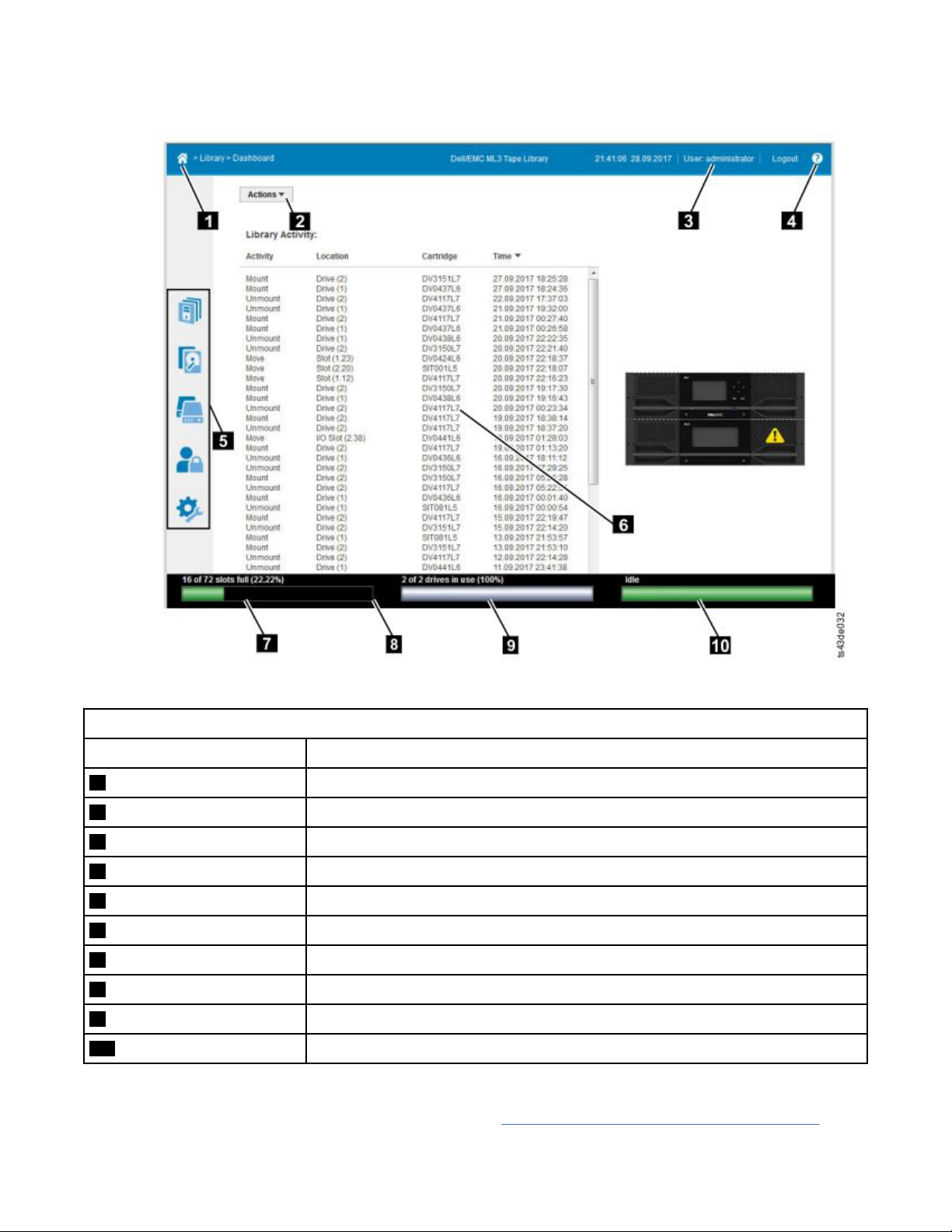
The Library main screen on the Management GUI
The library main screen is organized into the following regions:
Figure 54. Management GUI main screen
Table 25. Main screen elements
Element
1 Home icon > Current Navigation
2 Actions > dependent on current navigation
3 User logged in
4 Help
5 Navigation Dock
6 Overview - dependent on current navigation
7 Physical Capacity
8 Status Bar
9 Drive Activity
10 Library Status
Tips:
1. For specic management function navigation, see “Locating Management functions” on page 63.
60
Dell EMC ML3 Tape Library: User's Guide
Page 93
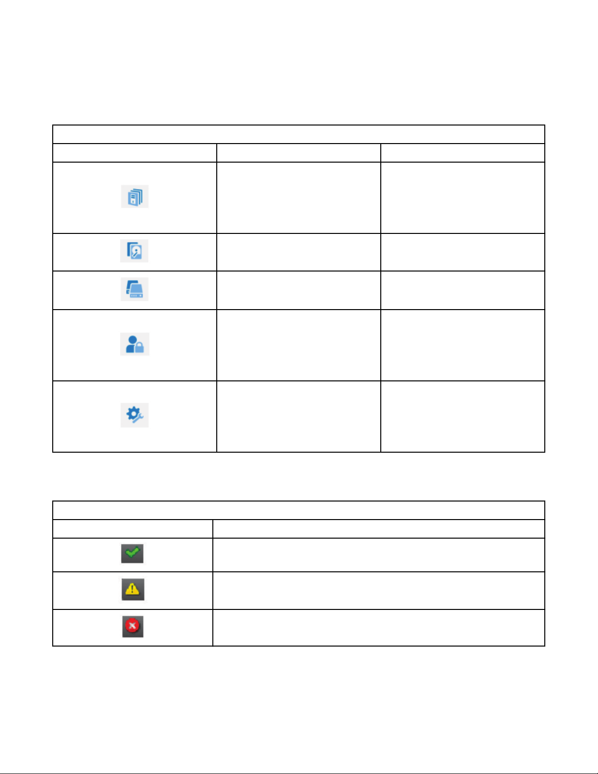
2. Check the online help in the Management GUI for additional information. The help pages are updated
with rmware updates and often contain up-to-date technical details that might not be contained in
this document. To access Management GUI help, click ? on the right side of the Management GUI top
banner.
Navigation Dock
Table 26. Navigation Dock
Navigation Dock Icons Element Extra menus
Library
Drive Drives and Ports
Cartridges Cartridges and Slots
Access
Settings
• Dashboard
• Modules and Magazines
• Logical Libraries
• Events
• Local Users
• Local Password Policies
• LDAP Authentication
• Kerberos Authentication
• Library
• Network
• Notications
• Security
Status icons
Status icons indicate the following conditions.
Table 27. Status icons
Icon Description
The green OK icon indicates that the library is fully operational and that no
user interaction is needed.
The yellow exclamation point Warning icon indicates that user attention
is necessary, but that the device can still nish most operations.
The red X Error icon indicates that user intervention is needed and that
the device can’t nish some operations.
Chapter 4. Managing 61
Page 94

The Operator Panel
With the Operator Panel, you can monitor, congure, and operate library functions from the library front
panel.
The Operator Panel has a Power button, an LCD display, six navigation buttons, and ve LEDs. To use the
Operator Panel, you must use the six navigation buttons (up/down, left/right, Enter, Back). The Operator
Panel is not a touchscreen. See “Front panel” on page 7 for the location of the navigation buttons.
Operator Panel screens
Figure 55. Operator Panel main screen
Operator Panel main screen layout
• Left Pane - Displays the library status (rmware revision, number of modules, number of slots, number
of drives, number of errors, number of warnings.
• Center Pane - Provides access to operate, congure, and log out of the library and to view more status
information (Operation, Conguration, Maintenance, Status).
• Bottom Pane - Displays more status information (library status, time/date, IPv4, or IPv6 address). The
status pane displays one status information for 10 seconds and then switches to the next status item.
Table 28. Operator Panel menu tree
Operation Conguration Maintenance Status Logout
Move Cartridge
from Drive
to Home Slot
Move Cartridge
The Operator Panel provides a subset of menu items that are compared to the full capability of the
Management GUI. For the operations that are available on the Operator Panel, see “Locating Management
functions” on page 63.
Accessing the library with the Operator Panel
The Operator Panel can be accessed in two ways, with a PIN or without one.
1. If the Operator Panel screen saver is on, press Enter.
2. If no PIN is congured, press Enter.
Initial System Setup
Date & Time
Network Settings
User Accounts
Reset
Library Tests
View Events
Drive Service Logs
Download
Library Logs
Download
Drive Firmware
Upgrade
Library Firmware
Upgrade
LCD Adjustment
Network Settings
Library
Drive
Logout
62
Dell EMC ML3 Tape Library: User's Guide
Page 95
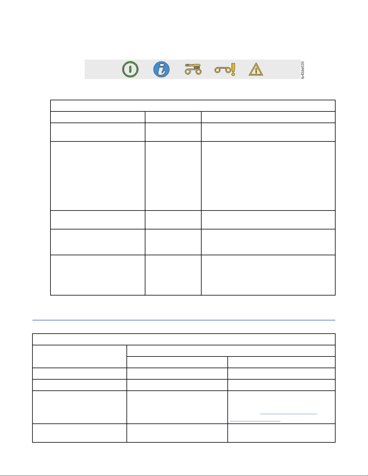
3. If a PIN is congured, enter the PIN, then select Login and press Enter.
Status icons
Figure 56. Front panel LEDs
Table 29. Front panel LEDs
LEDs Color Descriptions
Ready Green Steady when power is on, flashing with tape
Ready drive or library robotic activity.
Unit ID Blue when
activated
Clean Amber On, when a tape drive-cleaning operation is
Attention Amber Flashing if the library detected a condition for
Error Amber On, if an unrecoverable tape drive or library
Locating Management functions
The unit identication (UID) LEDs are controlled
by the user through the Maintenance > UID
LED Control screen. The UIDs on the Operator
Panel and base module back panel are
activated and deactivated together. In addition,
UIDs on drives and expansion module back
panels can be activated separately. The UIDs
are helpful for locating components of the
library in a data center.
recommended.
which user attention is necessary, but the
library can still complete most operations.
error occurs. A corresponding error message is
displayed on the LCD screen. User intervention
is required as the library is not capable of
completing some operations.
This table provides the menu navigation to assist with library setup and conguration.
Table 30. Locating Management functions
Task Menu Navigation
Operator Panel Management GUI
Advanced settings Not available with this interface Settings > Library > Advanced
Auto Calibration Not available with this interface Settings > Library > Auto Calibration
Auto Clean Not available with this interface Library > Logical Libraries > Actions
> Manage Logical Library (Expert
Mode) See “Methods of cleaning
drives” on page 70.
Cartridge, eject from a drive Operation > Move Cartridge from
Drive to Home Slot
Drives > Actions > Eject Cartridge
from Drive
Chapter 4. Managing 63
Page 96

Table 30. Locating Management functions (continued)
Task Menu Navigation
Operator Panel Management GUI
Cartridge Inventory, rescan Not available with this interface Cartridges > Actions > Inventory
Library
Cartridges, list Not available with this interface Cartridges
Cartridges, move Operation > Move Cartridge Cartridges > Actions > Move
Cartridges
Cartridges, graphical view Not available with this interface Cartridges > Actions > Graphical
View
Certicates, create, backup,
restore
Cleaning, tape drive Not available with this interface Drives > Actions > Clean Drive See
Conguration, save and restore Not available with this interface Settings > Library > Advanced
Conguration, reset Not available with this interface Settings > Library > Advanced
Conguration le, restore Not available with this interface Settings > Library > Advanced
Conguration le, save Not available with this interface Settings > Library > Advanced
Date and time, congure Conguration > Date & Time Settings > Library > Date and Time
Diagnostics, run Demo Mode Maintenance > Library Tests Library > Actions > Tests
Diagnostics, run Library Verify Not available with this interface Library > Actions > Tests
Diagnostics, run Drive test Maintenance > Library Tests Library > Actions > Tests
Diagnostics, run Slot to Slot
exerciser
Drive rmware, update Maintenance > Drive Firmware
Not available with this interface Settings > Security > GUI
“Methods of cleaning drives” on page
70.
Not available with this interface Library > Actions > Tests
Drive > Actions > Update Drive
Upgrade (requires FAT32 format
USB drive)
Firmware
Drives and Modules, reset the list Not available with this interface Settings > Library > Advanced
Drive status Status > Drive Drives
Drive service logs, download Maintenance > Drive Service Logs
Download (requires FAT32 format
USB drive)
Drive, modify port settings Not available with this interface Drives > Actions
Email Notication Not available with this interface Settings > Notications
Encryption, congure Not available with this interface Settings > Security > Encryption See
Encryption Connectivity Check Not available with this interface Settings > Security > Encryption
Encryption, reset Not available with this interface Settings > Security > Encryption
64 Dell EMC ML3 Tape Library: User's Guide
Drives > Actions
“Conguring Library Managed
Encryption” on page 72.
Page 97

Table 30. Locating Management functions (continued)
Task Menu Navigation
Operator Panel Management GUI
Factory/Manufacturing reset Conguration > Reset > Full
Factory Reset
Help Not available with this interface Click the ? at the upper right of the
Identier light, turn On or Off Not available with this interface Library > Actions > Turn Identier
Initial Setup Conguration > Initial System
Setup
Inventory List Not available with this interface Cartridges
I/O Station, enable or disable Not available with this interface Library > Modules and Magazines >
I/O Station, open See “Accessing cartridges” on page
71.
Kerberos Authentication,
congure
Key Path Diagnostic Not available with this interface Settings > Security > Encryption See
Not available with this interface Access > Kerberos Authentication
Settings > Library > Advanced
Management GUI screen. See 4 on
Figure 54 on page 60.
Light On or Off
Settings > Library > Initial
Conguration Wizard
Actions > Enable or Disable I/O
Station
Library > Modules and Magazines >
Actions > Unlock I/O Station
“Key Path Diagnostics” on page 74.
LCD Adjustment Maintenance > LCD Adjustment Not available with this interface
LDAP Authentication, congure Not available with this interface Access > LDAP Authentication
Library rmware, update Maintenance > Library Firmware
Upgrade (requires FAT32 format
USB drive)
Library logs, download Maintenance > Library Logs
Download (requires FAT32 format
USB drive)
Library logs, view or clear Maintenance > View Event Ticket
Logs
Library Information Status Library > Actions
Library Managed Encryption,
congure
Library Verify, run Maintenance > Library Tests Library > Actions > Tests > Library
List of Known Drives and
Modules, reset
Logical Libraries, graphical view Not available with this interface Library > Logical Libraries > Actions
Not available with this interface Settings > Security > Encryption See
Not available with this interface Settings > Library > Advanced
Library > Actions > Update Library
Firmware
Library > Actions > Export Library
Logs
Library > Events > Actions
“Conguring Library Managed
Encryption” on page 72.
Verify
> Graphical View
Chapter 4. Managing 65
Page 98

Table 30. Locating Management functions (continued)
Task Menu Navigation
Operator Panel Management GUI
Logical Libraries, Manage (Basic
Mode)
Logical Libraries, Manage (Expert
Mode)
Logical Libraries, Mode congure Not available with this interface Library > Logical Libraries > Actions
Logical Libraries, Mode status Not available with this interface Library > Logical Libraries
Magazines, open See “Accessing cartridges” on page
Network settings Conguration > Network Settings Settings > Network > Ethernet
Notications, congure Not available with this interface Settings > Notications
Operator Panel, session lock
timeout
Password Policy Not available with this interface Access > Local Password Policies
Not available with this interface Library > Logical Libraries > Actions
> Manage Logical Library (Basic
Mode)
Not available with this interface Library > Logical Libraries > Actions
> Manage Logical Library (Expert
Mode)
> Manage Logical Library (Basic
Mode) or Manage Logical Library
(Expert Mode) See “Random and
Sequential Logical Library modes” on
page 16.
Library > Modules and Magazine >
71.
Not available with this interface Settings > Security > GUI
Actions > Unlock Magazine
Path Failover license key, add or
delete
Port Settings, modify Not available with this interface Drives > Actions > Modify Port
Remote Logging (rsyslog),
congure
Reset, rediscover devices Not available with this interface Settings > Library > Advanced
Reset Internal IP Range Conguration > Reset > Reset
Reset Library Not available with this interface Library > Actions > Reset Library
Reset Drive Not available with this interface Drives > Actions > Reset Drive
Sequential mode, congure Not available with this interface Library > Logical Libraries > Actions
SNMP, congure Not available with this interface Settings > Notications > SNMP
SNTP (Simple Network Time
Protocol) Synchronization,
congure
Not available with this interface Settings > Library > Licensed
Features
Settings
Not available with this interface Settings > Notications > Remote
Logging (rsyslog)
Not available with this interface
Internal IP Range
> Manage Logical Library (Basic
Mode) or Manage Logical Library
(Expert Mode) See “Random and
Sequential Logical Library modes” on
page 16.
Not available with this interface Settings > Library > Date and Time >
SNTP (Simple Network Time
Protocol) Synchronization
66 Dell EMC ML3 Tape Library: User's Guide
Page 99

Table 30. Locating Management functions (continued)
Task Menu Navigation
Operator Panel Management GUI
SSL, enable or disable Not available with this interface Settings > Security > GUI > Secure
Communication
Session Timeout Not available with this Interface Settings > Security > GUI > Session
Timeout
Time Zone, set Not available with this interface Settings > Library > Date and Time >
Time Zone
Unlabeled Media, allow Not available with this interface Settings > Library > Advanced
Users, Access recovery Conguration > User Accounts Not available with this interface
Users, Modify User Passwords Not available with this interface Access > Local Users > Actions >
Modify User Passwords
Users, Modify Role Permissions Not available with this interface Access > Local Users > Actions >
Modify Role Permissions
Users, Modify Operator Panel
PIN
Users, Add Not available with this interface Access > Local Users > Add User For
Users, Remove Not available with this interface Access > Local Users > Actions >
Conguration > User Accounts Access > Local Users > Actions >
Modify Operator Panel PIN
information about different roles, see
Chapter 4, “Managing,” on page 59.
Remove User
Default settings
The library is set to default settings when rst purchased. Many of these settings can be customized.
Table 31. Default settings
Parameter Default Conguration
Reset Default
Settings
User Accounts
Administrator login
Local user accounts
User = administrator
Management GUI Password = adm001
Local Default Users = administrator
Number of Custom User = 0
NOT reset
x
User Account Settings
Chapter 4. Managing 67
Page 100

Table 31. Default settings (continued)
Parameter Default Conguration
Reset Default
Settings
Password rules
Management GUI Restricted
Login
Allow I/O Station/Magazine
access by monitor role
Session Locking Disabled x
Remote Authentication
(LDAP) Conguration
Network conguration (eth0)
Host name Blank NOT reset
IP address (dhcp) NOT reset
Min. number of characters
Min. number of uppercase alphabetic characters
Min. number of lowercase alphabetic characters
Min. number of numeric characters
Min. number of special characters
Max. number of identical consecutive characters
Max. number of failed logins
Max. number of days before PW must be changed
Number of PW changes before it can be used again
Disabled x
Disabled x
Disabled NOT reset
8
1
1
1
0
2
3
90
3
x
Subnet mask (dhcp) NOT reset
Default gateway (dhcp) NOT reset
Auto Negotiate Enabled NOT reset
Speed Auto NOT reset
IPv4 Enabled NOT reset
DHCPv4 Enabled NOT reset
IPv6 NOT reset
IPv6 Prex Enabled NOT reset
Static v6 Disabled NOT reset
IPv6 Method Disabled NOT reset
DHCPv6 Disabled NOT reset
DNS1 and DNS2 Conguration
for IPv4
DNS1 and DNS2 Conguration
for IPv6
Network Access Services
Primary Network Interface
(eth0)
(dhcp) NOT reset
Disabled NOT reset
Enabled NOT reset
68 Dell EMC ML3 Tape Library: User's Guide
 Loading...