

Page 1

'HOO2SWL3OH[*;D0LQL7RZHU6\VWHPV
:LWK(QKDQFHG0DQDJHDELOLW\(0
5()(5(1&($1',167$//$7,21*8,'(
®
Page 2

Information in this doc um ent is subject to change without notice.
1997 Dell Computer Corporation. All rights reserved.
Reproduction in any m an ner whatsoever without the wri tt en permission of Dell Computer Corporation is strictly for bidden.
Trademarks used in this text: Dell, OptiPlex, and the DELL logo are registered tradem arks and DellWare is a registered service mark of Dell
Computer Corporation; Intel and Pentium are registered trademarks and MMX is a trademark of Intel Corporation; Microsoft, MS-DOS, Windows,
and Windows NT are registered tr ademarks and Windows for W orkgr oups is a trademark of Microsoft Corporation; IBM and OS/2 are register ed
trademarks of International Business Machines Corporation; 3Com is a registered trademark of 3Com Corporation; VESA is a registered trademark
of Video Electronics Standards Association; UNIX is a registered trademark of UNIX System Laboratories, Inc., a wholl y owned subsidiary of
Novell, Inc. As an Energy Star Partner, Dell Computer Corporation has determined that this product meets the Energy Star guidelines for energy
efficiency.
Other trademarks and trade names may be used in this document to refer to either the ent it ie s claiming the marks and na mes or their products.
Dell Computer Corporation disclaims any pro pri etary interest in trademarks and trade names other than its own.
November 1997 P/N 88763
Page 3

Safety Instructions
U
se the following safety guidelines to help protect
your computer system from potential damage and to
ensure your own personal safety.
W
hen Using Your Computer
System
As you use your comput er s yst em, o bs erve the following
safety guidelines:
•
To help avoid damaging your computer, be sure the
voltage selection switch on the power supply is set to
match the alternating current (AC) power available
at your location:
— 115 volts (V)/60 hertz (Hz) in most of Nort h and
South America and some Far Eastern countries
such as Japan, South Korea, and Taiwan
— 230 V/50 Hz in most of Europe, the Middle
East, and the Far East
Also be sure your monitor and attached peripherals
are electrically rated to operate with the AC power
available in your location.
•
To help avoid possible damage to the system board,
wait 5 seconds after turning off the system before
removing a component from the system bo ard or disconnecting a peripheral device from the computer.
•
To help prevent electric shock, plug the computer
and peripheral power cables into properly grounded
power sources. These cables are equipped with
three-prong plugs to help ensure proper grounding.
Do not use adapter plugs or remove the grounding
prong from a cable. If you must use an extension
cable, use a three-wire cable with properly grounded
plugs.
•
To help protect your computer system from sudden,
transient increases and decreases in electrical power,
use a surge suppressor, line conditioner, or uninterruptible power supply (UPS).
•
Be sure nothing r ests on your compu t er system’s
cables and that the cables are not located where they
can be stepped on or tripped over.
•
Do not spill food or liquids on your computer. If the
computer gets wet, consult your Diagnostics and
Troubleshooting Guide.
•
Do not push any objects into the openings of your
computer. Doing so can cause fire or electric shock
by shorting out interior components.
•
Keep your computer away from radiators and heat
sources. Also, do not block cooling vents. Avoid
placing loose papers underneath your computer; do
not place your computer in a closed-in wall unit or
on a bed, sofa , or rug.
E
rgonomic Computing Habits
WARNING: Improper or prolonged keyboard use
may result in injury.
For comfort and efficiency, observe the following ergonomic guidelines when setting up and using your
computer system:
•
Position your system so that the monitor and keyboard are directly in front of you as you work.
Special shelves are available (from Dell and other
sources) to help you correctly position your
keyboard.
v
Page 4

•
Set the monitor at a comfortable viewing distance
(usually 510 to 610 millimeters [20 to 24 inches]
from your eyes).
•
Make sure the monitor screen is at eye level or
slightly lower when you are sitting in front of the
monitor.
•
Adjust the tilt of the monitor, its contrast and brightness settings, and the lighting around you (such as
overhead lights, desk lamps, and the curtains or
blinds on nearby windows) to minimize reflections
and glare on the monitor screen.
•
Use a chair that provides good lower back support.
•
Keep your forearms horizontal with your wrists in a
neutral, comfortable position while using the keyboard or mouse.
monitor screen at or below eye level
wrists relaxed and flat
•
Always leave space to rest your hands while using
the keyboard or mouse.
•
Let your upper arms hang naturally at your sides.
•
Sit erect, with your feet resting on th e flo or and your
thighs level.
•
When sitting, make sure the weight of your legs is on
your feet and not on the front of your chair seat.
Adjust your chair’s height or use a footrest, if necessary, to maintain proper posture.
•
Vary your work activities. Try to organize your work
so that you do not have to type for extended periods
of time. When you stop typing, try to do things that
use both hands.
monitor and keyboard
positioned directly
in front of user
arms at desk level
vi
feet flat on the floor
Page 5

W
hen Working Inside Your
Computer
component such as a microprocessor chip by its
edges, not by its pins.
Before you remove the computer cover, perform the following steps in the sequence indicated.
CAUTIONS: Do not attempt to service the computer system yourself, except as explained in this
guide and elsewhere in Dell documentation. Always
follow installation and service instructions closely.
To help avoid possible damage to the system board,
wait 5 seconds after turning off the system before
removing a component from the system board or
disconnecting a peripheral device from the
computer.
1. Turn off your computer and any peripherals.
2. Disconnect your computer and peripherals from
their power sources. Also, disconnect any telephone or telecommunication lines from the
computer.
Doing so reduces the potential for personal injury or
shock.
3. T ouch an unpainted metal surface on the chassis,
such as the metal around the card-slot openings
at the back of the computer, before touching anything inside your computer.
While you work, periodically touch an unpainted
metal surface on the computer chassis to dissipate
any static electricity that might harm internal
components.
In addition, take note of these safety guidel ines when
appropriate:
When you disconnect a cable, pull on its connector
•
or on its strain-relief loop, not on the cable itself.
Some cables have a connector with locking tabs; if
you are disconnecting this type of cable, press in on
the locking tabs before disconnecting the cable. As
you pull connectors apart, keep them evenly aligned
to avoid bending any connector pins. Also, before
you connect a cable, make sure both connectors are
correctly oriented and aligned.
Handle components and cards with care. Don’t touch
•
the components or contacts on a card. Hold a card by
its edges or by its metal mounting bracket. Hold a
WARNING
There is a danger of a new battery exploding if it is
incorrectly installed. Replace the battery only with
the same or equivalent type recommended by the
manufacturer. Discard used batteries according to
the manufacturer’s instructions.
P
rotecting Against Electrostatic
Discharge
Static electricity can harm delicate components inside
your computer . T o prevent static damage, dischar ge static
electricity from your body before you touch any of your
computer’s electronic components, such as the microprocessor. You can do so b y t ou chi ng an unp ai nted met al
surface on the computer chassis.
As you continue to work inside the computer, periodically touch an unpainted metal surface to remove any
static charge your body may have accumulated.
You can also take the following steps to prevent damage
from electrostatic discharge (ESD):
When unpacking a static-sensitive component from
•
its shipping carton, do not remove the component
from the antistatic packing material until you are
ready to install the component in your computer. Just
before unwrapping the antistatic packaging, be sure
to discharge static electricity from your body.
When transporting a sensitive component, first place
•
it in an antistatic container or packaging.
Handle all sensitive components in a static-safe area.
•
If possible, use antistatic floor pads and workbench
pads.
The following caution may appear throughout this document to remind you of these precautions:
CAUTION: See “Protecting Against Electrostatic
Discharge” in the safety instructions at the front of
this guide.
vii
Page 6

viii
Page 7

Preface
A
bout This Guide
This guide is intended for anyone who uses a Dell OptiPlex GXa mini tower computer system. It can be u sed by
both first-time and experienced computer users who want
to learn about the features and operation of the systems or
who want to upgrade their computers. The chapters and
appendixes are summarized as follows:
•
Everyone should read Chapter 1, “Introduction,” for
an overview of the system features, instructions on
how to access the online System User’s Guide, and
information on where to get help if you need it.
•
Everyone should read the first several sections of
Chapter 2, “Using the System Setup Program,” to
familiarize themselves with th i s important program.
Only users who want to mak e configuration changes
to their system or who want to use the password features need to read the rest of Chapter 2.
•
Users who add or remove an Industry-Standard
Architecture (ISA) expansion card should read
Chapter 3, “Using the ISA Configuration Utility.”
•
Users who want to change the default configuration
of the system’s integrated video and audio controllers or who want to connect their system to a
network should read Chapter 4, “Using Integrated
Devices.” This chapter describes the configuration
software provided for the int egrated vid eo and audio
controllers and provides information on connecting
the system to a network, configurin g the network
interface controller (NIC), and installing drivers for
the NIC.
•
Chapter 5, “Working Inside Your Computer,”
Chapter 6, “Installing System Board Opt ions,” and
Chapter 7, “Installing Drives,” are intended for users
who want to install or remove options inside the
computer, such as dual in-line memory modules
(DIMMs), additional video memory, expansion
cards, or drives.
•
Appendix A, “Technical Specifications,” is intended
primarily as reference material for users interested in
learning more about the details of the system.
•
Appendix B, “ISA Configuration Utility Messages,”
describes e rror messages generated by the ISA
Configuration Utility (ICU), possible causes, and
corrective actions.
•
Appendix C, “Regulatory Notices,” is for users who
are interested in which regulatory agencies have
tested and approved the Dell OptiPlex GXa mini
tower systems.
•
Appendix D, “Warranties and Return Policy,”
describes the warranty for your Dell system and the
“Total Satisfaction” Return Policy.
W
arranty and Return Policy
Information
Dell Computer Corporation (“Dell”) manufactures its
hardware products from parts and components that are
new or equivalent to new in accordance with industrystandard practices. For information about the Dell
warranty for your system, see Appendix D, “Warranties
and Return Policy.”
ix
Page 8

O
ther Documents You May Need
N
otational Conventions
Besides this Reference and Installation Guide, the
following documentation is inclu ded wit h you r syst em:
•
The Getting Started s heet provides step-by-step
instructions for setting up your computer system.
•
The Windows-based online System User’s Guide
contains important informat ion ab out y our comp uter
system. This document includes descriptions of
system features, instructions on installing and configuring drivers and utilities, information on the
System Setup program and ISA Configu rati on Utility, and instructions for attaching devices to the
connectors on your computer’s back panel.
•
The Frequently Asked Questions cards provide
detailed answers to questions that are often asked by
Dell computer users. Be sure to read these cards
before calling Dell for technical assistance.
•
The Diagnostics and Troubleshooting Guide
includes troubleshooting p rocedures and instructi ons
for using the Dell Diagnostics to test your computer
system.
You may also have one or more of the following
documents.
NOTE: Documentation updates are sometimes included
with your system to describe chan ges to your system or
software. Always read these updates
any other documentation because the updates often
contain the latest inf orma t ion.
•
Operating system documentation is included if you
ordered your operating system software from Dell.
This documentation describes ho w to install (if necessary), configure, and use your operating system
software.
•
Documentation is include d with any options you
purchase separately from your system. This documentation includes information that you need to
configure and install these options in your Dell computer. Installation instructions for the options are
included in this Reference and Installati on Guide.
•
Technical information files—sometimes called
“readme” files—may be installed on your hard-disk
drive to provide last-minute updates about technical
changes to your system or advanced technical
reference material intended for experienced users or
technicians.
before
consulting
The following subsections describe notational conventions used in this document.
Warnings, Cautions, and Notes
Throughout this guide, there may be blocks of text
printed in bold type within boxes or in italic type. These
blocks are warnings, cautions, and notes, and they are
used as follows:
WARNING: A WARNING indicates the potential
for bodily harm and tells you how to avoid the
problem.
CAUTION: A CAUTION indicates either potential
damage to hardware or loss of data and tells you
how to avoid the problem.
NOTE: A NOTE indicates importa nt information that
helps you make better use of your computer system.
Typographical Conventions
The following list defines (where appropriate) and illustrates typographical conventions used as visual cues for
specific elements of text throughout this document:
•
Keycaps, the labeling that appears on the keys on a
keyboard, are enclosed in angle brackets.
Example: <Enter>
•
Key combinations are series of keys to be pressed
simultaneously (unless otherwise indicated) to perform a single function.
Example: <Ctrl><Alt><Enter>
•
Commands presented in lowercase bold are for reference purposes only and are not intended to be typed
when referenced.
Example: “Use the format command to . . . .”
In contrast, commands presented in the Courier New
font are part of an instruction and intended to be
typed.
Example: “Type format a: to format the diskette
in drive A.”
x
Page 9

•
Filenames and directory names are presented in
lowercase bold.
Examples: autoexec.bat and c:\windows
•
Syntax lines consist of a command and all its
possible parameters. Commands are displayed in
lowercase bold; variable parameters (those for which
you substitute a value) are displayed in lowercase
italics; constant parameters are displayed in lowercase bold. The brackets indicate items that are
optional.
Example: del [drive:] [path] filename [/p]
•
Command lines consist of a command and may
include one or more of the command’s possible
parameters. Command lines are presented in the
Courier New font.
Example: del c:\myfile.doc
•
Screen text is text that appears on the screen of your
monitor or display. It can be a system message, for
example, or it can be text that you are instructed to
type as part of a command (referred to as a command
line). Screen text is presented in the Courier New
font.
Example: The following message appears on your
screen:
No boot device available
Example: “Type md c:\programs and press
<Enter>.”
•
Variables are placeholders for which you substitu te a
value. They are presented in italics.
Example: DIMM_x (where x represents the DIMM
socket designation).
xi
Page 10

xii
Page 11

Contents
Chapter 1
Introduction . . . . . . . . . . . . . . . . . . . . . . . . . . . . . . . . . . . . . . . . . . . 1-1
System Features. . . . . . . . . . . . . . . . . . . . . . . . . . . . . . . . . . . . . . . . . . . . . . . . . . . . . .1-1
Using the Power Switch . . . . . . . . . . . . . . . . . . . . . . . . . . . . . . . . . . . . . . . . . . . . . . . 1-4
Security Cable Slot and Padlock Ring . . . . . . . . . . . . . . . . . . . . . . . . . . . . . . . . . . . . 1-4
Energy Star Compliance . . . . . . . . . . . . . . . . . . . . . . . . . . . . . . . . . . . . . . . . . . . . . . . 1-5
Important Note for Windows 95 Users. . . . . . . . . . . . . . . . . . . . . . . . . . . . . . . . . . . . 1-5
Intel PIIX4 INF Update Installer for Windows 95 . . . . . . . . . . . . . . . . . . . . . . . . . . . 1-6
Accessing Online Documentation. . . . . . . . . . . . . . . . . . . . . . . . . . . . . . . . . . . . . . . . 1-6
Getting Help . . . . . . . . . . . . . . . . . . . . . . . . . . . . . . . . . . . . . . . . . . . . . . . . . . . . . . . . 1-7
Chapter 2
Using the System Setup Program . . . . . . . . . . . . . . . . . . . . . . . . . 2-1
Entering the System Setup Program . . . . . . . . . . . . . . . . . . . . . . . . . . . . . . . . . . . . . . 2-1
System Setup Screens . . . . . . . . . . . . . . . . . . . . . . . . . . . . . . . . . . . . . . . . . . . . . . . . . 2-2
Using the System Setup Program . . . . . . . . . . . . . . . . . . . . . . . . . . . . . . . . . . . . . . . . 2-2
System Setup Categories. . . . . . . . . . . . . . . . . . . . . . . . . . . . . . . . . . . . . . . . . . . . . . . 2-4
Time . . . . . . . . . . . . . . . . . . . . . . . . . . . . . . . . . . . . . . . . . . . . . . . . . . . . . . . . . . . 2-4
Date . . . . . . . . . . . . . . . . . . . . . . . . . . . . . . . . . . . . . . . . . . . . . . . . . . . . . . . . . . . 2-4
Diskette Drive A and Diskette Drive B . . . . . . . . . . . . . . . . . . . . . . . . . . . . . . . .2-4
Drives: Primary and Secondary . . . . . . . . . . . . . . . . . . . . . . . . . . . . . . . . . . . . . . 2-4
EIDE Devices . . . . . . . . . . . . . . . . . . . . . . . . . . . . . . . . . . . . . . . . . . . . . . . . 2-5
If You Have a Problem. . . . . . . . . . . . . . . . . . . . . . . . . . . . . . . . . . . . . . . . .2-5
Reserved Memory . . . . . . . . . . . . . . . . . . . . . . . . . . . . . . . . . . . . . . . . . . . . . . . . 2-5
CPU Speed. . . . . . . . . . . . . . . . . . . . . . . . . . . . . . . . . . . . . . . . . . . . . . . . . . . . . . 2-6
Num Lock. . . . . . . . . . . . . . . . . . . . . . . . . . . . . . . . . . . . . . . . . . . . . . . . . . . . . . . 2-6
Keyboard Errors. . . . . . . . . . . . . . . . . . . . . . . . . . . . . . . . . . . . . . . . . . . . . . . . . . 2-6
System Password . . . . . . . . . . . . . . . . . . . . . . . . . . . . . . . . . . . . . . . . . . . . . . . . . 2-6
Password Status . . . . . . . . . . . . . . . . . . . . . . . . . . . . . . . . . . . . . . . . . . . . . . . . . . 2-6
Boot Sequence . . . . . . . . . . . . . . . . . . . . . . . . . . . . . . . . . . . . . . . . . . . . . . . . . . . 2-6
xiii
Page 12

Diskette First . . . . . . . . . . . . . . . . . . . . . . . . . . . . . . . . . . . . . . . . . . . . . . . . 2-7
Hard Disk Only . . . . . . . . . . . . . . . . . . . . . . . . . . . . . . . . . . . . . . . . . . . . . . 2-7
CD-ROM First . . . . . . . . . . . . . . . . . . . . . . . . . . . . . . . . . . . . . . . . . . . . . . . 2-7
Device List. . . . . . . . . . . . . . . . . . . . . . . . . . . . . . . . . . . . . . . . . . . . . . . . . . 2-7
Setup Password . . . . . . . . . . . . . . . . . . . . . . . . . . . . . . . . . . . . . . . . . . . . . . . . . . 2-8
Auto Power On . . . . . . . . . . . . . . . . . . . . . . . . . . . . . . . . . . . . . . . . . . . . . . . . . . 2-8
Power Management. . . . . . . . . . . . . . . . . . . . . . . . . . . . . . . . . . . . . . . . . . . . . . . 2-9
Saving Monitor Power. . . . . . . . . . . . . . . . . . . . . . . . . . . . . . . . . . . . . . . . . 2-9
Saving EIDE Hard-Disk Drive Power. . . . . . . . . . . . . . . . . . . . . . . . . . . . . 2-9
Wakeup on LAN . . . . . . . . . . . . . . . . . . . . . . . . . . . . . . . . . . . . . . . . . . . . . . . . 2-10
Sound. . . . . . . . . . . . . . . . . . . . . . . . . . . . . . . . . . . . . . . . . . . . . . . . . . . . . . . . . 2-10
NIC . . . . . . . . . . . . . . . . . . . . . . . . . . . . . . . . . . . . . . . . . . . . . . . . . . . . . . . . . . 2-10
Mouse . . . . . . . . . . . . . . . . . . . . . . . . . . . . . . . . . . . . . . . . . . . . . . . . . . . . . . . . 2-10
Serial Port 1 and Serial Port 2. . . . . . . . . . . . . . . . . . . . . . . . . . . . . . . . . . . . . . 2-10
Parallel Port. . . . . . . . . . . . . . . . . . . . . . . . . . . . . . . . . . . . . . . . . . . . . . . . . . . . 2-10
Parallel Mode . . . . . . . . . . . . . . . . . . . . . . . . . . . . . . . . . . . . . . . . . . . . . . . . . . 2-10
IDE Hard Disk. . . . . . . . . . . . . . . . . . . . . . . . . . . . . . . . . . . . . . . . . . . . . . . . . . 2-10
Diskette . . . . . . . . . . . . . . . . . . . . . . . . . . . . . . . . . . . . . . . . . . . . . . . . . . . . . . . 2-11
Speaker . . . . . . . . . . . . . . . . . . . . . . . . . . . . . . . . . . . . . . . . . . . . . . . . . . . . . . . 2-11
System Data Categories . . . . . . . . . . . . . . . . . . . . . . . . . . . . . . . . . . . . . . . . . . 2-11
Using the System Password Feature. . . . . . . . . . . . . . . . . . . . . . . . . . . . . . . . . . . . . 2-11
Assigning a System Password. . . . . . . . . . . . . . . . . . . . . . . . . . . . . . . . . . . . . . 2-12
Using Your System Password to Secure Your System. . . . . . . . . . . . . . . . . . . 2-12
Deleting or Changing an Existing System Password . . . . . . . . . . . . . . . . . . . . 2-13
Using the Setup Password Feature. . . . . . . . . . . . . . . . . . . . . . . . . . . . . . . . . . . . . . 2-13
Assigning a Setup Password . . . . . . . . . . . . . . . . . . . . . . . . . . . . . . . . . . . . . . . 2-14
Operating With a Setup Password Enabled. . . . . . . . . . . . . . . . . . . . . . . . . . . . 2-14
Deleting or Changing an Existing Setup Password. . . . . . . . . . . . . . . . . . . . . . 2-14
Disabling a Forgotten Password. . . . . . . . . . . . . . . . . . . . . . . . . . . . . . . . . . . . . . . . 2-14
Responding to Error Messages. . . . . . . . . . . . . . . . . . . . . . . . . . . . . . . . . . . . . . . . . 2-15
Chapter 3
Using the ISA Configuration Utility . . . . . . . . . . . . . . . . . . . . . . . . 3-1
Quick Start . . . . . . . . . . . . . . . . . . . . . . . . . . . . . . . . . . . . . . . . . . . . . . . . . . . . . . . . . 3-1
About the ICU . . . . . . . . . . . . . . . . . . . . . . . . . . . . . . . . . . . . . . . . . . . . . . . . . . . . . . 3-2
ICU Database . . . . . . . . . . . . . . . . . . . . . . . . . . . . . . . . . . . . . . . . . . . . . . . . . . . 3-2
When to Run the ICU. . . . . . . . . . . . . . . . . . . . . . . . . . . . . . . . . . . . . . . . . . . . . . . . . 3-2
Preparing to Use the ICU . . . . . . . . . . . . . . . . . . . . . . . . . . . . . . . . . . . . . . . . . . . . . . 3-3
Backing Up the ICU Diskette . . . . . . . . . . . . . . . . . . . . . . . . . . . . . . . . . . . . . . . 3-3
xiv
Page 13

Starting the ICU. . . . . . . . . . . . . . . . . . . . . . . . . . . . . . . . . . . . . . . . . . . . . . . . . . . . . . 3-3
Accessing Help. . . . . . . . . . . . . . . . . . . . . . . . . . . . . . . . . . . . . . . . . . . . . . . . . . . 3-3
Making Selections in the ICU . . . . . . . . . . . . . . . . . . . . . . . . . . . . . . . . . . . . . . . 3-3
Adding a Listed Card . . . . . . . . . . . . . . . . . . . . . . . . . . . . . . . . . . . . . . . . . . . . . . . . . 3-4
Adding an Unlisted Card. . . . . . . . . . . . . . . . . . . . . . . . . . . . . . . . . . . . . . . . . . . . . . . 3-6
Modifying a Card . . . . . . . . . . . . . . . . . . . . . . . . . . . . . . . . . . . . . . . . . . . . . . . . . . . . 3-7
Removing a Card. . . . . . . . . . . . . . . . . . . . . . . . . . . . . . . . . . . . . . . . . . . . . . . . . . . . . 3-8
Viewing Resources . . . . . . . . . . . . . . . . . . . . . . . . . . . . . . . . . . . . . . . . . . . . . . . . . . . 3-8
Saving the System Configuration . . . . . . . . . . . . . . . . . . . . . . . . . . . . . . . . . . . . . . . . 3-9
Exiting From the ICU . . . . . . . . . . . . . . . . . . . . . . . . . . . . . . . . . . . . . . . . . . . . . . . . . 3-9
Locking and Unlocking Cards. . . . . . . . . . . . . . . . . . . . . . . . . . . . . . . . . . . . . . . . . . . 3-9
Locking and Unlocking All Resources . . . . . . . . . . . . . . . . . . . . . . . . . . . . . . . .3-9
Locking and Unlocking Configuration Resources. . . . . . . . . . . . . . . . . . . . . . .3-10
Chapter 4
Using Integrated Devices . . . . . . . . . . . . . . . . . . . . . . . . . . . . . . . . 4-1
Video Controller . . . . . . . . . . . . . . . . . . . . . . . . . . . . . . . . . . . . . . . . . . . . . . . . . . . . . 4-1
Audio Controller . . . . . . . . . . . . . . . . . . . . . . . . . . . . . . . . . . . . . . . . . . . . . . . . . . . . . 4-1
Network Interface Controller . . . . . . . . . . . . . . . . . . . . . . . . . . . . . . . . . . . . . . . . . . .4-1
Network Cable Requirements . . . . . . . . . . . . . . . . . . . . . . . . . . . . . . . . . . . . . . . 4-2
Configuring the NIC . . . . . . . . . . . . . . . . . . . . . . . . . . . . . . . . . . . . . . . . . . . . . . 4-2
Windows NT 4.0 NIC. . . . . . . . . . . . . . . . . . . . . . . . . . . . . . . . . . . . . . . . . . 4-2
Windows NT 3. 5x NIC . . . . . . . . . . . . . . . . . . . . . . . . . . . . . . . . . . . . . . . . . 4-3
Windows for Workgroups NIC. . . . . . . . . . . . . . . . . . . . . . . . . . . . . . . . . . . 4-4
Windows 95 NIC . . . . . . . . . . . . . . . . . . . . . . . . . . . . . . . . . . . . . . . . . . . . . 4-4
MS-DOS NIC . . . . . . . . . . . . . . . . . . . . . . . . . . . . . . . . . . . . . . . . . . . . . . . . 4-6
Chapter 5
Working Inside Your Computer . . . . . . . . . . . . . . . . . . . . . . . . . . . 5-1
Before You Begin . . . . . . . . . . . . . . . . . . . . . . . . . . . . . . . . . . . . . . . . . . . . . . . . . . . .5-1
Safety First—For You and Your Computer. . . . . . . . . . . . . . . . . . . . . . . . . . . . . 5-1
Unpacking Your Hardware Option . . . . . . . . . . . . . . . . . . . . . . . . . . . . . . . . . . . 5-2
Removing the Computer Cover. . . . . . . . . . . . . . . . . . . . . . . . . . . . . . . . . . . . . . . . . . 5-2
Replacing the Computer Cover. . . . . . . . . . . . . . . . . . . . . . . . . . . . . . . . . . . . . . . . . . 5-2
Inside Your Computer . . . . . . . . . . . . . . . . . . . . . . . . . . . . . . . . . . . . . . . . . . . . . . . . . 5-3
Jumpers . . . . . . . . . . . . . . . . . . . . . . . . . . . . . . . . . . . . . . . . . . . . . . . . . . . . . . . .5-4
Switches . . . . . . . . . . . . . . . . . . . . . . . . . . . . . . . . . . . . . . . . . . . . . . . . . . . . . . . . 5-4
System Board and Riser Board Labels. . . . . . . . . . . . . . . . . . . . . . . . . . . . . . . . . 5-7
xv
Page 14

Removing and Replacing the Expansion-Card Cage . . . . . . . . . . . . . . . . . . . . . . . . . 5-9
Removing the Expansion-Card Cage . . . . . . . . . . . . . . . . . . . . . . . . . . . . . . . . . 5-9
Replacing the Expansion-Card Cage. . . . . . . . . . . . . . . . . . . . . . . . . . . . . . . . . . 5-9
Rotating the Power Supply Away From the System Board . . . . . . . . . . . . . . . . . . . . 5-9
Chapter 6
Installing System Board Options. . . . . . . . . . . . . . . . . . . . . . . . . . 6-1
Expansion Cards. . . . . . . . . . . . . . . . . . . . . . . . . . . . . . . . . . . . . . . . . . . . . . . . . . . . . 6-2
Expansion Slots. . . . . . . . . . . . . . . . . . . . . . . . . . . . . . . . . . . . . . . . . . . . . . . . . . 6-2
Installing an Expansion Card . . . . . . . . . . . . . . . . . . . . . . . . . . . . . . . . . . . . . . . 6-2
Removing an Expansion Card. . . . . . . . . . . . . . . . . . . . . . . . . . . . . . . . . . . . . . . 6-4
Adding Memory. . . . . . . . . . . . . . . . . . . . . . . . . . . . . . . . . . . . . . . . . . . . . . . . . . . . . 6-4
Performing a Memory Upgrade . . . . . . . . . . . . . . . . . . . . . . . . . . . . . . . . . . . . . 6-5
Installing a DIMM . . . . . . . . . . . . . . . . . . . . . . . . . . . . . . . . . . . . . . . . . . . . 6-6
Removing a DIMM . . . . . . . . . . . . . . . . . . . . . . . . . . . . . . . . . . . . . . . . . . . 6-6
Adding Video Memory. . . . . . . . . . . . . . . . . . . . . . . . . . . . . . . . . . . . . . . . . . . . . . . . 6-6
Upgrading the Microprocessor. . . . . . . . . . . . . . . . . . . . . . . . . . . . . . . . . . . . . . . . . . 6-7
Replacing the System Battery . . . . . . . . . . . . . . . . . . . . . . . . . . . . . . . . . . . . . . . . . . 6-9
Chapter 7
Installing Drives. . . . . . . . . . . . . . . . . . . . . . . . . . . . . . . . . . . . . . . . 7-1
Removing and Replacing the Front Bezel . . . . . . . . . . . . . . . . . . . . . . . . . . . . . . . . . 7-1
Removing and Replacing Front-Panel Inserts . . . . . . . . . . . . . . . . . . . . . . . . . . . . . . 7-2
Connecting Drives . . . . . . . . . . . . . . . . . . . . . . . . . . . . . . . . . . . . . . . . . . . . . . . . . . . 7-3
Installing a Drive in a 5.25-Inch Drive Bay . . . . . . . . . . . . . . . . . . . . . . . . . . . . . . . . 7-3
Installing an EIDE Hard-Disk Drive . . . . . . . . . . . . . . . . . . . . . . . . . . . . . . . . . . . . . 7-6
EIDE Drive Addressing . . . . . . . . . . . . . . . . . . . . . . . . . . . . . . . . . . . . . . . . . . . 7-6
Installing an EIDE Hard-Disk Drive in the Hard-Disk Drive Bracket . . . . 7-7
Partitioning and Logically Formatting Your EIDE Hard-Disk Drive. . . . . . . . . 7-9
Installing SCSI Devices . . . . . . . . . . . . . . . . . . . . . . . . . . . . . . . . . . . . . . . . . . . . . . . 7-9
SCSI Configuration Guidelines. . . . . . . . . . . . . . . . . . . . . . . . . . . . . . . . . . . . . 7-10
SCSI ID Numbers . . . . . . . . . . . . . . . . . . . . . . . . . . . . . . . . . . . . . . . . . . . 7-10
SCSI Cable and SCSI Termination . . . . . . . . . . . . . . . . . . . . . . . . . . . . . . 7-10
General Procedure for Installing SCSI Devices . . . . . . . . . . . . . . . . . . . . . . . . 7-11
Partitioning and Formatting SCSI Hard-Disk Drives . . . . . . . . . . . . . . . . . . . . 7-12
xvi
Page 15

Appendix A
Technical Specifications. . . . . . . . . . . . . . . . . . . . . . . . . . . . . . . . . A-1
Appendix B
ISA Configuration Utility Messages. . . . . . . . . . . . . . . . . . . . . . . . B-1
ICU Error Messages . . . . . . . . . . . . . . . . . . . . . . . . . . . . . . . . . . . . . . . . . . . . . . . . . .B-1
Configuration Manager Messages. . . . . . . . . . . . . . . . . . . . . . . . . . . . . . . . . . . . . . . . B-5
Appendix C
Regulatory Notices . . . . . . . . . . . . . . . . . . . . . . . . . . . . . . . . . . . . . C-1
FCC Notices (U.S. Only) . . . . . . . . . . . . . . . . . . . . . . . . . . . . . . . . . . . . . . . . . . . . . .C-1
Class A. . . . . . . . . . . . . . . . . . . . . . . . . . . . . . . . . . . . . . . . . . . . . . . . . . . . . . . . .C-1
Class B . . . . . . . . . . . . . . . . . . . . . . . . . . . . . . . . . . . . . . . . . . . . . . . . . . . . . . . . .C-1
IC Notice (Canada Only). . . . . . . . . . . . . . . . . . . . . . . . . . . . . . . . . . . . . . . . . . . . . . .C-2
EN 55022 Compliance (Czech Republic Only) . . . . . . . . . . . . . . . . . . . . . . . . . . . . .C-2
CE Notice . . . . . . . . . . . . . . . . . . . . . . . . . . . . . . . . . . . . . . . . . . . . . . . . . . . . . . . . . .C-2
VCCI Notices (Japan Only) . . . . . . . . . . . . . . . . . . . . . . . . . . . . . . . . . . . . . . . . . . . .C-3
Class A ITE . . . . . . . . . . . . . . . . . . . . . . . . . . . . . . . . . . . . . . . . . . . . . . . . . . . . .C-3
Class B ITE . . . . . . . . . . . . . . . . . . . . . . . . . . . . . . . . . . . . . . . . . . . . . . . . . . . . .C-3
Korean Regulatory Notice. . . . . . . . . . . . . . . . . . . . . . . . . . . . . . . . . . . . . . . . . . . . . .C-3
Class A Device. . . . . . . . . . . . . . . . . . . . . . . . . . . . . . . . . . . . . . . . . . . . . . . . . . .C-3
Class B Device. . . . . . . . . . . . . . . . . . . . . . . . . . . . . . . . . . . . . . . . . . . . . . . . . . .C-4
Polish Center for Testing and Certification Notice . . . . . . . . . . . . . . . . . . . . . . . . . . .C-4
8ZNBHBOJB 1PMTLJFHP $FOUSVN #BEBË J $FSUZGJLBDKJ
1P[PTUBF JOTUSVLDKF CF[QJFD[FËTUXB
NOM 024 Information (Mexico Only) . . . . . . . . . . . . . . . . . . . . . . . . . . . . . . . . . . . .C-5
Información para NOM 024 (únicamente para México). . . . . . . . . . . . . . . . . . . . . . .C-5
. . . . . . . . . . . . . . . . . . . . . . . . . . . . . . . . . . . . . .C-4
. . . . . . . . . . . . . . . . . . . . . . . .C-4
Appendix D
Warranties and Return Policy. . . . . . . . . . . . . . . . . . . . . . . . . . . . . D-1
Limited Three-Year Warranty (U.S. and Canada Only) . . . . . . . . . . . . . . . . . . . . . . .D-1
Coverage During Year One . . . . . . . . . . . . . . . . . . . . . . . . . . . . . . . . . . . . . . . . .D-1
Coverage During Years Two and Three . . . . . . . . . . . . . . . . . . . . . . . . . . . . . . .D-1
General. . . . . . . . . . . . . . . . . . . . . . . . . . . . . . . . . . . . . . . . . . . . . . . . . . . . . . . . .D-2
“Total Satisfaction” Return Policy (U.S. and Canada Only) . . . . . . . . . . . . . . . . . . .D-2
Index
xvii
Page 16

Figures
Figure 1-1. Dell Inspector Program . . . . . . . . . . . . . . . . . . . . . . . . . . . . . . . . . . . 1-4
Figure 1-2. Security Cable Slot and Padlock Ring. . . . . . . . . . . . . . . . . . . . . . . . 1-5
Figure 1-3. Energy Star Emblem . . . . . . . . . . . . . . . . . . . . . . . . . . . . . . . . . . . . . 1-5
Figure 2-1. System Setup Screens . . . . . . . . . . . . . . . . . . . . . . . . . . . . . . . . . . . . 2-3
Figure 2-2. Sample Device List Screen . . . . . . . . . . . . . . . . . . . . . . . . . . . . . . . . 2-8
Figure 3-1. ICU Window . . . . . . . . . . . . . . . . . . . . . . . . . . . . . . . . . . . . . . . . . . . 3-3
Figure 3-2. Add Network Card Dialog Box . . . . . . . . . . . . . . . . . . . . . . . . . . . . . 3-4
Figure 3-3. Card Configuration Dialog Box. . . . . . . . . . . . . . . . . . . . . . . . . . . . . 3-5
Figure 3-4. Configuration Settings Dialog Box for Assigning an IRQ Line . . . . 3-5
Figure 3-5. Available Settings List Box . . . . . . . . . . . . . . . . . . . . . . . . . . . . . . . . 3-5
Figure 3-6. Configuration Settings Dialog Box
for Assigning a DMA Channel . . . . . . . . . . . . . . . . . . . . . . . . . . . . . 3-5
Figure 3-7. Specify Interrupt Dialog Box. . . . . . . . . . . . . . . . . . . . . . . . . . . . . . . 3-6
Figure 3-8. Specify Interrupt List Box . . . . . . . . . . . . . . . . . . . . . . . . . . . . . . . . . 3-6
Figure 3-9. Specify I/O Port Dialog Box . . . . . . . . . . . . . . . . . . . . . . . . . . . . . . . 3-7
Figure 3-10. System Resource Usage Dialog Box . . . . . . . . . . . . . . . . . . . . . . . . . 3-9
Figure 3-11. Card Resource Usage Dialog Box . . . . . . . . . . . . . . . . . . . . . . . . . . . 3-9
Figure 4-1. I/O Ports and Connectors. . . . . . . . . . . . . . . . . . . . . . . . . . . . . . . . . . 4-2
Figure 5-1. Padlock Installed . . . . . . . . . . . . . . . . . . . . . . . . . . . . . . . . . . . . . . . . 5-2
Figure 5-2. Removing the Computer Cover. . . . . . . . . . . . . . . . . . . . . . . . . . . . . 5-2
Figure 5-3. Replacing the Computer Cover . . . . . . . . . . . . . . . . . . . . . . . . . . . . . 5-3
Figure 5-4. Computer Orientation View. . . . . . . . . . . . . . . . . . . . . . . . . . . . . . . . 5-3
Figure 5-5. Inside the Chassis. . . . . . . . . . . . . . . . . . . . . . . . . . . . . . . . . . . . . . . . 5-5
Figure 5-6. System Board Jumpers. . . . . . . . . . . . . . . . . . . . . . . . . . . . . . . . . . . . 5-6
Figure 5-7. Removing the Expansion-Card Cage. . . . . . . . . . . . . . . . . . . . . . . . . 5-9
Figure 5-8. Rotating the Power Supply . . . . . . . . . . . . . . . . . . . . . . . . . . . . . . . 5-10
Figure 6-1. System Board Features . . . . . . . . . . . . . . . . . . . . . . . . . . . . . . . . . . . 6-1
Figure 6-2. Expansion Cards . . . . . . . . . . . . . . . . . . . . . . . . . . . . . . . . . . . . . . . . 6-2
Figure 6-3. Riser-Board Expansion-Card Connectors . . . . . . . . . . . . . . . . . . . . . 6-2
Figure 6-4. Removing the Filler Bracket . . . . . . . . . . . . . . . . . . . . . . . . . . . . . . . 6-3
Figure 6-5. Installing an Expansion Card . . . . . . . . . . . . . . . . . . . . . . . . . . . . . . . 6-3
Figure 6-6. DIMMs and DIMM Sockets . . . . . . . . . . . . . . . . . . . . . . . . . . . . . . . 6-4
Figure 6-7. Installing a DIMM . . . . . . . . . . . . . . . . . . . . . . . . . . . . . . . . . . . . . . . 6-6
Figure 6-8. Removing a DIMM . . . . . . . . . . . . . . . . . . . . . . . . . . . . . . . . . . . . . . 6-6
Figure 6-9. Installing a Video-Memory Upgrade Module . . . . . . . . . . . . . . . . . . 6-7
Figure 6-10. Removing the Shroud and SEC Cartridge/Heat Sink Assem bly . . . . 6-8
Figure 6-11. System Battery and Battery Socket . . . . . . . . . . . . . . . . . . . . . . . . . 6-10
Figure 7-1. Drive Locations . . . . . . . . . . . . . . . . . . . . . . . . . . . . . . . . . . . . . . . . . 7-1
xviii
Page 17

Figure 7-2. Removing the Front Bezel . . . . . . . . . . . . . . . . . . . . . . . . . . . . . . . . . 7-2
Figure 7-3. Removing the Front-Panel Insert for a 5.25-Inch Bay . . . . . . . . . . . . 7-2
Figure 7-4. DC Power Cable Connector . . . . . . . . . . . . . . . . . . . . . . . . . . . . . . . . 7-3
Figure 7-5. Drive Interface Connectors. . . . . . . . . . . . . . . . . . . . . . . . . . . . . . . . .7-3
Figure 7-6. Removing a Drive. . . . . . . . . . . . . . . . . . . . . . . . . . . . . . . . . . . . . . . . 7-4
Figure 7-7. Attaching the Drive Bracket to the New Drive. . . . . . . . . . . . . . . . . . 7-4
Figure 7-8. Inserting the New Drive Into the Drive Bay. . . . . . . . . . . . . . . . . . . .7-5
Figure 7-9. Attaching Diskette Drive or Tape Drive Cables. . . . . . . . . . . . . . . . . 7-5
Figure 7-10. Removing the Hard-Disk Drive Bracket . . . . . . . . . . . . . . . . . . . . . . 7-7
Figure 7-11. Inserting a 1.6-Inch Hard-Disk Drive in the Bracket . . . . . . . . . . . . . 7-8
Figure 7-12. Inserting the Drive Bracket in the Chassis . . . . . . . . . . . . . . . . . . . . . 7-8
Figure 7-13. Attaching Hard-Disk Drive Cables. . . . . . . . . . . . . . . . . . . . . . . . . . .7-8
Figure 7-14. Internal SCSI Cable . . . . . . . . . . . . . . . . . . . . . . . . . . . . . . . . . . . . . 7-10
Tables
Table 2-1. System-Setup Navigation Keys . . . . . . . . . . . . . . . . . . . . . . . . . . . . . 2-2
Table 2-2. Power Time-Out Periods . . . . . . . . . . . . . . . . . . . . . . . . . . . . . . . . . . 2-9
Table 3-1. ICU Keys . . . . . . . . . . . . . . . . . . . . . . . . . . . . . . . . . . . . . . . . . . . . . . 3-4
Table 5-1. System-Board Jumper Settings. . . . . . . . . . . . . . . . . . . . . . . . . . . . . . 5-7
Table 5-2. System Board and Riser Board Connectors and Sockets . . . . . . . . . . 5-7
Table 6-1. Sample DIMM Configuration Options. . . . . . . . . . . . . . . . . . . . . . . . 6-5
Table A-1. Technical Specifications. . . . . . . . . . . . . . . . . . . . . . . . . . . . . . . . . . . A-1
Table B-1. Configuration Utility Messages . . . . . . . . . . . . . . . . . . . . . . . . . . . . .B-1
Table B-2. Configuration Manager Messages . . . . . . . . . . . . . . . . . . . . . . . . . . .B-5
xix
Page 18

xx
Page 19

Chapter 1
Introduction
ell® OptiPlex® GXa mini tower systems are high-
D
speed, expandable personal computers designed around
the Intel
a high-performance Peripheral Component Interconnect
(PCI) design that allows you to configure the computer
system to your initial requirements and then add Dellsupported upgrades as necessary. These systems also
support the Industry-S tandard Architecture (ISA) bus for
older expansion devices.
This chapter describes the major hardware and software
features of your system, provides information about
accessing the online documentation, and tells you where
to find help if you need it.
S
Your system offers the following features:
•
®
Pentium® II microprocessor . Each system uses
ystem Features
An Intel Pentium II microprocessor that runs at an
internal speed of 233, 266, or 300 megahertz (MHz)
and an external speed of 66 MHz.
The Intel Pentium II microprocessor includes
™
MMX
multimedia and communications software. This
microprocessor incorporates new instructions and
data types as well as a technique called Single
Instruction, Multiple Data (SIMD) that allows the
microprocessor to process multiple data elements in
parallel, thereby improving overall system
performance.
The Pentium II microprocessor has a 16-kilobyte
(KB) internal data cache and a 16-KB internal
instruction cache, an internal math coprocessor, and
other advanced internal logic.
technology designed to handle complex
•
A keyboard command (<Ctrl><Alt><\>) that lets
you switch between the microprocessor’s rated
speed and a slower compatibility speed.
NOTE: This keyboard command is not available
under the Microsoft
OS/2®operating systems.
•
A secondary cache of 512 KB of static randomaccess memory (SRAM) included within the singleedge contact (SEC) cartridge, which also contains
the microprocessor .
•
System memory that can be increased up to
384 megabytes (MB) by installing 16-, 32-, 64-, or
128-MB synchronous dynamic random-access
memory (SDRAM) dual in-line memory modules
(DIMMs) in the three DIMM sockets on the system
board. The system also supports both error checking
and correction (ECC) and non-parity DIMMs. See
“Adding Memory” in Chapter 6 for details.
•
Self-Monitoring Analysis Repo rti ng Technology
(SMART) support, which warns you at system startup if your hard-disk drive has become unreliable. To
take advantage of this technology, you must have a
SMART-compliant hard-disk drive in your computer. All hard-disk drives shipped with OptiPlex
GXa systems are SMART-compliant.
•
A basic input/output system (BIO S), which resides
in flash memory and can be upgraded by diskette if
required.
•
Full compliance with PCI specification 2.1.
•
Full Plug and Play version 1.0a capability, which
greatly simplifies the installation of expansion cards.
Plug and Play support included in the system BIOS
allows you to install Plug and Play exp a nsion cards
without setting jumpers or switches or performing
other configuration tasks. The ISA Configuration
®
Windows NT® and IBM
®
Introduction 1-1
Page 20

Utility (ICU) allows you to configure exis ting nonPlug and Play ISA expansion cards for conflict-f ree
operation. Also, because the system BIOS is stored
in flash memory, it can be updated to support future
enhancements to the Plug and Play standard.
•
W akeup On L AN capability , which , when enabled in
the System Setup program, allows the system to be
powered up from a server management console.
W akeup On LAN capability also allows remote computer setup, software downloading and installation,
file updates, and asset tracking after hours and on
weekends when LAN traffic is at a minimum.
NOTE: An optional Wakeup On LAN-capable network card is required to use the Wakeup On LAN
feature.
•
Universal Serial Bus (USB) capability, which can
simplify connecting peripheral devices such as mice,
printers, and computer speakers. The USB connectors on your computer’s back panel, which are
enabled by default, provide a single connection
point for multiple USB-compliant devices. USBcompliant devices can also be connected and
disconnected while the system is running.
•
A modular computer chassis with a minimum number of screws for easy disassembly and improved
serviceability.
The system board includes the following built-in
features:
•
Three 32-bit PCI expansion slots, two shared PCI
(32-bit)/ISA (16-bi t ) ex pans i on sl ots , and two 16-bit
ISA expansion slots on a riser board.
•
A 64-bit accelerated graphics port (AGP) video subsystem, which includes the ATI 3D Rage Pro super
video graphics array (SVGA) video controller. This
video subsystem contains 2MB, expandable up to
4 MB, of synchronous graphics random-access
memory (SGRAM) video memory. Maximum resolutions are 1600 x 1200 pixels with 256 colors
noninterlaced and 1024 x 768 pixels with 65,5 36
colors noninterlaced. In 800- x 600- and 640- x 480pixel resolutions, 16.7 million colors are available
for true-color graphics.
AGP provides a dedicated bus from the video subsystem to the system chip set. AGP-based video
subsystems have two signif icant perf orman ce advantages over PCI-based video subsystems:
— The AGP bus reduces bandwidth requirements
of the PCI bus, improving overall system
performance.
— The AGP bus allows a 3D video subsystem to
execute directly from main memory.
•
A diskette/tape drive interface, which supports a
3.5-inch diskette drive and, optiona lly, a second diskette drive or ta pe drive.
•
Enhanced integrated drive electronics (EIDE) support. The primary and secondary interface are both
located on the PCI bus to provide faster data
throughput. Each interface supports high-capacity
EIDE drives, as well as devices such as ATA 33
hard-disk drives, EIDE CD-ROM drives, and EIDE
tape drives.
•
Two high-performance serial ports and one
bidirectional parallel port for connecting external
devices. The parallel port is fully Enhanced Capabilities Port (ECP)-compliant.
•
A Personal System/2 (PS/ 2)- style keyboard port and
a PS/2-compatible mouse port.
•
An optional, integrated, 10/100-megabit-per-second
(Mbps) 3Com
(MAC) Ethernet network interface controller (NIC).
The NIC is configured using software described in
Chapter 4, “Using Integrated Devices.”
•
A 16-bit, integrated Plug and Play Crystal CS4236B
audio controller that provides all the sound functions
of the Sound Blaster Pro expansion card. For information, see your online
The following software is included with your Dell computer system:
•
Utilities that safeguard your system and enhance the
operation of its hardware features, such as maximizing your monitor’s resolution capabili ties. For
information on these utilities, see your online
User’s Guide
•
Video drivers for displaying many popular application programs in high-resolution modes. For more
information on these utilities, see your online
User’s Guide
®
PCI 3C916B media access controller
System User’s Guide
.
.
.
System
System
1-2 Dell OptiPlex GXa Mini Tower Systems Reference and Installation Guide
Page 21

•
Audio drivers for enabling the sound functions on
the expansion sound card. For more information on
these utilities, see your online System User’s Guide.
•
Bus mastering EIDE dri vers to im prove performance
by off-loading certain functions from the microprocessor during multithreaded operation (when several
application programs are running simultaneously).
For more information on these utilities, see your
online System User’s Guide.
•
The System Setup program for quickly viewing and
changing the system configuration information for
your system. For more information on this program,
see Chapter 2, “Using the System Setup Program.”
•
An Auto Power On utility that enables your system
to perform routine tasks automatically in your
absence. For more information on this utility, see
your online System User’ s Guide.
•
Enhanced security features (a setup password, a
system password, a system-password lock option ,
a write-protect option for diskette drives, and
automatic display of the system’s service tag number) available through the Sy stem Setup pr ogr am. In
addition, a customer-definable asset tag number can
be assigned via a software s upport ut ility and viewed
on the System Setup screens. For more information,
see your online System User’s Guide and Chapter 2,
“Using the System Setup Program.”
•
Advanced power management options that can
reduce the energy consumption of your system. For
more information, see Chapter 2, “Using the System
Setup Program.”
•
The ICU, which tells you how to configure ISA
expansion cards manually. After resources have been
assigned to these cards, the system BIOS can assign
resources to PCI and Plug and Play expansion cards
for a conflict-free configuration. For more information, see Chapter 3, “Using the ISA Configuration
Utility.”
•
Dell Diagnostics for evaluating the computer’s components and devices. For information on using the
diagnostics, see the chapter titled “Running the Dell
Diagnostics” in the
Guide
.
Diagnostics and T r oubles hooting
•
Network device drivers for several network operating systems. These drivers are described in
Chapter 4, “Using Integrated Devices.”
•
Desktop Management Interface (DMI) support,
which enables the management of your computer
system’s software and hardware. DMI defines the
software, interfaces, and data files that enable your
system to determine and report information about
system components.
If your system has a Dell-installed Microsoft
Windows
dows NT operating system, DMI is already installed
on your system’s hard-disk drive. To learn more
about DMI, double-click the DMI icon in the Windows Control Pa nel.
If you ordered Dell-installed software with your system, such as MS-DOS
other program s, Dell provides a m enu that allows
you to make program diskette sets of your Dellinstalled software. A
uninstalled version of a software package that you
can use to reinstall or reconfigure the software. You
can use this same menu to remove
files
in a program diskette set) to reclaim space on the
computer’s hard-d isk drive. F or more informati on on
making program diskette sets, see the online help
provided in the Dell Program Diskette Maker, which
is available in the Dell Accessories program group or
folder .
•
The Dell Inspector program, which is a DMI
browser that allows you to view your computer’s
current hardware configu ration and opera ting system
version (see Figure 1-1). The Dell Inspector provides
information you may need if you call Dell for technical assistance or if you install hardware or software
in your system. The Dell Inspector program is
located in the Dell Accessories program group or
folder.
The Dell Inspector program is available in client and
administrator versions. In addition to the client features described in the preceding paragraph, the Dell
®
, Windows for Workgroups™, or Win-
®
, Microsoft Windows, or
program diskette set
diskette image
(individual files that correspond to each diskette
is an
Introduction 1-3
Page 22

Inspector administrator version enables system
administrators to view, manage, and inventory
remote systems in a Dell DMI client network.
Figure 1-1. Dell Inspector Program
U
sing the Power Switch
If the system does not turn off when the power switch is
pressed, the system may be hung. Press and hold the
power switch until the system turns off completely (this
may take several seconds). Alternatively, press the reset
button to turn the system off when it is hung.
1-4 Dell OptiPlex GXa Mini Tower Systems Reference and Installation Guide
S
ecurity Cable Slot and Padlock
Ring
On the back of the computer are a security cable slot and
padlock ring (see Figure 1-2) for attachi ng commercial l y
available antitheft devices. Security cables for personal
computers usually include a segment of galvanized cable
with an attached locking device and key. To prevent
unauthorized removal of your computer, loop the cable
around an immovable object, insert the locking device
into the security cable slot on the back of your computer,
and lock the device with the key provided. Complete
instructions for installing this kind of antitheft device are
usually included with the device.
NOTE: Antitheft devices are of differing designs. Before
purchasing such a device, make sur e it will work with the
cable slot on your computer.
Page 23
TM
security cable slot
padlock ring
The padlock ring allows you to secure the computer
cover to the chassis to prevent unauthorized access to the
inside of the computer. To use the padlock ring, insert a
commercially available padlock through the ring and
then lock the padlock.
Figure 1-2. Security Cable Slot and Padlock
Ring
E
nergy Star Compliance
Certain configuration s of Dell com puter systems comply
with the requirements set forth by the Environmental
Protection Agency (EPA) for energy-ef ficient comput ers.
If the front panel of your computer bears the Energy Star
Emblem (see Figure 1-3), your original configuration
complied with these requirements and all Energy Star
power management features of the co mputer ar e enabled.
To disable or change the operation of these features, you
must change the setting for the Power Management category in the System Setup program. For instructions, see
Chapter 2, “Using the System Setup Program.”
NOTES: As an Energy Star Partner, Dell Computer Corporation has determined that this product meets the
Energy Star guidelines for energy efficiency.
Any Dell computer bearing the Energy Star Emblem is
certified to comply with EPA Energy Star requir ements as
configured when shipped by Dell. Any changes you
make to this configuration (such as installing additi onal
expansion cards or drives) may increase the system’s
power consumption beyond the limits set by the EPA’s
Energy Star Computers program.
Figure 1-3. Energy Star Emblem
The EPA’s Energy Star Computers program is a joint
effort between the EPA and computer manufacturers to
reduce air pollution by promoting energy-efficient computer products. The EPA estimates that use of Energy
Star computer products can save computer users up to
two billion dollars annually in electricity cos ts. In tu rn,
this reduction in electricity usage can reduce emissions of
carbon dioxide, the gas primarily responsible for the
greenhouse effect, and sulfur dioxide and nitrogen
oxides, which are the two primary causes of acid rain.
Computer users can also help to reduce electricity usage
and its side effects by turning off their computer systems
when they are not in use for extended periods of time—
particularly at night and on weekends.
I
mportant Note for Windows 95
Users
Your system was co nfigured by Dell to optimize the
Microsoft Windows 95 operating system features. To
ensure that all of these features are maintained on your
system, you must use the version of the Windows 95
operating system that Dell installed on yo ur hard-disk
drive.
Should you need to reinstall the Windows 95 operating
system on an OptiPlex GXa system for any reason, you
must be sure to reinstall the correct version. Dell recommends performing a periodic ta pe backup of t he system’s
entire hard-disk drive so that, if necessary, the operating
system, drivers, and other software can be reinstalled as
originally configured with a minimum of d owntime.
Introduction 1-5
Page 24

If you are unable to reinstall your software from a tape
backup of the hard-disk drive, you can reinstall the Windows 95 operating system from the system’s W indows 95
backup media (CD or diskettes) that you received from
Dell or created from the Dell-installed software on your
system. However, if you reinstall the Windows 95 operat-
ing system in this manner , the bus-mastering functionality
of the Windows 95 EIDE driver, which was operative in
your original configuration, will be disabled. (Your sys-
tem will operate without the bus-mastering fun c tionality
with only a small degradation in performance. For information on the advantag es of u sing bu s-mast erin g drivers ,
see “Bus-Mastering EIDE Drivers” in the “Using Drivers
and Utilities” section of your onlin e System User’s
Guide.) You may also need to reinstall your system’s
video, audio, and NIC drivers from the diskettes created
from the Dell-installed software on your system.
NOTE: If you are a system administrator of corporate
networks and you must download the Windows 95 operating system from a server to client systems, make sure
that you have the Windows 95 backup media for the OptiPlex GXa system on your server before downloading.
I
ntel PIIX4 INF Update Installer for
Windows 95
NOTE: The following procedure applies only to versions
of the Microsoft Windows 95 operating system installed
by Dell.
If you must reinstall Windows 95 on your computer system, you also need to run the Intel PIIX4 INF Update
Installer for Windows 95 immediately after installing the
operating system. Doing so enables Windows 95 to
detect and configure PCI devices controlled by the integrated 82371AB component.
Before you can perform the update, yo u mu st make a dis kette copy of the update software from the d isk im age o n
the hard-disk drive. To make the diskette copy, use the
Program Diskette Maker, which is located in the Dell
Accessories folder on your system. Refer to the online
System User’s Guide for information about using the Program Diskette Maker.
The following procedure describes how to install the
update:
1. Insert the Windows 95 Intel Support Driver Ver.
A00 diskette into drive A.
2. Click the St art bu t ton and click Run.
3. Type a:\setup.exe and press Enter.
4. Click Next on the Welcome Screen.
The license agreement opens in the Notepad application program.
5. View the text file and close the Notepad application program when you are ready to proceed.
6. Click Yes to continue.
The next dialog box lists the information (.inf) files
on your system that will be revised by the update
software.
7. Click Next to continue.
8. Click OK to start the update.
9. When the update is complete, remove the diskette
from the diskette drive and click OK to restart
your system.
During start-up, the operating system detects new
hardware and the Update Device Driver Wizard
screen appears.
10. Click Next to continue.
The system finds the hardware device driver on the
hard-disk drive and installs it.
11. Click Finish to continue.
The system continues its start-up routine. When
Windows 95 finishes loading, a dialog box appears
and informs you that the system configuration settings have changed and asks if you want to restart
your system.
12. Click OK to restart the system.
A
ccessing Online
Documentation
The online System User’s Guide installed on your hard-
disk drive contains information on the follo wing topics:
How to use the online System User’s Guide
•
System features
•
1-6 Dell OptiPlex GXa Mini Tower Systems Reference and Installation Guide
Page 25

•
Using drivers and utilities
•
Using the integrated audio controller
•
Using the System Setup program
•
Configuring expansion cards
•
Securing your computer
•
Connecting external devices
•
Maintaining the system
•
Contacting Dell
The guide also contains a glossary of commonly used
terms and abbreviations.
The System User’s Guide is located in the Dell Accesso-
ries program group or folder.
To print any of the topics from this guide, display the
topic you want on your screen and select Print Topic
from the File menu.
G
etting Help
Dell provides a number of tools to help you if you don’t
understand a procedure described in this guide or if your
system does not perform as expected. For inf orm ation on
these help tools, see the chapter titled “Getting Help” in
your Diagnostics and Troubleshooting Guide or the
“Contacting Dell” section in the online System User’s
Guide.
Introduction 1-7
Page 26

1-8 Dell OptiPlex GXa Mini Tower Systems Reference and Installation Guide
Page 27

Chapter 2
g
Using the System Setup Program
ach time you turn on your computer system or press
E
the reset button, the system compares the hardware
installed in the system to the hardware listed in the
system configuration information stored in nonvolatile
random-access memory (NVRAM) on the system board.
If the system detects a discrepancy, it generates error
messages that identify the incorrect configuration
settings. The system then prompts you to enter the
System Setup program to correct the setting.
You can use the System Setup program as follows:
•
To change the system configuration information
after you add, change, or remove any hardware in
your system
•
To set or change user-selectable options—for
example, the time or date on your system
You can view the current settings at any time. When you
change a setting, in many cases you must reboot the
system before the change takes effect.
After you set up your system, run the System Setup
program to familiarize yourself with your system
configuration information and optional settings. Dell
recommends that you print the System Setup screens (by
pressing the <Print Screen> key) or write down t he info rmation for future reference.
Before you use the System Setup program, you need to
know the kind of diskette drive(s) and hard-disk drive(s)
installed in your computer. If you are unsure of any of
this information, see the Manufacturing Test Report that
was shipped with your system. You can access the
Manufacturing Test Report from the Dell Accessories
folder or program group.
E
ntering the System Setup
Pro
Enter the System Setup program as follows:
1. Turn on your system.
2. Press <Ctrl><Alt><Enter> immediately after you
If you wait too long and your operating system begins to
load into memory, let the system complete the load
operation; then shut down the system and try again.
NOTE: To ensure an orderly system shutdown, consult
the documentation that accompanied your operating
system.
You can also enter the System Setup program by
responding to certain error messages. See “Respondin g to
Error Messages” at the end of this chapter.
ram
If your system is already on, shut it down and then
turn it on again.
see the following message:
Press <Ctrl><Alt><Enter> for System
Setup
Using the System Setup Program 2-1
Page 28

S
ystem Setup Screens
U
sing the System Setup Program
The two System Setup screens, Page 1 and Page 2,
display the current setup and configu ration information
and optional settings for your system. (Typical examples
are illustrated in Figure 2-1.) Information on the two
System Setup screens is organized in five boxed areas:
•
Title box
The box at the top of both screens lists the system
name, page n umber (Page 1 or Page 2), and the
revision number of the basic input/output system
(BIOS).
•
Configuration options
T
he box on the left half of both screens lists the
categories that define the installed hardware in your
computer.
Fields beside the categories contain options or
values; those that appear bright on the screen can be
changed. Options or values that you cannot change
because they are determined by the system appear
less bright.
Some categories have multiple fields, which may
show options or values as bright or less bright
depending upon what options or values you entered
in other fields.
•
Help
T
he box on the upper-right half of both screens
displays help information for the cate gory with a
currently highlighted field.
•
System data
The box in the lower-right corner of both screens
displays information about your system.
•
Key functions
The line of boxes across the bottom of both screens
lists keys and their functions within the System
Setup program.
Table 2-1 lists the keys you use to view or change
information on the System Setup screens and to exit the
program.
Table 2-1. System-Setup Navigation Keys
Keys Action
or
or
or
or
Moves to the next field.
Moves to the previous field.
Cycles through the options in a
field. In many fields, you can
also type the appropriate value.
Scrolls through help
information.
Switches between Pages 1
and 2.
Exits the System Setup program
without rebooting the system
and returns the system to its previous state—the boot
routine.
For most of the categories, any
changes you make are recorded
but do not take effect until the
next time you boot the system.
For a few categories (as noted in
the help area) the changes take
effect immediately.
Exits the System Setup program and reboots the system,
implementing any changes you
have made.
2-2 Dell OptiPlex GXa Mini Tower Systems Reference and Installation Guide
Page 29

configuration options
Page 1 of 2
Dell Computer Corporation (www.dell.com)
System OptiPlex GXa 233MTbr EM+ Setup
title box
BIOS Version:
help
XXX
Time: 13:17:02
Diskette Drive A:
Diskette Drive B:
Date: Mon Sept 1, 1997
3.5 inch, 1.44 MB
Not Installed
Drives:
Primary Type Cyls Hds Pre LZ Sec Size
Drive 0:Auto 1023 64 -1 1023 63 2111
Drive 1:None
Secondary
Drive 0:Auto CD-ROM Device
Drive 1:None
Reserved Memory:
CPU Speed:
Num Lock:
Tab,Shift-Tab change fields
Page 2 of 2
Keyboard Errors:
System Password:
Password Status:
Boot Sequence:
Setup Password:
Auto Power On:
Power Management:
Wakeup On LAN:
Integrated Devices
Sound:
NIC:
Serial Port 1:
Serial Port 2:
Parallel Port:
Parallel Mode:
IDE Hard Disk:
Tab,Shift-Tab change fields
Mouse:
Diskette:
Speaker:
None
233 MHz
On
,
change values Esc exit
key functions
Dell Computer Corporation (www.dell.com)
System OptiPlex GXa 233MTbr EM+ Setup
Report
Not Enabled
Unlocked
Diskette First
Not Enabled
Disabled 00:00
Disabled
On (Add-in NIC)
On
On
On
Auto
Auto
378h
AT
Auto
Auto
On
,
change values
This category sets the time in
24-hour format (hours:minutes:
seconds) for the internal clock/
calendar.
To change the value in a field,
enter a number or use the leftor right-arrow key.
Changes take effect immediately.
Pentium
Level 2 Cache:
System Memory:
Video Memory:
Asset Tag:
Alt-P next
®
II Processor 233 MHz
512 KB Integrated
16 MB SDRAM
2 MB SGRAM
Service Tag:
XXXXX
XXXXX
system data
BIOS Version:
Alt-B reboot
This category sets whether keyboardrelated error messages are reported
at system startup.
Pentium® II Processor 233 MHz
Level 2 Cache:
System Memory:
Video Memory:
Service Tag:
Asset Tag:
Alt-P next
512 KB Integrated
16 MB SDRAM
2 MB SGRAM
XXXXX
XXXXX
Esc exit
Alt-B reboot
XXX
Figure 2-1. System Setup Screens
Using the System Setup Program 2-3
Page 30

S
ystem Setup Categories
The following subsections explain in detail each of the
categories on the System Setup screens.
Time
Time resets the time on the computer’s internal clock.
Time is kept in a 24-hour format (hours:minutes:sec-
onds). To change the time, press the right-arrow key to
increase the number in the highlighted field or press the
left-arrow key to decrease the number. If you prefer, you
can type numbers in each of the appropriate fields.
Date
Date resets the date on the computer’s internal calendar.
Your system automa tically displays the day of the week
corresponding to the settings in the three fields that
follow (month, day-of-month, and year).
To change the date, press the right-arrow key to increase
the number in the highlighted field or press the left-arrow
key to decrease the number. If you prefer, you can type
numbers in the month and day-of-month fields.
Diskette Drive A and Diskette Drive B
Diskette Drive A and Diskette Drive B identify the type
of diskette drives installed in your computer. With the
standard cabling configuration, Diskette Drive A (the
boot diskette drive) is the 3.5-inch diskette drive installed
in the top externally accessible drive bay; Diskette Drive
B is any drive installed in the bottom externally accessible drive bay that is connected to the system’s diskette/
tape drive interface.
The category options always match the physical locations
of the drives in your computer—the first drive listed on
Page 1 of the System Setup screens is the top drive in
your computer.
The options are:
•
5.25 Inch, 360 KB
•
5.25 Inch, 1.2 MB
•
3.5 Inch, 720 KB
•
3.5 Inch, 1.44 MB
•
Not Installed
NOTE: Tape drives are not reflected in the
Drive A and Diskette Drive B categories. For example, if
you have a single diskett e drive and a t ape drive attach ed
to the diskette/tape drive interface cable, set the Diskette
Drive A
diskette drive and set the Diskette Drive B category to
Not Installed.
category to match the characteristics of the
Diskette
Drives: Primary and Secondary
Primary identifies drives attached to the primary
enhanced integrated drive electronics (EIDE) interface
connector (labeled “IDE1”) on the system board;
Secondary identifies drives connected to the secondary
EIDE interface connector (labeled “IDE2”). It is recommended that you use the secondary EIDE interface
connector for EIDE CD-ROM and EIDE tape drives.
NOTES: For all devices from Dell that use the built-in
EIDE controller, set the appropriate
Auto.
You must have an EIDE device connected to the primary
EIDE interface if you have an EIDE device connected to
the secondary EIDE interface.
For both the Primary and Seco ndary d r i v e s ections, t h e
Drive 0 and Drive 1 categories identify the type of EIDE
devices installed in the computer. For each drive, seven
parameters can be chosen as a group by drive-type
number, entered individually from the keyboard or set
automatically. A drive-type number sp ecifies the
parameters of a hard-disk dr ive, based on a table r ecorded
in the system’s BIOS.
To choose a setting for these categories, type characters
from the keyboard or use the left- or right-arrow key to
cycle through the choices. The options are:
•
Auto (use this setting for all EIDE devices from
Dell)
•
None
•
USR1 or USR2
•
A specific drive-type number
NOTE: Operating system s that bypass the system BIOS
may not obtain optimum hard-disk drive performance.
Drive category to
2-4 Dell OptiPlex GXa Mini Tower Systems Reference and Installation Guide
Page 31

EIDE Devices
For EIDE hard-disk drives, the system provides an
automatic drive-type detect feature. To use this feature
for Drive 0, highlight the Drive 0 category in the Primary
drive section and type a (for automatic); to use it for
Drive 1, highlight the Drive 1 category and type a. In
each case, the category setting changes to Auto. After
you reboot the system, the System Setup Program
automatically sets the correct drive-type number and
parameters for each drive.
Before installing a new EIDE hard-disk drive, also check
the documentation that came with the drive to verify that
all jumper settings on the drive are appropriate for your
configuration.
If You Have a Problem
If the system generates a drive error message the first
time you boot your system after installing an EIDE drive,
it may mean that your particular d rive does not work with
the automatic drive-type detect feature. If you suspect
that your problem is related to drive type, try entering
your drive-type in for mation i n on e of th e fo llowin g ways.
If You Know the Drive-Type Number
Use the drive-type number you found in the documentation that came with the drive or, if the drive was installed
by Dell when you purchased your system, access the
Manufacturing Test Report from the Dell Accessories
folder or program group.
To set the drive-type number in the System Setup
program, highlight the appropriate drive category
(Drive 0 or Drive 1 in the Primary drive section) and type
the correct drive-type number. If you prefer, you can
press the right- or left-arrow key to increase or decrease,
respectively, the drive-type number until the correct one
is displayed.
If You Do Not Know the Drive-Type Number
The Drive 0 and Drive 1 categories display the following
seven parameters for each drive:
•
Type is the drive-type number for the selected harddisk drive.
•
Cyls is the number of logical cylinders.
•
Hds indicates the number of logical heads in the
drive.
•
Pre (precompensation cylinder) is the cylinder
number at which the electrical current for the drive
head changes to compensate for differences in data
density across the disk surface (this parameter has no
effect for EIDE drives).
•
Lz is the cylinder number that is used as the
drive’s landing zone for the heads when the drive
is not in use.
•
Sec is the number of logical sectors per track.
•
Size (automatically calculated by the system)
indicates the number of millions of bytes of storage
provided by the drive.
If none of the supp orted dr ive type s match the paramet ers
of your new drive, you can enter your own parameters.
T o do so, highlight the Drive 0 category and type u to
display USR1. You can then use the right- or left-arrow
key to switch between the USR1
two user-defined drive types are allowed). Then press the
<Tab> key to highlight each of the parameter fields in
succession, and enter the appropriate number for each
field.
NOTE: The USR1
both the
and Secondary drive sections. However, if you select the
USR1 or USR2 drive type, yo u may not obtain optimum
hard-disk drive performance. Also, the
drive types cannot be used for hard-disk drives greater
than 528 megabytes (MB) in capacity.
Drive 0 and Drive 1 categories in the Primary
USR2 drive types can be used for
and
and USR2 settings (only
USR1 and USR2
Reserved Memory
Reserved Memory allows you to designate a region of
system board memory that can be supplied by an
expansion card. You should not enable the reserved
memory feature unless you are using an expansion card
that requires special addressing.
For example, you may have a m emory expans ion card
that needs to be addressed starting at 15 MB. Selecting
the 15M - 16M
specifies that the base memory from 15 to 16 MB come
from the memory expansion card (the base memory
below the 15-MB address comes from the dual in-line
memory modules [DIMMs] on the system board).
op t i o n in th e Reserved Memory category
Using the System Setup Program 2-5
Page 32

The Reserved Memory category has the following
options:
•
None (the default option)
•
512K - 640K
•
15M - 16M
CPU Speed
CPU Speed indicates the processor speed at which your
system boots.
Press the left- or right-arrow key to toggle the CPU
Speed
category between the resident microprocessor’s
rated speed (the default) and a lower compatibility speed,
which lets you accommodate speed-sensitive application
programs. A change to this category takes effect
immediately (rebooting the system is not required).
Y ou can also toggle between the rated processor speed and
the compatibility speed while the system is running in real
mode by pressing <Ctrl><Alt><\>. (For keyboards that do
not use American English, press <Ctrl><Alt><#>.)
Num Lock
Num Lock determines whether your system boots with
the Num Lock mode activated on 101- or 102-key
keyboards (it does not apply to 84-key keyboards).
When Num Lock mode is activated, the rightmost bank
of keys on your keyboard provides the mathematical
and numeric functions shown at the tops of the keys.
When Num Lock mode is turned off, these keys provide cursor-control functions according to the label on
the bottom of each key.
Keyboard Errors
Keyboard Errors enables or disables reporting of
keyboard errors during the power-on self-test (POST),
which is a series of tests that the system performs on the
hardware each time you turn on the system or press the
reset button.
This category is useful when applied to self- sta rting
servers or host systems that have no permanently attached
keyboard. In these situations, selecting
suppresses all error messages relating to the keyboard
or to the keyboard controller during POST. This
option does not affect the operation of the keyboard
itself if a keyboard is attached to the computer.
Do Not Report
System Password
System Password displays the current status of your
system’s password security feature and allows you to
assign and verify a new password. No one can assign a
new password unless the current status is Not Enabled,
which is displayed in bright characters.
The options for the System Password catego ry are:
•
Not Enabled (the default option)
•
Enabled
•
Disabled by Jumper
NOTE: Read “Using the System Password Feature”
found later in this chapter for instructions on assigning a
system password and using or changing an existing
system password. See “Disabling a Forgotten Password”
found later i n this chapter for instructions on di sabling a
forgotten system password.
Password Status
When Setup Password is set to Enabled, Password Status
allows you to prevent the system password from being
changed or disabled at system start-up.
To lock the system password, you must first assign a
setup password in the Setup Password category and then
change the Password Status category to Locked. In this
state, the system password cannot be changed throu gh the
System
Password category and cannot be disabled at sys-
tem start-up by pressing <Ctrl><Enter>.
T o unlock the system password, you must enter t he set u p
password in the Setup Password category and then
change the Password Status category to Un locked. I n this
state, the system password can be disabled at system
start-up by pressing <Ctrl><Enter> and then changed
through the System Password category.
Boot Sequence
Boot Sequence can be set to Diskette First (the default
option), Hard Disk Only, CD-ROM First, or Device List.
The term
procedure. When turned on, the system “bootstraps”
itself into an operational state by loading into memory
a small program, which in turn loads the necessary
operating system. Boot Sequence
where to look for the files that it needs to load.
refers to the system’s start-up
boot
tells the system
2-6 Dell OptiPlex GXa Mini Tower Systems Reference and Installation Guide
Page 33

Diskette First
Selecting Diskette First caus e s t h e s y s t e m t o t r y
booting from drive A first. If the system finds a diskette that is not bootable in the drive or finds a
problem with the drive itself, it displays an error message. If it does not find a diskette in the drive, the
system tries to boot f rom the hard-di sk drive ( drive 0 ),
then from the CD-ROM, and finally fr om the Plug an d
Play network adapters in the order found.
Hard Disk Only
Selecting Hard Disk Only causes the system to attempt
to boot first from the hard-disk drive and then from
the Plug and Play network adapters in the order found.
CD-ROM First
Selecting CD-ROM First causes the system to try
booting from the CD-ROM drive first. If the system
finds a CD that is not bootable in the drive or finds a
problem with the drive itself, it displays an error
message. If it does not find a CD in the drive, the
system tries to boot from drive A, then from drive C,
and finally from the Plug and Play network adapters
in the order found.
Device List
Device List provides access to the Device List screen
where you can choose from a list of available boot devices
to boot from and specify the order in which your computer
attempts to boot from these devices. To view the Device
List screen, press <Ctrl> and the right-arrow key.
CAUTION: Only a technical ly knowledgea ble pers on
should change the settings in the Device List screen.
The Device List screen (see Figure 2-2) provides three
categories for listing and prioritizing the available boot
devices on your system:
•
Boot Device Priority
•
Exclude From Boot Device Priority
•
Device Controller Priority
The Boot Device Priority category lists all bootable
devices (hard-disk drives, CD-ROM drives, and so on)
that are controlled by the system BIOS and any Plug and
Play network adapters installed in the system.
The Exclude From Boot Device Priority category allows
you to remove from the Boot Device Priority category
any boot devices that you want the system to ignore during system start-up.
The Device Controller Priority category lists the system
BIOS controller; any non-Plug and Play devices, such as
network adapter cards; and any secondary controller
cards, such as a small computer system interface (SCSI)
adapter, installed in the system.
NOTE: Non-Plug and Play devices appear in this list as
Adapters without ID support
When determining the order of devices to boot from, the
system first considers the order of the devices listed
under the Device Controller Priority category, then the
order of devices under Boot Device Priority.
To specify your priority preferences, order the devices
under these categories so that the highest-priority controller is at the top of the Device Controller Priority
category and the highest-priority device is at the top of
the Boot Device Priority category . Order the remain der of
the devices in the Boot Device Priority category according to your preferences. Move any devices that you want
the system to ignore during start-up into the Exclude
From Boot Device Priority category.
NOTE: The system defines drive C in the Boot Device
Priority category as the first hard-disk drive attached to
the highest-priority device controller. Therefore, if you
have a SCSI adapter installed in your system and you
want the SCSI drive 0 to be drive C, you must move the
SCSI adapter item to the top of the Device Contr oller Priority category.
To change the order of the devices, press <Ctrl> and the
up- or down-arrow key. If you want to revert to the
original Boot Device Priority category settings, press
<Ctrl><Del>.
NOTE: If you exit the Device List option by pressing
<Esc> or <Alt><b> without making any changes, the
Boot Sequence category is set to the Device List option.
.
Using the System Setup Program 2-7
Page 34

Device List
Dell Computer Corporation (www.dell.com)
System OptiPlex GXa 233MTbr EM+ Setup
BIOS Version:
XXX
Boot Device Priority:
Diskette drive A
LANDesk Service Agent for 3C090X
Hard drive C:
CD-ROM device
Exclude from Boot Device Priority:
Device Controller Priority:
System BIOS boot devices
Ctrl-Del original list
Ctrl move item
,
Figure 2-2. Sample Device List Screen
Setup Password
Setup Password lets you restrict access to your computer’s System Setup program in the same way that you
restrict access to your system with the system password
feature. The options are:
•
Not Enabled (the default option)
•
Enabled
•
Disabled by Jumper
NOTE: Read “Using the Setup Password Feature” found
later in this chapter for instructions on assigning a setup
password and using or changing an existing setup
password. See “Disabli ng a Forgotten Password” found
later in this chapter for instruct ions on disabling a
forgotten setup password.
The DEVICE LIST contains devices
that may be bootable. The system
attempts to boot from the devices
in the list as ordered. If you
ESC or ALT-B from this menu, the
displayed order becomes the boot
selection.
Ctrl-Ins moves items between “Boot
Device Priority” and “Exclude
from Boot Device Priority” only.
PgDn next 1 of 2 PgUp prev
Pentium® II Processor 233 MHz
Level 2 Cache:
System Memory:
Video Memory:
Asset Tag:
Ctrl return
Service Tag:
Ctrl-Ins move to other list
512 KB Integrated
16 MB SDRAM
2 MB SGRAM
XXXXX
XXXXX
Auto Power On
Auto Power On allows you to set the time and days of the
week to turn on the computer system automatically. You
can set Auto Power On to turn on the system either every
day or every Monday through Friday.
NOTE: This feature will not work if you shut off your
system using a power strip or surge protector.
Time is kept in a 24-hour format (hours:minutes). To
change the start-up time, press the right-arrow key to
increase the number in the highlighted field or press the
left-arrow key to decrease the number. If you prefer, you
can type numbers in both fields.
The default for Auto Power On is Disabled.
2-8 Dell OptiPlex GXa Mini Tower Systems Reference and Installation Guide
Page 35

Power Management
For certain types of monitors and most EIDE hard-disk
drives, you can reduce system power consumption by
enabling the power management feature. With Power
Management enabled, these monitors and drives
automatically switch into low-pow er mode during
periods of system inactivity.
Power Management
Maximum, Regular, and Minimum
can be implemented at three levels—
. (The different levels
apply to the monitor only; hard-disk drive operation is
the same for all three.) The default setting for this
category is Disabled.
Saving Monitor Power
If you have a Video Electronics Standards Association
®
(VESA
(DPMS)-compliant monitor, enabling the Power
Management category reduces monitor power consumption
during periods of keyboard and mouse inactivity.
NOTE: The power management feature monitors activity of
a mouse connected to the Personal System/2 (PS/2)compatible mouse port.
By setting Power Management to
Minimum, you can set predefined time-out periods (see
Table 2-2) for the two successive monitor shutdown
stages, standby and off .
NOTE: Each monitor manufactur er defi nes the det ail s of
the shutdown stages for its own monitors. But in all cases,
power consumption decr eas es wi th each stage f rom “on”
(full power) to “standby” (reduced power; the display
image usually disappears) to “off” (where power consumption is minimal). To define these stages for your
monitor, see the documentation that came with the monitor.
From either shutdown stage, you can return fu ll p ower to
the monitor in one of the following ways:
•
) Display Power Management Signalin g
CAUTION: Check your monitor documentation to
make sure you have a DPMS-compliant monitor
before you enable this feature. Otherwise, you risk
damaging the monitor.
Maximum, Regular, or
For most DPMS-compliant monitors, any
subsequent activity—including moving the mouse—
should return full power to the monitor.
A few DPMS-compliant monitors require that you
•
turn monitor power off and then on again to return to
full power .
Check your monitor documentation for in for mat ion on
how your monitor is designed to operate.
Saving EIDE Hard-Disk Drive Power
For most systems, enabling Power Management at any
level causes EIDE hard-disk drives to switch to lowpower mode after about 20 minutes of system inactivity
(see Table 2-2).
NOTES: All EIDE drives shipped with your system
support this feature. (For more information on Energy
Star systems, see “Energy Star Compliance” in
Chapter 1.)
However, not all EIDE hard-disk drives support this
feature. Enabling this feature for drives that do not
support it may cause the EIDE drive to become
inoperable until the computer is restarted and the Pow er
Management category is disabled.
In low-power mode, the disks inside the drive stop
spinning. They remain idle until the next drive access,
which causes them to start spinning again. (Because the
disks take a few seconds to regain full speed, you may
notice a slight delay when you next access the hard-disk
drive.)
When Power Management
is set to
default), the disks spin constantly as long as the
system is turned on.
Table 2-2. Power Time-Out Periods
Power
Management
Setting
EIDE Drive
Spindown
Time-Outs
Disabled Never Never Never
Maximum 20 minutes 10 minutes 1 hour
Regular 20 minutes 20 minutes 1 hour
Minimum 20 minutes 1 hour Never
Disabled (th e
Monitor
Standby
Time-Outs
Monitor
Off
Time-Outs
Using the System Setup Program 2-9
Page 36

Wakeup on LAN
Wakeup on LAN determines whether the Wakeup on
LAN feature is set to Off or On (Add-in NIC). You m ust
reboot your system before a change takes effect.
NOTE: An optional Wakeup On LAN-capable network
card is required to use the Wakeup On LAN feature.
Sound
Sound determines whether the integr ated audio control ler
is On or Off. You must reboot your system before a
change takes effect.
NIC
NIC determines whether the optional integrated NIC is
On or Off. You must reboot your system before a change
takes effect.
Mouse
Mouse enables or disables the system’s built-in PS/2compatible mouse port. Disabling the mouse allows an
expansion card to use IRQ12.
For more information about built-in ports, port designations, IRQs, and the remapping of ports, see “Conn ecting
External Devices” in your online
System User’s Guide
.
Serial Port 1 and Serial Port 2
Serial Port 1 and Serial Port 2 configure the system’s
built-in serial ports. These categories can be set to Auto
(the default option) to automatically configure a port, to a
particular designation (COM1 or COM3 for Ser ial
COM2 or COM4 for Serial Port 2), or to Off
the port.
If you set a serial port to Auto and add an exp a nsio n card
containing a port configured to the same designation, the
system automatically remaps the built-in p ort to the next
available port designation that shares the same IRQ setting as f ollow s :
•
COM1 (input/output [I/O] address 3F8h), which
shares IRQ4 with COM3, is remapped to COM3
(I/O address 3E8h).
Port 1;
to disable
•
Likewise, COM2 (I/O address 2F8h), which shares
IRQ3 with COM4, is remapped to COM4 (I/O
address 2E8h).
NOTES: When two COM ports share an IRQ setting, you
can use either port as necessary, but
to use them both at the same time
(COM3 or COM4) is also in use, the built-in port is
turned off.
If you are using the Microsoft Windows 95 or IBM OS/2
operating system, you cannot use both serial ports at the
same time.
For more information about built-in ports, port designations, IRQs, and the remapping of ports, see “Connectin g
External Devices” in your online System User’s Guide.
you may not be able
. If the second port
Parallel Port
Parallel Port configures the system’s built-in parallel
port. This category can be set to 378h
alternate addresses
port.
NOTE: Do not set Parallel Port to 278h if you have an
Enhanced Capabilities Port (ECP) device connected to
the port.
278h or 3BCh, or to Off to disable the
(the default), to
Parallel Mode
Parallel Mode controls whether the system’s built-in
parallel port acts as an AT-comp ati b le (uni di rectional) or
PS/2-compatible (bidirectional) port.
Your system also supports ECP mode, which can be used
by the Windows 95 operating system. Windows 95 uses
ECP protocol automatically if it detects an ECP-capable
device, eliminating the need for an ECP option in this
category.
Set this category according to the type of peripheral
device connected to the parallel port. To determine the
correct mode to use, see the documentation that came
with the device.
IDE Hard Disk
IDE Hard Disk enables or disables the system’s built-in
EIDE hard-disk drive interface.
With Auto (the default option) selected, the system turns
off the built-in EIDE interface when neces sary to
2-10 Dell OptiPlex GXa Mini Tower Systems Reference and Installation Guide
Page 37

accommodate a controller card installed in an expansion
slot.
As part of the boot routine, the system first checks for a
primary hard-disk drive controller card installed in an
expansion slot. If no card is found, the system ena bles the
built-in EIDE interface to use IRQ14 and IRQ15.
If a primary controller is detected on the expansion bus,
the built-in EIDE interface is disabled.
Selecting Off disables the built-in EIDE interface.
Diskette
Diskette controls the operation of the sy stem’s built-in
diskette drive controller.
With Auto (the default option) selected, the system turns
off the built-in diskette drive controller when necessary
to accommodate a controller card installed in an
expansion slot.
With Write Protect selected, nothing can be written to
diskette drives and tape drives using the system’s built-in
diskette drive controller. (The system can still read from
the drives.) When this option is selected, the Auto option
(whereby the system turns off the built-in diskette drive
controller as necessary) is also in effect.
Selecting Off turns off the built-in diskette/tape drive
controller; this option is used primarily for troubleshooting purposes.
•
Video Memory displays the amount of video
memory detected in your system.
•
Service Tag displays the system’s five-character
service tag number, which was programmed into
NVRAM by Dell during the manufacturing process.
Refer to this number during technical assistance or
service calls. The service tag number is also
accessed by certain Dell support software, including
the diagnostics software.
•
Asset Tag displays the customer-programm able asset
tag number for the system if an asset tag nu mber has
been assigned. You can us e the Asset Tag utility,
which is included with your so ftware support
utilities, to enter an asset tag number up to ten
characters long into NVRAM. For information on
using the utility, see “Using Drivers and Utilities” in
your online System User’s Guide.
U
sing the System Password Feature
CAUTION: The password features provide a basic
level of security for the data on your system. However, they are not foolproof. If your data requires
more security, it is your responsibility to obtain and
use additional forms of protection, such as data
encryption programs.
Speaker
Speaker determines whether the on-board speaker is On
(the default) or Off. A change to this category takes effect
immediately (rebooting the system is not required).
System Data Categories
The following categories, which are not selectable,
display information about the system:
•
Level 2 Cache displays the size of the integrated
cache (512 kilobytes [KB]).
•
System Memory indicates the entire amount of
installed memory detected in your system, except for
memory on Expanded Memory Specification (EMS)
expansion cards. After adding memory, check this
category to confirm that the new memory is installed
correctly and is recognized by the system.
Your Dell system is shipped to you without the system
password feature enabled. If system security is a concern,
you should operate your system only with system
password protection.
You can assign a system password, as described in the
next subsection, “Assigning a System Password,”
whenever you use the System Setup program. After a
system password is assigned, only those who know the
password hav e full use of the system .
When the System Password
the computer system prompts you for the system
password just after the system boots.
To change an existing system password, you must know
the password (see “Deleting or Changing an Existing
System Password” found later in this section). If you
assign and later forget a system password, you need to
be able to remove the computer cover to change a
Using the System Setup Program 2-11
category is set to Enabled,
Page 38

jumper setting that disables the system password
feature (see “Disabling a Forgotten Password” found
later in this chapter). Note that you erase the setup
password at the same time.
CAUTION: If you leave your system running and
unattended without having a system password
assigned, or if you leave your computer unlock ed
so that someone can disable the password by
changing a jumper setting, anyone can access the
data stored on your hard-disk drive.
Assigning a System Password
Before you can assign a system password , you must enter
the System Setup program and check the System
Password category.
When a system password is assigned, the option shown in
the System Password
system password feature is disabled by a jumper setting
on the system boa rd, the option show n is Disabled by
Jumper. You cannot change or enter a new system
password if either of these options is displayed.
When no system password is assigned and the password
jumper on the system board is in the enabled position (its
default setting), the option show n for the System
Password category is Not Enabled. Only when this
category is set to
password, using the following procedure:
1. Verify that the Password Status category is set to
Unlocked.
For instructions on changing the setting for
Password Status, see “Password Status” found
earlier in this chapter.
2. Highlight the System Password category, and
then press the left- or right-arrow key.
The category heading changes to Enter Password,
followed by an empty seven-character field in square
brackets.
3. Type your new system password.
You can use up to seven characters in your password.
As you press each character key (or the <Spacebar>
for a blank space), a placeholder appears in the field.
ca t eg o r y i s Enabled. When the
Not Enabled
can you assign a system
The password assignment operat i on r ecogn i zes keys
by their location on the keyboard, without
distinguishing between lowercase and uppercase
characters. For example, if you have an M in your
password, the system recognizes either M or m as
correct.
Certain key combinations are not valid. If you enter
one of these combinations, the speaker emits a beep.
To erase a character when entering your password,
press the <Backspace> key or the left-arrow key.
NOTE: To escape from the field without assigning a
system password, press the <Tab> key or the
<Shift><Tab> key combination to move to another
field, or press the <Esc> key at any time prior to
completing step 5.
4. Press <Enter>.
If the new system password is less than seven
characters, the whole field fills with placeholders.
Then the category heading changes to Verify
Password, followed by another empty sevencharacter field in square brackets.
5. To co nf irm your password, type it a second time
and press <Enter>.
The password setting changes to Enabled
. Your
system password is now set; you can exit the System
Setup program and begin using your system. Note,
however, that password protection does not take
effect until you reboot the system by pressing the
reset button or by turnin g t he s ystem off and then on
again.
Using Y our Sy stem Pass word to Se cure Your System
Whenever you turn on your system, press the reset
button, or reboot the system by pressing the
<Ctrl><Alt><Del> key combination, the following
prompt appears on the screen when the Password Status
category is set to Unlocked:
Type in the password and...
— press <ENTER> to leave password
security enabled.
— press <CTRL><ENTER> to disable password
security.
Enter password:
2-12 Dell OptiPlex GXa Mini Tower Systems Reference and Installation Guide
Page 39

If the Password Status category is set to Locked, the following prompt appears:
Type the password and press <Enter>.
After you type the correct system password and press
<Enter>, y our system boots and you can u se the keyboard
and/or mouse to operate your system as usual.
NOTE: If you have assigned a setup password (see
“Using the Setup Password Feature” found later in this
chapter), the system accepts your setup password as an
alternate system password.
If a wrong or incomplete system password is entered, the
following message appears on the screen:
** Incorrect password. **
Enter password:
If an incorrect or incomplete system password is entered
again, the same message appears on the screen.
The third and subsequent times an incorrect or incomplete system password is entered, the system displays
the following message:
** Incorrect password. **
Number of unsuccessful password
attempts: 3
System halted! Must power down.
The number of unsuccessful attempts made to enter the
correct system password can alert you to an unau thorized
person attempting to use your system.
Even after your system is turned off and on, the previous
message is displayed each time an incorrect or
incomplete system password is entered.
NOTE: You can use the Password Stat us cate go ry in conjunction with System Password and Setup Password to
further protect your system from unauthorized changes.
For more information, see “Password Status” found earlier in this chapter.
Deleting or Changing an Existing
System Password
To delete or change an existing system password,
perform the following steps:
1. Enter the System Setup program, and verify that
the Password Status category is set to Unlocked.
Enter the System Setup program by pressing the
<Ctrl><Alt><Enter> key combination. Press the
<Alt><p> key combination to move to Page 2 of the
System Setup screens. For instructions on changing
the setting for Password
Status” found earlier in this chapter.
2. Reboot your system to force it to prompt you for
a system password.
3. When prompted, type the system password.
4. Press the <Ctrl><Enter> key combination to
disable the existing system password, instead
of pressing <Enter> to continue with the
normal operation of your system.
5. Confirm that Not Enabled is displayed for the
System Password category of the System Setup
program.
If Not Enabled appears in the System Password
category, the system password has been deleted. If
you want to assign a new password, continue to
step 6. If Not Enabled is
System Password category, press the <Alt><b> key
combination to reboot the system, and then repeat
steps 3 through 5.
6. To assign a new password, follow the procedure
in “Assigning a System Password” found earlier
in this section.
U
sing the Setup Password
Status, see “Password
displayed for the
not
Feature
Your Dell system is shipped to you without the setup
password feature enabled. If system security is a concern,
you should operate your system with setup passwo rd
protection.
You can assign a setup password, as descri bed i n th e next
subsection, “Assigning a Setup Password,” whenever
you use the System Setup program. After a setup
password is assigned, only t hose who know the pass word
have full use of the System Setup program.
To change an existing setup password, you must know
the setup password (see “Deleting or Changing an
Existing Setup Password” found later in this section). If
you assign and later
remove the computer cover to change a jumper setting
that disables the setup password feature (see “Disabling a
Forgotten Password” found later in this ch apter). N ote
that you erase the
system password
a setup password, you need to
forget
at the same time.
Using the System Setup Program 2-13
Page 40

Assigning a Setup Password
A setup password can be assigned (or changed) only
when the Setup Password category is set to Not Enabled.
T o assign a s etup pas sword, highli ght the Setup Password
category and press the left- or right-arrow key. The
system prompts you to enter and verify the pas sword. If a
character is illegal for password use, the system emits a
beep.
NOTES: The setup password can be the same as the
system password.
If the two passwords are different, the setup password
can be used as an alternate system password. However,
the system password cannot be used in place of the setup
password.
After you verify the password, the Setup Password
setting changes to Enabled. The next time yo u enter the
System Setup program, the system prompts you for the
setup password.
A change to the Setup Password category becomes
effective immediately (rebooting the system is not
required).
Operating With a Setup Password Enabled
If Setup Password is set to Enabled, you must enter the
correct setup password before you can modify the
majority of the System Setup categories.
When you start the System Setup program, Page 2 of the
System Setup screens appears with the Setup Password
category highlighted, prompting you to type the
password.
If you do not enter the correct password in three tries, the
system lets you view, but not modify, the System Setup
screens—with the following exceptions:
•
You can still modify the Date, Time, CPU Speed,
Num
Lock, and Speaker categories.
•
If System Password is not enabled and is not locked
via the Password Status category, you can assign a
system password (however, you cannot disable or
change an existing system password).
NOTE: You can use the Password Status category in
conjunction with Setup Password to protect the system passwor d from unauthorized changes. For more
information, see “Password Status” found earlier in
this chapter.
Deleting or Changing an Existing Setup Password
To delete or change an existing setup password, perform
the following steps:
1. Enter the System Setup program.
2. Highlight the Setup Password category, and pr ess
the left- or right-arrow key to delete the existing
setup pass w or d .
The setting changes to Not Enabled.
3. If you want to assign a new setup password,
follow the procedure in “Assigning a Setup
Password” found earlier in this section.
D
isabling a Forgotten Password
If you forget your system or setup password, you cannot
operate your system or change settings in the System
Setup program until you remove the computer cover,
change the password jumper setting to disable the
passwords, and erase the existing passwords.
To disable a forgotten password, perform the following
steps:
1. Remove the computer cover according to the
instructions in “Removing the Computer Cover”
in Chapter 5.
CAUTION: See “Protecting Against Electrostatic Discharge” in the safety instructions at
the front of this guide.
2-14 Dell OptiPlex GXa Mini Tower Systems Reference and Installation Guide
Page 41

2. Remove the jumper plug from the PSWD jumper
to disable the password feature.
Refer to “Jumpers” in Chapter 5 for jumper
information and to Figure 5-6 for the location of the
password jumper (labeled “PSWD”) on the system
board.
3. Replace the computer cover.
4. Reconnect your computer and peripherals to
their power sources, and turn them on. Proceed
to step 5 if you want to assign a new password.
Booting your system with the PSWD jumper plug
removed erases the existing password(s).
NOTE: Befor e yo u assi gn a new syst em and/or s etup
password, you must replace the PSWD jumper plug.
5. Repeat step 1.
6. Replace the PSWD jumper plug.
7. Replace the computer cover, and then reconnect
the computer and peripherals to their power
sources and turn them on.
Booting with the PSWD jumper installed reenables
the password feature. When you enter the System
Setup program, both password categories appear as
Not Enabled, meaning that the password feature is
enabled but that no password has been assigned.
8. Assign a new system and/or setup password.
To assign a new system password, see “Assigning a
System Password” found earlier in this chapter. To
assign a new setup password, see “Assigning a Setup
Password” found earlier in this chapter.
R
esponding to Error Messages
If an error message appears on your monitor screen while
the system is booting, make note of the message. Then,
before entering the System Setup program, refer to your
Diagnostics and Troubleshooting Guide
tion of the message and suggestions for correcting any
errors. However, it is normal to receive an error message
the first time you boot the system after a memory
upgrade. In that case, you do not need to refer to the
Diagnostics and Troubleshooting Gui d e
the
instructions in “Adding Memory” in Chapter 6 of this
guide.
If you are given an option of pressing either <F1> to
continue or <F2> to run the System Setu p program, press
for an explana-
; instead, refer to
Using the System Setup Program 2-15
Page 42

2-16 Dell OptiPlex GXa Mini Tower Systems Reference and Installation Guide
Page 43

Chapter 3
Using the ISA Configuration Utility
he ISA Configuration Utility (ICU) is used by the
T
system to track what expansion cards are installed and
what resources are used. With this information, the system automatically configures Plug and Play expansion
cards and Peripheral Component Interconnect (PCI)
expansion cards and can tell you how to configure nonPlug and Play Industry-Standard Architecture (ISA)
expansion cards manuall y by setting jump ers or switches.
Plug and Play and PCI expansion cards do not contain
jumpers and switches; they are configured only through
software.
CAUTION: The ICU is intended only for configuring non-Plug and Play ISA expansion cards. It
should not be used for assigning resources to Plug
and Play expansion cards and PCI expansion
cards. These cards should be configured automatically by the basic input/output system (BIOS).
NOTES: The Windows NT operating s yst em does not provide full Plug and Play support. Therefore, some Plug
and Play cards (such as modem, sound, and network
cards) may not work with the Windows NT operating system. If your system is running a Dell-installed Windows
NT operating system and you want to use Plug and Play
expansion cards, Dell recommends that you use the card
manufacturer’s configuration utility to set the card to legacy mode, enter the card’s resources through the
manufacturer’s utility, and then use the ICU to add the
Plug and Play expansion card to your system configuration. On systems with a Dell-installed Windows NT
operating system, the ICU is instal led on the hard-disk
drive as a diskette image. Use the Dell Program Diskette
Maker (located in the Dell Accessories pr ogram gr oup or
folder) to make an ICU diskette from this diskette image.
If you are using the Windows 95 operating system, the
functions pr ovided by the IC U are handled by the Device
Manager, which can be accessed by double-clicking the
System icon in the Control Panel. See your Windows 95
documentation for instructions on using the Device Manager to manage resources and resolve conflicts.
The remainder of this chapter describes the various features of, and the various ways to use, the ICU.
Q
uick Start
To quickly get started using this utility, follow these
steps:
1. Determine whether you need to run the ICU.
See “When to Run the ICU” found later in this chapter for detailed instructions.
2. Perform any required preparatory steps before
starting the utility.
Preparatory steps include making a program diskette, copying your mouse driver to this diskette, and
making a backup copy of this diskette. See “Preparing to Use the ICU” found later in this chapter for
detailed instructions.
3. Start the system using your ICU diskette.
Verify that the Boot Sequence category in the
System Setup program is set to Diskette First. Then
insert the backup copy of the ICU diskette into drive
A, and turn on your computer or press the reset
button.
NOTE: The ICU takes a few minutes to load. During
this time, the cursor may appear as a po inter rather
than as an hou rglass.
When the utility has finished lo ading, the ICU window (see Figure 3-1) is displayed.
Using the ISA Configur ation Utility 3-1
Page 44

4. Add, modify, or r emove a card, or view resources
for a card or other device.
Depending on what you need to accomplish with the
ICU, you may need to perform one or more of these
tasks:
•
If you are adding a non-Plug and Play ISA
expansion card, see your online System User’s
Guide or “Adding a Listed Card” found later in
this chapter for detailed instructions. If the card
you are adding does not have a configuration
file, see your online System User’s Guide or
“Adding an Unlisted Card” found later in this
chapter for detailed instructions.
•
If you are modifying a card that is already
installed, see your online System User’s Guide
or “Modifying a Card” found later in this chapter for detailed instructions.
•
If you are removing a card, see your online
System User’s Guide or “Removing a Card”
found later in this chapter for detailed
instructions.
•
If you want to examine the resources already
assigned in the system, see your online System
User’s Guide or “Viewing Resources” found
later in this chapter for detailed instructions.
5. Save your configuration, and exit the utility.
See your online System User’s Guide or “Saving the
System Configuration” and “Exitin g From the ICU”
found later in this chapter for detailed instructions.
“Getting Help” in your Diagnostics and Troubleshooting
Guide for information on accessing the BBS.
Whenever you add or remove a non-Plug and Play ISA
expansion card, use the ICU to reconfigure your system.
The utility reads the card’s corresponding configuration
file (.cfg file), which describes the card’s characteristics
and required system resources. After the resources
identified in these configuration files are assigned to all
non-Plug and Play ISA expansion cards, the system
assigns resources to all Plug and Play expansion cards, as
well as PCI expansion cards, thereby creating a conflictfree configuration.
ICU Database
The ICU provides a database of configuration files for a
large variety of non-Plug and Play ISA expansion cards.
The database is located in the \db subdirectory. Listed
cards are non-Plug and Play ISA expansion cards that
have configuration files stored in this database.
Unlisted cards are non-Plug and Play ISA expansion
cards that do not have configuration files stored in the
ICU database. Unlisted cards are not displayed in the list
of cards provided for the various card categories. The
unlisted cards may be cards for which no configuration
file exists or new cards that include a manufacturersupplied configurat i on fi le on diskette.
When you supply a configuration file and the ICU is running from the hard-disk drive, the configur ation file is
copied to the directory that contains the rest of the ICU
database.
A
bout the ICU
Before your system was shipped from Dell, a technician
used the ICU to enter the correct information for the
expansion cards initially installed in your computer.
If your system was shipped with Dell-installed s oftware,
the ICU diskette image (from which you can make an
ICU diskette) is installed on your hard-disk drive. (Your
system may also be accompanied by an ISA Configura-
tion Utility Diskette.)
The ICU is also available through online services such as
Dell’s TechConnect bulletin board service (BBS). See
your online System User’s Guide or the chapter titled
3-2 Dell OptiPlex GXa Mini Tower Systems Reference and Installation Guide
W
hen to Run the ICU
Whenever you add or remove non-Plug and Play ISA
expansion cards, you must run the ICU to ensure that no
two cards attempt to use the same resources (such as
interrupt request [IRQ] lines).
Run the program before adding or removing any non-
Plug and Play ISA expansion cards. The ICU can identify
and resolve any resource con flicts and indicate the pr oper
jumper and switch settings for each expansion card to
avoid such conflicts. Running the program first helps you
determine how to configure a non-Plug and Play ISA
expansion card before you install it in your computer.
Page 45

After you have run the ICU for your non-Plug and Play
ISA expansion cards and it has configured all your Plug
and Play and PCI expansion cards, you can use the utility
to lock the configuration of your Plug and Play and PCI
expansion cards so that they are always assigned the
same resources. See your online System User’s Guide or
“Locking and Unlocking Cards” found later in this chapter for details.
P
reparing to Use the ICU
Before using the ICU for the first time, you must complete the following steps:
1. If your system includes Dell-installed software,
make a program diskette of the utility from the
diskette image on your hard-dis k drive.
NOTE: If you received an ISA Configuration Utility
Diskette with your system, skip to step 2.
For instructions on how to create a program diskette
from the diskette image, see the online help provided
in the Program Diskette Maker, which is available in
the Dell Accessories folder or program group.
2. If you want to use your mouse with the ICU, copy
your mouse driver file (mouse.exe ) to your ICU
diskette.
3. Make a backup copy of your ICU diskette, as
described in the next subsection, “Backing Up the
ICU Diskette.”
Use the backup copy whenever you run the utility;
store the original diskette in a safe place.
Backing Up the ICU Diskette
Before using the ICU, make a backup copy of the ICU
diskette by perf orming the following steps.
NOTE: If you received an ISA Configuration Utility
Diskette with your system, use this procedure to create a
backup of that di skette.
1. Make sure you have a blank, high-densit y,
3.5-inch diskette.
2. Turn on your computer system if it is not already
on.
3. Make a copy of the ICU program diskette.
See your operating system documentation for
instructions on making a copy of a diskette.
4. Store your original ICU diskette in a safe place.
Use only the backup diskette when running the ICU.
S
tarting the ICU
After you have completed the procedures in “Preparing
to Use the ICU” found earlier in this chapter, insert the
backup copy of the ICU diskette into drive A. Then either
turn on your system or reboot it by pressing the reset
button.
Accessing Help
You can access online help in the ICU in four ways:
Select Contents from the Help menu to display a list
•
of topics. Select a topic and click Help. Help text on
that topic appears in a dialog box.
For most dialog boxes, you can cli ck Help to dis play
•
information on the action you are performing.
From the ICU window , p ress the <F1> key to displ ay
•
a list of available help topics.
To redisplay the last message you received from the
•
ICU, select Previous Message from the Help menu.
Making Selections in the ICU
The ICU window is the main window of the utility and
the starting point for making expansion-card changes.
This window lists all non-Plug and Play ISA, Plug and
Play, and PCI expansion cards currently installed in the
computer. The ICU window contains menus and a tool
bar, as sho wn in Figure 3-1. When you choose a course of
action, the ICU displays dialog box e s to guide you
through the various steps.
Figure 3-1. ICU Window
Using the ISA Configur ation Utility 3-3
Page 46

You can maneuver through each menu and dialog box
using a mouse. If a mouse is not available, you can use
the keys shown in Table 3-1.
Each menu and menu option has an underlined character
in its name; when you press the <Alt> key in co njun ctio n
with the key for the underlined character, that menu or
menu option is selected.
Table 3-1. ICU Keys
Key(s) Action
<Alt><x><y> Displays the menu containing the
underlined letter x and performs the
operation indicated by the menu
item containing the underlined letter
y. For example, to save a file (that
is, to display the File menu and
select the Save menu option), press
<Alt><f> and <s>.
<Tab> Moves from one control button or
list to another.
Up- and downarrow keys
<Spacebar> Highlights an item in a list.
<Enter> Selects the highlighted button or
A
dding a Listed Card
NOTE: If you want to add a configuration file that you
received on diskette with a new expan sion card, you must
copy the configuration file to the \db subdirectory on the
backup copy of the ICU diskette. You should then reboot
your system and perform the following procedure to add
the expansion card.
Use the following procedure to add a listed card with the
ICU:
1. Start the ICU as described in “Starting the ICU”
found earlier in this chapter.
2. From the ICU window, click Add or select Add
Card from the Configure menu.
Moves up and down through items
in a list.
item in a list.
3. Click the name of the category of card that you
want to add. If you clicked Add in step 2, click
OK.
A dialog box like the one in Figure 3-2 appears listing the names of all available cards of that type.
Figure 3-2. Add Network Card Dialog Box
4. Select the name of the card you want to add.
If the card is not listed, see “Adding an Unlisted
Card” found next in this chapter.
5. If you want the ICU to select the resources for the
card, click OK. Otherwise, skip to step 6.
The ICU uses the default resources set by the card
manufacturer whenever possible. If the ICU cannot
find a resource that is valid for the card and available
in the system, the utility generates an error message.
See Appendix B, “ISA Configuration Utility
Messages,” for an explanation of the message and a
possible solution to the confli ct .
If you are satisfied with the default resources
assigned to the card, you can skip the remainder of
this procedure.
6. To select the resources yourself, click Advanced.
The Card Configuration dialog box (see Figure 3-3)
displays all resources used by the card. Some cards
have multiple functions, each having one or more
resources associated with it. For example, a communications card can have fax, modem, and scanner
functions, each of which may have one or more associated resources.
3-4 Dell OptiPlex GXa Mini Tower Systems Reference and Installation Guide
Page 47
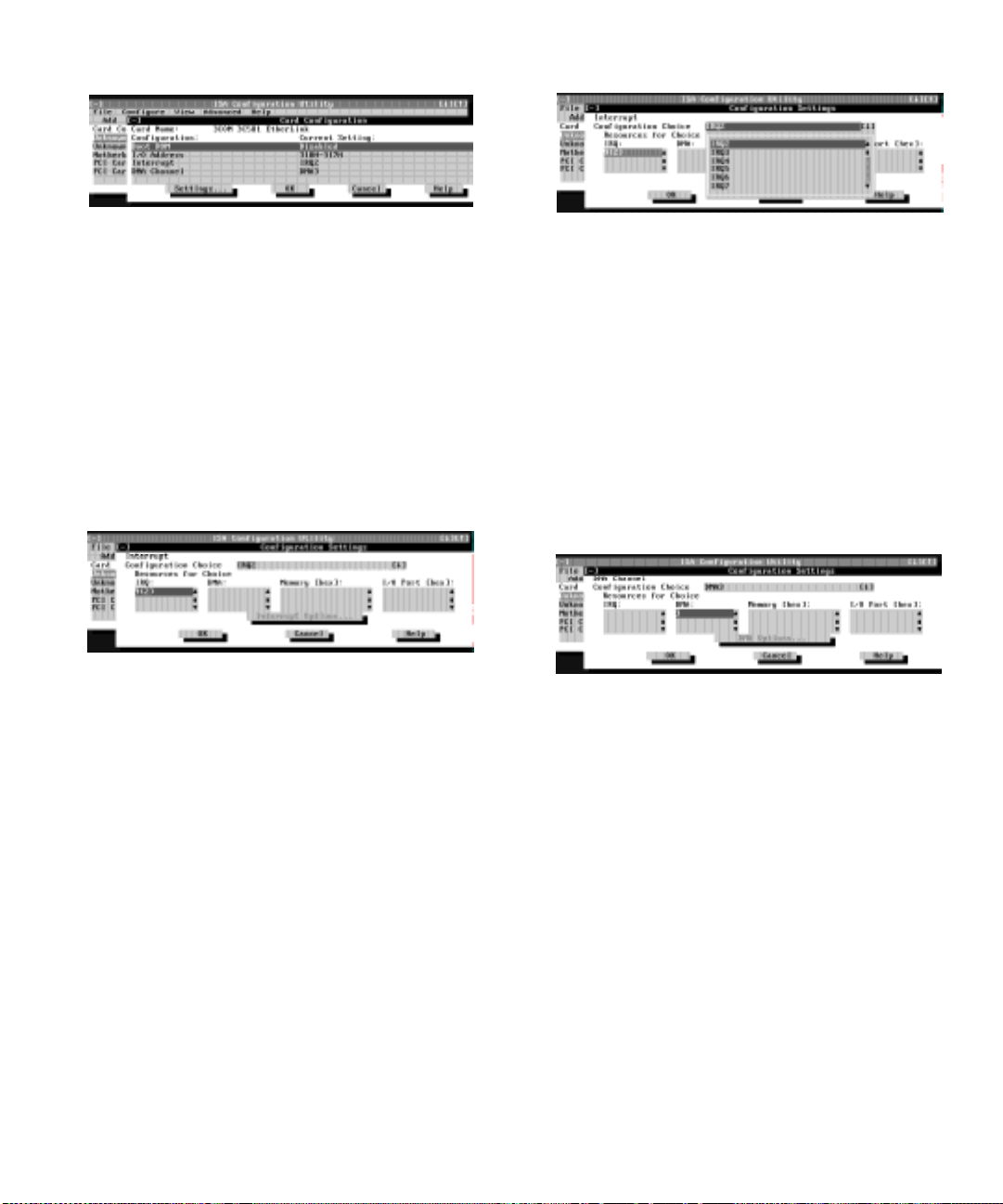
Figure 3-3. Card Configuration Dialog Box
Figure 3-5. Available Settings List Box
7. To change any of the resource settings for the
card, select the resource setting and then click
Settings.
The Configuration Settings dialog box (see Fig-
ure 3-4) displays the name of the resource that you
selected in the upper-left corner of the box. The
resource values currently associated with the
selected function are displayed in the Resources for
Choice box. The resource values displayed are IRQ,
DMA, Memory (Hex), and I/O Port (Hex).
Figure 3-4. Configuration Settings Dialog
Box for Assigning an IRQ Line
8. To change the resource settings, click the down
arrow next to the Configuration Choice box.
Then click the new resource setting from the list
of available settings (see Figure 3-5).
You cannot manually enter a value ; you must ch oose
a setting from the list. If there is only one setting
listed, no other settings are available.
The setting that you select may affect the resources
available. For example, if you are offered the Disabled option and select it, all resource values are
blank, indicating that a disabled set ti ng us es no
resources.
9. To change individual resource values for the current configuration setting, select the resource
value that you want to change an d click the
Options button located below the resource values
(see Figure 3-6).
For example, when you click the value under DMA,
the Options button changes to the DMA Options button. When you click this button, a smaller dialog box
appears. By clicking the down arrow next to the current resource value, you can display a list of the
available values for the resource.
Figure 3-6. Configuration Settings Dialog
Box for Assigning a DMA Channel
Choose the desired value and click OK. The value
you selected is displayed under the resour ce heading
in the Configuration Settings dialog box.
The Options button is disabled if no alternative
values are available for the selected resource.
NOTE: If you change one or more resource values
using the Options button and later change the setting
in the Configuration Choice box, the changes that
you made to the resource values are overwritten by
the default values for the new confi gu ration choice.
Using the ISA Configur ation Utility 3-5
Page 48

10. Click OK in the Configuration Settings dialog
box when you have finished selecting resources
for the function.
NOTE: After modifying the system configuration, you
must turn off the system to install, remove, or change
jumper settings on the non-Plug and Play ISA expansion
cards to match the settings you selected in the ICU.
A
dding an Unlisted Card
Unlisted cards are non-Plug and Play ISA expansion
cards that do not have configuration files stored in the
ICU databa se.
NOTE: If you want to add a configuration file that you
received on diskette with a new expansion card, see
“Adding a Listed Card” found earlier in this chapter.
T o add an unlisted card with the I CU, perform the f ollowing steps:
1. Start the ICU as described in “Starting the ICU”
found earlier in this chapter.
2. From the ICU window, click Add or select Add
Card from the Configure menu.
3. Click the name of the category of card that you
want to add. If you clicked Add in step 2, click
OK.
A dialog box appears listing the names of all available cards of that type.
4. Select Unlisted Card from the bottom of the list of
cards displayed in the dialog box that appears.
Then click OK.
5. Click No when the ICU asks if you have a configuration file for the card.
The Configure Unlisted Card dialog box appears
with blank fields .
6. Enter the name of the card that you want to add
in the Card Name field.
7. For each resource you want to assign to the card,
click the box beneath the name of the resource to
be assigned and then click Add.
For example, if you click the box beneath IRQ, the
button changes to Add Interrupt. When you click this
button, a Specify dialog box (in this case, Specify
Interrupt) appears. Figure 3-7 shows the Configure
Unlisted Card dialog box with the Specify Interrupt
dialog box opened.
Figure 3-7. Specify Interrupt Dialog Box
If you are providing a value for the interrupt request
(IRQ) or direct memory access (DMA) resource,
click the down arrow beneath Available Resources.
A smaller Specify list box appears (see Figure 3-8).
Click the value you want to assign to the resource.
Then click OK.
Figure 3-8. Specify Interrupt List Box
If none of the values for the DMA or IRQ resources
match the allowable values for your unlisted card (as
indicated in the card’s documentation), select one of
the available values offered by the utility and click
OK.
If you are providing values fo r the input/ output (I/ O)
port or memory resources, you must enter the starting and ending addresses in hexadecimal format
using the two fields provided by the Specify
Memory or Specify I/O Port dialog box. Click each
box in succession to enter the beginning and ending
addresses, and then click OK to complete the selection. Figure 3-9 shows the two fiel ds.
3-6 Dell OptiPlex GXa Mini Tower Systems Reference and Installation Guide
Page 49

Figure 3-9. Specify I/O Port Dialog Box
8. When you have finished selecting resources for
the unlisted card, click OK in the Configure
Unlisted Card dialog box.
A message box appears, notifying you either that the
card is using its default settings or that it cannot use
its default settings and must be reconfigured.
9. Click OK. If the card must be reconfigured,
record the resource settings recommended by the
ICU. Click Close to accept the resource settings
currently displayed.
10. If you had to assign a disallowed resource value to
the card in steps 7, 8, and 9, click each of the
other cards, and then click View until you find
another card using a resource value that is
allowed for the unlisted card. Reassign the
resource setting for this other card using the procedure in the next section, “Modifying a Card.”
Then modify the resource settings for the unlisted
card so that it uses an allowable value.
NOTE: After modifying the system configuration, you
must turn the system off to install, remove, or change
jumper settings on the non-Plug and Play ISA expansion
cards to match the settings you selected in the ICU.
M
odifying a Card
Modifying a card allows you to change the system
resources used by a card. This feature is helpful when
you want to add a card that requires resources already in
use by other cards or devices in your computer. You can
allocate different resources to the cards currently in your
computer to free the resources necessary for the card you
want to install.
You can also use this feature to force Plug and Play or
PCI expansion cards to use specific resource values. This
procedure is called locking a card. You should lock a card
only if it uses static device drivers. See “Locking and
Unlocking Cards” found later in this chapter for more
information.
NOTE: You cannot modify the resources of a Plug and
Play or PCI expansion card. You can only view the
resources currently assigned and lock or unlock them.
To modify the resource settings for a listed or unlisted
card, complete the following steps:
1. Start the ICU as described in “Starting the ICU”
found earlier in this chapter.
2. Select the card from the list of installed cards in
the ICU window, and choose Modify Card from
the Configure menu or click Modify.
If the Card Configuration dialog box appears, the
selected card is listed (it has a configuration file in
the ICU database). Continue with step 3.
If the Configure Unlisted Card dialog box appears,
the card is unlisted (it does not have a configuration
file). Proceed to step 5.
NOTE: When you modify an unlisted card, the ICU
cannot show you the valid resources for the card.
Therefore, you must have documentation from the
card manufacturer that describes the resources and
resource settings that the card can use.
3. Follow steps 7 through 9 in “Adding a Listed
Card” found earlier in this chapter. Then continue with step 4 of this procedure.
4. Click OK to complete the card modifications and
return to the ICU window.
You have completed this procedure; do not proceed
to step 5.
5. To add, modify , or r emo ve a re sour ce valu e, select
the box beneath the resource to be assigned, and
then click Add, Modify, or Remove, respectively.
For example, if you click the box beneath IRQ, the
Add, Modify, and Remove buttons change to Add
Interrupt, Modify Interrupt, and Remove Interrupt.
When you click one of these buttons, a smaller Specify list box (in this case, Specify Interrupt) appears.
Using the ISA Configur ation Utility 3-7
Page 50

If you are providing a value for the IRQ or DMA
resource, click the down arrow beneath Available
Resources. Click the value you want to assign to the
resource. If the resource can be shared with another
card or device, click Sharable. Then click OK.
If none of the values for the DMA or IRQ resource
match the allowable values for your unlisted card (as
indicated in the card’s documentation), select one of
the available values offered by the utility and click
OK.
If you are providing values for the I/O port or memory resource, you must enter the starting and ending
addresses in hexadecimal format using the two fields
provided by the Specify Mem ory o r Specify I/O Port
dialog box.
6. When you have finished selecting resources for
the unlisted card, click OK in the Configure
Unlisted Card dialog box.
A message box appears, notifying you either that the
card is using its default settings or that it cannot use
its default settings and must be reconfigured.
7. Click OK. If the card must be reconfigured,
record the resource settings recommended by the
ICU. Click Close to accept the resource settings
currently displayed.
8. If you had to assign a disallowed resource value to
the card in steps 5, 6, and 7, click each of the
other cards, and then click View until you find
another card using a resource value that is
allowed for the unlisted card. Reassign the
resource setting for this other card. Then modify
the resource settings for the unlisted card so that
it uses an allowable value.
NOTE: After modifying the system configuration, you
must turn off the system to install, remove, or change
jumper settings on the non-Plug and Play ISA expansion
cards to match the settings you selected in the ICU.
R
emoving a Card
Before you remove a non-Plug and Play ISA expansion
card from your computer, you must use the ICU to
remove the card from the system configuration.
NOTE: When you remove a Plug and Play or PCI expansion card from your computer, you d o no t need to run the
ICU. To remove a Plug and Play or PCI expansion card,
complete steps 2 through 9 in “Removing an Expansion
Card” in Chapter 6.
Use the following procedure to remove a non-Plug and
Play ISA expansion card from your computer:
1. Start the ICU as described in “Starting the ICU”
found earlier in this chapter.
2. Select the card from the current system configuration list in the ICU window.
3. Select Remove Card
menu, or click Remove.
The ICU requests verification that you want to
remove the card.
4. Click Yes to free the resources allocated to the
card and remove the card name from the list of
active cards, or click No to cancel the operation.
The ICU returns to the ICU window.
CAUTION: After removing a card from the
system configuration using the ICU, y ou must
turn off the system and physically remove the
card. Failure to do so can damage your system.
5. Remove the non-Plug and Play ISA expa nsion
card from the computer.
See “Removing an Expansion Card” in Chapter 6 for
instructions.
V
iewing Resources
The ICU displays all resources currently used by your
system.
To view all system resources, select System Resources
from the View menu or click View. The System Resource
Usage dialog box (see Figure 3-10) disp lays al l resources
currently used by the system.
from the Configuration
3-8 Dell OptiPlex GXa Mini Tower Systems Reference and Installation Guide
Page 51

Figure 3-10. System Resource Usage Dialog
Box
To determine which card uses a particular resource
shown in the System Resource Usage dialog box, select
the resource in question and then click Used By Card.
The Card Resource Usage dialog box appears with the
information.
To view the resources that a particular card is using,
select the card from the list displayed in the ICU window,
and then select Card Resources from the View menu or
click View. The Card Resource Usage dialog box displays the resources assigned to that card. Figure 3-11
shows resources that might be assigned to a network
adapter card.
Figure 3-11. Card Resource Usage Dialog Box
You can save the information displayed in the resource
usage dialog box by clicking Print To File. The ICU then
prompts you for a filename.
S
aving the System Configuration
You can save the system configuration to nonvolatile
random-access memory (NVRAM) as you configure
each card’s r esources. To do so, select Save from the File
menu and continue with your operation.
E
xiting From the ICU
At the ICU window, select Exit from the File menu to
exit the utility. If you have made any changes to the system configuration, you are asked whether you want to
save the changes.
If you click Yes, the ICU saves the updated system configuration information into NVRAM. If you click No,
you exit the ICU without saving any of your configuration changes. If you click Cancel, nothing is saved a nd
the utility continues to operate.
L
ocking and Unlocking Cards
The ICU includes a locking mechanism that enables you
to allocate the system resources for all or for some functions of Plug and Play and PCI expansion cards. These
expansion cards are dynamic, which means that they are
allocated resources at system start-up. Device drivers that
do not support this dynamic card configuration are
referred to as static device drivers.
T o det ermi n e whether you r expans ion card ha s stat i c
device drivers, check the documentation that came with
the drivers. If you are using a static device driver, you
need to permanently associate resources with a Plug and
Play expansion card, instead of relying on the default
Plug and Play behavior. Otherwise, the device driver
might not be able to find the card the next time the system boots. This procedure is referred to as locking a card.
NOTE: The locking feature of the ICU is valid only for
Plug and Play and PCI expansion cards.
Locking and Unlocking All Resources
T o lock or unlock all the resour ces and configur ations for
a Plug and Play or PCI expansion card, perform the following steps:
1. If it is not already installed, install the Plug and
Play or PCI expansion card. Then turn on the
system.
Complete steps 2 through 9 in “Installing an Expansion Card” in Chapter 6.
Using the ISA Configur ation Utility 3-9
Page 52

2. Start the ICU.
See “Starting the ICU” found earlier in this chapter.
3. Select Locking Enabled from the Advanced menu
in the ICU window .
A check mark next to Locking Enabled signifies that
the feature is active; a Lock button appears on the
tool bar.
4. Select the Plug and Play or PCI expansion card
that you want to lock or unlock from the Cards
Configured in System list.
5. Click Lock or select Lock/Unlock Card from the
Advanced menu.
Both options toggle the lock state of the selected
card.
Locking and Unlocking Configuration Resources
You can also lock and unlock individual resources for a
Plug and Play or PCI expansion card. To do so, perform
the following steps:
1. If it is not already installed, install the Plug and
Play or PCI expansion card. Then turn on the
system.
Complete steps 2 through 9 in “Installing an Expansion Card” in Chapter 6.
2. Start the ICU.
See “Starting the ICU” found earlier in this chapter.
3. Select Locking Enabled from the Advanced menu
in the ICU window.
A check mark next to Locking Enabled
the feature is active; a Lock button appears on the
tool bar.
4. Select the Plug and Play or PCI expansion card
that you want to lock or unlock from the Cards
Configured in System list.
5. Click Modify or select Modify Card from the Configure menu.
6. From the Card Configuration dialog box, select
the function you want to lock or unlock.
7. Click Settings.
8. Modify the resource setting and/or resources
offered on the Configuration Settin gs dialog box,
if necessary.
See “Modifying a Card” found earlier in this chapter
for more information.
9. Select Lock Resources.
The Lock Resources box toggles the lock state of the
selected configuration setting.
10. Repeat steps 6 through 9 for any other configuration settings that you want to lock or unlock.
11. Click OK in the Card Configuration dialog box
when you have finished making your selections .
signifies that
3-10 Dell OptiPlex GXa Mini Tower Systems Reference and Installation Guide
Page 53

Chapter 4
Using Integrated Devices
his chapter describes the configuration software pro-
T
vided with your system for the following integrated
devices:
•
Video controller
•
Audio controller
•
Optional network interface controller (NIC)
See the corresponding section in this chapter for the
device you want to configure or reconfigure.
V
ideo Controller
Your system has an ATI 3D Rage Pro accelerated graphics port (AGP) video controller, which includes video
drivers for the following operating systems:
•
Microsoft Windows 3. 1x and Windows for
Workgroups
•
Microsoft Windows 95
•
Microsoft Windows NT Workstation and Server
The video drivers for your operat ing system have already
been installed on your hard-disk drive. For information
on reinstalling video drivers, see “Using Drivers and
Utilities” in your online System User’s Guide. For
instructions on changing to a different video driver, see
your operating system documentation.
•
Microsoft Windows 95
•
Microsoft Windows NT Workstation and Server
The audio drivers for your operating syst em have already
been installed on your hard-disk drive. For information
on reinstalling audio drivers, reconfiguring the audio
controller, or using the audio utilities provided with your
system, see “Using the Audio Controller” in your online
System User’s Guide.
N
etwork Interface Controller
The optional 10/100-megabit-per-second (Mbps) 3Com
PCI
3C916B media access controller (MAC) NIC provides all the functions of a separate 3Com 3C905
network expansion card and suppo rt s both th e 10BASET and 100BASE-TX Ethernet standards.
NOTE: OptiPlex GXa systems also offer an optional
Wakeup On LAN-capable network card. For instructions
on installing the optional Wakeup On LAN-capable network card, see the documentation that came with the
network card.
The NIC connector on the computer’s back panel has the
following indicators (see Figure 4-1):
•
A yellow activity indicator flashes when the system
is transmitting or receiving network data. (A high
volume of network traffic may make this indic ator
appear to be in a steady “on” state.)
A
udio Controller
Your system has a Crystal CS4 236 B audi o controller and
includes audio drivers for the following operating
systems:
•
Microsoft Windows 3. 1x and Windows for
Workgroups
Using Integrated Devices 4-1
Page 54

A green link integrity indicator lights up when there is a
k
good connection between the network and the NIC.
parallel port
connector
mouse
connector
When the green indicator is off, the computer is not
detecting a physical connection to the network.
link integrity
indicator
activity indicator
microphone jack
line-out jack
line-in jac
serial port 1
connector
keyboard
connector
Figure 4-1. I/O Ports and Connectors
USB
connectors
serial port 2
connector
Network Cable Requirements
Your computer’s NIC connector (an RJ45 connector
located on the back panel) is designed for attaching an
unshielded twisted pair (UTP) Ethernet cable. Press one
end of the UTP cable into the NIC connector until the
cable snaps securely into place.
Connect the other end of the cable to an RJ45 jack wall
plate or to an RJ45 port on a UTP concentrator or hub,
depending on your network configuration. Observe the
following cabling restrictions for 10BASE-T and
100BASE-TX networks.
CAUTION:
data lines must be in separate sheaths.
•
For 10BASE-T networks, use Category 3 or greater
wiring and connectors.
•
For 100BASE-TX networks, use Category 5 wiring
and connectors.
•
The maximum cable run length (from a workstation
to a concentrator) is 328 feet (ft) (100 meters [m]).
•
The maximum number of works tations (no t counting
concentrators) on a network is 1024.
•
For 10BASE-T networks, the maximum number of
daisy-chained concent rators on one network segment
is four.
To avoid line interference, voice and
video connector
optional integrated
NIC connector
Configuring the NIC
This subsection provides in structions for configuring the
computer’s integrated, 10/100-Mbps 3Com NIC under
the following operating systems:
•
Microsoft Windows NT 4.0
•
Microsoft Windows NT 3.5x
•
Microsoft Windows f or Workgroups
•
Microsoft Windows 95
•
MS-DOS
NOTE: The NIC drivers for systems running a Dellinstalled Windows NT 4.0 or Windows 95 operating
system are automatically detected and installed. Instructions for reinstalling the NIC driver for Windows NT and
Win dow s 95 Ser v ice Rele a se 1 an d Serv ice R elea se 2 are
included later in this subsection.
Windows NT 4.0 NIC
The Windows NT 4.0 operating system automatically
detects and installs the NIC driver. To reinstall the driver,
complete the following steps:
1. Use the Dell Program Diskette Maker (located in
the Dell Accessories folder) to make a diskette
copy of the NIC drivers installed on your harddisk drive.
4-2 Dell OptiPlex GXa Mini Tower Systems Reference and Installation Guide
Page 55

2. Connect the network cable to the back of your
computer.
See “Network Cable Requirements” found earlier in
this chapter for detailed instructions.
3. Verify that the NIC is enabled in the System
Setup program.
See Chapter 2, “Using the System Setup Program,”
for more information.
4. Start the Windows NT operating system, and log
in as user Administrator or as a user with Administrator privileges.
For information on administrative users and privileges, see your Windows NT documentation.
5. Double-click My Computer, double-click Control
Panel, and then double-click the Network icon.
NOTE: If you are installing networking on your system for the first time, the Windows NT operating
system displays a message asking if you want to
install networking. Click Yes, and refer to your Windows NT docum entation for instru ctions.
6. Click the Adapters tab in the Network Control
Panel, and then click Add to access the Select Network Adapter window.
7. Click Have Di sk. Insert the NIC driver diskette 3
into drive A, type a:\, and then click OK.
The Select OEM Option dialog box appears.
8. Select 3Com Fast EtherLink XL NIC (3C905) for
the 10/100-Mb p s N IC, and then click OK.
9. When the operating system has finished copying
files from the NIC driver diskette 3, click Close in
the Windows W elcome screen. Then click Close in
the Network window.
10. If you are prompted, enter information about
your specific network.
See your system administrator for information.
11. Click Yes in the Netw ork Settings Ch ange window to restart your system.
Windows NT 3.5x NIC
To connect your system to and configure it for use on an
Ethernet network, you must complete the following
steps:
1. Use the Program Diskette Maker (located in the
Dell Accessories program group) to make a diskette copy of the NIC drivers installed on your
hard-disk drive.
2. Connect the network cable to the back of your
computer.
See “Network Cable Requirements” found earlier in
this chapter for detailed instructions.
3. Verify that the NIC is enabled in the System
Setup program.
See Chapter 2, “Using the System Setup Program,”
for more information.
4. Start the Windows NT operating system, and log
in as user Administrator or as a user with Administrator privileges.
For information on administrative users and privileges, see your Windows NT documentation.
5. Double-click the Program Manager, double-click
the Main group, and then double-click the Control Panel icon.
6. From the Control Panel, double-click the Network icon.
The Network Settings window appears.
7. From the Installed Adapters group, select the
existing 3Com driver and click Remove.
8. Click Yes in the Network Settings d i alog box.
9. Click Add Adapter in the Network Settings window. Then scro ll to <Other> Requires Disk From
Manufacturer, and click Continue.
10. Insert the NIC driver diskette 1 into drive A, type
a:\, and then click OK.
The Select OEM Option dialog box appears.
11. Select 3Com Fast EtherLink XL NIC (3C905) for
the 10/100-Mbps NIC, and then click OK.
12. When prompted, remove the NIC driver
diskette 1 from the diskette drive and insert the
NIC driver diskette 2.
Using Integrated Devices 4-3
Page 56

13. Click Close in the Windows Welcome scr een, and
then click Close again in the Network window.
14. If you are prompted, enter information about
your specific network.
See your system administrator for information.
15. Click Yes in the Netw ork Settings Ch ange window to restart your system.
Windows for Workgroups NIC
To connect your system to and configure it for use on an
Ethernet network, you must complete the following
steps:
1. Use the Program Diskette Maker (located in the
Dell Accessories program group) to make a diskette copy of the NIC drivers installed on your
hard-disk drive.
2. Connect the network cable to the back of your
computer.
See “Network Cable Requirements” found earlier in
this chapter for detailed instructions.
3. Verify that the NIC is enabled in the System
Setup program.
See Chapter 2, “Using the System Setup Program,”
for more information.
4. Start the Windows for Workgroups operating
system.
5. In the Main program group, double-click the
Windows Setup icon.
6. Click Continue to access the Windows Setup
screen.
7. Select Change Network Settings f rom the Options
menu.
8. From the Network Setup window, click Networks.
Then click Install Microsoft Windows Network,
and click OK.
9. Click Drivers to access the Network Drivers dialog box.
10. Click Add Adapter to access the Add Network
Adapter dialog box.
11. Select Unlisted or Updated Network Adapter , and
click OK.
12. Insert the NIC driver diskette 1 into drive A, and
click OK.
13. In the Unlisted or Updated Network Ada pter
dialog box, select 3Com EtherLink XL/Fast
EtherLink XL Adapter (3C90x) and click OK.
14. In the Network Drivers dialog box, click Close.
15. In the Network Setup dialog box, enter the User
Name, Workgroup Name, and Computer Name,
and click OK.
16. Click Yes to All in the Windows Set up dialog box.
17. Click OK when a message is displa yed on the
screen stating that the system files are being
updated.
18. If the Install Driver dialog box appears and
prompts you for the el90x.386 driver, type
a:\wfw311 and click OK to load the Network
Driver Interface Specification (NDIS) 3 driver.
If the Install Driver dialog box appears and
prompts you for the el90x.dos driver , type
a:\ndis2\dos and click OK to load the NDIS 2
driver.
19. Click OK to have the operating system make
backup copies of the system files.
20. Remove the diskette from drive A, save changes
to any open files, and then click Restart
Computer .
Windows 95 NIC
The Windows 95 operating system automatically detects
and installs the NIC driver. The following subsections
provide instructions for reinstalling the NIC driver on
systems running a Dell-installed Windows 95, Windows 95 Service Release 1, or Windows 95 Service
Release 2 operating system. Instructions for reinstalling
the NIC driver on systems running a Windows 95 operating system not installed by Dell are also included.
T o det ermi n e whether you r operati ng syst em is Windows 95, Win dows 95 Se rvice R elease 1, or W in dows 95
Service Release 2, click the Start button, point to Settings, and click Control Panel. Double-click the System
icon to access the System Properties window, and click
the General tab. If your system vers i on is 4.0 0, then you r
operating system is Windows 95. If your system version
is 4.00.950 A, then your operati ng sy stem is Windows 95
4-4 Dell OptiPlex GXa Mini Tower Systems Reference and Installation Guide
Page 57

Service Release 1. If your system version is 4.00.950 B,
then your operating system is Windows 95 Service
Release 2. For Windows 95 operating systems not
installed by Dell, the system version is 4.00.
NOTE: The instructions in the follow ing two subsections
are for the Windows 95 32-bit NDIS 3.0 driver. See
“Using the NDIS 2.01 Driver With Windows 95” found
later in this chapter for information on using the 16-bit
NDIS 2.01 driver with Windows 95.
Dell-Installed Windows 95, Dell-Installed Windows 95 Service Release 1, or Windows 95
Operating Systems Not Installed by Dell
To reinstall the NIC driver in a system running Dellinstalled Windows 95, Dell-installed Windows 95
Service Release 1, or a Windows 95 operating system not
installed by Dell, perform the following steps:
1. Use the Program Diskette Maker (located in the
Dell Accessories folder) to make a diskette copy of
the NIC drivers installed on your hard-disk drive.
2. Verify that the integrated NIC is enabled and
connected to its network.
See Chapter 2, “Using the System Setup Program,”
for more information.
3. Start the Windows 95 operating system.
4. Click the Start button, point to Settings, and click
the Control Panel. Then double-click the System
icon.
5. In the System Properties window , click the Device
Manager tab. In the list of system devices, doubleclick Other Devices. Then select PCI Ethernet
Controller, and click Properties to access the PCI
Ethernet Controller window.
6. Select the Driver tab, and then click Change
Driver to access the Select Hardware Type dialog
box.
7. Select Network Adapter, and then click OK to
access the Select Device window.
8. Click Have Disk to access the Install From Disk
dialog box.
9. Insert the NIC driver diskette 2
into drive A,
and
click OK.
The system reads the files on diskette and then displays the Select Network Adapters window.
10. Select 3Com Fast EtherLink XL 10/100Mb
Ethernet Adapter , and click OK to access the PCI
Ethernet Controller Properties dialog box.
11. Click OK to access the Network dialog box. Enter
your computer name and workgroup/domain.
Then click Close.
12. Click OK in the In sert Disk dialog bo x.
13. When prompted for the location of additional
files, specify the c:\windows\options\cabs directory
on your hard-disk drive or the \win95 directory
on your CD-ROM drive. Then click OK to access
the System Properties dialog box, and click OK.
14. Remove the diskette from drive A. Click the Start
button, click Shutdown, and then click R e start
the Computer.
15. Click Yes when prompted to restart the system.
Dell-Installed Windows 95 Service Release 2
To reinstall the NIC driver in a system running Dellinstalled Windows 95 Service Release 2, perform the
following steps:
1. Use the Program Diskette Maker (located in the
Dell Accessories folder) to make a diskette copy of
the NIC drivers installed on your hard-disk drive.
2. Verify that the integrated NIC is enabled and
connected to its network.
See Chapter 2, “Using the System Setup Program,”
for more information.
3. Start the Windows 95 operati ng system.
4. Click the Start menu, point to Settin gs, and click
Control Panel. Then double-click the System
icon.
5. In the System Properties window , click the Device
Manager tab.
6. In the list of system devices, double-click Other
Devices. Then click PCI Ethernet Controller.
7. Click Properties to access the PCI Ethernet Controller window.
Using Integrated Devices 4-5
Page 58

8. Click the Driver tab, and then click Update
Driver.
The Update Device Driver Wizard starts.
9. Insert the NIC driver diskette 2 into drive A, and
select Yes (Recommended).
10. Click Next and then click Finish to access the
Insert Disk dialog box.
11. Click OK to access the Copying Files dialog box.
Type a:\ and click OK.
The Windows 95 operating system begins to copy
files to the system’s hard-disk drive.
12. Click OK in the Insert Disk dialog box to access
the Copying Files dialog box.
13. When you are prompted for the location of additional files, specify the c:\windows\options\cabs
directory on your hard-disk drive or the \win95
directory on your CD-ROM drive. Then click OK
to access the System Properties dialog box, and
click OK.
The Windows 95 operating system finishes copying
all of the files to the system’s hard-disk drive.
14. When the System Settings Change dialog box
appears, remove the diskette from drive A and
click Yes to restart the system.
15. When the system restarts, the Enter Network
Password dialog box appears. Enter the
username and password yo u want to use for network access.
See your Windows 95 documentation for information about userna mes and passwords.
Using the NDIS 2.01 Driver With Windows 95
To install the 16-bit NDIS 2.01 NIC driver in systems
running Dell-installed Windows 95, Dell-installed Windows 95 Service Release 1, Dell-installed Windows 95
Service Release 2, or a Windows 95 operating system not
installed by Dell, perform the following steps:
1. Install the Windows 95 NIC d river.
For instructions, see “Dell-Installed Windows 95,
Dell-Installed Windows 95 Service Release 1, or
Windows 95 Operating Systems Not Installed by
Dell” found earlier in this chapter.
2. Click the Start menu, point to Settin gs, and click
the Control Panel. Then double-click the Network
icon.
3. In the Network window, select 3Com Fast EtherLink XL 10/100Mb TX Ethernet Adapter, and
then click Properties.
4. Select Real Mode (16bit) NDIS driver, and click
OK to return to the Network window.
5. Click OK, and then click Yes to restart your
system.
MS-DOS NIC
To connect your system to and configure it for use on an
Ethernet network, you must complete the following
steps:
1. Use the Program Diskette Maker (located in the
Dell Accessories program group or folder) to
make a diskette copy of the NIC drivers installed
on your hard-disk drive.
2. Connect the network cable to the back of your
computer.
See “Network Cable Requirements” found earlier in
this chapter for detailed instructions.
3. Verify that the NIC is enabled in the System
Setup program.
See Chapter 2, “Using the System Setup Program,”
for more information.
4. Configure the NIC, and install the network drivers by running the 3Com Install program
(install.exe) located on the NIC driver diskette 1.
5. Run the Network Interface Test Group
(3c90xcfg.exe) located on the NIC driver
diskette 1.
4-6 Dell OptiPlex GXa Mini Tower Systems Reference and Installation Guide
Page 59

Chapter 5
Working Inside Your Computer
Y
our Dell computer system supports a variety of
internal options that expand system capabilities. This
chapter prepares you to install options inside the computer. It describes how to remove and re place the
computer cover and expansion-card cage, as well as
rotate the power supply away from the system board. It
also familiarizes you with the internal components you
may handle if you install Dell hardware optio ns.
B
efore You Begin
T o make workin g ins ide y our comp uter ea sier, make sure
you have adequate lighting and a clean work space. If
you temporarily disconnect cables or remove expansion
cards, note the posit ion of the co nnectors and slots so that
you can reassemble the system correctly.
You will use the informati on in this section every time
you install a hardware opti on ins ide y our comp uter. Read
this section carefully, because the information is not
repeated in detail elsewhere in this guide.
Safety First—For You and Your Computer
W orking i nside your com puter is safe— if you observe the
following precautions.
WARNING FOR YOUR PERSONAL SAFETY
AND PROTECTION OF YOUR EQUIPMENT
Before starting to work on your computer, perform
the following steps in the sequence indicated:
1. Turn off your computer and all peripherals.
2. Disconnect your computer and peripherals
from their alternating current (AC) power
sources. Also, disconnect any telephone or telecommunication lines from the computer. Doing
so reduces the potential for personal injury or
shock.
3. If you are disconnecting a peripheral from the
computer or are removing a component from
the system board, wait 5 seconds after turning
off the computer before disconnecting the
peripheral or removing the component to avoid
possible damage to the system board.
4. Touch an unpainted metal surface on the computer chassis, such as the power supp ly, before
touching anything inside your computer.
While you work, periodically touch an unpainted
metal surface on the computer chassis to dissipate
any static electricity that might harm internal components. Also avoid touching components or
contacts on a card and avoid touching pins on a
chip.
In addition, Dell recommends that you periodically
review the safety instructions at the front of this guide.
Working Inside Your Computer 5-1
Page 60

Unpacking Your Hardware Option
When you remove an option from its shipping carton,
you may find it wrapped in antistatic packing material
designed to protect it from electrostatic damage. Do not
remove the packing material until you are ready to install
the option.
CAUTION: See “Protecting Against Electrostatic
Discharge” in the safety instructions at the front of
this guide.
R
emoving the Computer Cover
Use the following procedure to remove the computer
cover:
1. Turn off your computer and peripherals, and
observe the Warning for Your Personal Safety
and Protection of Your Equipment described
earlier in this chapter. Al so observe the safety
instructions at the front of this guide.
2. If you have installed a padlock through the
padlock ring on the back panel (s ee
Figure 5-1), remove the padlock.
3. Remove the cover.
Facing the left side cover, press the release button
(located at the bottom-left corner of the front bezel)
and lift the bottom of the cover, allowing it to pivot
up toward you (see Figure 5-2).
Disengage the tabs that secure the cover to the top of
the chassis, and lift the cover away.
release button
Figure 5-2. Removing the Computer Cover
R
eplacing the Computer Cover
Use the following procedure to replace the computer
cover:
1. Check all cable connections, especially those that
might have come loose during your work. Fold
padlock
ring
Figure 5-1. Padlock Installed
5-2 Dell OptiPlex GXa Mini Tower Systems Reference and Installation Guide
cables out of the way so that they do not catch on
the computer cover. Make sure cables are not
routed over the drive cage—they will prevent the
cover from closing properly.
2. Check to see that no tools or extra parts (including screws) are left inside the computer’s chassis.
Page 61

3. Replace the cover.
Facing the left side of the computer, hold the cover at
a slight angle as shown in Figure 5-3, and then align
the top of the cover with the top of the chassis. Insert
the tabs on the cover into the recessed slots on the
computer chassis so that the tabs catch the hooks
inside the slots.
Pivot the cover down toward the bottom of the chassis and into position. Make sure the securing hooks
at the bottom of the cover click into place.
tab
top
power
back
supply
system
board
bottom
drive
cage
internal drive
bracket
expansioncard cage
Figure 5-4. Computer Orientation View
front
recessed
slot
Figure 5-3. Replacing the Computer Cover
4. If you are using a p adlock to secure your system,
reinstall the padlock.
I
nside Your Computer
Figure 5-4 shows a side view of your computer to help
you orient yourself when installing hardware options.
Unless otherwise specified, locations or directions relative to the computer are as shown.
Figure 5-5 shows your computer with its cover removed.
Refer to this illustration to locate interior features and
components discussed in this guide.
When you look inside your compu t er, note the direct cur-
rent (DC) power cables coming from the power supply.
These cables supply power to the system board; to
internal diskette drives, hard-disk drives, and tape drives;
and to certain expansion cards that connect to external
peripherals.
The flat ribbon cable in Figure 5-5 is typical of the
face cables
for internal drives. An interface cable
inter-
connects a drive to a connector on the system bo ard or on
an expansion card.
The system board—the large printed circuit board
mounted vertically inside the chassis—holds the computer’s control circuitry and other electronic comp onents.
Some hardware options are installed directly onto the
system board. The riser board at the bottom of the chassis
contains the expansion-card connectors.
During an installation procedure, yo u may be req uired to
change a
jumper or
jumper
switch
setting on the system board and/or a
setting on an expansion card or on a
drive. Jumpers and switches provide a convenient and
reversible way of reconf ig uri n g t he circui tr y on a p ri nte d
circuit board. For information on jumpers and switches,
see the following two subsections.
Working Inside Your Computer 5-3
Page 62

Jumpers
Jumpers are small blocks on a circuit
board with two or more pins
emerging from them.
Plastic plugs containing a wire fit
down over the pins. The wire connects
the pins and creates a circuit.
To change a jumper setting, pull the plug
off its pin(s) and carefully fit it down onto
the pin(s) indicated.
CAUTION: Make sure your system is turned off
before you change a jumper setting. Otherwise,
damage to your system or unpredictable results
may occur.
A jumper is referred to as open or unjumpered when the
plug is pushed down over only one pin or if there is no
plug at all. When the plug is pu sh ed down over two pins,
the jumper is referred to as jumpered. In some docu-
ments, the jumper setting may be shown in text as two
numbers, such as 1-2. The number 1 is printed on the circuit board so that you can identify each pin number based
on the location of pin 1.
Figure 5-6 shows the location and default settings of the
jumper blocks on your system board. See Table 5-1 for
the designations, default settings, and functions of your
system’s jumpers.
Switches
Switches control various circuits or functions in your
computer system. The switches you are most likely to
encounter are dual in-line package (DIP) switches, which
are normally packaged in groups of two or more switches
in a plastic case. Two co mmon types of DIP switches are
slide switches and rocker switches (see the following
illustration).
slide switches rocker switches
Each of these switches has two positions, or settings
(usually on and off). To change the setting of a slide
switch, use a small, pointed object such as a small screwdriver or a straightened paper clip to slide the switch to
the proper position. To change the setting of a rocker
switch, use the screwdriver or paper clip to press down
on the appropriate side of the switch. In either case, do
not use a pen, pencil, or other object that might leave a
residue on the switch.
5-4 Dell OptiPlex GXa Mini Tower Systems Reference and Installation Guide
Page 63

security cable slot
AC power receptacle
parallel port connector
serial port 1 connector
keyboard connector
power supply
external drive bays
internal drive cage
mouse connector
USB connectors
serial port 2 connector
video connector
optional integrated
NIC connector
microphone jack
line-out jack
line-in jack
padlock ring
Figure 5-5. Inside the Chassis
interface cable
expansion-card
cage
riser board
system board
Working Inside Your Computer 5-5
Page 64

jumpered
unjumpered
Figure 5-6. System Board Jumpers
5-6 Dell OptiPlex GXa Mini Tower Systems Reference and Installation Guide
Page 65

Table 5-1. System-Board Jumper Settings
)
Jumper Setting Description
RSVD2 Reserved (do not change).
(default)
300MHZ* Jumpered when the microprocessor’s internal speed is 300 MHz.
266MHZ
233MHZ
BIOS
*
*
(default)
Jumpered when the microprocessor’s internal speed is 266 MHz.
Jumpered when the microprocessor’s internal speed is 233 MHz.
Reserved (do not change).
PSWD
(default
Password features are enabled.
Password features are disabled.
* One set of the speed jumper pins must have a jumper pl ug installed; otherwis e, the system will operate at an undetermined
speed.
NOTE: For the full name of an abbreviation or acronym used in this table, see the Glossary in your online
jumpered
unjumpered
System User’s Guide
System Board and Riser Board Labels
Table 5-2 lists the labels for connectors and sockets on
your system board and riser board, and it gives a brief
description of their functions.
Table 5-2. System Board and Riser Board Connectors and Sockets
.
Connector or Socket Description
BATTERY Battery socket
CD_IN CD-ROM audio interface connector
DIMM_x DIMM socket
DSKT Diskette/tape drive interface connector
ENET NIC connector (optional)
FAN Microprocessor fan connector
* Connector ISA1 shares a single card-slot opening with PCI4, and ISA2 shares with PCI5. Only one connector at a time can be
used on a shared card-slot opening.
NOTE: For the full name of an abbreviation or acronym used in this table, see the Glossary in your online
Working Inside Your Computer 5-7
System User’s Guide
.
Page 66

Table 5-2. System Board and Riser Board Connectors and Sockets
Connector or Socket Description
HDLED Hard-disk drive LED connector (on riser board)
IDEn EIDE interface connector
*
ISAn
KYBD Keyboard connector
LINE-IN Audio line-in jack
LINE-OUT Audio line-out jack (amplified source)
MIC Microphone jack
MONITOR V ideo conn ector
MOUSE Mouse connector
P1 Wakeup On LAN power connector (on riser board)
PANEL Control panel connector
PARALLEL Parallel port connector; sometimes referred to as LPT1
ISA expansion-card connector (on riser board)
(continued)
*
PCIn
POWER_1 Main power input connector
POWER_2 3.3-V power input connector
RISER Riser board connector
SERIAL
SLOT1 Pentium II processor SEC cartridge connector
USB USB connectors
VIDEO_UPGRADE Video-memory upgrade socket
* Connector ISA1 shares a single card-slot opening with PCI4, and ISA2 shares with PCI5. Only one connector at a time can be
NOTE: For the full name of an abbreviation or acronym used in this table, see the Glossary in your online
R
n
used on a shared card-slot opening.
emoving and Replacing the
Expansion-Card Cage
Your Dell computer has a removable expansion-card
PCI expansion-card connector (on ri ser b o a r d )
Serial port connector
System User’s Guide
cage, which greatly simplifies many installation procedures by allowing you to remove the riser board and all
installed expansion cards in a single step.
.
5-8 Dell OptiPlex GXa Mini Tower Systems Reference and Installation Guide
Page 67

Removing the Expansion-Card Cage
Use the following procedure to remove the expansioncard cage:
1. Remove the computer cover as instructed in
“Removing the Computer Cover” found earlier
in this chapter.
2. Check any cables connected to expansion cards
through the back-panel openings. Disconnect any
cables that will not reach to where the cage must
be placed upon removal from the chassis.
3. Locate the securing lever (see Figure 5-7). Rotate
the lever toward the back of the computer until it
stops.
4. Slide the expansion-card cage out of the chassis.
5. Lift the expansion-card cage up and away from
the chassis.
Replacing the Expansion-Card Cage
Use the following procedure to replace the expansioncard cage:
1. With the securing lever in its extended position,
align the tabs on the left and right sides of the
expansion-card cage with the slots on the back
and bottom of the chassis (see Figure 5-7). Slide
the expansion-card cage into place.
2. Rotate the securing lever inward until it is flush
with the side of the chassis. Make sure the riser
board is fully seated in the RISER connector on
the system board.
3. Reconnect any cables you removed in step 2 of the
previous procedure, “Removing the ExpansionCard Cage.”
R
otating the Power Supply Away
From the System Board
tabs
Figure 5-7. Removing the ExpansionCard Cage
securing
lever
T o access some components o n the system board, you may
have to rotate the system power su pply out of the way. Use
the following procedure to rotate the power supply:
1. Remove the computer cover as instructed in
“Removing the Computer Cover” found earlier
in this chapter.
2. Disconnect the AC power cable from the AC
power receptacle on the back of the power supply
(see Figure 5-8).
Working Inside Your Computer 5-9
Page 68

l
AC power
receptacle
power supp
y
3. Free the power supply from the securing tab
labeled “RELEASE —>,” and rotate it upward
until it locks in its extended position.
AC power cable
securing tab
DC power
cables
Figure 5-8. Rotating the Power Supply
5-10 Dell OptiPlex GXa Mini Tower Systems Reference and Installation Guide
Page 69

Chapter 6
Installing System Board Options
his chapter describes how to install the following
T
options:
•
Industry-Standard Architecture (ISA) and Peripher al
Component In terconnect (PC I) expansion c ards
•
System memory
parallel/serial port 1
connectors (stacked)
(PARALLEL/SERIAL1)
keyboard/mouse
connectors (stacked)
(KYBD/MOUSE)
USB connectors (USB)
serial port 2 connector
(SERIAL2)
microprocessor fan
connector (FAN)
video connector
(MONITOR)
video-memory upgrade
socket (VIDEO_UPGRADE)
optional integrated
NIC connector (ENET)
microphone jack (MIC)
audio line-out jack (LINE-OUT)
SEC cartridge connector (SLOT1)
•
Video memory
•
Microprocessor
This chapter also includes instructions for replacing the
system battery, if necessary.
Use Figure 6-1 to locate the system board features.
DIMM sockets (3) (DIMM_A–DIMM_C)
battery socket (BATTERY)
main power input
connector (POWER_1)
3.3-V power input connector
(POWER_2)
diskette/tape drive
interface connector
(DSKT) (pin-1 corner)
control panel
connector (PANEL)
secondary EIDE interface
connector (IDE2) (pin-1 corner)
primary EIDE interface
connector (IDE1) (pin-1 corner)
system board jumpers
audio line-in jack (LINE-IN)
riser board connector (RISER)
Figure 6-1. Sys t e m B oar d F e a tur e s
CD-ROM audio interface
connector (CD_IN)
bottom of computer
Installing System Board Options 6-1
Page 70

E
xpansion Cards
Expansion cards are installed on the computer’s riser
board (see Figure 6-3). The riser board plugs into the
RISER connector on the system board (see Figure 6-1)
and is considered an extension of the system board.
The system accommodates up to seven expansion cards,
which can be a mix of 32-bit PCI expansion cards and
8- and 16-bit ISA expansion cards. (See Figure 6-2 for
examples of ISA and PCI expansion cards.)
•
Expansion-card connectors PCI1–PCI5 support
32-bit PCI expansion cards.
NOTE: Because connector PCI4 shares expansionslot space with connector ISA1, and PCI5 shares
with ISA2, only one card of either type can be
installed in each of the two shared slots.
LED
PCI5
PCI4
PCI3
ISA4
ISA3
ISA2
ISA1
P1
8-bit ISA expansion card
16-bit ISA expansion card
32-bit PCI expansion card
Figure 6-2. Expansion Cards
Expansion Slots
Nine expansion-card connectors resi de on the riser board
(see Figure 6-3). Because two expansion slots are shared,
a maximum of seven expansion cards can be in st al le d on
the riser board.
•
Expansion-card connectors ISA1–ISA4 support
8- or 16-bit ISA expansion cards.
PCI2
PCI1
HDLED
connector
Figure 6-3. Riser-Board Expansion-Card
Connectors
Installing an Expansion Card
Follow this general procedure to install an expansion card:
1. If you are installing a non- Plug and Play ISA
expansion card, enter the ISA Configuration Utility (ICU) and add the new expansion card to your
configura ti on .
See Chapter 3, “Using the ISA Configuration Utility,” for instructions.
NOTE: If you in stall a PCI or Plug and Play expansion card, your system automatically performs any
required configuration tasks during the boot routine.
2. Prepare the expansion card for installation, and
remove the computer cover according to the
instructions in “Removing the Computer Cover”
in Chapter 5.
CAUTION: See “Protecting Against Electrostatic Discharge” in the safety instructions at
the front of this guide.
See the documentation that came with the expansion
card for information on config uring the card , making
6-2 Dell OptiPlex GXa Mini Tower Systems Reference and Installation Guide
Page 71

internal connections, or otherwise customizing the
card for your system.
3. Remove the expansion-card cage as instructed in
“Removing the Expansion-Card Cage” in Chapter 5.
NOTE: Verify that the power L ED on th e ris er board
(see Figure 6-3) is off before removing the card cage
4. Unscrew and remove the metal filler bracket that
covers the card-slot opening for the expansion
slot you intend to use (see Figure 6-4).
Save the screw to use when installing the expansion
card later in this procedure.
expansion card
card-edge connector
riser board
filler bracket
Figure 6-4. Removing the Filler Bracket
5. Install the expansion card.
Insert the card-edge connector firmly into the
expansion-card connector on the riser board. Gently
rock the card into the connector until the card is fully
seated (see Figure 6-5).
expansioncard cage
expansion-card
connector
Figure 6-5. Installing an Expansion Card
6. When the card is firmly seated in the connector
and the card-mounting bracket is flush with the
brackets on either side of it, secure the bracket
with the screw you removed in step 4.
7. If you are instal ling an option al W ak eup On LAN
network card, attach the three-wire power cable
that came with the card to the P1 connector on
the riser board (see Figure 6-3) and to the network card.
8. Replace the expansion-card cage in the chassis as
instructed in “Replacing the Expansion-Card
Cage” in Chapter 5.
9. Connect any cables that should be attached to the
card.
See the documentation that came with the card for
information about its cable connections.
10. Replace the computer cover, reconnect your computer and peripherals to their power sources, and
turn them on.
Installing System Board Options 6-3
Page 72

Removing an Expansion Card
Follow this general procedure to remove an expansion
card:
1. If you are removing a non-Plug and Play ISA
expansion card, enter the ICU and remove the
expansion card from your configuration.
See Chapter 3, “Using the ISA Configuration Utility,” for instructions.
2. Remove the computer cover according to the
instructions in “Removing the Computer Cover”
in Chapter 5.
CAUTION: See “Protecting Against Electrostatic Discharge” in the safety instructions at
the front of this guide.
3. If necessary, disconnect any cables connected to
the card.
4. Remove the expansion-card cage as instructed in
“Removing the Expansion-Card Cage” in Chapter 5.
5. Unscrew the mounting bracket of the card you
want to remove.
6. Grasp the card by its outside corners, and ease it
out of its connector.
7. If you are removing the card permanently, install
a metal filler bracket over the empty card-slot
opening.
NOTE: Installing filler brackets over empty cardslot openings is necessary to maintain Federal Communications Commission (FCC) certification of the
system. The brackets also keep dust and dirt out of
your computer.
8. Replace the expansion-card cage in the chassis as
instructed in “Replacing the Expansion-Card
Cage” in Chapter 5.
9. Replace the computer cover, reconnect your computer and peripherals to their power sources, and
turn them on.
A
dding Memory
Memory can be increased to a maximum of 384 megabytes (MB) by installing combinations of 16-, 32-, 64-, or
128-MB dual in-line memory modules (DIMMs) in the
three DIMM sockets on the system board. Figure 6-6
shows the DIMMs and DIMM sockets.
Your system can support both error checking and
correction (ECC) and non-parity synchronous dynamic
random-access memory (SDRAM) DIMMs. However,
ECC support is available only if all DIMMs are ECC
DIMMs. ECC DIMMs enable your system to correct all
single-bit memory errors and detect multibit memory
errors.
DIMMs (3)
DIMM
sockets
6-4 Dell OptiPlex GXa Mini Tower Systems Reference and Installation Guide
Page 73

T able 6-1 lists sample memory configurations and shows
valid DIMM combinations and socket placement for each
configuration.
.
Table 6-1. Sample DIMM Configuration Options
Total
Desired
Memory
ABC
DIMM Socket
16 MB 16 MB
32 MB 16 MB 16 MB
32 MB 32 MB
48 MB 16 MB 16 MB 16 MB
48 MB 32 MB 16 MB
64 MB 64 MB
64 MB 32 MB 32 MB
80 MB 32 MB 32 MB 16 MB
80 MB 64 MB 16 MB
96 MB 32 MB 32 MB 32 MB
96 MB 64 MB 16 MB 16 MB
112 MB 64 MB 32 MB 16 MB
128 MB 64 MB 64 MB
128 MB 128 MB
144 MB 64 MB 64 MB 16 MB
144 MB 128 MB 16 MB
160 MB 128 MB 32 MB
192 MB 128 MB 64 MB
192 MB 128 MB 32 MB 32 MB
256 MB 128 MB 128 MB
320 MB 128 MB 128 MB 64 MB
384 MB 128 MB 128 MB 128 MB
Performing a Memory Upgrade
Follow this procedure to perform a memory upgrade:
1. Remove the computer cover according to the
instructions in “Removing the Computer Cover”
in Chapter 5.
CAUTION: See “Protecting Against Electrostatic Discharge” in the safety instructions at
the front of this guide.
2. Rotate the power supply out of the way according
to the instructions in “Rotating the Power Supply
Away From the System Board” in Chapter 5.
3. Determine the DIMM sockets into which you will
install DIMMs or replace existing DIMMs.
See Figure 6-1 and Table 6-1.
4. Install or replace DIMMs as necessary to reach
the desired memory total.
Follow the instructions in “Installing a DIMM” or
Removing a DIMM,” as appropriate, found late r in
this section.
5. Rotate the power supply back into the computer
chassis.
6. Replace the computer cover; reconnect your computer and peripherals to their power sources, and
turn them on.
After the system completes the power-on self-test
(POST) routine, the system runs a memory test that
displays the total memory of all installed DIMMs,
including those you just installed.
NOTE: If the memory total is incorrect, turn off your
computer and peripherals and disconnect them from
their power sources, r emove the computer cover, and
make sure that th e inst all ed DIMM s are seated properly in their sockets. Then repeat this step.
The system detects that the new memory does not
match the existing system confi gurati on i nformat i on,
which is stored in nonvolatile rando m-access memory
(NVRAM), and generates the following message:
The amount of system memory has
changed.
Strike the F1 key to continue, F2 to
run the setup utility
Installing System Board Options 6-5
Page 74

7. Press <F2> to enter the System Setup program,
and check the System Memory category in the
lower-right corner of Page 1.
The system should have already changed the value in
the System Memory category to reflect the newly
installed memory. Verify the new total.
NOTES: If the memory total is incorrect, turn off
your computer and peripherals and disconnect them
from their power sources, remove the computer
cover, and check the installed DIMMs to make sure
that they are seated properly in their sockets. Then
repeat steps 6 and 7.
The value of System Memory is given in kilobytes. To
convert kilobytes to megabytes, divide the kilobyte
total by 1024.
8. When the System Memory total is correct, press
the <Esc> key to exit the System Setup program.
9. Run the Dell Diagnostics to verify that the
DIMMs are operating properly.
See your Diagnostics and T r ou bleshootin g Guide for
information on running the Dell Diagnostics and
troubleshooting any probl ems that may occur.
Installing a DIMM
Use the following procedure to install a DIMM:
1. Locate the first empty socket in which you plan to
install a DIMM.
For optimum performance, DIMMs should be
installed in consecutive sockets beginning with
socket A.
2. Locate the plastic securing clips at each end of the
socket. Press the clips outward until they snap
open.
3. Orient the DIMM to the socket by aligning the
notches in the DIMM’s edge connector with the
crossbars in the socket.
4. Press the DIMM straight into the slot running
down the center of the socket (see Figure 6-7)
until the securing clips snap into place around the
ends of the DIMM.
securing
clips (2)
Figure 6-7. Installing a DIMM
Removing a DIMM
To remove a DIMM, press the securing clips outward
(see Figure 6-8) simultaneou sly until the DIMM
disengages from the socket (it should pop up slightly).
Figure 6-8. Removing a DIMM
A
dding Video Memory
You can upgrade video memory from 2 to 4 MB by
installing a video-memory upgrade module. Upgrading
the video memory increases video performance and
allows you to use video modes for application programs
that require high resolutions and many colors.
6-6 Dell OptiPlex GXa Mini Tower Systems Reference and Installation Guide
Page 75

To upgrade the video memory, perform the following
steps:
1. Remove the computer cover according to the
instructions in “Removing the Computer Cover”
in Chapter 5.
CAUTION: See “Protecting Against Electrostatic Discharge” in the safety instructions at
the front of this guide.
2. T o access the video-memory upgrade socket
(labeled “VIDEO_UPGRADE”) on the sys t e m
board, remove the expansion-card cage as
described in “Removing the Expansion-Card
Cage” in Chapter 5.
3. Orient the module as shown in Figure 6-9. Then
install it in the socket.
Vi deo memory mod ul es are keyed , or designed to fit
in the socket in only one direction. The socket on the
system board is notched so that the video memory
module can be firmly seated only one way.
Align the video memory module’s edge connector
with the slot in the center of the socket. Press the
video memory module’s edge connector firmly into
the socket. Pivot the module down until it clicks into
place.
If you do not hear a sharp click, you should remove
the module and reinstall it.
notch
video-memory
upgrade socket
video-memory
upgrade module
5. Replace the computer cover; reconnect your computer and peripherals to their power sources, and
turn them on.
As the system boots, it detects the presence of the
new video memory and automatically changes the
system configuration information in the System
Setup program.
6. Enter the System Setup program, and confirm
that the amount of video memory displayed in the
Video Memory category is 4 MB.
See Chapter 2, “Using the System Setup Program.”
If the video memory total is incorrect, turn off the
system, remove the computer cover, and reseat the
video-memory upgrade module in its socket.
7. Run the Video Test Group in the Dell Diagnostics
to test the new video memory.
See your
instructions on running the Dell Diagnos t ic s and
troubleshooting any problems that occur.
U
pgrading the Microprocessor
To take advantage of future options in speed and functionality, you can replace the microprocessor on your
system board with any Dell-supported microprocessor
upgrade. Call your Dell sales representative for information on available microprocessor upgrades.
The microprocessor upgrade kit includes a new singleedge contact (SEC) cartridge with heat sink assembly and
an airflow shroud.
The following procedure describes how to replace the
microprocessor.
NOTE: Dell recommends that only a technically knowledgeable person perform this procedure.
1. Remove the computer cover according to the
instructions in “Removing the Computer Cover”
in Chapter 5.
Diagnostics and Tr oubleshooting Guide
for
Figure 6-9. Installing a Video-Memory
Upgrade Module
4. Replace the expansion-card cage as described in
“Replacing the Expansion-Card Cage” in Chapter 5.
CAUTION: See “Protecting Against Electrostatic Discharge” in the safety instructions at
the front of this guide.
Installing System Board Options 6-7
Page 76

2. Rotate the power supply out of the way according
to the instructions in “Rotating the Power Supply
Away From the System Board” in Chapter 5.
3. See Figure 6-1 to locate the SEC cartridge connector (labeled “SLOT1”) on the system board.
4. Press in on the heat sink clips that secure the cartridge/heat sink assembly to the meta l standoffs
on the system board (see Figure 6-10).
5. Remove the current SEC cartridge/heat sink
assembly from its connector.
Press the SEC cartridge release latches inward until
they snap into position. Grasp the SEC cartridge
firmly, and pull straight up on the cartridge to
remove it from the guide bracket assembly. You
must use up to 15 pounds of force to disengage the
SEC cartridge from the connector.
CAUTION: Make sure that the SEC cartridge
is only pulle d straight up to prevent da mage to
the processor or connector.
tabs (2)
heat sink
SEC cartridge
release latches (2)
SEC cartridge
guide bracket assembly
shroud
alignment slots (2)
cooling fan
securing clips (2)
Figure 6-10. Removing the Shroud and SEC Cartridge/Heat Sink Assembly
6-8 Dell OptiPlex GXa Mini Tower Systems Reference and Installation Guide
Page 77

6. Insert the new SEC cartridge/heat sink assembly
into the system board connector.
Press the SEC cartridge release latches outward until
they snap into position. Orient the assembly with the
heat sink facing toward the right (as you face the
front of the chassis), and press the SEC cartridge
firmly into its connector until it is fully seated. You
must use up to 25 pounds of force to fully seat the
SEC cartridge/heat sink assembly in the connector.
7. Slide the heat sink clips back into position.
8. If your upgrade kit included an airflow shroud,
install it over the SEC cartridge/heat sink
assembly.
Fit the mouth of the shrou d into the ali gnment slots on
the sides of the cooling fan. Then squeeze the tabs on
the top of the shroud and lower it down until the clips
under the tabs engage onto the top of the heat s i nk.
9. If necessary, change the microprocessor speed
jumper setting (see Figur e 5-6 to locate the system
board jumpers).
The microprocessor speed jumper should be set for
the installed microprocessor’s rated internal speed.
For example, for a 300-megahertz (MHz) Intel Pentium II processor, a jumper plug should be installed
on the pins labeled “300MHZ.” (See Table 5-1 for
more information.)
10. Rotate the power supply back into position.
11. Replace the computer cover; reconnect your computer and peripherals to their power sources, and
turn them on.
As the system boots, it detects the presence of the
new microprocessor and automatically changes the
system configuration information in the System
Setup program.
12. Enter the System Setup program, and confirm
that the Microprocessor category correctly identifies the installed microprocessor.
See Chapter 2, “Using the System Setup Program.”
13. Run the Dell Diagnostics to verify that the new
microprocessor is operating correctly.
See your Diagnostics and T r oubl eshooting Gu ide for
information on running the Dell Diagnostics and
troubleshooting any probl ems that may occur.
R
eplacing the System Battery
A 3.0-volt (V) CR2032 coin-cell battery installed on the
system board maintains system configuration, date, and
time information in a special section of memory.
The operating life of the battery can extend up to ten
years. The battery may need replacing if an inco rrect time
or date is displayed during the boot routine along with a
message such as:
Time-of-day not set — please run SETUP
program
or
Invalid configuration information —
please run SETUP program
or
Strike the F1 key to continue,
F2 to run the setup utility
T o determine whether the battery needs replacing, reenter
the time and date through the Sys tem Setup p rogram ( not
through the MS-DOS
the program properly to save the information (see
Chapter 2, “Using the System Setup Program,” for
instructions). T urn o ff your system and disco nnect it from
alternating current (AC) power for a few hours; then
reconnect and turn on your system. Enter the System
Setup program. If the date and time are not correct in the
System Setup program, replace your battery.
You can operate your system without a battery; however,
without a battery, the system configuration information is
erased if the system is turned off or unplugged from AC
power. In this case, you must enter the System Setup pro gram and reset the configuration options.
WARNING: There is a danger of the new battery
exploding if it is incorrectly installed. Replace the
battery only with the same or equivalent type recommended by the manufacturer. Discard used
batteries according to the manufacturer’s
instructions.
time
and
date
commands) and exit
Installing System Board Options 6-9
Page 78

Use the following procedure to replace the system battery
with another CR2032 coin-cell battery:
1. If you have not already done so, make a copy of
your system configuration information in the System Setup program.
If the settings are lost while you are replacing the
battery, refer to your written or printed copy of the
system configuration information to restore the correct settings. See Chapter 2, “Using the System
Setup Program,” for instructions.
2. Remove the computer cover according to the
instructions in “Removing the Computer Cover”
in Chapter 5.
CAUTION: See “Protecting Against Electrostatic Discharge” in the safety instructions at
the front of this guide.
3. To access the battery on the system board,
remove the expansion-card cage as described in
“Removing the Expansion-Card Cage” in Chapter 5.
4. Locate the battery and remove it.
The battery (see Figure 6-1) is mounted in a socket
labeled “BATTERY” in the front-right corner of the
system board (as you face the side of the system).
CAUTION: If you pry the battery out of its
socket with a blunt object, be careful not to
touch the system board with the object. Make
certain that the object is inserted between the
battery and the socket before attempting to
pry out the battery. Otherwise, you may damage the system board by prying off the socket
or by breaking circuit traces on the system
board.
Pry the battery out of its socket with your fingers or
with a blunt, nonconductive object, such as a plastic
screwdriver.
5. Install the new battery.
Orient the battery with the side labeled “+” facing up
(see Figure 6-11). Then insert the battery into the
socket, and snap it into place.
battery
BATTERY
socket
Figure 6-11. System Battery and Battery
Socket
6. Replace the expansion-card cage as described in
“Replacing the Expansion-Card Ca ge” in Chapter 5.
7. Replace the computer cover; reconnect your computer and peripherals to their power sources, and
turn them on.
8. Enter the System Setup program, and confirm
that the battery is operating properly.
See Chapter 2, “Using the System Setup Program,”
for information on running the System Setup
program.
Enter the correct time and date through the System
Setup program’ s T ime and Date categories. Al so, use
the copy you made in step 1 to restor e the correct settings for other system configuration information.
Then exit the System Setup program.
9. T urn off your computer, and unplug it for at least
ten minutes.
10. After ten minutes, plug in the computer, turn it
on, and enter the System Setup program. If the
time and date are still incorrect, see the chapter
titled “Getting Help” in your Diagnostics and
Troubleshooting Guide for instructions on obtaining technical assistance.
6-10 Dell OptiPlex GXa Mini Tower Systems Reference and Installation Guide
Page 79
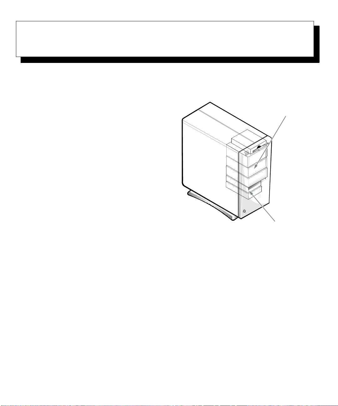
Chapter 7
)
Installing Drives
Y
our Dell computer has six drive bays for installing the
following types of drives (see Figure 7-1):
•
The externally accessible drive bays at the front of
the computer consist of one 3.5-inch dr ive bay (d edicated to a 3.5-inch diskette drive) and three
5.25-inch bays that can hold up to three half-height,
5.25-inch devices—typically tape drives or
CD-ROM drives. Alternately, 3.5-inch devices can
be installed in the 5.25-inch bays using adapters
available from Dell.
•
The two hard-disk drive bays can each hold a
3.5-inch enhanced integrated drive electronics
(EIDE) or small computer system interface (SCSI)
hard-disk drive . Together, the bays can hold one
1-inch-high (or smaller) drive and one 1.6-inch-high
(or smaller) drive.
The next three sections contain information that you will
need in several of the installation procedures described
later in the chapter. The remaining sections of this chapter cover each type of drive installation.
NOTE: In all of the following procedures,
refer to your left and right as you face the
computer.
left
front
and
of the
right
externally accessible
drive bays
two-bay hard-disk
drive area (internal
Figure 7-1. Drive Locations
R
emoving and Replacing the
Front Bezel
The bezel is secured to the front of the chassis by two
tabs and two hooks. The tab release for the bezel is at the
top of the computer chassis and can be accessed only
with the computer cover removed (see “Removing the
Computer Cover” in Chapter 5). With the cover removed,
release the bezel by pressing the tab release marked with
the icon (see Figure 7-2).
Installing Drives 7-1
Page 80

tab release
retaining hooks (2)
Figure 7-2. Removing the Front Bezel
While pressing the tab release, tilt the bezel away from
the chassis, disengage the two retaining hooks at the
bottom of the bezel, and carefully pull the bezel away
from the chassis.
To replace the bezel, fit the two retaining hooks on the
bezel into their corresponding slots at the bottom of the
chassis. Then rotate the top of the bezel toward the chassis until the top tabs snap into their correspon ding slots
on the bezel.
To remove the insert covering a 5.25-inch bay, follow
these steps:
1. Turn off the system, including any attached
peripherals, and disconnect all the alternating
current (AC) power cables from their power
sources.
2. Remove the computer cover as instructed in
“Removing the Computer Cover” in Chapter 5.
3. Remove the front bezel using the instructions in
the previous section, “Removing and Replacing
the Front Bezel.”
4. With your thumbs, press in each end of the insert
until it snaps free of the bezel (see Figure 7-3).
computer
cover
posts (2)
ring-tabs (2)
Figure 7-3. Removing the Front-Panel Insert
for a 5.25-Inch Bay
R
emoving and Replacing
Front-Panel Inserts
Empty drive bays contain a front-panel insert to protect
the inside of the computer from dust particles and also to
ensure proper airflow within the computer. Before you
install a drive in an empty drive bay, you must first
remove the front-panel insert.
7-2 Dell OptiPlex GXa Mini Tower Systems Reference and Installation Guide
To replace a front-panel insert for a 5.25-inch bay, work
from inside the bezel. Insert the two ring-tabs (one on
each end of the insert) over the posts on the inside of the
bay opening, and firmly press both ends of the insert into
place (see Figure 7-3).
Page 81

C
onnecting Drives
When installing a drive, you connect two cables—
a direct current (DC) power cable and an interface
cable—to the back of the drive. Your drive’s power input
connector (to which you connect the DC power cable)
resembles the connector shown in Figure 7-4.
power input
connector
DC power cable
Figure 7-4. DC Power Cable Connector
interface connector. For the location of pin 1 on the
drive’s interface connector, see the documentation that
came with the drive.
When disconnecting an interface cable from the system
board, be sure to press in on the locking tabs on the cable
connector before disconnecting the cable. When attaching an interface cable to the system board, be sure that the
locking tabs snap into place, ensuring that the cable is
firmly attached to the connector on the system board.
Most interface connectors are keyed for correct insertion;
that is, a notch or a missing pin on one connector matches
a tab or a filled-in hole on the other connector (see Figure 7-5). Keying ensures that the pin-1 wire in the cable
(indicated by the colored strip along one edge of the
cable) goes to the pin-1 end of the connector.
The pin-1 end of a connector on a board or a card is usually indicated by a silk-screened “1” printed directly on
the board or card.
The drive’s interface connector is a card-edge connector
or a header connector, as shown in Figure 7-5.
card-edge
connector
on drive
colored strip
header
connector
on drive
Figure 7-5. Drive Interface Connectors
When attaching the interface cable to a drive, be sure to
match the colored strip on the cable to pin 1 of the drive’s
notch
interface
cables
colored st rip
CAUTION: When connecting an interface cable,
do not reverse the interface cable (do not place the
colored strip away from pin 1 of the connector).
Reversing the cable prevents the drive from
operating and could damage the controller, the
drive, or both.
I
nstalling a Drive in a 5.25-Inch
Drive Bay
The 5.25-inch drive bays can accommodate any of the
following types of half-height drives:
•
A diskette drive or tape drive that uses the diskette/
tape drive interface on the system board
•
A CD-ROM or tape drive that uses the secondary
EIDE interface on the system board
•
A CD-ROM or tape dr ive that uses its own controller
card
NOTE: For information on configuring, connecting, and
installing SCSI drives, see “Installing SCSI Devices”
found later in this chapter.
Installing Drives 7-3
Page 82

To install a drive in a 5.25-inch drive bay, follow these
steps:
1. Unpack the drive and prepare it for installation.
CAUTION: Ground yourself by touching an
unpainted metal surface on the back of the
computer.
Check the documentation that accompanied the drive
to verify that the drive is configured for your computer system. Change any settings necessary for your
configuration.
NOTE: If you are installing a non-EIDE tape drive,
check the documentation for the drive to determine
the jumper or switch settings used to design ate the
drive as drive address DS4 (not DS2 or DS3 as may
be indicated in the drive documentation). Unless the
drive is already set to drive 4, reconfigure its jumper
or switch setting (see “Jumpers” and “Switches” in
Chapter 5).
If you are installing an EIDE CD-ROM or EIDE t ape
drive, configure the drive for the Cable Select
setting.
2. Remove the computer cover as instructed in
“Removing the Computer Cover” in Chapter 5.
CAUTION: See “Protecting Against Electrostatic Discharge” in the safety instructions at
the front of this guide.
bracket tabs (2)
Figure 7-6. Removing a Drive
If a drive is already installed in the bay and you are
replacing it, be sure to disconnect the DC power
cable and interface cable from the back of the drive
before sliding th e bracket out of the bay. To remove
the old drive from the bracket, tu rn the drive/bracket
assembly upside down and u nscrew the four screws
that secure the drive to the bracket (see Figure 7-7).
5. Attach the bracket to the new drive.
Turn the drive upside down and locate the four screw
holes around its perimeter. Fit the bracket over the
drive, and then tilt the front of the drive up so that
the bracket drops down into place. To ensure proper
installation, all screw holes should be aligned and
the tabs on the front of the bracket should be flush
with the front of the drive (see Figure 7-7).
3. Remove the front bezel according to the instructions in “Removing and Replacing the Front
Bezel” found earlier in this chapter.
4. Remove the drive bracket fr om the b ay you wa nt
to use.
Squeeze the metal tabs that extend from each side of
the drive bracket toward each other, and pull the
bracket out of the bay (see Figure 7-6).
NOTE: For easier access inside the chassis, you may
want to rotate the power supply out of the way temporarily. To do so, see “Rotating the Power Supply
Away From the System Board” in Chapter 5.
7-4 Dell OptiPlex GXa Mini Tower Systems Reference and Installation Guide
Page 83

bracket tabs (2)
bracket
Figure 7-7. Attaching the Drive Bracket to
the New Drive
To further ensure proper positioning of the drive in
the chassis, insert and tighten all four screws
order in which the holes are numbered
in the
(the holes are
marked “1” through “4”).
6. Slide the new drive into the drive bay until it
snaps securely into place (see Figure 7-8).
Make sure that both bracket tabs snap into place in
the drive bay.
7. If you are instal ling a drive that has i ts own controller card, install the controller card in an
expansion slot.
See “Installing an Expansion Card” in Chapter 6.
8. Connect a DC power cable to the power input
connector on the back of the drive (see
Figure 7-9).
9. Connect the appropriate interface cable to the
interface connector on the back of the drive (see
Figure 7-9).
If your system came with an EIDE CD-ROM or tape
drive, use the spare connector on the existing interface cable. Otherwise, use the EIDE interface cable
provided in the drive kit.
5.25-inch drive
Figure 7-8. Inserting the New Drive Into the
Drive Bay
Installing Drives 7-5
Page 84

CAUTION: You must match the colored strip
on the cable with pin 1 on the drive’s interface
connector to avoid possible damage to your
system.
interface connector
power input connector
DC power cable
diskette/tape drive
interface cable
Figure 7-9. Attaching Diskette Drive or Tape
Drive Cables
10. For an EIDE tape drive or CD-ROM drive, connect the other end of the interface cable to the
interface connector labeled “IDE2” on the system
board.
For a diskette drive or non-EIDE tape drive, connect
the cable from the drive to the interface connector
labeled “DSKT” on the system board.
For a drive that comes with its own controller card,
connect the other end of the interface cable to the
controller card.
Check all cable connections. Fold cables out of the
way to provide airflow for the fan and cooling vents.
7-6 Dell OptiPlex GXa Mini Tower Systems Reference and Installation Guide
Page 85

11. If the 5.25-inc h dr i v e bay was previously empty,
remove the front-panel insert fr om the front bezel.
See “Removing and Replacing Front-Panel Inserts”
found earlier in this chapter.
12. Replace the front bezel according to the instructions in “Removing and Replacing the Front
Bezel” found earlier in this chapter.
13. Replace the computer cover, and reconnect your
computer and peripherals to their power sources
and turn them on.
14. Update your system configuration information.
For a diskette drive, enter the System Setup program
and update the appropriate Diskette Drive category
(A or B) on Page 1 of the System Setup screens to
reflect the size and capacity of your new diskette
drive. (For more information, see Chapter 2, “Using
the System Setup Program.”)
If you installed a non-EIDE tape drive as the second
drive, set the Diskette Drive B category to Not
Installed.
For EIDE CD-ROM and tape drives, set the appropriate Drive category (0 or 1) under Drives:
Secondary to Auto.
15. Verify that your system works correctly.
See your Diagnostics and Troubleshooting Guide for
information on running the Dell Diagnostics and
troubleshooting any probl ems that may occur. Use
the following guidelines to determine which test to
use:
•
If you installed a diskette drive, test it by running all of the subtests in the Diskette Drive(s)
Test Group of the Dell Diagnostics.
•
If you installed a CD-ROM drive, see the
documentation that came with the drive for
instructions on loa di ng d evi ce dr i vers and us in g
the drive. If it is an EIDE CD-ROM drive, test
it by running all of the subtests in the IDE
CD-ROM Drives Test Group of the Dell
Diagnostics.
•
If you installed a tape drive, first verify that your
diskette drive is still operating correctly by running all of the subtests in the Diskette Drive(s)
Test Group of the Dell Diagnostics. Then perform a tape backup and verificatio n test with the
drive as instructed in the tape-drive software
documentation that came with the tape drive.
NOTE: The tape drives sold by Dell come with their
own operating software and documentation. After
you install a tape drive, refer to the documentation
that came with the drive for instructions on installing
and using the tape drive software.
I
nstalling an EIDE Hard-Disk Drive
This section includes information o n in stalling, partitioning, and formatting EIDE hard-disk drives. For
instructions on installing, partitioning, and formatting
SCSI hard-disk drives, see “Installing SCSI Devices”
found later in this chapter.
Up to two EIDE drives (one of which must be 1-inch
high or less) can be installed in the hard-disk drive
bracket below the drive cage. The first EIDE drive is
installed in the 1-inch (lower) drive bay labeled “HD1”; a
second drive is installed in the 1.6-inch bay labeled
“HD2.”
EIDE Drive Addressing
All EIDE devices should be configured for the Cable
Select jumper position, which assigns master and slave
status to devices by their position on the interface cable.
When two EIDE devices are connected to a single EIDE
interface cable and are configured for the Cable Select
jumper position, the device attached to the last connector
on the interface cable is the master or boot device (drive
0) and the device attached to the middle connector on the
interface cable is the slave device (drive 1). Refer to the
drive documentation in your upgrade kit for information
on setting devices to the Cable Select jump er position.
NOTE: If you want to install a seco nd EIDE dr ive tha t is
a different type from the first drive but you do not have
the specifications for the first drive, do one of the
following:
•
If you purc hased the drive fr om Dell, you can contact
Dell for the necessary reconfiguration information.
(See the chapter titled “Getting Help” in the Diag-
nostics and Troubleshooting Guide for instructions
on obtaining technical assistance.)
Installing Drives 7-7
Page 86

•
If you did not purchase the drive from Dell, call the
drive manufacturer.
With the two EIDE interface connectors on the system
board, your system can support up to four EIDE devices.
EIDE hard-disk drives should be connected to the EIDE
interface connector labeled “IDE1.” (EIDE tape drives
and CD-ROM drives should be connected to the EIDE
interface connector labeled “IDE2.”)
Remove the screw securing the hard-disk drive
bracket to the drive cage in the chassis.
Grasp the bracket, and rotate it outward from the
chassis until the sliding tab clears the slide rail on the
drive cage (see Figure 7-10). Lift the bracket up
slightly to free its hinge tabs from the chassis slots .
.
Installing an EIDE Hard-Disk Drive in the Hard-Disk Drive Bracket
Install an EIDE hard-disk drive in the hard-disk drive
bracket as follows:
1. If you are replacing a hard-disk drive that contains data you want to keep, be sure to make a
backup of your files before you begin this
procedure.
2. Prepare the drive for installation.
CAUTION: Ground yourself by touching an
unpainted metal surface on the back of the
computer.
CAUTION: When you unpack the drive, do
not set it on a hard surface, which may damage
the drive. Instead, set the drive on a surface,
such as a foam pad, that will su fficiently cushion it.
Check the documentation that accompanied the drive
to verify that it is configured for your computer
system.
3. Remove the computer cover as instructed in
“Removing the Computer Cover” in Chapter 5.
CAUTION: See “Protecting Against Electrostatic Discharge” in the safety instructions at
the front of this guide.
4. Remove the drive bracket from the chassis.
If a hard-disk drive is already installed in the drive
bracket, disconnect the DC power cable and EIDE
cable from the drive.
drive-cage slide rail
chassis slots
hinge tabs
sliding tab
Figure 7-10. Removing the Hard-Disk Drive
Bracket
5. Slide the drive into the chosen bay of the bracket,
oriented so that the connectors on the back of the
drive will face the back of the chassis when the
bracket is reinstalled (see Figure 7-11).
6. Align the four screw holes of the drive and
bracket. Insert and tighten the screws that came
with your upgra de ki t .
If you are installing a drive in the 1.6-inch bay, use
the four screw holes in the side of the bracket (see
Figure 7-11). If you are installing a drive in the
1-inch bay, use the four screw holes in the bottom of
the bracket.
7-8 Dell OptiPlex GXa Mini Tower Systems Reference and Installation Guide
Page 87

screws (4)
sliding tab
8. Connect a DC power cable to the power input connector on the back of the drive (see Figure 7-13).
Check all connectors to be certain that they are properly cabled and firmly seated.
9. Connect one of the device connectors on the EIDE
cable to the 40-pin interface connector on the
back of the hard-disk drive (see Figure 7-13).
CAUTION: You must match the colored strip
on the EIDE cable with pin 1 on the drive’s
interface connector to avoid possible damage
to your system.
1.6-inch drive
drive bracket
Figure 7-11. Inserting a 1.6-Inch Hard-Disk
Drive in the Bracket
7. Reinstall the hard-disk drive bracket in the chassis (see Figure 7-12).
Insert the bracket’s hinge tabs into the chassis slots so
that the tabs hook over the slots. Then rotate the bracket
toward the drive cage, and fit the bracket’s sliding tab
on the drive-cage slide rail. Slide the bracket into place.
Reinstall the screw you removed in step 4.
drive-cage
slide rail
chassis slots
hinge tabs
power input
connector on drive
DC power cable
interface
EIDE cable
IDE1 connector
IDE2 connector
connector
Figure 7-13. Attaching Hard-Disk Drive
Cables
sliding tab
Figure 7-12. Inserting the Drive Bracket in
the Chassis
Installing Drives 7-9
Page 88

10. If it is not already connected, connect the other
end of the EIDE cable to the IDE1 connector on
the system board.
CAUTION: You must match the colored strip
on the EIDE cable with pin 1 on the IDE1 connector to avoid possible damag e to you r syst em.
To locate the IDE1 connector, see Figure 6-1.
11. Replace the computer cover . Then reco nnect your
computer and peripherals to their power sources,
and turn them on.
12. Insert a bootable diskette (such as the Dell Diag-
nostics Diskette) into drive A, and turn on the
computer system.
13. Enter the System Setup program, and update the
appropriate Drive category (0 or 1) under Drives:
Primary.
See “Drives: Primary and Secondary” in Chapter 2.
After you update the System Setup settings, reboot
the system.
14. Partition an d logically format your drive, as
described in the next subsection, before proceeding to the next step.
15. Test the hard-disk drive by running the HardDisk Drive(s) Test Group in the Dell Diagnostics.
See your Diagnostics and T r ou bleshootin g Guide for
information on running the Dell Diagnostics and
troubleshooting any probl ems that may occur.
16. Install your operating system on the hard-disk
drive.
Refer to the documentation that came with your
operating system.
Partitioning and Logically Formatting Your EIDE Hard-Disk Drive
EIDE hard-disk drives must be physically formatted, partitioned, and logically formatted be fore they can be used
to store data. Every hard-disk drive from Dell is physically formatted before it is sent to you.
NOTE: On systems with hard-disk drives larger than
2 gigabytes (GB), create a primary partition of 2 GB and
divide the remaining capacity into partitions of 2 GB or
less. For example, a system with a 2.5-GB hard-disk
drive would have a primary partition of 2 GB (drive C)
and a second partition of 500 megabytes (MB) (drive D).
Hard-disk drives must be partitioned this way becaus e
MS-DOS–based operating systems (in cluding
Windows NT when using a file allocation table [FAT]
16 file system) do not support drive partitions larger than
2GB.
To partition and logically format your hard-disk drive,
use the program(s) offered by your operating system.
For MS-DOS
perform these procedures. The
mands are described in the MS-DOS reference
documentation.
For OS/2
formatting in the documentation that came with the op e rating system.
CAUTION: If you format your hard-disk drive
under the OS/2 High Performance File System
(HPFS), you cannot reformat the drive for
MS-DOS without losing all HPFS data. See your
OS/2 documentation for details.
For Windows NT
logical formatting in the documentation that came with
the operating system.
CAUTION: If you format your hard-disk drive
under the Windows NT File System (NTFS), you
cannot reformat the drive for MS-DOS without losing all NTFS data. See your Windows NT
documentation for details.
For the UNIX
documentation.
I
nstalling SCSI Devices
To use SCSI devices in your Dell computer, you must
have a SCSI host adapter card, which comes with its own
SCSI cable. This cable can be used to attach a variety of
SCSI devices (hard-disk drives, tape drives, and so on).
The SCSI host adapter configures the devices attached to
it as one subsystem—not as independent devices.
, use the
, see the discussion on partitioning and logical
®
fdisk
, see the discus sion on partitioning and
operating system,
format
and
fdisk
and
refer to your UNIX
commands to
format
com-
7-10 Dell OptiPlex GXa Mini Tower Systems Reference and Installation Guide
Page 89

Although SCSI devices are installed essentially the same
way as other devices, their configuration requirements
are different.
SCSI Configuration Guidelines
For details on configuring your SCSI subsystem, refer to
the documentation that came with your SCSI devices
and/or your host adapter card. The following subsections
offer some general guidelines.
SCSI ID Numbers
Each device attached to a SCSI host adapter card, as well
as the card itself, must have a unique SCSI identification
(ID) number from 0 to 7. W hen SCSI devices are s hipped
from Dell, the default SCSI ID numbers are assigned as
follows:
•
A SCSI host adapter card is configured as SCSI ID
7.
•
A SCSI tape drive or digital audio tape (DAT) drive
is configured as SCSI ID 6.
•
A SCSI CD-ROM drive is configured as SCSI ID 5.
•
SCSI hard-disk drives are usually configured as
SCSI ID 0. (The drive used to boot your system
should always be configured as SCSI ID 0.)
NOTE: There is
assigned sequentially or that devices be attached to the
cable in order by ID nu mber.
no
requirement that SCSI ID numbers be
SCSI Cable and S C SI Termina tion
The type of cabling you receive with your SCSI device
depends on the type of device you are installing.
•
If you are installing an internal narrow SCSI device
(such as a CD-ROM drive or tape drive)
50-pin internal SCSI cable as shown in Figure 7-14.
One end of this cable attaches to the SCSI host
adapter. Th e th ree co nnecto rs on the other end of the
cable are used for attaching up to three narrow SCSI
devices installed in the externally accessible drive
bays.
, you have a
50-pin SCSI
cable (to device in
externally accessible
drive bay)
68-pin SCSI cable
(to hard-disk drive)
Figure 7-14. Internal SCSI Cable
•
If you are installing an internal wide SCSI device
(such as a wid e SCSI hard-disk drive)
68-pin internal SCSI cable as shown in Figure 7-14.
One end of this cable attaches to the SCSI host
adapter and the two connectors on the other end of
the cable are used for attaching up to two SCSI harddisk drives installed in the hard-disk drive bracket.
•
If you are installing an external SCSI device
have a shielded external cable that connects to the
external SCSI connector on the SCSI host adapter
card. You have a separate power cable to connect the
SCSI device to an AC power source.
Before installing SCSI devices in your computer, you
may need to configure the termination on your SCSI
device(s). Both types of internal SCSI cables contain terminators on the device end of the cables, so the devices
connected to these cables must have termination disabled. Extern al SCSI cables do no t have terminators, so
termination must be enabled on the SCSI device itself.
If you are installing only internal SCSI devices, verify that
termination is enabled on the SCSI host adapter and disabled for all other internal SCSI devices. If you are installing
both internal and external SCSI devices, verify that termina-
, you have a
, you
Installing Drives 7-11
Page 90

tion is enabled on the external SCSI device and disabled for
the SCSI host adapter and all internal SCSI devices.
CAUTION: Do not connect devices to all three connectors (internal narrow connector, internal wide
connector, and external connector) on a single SCSI
host adapter card. Such a configuration is a violation of the SCSI specification. You can safely
connect devices to any two of these three connectors on a single SCSI host adapter card.
General Procedure for Installing SCSI Devices
Configure and install one or more SCSI devices in your
computer as follows:
1. Determine which connector on the internal SCSI
cable you will attach to each SCSI device.
See “SCSI Configuration Guidelines” found earlier
in this section.
2. Unpack each SCSI device and prepare it for
installation.
CAUTION: Ground yourself by touching an
unpainted metal surface on the back of the
computer.
CAUTION: When you unpack the drive, do not
set it on a hard surface, which may damage the
drive. Instead, set the drive on a surface, such as
a foam pad, that will sufficiently cus hion it.
Configure the device for a SCSI ID number and, if
necessary, enable or disable termination. For instructions, see the documentation that came with the
SCSI device as well as “SCSI Configuration Guidelines” found earlier in this section.
3. If you are installing a SCSI host adapter card,
configure the adapter card.
For instructions on configuring the card, see the documentation that came with the adapter card as well
as “SCSI Configuration Guidelines” found earlier in
this section.
4. Install the SCSI devices as appropriate.
•
To install a SCSI hard-disk drive, complete
steps 3 through 7 of “Installing an EIDE HardDisk Drive in the Hard-Disk Drive Bracket”
found earlier in this chapter. Then continue with
step 5 of this procedure.
•
To install a SCSI tape drive, CD-ROM drive, or
DAT drive, complete steps 2 through 6 of
“Installing a Drive in a 5.25-Inch Drive Bay”
found earlier in this chapter. Then continue with
step 5 of this procedure.
•
To install an external SCSI tape drive, continue
with step 5 of this procedure.
5. If you are installing a SCSI host adapter card,
install it in an expansion slot now.
See “Installing an Expansion Card” in Chapter 6.
If a SCSI host adapter card is already installed,
remove, reconfigure, and reinstall the card at this
time. See the documentation that came with the
SCSI host adapter card as well as “Removing an
Expansion Card” and “Installing an Expansion
Card” in Chapter 6.
Connect the hard-disk drive access cable to the SCSI
host adapter card and to the HDLED connector on
the riser board (see Figure 6-3). This cable carries a
signal from the SCSI host adapter card to the harddisk drive access indicator on the computer’s front
panel whenever one of the SCSI hard-disk drives is
accessed.
6. Attach the SCSI cable to each SCSI device.
For additional instructions on connecting SCSI
devices, see “SCSI Cable and SCSI Termination”
found earlier in this section.
If you are installing an internal SCSI device, firmly
press the SCSI cable’s header connector onto the 50or 68-pin connector on the back of the device.
CAUTION: You must match the colored strip
on the cable with pin 1 on the drive’s interface
connector to avoid possible damage to your
system.
7-12 Dell OptiPlex GXa Mini Tower Systems Reference and Installation Guide
Page 91

The connectors on narrow SCSI cables are keyed for
proper positioning—a raised area on the outside of
the header connector fits into a notch on the device
connector. The connectors on wide SCSI cables are
shaped so that they can be attached one way only.
If you are in stalling an exte rnal SCSI de vice, co nnect
one end of the external SCSI cable to the SCSI bus
connector on the back of the device.
7. Attach the SCSI cable to the connector on the
SCSI host adapter card.
If you are installing an internal SCSI device
•
connect the colored edge on the internal SCSI
cable to the pin-1 end of the 50-pin connector
(for a narrow SCSI device) or the 68-pin connector (for a wide SCSI device) on the adapter
card, and then press the cable connector firmly
onto the adapter card connector.
CAUTION: You must match the colored
strip on the internal SCSI cable with pin 1
on the adapter card connector to avoid
possible damage to your system.
•
If you are installing an external SCSI device,
connect the other end of the external SCSI cable
to the external connector on the adapter card.
For additional instructions, see the documentation
that came with the adapter card.
8. Connect the SCSI device(s) to power.
•
If you are installing an internal SCSI device,
connect a DC power cable to the power input
connector on the SCSI device.
•
If you are inst alling an e xtern al SCSI device, connect the socket end of the power cable into the
AC power receptacle on the back of the SCSI
device. Connect the other end of the power cable
into a standard electrical wall outlet.
Check all other cable connections. Fold all internal
cables out of the way to provide airflow for the fan
or cooling vents.
9. If you installed an externally accessible device,
remove the front bezel and remove the frontpanel insert for the drive bay from the front
bezel. Then replace the front bezel.
For instructions, see “Removing and Replacing the
Front Bezel” and “Removing and Replacing FrontPanel Inserts” found earlier in this chapter.
10. Replace the computer cover . Then reco nnect your
computer and peripherals to their power sources,
and turn them on.
11. If necessary, enter the System Setup program to
update the system configuration in formation.
If you installed a SCSI hard-disk drive, set the Drive
category (0 or 1) under Drives: Primary to None. For
,
instructions, see Chapter 2, “Using the System Setup
Program.”
Tape drives attached to a SCSI host adapter card are
not part of the system configuration information.
12. If you installed a SCSI hard-disk dr ive, partition
and format the drive. Then install the operating
system.
For instructions, see the next subsection, “Partitioning and Formatting SCSI Hard-Disk Drives,” and
your operating system documentation.
13. Test the SCSI devices.
Test a SCSI hard-disk drive by running th e SCSI
Device(s) Test Group of the Dell Diagnostics. See
your Diagnostics and Troubleshooting Guide for
information on running the Dell Diagnostics and
troubleshooting any problems that may occur.
T o test a SCSI tape drive, refer to the documentation
for the tape drive software to perform a tape drive
backup and verification test.
Partitioning and Formatting SCSI Hard-Disk Drives
You may need to use different programs than those provided with the operating system to partition and format
SCSI hard-disk drives. Refer to the doc umentation that
came with your SCSI so ftware drivers for information on
installing the appropriate drivers and preparing your
SCSI hard-disk drive for use.
NOTE: On systems with hard-disk drives larger than
2 GB, create a primary partition of 2 GB and divide the
remaining capacity into partitions of 2 GB or less. For
example, a system with a 2.5-GB hard-disk drive would
have a primary partition of 2 GB (drive C) and a second
Installing Drives 7-13
Page 92

partition of 500 MB (drive D). Hard-disk drives must be
partitioned this way because MS-DOS–based operating
systems (including Windows NT when using a FAT16 file
s ys tem) do no t support dr ive p a r t i t i o n s l a rger t han 2 GB.
7-14 Dell OptiPlex GXa Mini Tower Systems Reference and Installation Guide
Page 93

Appendix A
y
y
y
gn p
pg
g
y
p
g
p
y
y
y
Technical Specifications
Table A-1. Technical Specifications
Microprocessor
Microprocessor type . . . . . . . . . . . . . . . . . . Intel Pentium II microprocessor that runs at
233 MHz internall
266 MHz internall
300 MHz internall
Desi
u
be set throu
Internal cache . . . . . . . . . . . . . . . . . . . . . . . 32-KB first-level (16-KB data cache; 16-KB
instruction cache)
rovides for future Dell-supported
rades. A slower compatibility speed can
/66 MHz externally, at
/66 MHz externally, or at
/66 MHz externally.
h the System Setup program.
L2 cache memor
Math co
System chip set . . . . . . . . . . . . . . . . . . . . . . Intel 82440LX PCI/AGP
Data bus width . . . . . . . . . . . . . . . . . . . . . . 64 bits
Address bus width. . . . . . . . . . . . . . . . . . . . 32 bits
DMA channels . . . . . . . . . . . . . . . . . . . . . . ei
Interru
S
S
NOTE: For the full name of an abbreviation or acronym used in this table, see the Glossary in the
online
rocessor . . . . . . . . . . . . . . . . . . . . internal to Pentium II microprocessor
t levels . . . . . . . . . . . . . . . . . . . . . . 15
stem BIOS chip. . . . . . . . . . . . . . . . . . . . 2 Mb
stem clock. . . . . . . . . . . . . . . . . . . . . . . . 66 MHz (matches external processor speed)
S
stem User’s Guide.
. . . . . . . . . . . . . . . . . . . . 512-KB pipelined burst, four-way set-
associative, write-back SRAM
System Information
ht
Technical Specifications A-1
Page 94

Table A-1. Technical Specifications
Expansion Bus
(continued)
Bus types . . . . . . . . . . . . . . . . . . . . . . . . . . . PCI and ISA
Bus speed . . . . . . . . . . . . . . . . . . . . . . . . . . PCI: 33 MHz
ISA: 8.33 MHz
PCI expansion-card connectors . . . . . . . . . five (two PCI connectors share card-slot
openings with ISA connectors)
expansion-card connectors. . . . . . . . . . four (two ISA connectors share card-slot
ISA
openings with PCI connectors)
ISA expansion-card connector size. . . . . . . 98 pins
ISA expansion-card connector data width (maximum)
16 bits
PCI expansion-card connector size. . . . . . . 120 pins
PCI expansion-card connector data width (maximum)
32 bits
Memory
Architecture . . . . . . . . . . . . . . . . . . . . . . . . 64-bit (non-parity) or 72-bit (ECC),
noninterleaved
DIMM sockets . . . . . . . . . . . . . . . . . . . . . . three
DIMM capacities . . . . . . . . . . . . . . . . . . . . 16-, 32-, 64-, and 128-MB SDRAM
Standard RAM . . . . . . . . . . . . . . . . . . . . . . 16 MB minimum
Maximum RAM . . . . . . . . . . . . . . . . . . . . . 384 MB
BIOS address . . . . . . . . . . . . . . . . . . . . . . . F0000h
Drives
Externally accessible bays . . . . . . . . . . . . . three 5.25-inch bays for diskette, tape, or
CD-ROM drives; one 3.5-inch bay for a dis-
kette drive
Internally accessible bays . . . . . . . . . . . . . . two 3.5-inch bays: one for a 1-inch-high
hard-disk drive and one for a 1.6-inch-high
hard-disk drive
NOTE: For the full name of an abbreviation or acronym used in this table, see the Glossary in the
online System User’s Guide.
A-2 Dell OptiPlex GXa Mini Tower Systems Reference and Installation Guide
Page 95

Table A-1. Technical Specifications
Ports
(continued)
Externally accessible:
Serial (DTE). . . . . . . . . . . . . . . . . . . . . two 9-pin connectors; 16550-compatible
Parallel. . . . . . . . . . . . . . . . . . . . . . . . . one 25-hole connector (bidirectional)
Video . . . . . . . . . . . . . . . . . . . . . . . . . . one 15-hole connector
Optional integrated NIC . . . . . . . . . . . RJ45 connector
PS/2-style keyboard. . . . . . . . . . . . . . . 6-pin mini-DIN
PS/2-compatible mouse. . . . . . . . . . . . 6-pin mini-DIN
USB . . . . . . . . . . . . . . . . . . . . . . . . . . . two USB-compliant connectors
Audio line in . . . . . . . . . . . . . . . . . . . . miniature audio jack
Audio line out (amplified source) . . . . miniature audio jack
Microphone . . . . . . . . . . . . . . . . . . . . . miniature audio jack
Internally accessible:
Primary EIDE hard-disk drive. . . . . . . 40-pin connector on PCI local bus
Secondary E IDE hard-disk drive. . . . . 40-pin connector on PCI local bus
Diskette drive. . . . . . . . . . . . . . . . . . . . 34-pin connector
Video
Video type. . . . . . . . . . . . . . . . . . . . . . . . . . ATI 3D Rage Pro AGP controller
Video memory. . . . . . . . . . . . . . . . . . . . . . . 2 MB standard (upgradable to 4 MB)
Maximum resolution. . . . . . . . . . . . . . . . . . 1600 x 1200 pixels, 256 colors
Key Combinations
<Ctrl><Alt><Del> . . . . . . . . . . . . . . . . . . . . . . restarts (reboots) the system
<Ctrl><Alt><Enter>. . . . . . . . . . . . . . . . . . . . . starts System Setup program (during POST
only)
<Ctrl><Alt><\> . . . . . . . . . . . . . . . . . . . . . . . . toggles microprocessor speeds on 101-key
keyboard (in MS-DOS real mode only)
<Ctrl><Alt><#>. . . . . . . . . . . . . . . . . . . . . . . . toggles microprocessor speeds on 102-key
keyboard (in MS-DOS real mode only)
NOTE: For the full name of an abbreviation or acronym used in this table, see the Glossary in the
System User’s Guide.
online
Technical Specifications A-3
Page 96

Table A-1. Technical Specifications
Controls and Indicators
(continued)
Reset control. . . . . . . . . . . . . . . . . . . . . . . . push button
Power control . . . . . . . . . . . . . . . . . . . . . . . push button
Power indicators . . . . . . . . . . . . . . . . . . . . . green LEDs (one on front panel, one on riser
board)
Hard-disk drive access indicator. . . . . . . . . green LED
Link integrity indicator
(on optional integrated NIC connector) . . .
green LED
Activity indicator
(on optional integrated NIC connector) . . .
yellow LED
Power
DC power supply:
Wattage . . . . . . . . . . . . . . . . . . . . . . . . 200 W
Heat dissipation . . . . . . . . . . . . . . . . . . 913 BTUs (fully loaded system without
monitor)
Voltage. . . . . . . . . . . . . . . . . . . . . . . . . 90 to 135 V at 60 Hz;
180 to 265 V at 50 Hz
Backup battery . . . . . . . . . . . . . . . . . . . . . . 3-V CR2032 coin cell
Physical
Height . . . . . . . . . . . . . . . . . . . . . . . . . . . . . 44.4 cm (17.5 inches)
Width. . . . . . . . . . . . . . . . . . . . . . . . . . . . . . 20.6 cm (8.1 inches)
Depth. . . . . . . . . . . . . . . . . . . . . . . . . . . . . . 43.7 cm (17.2 inches)
Weight . . . . . . . . . . . . . . . . . . . . . . . . . . . . 14.3 kg (33.0 lb) or more, depending on
options installed
NOTE: For the full name of an abbreviation or acronym used in this table, see the Glossary in the
online System User’s Guide.
A-4 Dell OptiPlex GXa Mini Tower Systems Reference and Installation Guide
Page 97

Table A-1. Technical Specifications
Environmental
(continued)
Temperature:
Operating . . . . . . . . . . . . . . . . . . . . . . . 10° to 35°C (50° to 95 °F)
Storage. . . . . . . . . . . . . . . . . . . . . . . . . –40° to 65°C (–40° to 149°F)
Relative humidity . . . . . . . . . . . . . . . . 8% to 80% (noncondensing)
Maximum vibration:
Operating . . . . . . . . . . . . . . . . . . . . . . . 0.25 G at 3 to 200 Hz at 1 octave/min
Storage. . . . . . . . . . . . . . . . . . . . . . . . . 0.5 G at 3 to 200 Hz at 1 octave/min
Maximum shock:
Operating . . . . . . . . . . . . . . . . . . . . . . . bottom half-sine pulse with a change in
velocity of 20 inches/sec (50.8 cm/sec)
Storage. . . . . . . . . . . . . . . . . . . . . . . . . 27-G faired square wave with a velocity
change of 200 inches/sec (508 cm/sec)
Altitude:
Operating . . . . . . . . . . . . . . . . . . . . . . . –16 to 3048 m (–50 to 10,000 ft)
Storage. . . . . . . . . . . . . . . . . . . . . . . . . –16 to 10,600 m (–50 to 35,000 ft)
NOTE: For the full name of an abbreviation or acronym used in this table, see the Glossary in the
online System User’s Guide.
Technical Specifications A-5
Page 98

A-6 Dell OptiPlex GXa Mini Tower Systems Reference and Installation Guide
Page 99

Appendix B
ISA Configuration Utility Messages
he ISA Configuration Utility (ICU) and its Configu-
T
ration Manager are capable of identifying problems and
alerting you to them. Both utilities can alert you to problems with card configuration as well as problems that
prevent proper operation of the utility. This appendix
describes each type of message and lists the possible
causes and actions you can take to resolve any problems
indicated by a message. See the following tables to locate
your message and identify any possible corrective
actions.
Table B-1. Configuration Utility Messages
Message Probable Cause Corrective Action
I
CU Error Messages
The ICU can display a variety of error messages while in
operation. These messages alert you to problems that prevent the ICU from running correctly, as well as informing
you of resource conflicts that prevent the configu ration of
various cards in your computer. If you receive a message
from the ICU, see Table B-1 for suggestions o n resolvin g
any problems indicated by the message.
Out of memory
Memory allocation
failed
Not enough memory to
run the ICU
Can’t open index file.
This file is required
for ICU to run.
No Configuration Manager.
NOTE: For the full name of an abbreviation or acronym used in this table, see the Glossary in the online System User’s Guide.
Either of these messages can
appear if the system runs out
of memory during your
operation.
This message appears when
you start the ICU if the system does not have enough
memory to run the utility.
The ICU cannot find the
index file for its database.
The device driver needed by
the ICU is corrupted or is
not correctly configured.
Disable any TSR programs or any unneeded
device drivers.
Make sure to switch to drive A before attempting
to start the utility.
Verify that the following device statement appears
in your config.sys file:
device=
ers\dos\dwcfgmg.sys
In this statement, drive and dir ector y represent the
drive and directory where the driver resides. The
default is
drive:\directory
c:\plugplay
\driv-
.
ISA Configuration Utility Messages B-1
Page 100

Table B-1. Configuration Utility Messages
Message Probable Cause Corrective Action
(continued)
At least one Plug and
Play card in your system is not configured
due to conflicts.
These are marked “config err” in the list
of configured cards.
Due to conflicts, the
ICU could only configure some Plug and Play
cards in your system.
Unconfigured cards are
marked “config err” in
the list of configured
cards.
This device is unconfigurable because
of a resource conflict
with card card_name.
The conflicting
resource is
resource_name. To fix,
reconfigure the conflicting card.
The Configuration Manager
or the ICU cannot configure
at least one Plug and Play
expansion card because of
resource conflicts with one
or more cards.
The selected card is unconfigurable because one of
its resources is already being
used by another device.
You must reconfigure the conflicting card(s). To
find the conflicting card, perform the following
steps:
1. Select the Plug and Play expansion card
marked with
config err
, and then click
the Modify button.
The Card Configuration dialog box displays
the functions assigned to the Plug and Play
expansion card.
2. Select a function and then click Sett ings.
Click Cancel if the ICU does not display a
message naming the conflicting card.
3. Repeat step 2 until the ICU displays a message box naming the conflicting card and
the resource(s) in conflict. See the following table entry for an explanation of this
message box.
Perform the following procedure:
1. Make a note of the card name and the type
of conflicting resource.
2. Follow the procedure in “Modifying a
Card” in Chapter 3, and change the value
for
resource_name
used by
card_name
.
The ICU has
successfully configured all Plug and Play
cards in your system.
For the new
The ICU has successfully
configured all of the Plug
and Play expansion cards
that were not configured by
the Configuration Manager.
To accept these settings, save the configuration
information into NVRAM by selecting Exit from
the File menu and then selecting Yes to save. You
must reboot your system for these settings to take
effect.
configuration to take
effect, save the configuration, then
reboot your system.
The loaded card is not
a category card. Press
OK to proceed.
The category you have
chosen is not the correct category under which to add
this card.
Select OK. The ICU automatically opens the
correct category’ s dialog box. Continue the procedure for adding the card as described in “Adding a
Listed Card” or “Adding an Unlisted Card” in
Chapter 3.
NOTE: For the full name of an abbreviation or acronym used in this table, see the Glossary in the online
B-2 Dell OptiPlex GXa Mini Tower Systems Reference and Installation Guide
System User’s Guide
.
 Loading...