

Page 1
Dell™ Latitude™ C600/C500 Series
SERVICE MANUAL
www.dell.com
support.dell.com
Page 2

Page 3

Dell™ Latitude™ C600/C500 Series
SERVICE MANUAL
www.dell.com
support.dell.com
Page 4

Notes, Notices, and Cautions
NOTE: A NOTE indicates important information that helps you make better
use of your computer.
NOTICE: A NOTICE indicates either potential damage to hardware or loss of
data and tells you how to avoid the problem.
CAUTION: A CAUTION indicates a potentially hazardous situation
which, if not avoided, may result in minor or moderate injury.
____________________
Information in this do cum e nt is subj ec t to change without notice.
© 2001 Dell Computer Corporation. All rights reserved.
Reproduction in any manner whatsoever without the written pe rmission of Dell Computer
Corporation is strictly forbidden.
Trademarks used in this text:
Corporation;
registered trademarks of Microsoft Corporation.
Other trademarks and trade names may be used in this document to refer to either the entities
claiming the marks and names or their products. Dell Computer Corporatio n discla ims any
proprietary interest in trad em arks and trade names other than its own.
May 2001
May 2001 P/N 82EWX
May 2001May 2001
Intel
is a registered trademark of Intel Corporation;
P/N 82EWX Rev. A01
P/N 82EWXP/N 82EWX
Dell
, the
DELL
Rev. A01
Rev. A01Rev. A01
logo, and
DellWare
are trademarks of Dell Computer
Microsoft
and
Windows
are
Page 5

Contents
1 Before You Begin
Preparing to Work Inside the Computer . . . . . . . . . . . . . . 10
Recommended Tools
. . . . . . . . . . . . . . . . . . . . . . . . 11
Screw Identification . . . . . . . . . . . . . . . . . . . . . . . . 12
2 Removing and Replacing Parts
Components . . . . . . . . . . . . . . . . . . . . . . . . . . . . 16
Hard Drive
Memory Module
Mini-PCI Card Assembly
Keyboard Assembly . . . . . . . . . . . . . . . . . . . . . . . . . 23
. . . . . . . . . . . . . . . . . . . . . . . . . . . . . 17
Removing the Hard Drive
Replacing the Hard Drive
. . . . . . . . . . . . . . . . . . . . . . . . . . 18
. . . . . . . . . . . . . . . . . . . . 17
. . . . . . . . . . . . . . . . . . . . 17
Removing the Memory Module Cover
Removing the Memory Modules
. . . . . . . . . . . . . . . . . 19
Rep lac in g the Memo ry Modules . . . . . . . . . . . . . . . . . 20
. . . . . . . . . . . . . . . . . . . . . . 20
Removing the Mini-PCI Card Assembly
Replacing the Mini-PCI Card Assembly . . . . . . . . . . . . . 22
Removing the Keyboard Assembly
Replacing the Keyboard Assembly . . . . . . . . . . . . . . . . 25
. . . . . . . . . . . . . . 18
. . . . . . . . . . . . . 22
. . . . . . . . . . . . . . . . 23
Removing the Display Assembly . . . . . . . . . . . . . . . . . . 26
Removing the 14.1-Inch Display Assembly Bezel
. . . . . . . . 30
Removing the 14.1-Inch Display Panel . . . . . . . . . . . . . 30
Contents 5
Page 6

Replacing the 14.1-Inch Display Panel . . . . . . . . . . . . . 31
Removing the Display-Feed Flex Cable (14.1-Inch Displa y Panel) 32
Removing the 12.1-Inch Display Assembly Bezel
. . . . . . . . 34
Removing the 12.1-Inch Display Panel . . . . . . . . . . . . . 34
Replacing the Display-Assembly Top Cover . . . . . . . . . . . 35
Replacing the 12.1-Inch Display Panel
. . . . . . . . . . . . . 35
Removing the Display-Feed Flex Cable (12.1-Inch Displa y Panel) 36
Display Assembly Latch . . . . . . . . . . . . . . . . . . . . . . 37
Removing the Display Assembly Latch
. . . . . . . . . . . . . . 37
Hinge Covers
Removing the Hinge Covers
Replacing the Hinge Covers
Palmrest Assembly
Removing the Palmrest Assembly
. . . . . . . . . . . . . . . . . . . . . . . . . . . . 39
. . . . . . . . . . . . . . . . . . . 39
. . . . . . . . . . . . . . . . . . . 40
. . . . . . . . . . . . . . . . . . . . . . . . . 41
. . . . . . . . . . . . . . . . 41
Microprocessor Thermal Cooling Assembly . . . . . . . . . . . . 44
Removing the Microprocessor Thermal Cooling Assembly
. . . . 44
Hybrid Cooling Fan . . . . . . . . . . . . . . . . . . . . . . . . . 45
Removing the Hybrid Cooling Fan
Microprocessor Module
. . . . . . . . . . . . . . . . . . . . . . . 47
Removing the Microprocessor Module
Replacing the Microprocessor Module
Reserve Battery
. . . . . . . . . . . . . . . . . . . . . . . . . . . 49
Removing the Reserve Battery
Replacing the Reserve Battery
Speaker Assemblies
. . . . . . . . . . . . . . . . . . . . . . . . . 50
Removing the Speaker Assemblies
Rep lac in g t he Spe ak er A sse m bl y
. . . . . . . . . . . . . . . . 46
. . . . . . . . . . . . . . 47
. . . . . . . . . . . . . . 48
. . . . . . . . . . . . . . . . . . 49
. . . . . . . . . . . . . . . . . . 50
. . . . . . . . . . . . . . . . 51
. . . . . . . . . . . . . . . . 53
System Board Assembly
Removing the System Board
Replacing the System Board
. . . . . . . . . . . . . . . . . . . . . . 53
. . . . . . . . . . . . . . . . . . . 54
. . . . . . . . . . . . . . . . . . . 56
Contents 6
Page 7

Battery and Modular Bay Latch Assemblies . . . . . . . . . . . . 57
Removing the Battery and Modular Bay Latch Assemblies
. . . . 57
Index . . . . . . . . . . . . . . . . . . . . . . . . . . . . . . . . . . . 59
Contents 7
Page 8

8 Contents
Page 9
SECTION 1
Before You Begin
Preparing to Work Inside the Comput er
Recommended Tools
Screw Identification
www.dell.com | support.dell.com
Page 10

Preparing to Work Inside the Computer
NOTICE: Only a certified service technician should perform repairs on your
system. Damage due to servicing that is not authorized by Dell is not covered
by your warranty.
NOTICE: To avoid damaging the computer , perform the following steps before
you begin working inside the computer.
1 Make sure that the work surface is clean to prevent scratching the
computer cover.
www.dell.com | support.dell.com
2 Save any work in progress and close all open application programs.
3 Turn off the computer and all attached devices.
NOTE: Make sure the computer is turned off and not in suspend-to-disk
or hibernate mode. If you cannot shut down the computer using the
computer’s operating system, press and hold the power button for
4seconds.
4 Make sure the computer is undocked.
5 Disconnect the computer from the electrical outlet.
6 To avoid pos sible damage to the system board, wait 10 to 20 seconds
and then disconnect any attached devices.
7 Disconnect all other external cables from the computer.
8 Remove any installed PC Cards or plastic bla nks from the PC Card
slot.
9 Close the display and turn the computer upside down on a flat work
surface.
NOTICE: To avoid damaging the system board, you must remove the main
battery and secondar y battery (if present) before you service the computer.
Remove the primary battery from the battery bay and the secondary
10
battery from the modular bay, if a secondary battery is in use.
11 Remove any installed device in the modular bay.
10 Before You Begin
12 To diss ipate any static elect ricity while you work, use a wrist grounding
strap or periodically touch an unpainted metal surface.
Page 11
13 Handle components and cards with care. Do not touch the
components or contacts on a card. Hold a card by it edges or by its
metal mounting bracket. Hold a component such as a microprocessor
by its edges, not by its pins.
Recommended Tools
The procedures in this manual require the following tools:
• #1 magnetized Phillips screwdriver
• Small flat-blade screwdriver
• Small plastic sc ribe
• Microprocessor extractor
• Flash BIOS update program diskette or CD (required only when
upgrading the microprocessor or replacing the reserve battery)
System Orientation
back
front
rightleft
Before You Begin 11
Page 12
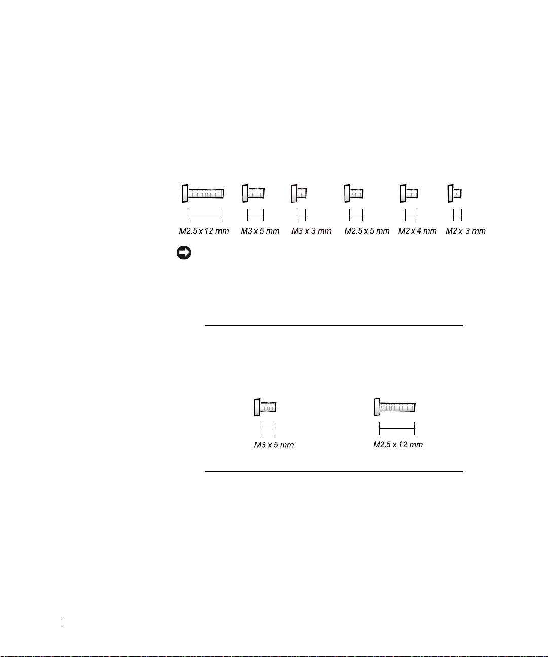
Screw Identification
When you are removing and replacing components, photocopy the
placemat as a tool to lay out and keep track of the component screws. The
placemat provides the number of screws and the sizes.
Screw Identificat ion
www.dell.com | support.dell.com
NOTICE: When reinstalling a screw, you must use a screw of the correct
diameter and length. Make sure that the screw is properly aligned with its
corresponding hole, and avoid overtightening.
Screw Placement
12 Before You Begin
Hard Drive
Door Security:
(1 each)
Keyboard to Bottom
Case Assembly:
(5 each)
Page 13
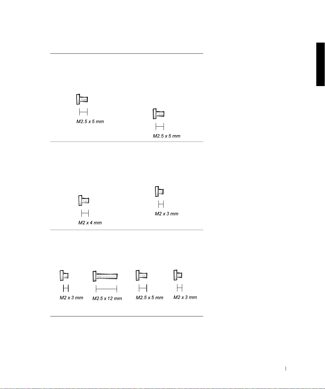
Screw Placement
Display Assembly
Bezel:
(6 each)
Rubber Screw Covers (6 each)
Display Assembly
and Flex Cable
Retention Bracket to
Top Cover:
(5 each)
Display Assembly
Hinge Bracket to
Bottom Case
Assembly:
(5 each)
Display Assembly
EMI Shield Bracket:
(2 each)
Palmrest to Bottom
Case Assembly:
(5 each) (3 each)
Hybrid Cooling Fan:
(2 each) (1 each)
Before You Begin 13
Page 14
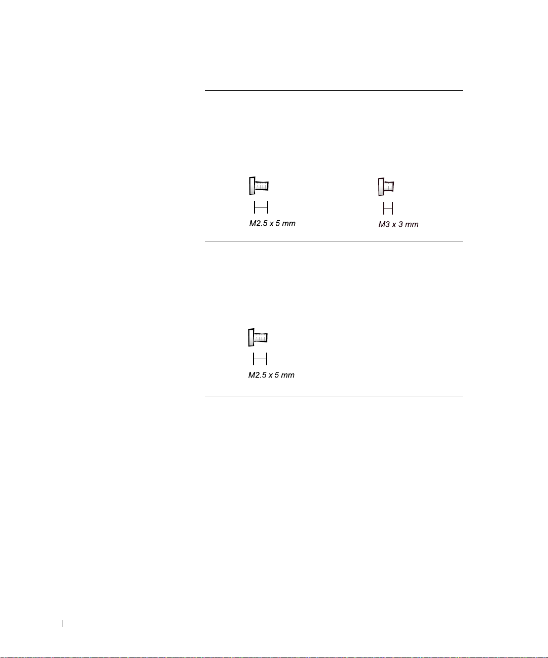
Screw Placement
System Board to
Bottom Case
Assembly:
(10 each)
www.dell.com | support.dell.com
Display Panel to
Support Bracket:
(12.1-inch display panel onl y)
(4 each)
Display Assembly
Latch:
(2 each for 14.1-inch XGA
display panels)
14 Before You Begin
Page 15
SECTION 2
Removing and Replacing Parts
Components
Hard Drive
Memory Module
Mini-PCI Card Assembly
Keyboard Assembly
Removing the Display Assembly
Display Assembly Latch
Hinge Covers
Palmrest Assembly
Microprocessor Thermal Cooling Assembly
www.dell.com | support.dell.com
Hybrid Cooling Fan
Microprocessor Modul e
Reserve Battery
Speaker Assemblies
System Board Assembly
Battery and Modular Bay Latch Assemblies
Page 16
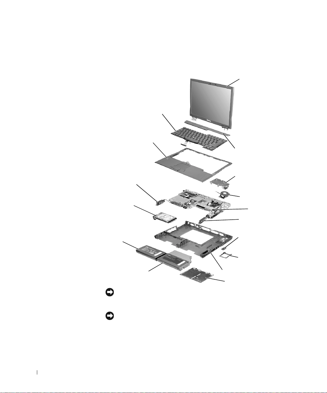
Components
Exploded View
display-assembly
top cover
keyboard
www.dell.com | support.dell.com
palmrest assembly
center control cover
left speaker/antenna
assembly
hard drive
main battery
modular bay device
NOTICE: Only a certified service technician should perform repairs on your
system. Damage due to servicing that is not authorized by Dell is not covered
by your warranty.
NOTICE: Unless otherwise noted, each procedur e in this man ual assu mes that
a part can be replaced by performing the removal procedure in reverse order.
thermal cooling assembly
hybrid cooling fan
system board
right speaker/antenna
assembly
modem and NIC
connector covers
fan guard
bottom case assembly
memory module cover
16 Removing and Replacing Parts
Page 17
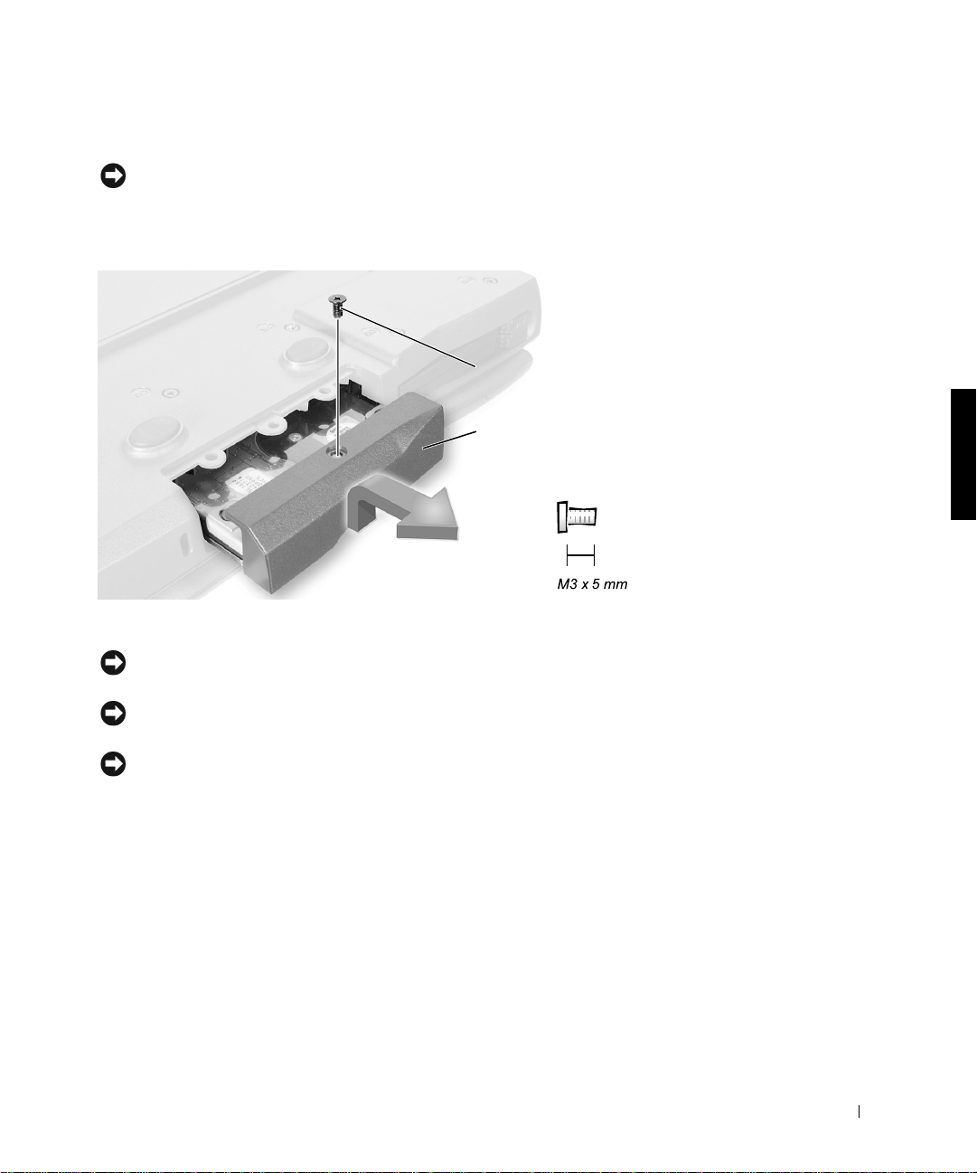
Hard Drive
NOTICE: The hard drive is very sensitive to shock. Handle the assembly by its
edges (do not squeeze the top of the hard drive case), and avoid dropping it.
Hard Drive
bottom of computer
M3 x 5-mm screw
hard drive door
Removing the Hard Drive
NOTICE: Disconnect the computer and any attached devices from electrical
outlets, and remove any installed batteries.
NOTICE: To avoid ESD, ground yourself by using a wrist grounding strap or
by touching an unpa inted metal surface on the computer.
NOTICE: Read "Preparing to Work Inside the Computer" before performing
the following procedure.
1
Remove the M3 x 5-mm screw from the hard drive door.
2 Slide the drive door up until the drive assembly tabs disengage from
the door slots in the botto m case assembly.
3 Pull the hard drive straight out of the bottom case assembly.
Replacing the Hard Drive
1 Gently push the hard drive into the drive bay until the drive door is
flush with the computer case.
Removing and Replacing Parts 17
Page 18
2 Push down on the drive door until it snaps into place.
3 Replace the M3 x 5-mm screw in the hard drive door.
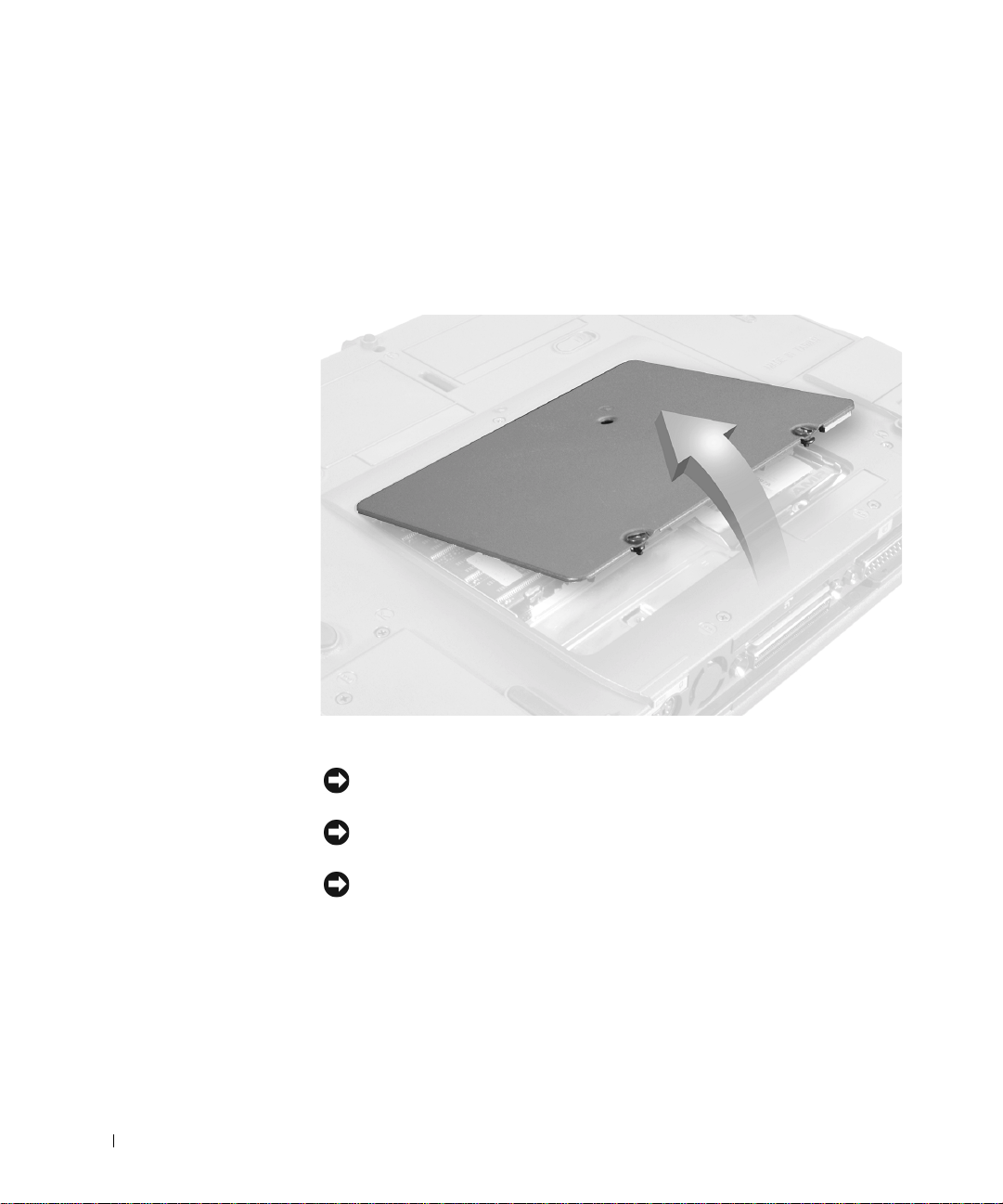
Memory Module
Memory Module Cover
www.dell.com | support.dell.com
Removing the Memory Module Cover
NOTICE: Disconnect the computer a nd any attached devices from electrical
outlets, and remove any installed batteries.
NOTICE: To avoid ESD, ground yourself by using a wrist grounding strap or
by touching an unpainted metal surface on the computer.
NOTICE: Read "Preparing to Work Inside the Computer" before per forming
the follo wing proce dure.
Remove the memory module cover:
1
a Use a coin or flat-blade screwdriver to release the two captive
b Place your finger under the cover at the indentation and lift and
18 Removing and Replacing Parts
screws that secure the memory module cover.
slide the cover open.
Page 19
NOTE: The screw labeled with the "circle K" in the middle of the memory
module cover secures the keyboard assembly and do es not secure the
memory module cover.
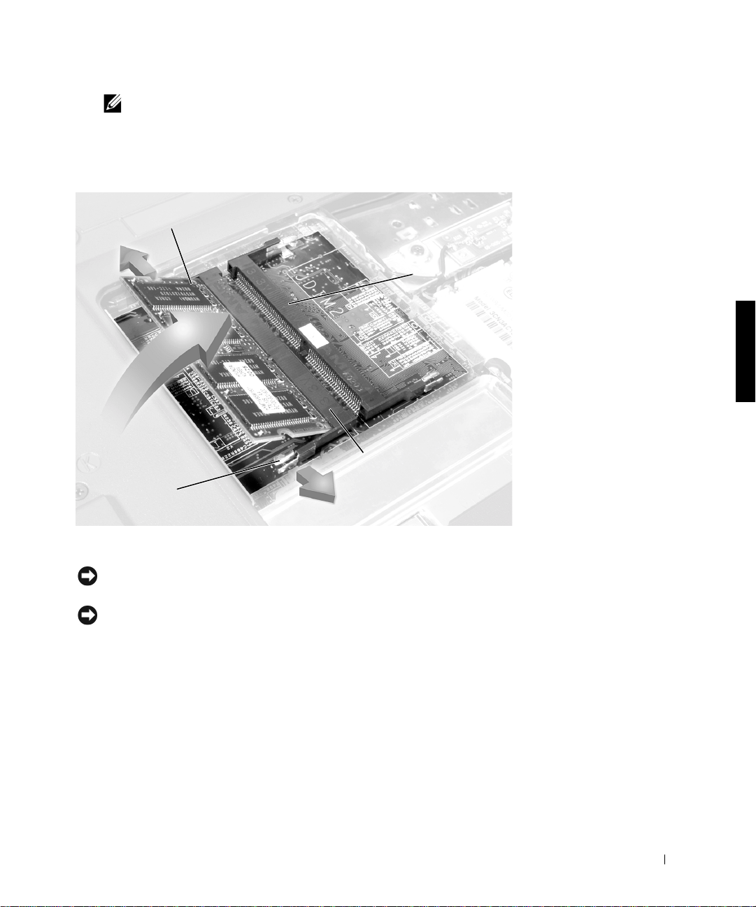
Memory Modules
JDIM 1
inner tabs
(2 per socket)
JDIM 2
memory
module sockets (2)
Removing the Memory Modules
NOTICE: Disconnect the computer and any attached devices from electrical
outlets, and remove any installed batteries.
NOTICE: To avoid ESD, ground yourself by using a wrist grounding strap or
by touching an unpa inted metal surface on the computer.
Removing and Replacing Parts 19
Page 20

NOTICE: Read "Preparing to Work Inside the Computer" before per forming
the follo wing proce dure.
Remove the memory module cover.
1
2 To release a memory module from its socket, spread apart the inner
tabs of the memory module socket just far enough for the memory
module to disengage from the socket. The module should pop up
slightly.
3 Lift the memory module out of its socket.
Replacing the Memory Modules
www.dell.com | support.dell.com
1 If you only have one memory module, install it in the socket labeled
“JDIM1.” Install a second memory module in the socket labeled
“JDIM2.”
NOTE: Memory modules are keyed, or designed to fit into their sockets,
in only one direction.
NOTICE: The memory module must be inserted at a 45-d egr ee angle t o avoi d
damaging the connector.
2
Align the memory module’s edge connector with the slot in the center
of the memory module socket. With the module at a 45-degree angle,
press the memory module’s edge connector firmly into the memory
module socket.
3 Pivot the memory module down until it clicks into place. If you do not
hear a click, remove the memory module and reinstall it.
4 Insert the tabs on the memory module cover into the bottom case
assembly. Rotate the memory module cover down and tighten the two
captive screws.
Mini-PCI Card Assembly
You must remove the optional mini-PCI card assembly before the system
board assembly can be removed. A mini-PCI card assembly may consi st of a
modem, a NIC, a modem and NIC combination, or a wireless NIC. A
modem, NIC, or modem and NIC combination must be connected to the
wiring harness as appropriate; a wireless NIC must be connected to the
system’s internal antenna.
20 Removing and Replacing Parts
Page 21

Mini-PCI Card Assembly Using Interface Cables
socket
Mini PCI Wireless NIC Assembly Using Antenna Cable
connection to
internal antenna
modem connector
NIC connector
mini-coax
antenna cable
Removing and Replacing Parts 21
Page 22

Removing the Mini-PCI Card Assembly
NOTICE: Disconnect the computer a nd any attached devices from electrical
outlets, and remove any installed batteries.
NOTICE: To avoid ESD, ground yourself by using a wrist grounding strap or
by touching an unpainted metal surface on the computer.
NOTICE: Read "Preparing to Work Inside the Computer" before per forming
the follo wing proce dure.
1
Remove the memory module cover.
2 T o releas e the mi ni-PCI car d as sembly from its sock et, spr ead apart t he
metal securing tabs until the assembly pops up slightly.
www.dell.com | support.dell.com
3 Lift the mini-PCI card assembly out of its socket and disconnect any
attached cables.
Replacing the Mini-PCI Card Assembly
NOTICE: The mini-PCI card must be inserted at a 45-degree angle to avoid
damaging the connector.
NOTICE: The mini-PCI card is keyed, or designed to fit into its socket, in o nly
one direction. Do not force the connecti on.
1
Align the mini-PCI card with the socket at a 45-degree angle, and press
the mini-PCI card firmly into th e socket.
2 Depending on the type of mini-PCI card you are installing, either
connect the interface cables to the mini-PCI card, or connect the
mini-coax antenna cable from the mini-PCI card to the internal
antenna.
3 Lower the mini-PCI card until it snaps into the metal securing tabs.
Replace the memory module cover.
4
22 Removing and Replacing Parts
NOTE: If you are installing a wireless NIC, fold and tuck the unused
interface cables into the slot so they do not interfere with the cover.
NOTE: A modem-only mini-PCI card has one connector; place the unused
NIC connector under the mini-PC I card.
Page 23

Keyboard Assembly
Removing the Keyboard Screws
M2.5 x 12-mm screws (5)
Removing the Keyboard Assembly
NOTICE: Disconnect the computer and any attached devices from electrical
outlets, and remove any installed batteries.
NOTICE: To avoid ESD, ground yourself by using a wrist grounding strap or
by touching an unpa inted metal surface on the computer.
NOTICE: Read "Preparing to Work Inside the Computer" before performing
the following procedure.
Remove the hard drive.
1
2 Turn the computer over, and remove the five M2.5 x 12-mm screws
from the holes labeled "circle K."
3 Turn the computer over and open the display.
NOTICE: The key caps on the keyboard are fragile, easily dislodged, and
time-consuming to replace. Be careful when removing and handling the
keyboard.
Removing and Replacing Parts 23
Page 24

4 To release the keyboard from the palmrest assembly, use a small, flat-
blade screwdriver or plastic scribe to pull up on the scalloped edge of
the blank key on the keyboard.
NOTE: Removing the center control cover provides more room to free the
keyboard.
Keyboa rd
scalloped edge
of blank key
www.dell.com | support.dell.com
keyboard
Lift the keyboard straight up until it clears the keyboard boss support
5
track stick
palmrest
in the bottom case assembly.
6 Rotate the keyboard forward toward the front of the computer.
7 Rest the key face of the keyboard on the palmrest.
24 Removing and Replacing Parts
Page 25

Keyboard Connector
keyboard flex cable
8 Disconnect the keyboard flex cable from the interface connector on the
track stick cab le
system board assembly by pulling up on the connector.
NOTICE: Do not pull on the keyboard flex cable.
9 Remove the keyboard assembly from the bottom case assembly.
Replacing the Keyboard Assembly
1 Place the keyboard on the palmrest at the front of the computer with
the keys face down and the connector toward the back of the
computer.
NOTICE: To avoid damage to the connector pins, press the keyboard
connector evenly into the interface connector, and do not reverse the keyboard
connector.
Connect the keyboard flex cable to the interface connector on the
2
system board assembly.
3 Carefully turn the keyboard over and fit the keyboard into place.
Removing and Replacing Parts 25
Page 26

NOTICE: Position the keyboard flex cable so it is not pinched when you
replace the keyboard in the bottom case assembly.
Check that the keyboard is correctly installed. The keys should be flush
4
with the left and right surfaces of the palmrest.
5 Reinstall the five M2.5 x 12-mm screws in the holes labeled "circle K."
Removing the Display Assembly
NOTICE: You must remove the disp lay assembly before you remove the
palmrest assembly; the display assembly hinges pass through the back of the
palmrest assembly.
www.dell.com | support.dell.com
NOTE: Always remove and replace the display pa nel as a complete assembly.
NOTICE: Disconnect the computer and any attached devices from electrical
outlets, and remove any installed batteries.
NOTICE: To avoid ESD, ground yourself by using a wrist grounding strap or
by touching an unpainted metal surface on the computer.
NOTICE: Read "Preparing to Work Inside the Computer" before per forming
the follo wing proce dure.
26 Removing and Replacing Parts
Page 27

Display Assembly
)
M2 x 3-mm screws (2)
display-assembly top co ver
(14.1-inch display assembly shown
center control cover
EMI shield bracket
LCD flex cable connector
bottom case assembly
1
Remove the hard drive.
2 Remove the center control cover.
a Use a scribe to lift the right edge of the center control cover and
pry it loose from the bottom case assembly.
b Lift the center control cover up and away from the bottom case
assembly.
3 Close the display.
M2.5 x 5-mm
screws (5)
Removing and Replacing Parts 27
Page 28

4 From the back of the computer, remove the five M2.5 x 5-mm screws
labeled with the "circle D." There are two screws on the right hinge and
three screws on the left hinge.
5 Open the display assembly approximately 180 degrees and support the
display assembly so it does not open past this position.
6 Remove the two M2 x 3-mm screws that secure the EMI shield bracket
to the system board assembly.
7 Remove the flex cable EMI shield retention bracket that covers the
display-feed flex cable connector on the system board.
8 Pull straight up on the display-feed flex cable connector to disconnect
www.dell.com | support.dell.com
the connector from the system board (see "Display Assembly").
9 Lift the display assembly from the bottom case assembly.
NOTICE: When reconnecting the display-feed flex cable connector to the
system board, push down on the top left and right ends of the c onnector (see
"Reconnecting the Display-Feed Flex Cable Connector"). Pressing on the center
of the connector may damage resistors and compromise EMI protection in the
system.
Reconnecting the Display-Feed Flex Cable Connector
28 Removing and Replacing Parts
Page 29

14.1-Inch Display Assembly Bezel and Panel
rubber screw covers (6)
M2.5 x 5-mm screws (6)
display
panel
display assembly bezel
flex cable
retention bracket
display-feed flex cable
display-assembly top cover
M2 x 4-mm
screws (5)
Removing and Replacing Parts 29
Page 30

Removing the 14.1-Inch Display Assembly Bez el
NOTICE: Disconnect the computer a nd any attached devices from electrical
outlets, and remove any installed batteries.
NOTICE: To avoid ESD, ground yourself by using a wrist grounding strap or
by touching an unpainted metal surface on the computer.
NOTICE: Read "Preparing to Work Inside the Computer" before per forming
the follo wing proce dure.
1
Remove the hard drive.
2 Remove the display assembly.
www.dell.com | support.dell.com
3 Use the scribe to pry the six r u b ber screw covers out of th e screw holes
located on the bezel on the front of the display assembly.
4 Remove the six M2.5 x 5-mm screws located on the bezel on the front
of the display assembly.
NOTICE: To avoid damage to the bezel, do not bend the bezel while
separating it from the display-assembly top cover.
Use a plastic scribe to carefully separate the bezel from the
5
display-assembly top cover.
Removing the 14.1-Inch Display Panel
NOTICE: Disconnect the computer a nd any attached devices from electrical
outlets, and remove any installed batteries.
NOTICE: To avoid ESD, ground yourself by using a wrist grounding strap or
by touching an unpainted metal surface on the computer.
1
Remove the hard drive.
2 Remove the display assembly.
3 Remove the display assembly bezel.
4 Remove the hinge covers.
5 Remove the two M2 x 4-mm screws on the left side of the display
panel and the two M2 x 4-mm screws on the right side of the display
panel.
30 Removing and Replacing Parts
NOTE: If you have a Hitachi display p anel, remove the two M2 x 4-mm
screws from the center of the left side of the display panel.
Page 31

6 Remove the M2 x 4-mm screw that secures the display-feed flex cable
to the display assemb ly thr ough the black plastic flex cable retention
bracket (see "14.1-Inch Display Assembly Bezel and Panel").
7 Disconnect the bottom flex cable connector from the display-assembly
top cover and inverter connector by pulling straight up on the attached
pull tab.
8 Lift and rotate the top of the display panel out of the display-assembly
top cover.
Replacing the 14.1-Inch Display Panel
1 Place the bottom edge of the display panel in the bottom of the
display-assembly top cover and elevate the top of the panel with your
hand.
2 Place the display panel in the display-assembl y top cover.
3 Reinstall the five M2 x 4-mm screws that secure the display panel to
the display-assembly top cover.
Removing and Replacing Parts 31
Page 32

Removing the Display-Feed Flex Cable (14.1-Inch Display Panel )
Display-Feed Flex Cable
display panel connector
top flex cable connector
pull tab
bottom flex
www.dell.com | support.dell.com
cable connector
inverter
connector
NOTICE: Disconnect the computer a nd any attached devices from electrical
outlets, and remove any installed batteries.
NOTICE: To avoid ESD, ground yourself by using a wrist grounding strap or
by touching an unpainted metal surface on the computer.
NOTICE: Read "Preparing to Work Inside the Computer" before per forming
the follo wing proce dure.
Remove the hard drive.
1
2 Remove the display assembly.
3 Remove the display assembly bezel.
4 Remove the tape that covers the display panel connector.
5 Pull the top flex cable connector down and away to remove it from the
display panel connector.
32 Removing and Replacing Parts
Page 33

12.1-Inch Display Assembly Bezel and Panel
rubber screw cov ers (6)
M2.5 x 5-mm
screws (6)
M3 x 3-mm
screws (4)
display
panel
display assembly bezel
flex cable
retention brack e t
display-feed flex cable
display-assembly top cover
support
bracket
M2 x 4-mm
screws (5)
Removing and Replacing Parts 33
Page 34

Removing the 12.1-Inch Display Assembly Bez el
NOTICE: Disconnect the computer a nd any attached devices from electrical
outlets, and remove any installed batteries.
NOTICE: To avoid ESD, ground yourself by using a wrist grounding strap or
by touching an unpainted metal surface on the computer.
NOTICE: Read "Preparing to Work Inside the Computer" before per forming
the follo wing proce dure.
1
Remove the hard drive.
2 Remove the display assembly.
www.dell.com | support.dell.com
3 Use the scribe to pry the six r u b ber screw covers out of th e screw holes
located on the bezel on the front of the display assembly.
4 Remove the six M2.5 x 5-mm screws located on the bezel on the front
of the display assembly.
NOTICE: To avoid damage to the bezel, do not bend the bezel while
separating it from the display-assembly top cover.
Use a plastic scribe to carefully separate the bezel from the
5
display-assembly top cover.
Removing the 12.1-Inch Display Panel
NOTICE: Disconnect the computer a nd any attached devices from electrical
outlets, and remove any installed batteries.
NOTICE: To avoid ESD, ground yourself by using a wrist grounding strap or
by touching an unpainted metal surface on the computer.
1
Remove the hard drive.
2 Remove the display assembly.
3 Remove the display assembly bezel.
4 Remove the hinge covers.
5 Remove the four M3 x 3-mm screws on the front of the display panel
that secure the display panel to the support bracket.
6 Remove the M2 x 4-mm screw that secures the display-feed flex cable
to the display assemb ly thr ough the black plastic flex cable retention
bracket (see "12.1-Inch Display Assembly Bezel and Panel").
34 Removing and Replacing Parts
Page 35

7 Lift up the right side of the display panel, and pull the panel out of the
display-assembly top cover at an angle.
Replacing the Display-Assembly Top Cover
If you are replacing the display-ass em bly top cover, remove the support
bracket.
1 Remove the two M2 x 4-mm screws on the left side of the
display-assembly top cover and the two M2 x 4-mm screws on the right
side of the display-assembly top cover.
2 Lift the support bracket ou t of the display-assembly top cover.
Replacing the 12.1-Inch Display Panel
1 Place the left edge of the display panel against the left side of the
support bracket in the display-assembly top cover, and elevate the right
side of the panel with your hand.
2 Lay the display panel into the display-assembly top cover.
3 Reinstall the four M3 x 3-mm screws that secure the display panel to
the support bracket.
Removing and Replacing Parts 35
Page 36

Removing the Display-Feed Flex Cable (12.1-Inch Display Panel )
Display-Feed Flex Cable
bottom flex
cable connector
www.dell.com | support.dell.com
inverter
connector
NOTICE: Disconnect the computer a nd any attached devices from electrical
outlets, and remove any installed batteries.
NOTICE: To avoid ESD, ground yourself by using a wrist grounding strap or
by touching an unpainted metal surface on the computer.
NOTICE: Read "Preparing to Work Inside the Computer" before per forming
the follo wing proce dure.
pull tab
top flex
cable connector
display panel
connector
Remove the hard drive.
1
2 Remove the display assembly.
3 Remove the display assembly bezel.
4 Remove the four M3 x 3-mm screws that secure the display panel to
the support bracket (see “12.1-Inch Display Assembly Bezel and
Panel”).
5 Lift the bottom of the display panel out of the display-assembly top
cover.
36 Removing and Replacing Parts
Page 37

6 Disconnect the bottom flex cable connector from the inverter
connector by pulling straight up on the attached pull tab.
7 Remove the tape that covers the display panel connector.
8 Pull the top flex cable connector down and away to remove it from the
display panel connector.
Display Assembly Latch
NOTICE: Disconnect the computer and any attached devices from electrical
outlets, and remove any installed batteries.
NOTICE: To avoid ESD, ground yourself by using a wrist grounding strap or
by touching an unpa inted metal surface on the computer.
Display Assembly Latch for 14.1-Inch XGA Display Panels
display assembly latch
M2.5 x 5-mm
screws (2)
Removing the Display Assembly Latch
1 Remove the hard drive.
2 Remove the display assembly.
3 Remove the display assembly bezel.
Removing and Replacing Parts 37
Page 38

4 Remove the display assembly latch by removing the two M2.5 x 5-mm
screws that secure it to the display-assembly top cover.
Display Assembly Latch for 14.1-Inch SXGA+ and 12.1Inch Display Panels
display assembly latch
www.dell.com | support.dell.com
NOTICE: Do not remove the display assembly latch from 14.1-inch SXGA+
and 12.1-inch display panels. If the latc h is damaged, replace the
display-assembly top cover.
38 Removing and Replacing Parts
Page 39

Hinge Covers
Removing the Hinge Covers
Removing the Hinge Covers
1 Remove the display assembly.
2 Rotate the hinges forward at an angle of approximately 90 degrees to
the front of the display assembly.
3 To remove the hinge covers, slide th em off of the hi nges.
Removing and Replacing Parts 39
Page 40

Replacing the Hinge Covers
Hinge Covers
www.dell.com | support.dell.com
right hinge cover
right hinge cover
left hinge cover
left hinge cover
1
Attach the display assembly to the bot tom case assembly.
40 Removing and Replacing Parts
Page 41

2 Close the display assembly and snap the hinge covers in place over the
hinges.
NOTE: The right plastic hinge cover label includes an “R,” and the left
plastic hinge cover label includes an “L.” The hinge cover labels face the
back of the computer.
Palmrest Assembly
Removing the Palmrest Assembly Screws
M2.5 x 12-mm
screws (3)
M2 x 3-mm screws (2)
Removing the Palm rest Assembly
NOTICE: Disconnect the computer and any attached devices from electrical
outlets, and remove any installed batteries.
NOTICE: To avoid ESD, ground yourself by using a wrist grounding strap or
by touching an unpa inted metal surface on the computer.
Removing and Replacing Parts 41
Page 42

NOTICE: Read "Preparing to Work Inside the Computer" before per forming
the follo wing proce dure.
Remove the hard drive.
1
2 Remove the keyboard.
NOTICE: You must remove the disp lay assembly before you remove the
palmrest assembly; the display assembly hinges pass through the back of the
palmrest assembly.
Remove the display hinge cover and display assembly.
3
4 Turn the computer over and remove the three M2.5 x 12-mm screws
that are labeled with a "circle P."
www.dell.com | support.dell.com
5 Remove the two M2 x 3-m m screws that are located in the hard drive
bay labeled with a "circle P."
6 Turn the computer over, and r emove the three M2 x 3-mm scr ews that
secure the palmrest to the bottom case assembly.
• Remove the two M2 x 3-mm screws that are located on the back
edge of the bottom case assembly, underneath the display
assembly.
• Remove the M2 x 3-mm screw located underneath the keyboard,
on the right side of the bottom case assembly, next to the
microprocessor thermal cooling assembly.
7 Pull up on the pull tab that is attached to the palmrest flex cable
connector to remove it from the touch pad connector on the system
board assem bly.
42 Removing and Replacing Parts
Page 43

Palmrest Assembly
M2 x 3-mm
screws (3)
palmrest assembly
palmrest flex cable
bottom case
assembly
touch pad connecto r
8 Using the plastic scribe along the edge of the plas tic, remove the
palmrest assembly from the bottom case a ssembly.
Removing and Replacing Parts 43
Page 44

Microprocessor Thermal Cooling Assembly
Microproce ssor Thermal Coolin g Assembly
captive screws (4)
www.dell.com | support.dell.com
microprocessor thermal cooling assembly
Removing the Microprocessor Thermal Cooling Assembly
NOTICE: Disconnect the computer a nd any attached devices from electrical
outlets, and remove any installed batteries.
NOTICE: To avoid ESD, ground yourself by using a wrist grounding strap or
by touching an unpainted metal surface on the computer.
NOTICE: Read "Preparing to Work Inside the Computer" before per forming
the follo wing proce dure.
1
Remove the hard drive.
2 Remove the keyboard screws.
44 Removing and Replacing Parts
Page 45

3 Turn the computer over, lift the keyboard up, rotate it forward toward
the front of the computer, and place it face down on the palmrest.
4 Loosen the four captive screws securing the microprocessor thermal
cooling assembly.
5 Remove the microprocessor thermal cooling assembly from the system
board assem bly.
NOTICE: When reattaching the microprocessor thermal coo ling assembly,
tighten the captive screws in consecutive order, from 1 to 4.
Hybrid Cooling Fan
Hybrid Cooling Fan
M2.5 x 5-mm screws (2)
M2 x 3-mm screw (1)
hybrid cooling fan
Removing and Replacing Parts 45
Page 46

Removing the Hybrid Cooling Fan
1 Remove the hard drive.
2 Remove the keyboard assembly.
3 Remove the display assembly.
4 Remove the palmrest assembly.
5 Remove the thermal cooling assembly.
6 Remove the two M2.5 x 5-mm screws and one M2 x 3-mm screw that
secure the hybrid cooling fan to the system board.
www.dell.com | support.dell.com
7 Disconnect the fan power cable from the system board interface
connector and remove the hybrid cooling fan.
NOTE: The fan power cable is long, and can be pulled out from under the
EMI shield to provide access to the connector.
NOTICE: Do not block the keyboard screw hole when reinserting the fan
cable.
46 Removing and Replacing Parts
Page 47

Microprocessor Module
Microproce ssor Modules
NOTICE: Hold the microprocessor down while turning the cam screw to
prevent intermittent contact between the cam screw and microprocessor.
perpendicular
screwdriver
ZIF socket
pin-1 corner
processor die
(do not touch)
perpendicular
screwdriver
ZIF socket
cam screw
cam screw
l
o
c
k
type I ZIF socket
type II ZIF socket
Removing the Microprocessor Module
NOTICE: Disconnect the computer and any attached devices from electrical
outlets, and remove any installed batteries.
NOTICE: To avoid ESD, ground yourself by using a wrist grounding strap or
by touching an unpa inted metal surface on the computer.
NOTICE: Read "Preparing to Work Inside the Computer" before performing
the following procedure.
pin-1 corner
processor die
(do not touch)
l
o
c
k
Remove the hard drive.
1
2 Remove the keyboa rd assembly.
NOTICE: To ensure maximum cooling for the mi croprocessor, do not touch
the heat transfer areas on the thermal cooling assembly. The oils in your skin
reduce the heat transfer capability of the thermal pads.
Removing and Replacing Parts 47
Page 48

3 Remove the microprocessor thermal cooling assembly.
NOTICE: When removing the microprocesso r mod ule, pull the module
straight up. Be careful not to bend the pins on the microprocessor module.
Remove the microprocessor module.
4
NOTICE: To avoid damage to the microprocessor , hold the screwdriver so that
it is perpendicular to the microprocessor when removing the cam screw (see
“Microprocessor Modules”).
a Use a small flat-head screwdriver and rotate the ZIF socket cam
screw counter-clockwise 180 degrees to loosen the ZIF socket.
The ZIF socket cam screw secures the microprocessor assembly to
www.dell.com | support.dell.com
the system board assembly. Take note of the arrow on the ZIF
socket cam screw (see "Microprocessor Modu les").
NOTE: Your system ha s a type I or type II ZIF socket.
b Use a microprocessor extraction tool to remove the microprocessor
module.
Replacing the Microprocessor Module
NOTICE: Seating the microprocessor module properly in the ZIF socket does
not require force.
NOTICE: A microprocessor module that is not properly seated can result in
an intermittent connection, or permanent damage to the microprocessor and
ZIF socket.
Align the pin-1 corner of the microprocessor module with the pin-1
1
corner of the microprocessor socket on the system board and insert the
microprocessor module.
NOTICE: You must position the microprocessor module correctly in the ZIF
socket to avoid permanent damage to the module and the socket.
When the microprocessor module is correctly seated, all four corners
are aligned to the same height. If one or more corners of the module
are higher than the others, the module is not seated correctly.
NOTICE: Hold the microprocessor down while turning the cam screw to
prevent intermittent contact between the cam screw and microprocessor (see
“Microprocessor Modules”).
Tighten the ZIF socket by turning the cam screw clockwise to secure
2
the microprocessor module to the system board assembly.
48 Removing and Replacing Parts
Page 49

3 Update the BIOS using a flash BIOS update program diskette or CD.
NOTE: For instructions to update or flash the BIOS, see the
Portable Computer BIOS Update Gui de
.
Dell
Reserve Battery
NOTICE: The reserve battery provides powe r to the computer’s RTC and
NVRAM when the computer is turned off. Removing the battery causes the
computer to lose the date and time information as well as all user-specified
parameters in the BIOS. If possible, make a copy of this information before
you remove the reser ve battery.
Removing the Reserve Battery
NOTICE: Disconnect the computer and any attached devices from electrical
outlets, and remove any installed batteries.
NOTICE: To avoid ESD, ground yourself by using a wrist grounding strap or
by touching an unpa inted metal surface on the computer.
NOTICE: Read "Preparing to Work Inside the Computer" before performing
the following procedure.
Rese rve Ba tter y
reserve battery
reserve battery
cable
reserve battery
connector
Removing and Replacing Parts 49
Page 50

1 Remove the hard drive.
2 Remove the memory module cover.
3 Disconnect the reserve battery cable from the connector on the system
board assembly located next to the reserve battery.
NOTE: If the reserve battery is not located on the EMI shield as shown in
“Reserve Battery,” contac t Dell technical support.
Remove the reserve battery from the EMI shield:
4
a Pry the reserve battery free from the foam pad.
b Remove the remnants of the foam pad from the EMI shield.
www.dell.com | support.dell.com
Replacing the Reserve Battery
1 Connect the reserve battery cable to the connector on the system
board.
2 Po sition the r ese rve batte ry on the EM I shield n ext to the c onnec tor to
minimize slack in the cable.
3 Update the BIOS using a flash BIOS update program diskette or CD.
NOTE: For instructions to update or flash the BIOS, see the
Portable Computer BIOS Update Guide.
Dell
Speaker Assemblies
The speakers are located on the front left and right sides of the bottom case
assembly. Each speaker assembly is marked with a right or left label. Take
note of the speaker cable routing in the bottom case assembly so you can
replace it correctly.
50 Removing and Replacing Parts
Page 51

Routing the Left Speaker Cable
Removing the Speaker Assemblies
NOTICE: Disconnect the computer and any attached devices from electrical
outlets, and remove any installed batteries.
NOTICE: To avoid ESD, ground yourself by touchi ng an unpainted metal
surface or by using a wrist grounding strap.
NOTICE: Read "Preparing to Work Inside the Computer" before performing
the following procedure.
NOTICE: Make note of the speaker and antenna wire routing so you can
replace them properly under their routing clips.
Removing and Replacing Parts 51
Page 52

Speaker Assemblies
antenna
cable
in-line connector
www.dell.com | support.dell.com
left speaker
mounting ring
left speaker holder
antenna cable
52 Removing and Replacing Parts
right speaker holder
mounting ring
right speaker
Page 53

1 Remove the hard drive.
2 Remove the keyboa rd assembly.
3 Remove the display assembly.
4 Remove the palmrest assembly.
5 Disconnect the speaker interface cable connectors.
NOTICE: Do not pull the antenna cable when removing the speaker (see
“Speaker Assemblies”).
Remove the speaker assemblies by pulling them straight up and out of
6
the bottom case assem bly
NOTICE: Handle the speaker assemblies and speakers with care to avoid
damaging the speaker cones.
NOTE: The left speaker has an in-line connector, and its cable is longer
than the right speaker.
Replacing the Speaker Assembly
1 To replace the speaker assembly, place the mounting ring over the
front palmrest screw post.
NOTICE: Make sure the speaker wires are under their routing clips. Route the
left speaker w ire properly between the battery bay and hard drive area.
Slide the speaker assembly down in to the bottom case assembly.
2
NOTE: Speakers face out in the bottom case assembly holders.
System Board Assembly
The system board’s BIOS chip contains the system’s service tag number,
which is also visible on a bar-code label on the bottom of the computer. The
replacement kit for the system board assembly includes a CD that provides
a utility for transferring the service tag number to the replacement system
board assem bly.
Removing and Replacing Parts 53
Page 54

Removing the System Board Assembly Screws
fan guard
www.dell.com | support.dell.com
M2.5 x 5-mm
screws (9)
Removing the System Board
NOTICE: Disconnect the computer a nd any attached devices from electrical
outlets, and remove any installed batteries.
NOTICE: To avoid ESD, ground yourself by using a wrist grounding strap or
by periodically touching an unpainted metal on the computer.
NOTICE: Read "Preparing to Work Inside the Computer" before per forming
the follo wing proce dure.
1 Remove the hard drive.
2 Remove the keyboard assembly.
3 Remove the display assembly.
4 Remove the palmrest assembly.
5 Remove the thermal cooling assembly.
6 Remove the microprocessor.
7 Ve r ify that all PC Cards or plastic blanks are removed from the PC
Card slot.
54 Removing and Replacing Parts
Page 55

8 Ver i f y tha t the PC Card ejectors do not extend from the PC Card slot.
9 Turn the computer over, and remove the six M2.5 x 5-mm screws
labeled with a "circle B" that secure the system board assembly to the
bottom case assembly.
10 Remove the three M2.5 x 5-mm screws labeled with a "circle B" that
secure the fan guard to the bottom case assembly. The fan guard is
located on the right of the bottom case assembly.
System Board Assembly
M2.5 x 5-mm screw
Turn the bottom case assembly over and remove the M2.5 x 5-mm
11
screw, which is identified by a white "circle B" and arrow on a red label
attached to the top of the battery connector on the front center of the
system board.
12 Remove the speakers from the bottom case assembly.
Removing and Replacing Parts 55
Page 56

13 Pull the right side of bottom case assembly, next to the external
headphone and microphone connectors, away from the system board
assembly as you simultaneously lift the front of the system board
assembly out and away from the bottom case assembly.
Replacing the System Board
1 Install the microprocessor on the replacement system board.
2 Connect the r ig h t a n d lef t sp e aker to the replacement sys t e m board.
3 Install the replacement system board.
a Insert the external microphone and headphone connectors
www.dell.com | support.dell.com
4 Replace the memory modules, mini-PCI card, speaker assemblies, and
through the plastic botto m case assembly.
b Replace the nine M2.5 x 5 -mm scr ews, starting on the right side of
the bottom case assembly.
c Replace the fan guard cover, inserting the tab into the bottom case
assembly and replace the three M2.5 x 5-mm screws (see
“Removing the System Board Assembly Screws”). If you replace
the screw opposite the tab first, it makes it easier to insert and
replace the other two screws.
the thermal cooling assembly removed from the old system board.
NOTE: Be sure to route cables so that they will not be crimped or pinched
when the complete assembly is put back together.
5
Replace the palmrest assembly, the display assembly, the keyboard
assembly, and the hard drive.
6 Replace the modular bay devices and any PC Cards or plastic blanks in
the PC Card slot.
7 Insert the diskette or CD that accompanied the replacement system
board assembly into the ap propriate drive, and turn on the computer.
Follow the instructions on the screen.
56 Removing and Replacing Parts
NOTE: After replacing the sys t em board assembly, be sure to enter the
system’s service tag number into the BIOS of the replacement system
board assembly.
Page 57

Battery and Modular Bay Latch Assemblies
Battery and Modular Bay Latch Assemblies
location of
snap tabs (2)
latch buttons (2)
bump
wear rib
slider
spring
bottom case assembly
Removing the Battery and Modular Bay Latch Assemblies
NOTICE: Disconnect the computer and any attached devices from electrical
outlets, and remove any installed batteries.
NOTICE: To avoid ESD, ground yourself by using a wrist grounding strap or
by touching an unpa inted metal surface on the computer.
Removing and Replacing Parts 57
Page 58

NOTICE: Read "Preparing to Work Inside the Computer" before per forming
the follo wing proce dure.
Remove the hard drive.
1
2 Remove the keyboard assembly.
3 Remove the display assembly.
4 Remove the palmrest assembly.
5 Remove the system board.
6 Remove the battery latch button from the bottom case assembly by
squeezing the snap tabs.
www.dell.com | support.dell.com
Apply pressure to the latch and spring while unsnapping the snap tabs
to prevent the latch assembly from coming loose from the case. If the
latch assembly does come loose from the case:
a Reinsert the spring onto the slider on the latch, and reinstall the
module latch into the holding features on the inside of the case.
b Ensure that the slider is inserted in its respective hole, that the
side of the la tch with th e tw o bum ps is fac in g th e b ack of th e ca se ,
and that the surface with the wear ribs is facing the bottom of the
case.
NOTE: The latch will not function properly if the slider is oriented
incorrectly.
Snap in the new latch butt on f rom the bottom of the base, making
7
certain the snap tabs are fully engaged in the latch.
8 Ensure that the newly installed latch moves smoothly and freely when
pushed and released.
9 Repeat steps 5 through 7 for the modular bay latch.
58 Removing and Replacing Parts
Page 59

Index
B
battery and modular bay latch
assemblies
removing, 57
D
display assembly
removing, 26
display assembly bezel
removing, 29, 33
display assembly bezel (12.1-
inch)
removing, 34
display assembly bezel (14.1-
inch)
removing, 30
display assembly latch
removing, 37, 38
display panel (12.1-inch)
removing, 34
replacing, 35
display panel (14.1-inch)
removing, 30
replacing, 31
display-assembly top cover
replacing, 35
display-feed flex cable
removing from 12.1-inch
display panel, 36
removing from 14.1-inch
display panel, 32
H
hard drive, 17
removing, 17
replacing, 17
hinge covers
removing, 39
replacing, 40
hybrid cooling fan
removing, 46
K
keybo ard , 2 3
removing, 23
replacing, 25
M
memory module, 18
removing, 19
replacing, 20
microprocessor module
removing, 47
replacing, 48
microprocessor thermal
cooling assembly
removing, 44
mini-PCI card, 2 0
removing, 22
replacing, 22
P
palmrest assembly
removing, 41
preparing to work inside the
computer, 10
R
recommended tools, 11
reserve battery
removing, 49
replacing, 50
S
screw identification and
tightening, 12
speaker assemblies
removing, 51
replacing, 53
Index 59
Page 60

system board
removing, 54
replacing, 56
system board assembly
removing, 47
system components, 16
T
thermal cooling assembly
removing, 44
60 Index
Page 61

Page 62

082EWX A01
P/N 82EWX Rev. A01
Printed in the U.S.A.
www.dell.com
support.dell.com
 Loading...