How it Works
Log In / Sign Up
Buy Points
How it Works
FAQ
Contact Us
Questions and Suggestions
Users
Dell
Loading...
I
Inspiron 7558
7
Inspiron 7559
4
Inspiron 7559-1240
Inspiron 7560
3
Inspiron 7567-8814
Inspiron 7567-9309
Inspiron 7567-9316
Inspiron 7567-9330
Inspiron 7567-9347
Inspiron 7568
70
Inspiron 7569
2
Inspiron 7570
56
Inspiron 7573
8
Inspiron 7577
Inspiron 7579
Inspiron 7580
Inspiron 7586
Inspiron 7590
9
Inspiron 7706
Inspiron 7706 2-in-1
4
Inspiron 7720
2
Inspiron 7737
31
Inspiron 7746
67
Inspiron 7777
Inspiron 7777-6412
Inspiron 7777-6429
Inspiron 7791
2
Inspiron 7791 2n1
Inspiron 8000
13
Inspiron 8100
14
inspiron 8200
13
Inspiron 8500
20
Inspiron 8600
26
Inspiron 910
48
Inspiron 9100
12
Inspiron 9200
8
Inspiron 9300
9
INSPIRON 9400
12
INSPIRON B120
6
Inspiron b130
13
Inspiron CPi
Inspiron CS
Inspiron Desktop
3
Inspiron duo
57
Inspiron E1405
2
Inspiron Gaming 7466
3
Inspiron Gaming 7467
3
Inspiron Gaming 7566
3
Inspiron Gaming 7567
3
Inspiron Gaming 7577
3
Inspiron i1200
Inspiron i2200
Inspiron M101z
Inspiron M102Z
19
Inspiron M301Z
54
Inspiron M4010
3
Inspiron M4040
28
Inspiron M411R
7
Inspiron M421R
11
Inspiron M431R
3
Inspiron M5010
28
Inspiron M501R
56
Inspiron M5040
44
Inspiron M5110
25
Inspiron M511R
48
Inspiron M521R
7
Inspiron M531R
3
Inspiron M731R
3
Inspiron Mini 10
10
Inspiron Mini 10 1010
66
Inspiron Mini 1012
60
Inspiron Mini 1018
56
Inspiron Mini 10 Ubuntu
Inspiron Mini 10v
61
Inspiron Mini 10v 1011
65
Inspiron Mini 10v 1018
52
Inspiron Mini 10v N
6
Inspiron Mini 10v N Ubuntu
Inspiron Mini 10v Ubuntu
Inspiron Mini 11
Inspiron Mini 1110
Inspiron Mini 11Z
Inspiron Mini 12
6
Inspiron Mini 1210
Inspiron Mini 12 Ubuntu
Inspiron Mini 9
6
Inspiron Mini 9 910
61
Inspiron Mini 9 Ubuntu
Inspiron Mini 9 XP
Inspiron Mini Duo
5
Inspiron Mini Duo 1090
54
Inspiron N3010
8
Inspiron N301Z
8
Inspiron N4010
10
Inspiron N4030
28
Inspiron N4050
Inspiron N4110
11
Inspiron N4120
3
Inspiron N5010
28
Inspiron N5020
28
Loading...
Loading...
Nothing found
Inspiron i1200
Service Manual
45 pgs
1.72 Mb
0
Table of contents
Loading...
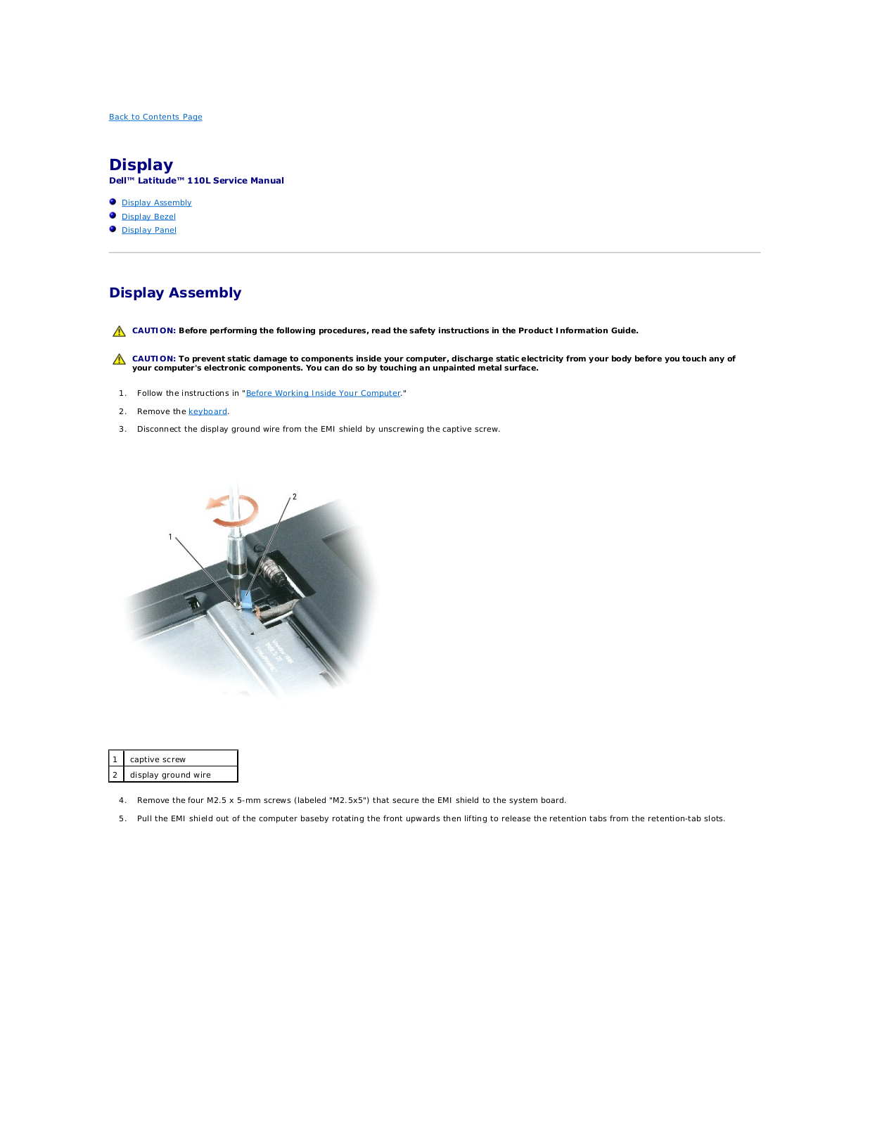
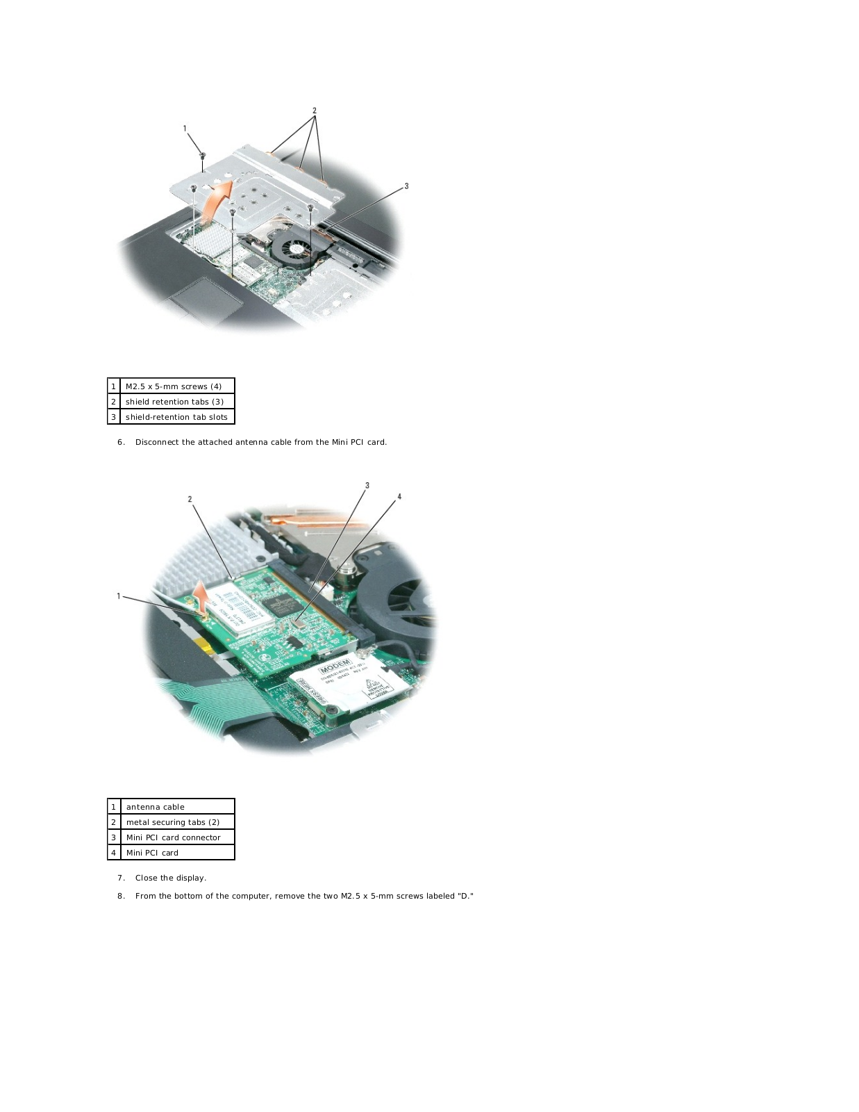
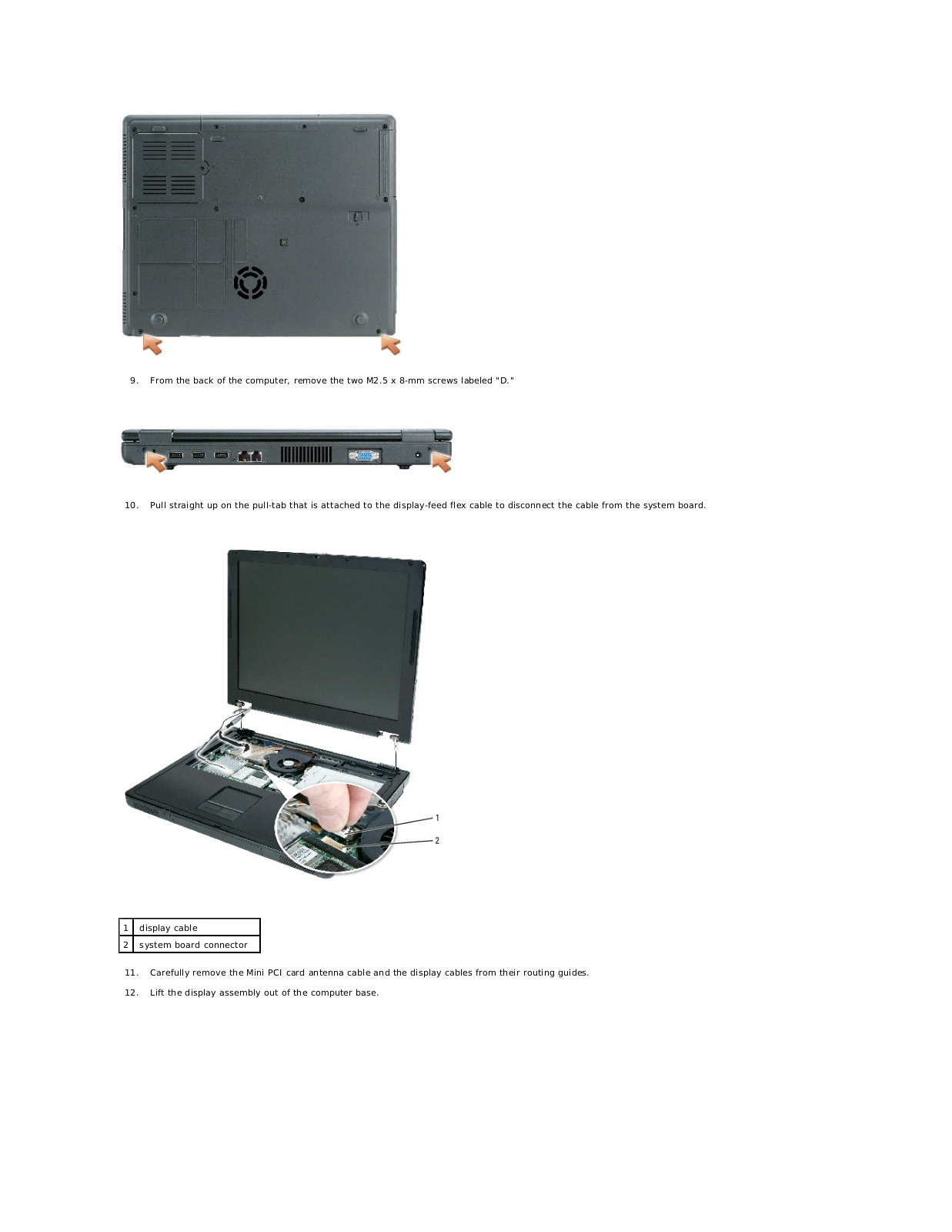
Dell Inspiron i1200, Inspiron i2200 Service Manual
...
Dell Service Manual
Download
Specifications and Main Features
Frequently Asked Questions
User Manual
Download
Loading...
+
31
hidden pages
Unhide
You need points to download manuals.
1 point = 1 manual.
You can buy points or you can get point for every manual you upload.
Buy points
Upload your manuals
 Loading...