

Dell Inspiron 5468 Owners Manual

Inspiron 14 5000
Service Manual
Computer Model: Inspiron 14-5468
Regulatory Model: P64G
Regulatory Type: P64G006

Notes, cautions, and warnings
NOTE: A NOTE indicates important information that helps you make
better use of your computer.
CAUTION: A CAUTION indicates either potential damage to hardware or
loss of data and tells you how to avoid the problem.
WARNING: A WARNING indicates a potential for property damage,
personal injury, or death.
© 2016 Dell Inc. All rights reserved. This product is protected by U.S. and international
copyright and intellectual property laws. Dell and the Dell logo are trademarks of Dell Inc. in
the United States and/or other jurisdictions. All other marks and names mentioned herein
may be trademarks of their respective companies.
2016 - 09
Rev. A00

Contents
Before working inside your computer........................... 10
Before you begin .....................................................................................10
Safety instructions...................................................................................10
Recommended tools.................................................................................11
Screw list................................................................................................. 12
After working inside your computer..............................13
Removing the battery................................................... 14
Procedure................................................................................................ 14
Replacing the battery...................................................16
Procedure................................................................................................16
Replacing the optical drive............................................17
Prerequisites............................................................................................ 17
Procedure................................................................................................ 17
Removing the optical drive...........................................20
Procedure............................................................................................... 20
Post-requisites........................................................................................ 20
Removing the keyboard................................................ 21
Prerequisites............................................................................................ 21
Procedure................................................................................................ 21
3

Replacing the keyboard................................................24
Procedure................................................................................................24
Post-requisites........................................................................................ 24
Removing the base cover.............................................25
Prerequisites........................................................................................... 25
Procedure............................................................................................... 25
Replacing the base cover............................................. 27
Procedure................................................................................................27
Post-requisites.........................................................................................27
Removing the coin-cell battery.................................... 28
Prerequisites............................................................................................28
Procedure................................................................................................28
Replacing the coin-cell battery.................................... 30
Procedure............................................................................................... 30
Post-requisites........................................................................................ 30
Removing the hard drive...............................................31
Prerequisites............................................................................................ 31
Procedure................................................................................................ 31
Replacing the hard drive.............................................. 34
Procedure................................................................................................34
Post-requisites........................................................................................ 34
Removing the memory modules...................................35
Prerequisites........................................................................................... 35
Procedure............................................................................................... 35
4

Replacing the memory modules................................... 37
Procedure................................................................................................37
Post-requisites........................................................................................ 38
Removing the wireless card......................................... 39
Prerequisites........................................................................................... 39
Procedure............................................................................................... 39
Replacing the wireless card.......................................... 41
Procedure................................................................................................ 41
Post-requisites......................................................................................... 41
Removing the computer base...................................... 42
Prerequisites............................................................................................42
Procedure................................................................................................42
Replacing the computer base.......................................47
Procedure................................................................................................47
Post-requisites........................................................................................ 47
Removing the optical-drive interposer......................... 49
Prerequisites........................................................................................... 49
Procedure............................................................................................... 49
Replacing the optical-drive interposer.......................... 51
Procedure................................................................................................ 51
Post-requisites......................................................................................... 51
Removing the heat-sink assembly................................52
Prerequisites........................................................................................... 52
Procedure............................................................................................... 52
5

Replacing the heat-sink assembly................................54
Procedure............................................................................................... 54
Post-requisites........................................................................................ 54
Removing the I/O board.............................................. 56
Prerequisites........................................................................................... 56
Procedure............................................................................................... 56
Replacing the I/O board...............................................58
Procedure............................................................................................... 58
Post-requisites........................................................................................ 58
Removing the system board.........................................59
Prerequisites........................................................................................... 59
Procedure............................................................................................... 60
Replacing the system board......................................... 64
Procedure............................................................................................... 64
Post-requisites........................................................................................ 65
Removing the power-adapter port............................... 66
Prerequisites........................................................................................... 66
Procedure............................................................................................... 66
Replacing the power-adapter port............................... 68
Procedure............................................................................................... 68
Post-requisites........................................................................................ 68
Removing the power-button board...............................70
Prerequisites............................................................................................70
Procedure................................................................................................70
6

Replacing the power-button board...............................72
Procedure................................................................................................72
Post-requisites........................................................................................ 72
Removing the speakers................................................ 74
Prerequisites............................................................................................ 74
Procedure................................................................................................74
Replacing the speakers................................................ 76
Procedure................................................................................................76
Post-requisites........................................................................................ 76
Removing the display assembly....................................77
Prerequisites............................................................................................ 77
Procedure................................................................................................77
Replacing the display assembly.................................... 81
Procedure................................................................................................ 81
Post-requisites......................................................................................... 81
Removing the palm-rest assembly............................... 83
Prerequisites............................................................................................83
Procedure............................................................................................... 84
Replacing the palm-rest assembly............................... 85
Procedure............................................................................................... 85
Post-requisites........................................................................................ 85
Removing the display bezel.......................................... 87
Prerequisites............................................................................................87
Procedure............................................................................................... 88
7

Replacing the display bezel.......................................... 89
Procedure............................................................................................... 89
Post-requisites........................................................................................ 89
Removing the camera..................................................90
Prerequisites........................................................................................... 90
Procedure............................................................................................... 90
Replacing the camera.................................................. 92
Procedure............................................................................................... 92
Post-requisites........................................................................................ 92
Removing the display panel..........................................94
Prerequisites........................................................................................... 94
Procedure............................................................................................... 94
Replacing the display panel.......................................... 97
Procedure................................................................................................97
Post-requisites.........................................................................................97
Removing the display hinges........................................99
Prerequisites........................................................................................... 99
Procedure............................................................................................... 99
Replacing the display hinges....................................... 101
Procedure...............................................................................................101
Post-requisites....................................................................................... 101
Removing the display cable........................................ 103
Prerequisites.......................................................................................... 103
Procedure..............................................................................................103
8

Replacing the display cable........................................ 105
Procedure..............................................................................................105
Post-requisites.......................................................................................105
Removing the display back-cover and antenna
assembly.....................................................................107
Prerequisites.......................................................................................... 107
Procedure..............................................................................................108
Replacing the display back-cover and antenna
assembly.................................................................... 109
Procedure..............................................................................................109
Post-requisites.......................................................................................109
Flashing the BIOS........................................................ 111
Diagnostics................................................................. 112
Getting help and contacting Dell................................. 114
Self-help resources.................................................................................114
Contacting Dell.......................................................................................114
9
GUID-5D3B1051-9384-409A-8D5B-9B53BD496DE8
Before working inside your computer
NOTE: The images in this document may dier from your computer
depending on the conguration you ordered.
GUID-B2521C24-A407-4ABB-8022-6D88B53F0B94
Before you begin
1 Save and close all open les and exit all open applications.
2 Shut down your computer. Click Start → Power → Shut down.
NOTE: If you are using a dierent operating system, see the
documentation of your operating system for shut-down instructions.
3 Disconnect your computer and all attached devices from their electrical outlets.
4 Disconnect all cables such as telephone cables and network cables, from your
computer.
5 Disconnect all attached devices and peripherals, such as keyboard, mouse, and
monitor, from your computer.
6 Remove any media card and optical disc from your computer, if applicable.
7 Close the display and turn the computer over.
GUID-71128823-CE64-4E17-9439-DEE95AF668C4
Safety instructions
Use the following safety guidelines to protect your computer from potential damage
and ensure your personal safety.
10
WARNING: Before working inside your computer, read the safety
information that shipped with your computer. For more safety best
practices, see the Regulatory Compliance home page at www.dell.com/
regulatory_compliance.
WARNING: Disconnect all power sources before opening the computer
cover or panels. After you nish working inside the computer, replace all
covers, panels, and screws before connecting to the electrical outlet.
CAUTION: To avoid damaging the computer, ensure that the work surface is
at and clean.
CAUTION: To avoid damaging the components and cards, handle them by
their edges, and avoid touching pins and contacts.
CAUTION: You should only perform troubleshooting and repairs as
authorized or directed by the Dell technical assistance team. Damage due to
servicing that is not authorized by Dell is not covered by your warranty. See
the safety instructions that shipped with the product or at www.dell.com/
regulatory_compliance.
CAUTION: Before touching anything inside your computer, ground yourself
by touching an unpainted metal surface, such as the metal at the back of
the computer. While you work, periodically touch an unpainted metal surface
to dissipate static electricity, which could harm internal components.
CAUTION: When you disconnect a cable, pull on its connector or on its pull
tab, not on the cable itself. Some cables have connectors with locking tabs
or thumb-screws that you must disengage before disconnecting the cable.
When disconnecting cables, keep them evenly aligned to avoid bending any
connector pins. When connecting cables, ensure that the ports and
connectors are correctly oriented and aligned.
CAUTION: Press and eject any installed card from the media-card reader.
GUID-DEA55279-6FE6-4A1F-A152-21F8A5572B33
Recommended tools
The procedures in this document may require the following tools:
• Phillips screwdriver
11

• Plastic scribe
GUID-12242442-3331-4D72-BFC5-7C7A83FD33AF
Screw list
The following table provides the list of screws that are used for securing dierent
components to the computer.
Component Secured to Screw type Quantity
Optical-drive
assembly
Optical-drive
bracket
Base cover Computer base M2.5x8 2
Hard-drive
assembly
Hard-drive bracket Hard drive M3x3 4
Wireless-card
bracket
Computer base Palm-rest assembly M2.5x5 13
Heat-sink assembly System board M2x3 3
I/O board Palm-rest assembly M2.5x5 1
System board Palm-rest assembly M2x3 1
Power-adapter port Palm-rest assembly M2x3 1
Power-button
board
Display hinges Palm-rest assembly M2.5x5 3
Display panel Display back-cover M2x3 4
Display hinges Display back-cover M2.5x2.5 big head 6
Display hinges Display back-cover M2x3 6
Computer base M2x5 1
Optical drive M2x3 2
Computer base M2.5x5 4
Wireless card M2x3 1
Palm-rest assembly M2x2 big head 1
12

GUID-06588814-2678-4667-9FF9-C009F4BCE185
After working inside your computer
CAUTION: Leaving stray or loose screws inside your computer may severely
damage your computer.
1 Replace all screws and ensure that no stray screws remain inside your computer.
2 Connect any external devices, peripherals, or cables you removed before working
on your computer.
3 Replace any media cards, discs, or any other parts that you removed before
working on your computer.
4 Connect your computer and all attached devices to their electrical outlets.
5 Turn on your computer.
13
GUID-D9015C06-6CEE-42EA-9215-9D0FD7B827D5
Removing the battery
WARNING: Before working inside your computer, read the safety
information that shipped with your computer and follow the steps in Before
working inside your computer. After working inside your computer, follow
the instructions in After working inside your computer. For more safety best
practices, see the Regulatory Compliance home page at
regulatory_compliance.
GUID-D41367B7-182E-4AEC-84C3-35058353EC72
Procedure
1 Close the display and turn the computer over.
2 Slide the battery-release latch to the unlock position.
www.dell.com/
14
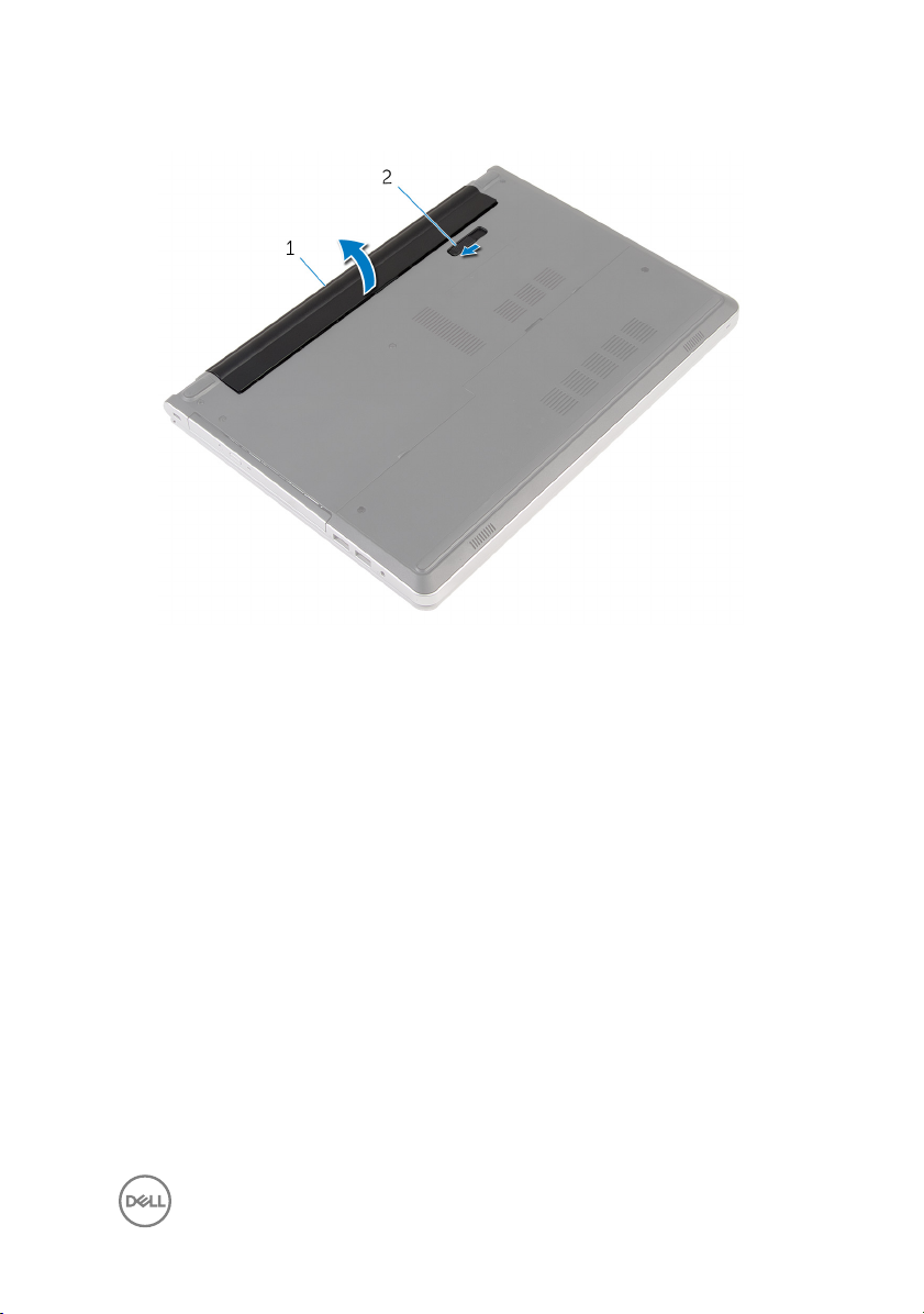
3 Lift the battery at an angle and remove the battery from the battery bay.
1 battery 2 battery-release latch
4 Turn the computer over, open the display, and press the power button for ve
seconds to ground the system board.
15
GUID-E15EE482-44FD-4E71-91FC-899D4B61532E
Replacing the battery
WARNING: Before working inside your computer, read the safety
information that shipped with your computer and follow the steps in Before
working inside your computer. After working inside your computer, follow
the instructions in After working inside your computer. For more safety best
practices, see the Regulatory Compliance home page at
regulatory_compliance.
GUID-84D588EC-A03D-45B0-B499-2E70A47E2634
Procedure
Slide the tabs on the battery into the slots on the battery bay and snap the battery
into place.
NOTE: The battery-release latch returns to the lock position if the battery is
installed properly.
www.dell.com/
16
GUID-01750DAC-3408-4912-B936-7DAA79351AA9
Replacing the optical drive
WARNING: Before working inside your computer, read the safety
information that shipped with your computer and follow the steps in Before
working inside your computer. After working inside your computer, follow
the instructions in After working inside your computer. For more safety best
practices, see the Regulatory Compliance home page at
regulatory_compliance.
GUID-9CCC3876-D33F-4A82-86C5-360E01796F9E
Prerequisites
Remove the battery.
GUID-4AEF5D38-7D9C-4954-9582-6684ED22FE52
Procedure
1 Remove the screw that secures the optical-drive assembly to the computer
base.
www.dell.com/
17
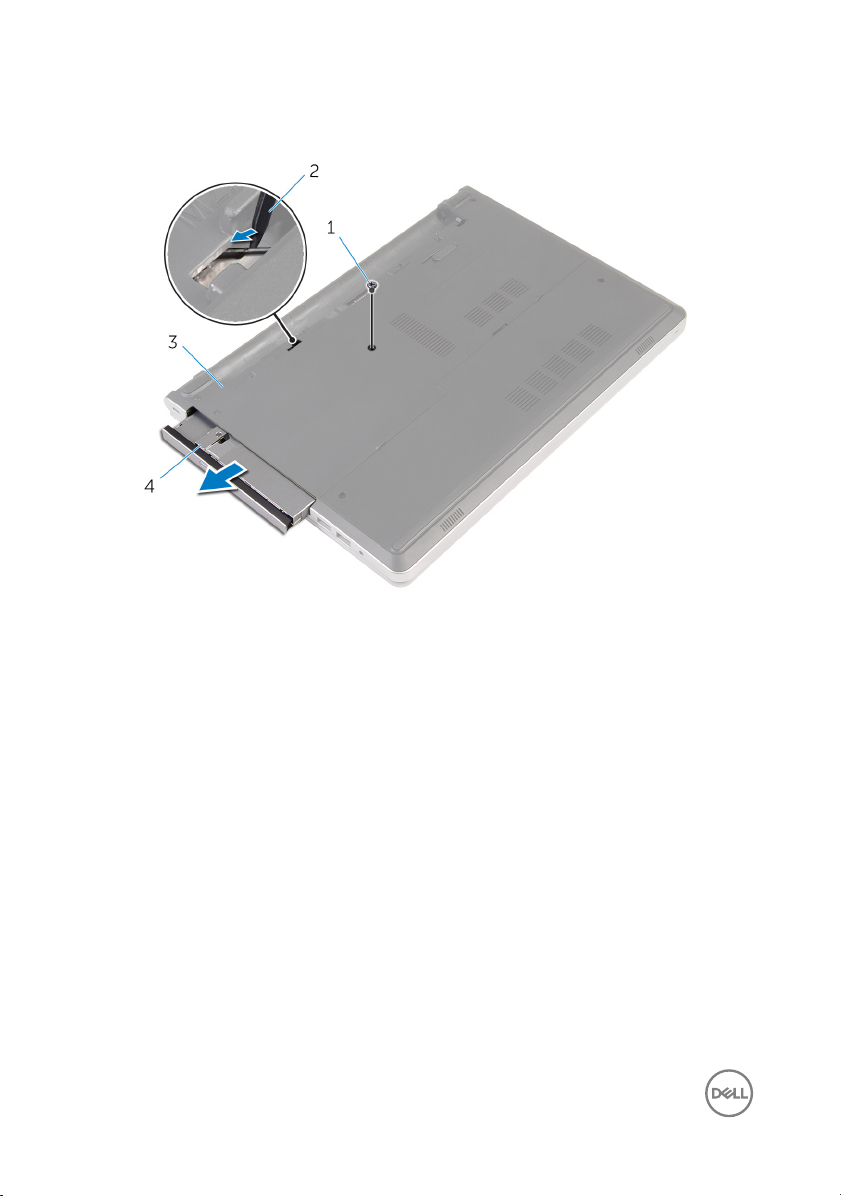
2 Using a plastic scribe, slide the optical-drive assembly out of the optical-drive
bay.
1 screw 2 plastic scribe
3 computer base 4 optical-drive assembly
3 Carefully pull the optical-drive bezel and remove it from the optical drive.
18
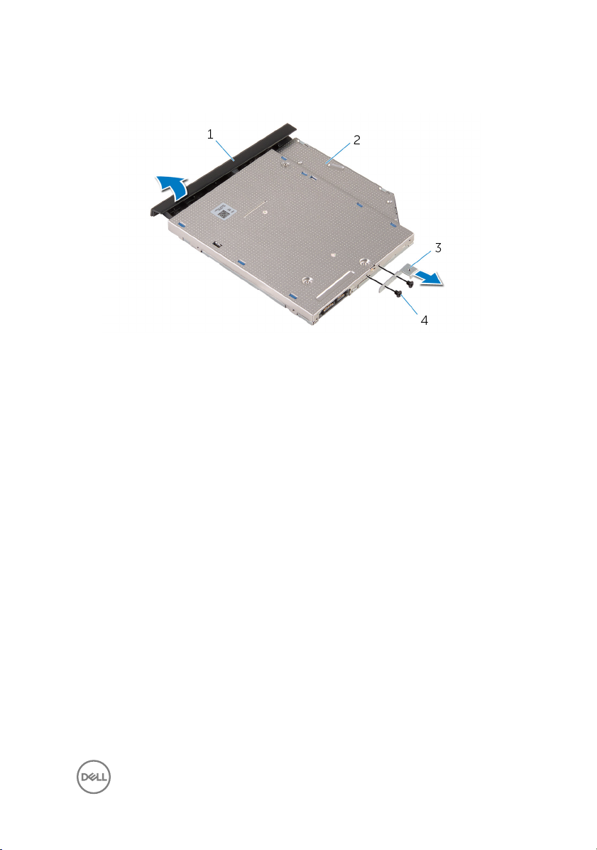
4 Remove the screws that secure the optical-drive bracket to the optical drive and
remove the optical-drive bracket.
1 optical-drive bezel 2 optical drive
3 optical-drive bracket 4 screws (2)
19
GUID-5F25DB7E-BE9A-49D8-A32A-AAD2A7EDBB9E
Removing the optical drive
WARNING: Before working inside your computer, read the safety
information that shipped with your computer and follow the steps in Before
working inside your computer. After working inside your computer, follow
the instructions in After working inside your computer. For more safety best
practices, see the Regulatory Compliance home page at
regulatory_compliance.
GUID-FE2985AD-343E-42C5-847C-6069119BC668
Procedure
1 Align the screw holes on the optical-drive bracket with the screw holes on the
optical drive.
2 Replace the screws that secure the optical-drive bracket to the optical drive.
3 Align the tabs on the optical-drive bezel with the slots on the optical-drive
assembly and snap the optical-drive bezel into place.
4 Slide the optical-drive assembly into the optical-drive bay and align the screw
hole on the optical-drive bracket with the screw hole on the computer base.
5 Replace the screw that secures the optical-drive assembly to the computer base.
www.dell.com/
GUID-EC9C783D-6E95-476D-950B-6739B063A45E
Post-requisites
Replace the battery.
20

GUID-5AE964CF-7958-4D31-BBA8-155C933167E8
Removing the keyboard
WARNING: Before working inside your computer, read the safety
information that shipped with your computer and follow the steps in Before
working inside your computer. After working inside your computer, follow
the instructions in After working inside your computer. For more safety best
practices, see the Regulatory Compliance home page at
regulatory_compliance.
GUID-04CAB8AA-16C0-4A52-824C-92928944B3F2
Prerequisites
Remove the battery.
GUID-60D3DD48-AE02-4FA9-B313-FA9D6C373D7E
Procedure
1 Turn the computer over and open the display as far as possible.
www.dell.com/
21
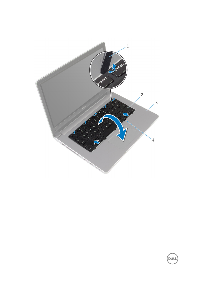
2 Insert a plastic scribe at the top of the keyboard, using it to gently release the
tabs that secure the keyboard to the palm-rest assembly.
1 plastic scribe 2 keyboard
3 palm-rest assembly 4 tabs (5)
3 Carefully turn the keyboard over and place it on the palm-rest assembly.
22
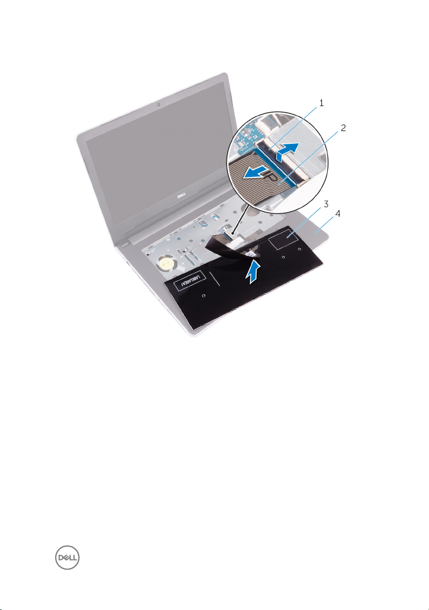
4 Open the latch and disconnect the keyboard cable from the system board.
1 latch 2 keyboard cable
3 keyboard 4 palm-rest assembly
5 Lift the keyboard, along with the cable, o the palm-rest assembly.
23
GUID-18204C76-DF75-4DB8-BD6F-EFA74576AAD7
Replacing the keyboard
WARNING: Before working inside your computer, read the safety
information that shipped with your computer and follow the steps in Before
working inside your computer. After working inside your computer, follow
the instructions in After working inside your computer. For more safety best
practices, see the Regulatory Compliance home page at
regulatory_compliance.
GUID-145778BA-DFBD-4DC2-8F80-BD1268D43DB5
Procedure
1 Slide the keyboard cable into the connector on the system board and close the
latch to secure the cable.
2 Carefully turn the keyboard over, slide the tabs on the keyboard into the bottom
slots on the palm-rest assembly, then snap the keyboard into place.
3 Close the display and turn the computer over.
GUID-422AC8F7-A740-4F6F-BF30-82E96492EF18
Post-requisites
www.dell.com/
Replace the battery.
24
GUID-98068FC2-1C1C-46DE-B3FA-DF9D488E9BA1
Removing the base cover
WARNING: Before working inside your computer, read the safety
information that shipped with your computer and follow the steps in Before
working inside your computer. After working inside your computer, follow
the instructions in After working inside your computer. For more safety best
practices, see the Regulatory Compliance home page at
regulatory_compliance.
GUID-97F13B2F-B13D-43F8-92D5-1A75EBC3DC5D
Prerequisites
1 Remove the battery.
2 Remove the optical drive.
3 Remove the base cover.
4 Follow the procedure from step 1 to step 3 in “Removing the hard drive”.
5 Remove the wireless card.
6 Remove the keyboard.
GUID-1F05B65F-19CC-4D09-9A66-5602BBD9B8A4
www.dell.com/
Procedure
1 Remove the screws that secure the base cover to the computer base.
25
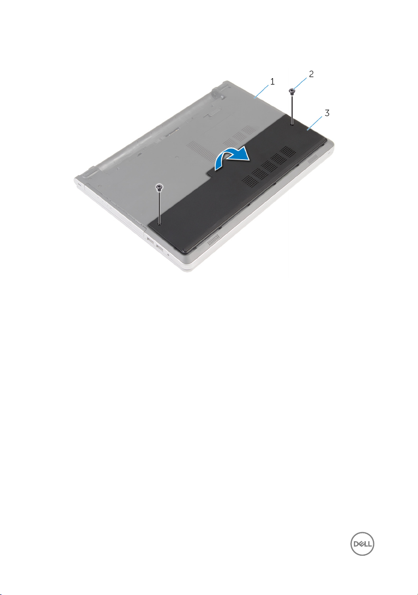
2 Using a plastic scribe, gently pry the base cover o the computer base.
1 computer base 2 screws (2)
3 base cover
26
GUID-27446428-82D7-4881-9220-9EB090B046EA
Replacing the base cover
WARNING: Before working inside your computer, read the safety
information that shipped with your computer and follow the steps in Before
working inside your computer. After working inside your computer, follow
the instructions in After working inside your computer. For more safety best
practices, see the Regulatory Compliance home page at
regulatory_compliance.
GUID-75756B5F-F671-48FD-B08F-DFEA1B459161
Procedure
1 Slide the tabs on the base cover into the slots on the computer base and snap
the base cover into place.
2 Replace the screws that secure the base cover to the computer base.
GUID-291486F4-CB8C-4DA0-A4EF-A47BE01213A0
Post-requisites
Replace the battery.
www.dell.com/
27
GUID-30EEBC49-DE3E-4C3F-8226-86CE5F32F388
Removing the coin-cell battery
WARNING: Before working inside your computer, read the safety
information that shipped with your computer and follow the steps in Before
working inside your computer. After working inside your computer, follow
the instructions in After working inside your computer. For more safety best
practices, see the Regulatory Compliance home page at
regulatory_compliance.
CAUTION: Removing the coin-cell battery resets the BIOS setup program’s
settings to default. It is recommended that you note the BIOS setup
program’s settings before removing the coin-cell battery.
GUID-D23A4BFB-4596-4E50-82D2-9A56E3615608
Prerequisites
1 Remove the battery.
2 Remove the base cover.
GUID-B5B1CDE2-B3C9-4833-ABC9-BDDC9E536F41
Procedure
www.dell.com/
Using a plastic scribe, gently pry the coin-cell battery out of the battery socket on the
system board.
28
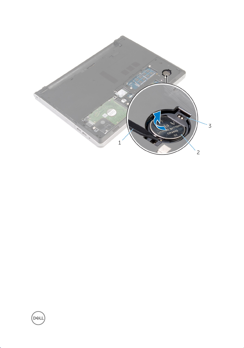
1 plastic scribe 2 coin-cell battery
3 battery socket
29
GUID-5E22F4A0-F01F-4522-8155-BE22A8CA6E5F
Replacing the coin-cell battery
WARNING: Before working inside your computer, read the safety
information that shipped with your computer and follow the steps in Before
working inside your computer. After working inside your computer, follow
the instructions in After working inside your computer. For more safety best
practices, see the Regulatory Compliance home page at
regulatory_compliance.
GUID-A6F2AC53-84FD-4F8E-9565-FB2C4F400108
Procedure
With the positive-side facing up, snap the coin-cell battery into the battery socket on
the system board.
GUID-AA93F32F-2905-4E30-9ACC-A0A4782F398C
Post-requisites
1 Replace the base cover.
2 Replace the battery.
www.dell.com/
30
 Loading...