

Page 1

'HOO
2SWL3OH[
*;
SUR
86(5·6*8,'(
6\VWHPV
®
Page 2

Information in this document is subject to change without notice.
1991–199 6 Del l Computer Corporation. All rights reserved.
Reproduc ti on in any manner what s oever without the wr itten permission of Dell Comput er Corporation is strictly forbidden.
Trademarks used in this text: Dell, the DELL logo, and OptiPlex are registered t rademarks and DellWa r e is a registered service mark of D ell
Computer Corporation; Intel and Pentium are registered trademar ks and Intel486, Intel386, IntelDX2, and IntelDX4 are trademarks of Intel
Corporation; Windo ws for W orkgroups is a trademark a nd Micr osof t, MS-DOS, Windows, and W indows N T are regi stered t rademarks of Micr osoft
Corporation; IBM and OS/2 are registered trademarks of International Business Machines Corporation; UNIX is a registered trade mark of U NIX
System Laboratories, Inc., a wholly owned subsidiary of Novell, Inc.; Novell and NetWare are registered trademarks of Novell, Inc.; VESA is a
registered trademar k and VL- Bu s is a trademark of Video Electronics Standards Association; 3Com is a registered trad emark of 3Com Corpor ation.
Other trademarks and trade na mes may be used in this document to refer to either the entitie s claiming the marks and names or their products.
Dell Computer Corporation disclaims any proprietary interest in trademarks and trade names other than its own.
Septembe r 1996 P/N 99153 Rev. A02
Page 3

Safety Instructions
se the foll owing safety guidelines to help pr otect
U
your computer’ s system from potentia l damage and to
ensure your own personal safety.
W
hen Using Your Computer System
As you use your computer syste m, observe the foll owing
safety gu idelin es:
To help avoid damaging your c omputer, be sure the
•
voltage s elec tion s wit ch on t he power s uppl y is set to
match t h e alternating current (AC) power available
at your location:
— 115 volts (V)/6 0 hertz (Hz) in mo st of North and
South America and some Far Eas tern countries
such as Japan, South Korea, and Taiwan
— 230 V/50 Hz in most of Europe, the Middle
East, and the Far East
Also be sure your monitor and attached peripherals
are electrically rated to operate with the AC power
available in your location.
To help avoid possi ble damage to the system board,
•
wait five seconds aft er turning off the system befo re
removing a component from the system board or disconnecting a peripheral device from the computer.
To help prevent electric shock, plug the computer
•
and peripheral power cables into properly grounded
power sources. These cables are equipped with 3prong plugs to en su re proper grounding. Do not use
adapter plu gs or remove the grounding prong from a
cable. If you must use an extension cable, use a 3wire cable with properly grounded plugs.
To help protect your comput er s ys tem from sudden,
•
tran sient in creases and decreases in ele ctrical power,
use a surge suppressor, line conditioner, or uninterruptible power supply.
Be sure nothing rests on your c omputer system’s
•
cables an d that the cables are not lo cated where they
can be stepped on or tripped over.
Do not spill food or liquids on your computer. If the
•
computer gets wet, consult your
Troublesh ooting Guide.
Do not push any objects into the openings of your
•
computer. Doing so can cause fire or electric shock
by shorting out interior components.
Keep your computer away from radiators and heat
•
sources. Also, do not block cooling vents. Avoid
placing loose papers underneath your computer; do
not place your computer in a cl osed-in wall unit or
on a bed, sofa, or rug.
Diagnostics and
Ergonomic Computing Habits
WARNING: Improper or prolonged keyboard use
may result in injury.
For comfort and efficiency, observe the following ergonomic guidelines when s etting up and using your
computer syste m:
Position your system so that the monitor and key-
•
board are directly in front of you as you work.
Special shelves are available (from Dell and oth er
sources) to help you cor r ectly position your
keyboard.
Set the monitor at a comfortable viewing distanc e
•
(usually 510 to 610 millimeters [20 to 24 inches]
from your eyes).
Make s u re th e mo nitor sc re en is at eye leve l or
•
slightly lower when you are sitting in front of the
monitor.
v
Page 4
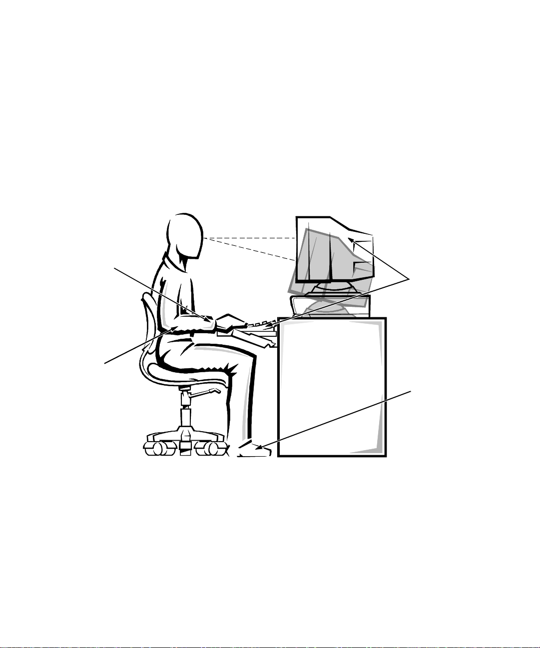
Adjust the til t of the monitor, its contrast and bright-
•
ness settings, and the lighting around you (such as
overhead light s, desk lamps, and the curta ins or
blinds on nearb y windows ) to mi nimize reflections
and glare on the monitor screen.
Use a chair that provides good lower back support.
•
Keep your forearms horizon tal with your wrists in a
•
neutral, co mfortable position while using the keyboard or mouse.
Always leave space to res t your hands while using
•
the keyboard or mouse.
wrists relaxed and flat
Let your upper arms hang naturally at your sides.
•
Sit erect, with your feet resting on the floo r and your
•
thighs level.
When sitting, make sure the weight of your legs is on
•
your feet and not on the front of your chair s eat.
Adjust your chair’ s height or use a footrest, if necessary, to maintain proper posture.
Vary your work acti vities. Try to organize your
•
work so that you do not have to type for ex tended
periods of time. When you stop typing, try to do
things that use both hands.
monit or screen at or belo w eye level
monit or and keyb oard
posit ioned directly
in front of user
arms at desk level
vi
feet flat on the floor
Page 5

W
hen Working Inside Your Computer
Before you remove the compute r cover, perform the following steps in the sequence indicated:
CAUTIONS: Do not attempt to service the
computer system yourself, except as explained in
this guide and elsewhere in Dell documentation.
Always follow installation and servicing
instru c t io n s cl o s el y.
To help avoid p ossible damage to the system board,
wait five seconds after turning off the system
before removing a component from the system
board or disconnecting a peripheral device from
the comp u ter.
1. Turn off your computer and any peripheral s.
2. Disconnect your computer and peripherals from
their power sources. Also disconnect any telephone or telecommunication lines from the computer.
Doing so reduces the po tential for personal injury or
shock.
3. Touch an unpainted m e tal s urface on the cha ssis,
such as the metal around the card-slot openings at
the back of the computer, before touching anything inside your computer.
While you work, periodically touch an unpainted
metal s u rfa c e on th e co mp u ter chassis to dis si p ate
any static ele ctricity tha t mi ght harm internal
components.
In addition, ta ke note of these safety guidelines when
appropriate:
When you disconnect a cable, pull on its connector
•
or on its strain-relief loop, not on the cable itself.
Some cables have a connector with locking tabs; if
you are disconnecting this type of cable, press in on
the locking tabs before disconnecting the cable. As
you pull connectors apart, keep them evenly aligned
to avoid bending an y connector pins. Also, before
you connect a cable, make sure both connectors are
correctly oriented and aligned.
Handle components and cards with care. Don’t
•
touch the components or contacts on a card. Hold a
card by its edges or by its metal mounting bracke t.
Hold a comp o n ent such as a microprocessor chip by
its edges, not by its pins.
Protecting Against Electrostatic Discharge
Static electricity can harm delicate components inside
your computer. T o prevent static damage , discharge
static electricity from your body before you touch any of
your computer’ s electronic components , such as the
microprocessor. You can do so by touc hing an unpain ted
metal surface on the computer chassis.
As you continue to work inside the computer, periodically touch an unpainted metal surface to remove any
static charge your body may have accumulated.
In addition to the preceding precautions, you can also
take the followin g steps to prevent damage from electrostatic discharge (ESD):
When unpacking a stati c-sensitive component from
•
its shipping carton, do not remove the component’s
antistatic packing material until you are ready to
install the component in your computer. Just before
unwrapping the antistatic packaging, be sure to discharge static el ec tricity from your body.
When transportin g a sens itive compone nt, firs t place
•
it in an an ti s t at ic contai n er or packag in g .
Handle all sensi tive c omponen ts in a sta tic-s afe ar ea.
•
If possible, use antistatic floor pads and workbench
pads.
The following caution may appear throughout this document to remind you of these precautions:
CAUTION: See “Protecting Against Electrostatic
Discharge” in the safety instructions at the front of
this guide.
vii
Page 6

viii
Page 7

Preface
A
bout This Guide
This guide is int ended for anyone who uses a Dell OptiPlex GX
first-time and expe rienced computer users who want to
learn about the f ea tures and operation of the systems or
who want to upgrade their computers. The chapters and
append i xe s ar e s u mmarized as f o ll ows:
Everyone should rea d Chapter 1, “Introduct ion,” for
•
an overview of the system features, a description of
the controls and indicators on the front panel, and a
general discussion of connecting external devices to
the back panel o f the compu t er.
Everyone should read the first few sections of Chap-
•
ter 2, “Using the Software Support Uti lities,” to find
out whic h Dell utilities and bus-mast er ing integrated
drive electr onics (IDE) drivers have been included
with the system. Only users who want to use one of
the utili ti es or bu s-ma ste ring drive rs need to read th e
rest of Chapter 2.
Everyone should rea d the first several sect ions of
•
Chapter 3 , “Using th e System Setup Program,” to
familiarize themselves with this important program.
Only users who want to make configurat ion changes
to their s ystem or who want to use the pass word features need to read the rest of Chapter 3.
Users who add or re move an Industry-S tandard Archite c-
•
ture (ISA) expansion card s hould read Chapter 4, “Using
the ISA Configuration Utili ty.”
Users who want to con nec t th eir syst em to a net work
•
should read Chapte r 5, “Using t he Networ k Inte rfa ce
Controller.” This chapter provides information on
connecting the system to a network, con f iguring the
network interface control ler (NIC), i nstalli ng driv ers
for the NIC, and running the NIC diagnostics.
computer system. It can be used by both
pro
Users who need information on the integrated sound
•
featu re s of th e co mputer s y ste m sh o ul d re ad Chap ter 6, “Using the Integr ated Audio Controller.”
Chapter 6 provide s information on connec ting audio
equipment to y our computer , in stalli ng audio dr ivers,
and reco n f ig uring the in tegrated audio controller.
Chapter 7, “Working Inside Your Computer,” Chap-
•
ter 8, “Installing System Board Options,” and
Chapter 9, “Insta ll ing Drive s,” are i nte nded for user s
who want to install or remove options inside the
computer, such as dual in-line memory modules
(DIMMs), expansion cards, or dri ves.
Appendix A, “Technical S pecifications,” and
•
Appendix B, “Hardware Configuration Features,”
are intended prima rily as refe rence ma teria l for users
interested in learning more about the details of the
system. User s who add internal options may need t o
refer to Appendix B to change jumper or switch
settings.
Appendix C, “ISA Configurat ion Utilit y Messag es,”
•
describes error messages generated by the ISA Configuration Utili ty (ICU), possible causes, and
correc tive actio n s.
Appendix D, “Maintaining the System,” describes
•
preventive maint enance procedures that you s hould
perform regularl y to kee p your computer system in
top operating condition.
Appendix E, “Regulatory Notices,” is for users who
•
are interested in which regulatory agencies have
tested and approved the Dell OptiPlex GX
systems.
Appendix F, “Warranties and Return Policy,”
•
describes the warranty for your Dell system and the
“Total Satisfaction” Return Policy.
pro
ix
Page 8

The Glossary provides definitions of terms, acro-
•
nyms, and abbreviations used in this gui de.
W
arranty and Return Policy
Information
Dell Computer Corporation (“Dell”) manufactures its
hardware products from parts and components that are
new or equivalent to new in accordance with industrystandard pract ices. For information about the Dell
warranty for your system, se e Appe ndix F, “W arranties
and Return Poli cy. ”
O
ther Documents You May Need
Besides this
included with your system:
The
•
instructions for setting up your compute r system.
The
•
detailed answers to questions that ar e often asked b y
Dell com pu t er users. Be sur e to r ead th e se cards
before calling Dell for techni ca l ass is tance.
The
•
includes trouble shooting proc edures and inst ructions
for using the diskette-based diagnostics
computer system.
The
•
instructions for using the application programs that
take advantage of the computer’s integrated sound
feature. These programs ar e installed on your harddisk drive.
Video card documentation from the card manufac-
•
turer describes the video drivers included with the
system. Only users who want to use or change a
video driver need to read this documentat ion in
detail.
You may also have one or more of the following
documents.
NOTE: Documentation upda tes are someti mes included
with your syst em to describe changes to your system or
software. Always read these up dates
User’ s Guide
Getting Started
Fre quently Asked Questions
Diagnostics and Troubleshooting Guide
Dell Integrated A udio User’s Guide
, the following doc umentat ion is
sheet pr ovi d es st ep - b y-step
card s pr o vide
to test your
prov i des
before
consulting any
other documentation because the updates often contain the latest information.
Operating system documentation is included if you
•
ordered your operating system software from Dell.
This documentation describes how to instal l (if necessary), configure, and us e your operating system
software.
Documentation is included with any options you
•
purchase separately from your system. This documentation includes information that you nee d to
configure and install these options in your Dell computer. Installatio n instructions for the options are
included in this
Technical information files—so metimes called
•
“readme” files—may be ins talled on your hard-disk
drive to provide last-minute updates about technical
changes to your system or advanced technical reference material intended for experienced users or
technicians.
N
otational Conventions
The following subsections list notational conventions
used in this document.
Use r’s Gui de
.
Warnings, Cautions, and Notes
Throughout this guide, there may be blocks of text
printed in bold type within boxes or in italic type. These
blocks are warnings, cautions, and notes, and they are
used as follows:
WARNING: A WARNING indicates the potential
for bodily harm and tells you how to avoid the
problem.
CAUTION: A CAUTION indicates either potential damage to hardware or los s of data and tells
you how to avoid the problem.
NOTE: A NOTE indicates important info rmation that
helps you make better use of your computer system.
x
Page 9

Typographical Conventions
The following list defines (where appropriate) and illustrates typo graphical conventions used as visual cues for
specific elements of text throughout this document:
•
Keycaps
keyboard, a re pre sent ed i n up percase a nd enc losed in
angle brackets .
Example : <
•
Key combinations
simultaneo usl y (unless otherwise in dicated) to perform a single function.
Example : <
All
•
VETICA
Example :
•
Commands
ence purposes only and are not intended to be typed
at that parti cular point in the discussion.
Example: “Use the
In contrast, comma nds presented in the Courier
font are intend ed to be typed a s part of an instruct ion.
Example: “Type format a: to format the diskette in
drive A.”
•
Filenames
lowercase bold.
Examples:
, the labeli ng that appears on the keys on a
>
ENTER
are series of keys to be pressed
CTRL><ALT><ENTER
items on a menu screen
font and in uppercase bold.
SETUP PASSWORD
presented in l owercase bold are for re fer-
format
and
directory names
autoexec.bat
>
are prese nted in the
category
command t o . . . .”
are prese nt ed in
c:\windows
and
HEL-
•
Syntax lines
possible paramet ers. Commands are displayed in
lowercase bold; variable parameter s (those for which
you substitute a value) are displayed in lowercase
italics; constant parameters are displayed in lowercase bold. The brac k ets indicate items that are
optional.
Example:
•
Command lines
include one or more of the command’s possible
parameters. Command li nes are presented in the
Courier font.
Example:
•
Screen text
monitor or display. It can be a system message, for
example, or it can be text that you are instructed to
type as part of a command (referred to as a
line)
Example: “Type md c:\dos, and then press
<
ENTER
Example: The following messa ge appears on your
screen:
No boot devic e available
•
Variables
value. They ar e pr esented in it al i cs.
Example: DIMM n (where n represen ts the DIMM
socket designation)
consist of a command and all its
del
del c:\myfile.doc
is text that appears on the screen of your
. Screen text is presented in the Courier font.
>.”
are placeholder s f or which y ou subs titut e a
:
[
] [
drive
path]filename
consist of a comman d and may
[/p]
command
xi
Page 10

xii
Page 11

Contents
Chapter 1
Introduction . . . . . . . . . . . . . . . . . . . . . . . . . . . . . . . . . . . . . . . . . . . 1-1
System Features. . . . . . . . . . . . . . . . . . . . . . . . . . . . . . . . . . . . . . . . . . . . . . . . . . . . . . 1-1
Important Note to Windows 95 User s. . . . . . . . . . . . . . . . . . . . . . . . . . . . . . . . . . . . . 1-3
Using the Floor Stand . . . . . . . . . . . . . . . . . . . . . . . . . . . . . . . . . . . . . . . . . . . . . . . . . 1-3
Front Panel . . . . . . . . . . . . . . . . . . . . . . . . . . . . . . . . . . . . . . . . . . . . . . . . . . . . . . . . . 1-4
Back Panel. . . . . . . . . . . . . . . . . . . . . . . . . . . . . . . . . . . . . . . . . . . . . . . . . . . . . . . . . . 1-5
Connecting External Devices. . . . . . . . . . . . . . . . . . . . . . . . . . . . . . . . . . . . . . . . 1-5
Security Cable Slot. . . . . . . . . . . . . . . . . . . . . . . . . . . . . . . . . . . . . . . . . . . . . . . . 1-5
Getting Help . . . . . . . . . . . . . . . . . . . . . . . . . . . . . . . . . . . . . . . . . . . . . . . . . . . . . . . . 1-6
Chapter 2
Using the Software Support Utilities . . . . . . . . . . . . . . . . . . . . . . . 2-1
Software Support Utilities on Diskette . . . . . . . . . . . . . . . . . . . . . . . . . . . . . . . . . . . . 2-1
Dell-Installed Software Support Uti lities . . . . . . . . . . . . . . . . . . . . . . . . . . . . . . . . . . 2-1
Backing Up the Software Support Utilities. . . . . . . . . . . . . . . . . . . . . . . . . . . . . . . . . 2-2
System Utilities and Services . . . . . . . . . . . . . . . . . . . . . . . . . . . . . . . . . . . . . . . . . . . 2-2
Asset Tag Utility . . . . . . . . . . . . . . . . . . . . . . . . . . . . . . . . . . . . . . . . . . . . . . . . . 2-2
Installing the Asset Tag Utility. . . . . . . . . . . . . . . . . . . . . . . . . . . . . . . . . . . 2-2
Using the Asset Tag Utility. . . . . . . . . . . . . . . . . . . . . . . . . . . . . . . . . . . . . . 2-2
Auto Power On Utility . . . . . . . . . . . . . . . . . . . . . . . . . . . . . . . . . . . . . . . . . . . . . 2-3
Installing the Auto Power On Utility . . . . . . . . . . . . . . . . . . . . . . . . . . . . . . 2-3
Dell AutoShutdown Service. . . . . . . . . . . . . . . . . . . . . . . . . . . . . . . . . . . . . . . . . 2-3
How AutoShutdown Works . . . . . . . . . . . . . . . . . . . . . . . . . . . . . . . . . . . . . 2-3
If Your Operating System Locks Up . . . . . . . . . . . . . . . . . . . . . . . . . . . . . . 2-4
Dell Thermal Shutdown Service . . . . . . . . . . . . . . . . . . . . . . . . . . . . . . . . . . . . . 2-4
How Thermal Shutdown Works . . . . . . . . . . . . . . . . . . . . . . . . . . . . . . . . . . 2-4
Installing the Dell AutoShutdown and Thermal Shutdown Services. . . . . . . . . . 2-4
Removing a Service . . . . . . . . . . . . . . . . . . . . . . . . . . . . . . . . . . . . . . . . . . . 2-4
xiii
Page 12

Dell Energy Manager . . . . . . . . . . . . . . . . . . . . . . . . . . . . . . . . . . . . . . . . . . . . . . . . . 2-5
Installing the Dell Energy Manager . . . . . . . . . . . . . . . . . . . . . . . . . . . . . . . . . . 2-5
Bus-Mastering IDE Drivers . . . . . . . . . . . . . . . . . . . . . . . . . . . . . . . . . . . . . . . . . . . . 2-5
Windows NT 3.5x. . . . . . . . . . . . . . . . . . . . . . . . . . . . . . . . . . . . . . . . . . . . . . . . 2-5
OS/2. . . . . . . . . . . . . . . . . . . . . . . . . . . . . . . . . . . . . . . . . . . . . . . . . . . . . . . . . . . 2-6
Chapter 3
Using the System Setup Program . . . . . . . . . . . . . . . . . . . . . . . . . 3-1
Entering the System Setup Program. . . . . . . . . . . . . . . . . . . . . . . . . . . . . . . . . . . . . . 3-1
System Setup Screens. . . . . . . . . . . . . . . . . . . . . . . . . . . . . . . . . . . . . . . . . . . . . . . . . 3-2
Using the System Setup Program. . . . . . . . . . . . . . . . . . . . . . . . . . . . . . . . . . . . . . . . 3-2
System Setup Categories . . . . . . . . . . . . . . . . . . . . . . . . . . . . . . . . . . . . . . . . . . . . . . 3-4
Time . . . . . . . . . . . . . . . . . . . . . . . . . . . . . . . . . . . . . . . . . . . . . . . . . . . . . . . . . . 3-4
Date . . . . . . . . . . . . . . . . . . . . . . . . . . . . . . . . . . . . . . . . . . . . . . . . . . . . . . . . . . . 3-4
Diskette Drive A and Diskette Drive B. . . . . . . . . . . . . . . . . . . . . . . . . . . . . . . . 3-4
Drive A Location. . . . . . . . . . . . . . . . . . . . . . . . . . . . . . . . . . . . . . . . . . . . . . . . . 3-4
Drives: Primary and Secondary. . . . . . . . . . . . . . . . . . . . . . . . . . . . . . . . . . . . . . 3-4
EIDE Devices Other Than Hard-Disk Drives . . . . . . . . . . . . . . . . . . . . . . . 3-5
EIDE Hard-Disk Drives . . . . . . . . . . . . . . . . . . . . . . . . . . . . . . . . . . . . . . . . 3-5
If You Have a Problem . . . . . . . . . . . . . . . . . . . . . . . . . . . . . . . . . . . . . . . . 3-5
Base Memory . . . . . . . . . . . . . . . . . . . . . . . . . . . . . . . . . . . . . . . . . . . . . . . . . . . 3-5
Extended Memory. . . . . . . . . . . . . . . . . . . . . . . . . . . . . . . . . . . . . . . . . . . . . . . . 3-6
Reserved Memory . . . . . . . . . . . . . . . . . . . . . . . . . . . . . . . . . . . . . . . . . . . . . . . . 3-6
Fast Video BIOS . . . . . . . . . . . . . . . . . . . . . . . . . . . . . . . . . . . . . . . . . . . . . . . . . 3-6
CPU Speed . . . . . . . . . . . . . . . . . . . . . . . . . . . . . . . . . . . . . . . . . . . . . . . . . . . . . 3-6
Num Lock . . . . . . . . . . . . . . . . . . . . . . . . . . . . . . . . . . . . . . . . . . . . . . . . . . . . . . 3-6
Keyboard Errors . . . . . . . . . . . . . . . . . . . . . . . . . . . . . . . . . . . . . . . . . . . . . . . . . 3-6
System Password. . . . . . . . . . . . . . . . . . . . . . . . . . . . . . . . . . . . . . . . . . . . . . . . . 3-7
Password Status. . . . . . . . . . . . . . . . . . . . . . . . . . . . . . . . . . . . . . . . . . . . . . . . . . 3-7
Boot Sequence. . . . . . . . . . . . . . . . . . . . . . . . . . . . . . . . . . . . . . . . . . . . . . . . . . . 3-7
Setup Password . . . . . . . . . . . . . . . . . . . . . . . . . . . . . . . . . . . . . . . . . . . . . . . . . . 3-7
Auto Power On . . . . . . . . . . . . . . . . . . . . . . . . . . . . . . . . . . . . . . . . . . . . . . . . . . 3-8
Power Management. . . . . . . . . . . . . . . . . . . . . . . . . . . . . . . . . . . . . . . . . . . . . . . 3-8
Saving Monitor Power . . . . . . . . . . . . . . . . . . . . . . . . . . . . . . . . . . . . . . . . . 3-8
Saving EIDE Hard-Disk Drive Power . . . . . . . . . . . . . . . . . . . . . . . . . . . . . 3-8
Sound. . . . . . . . . . . . . . . . . . . . . . . . . . . . . . . . . . . . . . . . . . . . . . . . . . . . . . . . . . 3-9
NIC . . . . . . . . . . . . . . . . . . . . . . . . . . . . . . . . . . . . . . . . . . . . . . . . . . . . . . . . . . . 3-9
Mouse . . . . . . . . . . . . . . . . . . . . . . . . . . . . . . . . . . . . . . . . . . . . . . . . . . . . . . . . . 3-9
Serial Port 1 and Serial Port 2 . . . . . . . . . . . . . . . . . . . . . . . . . . . . . . . . . . . . . . . 3-9
xiv
Page 13

Parallel Port . . . . . . . . . . . . . . . . . . . . . . . . . . . . . . . . . . . . . . . . . . . . . . . . . . . . . 3-9
Parallel Mode . . . . . . . . . . . . . . . . . . . . . . . . . . . . . . . . . . . . . . . . . . . . . . . . . . . . 3-9
IDE Hard Disk . . . . . . . . . . . . . . . . . . . . . . . . . . . . . . . . . . . . . . . . . . . . . . . . . . 3-10
Diskette . . . . . . . . . . . . . . . . . . . . . . . . . . . . . . . . . . . . . . . . . . . . . . . . . . . . . . . 3-10
Speaker. . . . . . . . . . . . . . . . . . . . . . . . . . . . . . . . . . . . . . . . . . . . . . . . . . . . . . . . 3-10
System Data Categories . . . . . . . . . . . . . . . . . . . . . . . . . . . . . . . . . . . . . . . . . . . 3-10
Using the System Password Feature . . . . . . . . . . . . . . . . . . . . . . . . . . . . . . . . . . . . . 3-10
Assigning a System Password . . . . . . . . . . . . . . . . . . . . . . . . . . . . . . . . . . . . . . 3-11
Using Your System Password to Secure Your System . . . . . . . . . . . . . . . . . . . 3-12
Deleting or Changing an Existing System Password. . . . . . . . . . . . . . . . . . . . . 3-12
Using the Setup Password Feature . . . . . . . . . . . . . . . . . . . . . . . . . . . . . . . . . . . . . . 3-13
Assigning a Setup Password . . . . . . . . . . . . . . . . . . . . . . . . . . . . . . . . . . . . . . . 3-13
Operating With a Setup Password Enabled . . . . . . . . . . . . . . . . . . . . . . . . . . . . 3-13
Deleting or Changing an Existing Setup Password . . . . . . . . . . . . . . . . . . . . . . 3-13
Disabling a Forgotten Password . . . . . . . . . . . . . . . . . . . . . . . . . . . . . . . . . . . . . . . . 3-14
Responding to Error Mess ages . . . . . . . . . . . . . . . . . . . . . . . . . . . . . . . . . . . . . . . . . 3-14
Chapter 4
Using the ISA Configuration Utility . . . . . . . . . . . . . . . . . . . . . . . . 4-1
Quick Start. . . . . . . . . . . . . . . . . . . . . . . . . . . . . . . . . . . . . . . . . . . . . . . . . . . . . . . . . . 4-1
About the ICU . . . . . . . . . . . . . . . . . . . . . . . . . . . . . . . . . . . . . . . . . . . . . . . . . . . . . . . 4-2
ISA Database . . . . . . . . . . . . . . . . . . . . . . . . . . . . . . . . . . . . . . . . . . . . . . . . . . . . 4-2
When to Run the ICU . . . . . . . . . . . . . . . . . . . . . . . . . . . . . . . . . . . . . . . . . . . . . . . . . 4-2
Preparing to Use the ICU . . . . . . . . . . . . . . . . . . . . . . . . . . . . . . . . . . . . . . . . . . . . . . 4-3
Backing Up the ISA Configuration Utility Diskette . . . . . . . . . . . . . . . . . . . . . . 4-3
Starting the ICU. . . . . . . . . . . . . . . . . . . . . . . . . . . . . . . . . . . . . . . . . . . . . . . . . . . . . . 4-3
Accessing Help. . . . . . . . . . . . . . . . . . . . . . . . . . . . . . . . . . . . . . . . . . . . . . . . . . . 4-4
Making Selections in the ICU . . . . . . . . . . . . . . . . . . . . . . . . . . . . . . . . . . . . . . . 4-4
Adding a Listed Card . . . . . . . . . . . . . . . . . . . . . . . . . . . . . . . . . . . . . . . . . . . . . . . . . 4-4
Adding an Unlisted Card. . . . . . . . . . . . . . . . . . . . . . . . . . . . . . . . . . . . . . . . . . . . . . . 4-6
Modifying a Card . . . . . . . . . . . . . . . . . . . . . . . . . . . . . . . . . . . . . . . . . . . . . . . . . . . . 4-7
Removing a Card. . . . . . . . . . . . . . . . . . . . . . . . . . . . . . . . . . . . . . . . . . . . . . . . . . . . . 4-8
Viewing Resources . . . . . . . . . . . . . . . . . . . . . . . . . . . . . . . . . . . . . . . . . . . . . . . . . . . 4-9
Saving the System Configuration . . . . . . . . . . . . . . . . . . . . . . . . . . . . . . . . . . . . . . . . 4-9
Exiting From the ICU . . . . . . . . . . . . . . . . . . . . . . . . . . . . . . . . . . . . . . . . . . . . . . . . 4-10
Advanced Features of the ICU . . . . . . . . . . . . . . . . . . . . . . . . . . . . . . . . . . . . . . . . . 4-10
Locking and Unlocking Cards . . . . . . . . . . . . . . . . . . . . . . . . . . . . . . . . . . . . . . 4-10
Locking and Unlocking All Resources . . . . . . . . . . . . . . . . . . . . . . . . . . . . 4-10
Locking and Unlocking Configuration Resources . . . . . . . . . . . . . . . . . . . 4-11
xv
Page 14

Modifying the Configuration Manager . . . . . . . . . . . . . . . . . . . . . . . . . . . . . . . 4-11
Using Image Files . . . . . . . . . . . . . . . . . . . . . . . . . . . . . . . . . . . . . . . . . . . . . . . 4-11
Loading an Image File . . . . . . . . . . . . . . . . . . . . . . . . . . . . . . . . . . . . . . . . 4-12
Saving an Image to a File. . . . . . . . . . . . . . . . . . . . . . . . . . . . . . . . . . . . . . 4-12
Chapter 5
Using the Network Interface Controller. . . . . . . . . . . . . . . . . . . . . 5-1
Connecting to a Network . . . . . . . . . . . . . . . . . . . . . . . . . . . . . . . . . . . . . . . . . . . . . . 5-1
Configuring the NIC. . . . . . . . . . . . . . . . . . . . . . . . . . . . . . . . . . . . . . . . . . . . . . . . . . 5-2
Using Install to Change Configuration Settings . . . . . . . . . . . . . . . . . . . . . . . . . 5-3
Installing Network Drivers. . . . . . . . . . . . . . . . . . . . . . . . . . . . . . . . . . . . . . . . . . . . . 5-3
NetWare Drivers and Client Software. . . . . . . . . . . . . . . . . . . . . . . . . . . 5-3
Novell
Determining an Adapter’s Port Address . . . . . . . . . . . . . . . . . . . . . . . . . . . 5-3
Client Workstation With Built-In 3Com PCI Network Adapter Only. . . . . 5-3
Client Workstation With Multiple 3Com PCI Network Adapters. . . . . . . . 5-4
Server With Built-In 3Com PCI Network Adapter Only. . . . . . . . . . . . . . . 5-4
Server With Multiple 3Com PCI Network Adapters. . . . . . . . . . . . . . . . . . 5-5
Windows NT 3.51 Drivers . . . . . . . . . . . . . . . . . . . . . . . . . . . . . . . . . . . . . . . . . 5-6
Installing Drivers During Operating System Installation . . . . . . . . . . . . . . 5-6
Installi ng Dr ivers Subsequent to Operating System Installation. . . . . . . . . 5-6
Installing Other Drivers. . . . . . . . . . . . . . . . . . . . . . . . . . . . . . . . . . . . . . . . . . . . 5-7
Running the NIC Diagnostics. . . . . . . . . . . . . . . . . . . . . . . . . . . . . . . . . . . . . . . . . . . 5-7
Running the Group 1 Tests . . . . . . . . . . . . . . . . . . . . . . . . . . . . . . . . . . . . . . . . . 5-7
Running the Group 3 Test. . . . . . . . . . . . . . . . . . . . . . . . . . . . . . . . . . . . . . . . . . 5-8
Setting Up an Echo Server. . . . . . . . . . . . . . . . . . . . . . . . . . . . . . . . . . . . . . 5-8
Running the Diagnostic Tests . . . . . . . . . . . . . . . . . . . . . . . . . . . . . . . . . . . 5-8
Changing the Test Parameters. . . . . . . . . . . . . . . . . . . . . . . . . . . . . . . . . . . . . . . 5-8
What to Do If a Test Fails. . . . . . . . . . . . . . . . . . . . . . . . . . . . . . . . . . . . . . . . . . 5-9
Chapter 6
Using the Integrated Audio Controller. . . . . . . . . . . . . . . . . . . . . . 6-1
Using System Software . . . . . . . . . . . . . . . . . . . . . . . . . . . . . . . . . . . . . . . . . . . . . . . 6-1
Reverting to an Earlier BIOS Version. . . . . . . . . . . . . . . . . . . . . . . . . . . . . . . . . 6-1
Connecting Audi o Devices. . . . . . . . . . . . . . . . . . . . . . . . . . . . . . . . . . . . . . . . . . . . . 6-2
Speakers . . . . . . . . . . . . . . . . . . . . . . . . . . . . . . . . . . . . . . . . . . . . . . . . . . . . . . . 6-2
Microphones . . . . . . . . . . . . . . . . . . . . . . . . . . . . . . . . . . . . . . . . . . . . . . . . . . . . 6-2
Record/Playback Devices . . . . . . . . . . . . . . . . . . . . . . . . . . . . . . . . . . . . . . . . . . 6-2
CD-ROM Drives . . . . . . . . . . . . . . . . . . . . . . . . . . . . . . . . . . . . . . . . . . . . . . . . . 6-2
xvi
Page 15

Adjusting Volume . . . . . . . . . . . . . . . . . . . . . . . . . . . . . . . . . . . . . . . . . . . . . . . . . . . . 6-3
Adjusting Volume in Microsoft Windows NT 4.0 and Windows 95 . . . . . . . . . 6-3
Adjusting Volume in Microsoft Windows NT 3.51. . . . . . . . . . . . . . . . . . . . . . . 6-3
Adjusting Volume in Microsoft Windows. . . . . . . . . . . . . . . . . . . . . . . . . . . . . . 6-3
Adjusting Volume in MS-DOS . . . . . . . . . . . . . . . . . . . . . . . . . . . . . . . . . . . . . . 6-3
Using the Dell-Installed Audio Application Programs . . . . . . . . . . . . . . . . . . . . . . . . 6-4
Configuring the Integrated Audio Controller . . . . . . . . . . . . . . . . . . . . . . . . . . . . . . . 6-4
Installing Audio Drivers . . . . . . . . . . . . . . . . . . . . . . . . . . . . . . . . . . . . . . . . . . . . . . . 6-5
MS-DOS, Windows 3.1x, and Windows for Workgroups. . . . . . . . . . . . . . . . . . 6-6
Windows NT 3.51 and 4.0 . . . . . . . . . . . . . . . . . . . . . . . . . . . . . . . . . . . . . . . . . . 6-6
Chapter 7
Working Inside Your Computer . . . . . . . . . . . . . . . . . . . . . . . . . . . 7-1
Before You Begin . . . . . . . . . . . . . . . . . . . . . . . . . . . . . . . . . . . . . . . . . . . . . . . . . . . . 7-1
Safety First—For You and Your Computer. . . . . . . . . . . . . . . . . . . . . . . . . . . . . 7-1
Removing the Computer Cover . . . . . . . . . . . . . . . . . . . . . . . . . . . . . . . . . . . . . . 7-2
Replacing the Computer Cover . . . . . . . . . . . . . . . . . . . . . . . . . . . . . . . . . . . . . . 7-2
Unpacking Your Hardware Option . . . . . . . . . . . . . . . . . . . . . . . . . . . . . . . . . . . 7-3
Inside Your Computer. . . . . . . . . . . . . . . . . . . . . . . . . . . . . . . . . . . . . . . . . . . . . . . . . 7-3
Removing and Replacing the Expansion-Card Cage . . . . . . . . . . . . . . . . . . . . . . . . . 7-5
Removing the Expansion-Card Cage . . . . . . . . . . . . . . . . . . . . . . . . . . . . . . . . . . 7-5
Replacing the Expansion-Card Cage . . . . . . . . . . . . . . . . . . . . . . . . . . . . . . . . . . 7-5
Rotating the Power Supply Away From the System Board . . . . . . . . . . . . . . . . . . . . 7-6
Chapter 8
Installing System Board Options . . . . . . . . . . . . . . . . . . . . . . . . . . 8-1
Expansion Cards . . . . . . . . . . . . . . . . . . . . . . . . . . . . . . . . . . . . . . . . . . . . . . . . . . . . . 8-2
Expansion Slots . . . . . . . . . . . . . . . . . . . . . . . . . . . . . . . . . . . . . . . . . . . . . . . . . . 8-2
Installing an Expansion Card . . . . . . . . . . . . . . . . . . . . . . . . . . . . . . . . . . . . . . . . 8-3
Removing an Expansion Card . . . . . . . . . . . . . . . . . . . . . . . . . . . . . . . . . . . . . . . 8-4
Adding Memory . . . . . . . . . . . . . . . . . . . . . . . . . . . . . . . . . . . . . . . . . . . . . . . . . . . . . 8-4
DIMM Installation Guidelines . . . . . . . . . . . . . . . . . . . . . . . . . . . . . . . . . . . . . . . 8-4
Performing a Memory Upgrade . . . . . . . . . . . . . . . . . . . . . . . . . . . . . . . . . . . . . . 8-5
Installing a DIMM . . . . . . . . . . . . . . . . . . . . . . . . . . . . . . . . . . . . . . . . . . . . 8-6
Removing a DIMM. . . . . . . . . . . . . . . . . . . . . . . . . . . . . . . . . . . . . . . . . . . . 8-6
Microprocessor Upgrades . . . . . . . . . . . . . . . . . . . . . . . . . . . . . . . . . . . . . . . . . . . . . . 8-6
Upgrading the System Board Microprocessor. . . . . . . . . . . . . . . . . . . . . . . . . . . 8-7
xvii
Page 16

Adding a Secondary Micr oprocessor . . . . . . . . . . . . . . . . . . . . . . . . . . . . . . . . 8-11
Installing the Microprocessor Add-In Card . . . . . . . . . . . . . . . . . . . . . . . . 8-11
Upgrading the Secondary Microprocessor . . . . . . . . . . . . . . . . . . . . . . . . . . . . 8-12
Replacing the System Battery . . . . . . . . . . . . . . . . . . . . . . . . . . . . . . . . . . . . . . . . . 8-13
Chapter 9
Installing Drives. . . . . . . . . . . . . . . . . . . . . . . . . . . . . . . . . . . . . . . . 9-1
Determining the Boot Diskette Drive. . . . . . . . . . . . . . . . . . . . . . . . . . . . . . . . . . . . . 9-1
Configuring Your Drive . . . . . . . . . . . . . . . . . . . . . . . . . . . . . . . . . . . . . . . . . . . . . . . 9-2
Jumpers and Switches . . . . . . . . . . . . . . . . . . . . . . . . . . . . . . . . . . . . . . . . . . . . . 9-2
Removing and Replacing Front-Panel Inserts . . . . . . . . . . . . . . . . . . . . . . . . . . . . . . 9-2
Connecting Driv es . . . . . . . . . . . . . . . . . . . . . . . . . . . . . . . . . . . . . . . . . . . . . . . . . . . 9-3
Installing Drives in the Drive Cage . . . . . . . . . . . . . . . . . . . . . . . . . . . . . . . . . . . . . . 9-3
Installing a Drive That Uses a Built-In Drive Interface in a
5.25-Inch Drive Bay . . . . . . . . . . . . . . . . . . . . . . . . . . . . . . . . . . . . . . . . . . . . . . 9-3
Installing a Diskette Drive on the 3.5-Inch Bracket . . . . . . . . . . . . . . . . . . . . . . 9-6
Installing an Internal Tape Drive or CD-ROM Drive
That Uses a Controller Card . . . . . . . . . . . . . . . . . . . . . . . . . . . . . . . . . . . . . . . . 9-7
Installing an External Tape Drive. . . . . . . . . . . . . . . . . . . . . . . . . . . . . . . . . . . . . . . . 9-8
Installing an EIDE Hard-Disk Drive . . . . . . . . . . . . . . . . . . . . . . . . . . . . . . . . . . . . . 9-9
EIDE Drive Addressing . . . . . . . . . . . . . . . . . . . . . . . . . . . . . . . . . . . . . . . . . . . 9-9
Installing an EIDE Hard-Di sk Drive in the Hard-Disk Drive Bracket . . . 9-10
Partitio ning and Logically Formatting Your EIDE Hard-Disk Drive. . . . . . . . 9-12
Installing SCSI Devices . . . . . . . . . . . . . . . . . . . . . . . . . . . . . . . . . . . . . . . . . . . . . . 9-12
SCSI Configuration Guidelines. . . . . . . . . . . . . . . . . . . . . . . . . . . . . . . . . . . . . 9-12
SCSI ID Numbers . . . . . . . . . . . . . . . . . . . . . . . . . . . . . . . . . . . . . . . . . . . 9-12
SCSI Cable and SCSI Terminators . . . . . . . . . . . . . . . . . . . . . . . . . . . . . . 9-13
General Procedure for Installing SCSI Devices . . . . . . . . . . . . . . . . . . . . . . . . 9-14
Partitioning and Formatting SCSI Hard-Disk Drives . . . . . . . . . . . . . . . . . . . . 9-15
Appendix A
Technical Specifications. . . . . . . . . . . . . . . . . . . . . . . . . . . . . . . . . A-1
xviii
Page 17

Appendix B
Hardware Configuration Features . . . . . . . . . . . . . . . . . . . . . . . . . B-1
Jumpers and Switches—A General Explanation. . . . . . . . . . . . . . . . . . . . . . . . . . . . .B-1
Jumpers . . . . . . . . . . . . . . . . . . . . . . . . . . . . . . . . . . . . . . . . . . . . . . . . . . . . . . . .B-1
Switches . . . . . . . . . . . . . . . . . . . . . . . . . . . . . . . . . . . . . . . . . . . . . . . . . . . . . . . .B-1
System Board Labels. . . . . . . . . . . . . . . . . . . . . . . . . . . . . . . . . . . . . . . . . . . . . . . . . .B-3
I/O Ports and Connectors . . . . . . . . . . . . . . . . . . . . . . . . . . . . . . . . . . . . . . . . . . . . . .B-5
Serial and Parallel Ports . . . . . . . . . . . . . . . . . . . . . . . . . . . . . . . . . . . . . . . . . . . .B-5
Adding an Expansion Ca rd Containing Serial or Parallel Ports. . . . . . . . . .B-5
Serial Port Connectors . . . . . . . . . . . . . . . . . . . . . . . . . . . . . . . . . . . . . . . . .B-6
Parallel Port Connector . . . . . . . . . . . . . . . . . . . . . . . . . . . . . . . . . . . . . . . . .B-6
Keyboard and Mouse Connect ors . . . . . . . . . . . . . . . . . . . . . . . . . . . . . . . . . . . .B-7
Keyboard Connector. . . . . . . . . . . . . . . . . . . . . . . . . . . . . . . . . . . . . . . . . . .B-7
Mouse Connector . . . . . . . . . . . . . . . . . . . . . . . . . . . . . . . . . . . . . . . . . . . . .B-8
Video Connector . . . . . . . . . . . . . . . . . . . . . . . . . . . . . . . . . . . . . . . . . . . . . . . . .B-8
Interrupt Assignments . . . . . . . . . . . . . . . . . . . . . . . . . . . . . . . . . . . . . . . . . . . . . . . . .B-8
Memory Allocations . . . . . . . . . . . . . . . . . . . . . . . . . . . . . . . . . . . . . . . . . . . . . . . . . .B-9
Appendix C
Beep Codes and System Messages. . . . . . . . . . . . . . . . . . . . . . . . C-1
New Diagnostics Test . . . . . . . . . . . . . . . . . . . . . . . . . . . . . . . . . . . . . . . . . . . . . . . . .C-1
Beep Code Update. . . . . . . . . . . . . . . . . . . . . . . . . . . . . . . . . . . . . . . . . . . . . . . . . . . .C-1
Additional System Error Messages . . . . . . . . . . . . . . . . . . . . . . . . . . . . . . . . . . . . . . .C-1
ISA Configuration Utility Messages . . . . . . . . . . . . . . . . . . . . . . . . . . . . . . . . . . . . . .C-3
ICU Error Messages. . . . . . . . . . . . . . . . . . . . . . . . . . . . . . . . . . . . . . . . . . . . . . .C-3
Configuration Manager Messages . . . . . . . . . . . . . . . . . . . . . . . . . . . . . . . . . . . .C-9
Appendix D
Maintaining the System. . . . . . . . . . . . . . . . . . . . . . . . . . . . . . . . . . D-1
Data Preservation . . . . . . . . . . . . . . . . . . . . . . . . . . . . . . . . . . . . . . . . . . . . . . . . . . . .D-1
Scheduling Bac kups. . . . . . . . . . . . . . . . . . . . . . . . . . . . . . . . . . . . . . . . . . . . . . .D-1
Backup Devices . . . . . . . . . . . . . . . . . . . . . . . . . . . . . . . . . . . . . . . . . . . . . . . . . .D-1
Recovering Data. . . . . . . . . . . . . . . . . . . . . . . . . . . . . . . . . . . . . . . . . . . . . . . . . .D-1
Cleaning System Components. . . . . . . . . . . . . . . . . . . . . . . . . . . . . . . . . . . . . . . . . . .D-2
Recommended Tools and Accessories. . . . . . . . . . . . . . . . . . . . . . . . . . . . . . . . .D-2
Cleaning the Computer, Monitor, and Keyboard Exteriors . . . . . . . . . . . . . . . . .D-2
Cleaning Drives . . . . . . . . . . . . . . . . . . . . . . . . . . . . . . . . . . . . . . . . . . . . . . . . . .D-3
xix
Page 18

Environmental Factors . . . . . . . . . . . . . . . . . . . . . . . . . . . . . . . . . . . . . . . . . . . . . . . . D-3
Temperature . . . . . . . . . . . . . . . . . . . . . . . . . . . . . . . . . . . . . . . . . . . . . . . . . . . . D-3
Humidity . . . . . . . . . . . . . . . . . . . . . . . . . . . . . . . . . . . . . . . . . . . . . . . . . . . . . . . D-3
Altitude . . . . . . . . . . . . . . . . . . . . . . . . . . . . . . . . . . . . . . . . . . . . . . . . . . . . . . . . D-3
Dust and Particles . . . . . . . . . . . . . . . . . . . . . . . . . . . . . . . . . . . . . . . . . . . . . . . . D-4
Corrosion. . . . . . . . . . . . . . . . . . . . . . . . . . . . . . . . . . . . . . . . . . . . . . . . . . . . . . . D-4
ESD . . . . . . . . . . . . . . . . . . . . . . . . . . . . . . . . . . . . . . . . . . . . . . . . . . . . . . . . . . . D-4
Electromagnetic and Radio Frequency Interference . . . . . . . . . . . . . . . . . . . . . . D-4
Magnetism. . . . . . . . . . . . . . . . . . . . . . . . . . . . . . . . . . . . . . . . . . . . . . . . . . . . . . D-5
Shock and Vibration . . . . . . . . . . . . . . . . . . . . . . . . . . . . . . . . . . . . . . . . . . . . . . D-5
Power Source Interruptions. . . . . . . . . . . . . . . . . . . . . . . . . . . . . . . . . . . . . . . . . D-5
Power Protection Devices. . . . . . . . . . . . . . . . . . . . . . . . . . . . . . . . . . . . . . . . . . . . . . D-6
Surge Protectors . . . . . . . . . . . . . . . . . . . . . . . . . . . . . . . . . . . . . . . . . . . . . . . . . D-6
Line Conditi oners . . . . . . . . . . . . . . . . . . . . . . . . . . . . . . . . . . . . . . . . . . . . . . . . D-6
Uninterruptible Power Supply. . . . . . . . . . . . . . . . . . . . . . . . . . . . . . . . . . . . . . . D-6
Appendix E
Regulatory Notices . . . . . . . . . . . . . . . . . . . . . . . . . . . . . . . . . . . . . E-1
FCC Notices (U.S. Only) . . . . . . . . . . . . . . . . . . . . . . . . . . . . . . . . . . . . . . . . . . . . . . E-1
Class A . . . . . . . . . . . . . . . . . . . . . . . . . . . . . . . . . . . . . . . . . . . . . . . . . . . . . . . . E-1
Class B. . . . . . . . . . . . . . . . . . . . . . . . . . . . . . . . . . . . . . . . . . . . . . . . . . . . . . . . . E-1
IC Notice (Canada Only) . . . . . . . . . . . . . . . . . . . . . . . . . . . . . . . . . . . . . . . . . . . . . . E-2
EN 55022 Complian ce (Czech Republic Only). . . . . . . . . . . . . . . . . . . . . . . . . . . . . E-2
CE Notice . . . . . . . . . . . . . . . . . . . . . . . . . . . . . . . . . . . . . . . . . . . . . . . . . . . . . . . . . . E-3
VCCI Notices (Japan Only) . . . . . . . . . . . . . . . . . . . . . . . . . . . . . . . . . . . . . . . . . . . . E-3
Class 1 Notice . . . . . . . . . . . . . . . . . . . . . . . . . . . . . . . . . . . . . . . . . . . . . . . . . . . E-3
Class 2 Notice . . . . . . . . . . . . . . . . . . . . . . . . . . . . . . . . . . . . . . . . . . . . . . . . . . . E-3
Korean Regulatory Notice . . . . . . . . . . . . . . . . . . . . . . . . . . . . . . . . . . . . . . . . . . . . . E-4
Class A Device . . . . . . . . . . . . . . . . . . . . . . . . . . . . . . . . . . . . . . . . . . . . . . . . . . E-4
Class B Device . . . . . . . . . . . . . . . . . . . . . . . . . . . . . . . . . . . . . . . . . . . . . . . . . . E-4
Polish Center for Testing and Certification Notice . . . . . . . . . . . . . . . . . . . . . . . . . . E-4
8ZNBHBOJB1PMTLJFHP$FOUSVN#BEBËJ$FSUZGJLBDKJ
1P[PTUBFJOTUSVLDKFCF[QJFD[FËTUXB
. . . . . . . . . . . . . . . . . . . . . . . . . . . . . . . . . . . . . E-4
. . . . . . . . . . . . . . . . . . . . . . . . E-4
xx
Page 19

Appendix F
Warranties and Return Policy. . . . . . . . . . . . . . . . . . . . . . . . . . . . . F-1
Limited Three-Year Warranty (U.S. Only) . . . . . . . . . . . . . . . . . . . . . . . . . . . . . . . . . F-1
Coverage During Year One . . . . . . . . . . . . . . . . . . . . . . . . . . . . . . . . . . . . . . . . . F-1
Coverage During Years Two and Three . . . . . . . . . . . . . . . . . . . . . . . . . . . . . . . F-2
General. . . . . . . . . . . . . . . . . . . . . . . . . . . . . . . . . . . . . . . . . . . . . . . . . . . . . . . . . F-2
Limited Three-Year Warranty (Canada Only) . . . . . . . . . . . . . . . . . . . . . . . . . . . . . . F-2
Coverage During Year One . . . . . . . . . . . . . . . . . . . . . . . . . . . . . . . . . . . . . . . . . F-3
Coverage During Years Two and Three . . . . . . . . . . . . . . . . . . . . . . . . . . . . . . . F-3
General. . . . . . . . . . . . . . . . . . . . . . . . . . . . . . . . . . . . . . . . . . . . . . . . . . . . . . . . . F-3
“Total Satisfaction” Return Policy (U.S. and Canada Only) . . . . . . . . . . . . . . . . . . . F-4
Glossary
Index
Figures
Figure 1-1. Attaching the Floor Stand. . . . . . . . . . . . . . . . . . . . . . . . . . . . . . . . . . 1-4
Figure 1-2. Front Panel . . . . . . . . . . . . . . . . . . . . . . . . . . . . . . . . . . . . . . . . . . . . . 1-5
Figure 1-3. Security Cable Slot . . . . . . . . . . . . . . . . . . . . . . . . . . . . . . . . . . . . . . . 1-6
Figure 3-1. System Setup Screens . . . . . . . . . . . . . . . . . . . . . . . . . . . . . . . . . . . . . 3-3
Figure 4-1. ICU Window. . . . . . . . . . . . . . . . . . . . . . . . . . . . . . . . . . . . . . . . . . . . 4-4
Figure 4-2. Add Network Card Dialog Box . . . . . . . . . . . . . . . . . . . . . . . . . . . . . 4-5
Figure 4-3. Card Configuration Dialog Box . . . . . . . . . . . . . . . . . . . . . . . . . . . . . 4-5
Figure 4-4. Configuration Settings Dialog Box. . . . . . . . . . . . . . . . . . . . . . . . . . . 4-5
Figure 4-5. Available Settings List Box . . . . . . . . . . . . . . . . . . . . . . . . . . . . . . . . 4-6
Figure 4-6. Configuration Settings Dialog Box. . . . . . . . . . . . . . . . . . . . . . . . . . . 4-6
Figure 4-7. Specify Interrupt Dialog Box . . . . . . . . . . . . . . . . . . . . . . . . . . . . . . . 4-7
Figure 4-8. Specify Interrupt List Box . . . . . . . . . . . . . . . . . . . . . . . . . . . . . . . . . 4-7
Figure 4-9. Specify Memory Dialog Box . . . . . . . . . . . . . . . . . . . . . . . . . . . . . . . 4-7
Figure 4-10. System Resource Usage Dialog Box . . . . . . . . . . . . . . . . . . . . . . . . . 4-9
Figure 4-11. Card Resource Usage Dialog Box . . . . . . . . . . . . . . . . . . . . . . . . . . . 4-9
Figure 5-1. I/O Ports and Connectors . . . . . . . . . . . . . . . . . . . . . . . . . . . . . . . . . . 5-2
Figure 6-1. Audio Connectors . . . . . . . . . . . . . . . . . . . . . . . . . . . . . . . . . . . . . . . . 6-2
Figure 6-2. ICU Window. . . . . . . . . . . . . . . . . . . . . . . . . . . . . . . . . . . . . . . . . . . . 6-5
Figure 7-1. Padlock Installed. . . . . . . . . . . . . . . . . . . . . . . . . . . . . . . . . . . . . . . . . 7-2
Figure 7-2. Removing the Computer Cover . . . . . . . . . . . . . . . . . . . . . . . . . . . . . 7-2
Figure 7-3. Replacing the Computer Cover. . . . . . . . . . . . . . . . . . . . . . . . . . . . . . 7-3
xxi
Page 20

Figure 7-4. Computer Orientation View. . . . . . . . . . . . . . . . . . . . . . . . . . . . . . . . 7-3
Figure 7-5. Inside the Chassis. . . . . . . . . . . . . . . . . . . . . . . . . . . . . . . . . . . . . . . . 7-4
Figure 7-6. Removing the Expansion-Card Cage. . . . . . . . . . . . . . . . . . . . . . . . . 7-5
Figure 7-7. Rotating the Power Supply . . . . . . . . . . . . . . . . . . . . . . . . . . . . . . . . 7-6
Figure 8-1. System Board Features . . . . . . . . . . . . . . . . . . . . . . . . . . . . . . . . . . . 8-1
Figure 8-2. Expansion Cards . . . . . . . . . . . . . . . . . . . . . . . . . . . . . . . . . . . . . . . . 8-2
Figure 8-3. Riser-Board Expansion-Card Connectors . . . . . . . . . . . . . . . . . . . . . 8-2
Figure 8-4. Removing the Filler Bracket . . . . . . . . . . . . . . . . . . . . . . . . . . . . . . . 8-3
Figure 8-5. Installing an Expansion Card . . . . . . . . . . . . . . . . . . . . . . . . . . . . . . . 8-3
Figure 8-6. DIMMs and DIMM Sockets . . . . . . . . . . . . . . . . . . . . . . . . . . . . . . . 8-4
Figure 8-7. Installing a DIMM . . . . . . . . . . . . . . . . . . . . . . . . . . . . . . . . . . . . . . . 8-6
Figure 8-8. Removing a DIMM . . . . . . . . . . . . . . . . . . . . . . . . . . . . . . . . . . . . . . 8-6
Figure 8-9. Microprocessor Securing Clip . . . . . . . . . . . . . . . . . . . . . . . . . . . . . . 8-8
Figure 8-10. Removing the Microprocessor. . . . . . . . . . . . . . . . . . . . . . . . . . . . . . 8-8
Figure 8-11. Pin-1 Identification . . . . . . . . . . . . . . . . . . . . . . . . . . . . . . . . . . . . . . 8-9
Figure 8-12. Installing the Microprocessor Chip . . . . . . . . . . . . . . . . . . . . . . . . . . 8-9
Figure 8-13. Installing the Heat Sink . . . . . . . . . . . . . . . . . . . . . . . . . . . . . . . . . . 8-10
Figure 8-14. Removing the Terminator Card . . . . . . . . . . . . . . . . . . . . . . . . . . . . 8-11
Figure 8-15. Installi ng the Secondary Microprocessor Card . . . . . . . . . . . . . . . . 8-12
Figure 8-16. System Battery and Battery Socket . . . . . . . . . . . . . . . . . . . . . . . . . 8-14
Figure 9-1. Drive Locations . . . . . . . . . . . . . . . . . . . . . . . . . . . . . . . . . . . . . . . . . 9-1
Figure 9-2. Removing a Front-Panel Insert . . . . . . . . . . . . . . . . . . . . . . . . . . . . . 9-2
Figure 9-3. DC Power Cable Connect or. . . . . . . . . . . . . . . . . . . . . . . . . . . . . . . . 9-3
Figure 9-4. Drive Interface Connectors . . . . . . . . . . . . . . . . . . . . . . . . . . . . . . . . 9-3
Figure 9-5. Attaching Diskette Drive or Tape Drive Cables . . . . . . . . . . . . . . . . 9-5
Figure 9-6. Installing a Drive on the 3.5-Inch Bracket. . . . . . . . . . . . . . . . . . . . . 9-6
Figure 9-7. External Tape-Drive Cable Connections . . . . . . . . . . . . . . . . . . . . . . 9-8
Figure 9-8. Connecting the Y- Sh aped Power Cable Extension . . . . . . . . . . . . . . 9-9
Figure 9-9. Removing the Hard-Disk Drive Bracket . . . . . . . . . . . . . . . . . . . . . 9-10
Figure 9-10. Attaching Hard-Disk Drive Cables . . . . . . . . . . . . . . . . . . . . . . . . . 9-11
Figure 9-11. Internal SCSI Cable . . . . . . . . . . . . . . . . . . . . . . . . . . . . . . . . . . . . . 9-13
Figure B-1. System Board Jumpers. . . . . . . . . . . . . . . . . . . . . . . . . . . . . . . . . . . . B-2
Figure B-2. I/O Ports and Connectors. . . . . . . . . . . . . . . . . . . . . . . . . . . . . . . . . . B-5
Figure B-3. Pin Numbers for the Serial Port Connectors . . . . . . . . . . . . . . . . . . . B-6
Figure B-4. Pin Numbers for the Parallel Port Connector . . . . . . . . . . . . . . . . . . B-7
Figure B-5. Pin Numbers for the Keyboard Conne ctor. . . . . . . . . . . . . . . . . . . . . B-7
Figure B-6. Pin Numbers for the Mouse Connector . . . . . . . . . . . . . . . . . . . . . . . B-8
xxii
Page 21

Tables
Table 2-1. Asset Tag Command-Line Options . . . . . . . . . . . . . . . . . . . . . . . . . . 2-3
Table 3-1. System-Setup Navigation Keys . . . . . . . . . . . . . . . . . . . . . . . . . . . . . 3-2
Table 3-2. Power Time-Out Periods . . . . . . . . . . . . . . . . . . . . . . . . . . . . . . . . . . 3-9
Table 4-1. ICU Keys . . . . . . . . . . . . . . . . . . . . . . . . . . . . . . . . . . . . . . . . . . . . . . 4-4
Table 8-1. Sample DIMM Configuration Options . . . . . . . . . . . . . . . . . . . . . . . . 8-5
Table A-1. Technical Specifications . . . . . . . . . . . . . . . . . . . . . . . . . . . . . . . . . . .A-1
Table B-1. System-Board Jumper Settings. . . . . . . . . . . . . . . . . . . . . . . . . . . . . .B-3
Table B-2. System Board and Ri ser Board Connectors and Sockets . . . . . . . . . .B-4
Table B-3. Pin Assignments for the Serial Port Connectors. . . . . . . . . . . . . . . . .B-6
Table B-4. Pin Assignments for the Parallel Port Connector . . . . . . . . . . . . . . . .B-7
Table B-5. Pin Assignments for the Keyboard Connector . . . . . . . . . . . . . . . . . .B-8
Table B-6. Pin Assignments for the Mouse Connector . . . . . . . . . . . . . . . . . . . .B-8
Table B-7. Interrupt Assignments. . . . . . . . . . . . . . . . . . . . . . . . . . . . . . . . . . . . .B-9
Table B-8. Conventional Memory Map . . . . . . . . . . . . . . . . . . . . . . . . . . . . . . .B-10
Table B-9. Upper Memory Map . . . . . . . . . . . . . . . . . . . . . . . . . . . . . . . . . . . . .B-10
Table C-1. System Error Messages. . . . . . . . . . . . . . . . . . . . . . . . . . . . . . . . . . . .C-2
Table C-2. Configuration Utility Messages . . . . . . . . . . . . . . . . . . . . . . . . . . . . .C-4
Table C-3. Configuration Manager Messages . . . . . . . . . . . . . . . . . . . . . . . . . . .C-9
xxiii
Page 22

xxiv
Page 23

Chapter 1
Introduction
D
ell®OptiPlex® GX
upgradable personal computers designed around Intel
Pentium
Industry-Standard Architecture (ISA) design that allows
you to configure the computer system to your initial
requirements and then upgrade it as necessary. These
systems also support the high-performance Peripheral
Component Interconnect (PCI) bus.
This chapter describes the major hardware and software
features of your system , provides information about the
indicators and contro ls on t he compu ter’s front p anel, and
discusses co nnec ting external devices to the computer.
S
Your system offers the following features:
•
®
Pro microprocessors . Each syst em has an
ystem Features
An Intel Pentium Pro microprocessor. The following microprocessor options are available:
— An Intel Pentium Pro microprocessor with an
internal speed of 180 megahertz (MHz) and an
external speed of 60 M Hz
— An Intel Pentium Pro microprocessor with an
internal speed of 200 MHz and an external
speed of 66 MHz
The Pentium Pro microproces sor includes an i nternal
math coprocessor and other advanced inte rnal logic.
The microproces sor also incorporates both first- and
secon d-l ev el cache memory. First-lev el cache con sists of a n 8-kil obyt e ( KB) inte rna l data cac he and an
8-KB intern al instruction cache. The integr ated second-le v el cache, which elim inates the need for an
add-in ca ch e- memory ch ip or card, cons i st s of a
256-KB (for the 180-MHz microprocessor) or a
systems are high-speed,
pro
®
256- or 512-KB (for the 200-MHz microprocessor)
data /i n s tr u c tion cach e .
Cache m e mo r y enhances the spe ed of ma ny mi cr o processor operations by s toring the most recently
accessed contents of system memory.
Dual-processor capability. The system allows the
•
installation of a microproc essor add-in card (operating at the same frequency and cache size as the
installed microprocessor), which can be purchased
from Dell. Dua l processing improves performance
under operating systems that support multiprocessing, such as Microsoft
A 16-bit integrated audio controller that provides all
•
the sound functions of the Sound Blaster expa nsion
card. See Chapter 6, “Using th e Integrated Audio
Controller,” for details.
System memory that can be increased up to
•
512 megabytes ( M B). Memor y can be increas ed by
installing 16-, 32-, 64-, or 128-MB extended-data out
(EDO) and error correction code (ECC) dual in-line
memory modules (DIMMs) in the four DIMM sockets on
the system board. EDO DIMMs offer improved performance by using a shorter page-mode cycle time while
accessing data within a single page of memory. See
“Adding Memory” in Chapter 8 for details.
The system’s basic input/output syst em (BIOS ) ,
•
which resides in flash memory and can be upgraded
by diskette if required.
Plug and Play capabil ity, which greatly simplifies
•
the installation of expansion cards. Plug and Play
support included in the system BIOS allows you to
install Plug and P lay ex pansi on cards wit hout sett ing
jumpers or switches or performing other configuration tasks. The ISA Configuration Utility (ICU)
allows you to configure existing ISA expansion cards for
conflict-free operation. Also, because the system BIOS is
®
Windows NT®3.51 or 4.0.
Introduction 1-1
Page 24

stored in flash memory, it can be updated to support future
enhancements to the Plug and Play standard.
NOTE: The Windows NT 4.0 ope rating system does
not provide full ISA Plug and Play supp ort.
There fore, some ISA Plug and Play cards (such as
modem, sound, and network cards) may not work
with your Windows NT operating system.
A modular computer ch assis with a minimum num-
•
ber of screws for easy disassembly and improved
serviceability.
A chassis designed for both horizontal (desktop) a nd
•
vertical (mini tower) use. Although optimized for
horizontal positioning, the system is shipped with a
floor stand that ca n be at tached to make the system
into a mini towe r (f or instru ct io n s on at ta ch ing the
floor stand, see “Using the Floor Sta nd” found later
in this chapter ) .
A high-speed, high-resolut ion PCI video card. (Doc-
•
umentation f r om the video card manufacturer is
included with your system.)
The system board includes the following bui lt-in
features:
Three 32-bit PCI expansion slots a nd two shared P CI
•
(32-bit)/ISA (16-bit) expansion slots on a riser board.
Built-i n support for two e x tern a l l y a cces sibl e d ev ices
•
(diskette drives a nd ta pe drives) connecte d to the c omputer’s buil t-in disket te/tape drive i nterface .
Enhanced integrated drive electronics (EIDE) sup-
•
port. The primary and secondary interface are both
located on the PCI bus to provide faster data
throughput. Each int erface supports extremely highcapacity EIDE drives, as well as devices such as
EIDE CD-ROM drives and EIDE tape drives .
Two high-performance serial ports and one bi-
•
directiona l parallel port for connecting external
devices.
A Personal Syst em/2 (PS/2)-style ke yboard port and
•
a PS/2-c o mp atible mo u s e p ort .
An integrated Ethernet network interface controller
•
(NIC). The NIC is configured using software
described in Chapter 5, “Using the Network Interface Controller.”
The following software is included with your Dell computer system:
Utilities that safeguard your system and enhance the
•
operation of its hardware features; for example, a
thermal shutdown utility will perform an orderly
shutdown if the system overheats. For more information on these uti lities, see Chapter 2, “Using the
Software Support Util ities.”
A standard set of video driver s for Microsoft Win-
•
dows NT 4.0 and Windows 95 installed on your
system, with the resolution set at 800 x 600 pixels.
for Windows NT 3.51, Windows
Windows for Workgroups
640 x 480 pixels. All vid eo gra phics array (VGA)
monitors and most appli cati on prog rams support thi s
resolution. To change the resolution, check the documentation that c ame with your monitor to
determine the resol uti ons a nd refre sh rates s upp orted
by the monitor. Then check the documentation tha t
came with your PCI video card for instructions on
changing the resolution.
The System Setup program for quickl y viewing and
•
changing the system configuration inform ation for
your system. For more information on thi s program,
see Chapter 3, “Using the System Setup Program.”
An Auto Power On utility that enables your system
•
to perform routine tasks automatically in your
absence. For more information on this utility, see
Chapter 2, “ U sin g the So f tw a r e S u pp ort Ut il ities. ”
Enhanced security features available through the
•
System Setup program (a setup password, a system
password, a system password lock option, a writeprotect option for diskette drives, and aut om atic display of the system’s service tag number). In
addition, a customer-definable ass et tag number can
be assigned via a soft ware support uti lity a nd viewe d
on the System Setu p screens. For more information,
see Chapter 2, “Using the Software Support Utilities,” and Chapter 3, “Using the System Setup
Program.”
Advanced power management options that can
•
reduce the energy cons um ption of your system. For
more information, see Chapter 3, “Using the System
Setup Program.”
®
™
3.x, and
the reso l u ti o n is set at
1-2 Dell OptiPlex GXpro Systems User’s Guide
Page 25

The ICU, which tells you how to configure ISA
•
expansion cards manually. After resources have
been assigned to th ese cards, the system BIOS can
assign resources to PCI and Plug a nd Play exp ansi on
cards for a conflict-free configurat ion. For more
information, see Chapter 4, “Using the ISA Configuration Util ity.”
Dell dia g nos t i cs for ev al u at in g th e co mputer’s com-
•
ponents and devic es . For information on using the
diagnostics, see the chapter titled “Running the Diskette-B as ed Diagnostics” in the
Tr oubleshooting Guide
Network device drivers for several network operat-
•
ing systems. These drivers are supplied with
systems wit h t he NIC a nd are de scri bed in Chapt er 5,
“Using the Network Interface Controller.”
Desktop Management Interface (DMI) support,
•
which enables the management of your computer
system’s software and hardware. DMI defines the
software, interfaces, and data files that enable your
system to determine and report information about its
components.
If your system has Dell-installed Microsoft Windows
(except for Windows NT 4.0), DMI is already installed
on your system’s hard-disk drive. You c an en a b le
DMI support by double-clicking the DMI icon in the
Windows Control Panel (located in the Main program
group). For instructions on enabling DMI support or for
information about DMI, refer to the DMI online help.
You can access the online help by double-clicking the
DMI icon in the Control Panel. The DMI online help is
also provided in the Dell Accessories program group.
The Dell Inspector utility, which uses DMI supp ort
•
to display detailed information about the hardware
and software configuration for your system. The
Dell Inspector uti lity provides you with the information you may need if you cal l Dell for technical
assistance. It a lso provides you with the info rmation
you may need when you ins tall h ardware or soft ware
in your sys tem. The Dell Inspector utility is located
in the Dell Accessories program group.
If you ordered Dell-installed software with your system,
such as Microsoft Windows, Windows NT, Windows 95,
or other programs, Dell provides a menu that allows you to
make program diskette sets of your Dell-installed software. A
program diskette set
.
is an uninstalled version of a software
Diagnostics and
package that you can use to reinstall or reconfigure the software. You can use this same menu to remove
(individual files that correspond to each diskette in a pro-
files
gram diskette set) to reclaim space on the computer’s hard-disk
drive. For more information on making program diskette sets,
see the online help provided in the Dell DiskMaker program,
which is available in the Dell Accessories program group.
I
mportant Note to Windows 95
Users
For the Microsoft Windows 95 operating system to work
correctly on your computer system, you
sion of Windows 95 that Dell installed on your computer.
Should you need to reinstall Windows 95 on an OptiPlex
pro
GX
system
install the correct version. Del l recom mends performing
a periodic tape backup of the system’s entire hard-disk
drive, so that if nece ssary the operat ing s y stem, drivers,
and other software can be reinstal led as original ly configured, with a minimum of downtime.
If you are unable to reinstall from a tape backup of the
hard-disk drive, you can reinstall Windows 95 from the
system’s Windows 95 backup media (CD or diskettes)
that you received from Dell or created from the Dellinstalle d s o ftwa r e on your s ystem .
reinstall Windows 95 in this manner, the bus-mastering
functionality of the Windows 95 integrated drive electronics (IDE) driver, which was operat ive in your
original configuration, will be disabled
will opera te wi tho ut the bus- mast er ing f uncti ona lit y, with
only a small de grada tio n in pe rforma nce. For inform atio n
on the advantages of using bus-mastering dri vers , see
“Bus-Mastering IDE Drivers” in Chapter 2.)
NOTE to network syste m administrators: If you must
download Windows 95 from a server to client systems,
make sure that you have the Wi ndows 95 backup media
for the OptiPle x GX
downloading.
U
sing the Floor Stand
Included with your system is a floor stand that you can
easil y at tach to gi v e th e computer a mi ni to w er (v e r ti cal)
for any reason, you must be sure to re-
pro
system on your server before
must
However, if you
. (Your system
diskette image
use the v er-
Introduction 1-3
Page 26
orientation. Although you can atta ch (a nd r em ove) the
floor stand at any time with a minimum of system disruption, it is easiest to attach before you set up your
computer and connect the back panel cables.
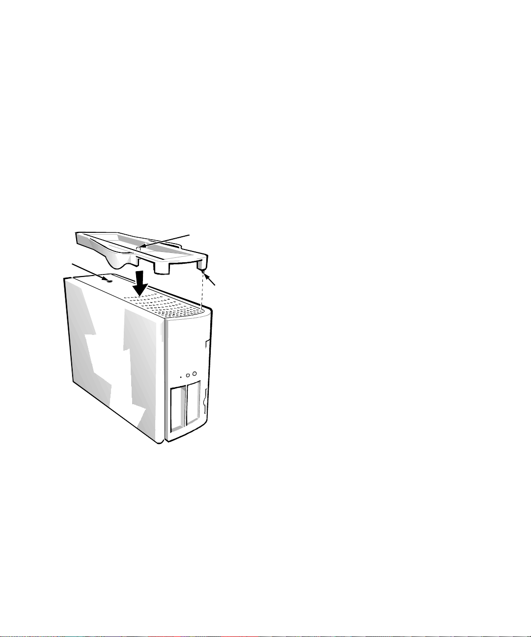
Attach the floor stand as follows:
1. Turn the computer onto its right side so that the
drive ba ys are at t he b o tto m .
2. Fit the floor stand onto what was the left side of
the comp u ter.
Position the floor stand as shown in Figure 1-1.
Align the large rou nd hole in the floor stan d with the
securing button on the side of the cover, and align
the captive thumbscrew in the stand with the screw
hole in the cover.
captiv e screw
securing
button
locator pin
Figure 1-1. Attaching the Flo or S ta nd
As you lower the stand into place, make sure the
locator pin (see Figure 1-1) heads into the corner
hole of the hole pattern as shown. When the stand is
in place, tighten the thumbscrew.
3. Rotate the computer so that the floor stand is at
the bottom and the drives are at the top.
To remove the floo r stand, turn the computer over so the
floor stand is at the top, lo osen t he screw a nd lift the floo r
stand away, and place the computer in a horizon tal
position.
F
ront Panel
Your computer’s front panel contains the foll owing indicators and controls (see Figure 1-2):
The
•
•
•
•
power bu tt on
nating current (AC) input power. The push-button switch
operates as follows:
— When the computer is turn ed off, pressing the
button turns the computer on.
— When the computer is turn ed on, pressing the
button turns the computer off. However, a lowvoltage (standb y) cu rrent is m ainta ined from t he
power supply to the switch. To completely
remove all power from the system, unpl ug the
AC power cable from its source.
For systems running Microsoft Windows 95 or
Windo ws NT with the Dell AutoShutdown service opera tional, pressing the power button
causes the system to perform an orde rly operating system shutdown before turning off. (For
more information, see “Dell AutoShutdown
Service” in Chapter 2.)
NOTE: A Display Power Manageme nt Signaling
(DPMS) monitor does not be gin warming up until
the computer to which it is attached is turned on.
Thus, some DPMS monit or s may not display a video
image until sever al seconds after you turn on your
computer.
The green
puter is receiving power.
The
hard-dis k dri ve acces s indi cator
hard-disk drive is in use. (Drive access in dicators for
diskette drives and tape drive s are located on the front of the
drives.)
The
reset butt on
your having to turn the power off and then on again.
Rebooting the system in this manner reduces stress on system components.
provides control of the system’s alter-
power indicator
reboots (restarts) y our system wit hout
lights up when the com-
lights up when a
1-4 Dell OptiPlex GXpro Systems User’s Guide
Page 27
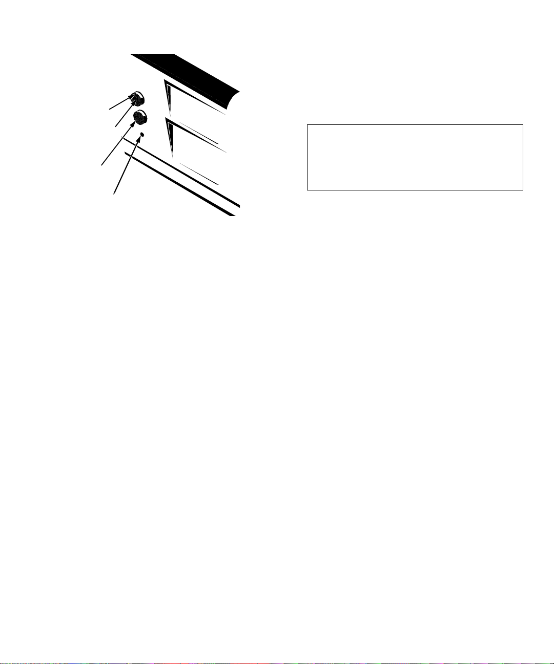
power bu tto n
Always attach external devices
turned off
any external devices, unl ess the docu mentation for the
device specifies otherwise. (If the computer does not seem
to recognize the device, try turning on the device before
turning on the computer.)
. Then turn the computer on
while your computer is
turning on
before
power indicator
reset button
hard-disk drive
access indicator
Figure 1-2. Front Panel
B
ack Panel
Your computer’s back panel con tains various ports and
connectors for attaching external de vices and includes a
securit y cab le slo t. Thes e fe at u r es ar e des cr ib e d in the
following subs ections.
Connecting External Devices
You can connect various external devices, such as a
mouse and printer, to the input/output (I/O) ports and
connectors on the computer’s back panel. The system
BIOS dete ct s t he pre s enc e of m os t ex ter nal devi ce s when
you boot or reboot your system. When connecting external devices to your computer, follow these guidelines:
Check the documentation that accompanied the
•
device for specific installation and configuration
instructions.
For example, most dev ices must be connected to a
parti cular I /O port or c o nn ecto r to ope r ate pro p er ly.
Also, extern al devic es like a mouse o r pri nter usual ly
require you to load soft ware files called
into system memory before they will work. These software
drivers help the computer recognize the exte rnal device and
direct its operation.
device drivers
CAUTION: When disconnecting external
devices from the back of the computer, wait
five seconds after turning off the computer
before you disconnect the device to avoid possible damage to the system board.
For information about en abling, di s abling, or confi guring
I/O ports and connectors, see Chapter 3, “Using the System Setup Program.” For detailed descriptions and
illustrati ons of each port and connec tor on the back panel,
see “I/O Ports and Connectors” in Appendix B.
Security Cable Slot
To the right of the fan vent on the back of t he computer is a security cable s lot (see Fi gure 1-3) for attachi ng a commer ciall y
available antithe ft de vice. Antitheft de vices for pe rsonal computers usually include a segment of galvanized cable with an
attached l o cki ng de v ice a nd ass oci ate d ke y. T o pr even t unauthorized removal of your computer, loop the cable around an
immovable objec t, ins ert t he l ocki ng d ev ice in t o t he se cur it y
cable slot on the back of your computer , and lock the device with
its associated key. Complete instructions for instal ling this kind
of antitheft devi ce are us ually i ncluded wit h the d evice.
NOTE: Antitheft devic es ar e of diff erin g design s. Befor e
purchasing such a device, make sure it will work with the
cable slot on your computer.
Introduction 1-5
Page 28
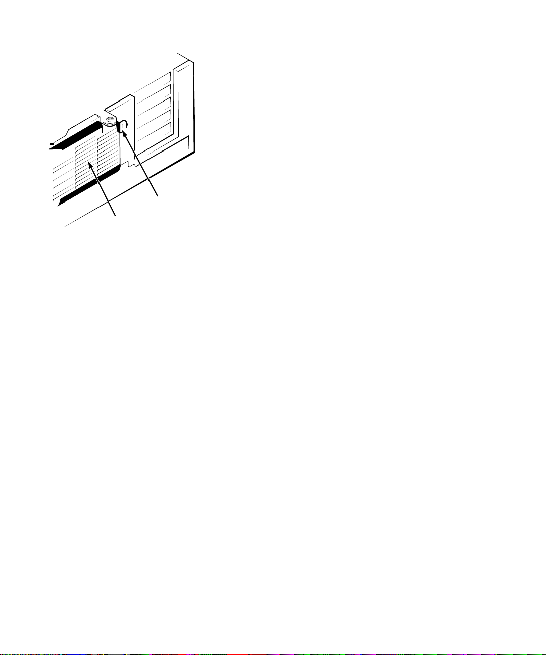
security cable slot
fan vent
Figure 1-3. Security Cable Slot
G
etting Help
If at any ti me you don’t un derst and a procedur e descr ibed
in this guide, or if your system does not perform as
expected, Dell provi des a number of tools to help you.
For more informati on on these help tools, see the chapter
titled “Getting Help” in your
ing Guide.
Diagnostics and Tr oubleshoot-
1-6 Dell OptiPlex GXpro Systems User’s Guide
Page 29

Chapter 2
Using the Software Support Utilities
Y
our Dell system comes with software support utilities
on diskette or on your c ompute r’ s hard- disk dri ve. These
software support utilities include system utilities, system
services, and bu s- masteri ng in t eg r at ed drive elec tr o n ic s
(IDE) drivers, all of which are documented in this
chapter.
NOTE: For information on the additional software support util ities you receive with your system, refer to the
following places:
Video drivers—see the documentation from the
•
video card manufacturer. (Video drivers support the
video graphics requirements of a variety of mon itors
and application programs running Micr osoft Windows NT 3.51 or 4.0, Microsoft Windows 95,
Microsoft Windows 3.x, or MS-DOS
systems.)
Audio drivers—see Chapt er 6, “Using t he Integra ted
•
Audio Controller,” of this guide.
Network interface drivers—see Chapter 5, “Using
•
the Network Interface Controller,” of this guide.
System utilities and serv ices
your system and to explicitly control certain hardwa re
features. Refer to “Sys tem Utilities and Services” found
later in th is chapter for information about these utilities.
Bus-mastering IDE drivers
Microsoft Windows 95, Windows NT 3.51, and OS/2
operating systems.
NOTE: Bus-Mastering IDE drivers are
for use with the Windows NT 4.0 operating system.
These drivers can off-load certain functions from the system microprocessor, providing a performance
improvement during multithreaded operations (instance s
where se ve r al ap pl i cat ion prog rams are run n i ng simultaneously). Refer to “Bus -Mastering IDE Drivers” found
later in th is chapter for information about these utilities.
can be used to safeguard
are provided for the
®
operating
not
yet available
®
NOTE: On each softwar e s upport diskette set yo u
receive, a readme.txt file may be included (on diskette 1
of the set) along wit h the software utilities or drivers. If
inclu de d, the readme.txt fi le contains the latest updates
to the information in this manual. Use the edit o r
included with your operating system to view and/or print
the contents of readme.txt files.
S
oftware Support Utilities on
Diskette
If software support diskettes are included with your Dell
system, the Dell system utilities and bus-mastering IDE
drivers are provi ded on these diskettes. To use one of
these utili ties or drivers, you must install the utility or
driver as described la ter in this ch apter.
D
ell-Installed Software Support
Utilities
If no software support diskettes were shipped to you, the
system utilities and bus-masterin g IDE drive r s are
already instal led on your hard-disk drive in t wo different
forms: as wor king u til it ie s, ope rativ e im medi at el y, and as
diskette images.
In case you later need to reinstall the files for any reason,
you need to copy the di sket te images to a bac kup disk ette
(see the next secti on, “Backing Up the Software Support
Utilities”). From the backup disket te, you can install the
desired file(s) to a directory on your hard-dis k drive. Further instr u ctions for installing the utilities and servic es
are provided later in this chapter.
Using the Software Support Uti li ties 2-1
Page 30

B
acking Up the Software Support
Utilities
Dell recommends that you cr eat e origi nal diske tte copi es,
or
progr am diskette sets
You will need these diskettes if you ever want to reconfigure or reinstal l your Dell-installed software. To create
program diskett es, use the Dell DiskMaker program to
create program diskette sets (available through the Dell
Accessories prog ram group or folder).
S
ystem Utilities and Services
The following utilities and services are included on your
Dell Sy stem Ut il ities
The
•
•
•
•
Asset Tag
number into nonvolatile random-access memory
(NVRAM). Thereaft er, you can display this number
using the Asset Tag utility or the System Setup
program.
The
Auto Power On
file to carry out a series of commands when your system
is powered on by the Auto Power On feature or by the
power button.
The
Dell AutoShutdown
tion of the power button by providing for an orderly
operating system shutdown when the computer system is tu r n ed of f.
The
Dell Thermal Shutdown
anisms for protecting the microprocessor against
overheating.
Asset Tag Utility
The Asset Tag utility allows you to enter an asset tag
number for your computer. The default System Setup
screens (se e Figure 3-1) do not s how the asset tag number
unless you enter one using this util ity.
NOTE: The Asset Tag utility works onl y on s ys tems running MS-DOS and Windows 95.
, of your Dell-insta lled software.
diskette:
utility lets you ent er a sys tem a sset tag
utility enables you to create a batch
service enhances the opera-
service provides mech-
Installing the Asset Tag Utility
The Asset Tag Utility is already installed on your harddisk drive. I f y ou need to reinstall the Asset Tag Utility ,
perform the following steps:
1. If you have not already done so, use the Dell DiskMaker to make a diskette copy of the
Utilities
The Dell DiskMaker is available through the Dell
Accessories program group. For more info rmation,
refer to the online help provided in the Dell DiskMaker program.
2. With the backup diskette in drive A, copy the
asset.com
your choice on your hard-disk drive.
If the
already contain the directo r y in which you reinstalled the
Asset Tag utility, modify the
that directory. (See your MS-DOS reference documentation for informati on on modi fying the
diskette image on your hard-disk drive.
file from the diskette to the directory of
statement in your
path
autoexec.bat
statement to include
path
Dell System
file does not
autoexec.bat
file.)
Using the Asset Tag Utility
After you reinstall the Asset T ag utility, you can use it to
enter an asset tag number that you or your company
assign to your comput er; you can a lso use it t o reent er the
computer’s service tag number if that becomes necessary.
Use the
existing asset ta g and s ervice tag num bers, type ass et and
press <
the System Setup progra m described i n Cha pter 3.)
Assigning and Deleting an Asset Tag Number
An asset tag number can ha ve up to ten characters; any
combination of characters excluding spaces is valid. To
assign or change an a sset tag number, type asse t and a
space followed by the ne w number; then pres s <
example, type the following command line and press <
asset 1234567890
When prompted to verify the ass et tag number, type y and
press <
asset tag number a nd th e service tag num ber.
To delete the asset tag number without assigning a new
one, type asset /d and press <
command from the syst em prompt. To view
asset
>. (You can also view the a sset ta g number us ing
ENTER
ENTER
>. The system then displays the new or modified
ENTER
>.
ENTER
>. For
ENTER
>:
2-2 Dell OptiPlex GXpro Systems User’s Guide
Page 31

Table 2-1 lists the command line options you can use
with the Asset Tag utility. To use one of these opt ions,
type asset and a s pace fo ll owed by th e opt ion .
.
Table 2-1. Asset Tag Comman d-Line Options
Asset Tag Option Descript ion
/d
Dele te s th e asset tag
number
/?
Displays the Asset Tag
utility help screen
Auto Power On Utility
The Auto Po w er On u tili ty en ab l es your sy ste m to au t omatically perform routine tasks in your absence. For
example, you might want your system to turn on at night
and perform a backup procedure. To use the utility, you
need to create a batch file containing the command(s) or
program(s) that you want performed in your absence.
The Auto Power On utility determines whether system
power was turned on by the power button or by the
POWER ON
option in the System Setup program and passes this
information on t o your batc h file, initi ating the a ppropriate commands at system start-up. See “Auto Power On” in Chapter 3
for information on using the
AUTO POWE R O N
option.
The following example shows the contents of a possible
batch file.
NOTE: The first th ree lines of your batch file mu st matc h
the first th r ee lines in the fo llowi ng e xample.
autopowr
if errorlevel 2 goto alarm
if errorlevel 1 goto button
:alarm
call alarm.bat
autopo wr /o ff
:butto n
call button.bat
goto end
autopowr/off
The
command shuts of f your computer.
AUTO
Installing the Auto Power On Utility
The Auto Power On utility is already installed on your
hard-disk drive. If you need to reinstall the Auto Power
On utility, perform the following steps:
1. If you have not already done so, use the Dell DiskMaker to make a diskette copy of the
Utilities
diskette image on your hard-disk drive.
Dell System
The Dell DiskMaker is available through the Dell
Accessories program group. For more info rmation,
refer to the online help provided in the Dell DiskMaker program.
2. With the backup diskette in drive A, copy the
autopowr.com
file from the diskette to the direc-
tory of your choice on your hard- di sk drive.
If the
path
statement in your
autoexec.bat
file does not
already contain the directo r y in which you reinstalled the
Asset Tag utility, modify the
path
statement to include
that directory. (See your MS-DOS reference documentation for informati on on modi fying the
autoexec.bat
file.)
Dell AutoShutdown Service
The Dell AutoShutdown service (available with the Windows NT and Windows 95 operating systems) lets you
perform an orderly system s hutdown and turn your system off with a single touch of the power button.
This service is already installed and operative on your
hard-disk drive. If you need to reinstall it, see “Ins talling
the Dell AutoShutdown and Thermal Shutdown Services” found later in this chapte r.
How AutoShutdown Works
The power button operates in two modes, im me diate and
AutoShutdown mode.
When the system i s off, the power button always acts in
immediate mode—tha t is, when the button is pres sed, the
system powers up immediately.
When the system is on and the AutoShutdown service is
installed, the power button operates in AutoS hutdown
mode. Pressing the power button signals the service to
perform an orderly operati ng system shutdown (reducing
the possibility of data loss and file corruption) before
removing power from the system. During the shutdown
Using the Software Support Uti li ties 2-3
Page 32

sequence, the power indicator on the front panel of the
computer flashes.
NOTE: The pre sence of the AutoShutdow n se rvice does
not affect the operation of the system reset button.
If the processor reaches th e pre set s econdary (higher)
threshold value during the shutdown process, the system
abandons the shutdo wn pr ocess and turns itself off
immediately.
If Your Operating System Locks Up
If, when you press the power button, the power indicator
begins to flash but the system does not turn off, your
operating system may have locked up. (A locked-up
operating system does not sense when the power button
is pressed.)
To ensu r e th at th e sy stem can be tu r n ed off u nder these
circumstances, a manual intervent ion m ec hanism has
been included in the software. To turn off a locked-up
system, either press the power button a second time or
press the reset button.
NOTE: This sce nario (a locked-up system with the
AutoShutdown service active) is the only situation in
which pressing the reset button will turn off the system
without rebooting it.
Dell Thermal Shutdown Service
The Dell Thermal Shutdown service helps protect the
system microprocessor from damage due to overheating. It can also protect your system data from loss or
corruption resulting from a thermal-related system
shutdown.
For the Windows NT and Windows 95 operating systems, this service should already be installed and
operative on your hard-disk drive. Shoul d you need to
reinstall it for any reason, see “Installing the Dell
AutoShutdown and Thermal Shutdown Services” found
later in this chapter.
How Thermal Shutdown Works
When installe d, the service uses sensors located beneath
the microprocessor to monitor the microprocessor’s temperature. If the processor begins to overheat and reaches
the preset p r im ary (lower) threshold temperature, the system first performs an orderly operatin g sy st em shutdown
and then turns itself off. During the shutdown phase, the
power indica tor flashes and a scree n message noti fies the
user that the syste m is shutting down.
CAUTION: Whether or not the Thermal Shutdown service is installed , the temperature sensors
are always installe d and operational. If the service
is not installed and the processor overheats to the
primary (lower) threshold value , the system turns
off immediately—with no attempt to perform an
orderly operating system shutdown.
Installing the Dell AutoShutdown and
Thermal Shutdown Services
For systems running the W indows NT and Windows 95
operating systems, Dell installed the AutoShutdown and
Thermal Shutdown services on the hard-disk drive both
as working utilities and as diskette images.
If you need to reinstall one or both of these services, perform the following steps:
1. If you have not already done so, make a diskette
copy of the Dell System Utilities diskette image on
your hard-disk drive.
Use the Dell DiskMaker (available through the Dell
Accessories program group) to create a prog ram diskette from the diskett e image. For more info rmation,
refer to the online help provided in the Dell DiskMaker program.
2. With the backup diskette in drive A, run the
setup.exe
3. At th e Welcom e s c reen , cli ck
4. Se le ct t h e service( s) yo u w a nt to ins t a ll and then
click
5. Click
activate the new service(s).
program from the diskette.
NEXT
.
NEXT
.
YES
and th e n OK to reboot Windows and
Removing a Service
To re mov e a service , pe rform the following steps:
1. Insert the backup diskette into drive A.
2. Run
remove.exe
from the disket te.
2-4 Dell OptiPlex GXpro Systems User’s Guide
Page 33

3. Select the servic e(s) you want to r emove and click
NEXT
.
4. When prompted to restart Windows, first click
OK
, and then
EXIT
and restart Windows.
D
ell Energy Manager
The Dell Energy Manager, a utility available only on systems running the Windows 3.1 operating system, allows
you to control your computer’s energy conservation features. If your sy st em has Dell-installed Windows 3.1, the
Dell Energy Manage r is already insta ll ed and operationa l
on your syste m’s hard-disk drive.
To access the Dell Energy Manager utility, double-click
the Power icon in the W indows Control Panel (located in
the Main program group), and then click the Options
button. For instructions on using this uti lity, click the
Help button to access the Dell Energy Manager online
help.
NOTE: You can use this utili ty to custom-set the time-out
periods for your monitor an d hard-disk drive. If you deviate fr o m th e st andard
settings available through the
egory in the System Se tup program, the
MANAGEMENT
MAXIMUM, REGULAR
POWER MANAGEMENT
catego r y d isp l a ys th e
CUSTOM
POWER
, and
setting.
MINIMUM
cat-
Installing the Dell Energy Manager
For systems running the Windows 3.1 operating system,
Dell has i nsta lled t he Dell En er gy Mana ger utili ty a s both
a working utility and as a diskette image.
If you need to reinstall the utility, perform the following
steps:
1. If you have not already done so, make a diskette
copy of the D ell Energy Manager diskette image
on your hard-disk drive.
Use the Dell DiskMaker (available through the Dell
Accessorie s prog ram gr oup) to create a program diskette from t he diskette i mage. For more information,
refer to the online help provided in the Dell DiskMaker program.
2. With the backup diskette in drive A, run the
setup.exe
3. At the Dell Energy Manager Setup scree n , cl ick
CONTINUE
to a default directory.
program from the diskette .
to automatically copy the diskette files
B
us-Mastering IDE Drivers
Bus-mastering IDE drivers (provided for W indows 95,
Windows NT 3. 5x, and OS/2) bring about a performance
improvement by off-loading certain functions from the
system microprocessor during multithreaded operation
(several application programs running simultaneously).
The bus-mastering driver for your operating system has
been preloaded at the factory and is operative when you
receiv e y o ur co mp u t er.
The drivers for Windows NT 3.5x and OS/2 have also
been copied to your hard-dis k drive in diskette -im age
form. If you need to reinstall either of these drivers, you
can do so as described in the following subsections.
NOTE: Bus-Mastering IDE drivers are
for use with the Windows NT 4.0 operating system.
not
Windows NT 3.5x
To re install the bus-mastering IDE drivers for Windows
NT 3.5x, perform the following steps:
1. If you have not already done so, use the Dell DiskMaker to make a diskette copy of the Dell Bus
Mastering ID E Drive rs diskette image on your
hard-disk drive.
The Dell DiskMaker is available through the Dell
Accessories program group. For more info rmation,
refer to the online help provided in the Dell DiskMaker program.
2. Boot your system and log onto Windows NT. If
you are already running Windows NT, close any
open documents or application programs.
3. Insert the Dell Bus Mastering IDE Drivers diskette into drive A.
RUN
4. From the File menu, sel ec t
5. In the Command Line box in the Run window,
type a:\nt\setup.exe to start the installation
procedure.
6. To read and then t o agree to the license ag ree-
YES
ment, click
twice.
.
yet available
Using the Software Support Uti li ties 2-5
Page 34

7. To accept the default directory in which to install
the driv er s (
c:\piixide
), click
OK
.
8. When the system asks if you want to view the
readme.txt
file, click
NO
and continue foll owing
the steps in this procedure.
9. When the license agreement and Program Manager reapp e ar on t he s cre en , retur n to the
Program Manager.
10. From the Program Manager, double-click the
Windows NT Setup icon in the Main program
group.
11. Fro m t he menu bar, select
SCSI ADAPTERS
.
OPTIONS|ADD/REMOVE
12. In the SCSI Adapter Setup dialog box, click
ADD...
.
13. When a message explaining how to re cover from
a bad installation is displayed, click
OK
.
14. In the Select SCSI Adapter Option dialog box,
OTHER (REQUIRES A DISK FROM A HARDWARE
select
MANUFACTURER)
from the Adapter menu.
15. In the Insert Diskette dialog box, type
c:\piixide to specify the driver installation
directory.
16. In the Select OEM Opt ion dialog b ox, sel ect
PIIX PCI SCSI BUS MASTER IDE CONTROLLER
OK
click
.
INTEL
and
The Select SCSI Adapter Option dialog box reappears, now listing
MASTER IDE CONTROLLER
17. Click
INSTALL
INTEL PIIX PCI SCSI BUS
in the Adapter menu.
.
18. If the Windows NT Setup dialog box does not list
the corre ct d ri ve r install at i o n di rec t or y, type
c:\piixide. Click
CONTINUE
.
To signal a successf ul installation, the SCSI Adap ter
Setup dialog box reappea rs, with
MASTER IDE CONTROLLER
INTEL PIIX PCI BUS
listed in th e Ad ap ter
menu.
19. Click
CLOSE
to exit the dialog box, select
EXIT
from the NT Setup Options menu, and click OK
on the message about rebootin g.
20. Select
SHUTDOWN
from the Program Manager
File menu.
21. From the Shutdown Computer dialog box, select
SHUTDOWN AND RESTART,
and then click OK.
OS/2
To install the bus-mastering IDE drivers for OS/2, perform the following procedure:
1. If you have not already done so, use the Dell DiskMaker to make a diskette copy of the Dell Bus
Mastering ID E Drive rs diskette image on your
hard-disk drive.
The Dell DiskMaker is available through the Dell
Accessories program group. For more info rmation,
refer to the online help provided in the Dell DiskMaker program.
2. Boot your system under OS/2. If you are already
running OS/2, close any open documents or application programs .
3. Insert the Dell Bus Mastering IDE Drivers diskette into drive A.
4. Open an OS/2 command line window. At the
prompt, type a:\os2\setup.exe to start the
installation procedure.
5. Follow the o n -s cre en in s t ru c t io n s t o co p y th e
driver files to the hard-disk drive.
At the conclusion of this process, you can find further instal la tio n inst ruct ion s i n the
the
c:\piixide
6. Print the
directory.
readme.txt
file and use it to complete the
installation procedure.
readme.txt
file in
2-6 Dell OptiPlex GXpro Systems User’s Guide
Page 35

Chapter 3
Using the System Setup Program
E
ach time you turn on your computer system or press
the res et button, the system compares the hardware
installed in the system to the hardware listed in the sys tem configurati on information stored in nonvolatile
random-access memory (NVRAM) on the system
board. If the system detects a dis crepancy, it generates
error messages that identify the incorrect configuration
settings. The system then prompts you to enter the System Setup pro gr am to correct the setting.
NOTE: Do not use the System Setup in structions on the
card titled
System
You can use the System Setup program as follows:
•
•
Yo u can
change
tem before the change takes effect.
After you set up your system, run the System Setup
program to familiarize yourself with your syste m
configuration information and optional settings. Del l rec ommends that you pr int out t he Syst em Set up screen s (by
pressing th e <
mation for future reference.
Before you use the System Setup program, you need to
know the kind of diskette drive(s) and hard-di sk drive(s)
installed in your computer. If you are unsure of any of
this information, se e the manufactu r ing test report that
was shipped with your system. You can access the manufacturing test report from the Dell Accessories folder or
program group.
Frequently Asked Questions About Your Dell
—these instructions are incorrect for your system.
To change the system configuration information
after you add, change, or remove any hardware in
your system
To set or change user-sel ec table options—for example, the time or date on your system
the current settings at any time. When you
view
a setting, in many cas es you must reboot the sys-
PRINT SCRN
> key) or w r ite dow n th e infor -
E
ntering the System Setup
Program
To enter the System Setup program, press the System
Setup key combina ti on durin g th e sys tem’s power-on self
test (POST), as follows:
1. Turn on (or reb o ot) your system.
2. During the boot routine, the message Press
<CTRL><ALT><ENTER> for System Setup
appears on the screen. When the message
appears,
<
ALT
The message
..... Please wait
replaced by Page 1 of the System Setup screens.
If you wait too long to press the <
key combinatio n, the
for System Setup
operating system begins t o load into memory. If this situation occurs,
then shut it down and try again.
NOTE: To ensure an orderly sys tem shutdown, consult
the documentation that accompanied your operating
system.
You can also enter the System Setup program by
responding to certain error messages. See “Responding
to Error Messages” at the e nd of this chapter.
immediately
> keys and press the <
Entering System Setup
let the sys tem complete the load operation
hold down the <
Press <CTRL><ALT><ENTER>
message disappears and your
CTRL>
> key.
ENTER
appears and is soon
CTRL><ALT><ENTER
and
>
;
Using the System Setu p Progr am 3-1
Page 36

S
ystem Setup Screens
The two System Setup screens, Page 1 and Page 2, display the current setup and configuration information and
optional settings for your system. (Typical examples are
illustrated in Figure 3-1.) Informati on on the two System
Setup screens is organized in five boxed areas:
•
Title Box
The box at the top of both scree ns list s the pag e number (Page 1 or Pa ge 2) a nd the re visi on numb er of t he
basic input/output system (BIOS).
•
Configuration Options
The box on the left half of both screens lists the categories that defin e the installed hardware in your
computer.
Fields beside the categories contain options or values. You can change those that appear bright on the
screen. Options or values that you cannot change
because they are d etermined by the sy stem appear
less bright.
Some categories have multiple fields, which may
show options or values as bright or less bright,
depending upon what options or values you ente red
in other fi elds.
•
Help
The box on the upper-right half of both screens di splays help information for the categ ory with a
currently highlighted field.
•
System Data
The box in th e lo w er-rig h t co rn er of bot h sc r ee ns
displays information about your system.
•
Key Fu ncti ons
The line of boxes across the bot tom of bot h scre ens l ists
keys and their func tio ns within the S ystem Set up program.
U
sing the System Setup Program
Ta ble 3-1 lists the keys you use to view or change information on the System Setup screens and to exit the
program.
Table 3-1. System-Setup Navigation Keys
Keys Action
or
or
or
or
Moves to the next field.
Moves to the previous field.
Cycles through the options in a
field. In many fields, you can
also type in the appropriate
value.
Scrolls through help information.
Switches between P ages 1
and 2.
Exits the System Setup program without rebooting the
system and returns the system
to its previous state—the boot
routine or operating system
prompt.
For most of the categories , any
changes you made are rec orded
but do not take effec t until the
next time you boot the system.
For a few categories (as noted
in the help area) the changes
take eff ect immediately.
Exits the System Setup program and reboots the system,
implementing a ny changes you
made.
CAUTION: Any unsaved
data in open application programs will be lost when you
use this key combination.
3-2 Dell OptiPlex GXpro Systems User’s Guide
Page 37

config uration options
Page 1 of 2
Dell Computer Corporation
System OptiPl ex GXpro 200 Setup
title box
help
BIOS Version:
Time: 13:17:02
Diskette Driv e A:
Diskette Driv e B:
Drive A Lo ca ti on : Top
Drives:
Date: Mon Jan 6, 1997
3.5 inch, 1.44 MB
Not Insta ll ed
Primary Type Cyls Hds Pre LZ Sec Size
Drive 0: Auto 524 32 -1 524 63 540
Drive 1: None
Second ar y
Drive 0: Auto Packet Interface Device
Drive 1: None
Base Memory: 640 KB
Extended Memory: 63 MB
Reserved Memory: None
Fast Video BIOS: On
CPU Speed: 200 MHz
Tab,Shift-Tab change fields
key funct ions
change values Esc exit
Dell Co mp ute r Co rporation
Page 2 of 2
Keyboard Errors:
System Password:
Password Status:
Boot Sequence:
Setup Password:
Auto Power On:
Power Managem ent:
System OptiPlex GXpro 200 Setup
Report
Not Enabled
Unlocked
Diskett e Fi rs t
Not Enabled
Mon-Fr i 07 :30
Regular
Integrated Devices
Sound: On
NIC: On
Mouse: On
Serial Port 1: Auto
Serial Port 2: Auto
Parallel Port: 378h
Parallel Mode: AT
IDE Hard Disk: Auto
Diskette: Auto
Speaker: On
change val ues
This category sets the time in
24-hour forma t (hours:minutes:
seconds) for the internal clock/
calendar.
To chang e th e va lu e in a field,
enter a number or use the leftor right-arrow key.
Microprocessor: Pentium Pro-200
Level 2 Cache: 512 KB Integrated
System Memory: 64 MB ECC
Service Tag:
Alt-P ne xt
system data
XXXXX
Alt-B reboot
BIOS Version:
This category determines whether
keyboard-related error messages are
reported at system startup.
Microprocessor: Pentium Pro-200
Level 2 Cache: 512 KB Inte grated
System Memory: 64 MB ECC
Service Tag:
Alt-P ne xtTab,Shift-Tab change fields
XXXXX
Esc exit
Alt-B re bo ot
Figure 3-1. System Setup Screens
Using the System Setu p Progr am 3-3
Page 38

S
ystem Setup Categories
The following subs ec tions explain in detail each of the
categories on the System Setup screens.
Time
resets the time on the computer’s internal clock.
TIME
Time is kept in a 24-hour form at (
). To change the time, press the right-arrow key to
onds
hours:minutes:sec-
increase the number in the highlighted field or press the
left-arrow key to decrease the number. If you prefer, you
can type in numbers in each of the appropriate fields.
Date
resets the date on the computer’s internal calendar.
DATE
Your system automatically displays the day of the week
corresponding to the settings in the three fields that follow (
month, day-of-month
, and
year
).
To change the date, press the right-arrow key to increase
the number in the highli ghte d field or press t he left -arrow
key to decrease the number. If you prefe r, you can type in
numbers in the
month
and
day-of-month
fields.
Diskette Drive A and Diskette Drive B
DISKETTE DRIVE A
and
DISKETTE DRIVE B
type(s) of diskette drive(s) installed in your computer.
The standa rd con figur at ion for th is s yst em i s on e 3.5-inc h
diskette drive installed at the top of the drive cage. This
drive is designat ed
DISKETTE DRIVE A
only diskette drive in the computer.
If you install a second diskette drive, it must be a 5.25-inch
drive located in one of the two lower bays of the drive
cage. A second drive is normally designated as
DRIVE B
. To reverse the drive designations, see the next
subsection, “Drive A Location.”
The relative positions of the two drive options always
match the physical locations of the drive s in your computer—the drive listed on top is the top drive in your
computer.
The options are:
5.25 INCH, 360 KB
•
5.25 INCH, 1.2 MB
•
identify the
and is no rmall y the
DISKETTE
3.5 INCH, 720 KB
•
3.5 INCH, 1.44 MB
•
NOT INSTALLED
•
NOTE: Tape drives are
A
DISKETTE DR IVE B
and
not
refle cte d i n the
categories. For example, if you hav e a
DISKETTE DR IVE
single diskette driv e and a tape drive att ached to the di skette/
tape driv e inte rface cable, set the
DISKETTE DRIV E A
match the characteris tics of the diske tte dr ive and set the
KETTE DRIVE B
category to
NOT INSTALLED
category to
DIS-
.
Drive A Location
DRIVE A LOCATION
(the default opti on) or
drive A, the boot drive.
The letters A and B in the cate gories
DISKETTE DRIV E B
LOCA TION
is changed to reflect the new configuration.
If an external diskette drive controller is being used,
DRIVE A LOC A TI ON
controls which diskette drive—
BOTTOM
(if existing)—is used as
DISKETTE DR IVE A
switch places automatically when
becomes a nonselectable category .
TOP
and
DRIVE A
Drives: Primary and Secondary
PRIMARY
enhanced integrated drive electronics (EIDE) interface
connecto r (label ed “IDE1”) on the system board ;
ONDARY
EIDE interface connector (labeled “IDE2”).
For both the
the
hard-disk drives installed in the computer. For each drive,
seven parameters can be chosen as a group by drive-type
number, entered individually from the keyboard or set automatically. A
hard-disk drive based on a t able recorde d in the sys tem’ s BIOS.
To choose a setting for these ca tegories, type characters
from the keyboard or use the left- or right-arrow key to
cycle through th e ch o ices.
The options are:
•
•
•
•
identif ies driv es at ta ched to th e primar y
identifies drives connected to the secondar y
and the
DRIVE 1
SECONDARY
categories identify the type of EIDE
specifi es the param eter s of a
DRIVE 0
AUTO
NONE
USR1
PRIMARY
and
drive-type number
or
USR2
A specific drive-type number
SEC-
drive sections,
3-4 Dell OptiPlex GXpro Systems User’s Guide
Page 39

NOTE: Operating syste m s tha t bypass the system BIOS
may not obtain optimum hard-disk drive performance.
EIDE Devices Other Than Hard-Disk Drives
For EIDE CD-ROM and EIDE tape drives that use the
built-in EIDE controller, it is recommended that you us e
the secondary EIDE int erfa ce connector.
For al l EIDE de vices tha t are no t h ard- disk d r ives , set t he
appropriate
DRIVE
category to
AUTO
.
EIDE Hard-Disk Drives
For EIDE hard-disk drives, the system provides an automatic d r iv e-type detect feature. To use th is feature for
highlight the
DRIVE 0
,
). To use it for
matic
DRIVE 1
each case, th e category setting ch anges to
reboot the system, the System Setup program automat ically sets
the correct drive-type number and parameters fo r each drive.
Before insta lling a new EIDE hard-disk drive, also check
the docu mentation that ca me with the d r iv e to verify that
all jumper settings on the drive are appropriate for your
configurati on.
If You Have a Problem
If the system generates a drive error message the first
time you boot yo ur syste m afte r install ing an EI DE drive,
it may mean tha t y our parti cu lar driv e d oes not work with
the automatic drive-type detect feature. If you suspect
that your problem is related to drive type, tr y entering
your drive-type in format ion in one of the followi ng ways.
If You Know the Drive-Type Number
Use the drive -type number you found in the documentation that came with the drive or, if the drive was installed
by Dell when you purchased your system, on the m anufacturing test report that was shipped with your system.
To set the drive-t ype num ber in the System Setup program, highlight the appropriate drive category (
) and type in the correct drive-type number. If you prefer,
DRIVE 1
you can press the right - or left-arrow key to increase or de crease,
respectively , the drive-type number until the correct one is
displayed.
category and type a (for
DRIVE 0
, type a at the
DRIVE 1
AUTO
auto-
category . In
. After you
DRIVE 0
or
If You Do Not Know t h e Drive-Type Number
The
DRIVE 0
and
categories dis play the fo llowing seve n
DRIVE 1
parameters for each drive type:
is the dr ive-type number f o r the selected hard-
TYPE
•
disk drive.
is the number of logical cylinders.
CYLS
•
indicates the number of logical heads in the
HDS
•
drive.
•
prec ompensation cylinder
(
PRE
) is the cylinder num ber at which the electrical current for the drive head
changes to compensate for differences in data density across the disk surface (this parameter has no
effect for EIDE drives).
is the cylinder number that is used as the
LZ
•
drive’s landing zone for the heads when the drive
is not in use.
is the number of logical sectors per trac k.
SEC
•
(automatically cal culated by the system) indi -
SIZE
•
cates the number of millions of bytes of storage
provided by the drive.
If none of th e supporte d dri ve typ es m atch t he par ameters
of your new drive, you can enter your own parame ters.
To do so, highlight the appropriate drive category (
0
or
DRIVE 1
) and type u to display
. You can then
USR1
DRIVE
use the right- or left-arrow key to switch between the
USR1
and
settings . Then press the <
USR2
TAB
> key to
highlight each of the parameter fields in succession, and
enter the appropri ate nu mber for each field. You can have
only two user-defin ed drive types.
and
NOTE: The
PRIMARY
the
USR1
and
However, if you select the
obtain optimum har d-di sk driv e performance. Also, t he
USR2
and
drive types cannot be use d for har d-disk drives
USR2
drive types can be used for bot h
SECONDAR Y DRIVE 0
or
USR1
USR2
DRIVE 1
and
categories.
drive type, you may not
USR1
greater t han 528 megaby tes (MB) i n capacit y .
Base Memory
BASE MEMORY
to MS-DOS programs that do not use extended or
expanded memory. This category has no user-selectable
options.
displays the amount of memory ava ilable
Using the System Setu p Progr am 3-5
Page 40

The defa ult value for th e
BASE MEMORY
which includes 1 kilobyt e (KB) reserve d for sy stem use
category is
640 KB
.
Extended Memory
EXTENDED MEMORY
options, indicates the amou nt of memory available as
extended memor y . The value giv en is in megabyte s rather
than kilobytes. To convert megabytes to kilobytes, multiply the megabyte total by 1024.
, which has no user-selectable
Reserved Memory
RESERVED MEMORY
system board memory tha t can be supplied by an expansion card. You should not enable the r es erved memory
feature unless you are using an expansion card that
requires special addressing.
For example, you may have a memory expansion card
that needs to be addressed starting at 15 MB. Selecting
the
15M - 16M
specifies that only part of the base memory comes from the
dual in-line memory modules (DIMMs) on the system board,
whereas the base memory from 15 MB to 16 MB comes from
the memory expansion card.
RESERVED MEMORY
The
(the default option)
NONE
•
15M - 16M
•
512K - 640 K
•
allows you to designate a region of
option in the
RESERVED MEMORY
category has the following options:
category
Fast Video BIOS
FAST VIDEO BIOS
caching the BIOS for an Industry-Standard Arc hitecture
(ISA) video graphics arra y (VGA) card ins talled in an
expansion slot.
NOTE: Peripheral Compon ent Interconnec t (PCI) video
cards are always shadowed and cached.
FAST VIDEO BIOS
The
(the default opt ion)
ON
•
OFF
•
offers the option of shadowing and
category has the following options:
,
If you choose the ON option, when your syste m boots it immediately copies the v ideo ca rd’ s BIOS c ode into write-pr otected
memory locations in fast random-access memory (RAM). (This
option also allows the
process is known as
shadowing.
BIOS code to be cach ed .
Caching
ON
) The
speeds sys tem perf ormance
by retaining the most rec ently acce ssed data a nd inst ructions in
an intermediate stora ge area of static RAM (SRAM), which is
faster than system RAM.
Although
FAST VIDEO BIOS
should normally be set to ON,
some video cards are not de signed to be shado wed or ca ched. If
this category is se t to
setting
FAST VIDEO BIOS
and you experience video problems, try
ON
to
.
OFF
CPU Speed
CPU SPEED
system boots.
Press the left- or right-arrow key to toggle the
SPEED
rated speed (the default ) and a lowe r compati bil ity sp eed,
which lets you accommodate speed-sensitive application
programs.
indicates the proce ssor s peed at which your
category between the res ident microprocessor’s
Num Lock
NUM LOCK
the Num Lock mode activated on 101- or 102-key keyboards (it does not apply to 84-key keyboards).
When Num Lock mode is activated, the rightmost bank
of keys on your keyboard provides the mathematical and
numeric functions shown at the tops of the keys. When
Num Lock mode is turned off, each key provides the
cursor-control functi on (i f any) indi cate d at the bot tom of
the key.
determines whether your system boots with
Keyboard Errors
KEYBOARD ERRORS
board errors during the POST, which is a series of tests
that the system performs on the hardware each time you
turn on the system or press the r es et button.
This category is us eful when applied to self-starting servers or host systems tha t have no permanently attach ed
keyboard. In thes e s ituations, selecting
enables or dis ables reporting of key-
DO NOT REPORT
CPU
3-6 Dell OptiPlex GXpro Systems User’s Guide
Page 41

suppresses all error messa ges relating to the keyboard
or to the keyboard controller during POST. This
option does not affect the operation of the keyboard
itself , if one is att ach ed to the com pu ter.
System Password
SYSTEM PASSWORD
system’s password security feature and allows you to
assign and verify a ne w password. No one can assign a
new password unless the current status is
which is display ed in bright characters.
The options for the
NOT ENABLED
•
ENABLED
•
DISABLED BY JUMPER
•
NOTE: Read “Using the System Password Feature”
found later in this chapter for detailed instructions on
assigning a system password and using or changing an
existin g sy stem password. See “Disabling a Forgotten
Passwor d” found lat er in this chapter for inst ructions on
disabling a forgotten system password.
displays the current status of your
NOT ENABLED
SYSTEM PASSWORD
category are:
(the default option)
Password Status
PASSWORD STAT US
security by letting you set the system password to
LOCKED
or
UNLOCKED
Using With a System Password Enabled
When this ca tegory is
knows the system password can disable the passwo rd at
system start-up by us ing the <
played on the screen—th us (inadvert ent ly or not) leav ing
the system without password protection .
When this ca tegory is
the password at system s tart-up , th e followi ng mess age is
displayed :
Passwo rd lo ck ed , not disabled
To provide maximum securit y for your sy st em, ope rate
the system with
PASSWORD ENABLED
Then, if you want to let selected i ndividuals use your system, give them the system password
password
. In this way, even those who know the system
provides an extra measure of system
.
UNLOCKED
LOCKED
SYSTEM PASSWORD ENABLED, SETUP
, and
, any user who already
CTRL><ENTER
> option dis-
and a user tries to disable
PASSWORD STATUS LOCKED
but not the setup
password cannot dis able it at system st art- up and will not
be able to unlock it in the System Setup program in orde r
to change or disable it.
Using Without a System Password Enabled
In situations where the syste m admi nistrator does not
want to use a syst em passw ord, t his ca tegory can be used
to guard against a user assigning a password. With
and
WORD STATUS LOCKED
ENABLED
,
cannot enter the System Setup program and unlock the
, a user who does not know the setup password
SETUP PASSWORD
system password in order to a ssign one.
Boot Sequence
BOOT SEQUENCE
default option) or
The term
boot
cedur e. When t u r n ed on, t h e sy s t em “boo t st r ap s”
itself into an operational state by loading into memory
a sm al l p r o g r am, whi ch in tu r n loads the neces sary
operating system.
where to look for the files that it needs to load.
Selectin g
DISKETTE FIRST
booting from drive A first. If it finds a diskette that is
not bootable in the drive or finds a problem with the
drive itself, the system displays an er r or message. If it
does not find a diskette in the drive, the system then
tries to boot from the hard-disk drive (drive 0).
Selecting
only
HARD DISK ONLY
from th e ha rd- dis k d rive , ev en if the re is a b oot -
able diskette in drive A.
can be set to
HARD DISK ONLY
DISKETTE FIRST
.
refers to the system’s start-up pro-
BOOT SEQUENCE
tells th e sys tem
causes the system to try
causes the system to boot
Setup Password
SETUP PASSWORD
puter’s System Setup program in the same way that you
restrict access to your system w ith th e system pa sswo rd
feature. The options are:
NOT ENABLED
•
ENABLED
•
DISABLED BY JUMPER
•
.
NOTE: Read “Using the Setup Password Feature”
found later in this chapter for deta iled instructions on
assigning a setup password and using or changing an
lets yo u r estrict access to yo u r co m -
(the default opti on)
PASS-
(the
Using the System Setu p Progr am 3-7
Page 42

existin g se tup passwor d. See “Disabling a Forgotten
Passwor d” found lat er in this chapter for inst ructions on
disabling a forgotten setup password.
Auto Power On
AUTO POWER ON
feature (included with your software utilities) to turn
your computer system on automatically on certain days
of the week at a preset time. You can set
to turn on the system either every day or every Mon-
ON
day through Frida y.
NOTE: This feature will not work if you shut off your
system using a power strip or surge protector.
Select a daily schedule (
use the down-arrow key to hig hlight first the hours field
and then the minutes field. Time is kept in a 24-hour format (
hours:minutes
the right-arrow ke y to increase the number in the highlighted field or press the left-arrow key to decrease the
number . If you prefe r , you c an type in numbe rs in both of
the appropriate fields.
The default for
allows you to use the Auto Power On
AUTO POWER
EVERYDAY
or
MON-FRI
) and then
). To change the start-up time, press
AUTO POWER ON
is
DISABLED
.
Power Management
For certain types of monitors and most EIDE hard-disk
drives, you can reduce system power consumption by
enabling the power management feature. With
MANAGEMENT
enabled , th es e mon ito rs a nd driv es aut omat ically switch into low-power mode during periods of system
inactivity.
POWER MANAGEMENT
levels—options are
can be implemented at three
MAXIMUM, REGULAR
(The different levels apply to the monitor only; hard-disk
drive operation is the same for all thr ee.) The feature can
also be set to
DISABLED
.
NOTE: The Dell Energy Manager util ity (available only
on systems running the Windows 3.1 operating system)
lets you assi gn time-out settings that deviate from the
predefined
MAXIMUM, REGULAR
available t hr oug h the
POWER MANAGEMENT
, and
MINIMUM
you have used the Dell Energy Manager to customize
your time-out periods, the
gory may display
CUSTOM
POWER MANAGEMENT
as its setting. (For more
information on the Dell Energy Manager, see “Dell
Energy Manager” in Chapter 2.)
POWER
, and
MINIMUM.
settings
category. If
cate-
Saving Monitor Power
If you have a Vi deo E lectronics Standards Assoc iation
®
(VESA
compliant monitor, enabling the
) Display Power Manageme nt Signal in g (DPMS)-
POWER MANAGEMENT
category red uces monit or power consum ption du ring periods
of keyboard and mouse ina ctivi ty.
NOTE: The power management feature monitors activity of
a mouse connected to the Personal System/2 (P S/2)compatible mouse port.
CAUTION: Check your monitor documentation
to make sure you have a DPMS-compliant monitor
before you enable this feature. Otherwise, you risk
damaging the monitor.
By setting
or
MINIMUM
POWER MANAGEMENT
, you can set predef ined time-out periods (see
to
MAXIMUM, REGULAR
Ta ble 3-2) for the two success ive monit or shutd own sta ges,
and
standby
off
.
NOTE: Each monitor man ufac turer defines the detail s of
the shutdown st ages for its own monitors. But in all
cases, power cons umption decreases with each st age
from “on” (full powe r) to “standb y” (reduced power; the
display image usual ly disa ppears) to “off” (where power
consumption is minimal). To define these stages for your
monitor, see the documentation that came with the
monitor.
From any of these shutdown stages, you can return full
power to the monitor in one of the following ways:
For most DPMS-compliant monit ors, any subse-
•
quent activity—including moving the mouse—
should return full power to the monitor.
A few DPMS-compliant monitors require that you
•
turn monitor power of f and the n on again t o return to
full power.
Check your monitor docum entation for information on
how your monitor is designed to operate.
Saving EIDE Hard-Disk Drive Power
For most systems, enabling
POWER MANAGEMENT
level causes EIDE hard-disk drive s to switch to low-power
mode after about 20 minutes of system inactivity .
at any
,
3-8 Dell OptiPlex GXpro Systems User’s Guide
Page 43

NOTE: Not all EIDE hard-disk drives support this feature. Enabling this feature for drives that do not support
it may cause the EIDE drive to b ecome inoperable until
the computer is restarted and the
POWER MANA GEMEN T
category is d isabled.
In low-power mode, the disks inside the drive stop spinning. They remain idle until the next drive access, which
causes them to start spinning again. (Because the disks
take a few seconds to regain full speed, you may notice a
slight delay when you next access the hard-di sk drive.)
When
POWER MANAGEMENT
is
DISABLED
(the
default), the disks spin constantly as long as the system is tu rned on .
Table 3-2. Power Time-O ut Periods
Power
Management
Setting
EIDE Drive
Spindown
Time-Outs
Moni tor
Standby
Time-Outs
Monitor
Off
TimeOuts
Disabled Never Never Never
Maximum 20 minutes 10 minutes 1 hour
Regular 20 minutes 20 minutes 1 hour
Minimum 20 minutes 1 hour Never
Serial Port 1 and Serial Port 2
SERIAL PORT 1
and
SERIAL PORT 2
tem’s built-i n ser ia l por t s. Th ese cate gor i es can be set to
(the default opti on) to automatically con f igure a
AUTO
port to a pa rticular designation (
SERIAL PORT 1; COM2
to disable the port.
OFF
If you set a serial port to
or
COM4
AUTO
containing a port c onf igur ed to the same desi gnati on, the s ystem automati ca lly r emap s the bui lt -in port to the next
available port desi g nation that shares the same I RQ setting:
COM1 (input/outp ut [I/O] address 3F8h), which
•
shares IRQ4 with COM3, is remapped to COM3
(I/O address 3E8h).
Likewise, COM2 (I/O address 2F8h), which shares
•
IRQ3 with COM4, is rema pped to COM4 (I/O
addr ess 2E 8 h) .
(Note that when two COM ports share an IRQ setting,
you can use either port as ne cessary, but
able to use them both at the same time
port (COM3 or COM4) is also in use, the bui lt-in port is
turned off.
For more inform ation about built-in ports, port designations, IRQs, and the rem apping of ports, see “I/O Ports
and Connectors ” in Appendix B.
configure the sys-
or
COM1
for
SERIAL PORT 2
COM3
for
) or to
and add an expansion card
you may not be
.) If the second
Sound
determines whether the integrated audio control-
SOUND
ler is
(the default) or
ON
. Set this ca tegory to
OFF
OFF
you want to use a sound expansion card instead of the
integrated audio controller or if you need the resources
used by the controller. You must reboot your system
before a change takes ef fec t.
NIC
determines whether the net work interface controller
NIC
or
(NIC) is
ON
. You must reboot your system before
OFF
a change takes effect.
Mouse
MOUSE
compatible mouse port. Disabling t h e mouse allow s an
expansion card to use interrupt request (IRQ) 12.
enables or disab l es the system’ s built-in PS/2-
if
Parallel Port
PARALLEL PORT
port. This category can be set to
alternat e a dd re sse s
port.
The default sett ing is
setting unle ss an expansion card needs to use that
address.
configur es the system’s built-in parallel
(the default), to
378H
278H
or
378H
3BCH
or to
,
to disable the
OFF
; you should leave it at that
Parallel Mode
PARALLEL MODE
parallel port act s as an AT-compatible (unidirecti onal) or
PS/2-compatibl e (bidirectional) port.
Your system also supports Extend ed Capabilities Port
(ECP) mode, which can be used by Windows 95. Windows 95 uses ECP protocol automatically if it detects an
controls whether the system’s built-in
Using the System Setu p Progr am 3-9
Page 44

ECP-capable devi ce , re mov ing the necessity for an ECP
option in thi s c ategory.
Set this category according to the type of peripheral
device connected to the parallel port. To determine the
correc t mo d e to us e, s e e th e d oc u m e nt at i on th a t ca m e
with the device.
IDE Hard Disk
IDE HARD DISK
EIDE hard-disk drive interfa ce .
AUTO
With
off the built-in EIDE interface as necessary to accommodate a controller card installed in an expansion slot.
As part of the boot routine, the system first checks for a
primary
expansion slot. If no card is found, the built -in EIDE
interface is enabled and the controll er on the master
EIDE drive is designated as the primary controller, using
IRQ14. If any EIDE drives are attache d to th e second ary
EIDE channel, IRQ15 is also used.
If a primary controller is detected on the expansion bus,
the built-in EIDE interface is disab led.
Selecting
enables or disa bles the system’s built-in
selected (the defa ult option), the system turns
hard-disk drive controller card installed in an
disables the built-in EIDE interface.
OFF
Diskette
DISKETTE
diskette drive controller.
With
the built-in diskette drive controller as necessary to accommodate a controller card installed in an expansion slot.
With
kette drives and tape drives using the system’s built-in diskette
drive controller. (The system can still read from the drives.)
When this option is selected, the
(the system turns off the built-in diskette drive controller as
necessary).
Selecting
this option is used primarily for troubleshooting purposes.
controls the operation of the system’s built-in
selected (the default option), the system turns off
AUTO
WRITE-PROTECT
turns off the built-in diskette drive controller;
OFF
selected, nothing can be written to dis-
option is also in effect
AUTO
System Data Categories
The following categories, which are not selectable, display information about the system:
MICROPROCESSOR
•
processor installed in the computer.
LEVEL 2 CACHE
•
leve l-2 c ac h e m emory in th e m i cr o p r o cessor.
SYSTEM MEMORY
•
installed mem ory d etected in your system, exce pt f or
memory on Expanded Memory Specification (E MS )
expansion cards.
After adding memory, check this cat egory t o conf irm
that the new memory is installed correctly and is recognized by the system.
SERVICE TAG
•
service tag number, which was programmed into
NVRAM by Dell during the manufacturing process.
Reference this number dur ing t echnical assis tanc e or
service calls. The service tag number is also
accessed by certain Dell support software, including
the diagnostic s software.
ASSET TAG
•
asset tag number for the system if an asset tag number has been assigned. You can use the Asset Tag
utility, which is included with your software support
utilities, to enter an asset tag number up to ten characters long into NVRAM. For information on using
the utilit y, see “Using the Asset Tag Utility” in Chapter 2.
U
sing the System Password Feature
CAUTION: The password features provide a basic
level of security for the data on your system. However, they are not foolproof. If your data requires
more security, it is your responsibility to obtain and
use additional forms of protection, such as data
encryption progr ams.
displays the type of micro-
displays the amount of integrated
indicates the entire amount of
displays the system’s five-character
displays the customer-programmable
Speaker
SPEAKER
(the default) or
effect immediately (rebooting the system is not required).
3-10 Dell OptiPlex GXpro Syste ms User’s Guide
determines whet her the on-bo ard speak er is ON
. A change to this category takes
OFF
Your Dell system is shipped to you without the system
password featur e enab led. If sys tem se curit y is a conc ern,
you should operate your sy st em only with system password protection.
Page 45

You can assign a system password, as described in the
next subsect ion, “Assigning a System Pass word,” whenever you use the System Setup program. After a system
password is assig ned , only tho se who know t he pas sword
have full use of the syst em .
When th e
SYSTEM PASSWORD
category is set to
ENABLED
,
the computer system prompts you for the sys tem password j ust
after the syst em boots.
To change an existing system password, you must eithe r
know the password or have a key to the computer (see
“Deleting or Changing an Existing System Password”
found later in this section).
If you assign and later
a system password, you
forget
need your computer key to get inside the chassis,
where you can change a jumper setting to disable the
system pas sw o r d f e at u r e (see “Disab l in g a Fo rgot t en
Password” found later in this chapter). Note that you
erase the
setup password
at th e same t ime.
CAUTION: If you leave your system running and
unattended without having a system password
assigned or leave your computer u nlocked so that
someone can disable the password by changing a
jumper setting, anyone can access the data stored
on your hard-disk drive.
Assigning a System Password
Before you can ass ign a sys tem pa ssword, yo u must en ter
the System Setup progra m and check the
category.
WORD
With a system password assigned, the status shown in the
SYSTEM PASSWORD
category is
ENABLED
system password feature disabled by a jumper setting
on the system board, the status shown is
JUMPER
.
You cannot change or enter a new system
password if either of these options is displayed.
With no system password assigned and with the password jum p er on the sys tem board in the enab led position
(its default setting), the status shown for the
PASSWORD
category is
NOT ENABLED
SYSTEM PASS-
. With the
DISABLED BY
SYSTEM
.
Only when this
category is set to
password
, using the following procedure:
1. Verify that the
to
UNLOCKED
NOT ENABLED
PASSWORD STATUS
.
For instructions on cha nging the setting for
WORD STATUS
, see “Password Status ” found earlier
can you assign a system
category is set
PASS-
in this chapter.
2. Press the left- or right-arrow key.
The category heading changes to
ENTER PASSWORD
followed by an empty s even-charac ter fiel d in s quare
brackets.
3. Type in you r new s y st em p as s w o rd.
You can use up to seven characters in your pa ssword.
As you pr ess ea ch ch ar a ct er ke y (or the <
SPACEBAR
for a blank space), a pla ceholder appe ars i n the fi eld.
The password assignment operat ion recognizes keys
by their locatio n on the keyboard, without distinguishing between lowercase and uppercase
characters. For example, if you have an M in your
password, the system recognizes either M or
as correc t.
m
Certain key combinations are not valid. If you enter
one of these com bi n at io n s, the speak e r em i ts a be ep .
To erase a character when entering your password,
press the <
BACKSPA CE
> key or the left-arrow key.
NOTE: To escape from t he field without assigning a
<
system passw ord, press the
<
SHIFT><TAB
anot her fi e ld or press the
>
key combination to move the highlight to
<
ESC
>
key or the
TAB
>
key at any time prior to
completing step 5.
4. Press <
ENTER
>.
If the new system password is less than seven characters, the whole field fills with placeholders. Then
the category heading changes to
VERIFY PASSWORD
followed by another empty seven-character field in
square brackets.
5. To confirm your password, type it in a second
time and press <
The password setting changes to
ENTER
>.
ENABLED.
Your
system password is now set; you can exi t the System
Setup program and begin usi ng your s ystem. Note,
however, that password protection does not take
effect until you reboot the system by press ing the
,
>
,
Using the System Setu p Progr am 3-11
Page 46

reset button or by turning the system off and t hen on
again.
Using Your System Pass wor d t o Secu re Your System
Whenever you turn your sy st em on, pre ss the reset
button, or reboot the system by pressing the
<
CTRL><ALT><DEL
appears on the sc reen:
Type in the password and ...
— press <ENTER> to leave password
securi ty en ab le d.
— press <CTRL><ENTER> to disable password
security.
Enter pas sw or d:
After entering the co rrec t s ystem password and pressing
>, your system boots and y ou can use the keyboard to
<
ENTER
operate your syst em as usua l.
NOTE: If you have assigned a setup password (see
“Using the Setup P assword Feature” found later in this
chapter), the system accepts your setup password as an
alternate sy stem password.
If a wro ng or incomplete system pa ssword is ente r ed, the
following mess age appears on the screen:
** Incorrect password. **
Enter pas sw or d:
If an incor r e ct or inco m p l et e s y ste m p assw o r d is en tered
again, the same mess age appears on the screen.
The third and subsequent times an incorrect or incomplete system password is entered, the system displays
the following message:
** Incorrect password. **
Number of unsuccessful password
attempts: 3
System halted! Must power down.
The number of unsuccessful attempts m ade to enter the
corre ct system password can alert yo u to an unauth o r ized
person attempting to use your system.
Even after your system is turned off and on, the previous
message is displayed each time an incorrect or incomplete
system password is entered.
> key combination, the following prompt
NOTE: You can use the
conjunction with
WORD
to further protect your sy st em from unauthorized
PASSWORD STATUS
SYSTEM PASSWORD
SETUP PASS-
and
category in
changes. For more information, see “Password Status”
found earlier in this chapter.
Deleting or Changing an Existing
System Password
To delete or change an existing password, perform the
following steps:
1. Enter the System Setup program and verify th at
the
PASSWORD STATUS
UNLOCKED
.
Enter the System Setup program by pressing the
<
CTRL><ALT><ENTER
<
ALT><P
> key combination to move to Page 2 of the
System Setup screens. For instruc tions on changing
the setting for
PASSWORD STATUS
Status” found earlier in this chapter.
2. Reboot your system to force it to pr ompt you for
a system password.
3. When prompted, type in the system password.
4. Press the <
CTRL><ENTER
disable the existing system password, instead
of pressing <
ENTER
nor mal op er a tio n of yo ur s yst e m.
NOTE: If the
LOCKED
PASSWORD STATUS
, you will receive a messag e to that effect,
and you will not be able to disable the system pas sword. For mor e informati on, see “Passwor d Status”
found earlier in this chapter.
5. Re bo o t th e sy st em and ent er the S y st em S etu p
program as described in “Entering the System
Setup Program” found earlier in this chapter.
6. Confirm that
SYSTEM PASSWORD
NOT ENABLED
Setup program.
NOT ENABLED
If
category, the system password has been deleted. If
you want to assign a new pa ssword, go to step 7.
NOT ENABLED
If
PASSWORD
category press the <
category is set to
> key combination. Press the
, see “Password
> key combination to
> to continue with the
category is set to
is displayed for the
category of the System
appear s in the
is
displayed for the
not
SYSTEM PASSWORD
ALT><B
SYSTEM
> key
3-12 Dell OptiPlex GXpro Syste ms User’s Guide
Page 47

combination to reboot the system, and the n repe at
steps 2 through 6.
7. To assign a new password, follow the procedure
in “Assigning a System Password” found earlier
in this se ct i o n .
U
sing the Setup Password
Feature
Your Dell system is shipped to you without the setup
password feature enabl ed. If system securi ty is a con cern,
you should operate your system with setup password
protection.
You can assign a setup password, as desc ribed in th e next
subsection, “As signing a Setup Password, ” whene ver
you use the System Setup program. After a setup password is assigned, only those who know the password
have full use of the Syst em Setup program.
To change an existing setup pa ssword, you must know
the setup password (s ee “Deleting or Changing an Exis ting Setup Passwor d” found later in this section). If you
assign and later
computer key to get inside the chass is , where you can
change a jumper setting to disable the passw ord feature
(see “Disabling a For gott en Pass word” found lat er in this
chapter). Note that you erase the
same time.
Assigning a Setup Password
A setup password can be assigned (or c hanged) only
when the
T o assign a setup password, highlight the
category and press the left - or right-a rrow ke y . The system
prompts you to enter and verify the password. If a character is
illegal for password u se, the system emits a beep.
NOTES: The setup password can be the same as the system password.
If the two passwords are different, the setup password
can be used as an alternat e s ys tem password. However,
the system pas sword cann ot be used in place of the setup
password.
SETUP PA SSWORD
a setup password, you need your
forget
system password
category is set to
SETUP PASSWORD
at the
NOT ENABL ED
After you verify the password, the
ting changes to
Setup program, the system prompts you for the setup password.
A change to the
tive immediately (re booting the syst em is n ot require d).
ENABLED
. The next time you enter t he Syste m
SETUP P A SSWO RD
SETUP PA SSWORD
category becomes effe c-
Operating With a Setup P assword Enabled
If
SETUP P AS SWORD
correct setup password before you can modify the majority of
the Syst em Setu p categ o ries .
When you start the System Setup program, Page 2 of the
System Setup screens appears with the
category highlighted, prompting yo u to type in the password.
If you do not enter the correct password in t hree tries, the
system lets you view, but not modify, the System Setup
screens—with the following exceptions:
You can still modify th e
•
, and
LOCK
If
SYSTEM PASSWORD
•
via the
PASSWORD STATUS
system password (however, you cannot disable or change
an existi ng s ys tem pa ss word ).
NOTE: Y ou can us e the
in conjunction with
SYSTEM PASSWORD
For more information, see “Password Status” found
earlier in this chapter.
is set to
SPEAKER
ENABLED
categories.
is not enabled and is not
PASSWORD ST A TUS
SETUP PASSWORD
from unauthor ized changes.
, you mu st ent er the
SETUP P A SSWORD
DA TE, TIME, CPU SPEED, NUM
category, you can assign a
Deleting or Changing an Existing Setup
.
Password
To delete or change an existing setup password, perform
the following steps:
1. Enter the System Setup program.
2. Highlight the
the left- or right-arrow key to delete the existing setup
password.
The setting changes to
3. If you want to assign a new setup password, follow the procedure in “Assigning a Setup
Passw o rd ” f ound earl ier in this section.
SETUP PASSWORD
NOT ENAB LED
category , and pre ss
.
LOCKED
category
to protec t
set-
Using the System Setup Program 3-13
Page 48

D
isabling a Forgotten Password
If you forget your system or setup password, you cannot
operate your system or change settings in the System
Setup program, respectively, until you open the computer , change the password jumper setting to disable the
passwords, and erase the existing passwords.
To disable a forgotten password, perform the following
steps:
1. Rem o v e the comp ut er cov e r ac co rding t o th e
instru c t io n s in “ R em o ving th e Compute r C ov er”
in Chapter 7.
CAUTION: See “Protecting Against Electrostatic Discharge” in the safety instructions at
the front of this guide.
8. Replace the computer cover, reconnect the computer and peripherals to their power sources, and
turn them on.
Booting with the PSWD jumper installed reenables
the pass w o rd fe at u re . Wh e n yo u enter the Sy st em
Setup program, both password categories appear as
NOT ENABLED
enabled but that no password has been assigned.
9. Assign a new system and/or setup password.
To assign a new system password, see “Assigning a
System Password” found ear lier in this chapter. To
assign a new se tup password, se e “Assi gning a Set up
Password” found earli er in this chapter.
R
esponding to Er ror Messages
, meaning that th e password feature is
2. Refer to “Jumpers” in Appendix B for jumper
information and to Figure B-1 for the location of
the password jumper (labeled “PSWD”) on the
system board.
3. Remove the jumper plug from the PSWD jumper
(the disable setting).
4. Repla ce the computer co v er.
5. Reconnect your computer to its power source,
and turn it on.
Booting your system with the PSWD jumper plug
removed erases th e existing password(s).
NOTE: Before you assign a new sys tem and/or setup
password, you must r eplace the PSWD jumper plug.
6. Repeat step 1.
7. Replace the PSWD jumper plug (the enable
setting).
If an error message appears on your m onitor s creen whil e
the system i s booting, make a note of the message. Then,
before entering the System Setup program, refer to your
Diagnostics and Trouble shooting Guide
tion of the message and suggestions for correcting any
errors. (An exceptio n to this routine occurs after you
install a memory upgrade; it is normal to rec eive an error
mess ag e th e first ti me you boot th e s y ste m af t er a m emory upgrade. In that case, you do not nee d to refer to the
Diagnostics and Trouble shooting Guide
instructions in “Performing a Memory Upgrade” in
Chapter 8 of this guide.)
If you are given an option of pressing either <
tinue or <
> key.
<
F2
> to run the System Setup program, pre ss th e
F2
for an explana-
—follow the
> to con-
F1
3-14 Dell OptiPlex GXpro Syste ms User’s Guide
Page 49

Chapter 4
Using the ISA Configuration Ut ility
T
he ISA Configurati on Utility (ICU) is used by the system
to track wha t exp ans io n ca rds are inst al le d and what
resources are used. With this information, the system automatically configures Plug and Play expansion cards and
Peripheral Com ponent Interconnect ( PCI) expansion
cards and can tell you how to configure non-Plug and
Play Industry-Standard Architecture (ISA) expansion
cards manually by setting jumpers or switches. Pl ug and
Play and PCI ex pansi on card s do not c ontain jumpe rs and
switches; they are configured only through soft ware.
CAUTION: The ICU i s intended only for c onfiguring non-Plug and Play ISA expansion cards. It
should not be used for assigning resources to Plug
and Play expansion cards and PCI expansion
cards. T hese card s shoul d be conf igured aut oma tically by the basic input/output system (BIOS).
NOTES: The Windows NT operating system does not
provi de full Plug and Pl ay supp ort. Ther efore, some Plug
and Play cards (such as modem, sound, and network
cards ) may not work with Windows NT. If your system is
running a De ll-installed Windows NT operating system
and you want to use Plug and Play c ards, Dell recommends that you use the card manufacturer’s utility to set
the card to legacy mode , enter the card ’s resources
through the manufacturer’s utility, and then use the ICU
to add the Plug and Play card now in legacy mode to
your system configuration. On systems with a Dellinstalled Windows NT operating system, the ICU is
installe d on the hard-disk drive as a diskette image. Use
the Dell DiskMaker (located in the Dell Accessories program group or folder) to make an ICU diskette from this
diskette image .
If you are using the Windows 95 operating system, the
functions provided by the ICU are handled by the De vice
Manager, which can be access ed by double-clicking the
System icon in the Control Panel. See your Windows 95
documentation for instructions on using the Device Manager to manage resources and resolve conflicts .
The remainder of this chapter describes the various features of, and the various ways to use, the ICU.
Q
uick Start
To quickly get started using this utility, follow these
steps:
1. Determine whether you need to run the ICU.
See “When to Run the ICU” found later in this chapter for detailed instructions.
2. Perform any required preparatory steps before
starting the utility.
Preparatory steps include making a program diskette, cop ying your mouse drive r to t his diske tte, and
making a backup copy of this diskette. See “Preparing to Use the ICU” found later in this chapter for
deta il ed inst ruction s .
3. Start the ICU.
Insert the bac kup copy of the program diskette into
drive A, and turn on your computer or pre ss the re set
button.
NOTE: The ICU takes a fe w minut es t o l oad. Dur ing
this time, the curs or may appear as a pointer rather
than an hourglass.
When the utility has finished loading, the ICU window is displayed (see Figure 4-1).
Using the ISA Configuration Utility 4-1
Page 50

4. Add, modify, or remove a card, or view res ou rces
for a card or ot her device.
Depending on what you need to accomplis h with the
ICU, you may need to perform one or more of these
tasks:
If you are adding an ISA expansion ca rd, see
•
“Adding a Listed Card” found later in this chapter for detailed instructions. If the card you are
adding does not have a configuration file, see
“Adding an Unlisted Card” found later in this
chapter for detailed instructions.
If you are modifying a card that is already
•
installed, see “Modifying a Card” found later in
this chapter for detailed instructions.
If you are removing a card, see “Removing a
•
Card” found late r in this chapter for detailed
instructions.
If you want to examine the res ources already
•
assign ed in th e s y ste m , se e “Viewing
Resources” found later in this chapter for
detailed instructi ons.
5. Save your configuration, and exit the utility.
See “Saving the S ystem Configura tion” and “Exiti ng
From the ICU” found later in th is chapter for
detailed instructi ons.
A
bout the ICU
describes the card’s characteristics and requir ed system
resources. After the resources identified in these configuration fil es ar e as si g ned to al l IS A expa ns io n car ds, t he s ys te m
assigns resources to all Plug and Play expansion cards, as
well as PCI expansion cards, thereb y creatin g a conflict-fre e
configuratio n.
ISA Database
The ICU provides a database of configuration files for a
large varie ty of IS A expansion cards. The database is
located in the
sion cards t hat have con figu rat io n file s st ore d in th is
database.
Unlisted cards
configuration files stored in the ICU database. Unlisted
cards are not displayed in the list of cards provided for
the various ca rd categories. The unlisted cards may be
cards for which no configuration file exists or new cards
that include a manuf ac turer-supplied configuration file
on diskette.
When you supply a configur ation file and the ICU is running from the hard-disk drive, the configuration file is
copi ed to th e d ir e ctory th at co n tains the rest of th e I CU
database.
See “Adding a Listed Card” foun d later i n this chapter f or
directions on how to add a listed ISA expansion card.
See “Adding an Unlisted Card” found l ate r in the chapter
for instructions on how to add an unlisted ISA expan si on
card.
subdirectory.
\db
are ISA expansion cards that do not have
Listed cards
are ISA expan-
Before your system was shippe d from Dell, a technician
used the ICU to enter the correct information for the
expansion cards initially installed in your computer.
If your system was shipped with Dell-ins talled software,
the ICU diskette image (from whic h you can make a program diskett e) is i nsta lled on yo ur har d-disk d rive. (Your
system may also be ac companied by an
tion Utility Diskette
The ICU is also available through online servic es such as
Dell’s TechConnect bulletin board service (BBS). See
your
Diagnostics and Trouble shooting Guide
mation on accessing the BBS.
Whenever you add or re move an IS A expan sion card , use
the ICU to reconfigure your sys tem. The utility reads the
card’s corresponding conf iguration file (
4-2 Dell OptiPlex GXpro Systems User’s Guide
.)
ISA Configura-
for infor-
file), which
.cfg
W
hen to Run the ICU
Whenever you add or remove ISA expansion cards, you
must run the ICU to ensure that no two cards attempt to
use the same resources (such as interrupt request [IRQ]
lines).
Run the program
expansion cards. The ICU can ident ify and resolve any
resource conflicts, as well as indicate the proper jumper
and switch settings for each expa nsion card to avoid such
conflicts. Running the program first helps you determine
how to configure the ISA expansi on ca rd before you
install it in your computer.
adding or removing any ISA
before
Page 51

NOTE: Before you add a Plug and Play card unde r a
Dell-installed Windows NT operating system, use the
Dell DiskMaker pr ogr am to cr ea te an ICU disk ette. Th en
use the card manufacturer’s utility to set the card to legacy mode, enter the card’s resources thr ough the
manufacturer’s u tility, and use the ICU to add the Plug
and Play card to your system conf iguration.
After you have run the ICU for yo ur ISA expans ion ca rds
and it has configured all your Plug and Play and PCI
expansion cards, you can use the utility to
uration of your Plug and Play and PCI expansion cards so that
they are always assigned the same resources. See “Locking
and Unlocking Cards” found later in this chapter for details.
P
reparing to Use the ICU
Before using the ICU for the first time, you must complete the following steps:
1. If the utility was shipped as a diskette image on
your hard-disk drive, make a program diskette
from the disket te image.
For instructions on how to create a program dis kette
from the diskette image, see the online help provided
in the Dell DiskMaker program, which is available
in the Dell Accessories program group.
2. Make a backup copy of your program diskette, as
described in the next subsection, “Backing Up the
ISA Configuration Utility Diskette.”
Use the backup copy wheneve r you run the utility;
store the original program diskette in a safe place.
3. Copy your mouse driver file (
gram diskette (which is either the ISA Configura tio n
Utility Dis ket t e—if you received one with your system—or the program diskette you made from the
diskette image on your hard-disk drive). Then add the
mouse statement to the
gram diskette.
For instructions, refer to your MS-DOS reference
documentation.
mouse.exe
autoexec.bat
the config-
lock
) to your p ro -
fil e on th e pr o-
Backing Up the ISA Con figuratio n Utility Diskette
Before using the ICU, make a backup copy of the
Configuration Utility Diskette
other software. Before performing the following procedure,
make sure you have a high-density 3.5-inch diskette. Then
perform the following steps.
NOTE: If you receive d an
kette
with your system, you should use this pr ocedur e to create
a backup of that diskette.
1. At the MS-DOS prompt, type the following command line and press <
diskcopy a: a:
NOTE: For operating systems other than MS-DOS,
see the docume ntation that came with the operating
system for instructions on making backup copies of
diskettes.
2. Follow the instructions on the screen for inserting
the source diskette (the original copy) and the target
diskett e (t he ba cku p co py ).
You may be prompted to swap diskettes several
times during th e duplication process . When
has finished copying the source diskette, a message
copy
appears asking if you want to copy another diskette. T ype
n to end the
3. Store your or iginal program diskette in a safe
place.
Use only the backup diskette when running or
installing the ICU from your diskette drive.
S
tarting the ICU
You must run the MS-DOS ve rsion of the ICU from a
diskette. To do so, you must firs t follow the instructions
provided in “Preparing to Use the ICU” found earlier in
this chapter.
Insert the backup copy of the
into drive A. Then either turn on your computer or
Diskette
reboot it by pressi ng the reset butto n.
diskcopy
, just as you would with any
ISA Configuration Utility Dis-
>:
ENTER
command.
ISA Configuration Utility
ISA
disk-
Using the ISA Configuration Utility 4-3
Page 52

Accessing Help
You can access online help in the ICU in four ways:
You can select
•
table of conte nts of topi cs is displaye d. S elect a topi c and
click Help. Help te xt on that topic appears in a dialog box.
For most dialog boxes, you ca n click Help to displ ay
•
information on the action you are performing.
From the ICU window, you can press the <F1> key to
•
display the table of contents for the available help topics.
To redisplay the las t mes sage you received from the
•
ICU, you can select
menu.
CONTENTS
from the Help menu. The
PREV IOUS MES SAGE
from the Help
Making Selections in the ICU
The ICU window is the main window of the utility and
the starting point for making any changes to your expansion-card configuration. This window dis plays a list of
all ISA, Plug and P lay, and PCI expansio n card s cur rently
installed in the computer. The ICU window contains
menus and a t ool bar, as shown in Figure 4-1. When you
choose a course of action, the ICU displays dialog boxes
to guide you through the various steps.
.
Table 4-1. ICU Keys
Keys Action
<
><x><y> Displays the menu containing
AL T
the underlined letter x and
performs the operat ion indicated by the menu item
containing the underlined letter y. For example, to save a
file (that is, to display the File
menu and select the
menu option), press
><f> and <s>.
<
ALT
<
> Moves from one control
TAB
button or list to another.
Up- and
downarrow keys
<
SPACEBAR
<
ENTER
> Highlights an item in a list.
> Selects the highlighted button
Moves up and down through
items in a list.
or item in a li s t.
SAVE
Figure 4-1. ICU W indow
You can maneuver through each menu and dialog box
using a mouse. If a mouse is not available, you can use
the keys shown in T able 4-1. Each menu and menu option
has an underlined character in its name. When you press
the key for that charac ter in conjunction with the <
key, that menu or menu option is selected
4-4 Dell OptiPlex GXpro Systems User’s Guide
ALT
>
A
dding a Listed Card
NOTE: If you want to add a configuration file that you
receiv ed on disk ette wi th a new expans ion card, you must
copy the configuration file to the
backup copy of the
should then reboot your system and perform the following pr ocedure to a dd the expansion car d.
Use the following pro cedure to add a listed card wit h the
ICU:
1. Start the ICU as described in “Star ting the ICU”
found earlier in this chapter.
2. From the ICU window, click
CARD
ISA Configuration Utility Diskette
from the Configure menu.
\db
subdirector y on the
or select
ADD
. You
ADD
Page 53

3. Click the name of the category of card that you
ADD
want to add. If you clicked
OK
.
in step 2, click
A dialog box like the one in Figure 4-2 appears listing the na mes of all available cards of that type.
Figure 4-2. Add N et wo rk Ca rd Dia l og Bo x
4. Select the name of the card you want to add.
If the name of the card that you want to add is not on
the list , se e “Addi ng a n Unlis ted Ca rd” found la ter in
this chapter for instructions on how to add the card.
5. If you want the ICU to select the resources for the
OK
card, click
. Otherwise, proceed to step 6.
The ICU uses the default resources set by the card
manufacturer whenever p o ssible. If the ICU cannot
find a resource that i s val id for the card and a vaila ble
in the system, the utility generates an error message. See Appendix C, “ISA Configuration Utilit
y
Messages,” for an explanation of the message and a
possible solution to th e conflict.
If you are satisfied with the default resources
assigned to the card , you ca n skip the remainder of
this procedur e.
6. To select the resources yourself, click
ADVANCED
The Card Configuration dialog box (see Figur e 4-3)
displays all resources used by the card. Some cards
have multiple functions, each having one or more
resources associated with it. For example, a communications card can have fax, modem , and scanner
functions, each of which may have one or more associated re so u r ce s.
Figure 4-3. Card Configuration Dialog Box
7. To change any of the resource settings for the
card, select the resource setting and then click
SETTINGS
.
The Configuration Settings dialog box (see Fig-
ure 4-4) displays the name of the resource tha t you
selected in the upper-left corner o f the box. The
resource values currently associated with the
selected funct ion are displayed in the Resources for
Choice box. The resource values displayed are
INTERRU P T ( IR Q), DMA, MEMORY (HEX)
.
(HEX)
, and
I/O PORT
Figure 4-4. Configuration Settings Dialog
Box
8. To change the resource settings, click the down
.
arrow next to the Configuration Choice box.
Then click the new resource setting from the list
of available settings (see Figure 4-5).
You cannot manually enter a value; you must choose
a setting from the list. If there is only one setting
listed, no other settings are available.
Using the ISA Configuration Utility 4-5
Page 54

The setting tha t you s elect may affect the resources
available. For example, if you are offered the
option and select it, all resource values are blank,
ABLED
DIS-
indicating that a disabled setting uses no resources.Available Sett ings List Box
Figure 4-5. Available Settings List Box
9. To change individual resource values for the current configuration setting, select the re so urce
value that you want to change and click
OPTIONS
located below the resource values (see Figure 4-6).
For example, when you click the value under
OPTIONS
changes to DMA Options. When you click this
DMA
button, a smaller dialog box appears. By clicking the
down arrow next to the current resource value, you can
display a list of the available values for the resource.
Figure 4-6 . Confi guration Se tt in gs D i a lo g
Box
Choose the desired value and click OK. The value
you selected is displaye d under the resource heading
in the Configuration Settings dialog box.
OPTIONS
is disable d if no alternative values are
available for the selected resource.
NOTE: If you change one or mor e resour ce values
using
OPTIONS
and later change the setting in the
Configuration Choice box , the changes that you
made to the resource values are overwritten by the
default values for the new c onfiguration choice.
10. Click
in the Configuration Settings dialog box
OK
when you have finished selecting resources for the
function.
NOTE: After modifying the system configuration, you
must turn off the system to install, remove, or change
jumper settings on the ISA expansion cards to match the
settings y ou selected in the I CU.
A
dding an Unl ist ed Car d
Unlisted cards are ISA expansion cards that do not have
configuration files stored in the ICU database.
NOTE: If you want to add a configuration file that you
received on diskette with a new expansion card, see
“Adding a Listed Card” found earlier in this chapter.
To ad d an unliste d card with the ICU, perform the fol lowing steps:
,
1. Start the ICU as described in “Star ting the ICU”
found earlier in this chapter.
2. From the ICU window, click
from the Configure menu.
CARD
ADD
or select
ADD
3. Click the name of the category of card that you
want to add. If you clicked
.
OK
in step 2, cl ic k
ADD
A dialog box a ppears listing the names of all available cards of that type.
4. Select
UNLISTED CARD
from the bottom of the list of
cards displayed in the dialog box that ap pears. Then
click
5. Click
.
OK
when the ICU asks if you have a config-
NO
uration file for th e card.
The Configure Unlisted Card dialog box appears
with blank fields.
6. Enter the name of the card that you want to add
in the
CARD NAME
field.
7. For each resource you want to assign to the card,
click the box beneath the name of the resource to
be assigned and then click
For example, if you c li ck the box bene ath
, the button changes to
(IRQ)
ADD INTERRUPT
ADD
.
INTERRU PT
. Whe n you
click this button, a Specify dialog box (in this case, Speci fy
4-6 Dell OptiPlex GXpro Systems User’s Guide
Page 55

Interrupt) appears. Figure 4-7 shows the Configure
Unlisted Card dialog box with the Specify Interrupt dialog
box opened.
Figure 4-7. Specify Interrupt Dialog Box
If you are providing a value for the IRQ or direct
memory access (DMA) resource, click the down
arrow beneath
Specify list box appears (see Figure 4-8). Click the value
you want to as sign t o the re source. Then cl ick
A VAILABLE RESOURCES
. A small er
.
OK
Figure 4-8. Specify Interrupt List Box
If none of the values for the DMA or IRQ resources
match the allowabl e values for your unlisted c ard (as
indicated in the card’s documentation), select one of
the available values offered by the utility and click
.
OK
If you are providing val ues for the input /ou tput (I/O)
port or memory resources, you must enter the starting and ending addresses in hexadecimal format
using the two fie lds provided by the Specify Memory or Specify I/O Port dialog box. Click each box
in succession to enter the beginning and ending
to complete the selec-
addresses, and then click
tion. Figure 4-9 sh ows th e two fields.
OK
Figure 4-9. Specify Memory Dialog Box
8. When you have finished sele cting resources for
the unlisted card, click
Unlisted Card dialog box.
A message box appears, notifying you either that the
card is using its defau lt settings or that it cannot use
its default settings and must be reconfigured.
9. Click
record the resource settings recommended by the
ICU. Click
currently displayed.
10. If you had to assign a disallowed resour ce value to
the card in steps 7, 8, and 9, click each of the
other cards, and then click
another card using a resou rce value that is
allowed for the unlisted card. Reassign the
resource setting for this other card using the procedure in the next section, “Modifying a Card.”
Then modify the resource settings for the unlisted
card so that it uses an allowable value.
NOTE: After modifying the system configuration, you
must turn the system off to install , remove, or change
jumper settings on the ISA expansion cards to match the
settings y ou selected in the I CU.
M
odifying a Card
Modify ing a card al lo w s you to chan g e the syste m
resources used by a card. This feature is helpful when
you want to add a card that requires resourc es already in
use by other cards or devices in your computer. You can
allocate different resources to the cards currently in you r
computer to free the resources necessary for the card you
want to in s t al l.
. If the card must be reconfigured,
OK
to accept the resource settings
CLOSE
in the Co n fig u re
OK
until you find
VIEW
Using the ISA Configuration Utility 4-7
Page 56

You can also use this feature to force Plug and Play or
PCI expansion cards to use specific resource values. This
procedure is called
if it uses static devic e drivers. See “ Locking and Unlocking
only
a card. You should lock a card
lockin g
Cards” found later in this chapter f or information.
NOTE: You cannot modify the resources of a Plug and
Play or PCI expansion card. You can only view the
resources currently assigned and lock or unlock them.
To modify the resource settings for a listed or unlisted
card, complete the following steps:
1. Start the ICU as described in “Startin g th e I CU”
found ea rl ier in this chap te r.
2. Sele ct the card from the li st of installed cards in
the ICU window, and choose
Configure menu or click
MODIFY
MODIFY CA RD
.
from the
If the Card Configura tion dialog box appears, the
selected card is lis ted (it has a configuration file in
the ICU database). Continue with step 3.
If the Configure Unlisted Card dialog box appears,
the card is unlisted (it does not have a configuration
file). Proceed to step 5.
NOTE: When you modify an unlis ted card, the ICU
cannot show you th e valid resources for the card.
Therefore, you must have documentation from the
card manufacturer that describes the resources and
resource settings that the ca rd can use.
3. Follow steps 7 through 9 in “Adding a Listed
Card” fo un d earlier in th is cha p t e r. Then continue with step 4 of this procedure.
OK
4. Click
to complete the card modifications and
return to the ICU window .
You have completed this procedure.
5. T o add, mo dify, or remove a re sour ce val ue, s elec t
the box beneath the resource to be assigned, and
then click
ADD, MODIFY
For example, if y ou c lick th e bo x beneath
(IRQ)
,
ADD, MODIFY
, and
REMOVE
, and
REMOVE
, respectively.
INTERR UPT
change the Add Inte rrupt, Modify Interrupt, a nd Remove Int errupt. When you
click one of these buttons , a smaller Specify list box (in this
SPECIFY INTERRUPT
case,
) appears .
If you are providing a value for the IRQ or DMA
resource, click the down arrow beneath
RESOURCES
. Click the value yo u want to assign t o t he
AVA IL ABL E
resource. If the resource can be shared with another card or
device, click
SHARABLE
. Then c lic k OK.
If none of the values for the DMA or IRQ resource
match the allowa ble val ues for your unlis ted ca rd (as
indicated in the card’s documen tation), select one of
the availabl e values offered by th e utility and click
.
OK
If you are providing values for the I/O port or memory resource, you must ent er the starting and ending
addresses in he xadec imal format us ing the two fields
provided by the Spec ify Memo ry or Specify I/O Port
dialog box.
6. When you have finished sele cting resources for
OK
the unlisted card, click
in the Co n fig u re
Unlisted Card dialog box.
A message box appears, notifying you either that the
card is using its defau lt settings or that it cannot use
its default settings and must be reconfigured.
OK
7. Click
. If the card must be reconfigured,
record the resource settings recommended by the
CLOSE
ICU. Click
to accept the resource settings
currently displayed.
8. If you had to assign a disallowed resour ce value to
the card in steps 5, 6, and 7, click each of the
VIEW
other cards, and then click
until you find
another card using a resou rce value that is
allowed for the unlisted card. Reassign the
resource setting for this other card. Then modify
the resource settings for the unlisted card so that
it uses an allowable value.
NOTE: After modifying the system configuration, you
must turn off the system to install, remove, or change
jumper settings on the ISA expansion cards to match the
settings y ou selected in the I CU.
R
emoving a Card
Before you remove an ISA expansion card from your
computer, you must use the ICU to remove the card from
the system configuration.
4-8 Dell OptiPlex GXpro Systems User’s Guide
Page 57

NOTE: When you remove a Plug and Play or PCI expan sion card from your computer, you do not need to run the
ICU. To remove a Plug and Play or PCI expansion card,
complete steps 2 through 7 in “Removing an Expansion
Card” in Chapter 8.
Use the followi ng p rocedure to re move an ISA e xpans ion
card from your com puter:
1. Start the ICU as described in “Startin g th e I CU”
found ea rl ier in this chap te r.
2. Select the card from the current system configuration list in the ICU window.
3. Select
4. Click
REMOVE CARD
REMOVE
click
The ICU requests verification that you want to
remove the card.
YES
to free the resources alloc ate d to the
card and remove its name from the list of active
cards, or click
The ICU returns to the ICU window.
CAUTION: After removing a card from the
system configuration using the ICU, you must
turn off the system and physically remove the
card. Failure to do so can damage your
system.
from the Configuration menu, or
.
NO
to cancel the operat io n .
Figure 4-10. System Resource Usage Dialog
Box
T o d etermine which card uses a particular resource
shown in the System Resource Usage dialog box, selec t
the resource in ques tion and then click
The Card Resource Usage dial og box appears with the
information.
To view the resources that a pa rticular card is using,
select th e card f rom the list disp laye d in the I CU window,
and then select
or click
plays the resources ass igned to that card. Figure 4-11
shows resources that mi ght be assigned to a network
adapter card.
CARD RESOURCES
. The Card Resource Usage dialog box dis-
VIEW
USED BY CARD
from the View menu
.
5. Remove the ISA expansion card from the
computer.
See “Removing a n Expa nsion C ard” in Chapte r 8 fo r
instructions.
V
iewing Resources
The ICU displays all resources currently us ed by your
system.
To view all system resources, select
RESOURCES
System Resource Usage dialog box (see Figure 4-10)
displays all resources currently used by the system.
from the View menu or click
SYSTEM
VIEW
. The
Figure 4-11. Card Resource Usage Dialog Box
You can save the information displayed in the resource
usage dialog box by clicking
then prompts you for a filename.
S
aving the System Configuration
You can save the system configuration to nonvolatile random-access memory (NVRAM) as you configure each
card’ s re so urce s . To do so, select
and continue wit h your op erati on.
Using the ISA Configuration Utility 4-9
PRINT TO FILE
SA V E
. The ICU
from the File menu
Page 58

E
xiting From the ICU
At the ICU window, select
the utilit y. If you have made any changes to the sys tem configuration, you a re asked whe ther you wa nt to save the
changes.
, the ICU saves the updated system con-
If you clic k
figuration information into NVRAM and in the
system.img
saving any of yo ur configu rat ion change s. If you cl ick
, nothing is save d and the util it y contin ues to op era te.
CEL
A
dvanced Features of the ICU
YES
file. If you click
from the Fil e menu to e xit
EXIT
, you exit the ICU wit hout
NO
CAN-
To determine whether your expans ion card has static
device drivers, check the documentation that came with
your device driver. If you are using a static device
driver, you need to permanently associate resources with
a Plug and Play expansion card instead of relying on the
default Plug and Play behavior. Otherwise, the device driver
might not be able to find the card the next time the system
boots. This procedure is referred to as
NOTE: The locking feature of the ICU is valid only for
Plug and Play and PCI expansion cards.
To lock the card resources or particular functions of the
card, you mus t first enable the locking feature. You must
also select a Plug and Play or PCI expansion card from
the list of cards installed.
locking
a card.
The ICU provides the following advanced features:
Locking cards and resources, which allows you to
•
force specific resource assignments every time the
system boots rather than allowing certain reso urce s
to be assigned dyna mically
Modifying the C onfigura tio n Manag er , whi ch al lows
•
you to reduc e the amount of memory used by the
ICU
Each of these advanc ed features is describe d in mor e
detail in the following subsections.
CAUTION: The ICU also contains an advanced
feature called an image file, which allows you to
save a particular configuration and the n replicate
the configuration on multiple systems. However,
configuration information stored in an image file is
actually saved to the system’s RAM drive, which is
erased the next time the system is restarted. For
this reason, Dell does not recommend using image
files.
Locking and Unlocking Cards
The ICU includes a locking mechanism that enables you
to allocate the sy s t em r es o u r ce s for al l or f or s o me functions of a Plug and Play expansion card. Plug and Play
expansi o n car d s are dy n amic, me an i ng th a t th ey ar e al l ocated resources at sys tem boot. Some device drivers
support this dynamic card configuration, but s ome do
not. Device driver s that do not support dynamic card
configuration are referred to as
stati c de vi ce dri ve rs
.
Locking and Unlocking All Resources
To lo ck or unl ock all the resourc es and config urat ions for
a Plug and Play or PCI expansion card, perform the following ste ps:
1. If it is not alread y installed, install the Plug and
Play or PCI expansion card. Then turn on the
system.
Complete ste ps 2 through 9 in “Installing an Expansion Card” in Chapter 8. The Plug and Play
expansion card should be configured automatically
by the system.
2. Start the ICU.
See “Starting the ICU” found earlie r in this chapter.
3. Select
4. Select the Plug and Play expansion card that you
5. Click
LOCKING ENABLED
in the ICU window.
A check mark next to
that the feature is active; a Lock button appears on the
tool bar .
want to lock or unlock from the Cards Configured in System list .
or select
LOCK
Advanced menu.
Both options toggle the lock stat e of the selected
card.
from the Advanced menu
LOCKING ENABLED
LOCK/UNLOCK CARD
signifies
from the
4-10 Dell OptiPlex GXpro Syste ms User’s Guide
Page 59

Locking and Unlocking Configuration Resources
You can also lock and unlock individual re sources for a
card. To do so, perform the following steps:
1. If it is not already installed, install the Plug and
Play expa ns i o n ca rd . Th en turn on the syst e m.
Complete ste ps 2 through 8 in “Installing an Expansion Card” in Chapte r 8. The Pl ug and Play
expansion card is configured automatically by the
system.
2. Start the ICU.
See “Star ting the ICU” found earlier in this chapter.
3. Select
LOCKING ENA BLED
from the Advanced menu in
the ICU window.
A check mark next to
LOCKIN G EN ABL ED
signifies that
the feature is ac tive; a Lock button appears on the tool ba r.
4. Select the Plug and Play expansion card that you
want to lock or unlock from the Cards Configured in Sys tem list.
5. Click
MODIFY
or select
MODIFY CARD
from the Con-
figure menu.
6. From the Card Configuration dialog box, select
the function you want to lock or unlock.
7. Click
SETTINGS
.
8. Mod i fy t he res o urce setting an d /or resources
offered on the Configurati on Settings dialog box,
if nec es sary.
See “Modifying a Card” found earlier in this chapter
for more information.
9. Select
LOCK RESOURCES
.
The Lock Resour ces bo x toggle s the lo ck sta te of the
selected configuration setting.
10. Repeat steps 6 through 9 for any oth er configuration settings that you want to lock or unlock.
OK
11. Click
in the Card Configuration dialog box
when you have finished making you r selections.
Modifying the Configuration Manager
PCI and Pl ug and Play expansion cards are automatically
assigned resources when you start up your system. The
Configuration Ma nager makes this resource information
available to the ICU.
You can modify the Configuration Manager in two ways
to conserve system memory. One option for conserving
memory is to set the
config.sys
file. The
/nolock
parameter in the
/nolock
parameter disables the
Lock Resources box in the Confi guration Settings dialog box and saves 30 kilobytes (KB) of memory.
NOTE: The /noloc k parameter does not affect the
Lock button or the
LOCK/UNLOCK CARD
option in the
Advanced menu of the ICU.
You can specify the
/nolock
parameter in the
config .sys
file by modifyi ng the file to include the following command line:
device=c:\
direc tory
\config\dwcfgmg.sys /nolock
NOTE: See your MS-DOS refe rence documentation for
instructions on how to modify the config.sys file.
Be sure to replace
directory
with the name of the directory in
which you loaded the Configuration Manager. The default
location for the Configuration Manager is in the
c:\plugplay
directory.
A second method for conservi ng memory is to load the
Configuration Mana ger driver,
dwcfgmg.sys
, into high
memory using a memo ry manag er , s uch as EMM386. To do
so, you must modify the
config.sys
file to include the follow-
ing command lines:
devic e= c:\ wi ndows\emm386 .ex e no em s
devicehigh /size=a700 c:\plugplay\config\dwcfgmg.sys /nolock
If you want to take advantage of both opt ions for conserving system m em ory by settin g the
/nolock
parameter
as well as loading the Configuration Manager into high memory, modify the
config.sys
file to contain the following
command lines:
devic e= c:\ wi ndows\emm386 .ex e no em s
devicehigh /size=32e0 c:\plugplay\config\d wc fgm g. sys /nolock
Using Image Files
An im ag e f il e co n ta in s a r ep r esenta ti o n of th e s y stem
configuration. The Plug and Play support software looks
at NVRAM for the system configuration. If NVRAM
becomes corrupte d, you ca n load a n image fi le to bo ot the
Using the ISA Configuration Utility 4-11
Page 60

system with a valid system configuration and s ave the
configuration back to NVRAM.
Saving and loading complete system configuration information provides a way to rest ore a worki ng c onfigura tio n
should somethi ng happen to the NVRAM. For instance,
your hard-disk drive might become corrupted or unusable, or you might want to discard recent change s to
your system configuration and restore a previous
configuration.
Another advantage of saving complete system configuration inf ormation is that you can use the image fi le to load
identical configurations on several systems.
NOTE: To load identical configur ations on multipl e systems, you must copy both the system.img and icu .ndx files
onto each system.
Loading an Image File
You can load system config uration inform ation from a
previously s aved configuration image file, repl acing the
information in the ICU’s working memory with
information f r om th e spe ci fie d f ile. To do so, sel ec t
from the Advanced menu. When you exit the ICU,
IMAGE
LOAD
you can save the information to NVRAM or exit without saving changes to the configuration information.
Saving an Image to a File
After you have c onfigured your system, you can save the
image of the ICU’s currently saved configuration information to a new configuration image file or resave the
image back i nto the prev iousl y s pecif ied f ile . To save the
information into a new file, select the
SAVE IMAGE AS
option from the Advanced menu. To save the information
back into the previously specified image file, select
from the Advanced menu. The system configuration
IMAGE
information is not saved to NVRAM until you exit the ICU
and save the changes. The ICU also saves the current image to
a file named
system.img
in the current directory when you
save to NVRAM.
NOTE: Y ou should keep a bac kup copy of a working configuration in an .img file on diskette in case you ever need to
restore the configuration.
SA VE
4-12 Dell OptiPlex GXpro Syste ms User’s Guide
Page 61

Chapter 5
Using the Network Interface Controller
T
his chapter describes how to connect your compute r
system to an Ethernet network using the built-in peripheral component interconnect (PCI) net work interface
controller (NIC). The NIC, installed on your computer’s
system board, provides all the functions normally provided by a separate network expansion card. To c onnect
your system to and configure it for use on an Ethernet
network, you must complete the following steps:
1. Connect the network cable to the back of your
computer.
See the next sect ion, “Con necti ng to a Network,” for
detailed instructi ons.
2. Verify that the N I C is ena b l ed in the Syst em
Setup program.
See “NIC” in Chapter 3 for instructions.
3. Configure the NIC, and install the network driv-
ers by running the 3Com
See “Configuring the NIC” found later in this chapter for detailed instructions.
4. Run the NIC diagnostics to verify that the NIC is
operating properly.
See “Running the NIC Diagnos tics” found late r in
this chapter for detailed instructions.
®
Install p rogram.
Connect the other end of the cable to an RJ45 jack wall
plate or to an RJ45 port on a UTP concentrator or hub,
depending on your network configuration. Observe the
following cabling restrictions for 10Ba s e-T networks:
10Base-T networks allow the use of 22-, 24-, and
•
26-gauge cable (24-gauge cable is the most common). Voice and data lines should be in separate
sheaths.
The maximum cable run length (from a worksta tion
•
to a concentrator) is 328 feet (ft) (100 meters [m]).
The maximum numbe r o f wor kstat ions (not c ount ing
•
concentrators) on a network is 1024.
The maximum number of daisy-cha ined concentra-
•
tors on one network segment is four.
The RJ45 connector on the computer’s back panel incorporates the following indicators:
The yellow
•
tem is transmitting or receiving network data. (A
high volume of network tr affic may make this indicator appear to be in a steady “on” st ate.)
The green
•
there is a good 10Base-T connection between the
network and the adapte r. When the green indicator is
off, the computer is not detecting a physical connection to the networ k.
activity indicator
link integri ty indicator
flashes when the sy s-
lights up when
C
onnecting to a Network
Your computer’s NIC connector (an RJ45 connector
located o n the back panel; see Figure 5-1) is designed for
attaching an unshielded twisted pair (UTP) Et hernet
cable (used in 10 Base-T networks). Press one end of the
UTP cable into the NIC conne ctor until the cable snaps
securely into place.
Using the Network Interface Controller 5-1
Page 62

paralle l port
connector
video connector (may be
in botto m or se cond
expansio n s lot)
mouse
connector
microphone jack
serial port 1
connector
keyboard
connector
serial port 2
connector
Figure 5-1. I/O Ports and Connectors
C
onfiguring the NIC
If your system is running a Dell-Installed Mic rosoft Windows NT 4.0 or Wind ows 95 operating system, the
network drive rs are autom atical ly detect ed. If you nee d to
change your network configuration, double-click on the
Network icon in th e Contr ol Panel and sel ect the Adapt er
tab. Enter the neces s ary information about the network
card when prompted.
If your system is running the Windows NT 3.51 operating system , see “Insta lling Network Drivers,” fou nd later
in this chapte r.
If your sys tem is running the MS-DOS op erati ng syste m,
use the 3Com Install pr ogram to configure the system’s
built-in Ethernet NIC.
To run the Install program, follow these steps:
1. Boot the system to MS-DOS.
For instructions, see your MS-DOS reference
documentation.
NIC connecto r
2. Change to the
speaker-out jack
c:\dell\network
line-in jack
directory.
For example, type cd c:\dell\network.
3. T yp e
install
and press <
ENTER
>.
The first time you run the Ins tall program, a license
agreement screen appears. To accept the terms and
conditions of th e li cense agr eement, type y and pres s
<
>. The Insta ll information screen is then
ENTER
displayed.
4. Read the Install information screen and press
ENTER
>.
<
The Main Menu of the Install program appears.
5. Proceed to the applicable subsection in “Installing Network Drivers” found later in this chapter.
5-2 Dell OptiPlex GXpro Systems User’s Guide
Page 63

Using Install to Change Configuration Settings
In addition to automatically configuring and installing
software for your Ethernet NIC, the I ns tal l program can
be used to change the NIC’s configuration settings manually. Except for the following situations, you should not
need to change any configuration settings:
You have a modem faster than 9600 baud.
•
You want to optimize a driver for OS/2 or Windows
•
or for operation on a s erver.
To use Install to change configuration set tings, follow
these steps:
1. Follow steps 1 throu gh 4 in “Con figuring the
NIC” found earlier in this chapter.
2. At the Main Menu, select
DIAGNOSTIC/TROUBLESHOOTING...
<
3. At the Configuration and Diagnostic screen,
select
and press <
4. Select
5. Press <
the main dialog box. Then use the arrow keys to
highlight the category for the configuration setting you want to change, and press <
A second dialog box appe ars .
6. Use the arrow keys to scroll through the list of
options for that configuration setting. Select an
option and press <
7. Repeat steps 5 and 6 for any other configuration
settings you want to change.
8. When you have made all your changes, press
<
<
9. To exit Install, select
I
nstalling Network Drivers
>.
ENTER
CONFIGURATION AND DIAGNOSTIC PROGRAM
>.
ENTER
CONFIGURE ADAPTER
> until you highlight the first option in
TAB
ENTER
> until OK is highlighted. Then press
TAB
>.
ENTER
CONFIGURATION/
and press
and press <
>.
from the menu bar.
QUIT
ENTER
ENTER
>.
>.
Novell® NetWare® Drivers and Client
Software
The following subsections describe how to install driver s
and client software in a Novell NetWare environment.
Determining an Adapter’s Port Address
In order to install multiple clients or one or more server
drivers in a multiple-adapter NetWare environment, you
must first obtain the port address of each adapter. To
determine the adapter’s port address, perform the following steps:
1. Perform steps 1 through 4 of “Configuring the
NIC” found earlier in this chapter.
2. At the Main Menu, select the
DIAGNOSTIC/TROUBLESHOOTING...
press <
3. From the Configuratio n and Diagnostic screen,
CONFIGURATION AND DIAGNOSTIC PROGRAM
select
and press
4. From the list of installed adapters that appears,
select the adapter whose port address you want.
5. Select
The following subsections describe how to install NetWare drivers on client workstations and servers with
single or multiple 3Com PCI network adapters.
VIEW
The adap ter ’s port ad dress is disp l ay ed as a fourdigit hexadecimal number.
>.
ENTER
<ENTER>.
from the menu bar.
CONFIGURATION/
option and
Client Workstation With Built-In 3Com PCI
Network Adapter Only
If your Dell OptiPlex GX
certain criteria, you ca n use 3Com’s AutoLink installation program on the
install your NetWare DOS ODI driver on the client. As
part of the dri ver insta llat ion, Aut oli nk will aut omatic ally
install all necess ary NetW are DOS ODI client software,
modify the system’s
log on to the server, and (if a 3Insta ll account has already
been configured on the server) update the client software .
Dell Network Drivers
config.sys
network environment fits
pro
diskette to
and
autoexec.bat
files,
This section contains information on installing the network drivers available for your system.
Using the Network Interface Controller 5-3
Page 64

The following a re system requirements for using the
Autolink progr am :
Novell NetWare 2.x, 3.1x, or 4.x operating system
•
installed
Computer is using the built-in 3Com PCI network
•
adapter only, with no additional network adapters
installed
Comp ut er is in t en d e d for u s e as a N et Ware DOS
•
ODI client
To use the AutoLink installation program to configure a
single NIC on an MS-DOS client works tation in a NetWare environment, follow these steps:
1. Connect the workstation to a NetW ar e network,
and turn on the system.
For instructions on connecting the workstation to a
network, see “Conn ecting to a Network” found earlier in this chapter.
2. Follow steps 1 throu gh 4 in “Con figuring the
NIC” found earlier in this chapter.
3. When the Main Menu is displayed , s elect
WARE DOS ODI CLIENT
and press <
ENTER
NET-
>.
The Install program then automatically configures
the NIC and installs the required software drivers .
Several message s appear during the installation process. When the installation process is complete, a
message indicates that the NIC has been successfully
configured.
4. When the configuration and installation process
has completed successfully, reboot the system.
When the system reboots , a DOS ODI cli ent session
starts automatically.
NOTE: Network administrators can edit the
autolink.cfg file to control the NETWA RE DOS ODI
CLIENT auto mated i nstal lat ion process. Instructi ons are
contained in the file. To ensure that the computer is configured with the latest client software, the network
administr ator can set up a 3Install account on the server.
Instructions for configuring a 3Install account are contained in the readme.txt file located in the
\qinstall\server subdirec tory of the c:\dell\network
directory , or on the 3Com network dri vers diskette.
Client Workstation With Multiple 3Com PCI
Network Adapters
If your NetWare system uses one or more 3Com network
adapter cards in addition to the built-in adapte r, use the
following procedure to install the network drivers and
confi g ure the addit io n a l ad ap ter cards .
NOTE: Before starting the following proced ure, make
sure you kn ow t he adapt er por t address for each ad apter.
(To determine the port address, see “Determining an
Adapter’s Port Address” found earlier in this section.)
1. Con nect the w o rkst a t i on t o a Net Ware netw ork,
and turn on the system.
For instructions on connecting the workstation to a
network, see “Connecting to a Network” found earlier in this chapter.
2. Follow steps 1 through 4 in “Configu ring the
NIC” found earlier in this chapter.
3. When the Main Menu is displayed, select
WORK DRIVERS
and press <
ENTER
>.
4. At the Netwo rk D ri v er s screen, sele ct
NOVELL NETWARE DRIVERS
and press <
NET-
INSTALL
ENTER
>.
5. At the Novell NetWare Drivers screen, select
COPY DOS ODI CLIENT DRIVER
and press <
ENTER
>.
After displaying a message about PCI adapter backward compatibility , the program prompts you to
specify a target directory. (The default directory is
c:nwclient
.)
If you are running an ODI driver with multiple
adapter s a lre ad y i n stal le d, sp ecif y whi ch ada pte r y o u
want the driver to recogni ze . To do so, use the
pcislot=address
input/outpu t (I/O) base address to the
The
Dell Network Drivers
file in th e
net.cfg
parameter to add the adapter’s
file.
net.cfg
diskette contains a sample
\netw a re\ cl ie n t
directory.
6. When the installation process has completed successfully , r eboot the system.
Server With Built-In 3Com PCI Network
Adapter Only
To configure a single built-in 3Com PCI adapter on a
computer that is runn ing NetWare and functioni ng as a
server, follow the steps in the appropr iate subsection for
5-4 Dell OptiPlex GXpro Systems User’s Guide
Page 65

NetWare 3.11 or NetWare 3.12, depending on your operating system.
NOTE: Before star ting the following procedures, make
sure you know the adapter port address for each
installed adapter. (To determine the port address, see
“Determining an Adapter’s Port Address” found earlier
in this se ct io n .)
The
Dell Network Drivers
4.x server driver (
3c59
diskette contains a NetWare
x.lan
) and the NetWare Loadable
Modul e s ( N LMs) tha t en able the NetWare 4.x driver to
be used with NetWare 3.11 or 3.12 softwa re. These files
are located in the
\netware\server
subdirectory on the
diskette.
NetWare 3.11
To install the 4.x server driver on a singl e-adapter server
running NetWare 3.11, follow these steps:
1. Copy the contents of the NetWare subdir ectory to
the boot partition on the server’s hard-disk drive.
2. Reboot the server, then type the following com-
mand lines in sequ ence at the Net Ware conso l e,
pressing <
> after each one.
ENTER
NOTE: To ensure correct system operation, the load
sequence must be followed exactly.
load c:lslenh.nlm
load c:3c59x.lan port=
where
is the adapter’s port addre ss.
xxxx
xxxx
3. When loading has completed, bind the protocol to
the driver in the usual manner.
For binding informa tion, see your Novell NetWare
documentation.
x.lan
NOTE: To run the
3c59
3.11, you need to update the
accompanies NetWare 3.11 with a new
file from Novell. For the latest
driver with NetWare
monitor.nlm
file th a t
monitor.nlm
nlm
files, contac t
Novell, Inc.
NetWare 3.12
To install the 4.x server driver on a singl e-adapter server
running NetWare 3.12, follow these steps:
1. Copy the contents of the NetWare subdir ectory to
the boot partition on the server’s hard-disk drive.
2. Re bo o t th e server, then type the fol lo w i ng co mmand line at the NetWare console and press
ENTER
>.
is the adapter’s p o rt address.
xxxx
<
load c:3c59x.lan port=xxxx
where
3. When loading is complete , bind the protocol to
the driver in the usual manner.
For binding information, see your Novell NetWare
documentation.
Server With Multiple 3Com PCI Network Adapters
If your NetWare server uses one or more 3Com netwo rk
adapter cards in addition to the built-in adapter , us e one
of the following procedures to inst all the drivers and configure the additional adapter ca rds for NetWare 3.11 or
NetWare 3.12, depending on your operating system.
NOTE: Before s tarting the following procedures, ma ke
sure you kno w th e adapte r por t address for each insta lle d
adapter. (To determine the port address, see “Determining an Adapter’s Port Address” found earlier in this
section.)
NetWare 3.11
To install the 4.x server driver on a multiple-adapter
server running NetWare 3.11, follow these steps:
1. Copy the contents of the NetW ar e subdirec tory to
the boot p a rtition on the server’s hard-disk drive.
2. Re bo o t th e server, then type the fol lo w i ng co mmand lines in sequence at the NetWare console,
pressing <
NOTE: To ensure correct system operation, the load
sequence must be followed exactly.
load c: lsl en h. nlm
load c:3c59x.lan port=
load c:3c59x.lan port=xxxx name=y
where
xxxx
are one-character pa rameters you assign t o give ea ch
adapter a unique name. Enter as many
c:3c59x.lan...
each adap ter’s address and name .
> after each one.
ENTER
xxxx name=x
is the adapter’s p o rt address and x and y
statements as necessary to load
load
Using the Network Interface Controller 5-5
Page 66

3. When loading has completed, bind the protocol to
the user- a ss i gn ed na mes.
For binding informa tion, see your Novell NetWare
documentation.
NOTE: To run the 3c59x.lan driver with NetWare
3.11, you will need to update the monitor.nlm file
that accompanies NetWare 3.11 with a new
monitor.nlm file from N ov el l. For the la t e st nlm
files, contact Novell, Inc.
NetWare 3.12
To install the 4.x server driver on a mult iple-adapter
server running Ne tWare 3.12 , f o llow these steps:
1. Copy the contents of the NetWare subdir ectory to
the boot partition on the server’s hard-disk drive.
2. Reboot the server, then type the following command lines in sequ ence at the Net Ware conso l e,
pressing <
> after each one.
ENTER
NOTE: To ensure correct system operation, the load
sequence must be followed exactly.
load c:3c59x.lan port=xxxx name=x
load c:3c59x.lan port=xxxx name=y
is the adapter’s port address and x and y are
xxxx
one-charac ter parameters you assign to give each
adapter a unique name. Enter as many
c:3c59x.lan...
stat ement s as n ece ss ar y to loa d
load
each adapter’s address and name.
3. When loading has completed, bind the protocol to
the user- a ss i gn ed na mes.
For binding informa tion, see your Novell NetWare
documentation.
Windows NT 3.51 Drivers
This subsect ion describe s how to insta ll th e W i ndows NT
3.51 drivers eithe r during or after the install ation of the
Windo ws NT 3.51 ope rating system.
Installing Drivers During Operating System
Installation
At some point during installation of the Windows NT
3.51 operating sys tem, you ar e prompte d to confi gure the
network adapter. When this occurs, follow these steps:
1. At the Network Adapter Card Detection window,
click
CONTINUE
; click
CONTINUE
again at the sec-
ond occurrence of this screen.
2. At the Add Network Adapter window, scroll
down and highlight
FROM MANUFACTURER.
<OTHER> REQUIRES DISK
Then click
CONTINUE.
3. At the Insert Disk win dow, insert the Dell Network Drivers diskette into drive A, type
a:\ndis\winnt35
OK
then click
.
at the path prompt, and
4. From the list of adapters dis played, highlight
3COM ETHERLINK III PCI BUS-MASTE R ADAPTER
(3C590)
and click OK.
W ait whi le th e se tup program copies a ser ies o f set up
files. The W indo ws NT Setup window the n pre sents
you with the following thre e network protocol
options:
NWLINK IPX/SPX COMPATIBLE TRANSPORT
•
TCP/IP TRANSPORT
•
NETBEUI TRANSPORT
•
5. Highlight your choice and c lick
CONTINUE
.
For more information on whi ch protocol is required
for your system, refer to your Windows NT documentation and/or your system administrat or.
6. Continue through the remainder of the Windows
NT installation, making sure to re start the system
when prompted.
Installing Drivers Subsequent to Operating
System Installation
To install a Windows NT 3.51 driver in an existing Windows NT system, follow these steps:
1. In the Main program group, double-click first the
Control Panel icon and then the Network icon.
5-6 Dell OptiPlex GXpro Systems User’s Guide
Page 67

2. At the Network settings menu, click
ADAPTER
REQUIRES DISK FROM MANUFACTURER,
CONTINUE
3. Follow steps 3 through 5 of the previous procedure, “Ins talling Drivers During Operating
System Installation.”
4. Restart the system when prompte d.
, scroll down and highlight
.
ADD
<OTHER>
and click
Installing Other Drivers
This subsection provides general information on install ing drivers for the following additional network
operating systems:
IBM® LAN Server 4.0 for OS/2
•
IBM LAN Server 4.0 for DOS
•
Banyan VINES 6.0
•
Microsoft LAN Manager 2.0, 2.1, and 2.2
•
Artisoft LANtastic 6.0
•
DEC Pathworks for DOS/Windows 4.1, 5.1
•
For these additio nal network ope rating syste ms, you must
install th e appropriate network dri ver by following these
steps:
1. Follow steps 1 throu gh 4 in “Con figuring the
NIC” found earlier in this chapter.
2. At the Main Menu, select
ENTER
>.
.txt
) files in the
ENTER
press <
3. Select the appropriate driver for your network
operating system, and specify the drive and directory where you want it installed.
4. Inst ructions f o r configuring the drivers are contained in t ext (
and its subdirectories. For a list of files, type
*.txt
and press <
be displayed fr om within the Inst all pr ogra m by
selecting the menu option to which they pertain. For
additional instructions, see the documentation that
accompanied you r networ k opera ting sys tem.
NETWORK DRIVERS
c:\dell\ 3c om
>. Most of these files can
and
directory
dir/s
R
unning the NIC Diagnostics
The NIC diagnostics contains three groups of tests :
Group 1 tests the NIC hardware components, con-
•
nector, and circuitry and includes the following
individual tests:
— Register Access Test
— EEP ROM Vital D ata Test
— EEPROM Configurable Data Test
— FIFO Loopback Test
— Interrupt Test
— Ethernet Core Loopba ck Test
— Encoder/Decoder Loopba ck Test
For more informati on on any of these tests, pres s the
> key while running the NIC diag nosti c progra m.
<
F1
Group 2 does not apply to UTP NICs and thus
•
should not be used on your system.
Group 3 consists of the Echo Excha nge Tes t, which
•
tests the NI C’s ability to send and receive data while
connected to the network. To run the Group 3 test,
you need a second computer system set up as an
echo server. For instructions, see “Se tting Up an
Echo Server” found later in this section.
The remainder of this sect ion discusses how to run the
Group 1 and Group 3 tests, how to change the test parameters, and how to examine the results of the diagnostic
tests.
Running th e Group 1 Tests
The Group 1 te sts ar e r un ten time s by d efault . To change
the number of tim es the tests run, see “Changing the Test
Parameters” found later in this section.
To run the Group 1 tests, follow the s e st eps:
1. Follow steps 1 through 5 in “Configu ring the
NIC” found earlier in this chapter.
2. From the Main Menu, select
DIAGNOSTIC/TROUBLESHOOTING...
ENTER
>.
<
CONFIGURATION/
and press
Using the Network Interface Controller 5-7
Page 68

3. From the Configuration and Diagnostic screen,
select
CONFIGURATION AND DIAGNOSTIC PROGRAM
and press <
4. From the Test menu, select
ENTER
>.
<
The Run Tests dialog box appears with the
ENTE R
>.
RUN TESTS
and press
START
option hig hli ghted.
5. Press <
> to start the tests.
ENTER
After the tests have run ten times, the results are displayed in the Results colum n .
Running the Group 3 Test
Before running t he Group 3 test, you must set up another
system as an echo server. This system must have a 3Com
network adapter (such as the built-in NIC in your computer) for the test to work properly. The echo server
receives packets from the network adapter being tested
and echoes these packets back to the net w ork adapter .
2. From the Main Menu, select
DIAGNOSTIC/TROUBLESHOOTING...
ENTER
>.
<
CONFIGURATION/
and press
3. From the Configuratio n and Diagnostic screen,
select
CONFIGURATION AND DIAGNOSTIC PROGRAM
and press <
4. From the Test menu, select
ENTER
>.
<
ENTER
>.
TEST SETUP
5. Enable the Grou p 3 test. The n se lect
ENTER
ENTER
>.
RUN TESTS
>.
<
6. From the Test menu, select
<
The Run T ests dialog box appears with the
and press
and press
OK
and press
STA R T
option hi ghlighted.
7. Press <
8. When the tests have finished, select
> to start the tests.
ENTER
QUIT
from the
Configuration and Diagnostic screen. Then exit the
echo ser ver pr o gr am on the ec h o s erv er sy st em .
CAUTION: Do
not
run the Gr oup 3 test on an active
network.
Setting Up an Echo Server
To set up a system as an echo serv er, follow these steps:
1. Follow steps 1 throu gh 5 in “Con figuring the
NIC” found earlier in this chapter.
2. From the Main Menu, select
DIAGNOSTIC/TROUBLESHOOTING...
ENTER
>.
<
CONFIGURATION/
and press
3. From the Configuration and Diagnostic screen,
select
CONFIGURATION AND DIAGNOSTIC PROGRAM
and press <
4. From the T est menu, select
ENTER
>.
START
<
5. Click
>.
ENTE R
ECHO SERVER
and press
to make the system an echo server.
Running the Diagnostic Tests
To run the diagnostic tests, follow these steps:
1. Follow steps 1 throu gh 5 in “Con figuring the
NIC” found earlier in this chapter.
Changing the Test Parameters
To change the default test paramet ers for a diagnostic
test, follow these steps:
1. Follow steps 1 through 5 in “Configu ring the
NIC” found earlier in this chapter.
2. From the Main Menu, select
DIAGNOSTIC/TROUBLESHOOTING...
ENTER
>.
<
3. From the Configuratio n and Diagnostic screen,
select
CONFIGURATION AND DIAGNOSTIC PROGRAM
and press <
4. From the Test menu, select
ENTER
>.
TAB
<
5. Press <
>.
ENTER
> until you select the field containing the
test parameter you want to change. Then, depending on the field you chose, do one of the foll owin g:
In the Group Select box, use the arrow keys to
•
select a test g r oup.
In the Group 1 Tests box, use the arrow keys to
•
highlight a tes t. Then press <
enable o r di sa bl e a pa rti cu la r te st .
CONFIGURATION/
and press
TEST SETUP
and press
SPACEBAR
> to
5-8 Dell OptiPlex GXpro Systems User’s Guide
Page 69

In the Repetitions box, type the number of te st
•
iterations you want or use the arrow keys to
select
CONTINUOUS
In the Errors bo x, press <
•
disable the
HALT ON ERROR
.
SPACEBAR
parameter.
> to enable or
6. When you have finished making changes to the
test parameters, select
and press <
OK
ENTER
>.
7. To run the diagnostic tests with the new test
parameters, select
and press <
ENTE R
RUN TESTS
>.
from the Te st menu
What to Do If a Test Fails
To examine the results of a failed diagnostic test, follow
these steps:
1. Highlight the test that failed and press <
2. Select
ZOOM
and press <
ENTER
>.
If a diagnostic test has failed, follow these steps to test the
NIC further:
1. Inspect all cables and connections.
2. Make sure that you booted your system to
MS-DOS version 3.1 or later and that no device
drivers or memory manage rs are loaded.
ENTER
>.
3. If you are running the Group 3 test, make sure
the NIC is connected to a properly cabled and
inactive network and that an echo server is set up
on the network.
4. Make sure the settings for the adapter’s options
are not the same settings being used by any other
adapter cards instal led in the computer.
5. If you experience problems that occur only when
using the
NETW ARE DOS ODI CLIENT
option
(descri bed in s tep 3 of “C lien t Workstation Wi th
Built-In 3Com PCI Network Adapter Only” found
earlie r in t his chapt e r) , dis pla y or p rin t th e
autolink.l og
file located in the root directory of
drive C.
autolink.log
The
file contains a log of all events that
occurred during the autom ati c inst alla ti on and conf igur ation
process. To display thi s fi le , a t the MS- DOS pro mpt t ype t he
following command lin e:
type c:\autolink.log |more
Using the Network Interface Controller 5-9
Page 70

5-10 Dell OptiPlex GXpro Syste ms User’s Guide
Page 71

Chapter 6
Using the Integrated Audio Controller
T
his chapter describes how to connect your compute r
system to external audio devices that use the 16-bit integrated audi o controlle r on your comp uter’s system board.
The controll er provides all the sound functions found on
the Sound Blaster expansion card from Creative Laboratories I nc . Thi s ch ap ter also des cr ib e s th e au d io
applicati on programs tha t Dell has insta lled on your hard disk drive , an d i t tel ls you how t o confi gure t he int egrat ed
audio controller to avoid resource conflicts with other
devices.
NOTE: The instructions in this chapter ap ply to syste ms
using the integrated audio controller. If you are using a
sound card, use the connection instructions in the documentatio n that came with your sound card.
The title line in the
•
directory containi ng your au dio drivers ) conta ins the
letters “PnP.”
If, for some reason, you cannot use all the previously
listed versions of these programs and the sound functions
do not work in certain applica tion programs, you have the
following alternatives:
If you are using the new audio drivers, run the
•
program located in the dire ctory where the
nose
audio drivers are inst alled (the default is
Use the new system BIOS, an older version of the
•
audio drivers, and versi on A02 of the ICU.
Use older versions of a ll the pr eviously list ed syste m
•
software.
version.txt
file (loc ated in the
diag-
c:\vibra16
).
U
sing System So ftware
CAUTION: If you choose not to use the versions of
system software shipped with your computer (the
system basic input/output system [BIOS], ISA Configuration Utility [ICU], and audio drivers), sound
functions may not work in some application
programs.
T o en sure th at the sound functi ons work in al l appli catio n
programs, verify the following:
The system BIOS version number (di splayed in the
•
upper right c orner of each System Setup program
screen) is A01 or later.
The ICU version number (displayed in the
•
sion.txt
Diskette
file on the
) is A04 or later.
ISA Configuration Utility
ver-
Reverting to an Earlier BIOS Version
If you update yo ur syste m t o the A01 ve rsion (or lat er) of
the system BIOS but then decide you need to reve rt to an
earlier version, follow the se st eps:
1. Restart the system to the MS-DOS prompt only.
2. Enter the System Setup program by pressing
<
CTRL><ALT><ENTER
3. Write down or print out any configuration settings that are different from the defaults.
Examples of such setti ngs include the hard-disk
drive settin gs a nd pas sword settings .
4. Restart the system using a clean, bootable diskette containing the flash BIOS program. Then
run the flash BIOS program from the diskette.
The flash BIO S pr o gr a m is av a ilable fro m th e De ll
World Wide Web page at
from the Dell Bulletin Board Service (BBS).
Instructions for runni ng the flash BIOS program are
Using the Integrated Audi o Controller 6-1
>.
http://www.dell.com
and
Page 72

provided in th e
flash.txt
number in your location, see your
Troubleshooting Guide
file. For the BBS contact
Diagnostics and
.
5. Restart the system to the MS-DOS prompt, and
enter the System Setup program. Then press
<
ALT><F
> to reset all categories to their defaults.
6. Reenter all settings you no ted in step 3. Also
update the
7. Press <
ALT><B
TIME
and
DA TE
categ ories.
> to restart the system and save
the changes you made to the System Setup
program.
C
onnecting Audio Devices
You can connect a variety of audio devices to your computer. Use Figure 6-1 to locat e the audio connectors on
the input/output (I/O) panel on the back of your
computer.
microphone jack
speake r-out jack
line-in jack
Connect the audio cabl e from the spea kers to the speake rout jack (see Figure 6-1).
NOTE: When speakers are attached to the speaker-out
jack and the
gram is set to
category in the Syste m Setup pro-
SOUND
, sounds generated by the co mputer,
ON
such as beep codes, are heard through the external
speakers and the computer’s built-in speaker. If the
SPEAKER
OFF
category in th e System Setup program is set to
, the external speakers do not transmit sounds gener-
ated by the computer.
Microphones
Your computer system supports most standard personal
computer microphones. You can purchase a microphone
separately from Dell.
Connect the audi o cable from the microphone to the
microphone jack (see Figure 6-1).
Record/Playback Devices
Your computer system supports a variety of record/
playback devices such as cassette pl ayers, CD players,
radios, stereo systems, video cassette recorders (VCRs),
and ta pe play ers.
Connect th e line-out cabl e from any one of these devices
to the line-in jack on the back of your computer (see Figure 6-1).
Figure 6-1 . Audi o Connectors
Before using a ny audio device, be sure that the
category in the System Setup program is set to
SOUND
(the
ON
default). For instruc tions, see Chapter 3, “Using the System Setup Program.”
NOTE: Dell recommends that you turn off your computer before connecting any peripheral device.
Speakers
Your computer system supports most standard speake rs
that have integrated amplifiers. You can purchase speakers separately from Dell.
6-2 Dell OptiPlex GXpro Systems User’s Guide
CD-ROM Drives
Use the following procedure to use an internal CD-ROM
drive with the integrated audio controller:
1. Install the CD-ROM drive in your computer.
For instructions on installing a CD-ROM drive that
uses the computer’s enhanced integra ted drive electronics (EIDE) in terf ace , see “Ins t allin g a Driv e Th at
Uses a Built-In Drive Interface in a 5.25-Inch Drive
Bay” in Chapter 9.
For instructions on installing a small computer system interfac e (SCSI ) CD-R OM drive , see “Insta ll ing
SCSI Devices” in Chapter 9.
Page 73

2. Connect the audio cable from the CD-ROM drive
to the CD- R OM drive interfa c e co n nector
(labeled “CD_IN”) on the system board.
See Figure 8-1 for the locati on of the CD_IN connector on the syst em board.
NOTES: The integrated audio controller allows you to
manipulate musi cal instrument digital interface (MIDI)
files on y our co mputer and to he ar outp ut f r om th ose f ile s
on external speakers. However, to communicate with an
external MIDI device, such as a synthesizer or ot her
musical instrument, you must install a MIDI-compatible
expansion ca rd. (For instructions, see “Installing an
Expansion Card” in Chapter 8.) If y ou use a MIDI card,
set the
. (See Chapter 3, “Using the System Setup Pro-
OFF
gram,” for information on changing System Setup
categories.)
To use a joystick, install a joystick-compatible expansion
card in your computer. (For instructions, se e “Installing
an Expansion Card” in Chapter 8.) If you use a joystick
card with sound capabilities, set the
the System Setup program to
“Using the System Se tup Program,” for information on
changing Syst em Setup categorie s. )
A
djusting Volume
Use the inst r uctions in one of the following subs ections
to adjust the volum e and speaker balance of an audio
source that uses the integrated audio controller in your
Dell com pu t er.
category in the System Setup program to
SOUND
SOUND
. (See Chapter 3,
OFF
category in
Adjusting Volume in Microsoft
Windows NT 4.0 and Windows 95
Use the followi ng p rocedure t o acc ess the volum e cont rol
and speaker bala nce utility (Sound Blaster Mixer) in
Microsoft Windows NT 4.0 and Windows 95:
1. Double-click the V olume Control in the taskbar to
access t h e Volume Co nt ro l w in dow.
2. Use the taskbar to adjust the volume control.
For de taile d in st r uction s on ad ju sting the volu m e , see
your Windows documentation.
Adjusting Volume in Microsoft Windows NT 3.51
Use the following proc edure to a ccess t he volume contro l
and speaker balance ut ility (Media Player) in Microsoft
Windows NT 3.51:
1. In the Windows Accessories group, double-click
the Media Player icon.
2. Click the Select Device menu and select
CONTROL
3. Use the taskbar to adjust the volume setting.
For detailed instructions on using the Media Player utility , see your Windows 3.51 documentation.
.
V OLUME
Adjusting Volume in Microsoft Windows
Use the following proc edure to a ccess t he volume contro l
and speaker balan ce utility (Creative Mixer ) in Microsoft
Windows:
1. In the Windows Program Manager, double-click
the Audio program group.
2. Double-click the Creative Mixer icon.
For de taile d in s t r u ctions on using Cr eativ e M ix er, see
Chapter 4, “Creative Mixer,” in the
User’s Guide
that accompanied your Dell system.
Dell Integr ated Audio
Adjusting Volume in MS-DOS
Use the following proc edure to a ccess t he volume contro l
and speaker balance utility ( Mixerset) in MS-DOS:
1. At the MS-DOS prompt, type
press <
2. Type
For detailed i nstruc tions on u sing t he Mixe rset util it y, see
Chapter 8, “Mixerset Utility,” in the
Audio User’s Guide
mixerset
ENTER
>.
and press <
that accompanie d yo ur D el l sy s t em.
cd vibra1 6
>.
ENTER
Dell Integrated
and
Using the Integrated Audi o Controller 6-3
Page 74

U
sing the Dell-Installed Audio
Application Programs
Dell has installed several application programs that let
you take advant age of the computer’s integrated sound.
For instructions on using these application programs, see
the
Dell Integrated Audio User’s Guide
your system.
The following Windows application programs are
installed on your hard-disk drive:
Creative WaveStudio, which allows you to record,
•
play, and edit 8-bit (tape quality) and 16-bit (CD
quality) data.
Creative En se mbleAV, which lets you play audio
•
through different players independently or
concurrently.
Creative Soundo’LE, which can be used to play and
•
record
ing and embedding (OLE), which means you ca n
insert sound into other application programs by linking or embedding the
Creative Mixe r, an audio mixer that lets you com-
•
bine and manipulate sound from several audio
sources.
Creative Mosaic, a board game.
•
The
Dell Integrated Audio User’s Guide
several MS-DOS util ities and application programs that
are available on your hard-disk drive.
NOTE: These applica tion programs are not installed on
systems running the Windows NT 3.51 or 4.0 operating
systems. Windows NT 3.51 and 4.0 allow you to take
advantage of the system’s integrated sound thr ough the
Multimedia application program. To access this appli cation progr a m , doubl e cl ick the Mu lt im edia icon in th e
Windows NT Control Panel.
C
onfiguring the Integrated Audio
data. Soundo’LE supports object link-
.wav
files.
.wav
that ca me w ith
also describes
Controller
The integrat ed audio controller is configured to avoid
resource confl icts with o the r devic es that De ll ins t alled in
your computer. To check the resource configuration of
the audio contro ller, open the Audio program group in
the Program Manager and double-click the Check
Resources ico n.
NOTE: If you are running MS-DOS or another nonWindows operating system, use the ISA Config uration
Utility (ICU) to check the resources of the integrated
audio controller. For instructions, see “Viewing
Resources” in Chapter 4.
If you change the configuration of your system—for
instance, if you add an expansio n card—you may need to
reconfigure the resources of the audio controller or the
new device.
Whenever possible, change the resources of the new
device, not those of the audio controller. See the documentation that accompanied the device for ins tructions
on changing its resou r ce configuration.
If you must change the resource configuration of your
computer’s integrate d au dio controller, use the ICU as
described in the following procedure. This utility automatically confi gures the audio controller to work with
any other device installed in your computer.
CAUTION: Do not use any other configuration
utility to change the resources of the integrated
audio controller in your computer. Using another
utility causes resource problems and could keep
you from using the integrated audio feature on
your comp uter.
NOTE: In Windows 95, the functions provided by the
ICU are handle d by the Device Manager, which can be
accessed by double-clicking the System icon in the Control Panel. See your W indows 95 documentation for
instructions on using the Device Manager to manage
resources and resolve conf licts.
Use the following procedure to change the resources of
the integrated audio controller through the ICU:
1. Start the ICU.
Use the instructions in Chapter 4, “Using the ISA
Configuration Utility.” In particular, read the sections titled “Quick Start,” “Preparing to Use the
ICU,” and “Starting the ICU.”
6-4 Dell OptiPlex GXpro Systems User’s Guide
Page 75

2. At the ICU window, highlight
TEM DE VICE S
and press <
ENTER
MOTHERBOARD SYS-
> (see Figure 6-2).
Figure 6-2. ICU W indow
3. Select
MODIFY CARD
from the Configure menu to dis-
play a list of all syste m board devices.
4. Highlight
<
ENTER
MUL TI-MEDIA AU DIO CONTROLLER
>.
The Configurat ion Settings screen appears, listing
the default IRQ number, DMA channels, and I/O
addresses in separate boxes.
5. Sele ct the IRQ.
Highlight the IRQ box heading and double-click the
default IRQ to display the Select Interrupt screen.
Click the down arr ow to display a list of available
IRQs; highligh t your choice and then click
6. Select the DMA channels.
You must select (or accept) both an 8-bit low DMA
channel (the top option) and a 16-bit high DMA
channel (the bott om option). For each c hannel , make
a new selec tion by double-clicking the default DMA
to display the Select DMA screen and then proceeding as you did to selec t the IRQ.
7. Select the I/O port addresses.
You must select (or accept) three separate I/O
addresses—the base I/O address, the MPU-401
MIDI port address, and the FM music syn thesizer
address.
For each address, double-click the default I/O
address to display the Select IO Port screen. Click
the down arrow to displ ay the list of availa ble
choices; highlight your choice and click
OK
, and press
.
OK
.
NOTE: The FM music synthesizer address offers
only one option.
8. When you are satisfied with your selections, save
the configuration and exit the ICU.
Click
at the Configuration Settings screen and
OK
then at the Card Configuration screen. At the ICU
screen, save the fi le and exit.
Your operating system’s start-up files (
and
config.sys
) are automatically updated.
autoexec.bat
The Configuration Choice menu lists all of the
allowable configurations for the integrated audio
controller.
9. Highlight a configuration that does not conflict
with the resources of your new device, and press
ENTER
>.
<
10. Save the configuration, exit the ICU, and restart
your system.
Your operating system’s start-up files (
and
config.sys
I
nstalling Audio Drivers
) are automatically updated.
autoexec .ba t
Your system’s Plug and Play audio drivers were installed
at Dell and are operative when you receive the system—
no further ins tallation or configuration is needed to use
them. However, should you need to reinst all them on
your system for any reason , you can do so as describe d in
the following subs ection titl ed “MS-DOS , Windows
3.1x, and Windows for Workgroups.”
If your system is running the Windows 95 operating system or a Dell-installed Windows NT 3.51 or 4.0
operating system, audio drivers are automatically
detected and configured at system start-up. If you need
to reinstall Windows NT 3.51 or 4.0 drivers, see the subsection titled “Windows NT 3.51 and 4.0.”
Using the Integrated Audi o Controller 6-5
Page 76

MS-DOS, Windows 3.1x, and Windows for Workgroups
To reinstall audio drivers on systems runni ng the MSDOS, Windows 3.1x, and Windows for Workgroups
operating systems, perform the following steps:
1. If you have not already done so, use the Dell DiskMaker to make diskette copies of the four audio
driver dis kette images on yo ur hard-disk drive.
The Dell DiskMaker is available through the Dell
Accessories prog ram group. For more information,
refer to the online help provided in the Dell DiskMaker program.
2. If you are in Windows, exit to the MS-DOS
prompt.
3. Insert diskette 1 of 4 (the Configur ation Manager
diskette) into drive A, and then type a: at the
MS-DOS prompt.
4. Type install to run the installation program.
5. At the Configuration Manager W elcome.. . screen,
press <
6. To accept the default install locations, press
<
ENTER
screen instructi o n s. )
The prog r am copies files to the designat ed locations
and notifies you that it is making changes to your
config.sys
7. When prompted, press <
The program scans your files and makes the necessary modifications.
8. When prompted, press any key to continue.
9. At the Software Installation Completed scree n,
remove diskette 1 and then press <
the system.
10. After the system has restarted, insert diskette 2 of
4 (the install diskette) and type a: at the
MS-DOS prompt.
11. Type install to run the installation program.
12. At the Audio Software Welcome.. . screen, press
<
ENTER
13. At the ne xt s cre en, press <
FULL INSTALLATION
>.
ENTER
>. (To change the locations, follow the on-
and
autoexec.bat
files.
ENTER
> to continue.
> to reboot
F10
>.
> to select the
ENTER
option.
14. To accept the default install locations, pre ss
<
>. (To change the location s, follow the on-
ENTER
screen instructions.)
The program displays your audio device configuration settings (these are not changeable options).
15. Press <
> to install the driver files.
ENTER
16. When prompted, remove diskette 2, insert di skette 3 of 4 (the applications diskette), and pre ss
<
ENTER
>.
The program continues wit h the installati on process.
17. When prompted, remove diskette 3, insert di skette 4 of 4 (the accessories diskette), and press
ENTER
>.
<
The program continues wit h the installati on process.
The program copies files to the designated locations
and notifies you that it is making chang es to your
config.sys
and
autoexec.bat
18. When prompted, press <
19. If prompted to replace a file, highlight
and press <
ENTER
>.
files.
ENTER
> to continue.
BACKUP
20. A t the Softwa re I ns t a l la tio n C o mpleted scree n ,
remove the diskette and press <
> to reboot the
F10
system.
When you next start W indows , the new Audio grou p
appears in your Progra m Manager.
NOTE: If, after completing this procedure, you hav e
problems with any MS-DOS programs, move the line
containing
ctcu
set blaster =
below the line cont aining
in your autoexec.bat file. This change is requir ed
when r u nnin g Q u a k e by id So f tware, Inc. For in s tructions on modifying your autoexec.bat file, see your
MS-DOS documentation.
Windows NT 3.51 and 4.0
To reinstall audio drivers on systems runnin g a Dellinstalled Windows NT 3.51 or 4.0 operating system, perform the following steps:
1. Double-click the Multimedia icon from the Control Panel.
2. Click the Device tab in the Multimedia Prope rties
window.
6-6 Dell OptiPlex GXpro Systems User’s Guide
Page 77

3. Click Audio Devic es from the Multime dia Devices
ADD
list and click
4. Select
and click
5. Click
CREATIVE LABS SOUND BLASTER 1.X, PRO16
OK
CONTINUE
.
.
in the Sound Blaster I/O Address
window .
6. Change the
ABLED
then click
MPU401 I/O
address setting to
in the Sound Configuration Window, and
OK
.
DIS-
7. Restart the system when prompted.
Using the Integrated Audi o Controller 6-7
Page 78

6-8 Dell OptiPlex GXpro Systems User’s Guide
Page 79

Chapter 7
Working Inside Your Computer
Y
our Dell computer system supports a variety of internal options that expand system capabilities. This
chapter prepares you to install options inside the computer. It describes how to remove and replace the
computer cover and expansion-card cage; it shows how
to rotate the power supply out of the way to expose the
system board features beneath; and it familiarizes you
with the interna l components you may handle if you
install Dell hardware options.
B
efore You Begin
T o make working ins i de your compute r easier, make sure
you have adequate lighting and a clean work space. If
you temporaril y dis connect cables or remove expansion
cards, note t he pos ition o f the connec to rs and sl ots s o that
you can reassemble the sy stem cor rec tly.
You will use the information in this section every time
you insta ll a hardwa re option insi de your comp uter.
this section care fully
repeat ed in detail elsewher e in this guide.
, beca us e th e in f o r m a ti o n is not
Read
Safety First—For You and Your Computer
W orking insid e your computer is safe—if you observe t he
following precautions.
WARNING FOR YOUR PERSONAL SAFETY
AND PROTECTION OF YOUR EQUIPMENT
Before st ar t in g to wo rk on y o ur comp ut er, perfor m
the following steps in the sequence indicated:
1. Turn off your computer and all peripherals.
2. Disconnect your computer and peripherals
from their power sources. Al so disconnect a ny
telephone or telecommunication lines from the
computer. Doing so reduces the potential for
personal inju ry or sh o c k .
3. If you are disconnecting a peripheral from the
computer or are removing a component from
the system board, wait 5 seconds after turning
off the computer before disconnecting the
peripheral or r emoving the component to avoid
possible damage to the system board.
4. Touch an unpainted metal surface on the computer chassis, such as the power suppl y, before
touching anything inside your computer.
While you work, periodically touch an
unpainted metal surface on the computer ch assis to dissipate any static electricity that might
harm internal components
.
Working Inside Your Computer 7-1
Page 80

In addition, Del l rec ommends that you periodica lly
review the safety instructions at the front of this guide.
Removing the Computer Cover
Use the foll owing procedure to remove the computer
cover:
1. Observe the Warning for Your Persona l Safety
and Protection of Your Equipment described
earlier in th is cha p t er. Also o bserv e the sa f et y
instructions at the front of this guide.
2. If you have i ns talled a padl ock (option al; s ee
Figure 7-1) through the two rings on the cover
and the back panel, remove the padlock.
Figure 7-1. Padlock Installed
3. Remove the cover.
From the front of the computer, pres s in the two
securing buttons (located on the sides of the cover
toward the back). With the buttons depressed, lift
the cover at the back, allowing it to pivot up towa rd
you (see Figure 7-2).
Disengage the plastic hooks that secure the cover to
the front of the chassis, and lift the cover away.
securin g butto n
front of computer
Figure 7-2. Removing the Computer Cover
Replacing the Computer Cover
Use the following procedure to replace the computer
cover:
1. Check all cable con nections, especi a lly those that
might have come loose during you r work. Fold
cables out of the way so that they do not catch on
the comp uter cove r. Make sure cables are not
routed o v er the d r iv e ca g e—the y wil l prev e n t the
cover from closin g properly.
2. Check to see that no tools or extra parts (including screws) are left inside the computer’s chassis.
3. Replace the cover.
From the f ront of th e computer, h o l d the cov er at
about a 45-degree angle as shown in Figure 7-3 (with
the top tilted awa y fr om you). Set the bottom front
of the cover on top of the plastic “ledge” that runs
along the bottom front of t he chassis, and fit the four
hooks along the bottom of the cover into the rectangular slots along the bottom front of the chassi s. (It
may be helpful to look down into the chassis to verify that the hooks ar e in place.)
7-2 Dell OptiPlex GXpro Systems User’s Guide
Page 81

Pivot the cover down towa rd the back and into position (make sure the securing buttons clic k into
place).
back of computer
ledge
hooks in slots
Figure 7-3. Replacing the Computer Cover
4. If you are using a padlock to s ecure you r system, r e install the padlock.
Unpacking Your Hardware Option
When you remove an option from its shipping carton,
you may find it wrapped in ant is tatic packing material
designed to pro tect it from electrostatic damage. Do not
remove the packing material until you are ready to inst all
the option.
CAUTION: See “Protecting Against Electrostatic
Discharge” in the safety instructions at the front of
this guide.
I
nside Your Computer
Figure 7-4 shows an overhead view of your computer to help
you orient yourse lf when i nstalling ha rdware opti ons. Unless
otherwise speci fied, lo cations or direc tions rela tive to the co mputer are as shown.
expansion
card
left
side
internal
drive
brackets
front of computer
power
supply
right
side
drive
cage
Figure 7-4. Computer Orientation View
Figure 7-5 shows your computer with its cover removed. Refer
to this illustration to locate interior features and components discussed in this guide.
When you look inside your computer, no te the
rent (DC) power cables
coming from the power supply (only
dir ect c ur-
one power cable is ill ustrate d in F igure 7-5). These cable s
supply power to the sys tem boa rd; to i ntern al dis kett e dr ives,
hard-disk drives, and tape drives; and to certain expansion cards
that connect to e xternal p eripherals.
The flat ribbon cable in Figure 7-5 is typical of the
for internal drives. An interface cable connects a drive to
cables
interface
a connector on the system board or on an expansion card.
The
system board
—the large printed circuit board at the
bottom of the chassis—holds the computer’s control circuitry and other electronic components. Some hardware
options are installed directly onto the system board.
During an installation procedure, you m ay be required to
change a
jumper or
setting on the system board, and/or a
jumper
setting on an expa nsio n card or on a dri ve.
switch
(See “Jumpers and Swit ches—A Genera l Expla nati on” in
Appendix B.)
Working Inside Your Computer 7-3
Page 82

DC power cable
drive in up per bay
drive interf ace cable
AC power
recept acle
fan guar d
voltage selection
switch
parallel port connector
serial port connector
mouse connector
front of computer
power supply
keyboard connector
USB connectors
padlock ring
security cable slot
NIC connector
video connector
microphone jack
line-out jack
hard- disk drive
system board
line-in jack
expansio n- card cage
Figure 7-5. Inside the Chassis
7-4 Dell OptiPlex GXpro Systems User’s Guide
Page 83

R
emoving and Replacing the
Expansion-Card Cage
4. Lift the expansion-card cage up and away from
the chassis.
Your Dell computer has a removable expansion-card
cage, which greatly simplifies many installation procedures by allowing you to remove the riser board and all
installed expansion cards in a single step.
Removing the Expansion-Card Cage
Use the foll owing procedure to remove the expansioncard cag e:
1. Remove the computer cover as instructed in
“Removing the Computer Cover ” fou n d earlier
in this ch a p t er.
2. Check any cables connected to expansion cards
through the back-panel openings. Disconnect an y
cables that will not reach to where the cage must
be placed while removed from the chassis.
3. Locate the card-cage securing lev er (see Figure 7-6). Rotate the lever toward the back of the
computer until it stops in an upright position.
securing
lever
Replacing the Expansion-Card Cage
Use the following procedure to replace the expansioncard cag e:
1. With the securing lever in the upright position, fit
the expansion-card cage flush against the left wal l
of the chassis and lower it into place.
2. Rotate the securing lever toward the front of the
chassis, all the way down. Make sure the riser
board is fully seated in the RI SER connector on
the system board.
3. Reconnect any ca bles you r emoved i n s tep 2 of th e
previous procedure, “Removing the ExpansionCard Cage.”
card ca ge
Figure 7-6. Removing the ExpansionCard Cage
Working Inside Your Computer 7-5
Page 84

R
otating the Power Supply Away
From the System Board
To replace the power supply, rotate it back into position,
making sure tha t the securing tab sn aps into place.
The memory, power, and battery sockets lie beneath the
power supply. To access any of these feat ures, you can
easily rotate the power supply up and out of the way, as
follows:
1. Remove the computer cover as instructed in
“Removing the Computer Cover ” fou n d earlier
in this ch a p t er.
2. Unplug the main alternating current (AC) power
cable from the AC power receptacle on the back
of the comp ut er (se e Fi g u re 7-5 ).
3. Facing the front of the computer, locate the securing tab at the back-left corner of the power
supply (see Figure 7-7). Push the tab to the left to
disengage the power supply , and rot ate the power
supply to the right until it stops.
The power supply can remain in this vert ical pos ition
while yo u w ork on th e s y st em board .
power supply
securing tab
Figure 7-7. Rotating the Power Supply
7-6 Dell OptiPlex GXpro Systems User’s Guide
Page 85

Chapter 8
Installing System Board Options
T
his chapter describes how to install the following
options:
Industry-Stan dard Archite cture (ISA) a nd Periphe ral
•
Component Interconnect (PCI) expan si on ca rds
System memory
•
Microprocessor
•
Microprocessor card (for dual-processor systems)
•
This chapter also includes instructions for replacing the
system battery, if necessary.
Use Figure 8-1 to locate the system board features.
micro phone jack
speaker-out jack
line-in jack
riser board
connector
(RISER)
secondary
microproc essor card
(or terminator card)
connector (2ND_CPU)
NIC connector
front of computer
primary EIDE
interface
connector (IDE1)
serial port 2
connecto r
configurat ion
jumpers
mouse/keyboard
connectors (stacked)
contr ol panel
connector (PANEL)
parallel/serial port 1
connectors (st acked)
diskette/tape drive
interface connector
(DSKT)
microprocessor fan
connector (FAN)
battery socket
(BATTERY)
DIMM sockets (4)
main power input
connector (POWER1)
micropr ocessor socket
(MICROPROCESSOR)
(pin-1 corner)
3.3-V power input
connector s
(POWER2)
CD-ROM drive interface
connector (CD_IN)
second ary EIDE interface
connector (IDE2)
Figure 8-1. System Board Features
Installing System Board Options 8-1
Page 86

E
xpansion Cards
Expansion cards ca n be ins talled on the computer’s
(see Figure 8-3). The vertical riser board plugs
board
into the RISER connector on the system board (see Fi gure 8-1) and is considered an extension of the system
board.
The system a ccommodate s a mix of up to f ive 32-bi t PCI
expansion cards and up to two 8- and/or 16-bit ISA
expansion cards, not to excee d a total of five cards. (See
Figure 8-2 for examples of ISA and PCI expansion
cards.)
8-bit ISA expansion card
riser
Expansion Slots
Of the seven expansion-ca rd connectors on the riser
board, five (the shorter connectors) are for PCI cards and
two (the longer connectors) are for ISA cards. Because
both ISA connectors share exp ansion-slo t space with the
adjacent PCI connectors, a maximum of five expansion
cards can be installed .
Expansion-card conne ctors PCI1 (at the bottom of
•
the riser board) through PCI5 support 32-bit PCI
expansion cards. Note that connector PCI5 shares
expansion-slot space with connector ISA2 and that
connector PCI4 shares expansion-slot space with
connector ISA1, so that only one card of either type
can be installed in the common slots.
CAUTION: Your system’s video card must be
installed in one of the two bottom-most PCI
connectors (PCI1 or PCI2).
Expansion-card conne ctors ISA2 (at the top of the
•
card) and ISA1 can ac co mmodate 8- or 16-bit ISA
expansion cards. Note that connector ISA2 shares
expansion-slot space with connector PCI5 and that
connector ISA1 shares expansion-slot space with
connector PCI4, so that only one card of either type
can be installed in the common slots.
16-bit ISA expansion card
32-bit PCI expansion card
Figure 8-2. Exp ansion Card s
8-2 Dell OptiPlex GXpro Systems User’s Guide
ISA2
ISA1
JHDLED
connector
Figure 8-3. Riser-Board Expansion-Card
Connectors
PCI5
PCI1
Page 87

Installing an Expansion Card
Follow this gene ral procedure to install an expa nsion
card:
1. If you are installing an ISA expansion card, enter
the ISA Configuration Utility (ICU) and add the
new expansion card to your configuration.
See Chapter 4, “Usin g the ISA Configuration Utility,” for instructions.
NOTE: If you install a PCI or Plug and Play expansion card, your system automatically performs any
required conf iguration tasks during the boot routine.
2. Prepare the expansion card for installation, and
remove the comput er cover according to the
instru c t io n s in “ R em o ving th e Compute r C ov er”
in Chapter 7.
5. Install the expansion card.
Position the expansion-car d cage so that the riser
board lies horizonta l on your work surface.
To orient the expansion card correctly, match the
notch in th e ca rd’s edge connec tor t o the c ros s- bar in
the desired expansion-card connector on the riser
board.
Insert the card’s edge connector firmly into the
expansion-card co nnector . Gently rock the card into
the connector until it is fully seated (see Figure 8-5).
expa ns io n ca r d
card-edge connecto r
CAUTION: See “Protecting Against Electrostatic Discharge” in the safety instructions at
the front of this guide.
See the documentation that came wit h the expansion
card for info rmation on configu ring the c ard, ma king
internal con nections, or otherwise customizing it for
your system.
3. Remove the e xpansion-card cage as instructed in
“Removing the Expansion - Card Cage” in Chapter 7.
4. Unscrew and r emove the metal filler bracket that
covers the card -slot open ing for the expans ion
slot you intend to use (see Figure 8-4).
Save the screw to use when installing the expansi on
card later in this procedure.
fill er bracket
expansioncard connector
expansioncard ca ge
Figure 8-5. Installing an Expansion Card
6. When the card is firmly seat ed in the connector
and the card-mounting bracket is flush with the
brackets on either side of it, secure the bracket
with the sc rew yo u rem o ve d in st ep 4 .
7. Re p l ac e t he ex p a ns i on-card ca g e in th e ch a ssis as
instructed in “Replacing the Expansion-Card
Cage” in Chapter 7.
8. Connect any cables that should be attached to the
card.
See the documentation that came with the card for
information about its cable co nnections.
Figure 8-4. Removing the Filler Bracket
Installing System Board Options 8-3
Page 88

9. Replace the computer cover, reconnect your computer and peripherals to their power sources, and
turn them on.
Removing an Expansion Card
Follow this general procedure to remove an expansion
card:
1. If you are removi ng an ISA expansion card , enter
the ICU and remove the expansion card from
your configuration.
See Chapter 4, “Usin g the ISA Configuration Utility,” for instructions.
2. Rem o v e the comp ut er cov e r ac co rding t o th e
instru c t io n s in “ R em o ving th e Compute r C ov er”
in Chapter 7.
CAUTION: See “Protecting Against Electrostatic Discharge” in the safety instructions at
the front of this guide.
3. If necessary, disconnect any cables connected to
the card .
4. Remove the e xpansion-card cage as instructed in
“Removing the Expansion - Card Cage” in Chapter 7.
5. Position the expansion-card cage with the riser
board lying horizontal on your work s u rface, and
unscrew the mounting bracket of the card you
want to remove.
6. Gr as p the card by it s outsid e co rners, and ease it
out of its connector.
7. If you are removing the car d perm anently, install
a metal filler bracket over the empty card-slot
opening.
NOTE: Installing fi ller brackets over empt y cardslot openings is necessary to maintain Federal Communications Commission (FCC) certification of the
system. The brackets also keep dust and dirt out of
your com p uter.
8. Replace the expansion- card cage in the cha ssis as
instru c t ed in “ R ep l a cing the Ex pansion-Card
Cage” in Chapter 7.
9. Replace the computer cover, reconnect your computer and peripherals to their power sources, and
turn them on.
A
dding Memory
Dell OptiPlex GX
(EDO) and error correcting code (ECC) memory
modules.
Memory can be increased to a maximum of 512 megabytes (MB) by installing c ombinations of 3.3-volt (V)
16-, 32-, 64-, and 128-MB dua l in-line memory modules
(DIMMs) in the four DIMM sockets (DIMM A—closest
to the edge of the sys tem board, DIMM B, DIMM C, and
DIMM D) on the system board. Figure 8-6 shows the
DIMMs and DIMM sockets.
systems use extended-data out
pro
DIMM
B
C
D
A
DIMM
sockets
Figure 8-6. DIMMs and DIMM Sockets
DIMM Installation Guidelines
Because the DIMMs used in this computer are each the
equivalent of two single in-line memory modules
(SIM M s) , it is not ne cessar y to in s t all the m em o r y m o dules in pairs a s it was with SIMMs. For opti mum
operation, Dell rec ommends installing the DI MMs starting with socket A and working towa rd socket D, leaving
no open sockets between installed DIMMs.
When adding system memory, you may install the 16-,
32-, 64-, and 128-MB DIMMs in any order. Table 8- 1
lists some sample memory configurations that demonstrate this flexibility.
8-4 Dell OptiPlex GXpro Systems User’s Guide
Page 89

Table 8-1. Sample DIMM Configuration Options
Total
Desired
Memory
A B C D
DIMM Socket
16 MB 16 MB
32 MB 16 MB 16 MB
48 MB 16 MB 32 MB
64 MB 32 MB 16 MB 16 MB
64 MB 64 MB
96 MB 32 MB 16 MB 32 MB 16 MB
112 MB 32 MB 16 MB 32 MB 32 MB
128 MB 32 MB 32 MB 32 MB 32 MB
256 MB 128 MB 128 MB
384 MB 64 MB 64 MB 128 MB 128 MB
512 MB 128 MB 128 MB 128 MB 128 MB
Performing a Memory Up grade
Follow this procedure to perform a memory upgrade:
1. Rem o v e the comp ut er cov e r ac co rding t o th e
instru c t io n s in “ R em o ving th e Compute r C ov er”
in Chapter 7.
CAUTION: See “Protecting Agai nst Electrostatic Discharge” in the safety instructions at
the front of this guide.
2. T o access the DIMM sockets on the system board,
rotate the power supply up out of the chassis as
described in “Rotating the Power Supply Away
From the System Board” in Chapter 7.
3. Determine the DIMM sockets into which you will
install DIMMs or replace existing DIMMs.
4. Install or replace DIMMs as necessary to reac h
the desired memory total.
Follow the instructions in “Installing a DIMM” or
“Removing a DIMM,” as appropriate, found later in
this section .
5. Rotate the power supply back into position, making sure the securing tab snaps into place.
6. Replace the computer cover, reconnect your computer and peripherals to their power sources, and
turn them on.
After th e sy s t em completes th e pow er-on s el f - te st
(POST) routine, the system runs a memory test that
displays the total memory of all installed DIMMs,
including those you just installed.
NOTE: If the memor y total is incorrect, turn off and
disconnect your computer and per ipherals fr om thei r
power sources, remove the computer cover, and
make sure t hat the installed DIMMs are seated properly in their sockets. Then repeat this step.
The system detects th at th e n ew memory d oe s not
match the exi sting s ystem co nfigurat ion info rmatio n,
which is store d in nonvolatile random-access m emory (NVRAM), and generates the following
message:
The amount of sys tem memory has
changed.
Strike the F1 key to continue, F2 to
run the setup utility
7. Press <F2> to enter the System Setup program, and
check the
SYSTEM MEMORY
category in the lower-
right corner of Page 1.
The system should have alre ady changed the val ue in
the
SYSTEM MEMORY
category to reflect the newly
installed memory. Verify the new total.
NOTES: The value of
SYSTEM MEMORY
is given in
kilobytes. To convert kilobytes to megabytes, divide the
kilobyte total by 1024.
If the memory total is incorrect, turn off and disconnect your computer and peripheral s from their
power sources, remove the computer cover, rotate
the power supply, and check the installed DIMMs to
make sure that they are seated pr oper ly in their sockets. Then rep eat steps 5, 6, and 7.
Installing System Board Options 8-5
Page 90

8. When the
<
ESC
9. Run the Dell diagnostics to verify that the
DIMMs are operating p roperly.
See your
information on running the diagnostics and trouble-
shooting any problems that may occur.
SYSTEM MEMORY
> key to exit the System Setup program.
Diagnostics and Troubleshooting Guide
total is correct, press the
for
Installing a DIMM
If a DIMM is already installed in the socket you want to
use, you must remove it. To do so, follow the ins tructions
in the next subsection, “Removing a DIMM.”
Use the following procedure to install a DIMM (see Figure 8-7):
1. Locat e th e pla sti c s ecur ing cl ip s at each end o f th e
socket . Press t he clips outw a rd until t hey snap
open.
2. Orient the DIMM t o the socket by aligni ng the
notches in the DIMM’s edge connector with the
cros s-bars in t he socket .
3. Press the DIMM straight down into the slot running down the center of the socket until the
securing tabs snap into place around the ends of
the DIMM.
Removing a DIMM
To remove a DIMM, press the securing clips outward
simultaneously until the DIMM disengages from the
socket (it should pop up slightly) (see Figure 8-8).
2.
1.
Figure 8-8. Removing a DIMM
M
icroproc es so r Upg r ad es
To take advantage of future options in speed and functionality, you can replace the microprocessor on your
system board with one of several com patible microprocessors.
Because your system has dua l-processor capability, you
can elect to install a second microprocessor (which must
run at the same speed as the first micr oprocessor) via an
add-in card. The add-in card is al so upgradable, allowing
you to upgrade
microprocessors at a later date.
both
2.
securing
clips
1.
Figure 8-7. Installing a DIMM
8-6 Dell OptiPlex GXpro Systems User’s Guide
CAUTION: The second microprocessor must be of
the same type and speed as the microprocessor on
the system board.
Page 91

The following subsections, all found lat er in this chapter,
cover upgrading the microprocessor on your system
board and adding and upgrading a microprocessor add-in
card:
“Upgrading the Sys tem Board Microprocessor”
•
“Adding a Secondary Microprocessor”
•
“Upgrading the Sec ondary Microprocessor”
•
Call Dell for information on available microproc essor
upgrades.
Upgrading the System Board Microprocessor
The follo w in g ite ms are include d in a mi cr o p r oc es s o r
upgrade kit:
The new mi cro p r oc es s or ch i p
•
A new heat sink with adhesive tape
•
The following procedu r e de scribes how to replace the
microprocessor on your syste m board.
NOTES: Dell recommends that only a tech nically knowledgeable person per form this procedure.
left
right
In the following instructions,
and right as you face the
to orient y ourself.
1. Rem o v e the comp ut er cov e r ac co rding t o th e
instru c t io n s in “ R em o ving th e Compute r C ov er”
in Chapter 7.
CAUTION: See “Prote cting Against Electrostatic Discharge” in the safety instructions at
the front of this guide.
front
and
of the comput er. See Figur e 7-4
refer to y our left
T o remove the card/bracket assembly, grasp the
bracket by its top corners and pull it straight up, just
until it clears the top of its connector. Then move it
slightly toward the front of the chassis (so that the
metal tab at the bottom will clear the card guide on the
chassis wall—see Figure 8-15), and lift it out of the
chassis.
NOTE: If you have a microprocessor add-in card
installed, you need to remove it at this point to
access the system board micropro cessor.
However, if you are
microprocessor (as opposed to just replacing it with
a same-speed processor), you
secondary microproc es sor on the add-in card at this
time. If this is the case , perf orm this procedure up to
step 15, and then, whil e the microprocessor card/
bracket assembl y is sti ll out of the c ompute r, perform
steps 3 thr ough 5 of “ U pgr ading the Secondary
Microprocessor” found later in this chapter.
Only after you have replaced
should you replace the computer cover, boot the system, and perform the System Setup progr am and
diagnostic tasks at the end of each procedure.
3. See Figure 8-1 to locate the microprocessor socket
(label ed “ MI C ROPRO C ES S OR ” ) on t he s y st em
board.
4. Remove the metal clip that secures the heat sink
to the microprocessor socket.
CAUTION: Never remove the heat sink from a
microprocessor unless you intend to remove the
microprocessor. The heat sink is necessary to maintain pr oper th er mal cond itio ns .
upgrading
the system board
must
also upgrade the
both
microprocessors
2. If you have a dual-processor system, remove the
microprocessor add-in card/bracket assembly
from the secondary micropr o cessor card
connector
(You do not need to remove a terminator card
installed in the secondary microprocessor card
connector.)
See Figure 8-1 to locate the connector for the micro processor add-in card (the illustration do es not show
a card installed in the connector) .
.
Press dow n on t he folde d p ar t o f t he cl ip wi th a s mal l
screwdriver to release the clip (see Figure 8-9).
Installing System Board Options 8-7
Page 92

press here to
re le ase c l ip
microprocessor securing
clip hooks over tabs on
front and back of socket
microprocessor chip
Figure 8-9. Microprocessor Securing Clip
5. Rem o v e th e mi cro p roc es s o r chi p assembl y from
the socke t .
CAUTION: Be careful not to bend any of the
pins when removing the microprocessor chip
from its socket. Bending the pins can permanently damage the microprocessor chip.
You r micropro c essor sock e t is a ze ro in s e r ti o n fo rc e
(ZIF) socket with a lever-type handle that sec ures the
chip in , o r releases it from, the socket.
To remove the chip, pull the microprocessor-socket
release lever straight up until the chip is released (see
Figure 8-10). Then lift the chip out of the socket.
Leave the release lever up so that the socket is ready
for the new microprocessor.
release lever
microproc essor
socket
Figure 8-10. Removing the Microprocessor
6. Unpack th e new mi cro p ro ce ss or.
CAUTION: Be careful not to bend any of the
pins when unpacking the microprocessor.
Bending the pins can permanently damage the
microp rocess o r.
If any of the pins on the chip appear to be bent, see
the chapter titled “Getting Help” in your
and Troubleshooting Guide
for instructions on obtaining
Diagnostics
technical assistance.
7. Align the pin-1 corner of the microprocessor chip
(see Figure 8-11) with the pin-1 corner of the
microprocessor socket (see Figure 8-12).
NOTE: Identifying the pin-1 corners is critical to
positioning the chip correctly.
Identify the pin-1 corner of the microprocessor by
turning the chip over and locating the tiny gold finger that extends from one cor n er of the large centr al
rectangular area. The gold finger points toward
pin 1, which is also uniquely identified by a square
pad.
8-8 Dell OptiPlex GXpro Systems User’s Guide
Page 93

pin-1 corner
(gold finger and square pad)
Figure 8-11. Pin-1 Identif ic a tio n
The pin-1 corner of th e socket is the corner to your
and closest to the
left
of the chassis as you face
back
the front of the computer (see Figure 8-1).
8. Inst a l l th e m i cro proc essor chi p in the socke t ( see
Figure 8-12).
CAUTION: Positioning the microprocessor
chip in cor rectly in the sock et can pe rm anent ly
damage the chip an d the computer w hen you
turn on the system.
pin-1 corners of
chip and socket
aligned
Figure 8-12. Installing the Micropro cesso r
Chip
If the release lever on the microprocessor socket is
not all the way up, move it to that position no w.
With the pin-1 corners of chip and socket aligned,
align the pins on the chip with the holes in the
socket. Set the chip lightly in the socket and make
sure all pi n s ar e he ad ed into th e co r r ec t ho l es.
Because your system uses a ZIF microprocessor
socket, there is
no need to use force
(which could
bend the pins if the chip is misaligned). When the
chip is positioned correctly, it should drop down int o
the socket with minimal pr essure.
CAUTION: When placing the microprocessor
chip in the socket, be sur e that all of the pins go
into th e c orres p ond ing ho les on a ll sid es of the
socket. Be careful not to bend the pins.
When the chip is fully seated in the socket, pivot the
microprocessor -socket rel ease le ver back down until
it snaps into place, securing the chip.
9. Unpack the heat si nk in c luded in yo u r up g ra d e
kit.
Peel the release liner from the adhes ive tape that is
attached to the bottom of the heat sink.
10. Place the heat sink on top of the microprocessor
chip.
Installing System Board Options 8-9
Page 94

clip
heat sink
micropro cessor
chip
microprocessor socket
Figure 8-13. Installing the Heat Sink
11. Replace the microprocessor securing clip.
Orient the clip as s hown in F igure 8 -13, and ho ok t he
unfolded end of the cl ip over the tab on the edge of
the socket facing the f r ont of the computer. Then
press down on the folded end of the clip to snap the
clip ov er the tab on th e b ack of the socket.
12. If necessary, change the microprocessor spe ed
jumper setting (see Figure B-1 to locate system
board jumpers).
The microprocessor speed jumper should be set for
the instal led microprocessor’s rated internal speed.
For example, for a 180-megahertz (MHz) Intel Pentium Pro pro ce ssor , a j umper pl ug should be i nsta ll ed
on the pins labeled “180MHZ.” (See Appendix B,
“Hardware Configuration Features,” for mo r e i nf o rmation on the jumpers.)
13. If you have a dual-pr ocess or syste m, do one of the
following as appr op riate:
If you need to upgrade the secondary mi cro-
•
processor , per form th e a dd-in c ard upg rade no w,
starting with step 3 of “Upgrading the Secondary Microprocessor” foun d l ater in this chapter.
If you are not upgrading the se condary micro-
•
processor, replace the add-in microprocessor
card now, as follows (see Figure 8-15) :
Orient the card so that its metal mounting
bracket faces the left side of t he chassis (the secondary microprocessor will be facing the
primary microprocessor on the system board).
Locate the vertical plastic card guide attached to
the back wall of the chassis to the left of the fa n.
Fit the edge of the mount ing bracket into th e
card guide.
NOTE: Because of a small t ab that extends fr om
the bottom of the bracket edge, you cannot
insert the brac ket into the guide from the top
and slide it down. Before inserting the bracket
in the guide, make sure the tab is below the
bottom of the guide.
When the bracket is engaged in the card guide,
press the card firmly down into the connector.
14. Replace the computer cover , reconnect your computer and peripherals to their power sources, and
turn them on.
As the system boots, it detects the prese nce of the
new microprocessor and automatically changes the
system configuration info rmation in the System
Setup program.
15. Enter the System Setup program, and confirm
that the
MICROPRO CE SS OR
category correctly identi-
fies the insta lled micr opro cessor.
See Chapter 3, “Using the Sy st em Setup Program.”
16. Run the Dell diagnostics to verify that the new
microprocessor is operating correctly.
See your
Diagnostics and Troubleshooting Guide
for
information on running the di agnostics and troubleshooting
any problems that may occur.
8-10 Dell OptiPlex GXpro Syste ms User’s Guide
Page 95

Adding a Secondary Microprocessor
Your system supports the addition of a second microprocessor, available on an add-in card available from
Dell. The second microprocessor allows two-way symmetric multiprocessing (SMP), which improves
performance under operating systems tha t support multiprocessing, such as Microsoft Windows NT 3.51 and 4.0.
NOTE: For instructi ons on upgrading the microprocessor on the add-in card, see “Upgrading the
Secondary Mic roprocessor” found later in this chapter.
Then grasp the handle and work the ca rd up out of
the connector (see Figure 8- 14).
handle installed
terminator card
CAUTION: The second microprocessor must be of
the sam e type and sp eed as the mi croprocess or on
the system board.
Installing the Microprocessor Add-In Card
T o inst all a se con dar y micr oproc es so r via an ad d -in ca rd,
perform the foll owing procedure:
1. Rem o v e the comp ut er cov e r ac co rding t o th e
instru c t io n s in “ R em o ving th e Compute r C ov er”
in Chapter 7.
CAUTION: See “Prote cting Against Electrostatic Discharge” in the safety instructions at
the front of this guide.
2. See Figure 8-1 to locat e the secondary microprocesso r ca rd co nnector (l ab el ed “2N D _ C P U ” )
on the system board.
If you do not already ha ve a secondary microprocessor car d in st alled, a te r m i na to r ca rd is
installed in the connector.
NOTE: For proper system operation, either a secondary microproce ssor card or a terminator card
must be installed in the secondary microprocessor
card connector at all times.
3. Remove the terminator card (or previous seco ndary microprocessor card).
To remove the terminator c ard , use the small white
plastic “han dle” that was included in you r upgrade
kit. Fit the handle over the middle of the top edge of
the terminator card so that the two tabs in the handle
snap through the two holes near the top of the ca rd.
secondary
microprocessor
card connector
Figure 8-14. Removing the Terminator Card
T o remove a secondary microprocessor card/bracket
assembly, grasp the bracket by its top corners and pull
it straight up, just until it clears the top of its connector. Then move it slightly toward the front of the
chassis (so that the metal tab at the bottom will clear
the card guide on the chassis wall—see Figure 8-15),
and lift it out of the chassis.
4. Remove t he new micropr o cessor card fro m it s
packaging. Handle the card carefully; try to
handle it by its edges only.
5. Install the card in the secondary microprocessor
card co nn e ct o r (s ee Fig ure 8-15).
Orient the card so that its metal mounting br acket
faces the left side of the chas si s (the secondary
microprocessor will be facing the primary microprocessor on the system board).
Loca te the vertica l pl astic car d g ui d e at tached to th e
back wall of the chassis to th e left of the fan. Fit the
edge of the mounting brac ket into the card guide.
Installing System Board Options 8-11
Page 96

NOTE: Because of a small tab that extends from the
bottom of the brac ket edge, you cannot in se rt the
bracket into the guide fr om the top and sli de it down.
Before ins e r ti n g th e bracket in the gui d e, ma ke sure
the tab is below the bottom of the guide.
When the brac ket is engaged in the card guide, press
the car d fi rmly dow n in to the con nector.
card
guide
tab
mounting
bracket (card
is attached
on reverse)
When you reinstall Windows NT 3.51 or 4.0, the
operating system detects the secondary
microprocessor.
8. Run the Dell diagnostics to verify that the new
microprocessor is operating correctly.
See your
Diagnostics and Troubleshooting Guide
for
information on running the di agnostics and troubleshooting
any problems that may occur.
Upgrading the Secondary Microprocessor
The mic r o pr o c es so r on th e add - i n ca r d is replac eable,
allowing you to upgrade it at the same time you upgrade
the system board micro pr oce sso r.
CAUTION: The second microprocessor must be of
the same type and speed as the microprocessor on
the system board.
To replace the add- i n ca r d’s micr o p rocesso r, perfor m the
following procedure:
1. Remove the computer cover according to the
instructions in “Rem ovin g th e Comput er Cover”
in Chapter 7.
second ary micropr ocessor
card connector
Figure 8-15. Installing the Secondary
Microprocessor Card
6. Replace the computer cover, reconnect your computer and peripherals to their power sources, and
turn them on.
As the system boots, it detects the presenc e of the
new microprocessor and displays the foll owing
message:
econd processor detected
S
7. If your system is running Windows NT 3.51 or
4.0, reinstall the operating system.
See your Wi ndows NT doc ume ntation for
instructions.
8-12 Dell OptiPlex GXpro Syste ms User’s Guide
CAUTION: See “Protecting Against Electrostatic Discharge” in the safety instructions at
the front of this guide.
2. Locate and remove the microprocessor add-in
card/ bra cket assembly.
See Figure 8-1 to locate the connector for the microprocessor add-in ca rd (the illustration does not show
a card insta lled in the connector).
T o remove the card/bracket assembly, grasp the
bracket by its top corners and pull it straight up, just
until it clears the top of its connector. Then move it
slightly toward the front of the chassis (so that the
metal tab at the bottom will clear the card guide on the
chassis wall—see Figure 8-15), and lift it out of the
chassis.
3. Lay the bracket/card as se mbly on your work surface, bracket-side down.
Page 97

4. Perform steps 3 through 12 of “Upgrading the
System Board Microprocessor” (found earlier in
this chapter) but with the following differences:
In step 7 (aligning the pin-1 corners of chip and
•
socket), loca te the pin- 1 co rner of the socket o n
the add-in card by holding the card/bracket
assembly verti cally in front of you, with the card
facing you and its edge connector pointing
down. In this position, the pin-1 corner of the
microprocessor socket is the lower left corner of
the socket.
In step 12 (repla cing t he secur ing cli p), hook the
•
unfolded end of the cl ip over the tab on the end
of the socket that will be facing the
computer when the card in reinstalled. Then
press down on the folded end of the clip, which
will fa ce th e
is rein s ta lled.
5. Reins t a ll the card/bracket assembly in the secondary mi cro proc essor card co nnector (se e
Figure 8-15).
Orient the card so that its metal mounting bracke t
faces the left side of the chassis (the secondary
microprocessor faces the primar y microproce ssor on
the system board).
Fit the edge of the mounting bracket into the vert ical
plastic card gui de attached to the back wall of the
chassis to the left of the f an.
NOTE: Because of the small tab that extends from
the bottom of the bracket edge, you cannot inse rt the
bracket into the guide fr om the top and sli de it down.
Before ins e r ti n g th e bracket in the gui d e, ma ke sure
the tab is below the bottom of the guide.
When the brac ket is engaged in the card guide, press
the car d fi rmly dow n in to the con nector.
6. Replace the computer cover, reconnect your computer and peripherals to their power sources, and
turn them on.
As the system boots, it detects the presenc e of the
new microprocessor and displays the foll owing
message:
econd processor detected
S
of the computer when the card
fron t
back
of the
7. Run the Dell diagnostics to verify that the new
microprocessor is operating correctly.
See your
information on running the di agnostics and troubleshooting
any problems that may occur.
R
eplacing the System Battery
A 3.0-V CR2032 coin- ce ll batte ry i nstal led on the system
board maintains system configuration, date, and time
information in a special sec tion of memory.
The operating life of the battery can extend up to ten
years. The battery may need replacing if an incorrect
time or date is displayed during the boot routine along
with a message such as :
Time- of -da y no t set — please run SETU P
program
or
Invalid configuration information —
please run SETUP program
or
Strike the F1 key to continue,
F2 to run the setup utility
To det ermi ne whet her the batt ery needs r eplacing , r eente r
the time and date through the Sys tem Setup pr ogram (not
through the MS-DOS
program properly to sav e the information. T urn of f and unplug
your system for a few ho urs, and th en plug i n and turn on your
system. Enter the System Setup program. If the date and time
are not correct in the System Setup program, replace your
battery .
You can operate your system without a battery; however ,
without a battery, the system configura tion information
maintained by the battery is erased if the system is
unplugged or alternating current (AC) power is lost. In
Diagnostics and Troubleshooting Guide
time
and
commands) and exit the
date
for
Installing System Board Options 8-13
Page 98

this case, you must enter the System Setup program and
reset the c onfiguration options.
WARNING: There is a d ange r of th e new batt ery
explo ding i f it is inc orrect ly inst alle d. R eplac e the
battery only with the same or equivalent type recommended by the manufacturer. Discard used
batteri es accord ing to the man ufacturer ’s instructions.
Use the following procedure to replace the system battery
with another CR2032 coin-cell battery:
1. If you have not already done so, make a copy of
your system configuration information in the System Setup program.
If the sett ings are lo st w h il e yo u ar e r ep l acing th e
battery, refer to your written or printed copy of the
system configuration information to restore the correct settings. See Chapter 3, “Using the System
Setup Program,” for instructions.
2. Rem o v e the comp ut er cov e r ac co rding t o th e
instru c t io n s in “ R em o ving th e Compute r C ov er”
in Chapter 7.
The battery (see Figure 8-1) is mounte d in a socket
labeled “BATTER Y” at the back right corner of the
system board (as you face the front of the s ys tem).
CAUTION: If you pry the battery out of its
socket with a blunt object, be careful not to
touch the system board with the object. Make
certain that the object is inserted between the
battery and the socket before attempting to
pry the battery out. Otherwise, you may damage the system board by pr ying off the socket
or by breaking circuit traces on the system
board.
Pry the battery out of its socket with your fingers or
with a blunt, nonconductive object , s uch as a plastic
screwdriver (see Figure 8-16).
battery
BATTERY socket
CAUTION: See “Protecting Against Electrostatic Discharge” in the safety instructions at
the front of this guide.
3. T o access the battery on the system board, rotate
the power suppl y up ou t of the c hassi s as descr ibed
in “Rotating the Power Supply Away From the
System Board” in Chapter 7.
4. Locate the battery and remove it.
8-14 Dell OptiPlex GXpro Syste ms User’s Guide
Figure 8-16. System Battery and Battery
Socket
5. Install the new battery.
Orient the batte r y with the side labeled “+” facing
up. Then ins ert the battery into the socket, and snap
it into place.
6. Rotate the power supply back into position, making sure that the securing tab snaps into place.
7. Replace the computer cover, reconnect your computer and peripherals to their power sources, and
turn them on.
8. Enter the System Setup program, and confirm
that the battery is operating pr op erly.
Page 99

See Chapter 3, “Using the System Setup Program,”
for information on running the System Setup
program.
Enter the cor r ect time and date through the System
Setup progra m’s
TIME
and
categor ies. Also, r eenter
DA TE
any system configura tion inform ation th at is no longer displayed on the System Setup screens, a nd t hen exit the
System Setup program.
9. T urn your computer off, and unplug it for at least
ten minutes.
10. After ten minutes, plug in the computer , turn it
on, and enter the System Setup program. If the
time an d da t e are st il l in c orrect, see the cha p t er
titled “Getting Help” in your
bleshooting Guide
for ins truct io ns on obtai ni ng
Diagnostics and T r ou-
tech ni cal assistan c e.
Installing System Board Options 8-15
Page 100

8-16 Dell OptiPlex GXpro Syste ms User’s Guide
 Loading...