

Page 1

Dell™ OptiPlex™ GX240 Systems
User’s Guide
www.dell.com | support.dell.com
Page 2

Notes, Notices, and Cautions
NOTE: A NOTE indicates important information that helps you make better
use of your computer.
NOTICE: A NOTICE ind icates either potential damage to hardware or loss of
data and tells you how to avoid the probl e m.
CAUTION: A CAUTION indicates a potent ial fo r prope rty dama ge,
personal injury, or death.
Abbreviations and Acronyms
For a complete list of abbreviations and acronyms, see the “Glossary.”
____________________
Information in this do cum e nt is subj ec t to change without notice.
© 2001 Dell Computer Corporation. All rights reserved.
Reproduction in any manner whatsoever without the written permission of Dell Computer
Corporation is strictly forbidden.
Trademarks used in this text:
are trademarks of Dell Computer Corporation;
Intel Corporation;
of Microsof t Corporation;
registered trademark of International Business Machines Corporation;
registered trademarks of Novell, Inc. As an ENERGY STAR partner, Dell Computer Corporation
has determined that this product meets the ENERGY STAR guidelines for energy efficiency.
Other trademarks and trade names may be used in this document to refer to either the entities
claiming the marks and names or their products. Dell Computer Corporation discla ims any
proprietary interest in trad em arks and trade names other than its own.
Models: DHS, DHP, and DHM
Microsof t, Wi ndows NT, MS-DOS,
Dell
, the
DELL
logo,
OptiPlex, Dell OpenMana ge
Intel
and
Pentium
3Com
is a registered trademark of 3Com Corporation;
and
are registered trademarks of
Windows
, and
DellWare
are registered trademarks
NetWare
IBM
and
is a
Novell
are
September 2001 4G172 Rev . A01
Page 3

Contents
Safety First—For You and Your Computer . . . . . . . . . . . . . 11
Electrostatic Discharge . . . . . . . . . . . . . . . . . . . . . 12
Ergonomic Computing Habits . . . . . . . . . . . . . . . . . . 12
1 About Your Computer
Finding Information and Assistance . . . . . . . . . . . . . . . . 16
Front Panel . . . . . . . . . . . . . . . . . . . . . . . . . . . . . 19
Front Panel Door . . . . . . . . . . . . . . . . . . . . . . . . 22
Speaker/Headphone Connector . . . . . . . . . . . . . . . . . 23
Power Button . . . . . . . . . . . . . . . . . . . . . . . . . . 23
Power Light . . . . . . . . . . . . . . . . . . . . . . . . . . . 25
Floppy Drive Access Light . . . . . . . . . . . . . . . . . . . . 26
Hard Drive Access Light . . . . . . . . . . . . . . . . . . . . 26
Back Panel . . . . . . . . . . . . . . . . . . . . . . . . . . . . . 26
Connecting Devices . . . . . . . . . . . . . . . . . . . . . . . 29
Parallel Connector . . . . . . . . . . . . . . . . . . . . . . . 30
Mouse Connector . . . . . . . . . . . . . . . . . . . . . . . . 30
USB Connectors . . . . . . . . . . . . . . . . . . . . . . . . 30
Integrated Network Adapter Connector . . . . . . . . . . . . . 30
Network Cable Requirements . . . . . . . . . . . . . . . . . . 30
Line-In Jack . . . . . . . . . . . . . . . . . . . . . . . . . . 31
Line-Out Ja ck . . . . . . . . . . . . . . . . . . . . . . . . . . 31
Microphone Jack . . . . . . . . . . . . . . . . . . . . . . . . 31
Serial Connectors . . . . . . . . . . . . . . . . . . . . . . . . 31
Keyboard Connector . . . . . . . . . . . . . . . . . . . . . . . 31
Inside Your Computer
Inside Your Computer . . . . . . . . . . . . . . . . . . . . . . . 32
Inside Your ComputerInside Your Computer
Contents 5
Page 4

System Board Components . . . . . . . . . . . . . . . . . . . 36
2 Advanced Features
LegacySelect Technology Control . . . . . . . . . . . . . . . . . 40
Manageability . . . . . . . . . . . . . . . . . . . . . . . . . . . 40
Dell OpenManage™ IT Assistant . . . . . . . . . . . . . . . . 40
Dell OpenManage Client Instrumentation. . . . . . . . . . . . 41
Security . . . . . . . . . . . . . . . . . . . . . . . . . . . . . . 41
Chassis Intrusion Detection . . . . . . . . . . . . . . . . . . 41
Padlock Ring and Security Cable Slot . . . . . . . . . . . . . 42
Password Protection . . . . . . . . . . . . . . . . . . . . . . . . 43
System Password . . . . . . . . . . . . . . . . . . . . . . . 43
Setup Password . . . . . . . . . . . . . . . . . . . . . . . . 45
Disabling a Forgotten Password . . . . . . . . . . . . . . . . 47
Computer Settings . . . . . . . . . . . . . . . . . . . . . . . . 48
Entering System Setup . . . . . . . . . . . . . . . . . . . . . 48
System Setup Screens . . . . . . . . . . . . . . . . . . . . . 48
Changing the Boot S e quence During System Setup . . . . . . . 51
Changing the Boot S equence in System Setup . . . . . . . . . 51
Additional System Setup Options . . . . . . . . . . . . . . . . . 52
If You Have a Problem . . . . . . . . . . . . . . . . . . . . . 58
Jumper Settings . . . . . . . . . . . . . . . . . . . . . . . . . . 60
Software Installation and Configuration . . . . . . . . . . . . . 61
3 Installing Upgrades
Computer Cover . . . . . . . . . . . . . . . . . . . . . . . . . . 64
Opening the Computer Cover . . . . . . . . . . . . . . . . . . 64
Closing the Computer Cover . . . . . . . . . . . . . . . . . . 67
6 Contents
Page 5

Expansion Cards . . . . . . . . . . . . . . . . . . . . . . . . . . 68
Installing an Expansion Card . . . . . . . . . . . . . . . . . . 69
Rem ovi n g an Expa ns io n Car d . . . . . . . . . . . . . . . . . . 75
Installing an AGP Graphics Card . . . . . . . . . . . . . . . . 77
Removing an AGP Card . . . . . . . . . . . . . . . . . . . . . 80
Expansion Card Cage (Small Desktop Computer Only) . . . . . . 81
Removing the Expansion-Card Cage . . . . . . . . . . . . . . . 81
Replacing the Expansion-Card Cage . . . . . . . . . . . . . . . 82
TAPI . . . . . . . . . . . . . . . . . . . . . . . . . . . . . . . . . 84
Installing a TAPI Device . . . . . . . . . . . . . . . . . . . . 84
Installing a TAPI Sound Card . . . . . . . . . . . . . . . . . . 85
Memory . . . . . . . . . . . . . . . . . . . . . . . . . . . . . . . 86
Installing DIMMs . . . . . . . . . . . . . . . . . . . . . . . . 86
Removing DIMMs . . . . . . . . . . . . . . . . . . . . . . . . 88
Microprocessor . . . . . . . . . . . . . . . . . . . . . . . . . . . 89
Removing the Heat Sink or Heat Sink/Blower Assembly . . . . . 91
Removing the Microprocessor . . . . . . . . . . . . . . . . . . 93
Installing the Microprocessor . . . . . . . . . . . . . . . . . . 94
Replacing the Heat Sink or Heat Sink/Blower Assembly . . . . . 96
Front Panel Inserts . . . . . . . . . . . . . . . . . . . . . . . . . 97
Removing Front P anel Inserts—Small Form-Factor and Small Desktop
Computers
. . . . . . . . . . . . . . . . . . . . . . . . . . . 97
Removing Front Panel Inserts—Small Mini-Tower Computer . 100
Replacing Front Panel Inserts . . . . . . . . . . . . . . . . . 101
Internal Drives . . . . . . . . . . . . . . . . . . . . . . . . . . 102
IDE Drive Addressing . . . . . . . . . . . . . . . . . . . . . 104
Connecting Drives . . . . . . . . . . . . . . . . . . . . . . . 105
Hard Drives . . . . . . . . . . . . . . . . . . . . . . . . . . . . 107
Detaching Hard Drive Cables . . . . . . . . . . . . . . . . . 109
Removing a Hard Drive . . . . . . . . . . . . . . . . . . . . 112
Installing a Hard Drive . . . . . . . . . . . . . . . . . . . . 114
Reattaching Hard Drive Cables . . . . . . . . . . . . . . . . 115
Contents 7
Page 6

Floppy Drives . . . . . . . . . . . . . . . . . . . . . . . . . . . 119
Detaching Floppy Drive Cables . . . . . . . . . . . . . . . . . 120
Removing a Floppy Drive . . . . . . . . . . . . . . . . . . . . 124
Installing a Floppy Drive and Reattaching Cables . . . . . . . . 126
CD/DVD Drives . . . . . . . . . . . . . . . . . . . . . . . . . . . 130
Detaching CD, CD-RW, or DVD Drive Cables . . . . . . . . . . 131
Removin g a CD, CD-RW, or DVD Drive . . . . . . . . . . . . 134
Installing a CD, CD-RW, or DVD Drive and Reattaching Cables 136
Battery . . . . . . . . . . . . . . . . . . . . . . . . . . . . . . . 140
Replacing the Battery . . . . . . . . . . . . . . . . . . . . . 141
4 Stand
Removing the Computer Stand . . . . . . . . . . . . . . . . . . 146
Attaching the Computer Stand . . . . . . . . . . . . . . . . . . 147
5 Technical Specifications
6 Solving Problems
Finding Solutions . . . . . . . . . . . . . . . . . . . . . . . . . 158
Using the Dell OptiPlex ResourceCD . . . . . . . . . . . . . . 159
Power P roblems . . . . . . . . . . . . . . . . . . . . . . . . 160
Video and Monitor Problems . . . . . . . . . . . . . . . . . . 160
Sound and Speaker Proble ms . . . . . . . . . . . . . . . . . 162
Prin ter Problems . . . . . . . . . . . . . . . . . . . . . . . . 163
Serial or Parallel Device Problems . . . . . . . . . . . . . . . 164
Mouse Problems . . . . . . . . . . . . . . . . . . . . . . . . 166
Keyboard Problems . . . . . . . . . . . . . . . . . . . . . . 167
Floppy Drive Problems . . . . . . . . . . . . . . . . . . . . . 168
Hard Drive Problems. . . . . . . . . . . . . . . . . . . . . . 170
Battery Problems . . . . . . . . . . . . . . . . . . . . . . . 173
8 Contents
Page 7

Expansion Card Problems . . . . . . . . . . . . . . . . . . . 174
Recover From a Program That Is Not Responding . . . . . . . 175
Restart a Computer That Is Not Responding . . . . . . . . . . 176
Repairing a Wet Computer . . . . . . . . . . . . . . . . . . 176
Repairing a Dropped or Damaged Computer . . . . . . . . . . 177
Hardware Conflicts . . . . . . . . . . . . . . . . . . . . . . 177
Computer Memory Problems . . . . . . . . . . . . . . . . . 178
System Board Problems . . . . . . . . . . . . . . . . . . . . 179
Resetting a Damaged System Board . . . . . . . . . . . . . . 180
Dell Diagnostics . . . . . . . . . . . . . . . . . . . . . . . . . . 181
When to Use the Dell Diagnostics . . . . . . . . . . . . . . . 181
Features . . . . . . . . . . . . . . . . . . . . . . . . . . . 181
Before You Start Testing . . . . . . . . . . . . . . . . . . . 181
Running the Dell Diagnostics . . . . . . . . . . . . . . . . . 182
Advanced Testing . . . . . . . . . . . . . . . . . . . . . . . 184
Advanced Testing Help Menu . . . . . . . . . . . . . . . . . 185
Messages and Codes . . . . . . . . . . . . . . . . . . . . . . . 186
Computer Messages . . . . . . . . . . . . . . . . . . . . . . 186
Computer Beep Codes . . . . . . . . . . . . . . . . . . . . . 193
Warning Messages . . . . . . . . . . . . . . . . . . . . . . 195
Diagnostics Messages . . . . . . . . . . . . . . . . . . . . . 196
Diagnostic Lights . . . . . . . . . . . . . . . . . . . . . . . 196
Front Panel Lights . . . . . . . . . . . . . . . . . . . . . . 196
Back Panel Lights . . . . . . . . . . . . . . . . . . . . . . . 197
Software Problems . . . . . . . . . . . . . . . . . . . . . . . . 199
Operating System Compatibility . . . . . . . . . . . . . . . . 200
Input Errors . . . . . . . . . . . . . . . . . . . . . . . . . 201
Error Messages . . . . . . . . . . . . . . . . . . . . . . . . 201
Device Drivers . . . . . . . . . . . . . . . . . . . . . . . . . 201
Memory-Resident Programs . . . . . . . . . . . . . . . . . . 201
Program Conflicts. . . . . . . . . . . . . . . . . . . . . . . 202
Memory Address Conflicts . . . . . . . . . . . . . . . . . . 202
Interrupt Assignment Conflicts . . . . . . . . . . . . . . . . 202
Contents 9
Page 8

7 Getting Help
Help Overvie w . . . . . . . . . . . . . . . . . . . . . . . . . . . 206
Technical Assistance . . . . . . . . . . . . . . . . . . . . . . 206
Help Tools . . . . . . . . . . . . . . . . . . . . . . . . . . . 206
Problems With Your Order . . . . . . . . . . . . . . . . . . . 209
Product Information . . . . . . . . . . . . . . . . . . . . . . 209
Returning Items for Warranty Repair or Credit . . . . . . . . . 209
Before You Call . . . . . . . . . . . . . . . . . . . . . . . . 210
Dell Contact Numbers . . . . . . . . . . . . . . . . . . . . . . . 212
8 Additional Information
Regulatory Notices . . . . . . . . . . . . . . . . . . . . . . . . 228
FCC Notices (U.S. Only) . . . . . . . . . . . . . . . . . . . . 229
IC Notice (Canada Only) . . . . . . . . . . . . . . . . . . . . 231
CE Notice (European Union) . . . . . . . . . . . . . . . . . . 231
Battery Disposal . . . . . . . . . . . . . . . . . . . . . . . . 232
EN 55022 Compliance (Czech Republic Only) . . . . . . . . . 233
VCCI Notice (Japan Only) . . . . . . . . . . . . . . . . . . . 233
MIC Notice (Republic of Korea Only) . . . . . . . . . . . . . . 235
Polish Center for Testing and Certification Notice . . . . . . . 236
BSMI Notice (Taiwan Only) . . . . . . . . . . . . . . . . . . 239
NOM Information (Mexico Only) . . . . . . . . . . . . . . . . 240
Información para NOM (únicamente pa ra México) . . . . . . . 241
ENERGY STAR® Compliance . . . . . . . . . . . . . . . . . . . 242
Warranty and Return Policy . . . . . . . . . . . . . . . . . . . . 243
9 Microsoft® Windows® XP Features
Glossary . . . . . . . . . . . . . . . . . . . . . . . . . . . . . . . . 247
10 Contents
Page 9

Safety First—For You and Your
Computer
The procedures in this section require that you open the cover and work
inside your computer.
NOTICE: Do not attempt to service the co mputer yourself, except as
explained in this guide and elsewhere in Dell documentation. Always follow
installation and service instructions closely.
NOTICE: Before disconnectin g a device from the computer or removing a
component from the system board, verify that the standby power light on the
system board has turned off. For the location of this light, see the syste m
board.
Working inside your computer is saf e—if you observe the following
precautions.
CAUTION: FOR YOUR PERSONAL SAFETY AND PROTECTION OF
THE EQUIPMENT.
Before you start to work on the computer , perform the following steps in the
sequence indicated:
1 Turn off the computer and all devices.
2 Touch an unpainted metal surface on the computer chassis , such as the
metal around the card-slot openings at the back of your computer,
before touching anything inside your computer.
3 Disconnect the computer and devices from their electrical outlets.
Doing so reduces the potential for personal injury or shock. Also
disconnect any telephone or telecommunication lines from the
computer.
In addition, take note of these safety gu idelines when appropriate:
• When you disconnect a cable, pull on its connector or on its strain-
relief loop, not on the cable itself. Some cables have a connector with
locking tabs; if you are disconnecting this type of cable, pre ss in on the
locking tabs before disconnecting the cable. As you pull connectors
apart, keep them evenly aligned to avoid bending any connector pins.
Also, before you connect a cable, make sure both connectors are
correctly oriented and aligned.
11
Page 10

• Handle components and cards with care. Don't touch the components
or contacts on a card. Hold a card by its edges or by its metal mounting
bracket. Hold a component such as a microprocessor chip b y its edges,
not by its pins.
CAUTION: There is a danger of a new battery exploding if it is
incorrectly installed. Replace the batter y only with the same or
equivalent type recomme nded by the manufacture r. Discard used
batteries according to the manufacturer's instructions.
Electrostatic Discharge
Static electricity can harm delicate components inside your computer. To
www.dell.com | support.dell.com
prevent static damage, discharge static electricity from your body before you
touch any of your computer’s electroni c components, such as the
microprocessor. You can do so by touching an unpainted metal surface on
the computer chassis.
As you continue to work inside the computer, periodically touch an
unpainted metal surface to remove any static charge your body may have
accumulated.
You can also take the following steps to prevent damage f r om electrostatic
discharge (ESD):
• When unpacking a static-sensitive component from its shipping
carton, do not remove the compon ent from the antistati c packing
material until you are ready to install the component in your
computer. Just before unwrapping the antistatic packaging, be sure to
discharge static electric ity from your bo dy.
12
• When transporting a sensitive component, first place it in an antistatic
container or packaging.
• Handle all sensitive components in a static-safe area. If possible, use
antistatic floor pads and workbench pads.
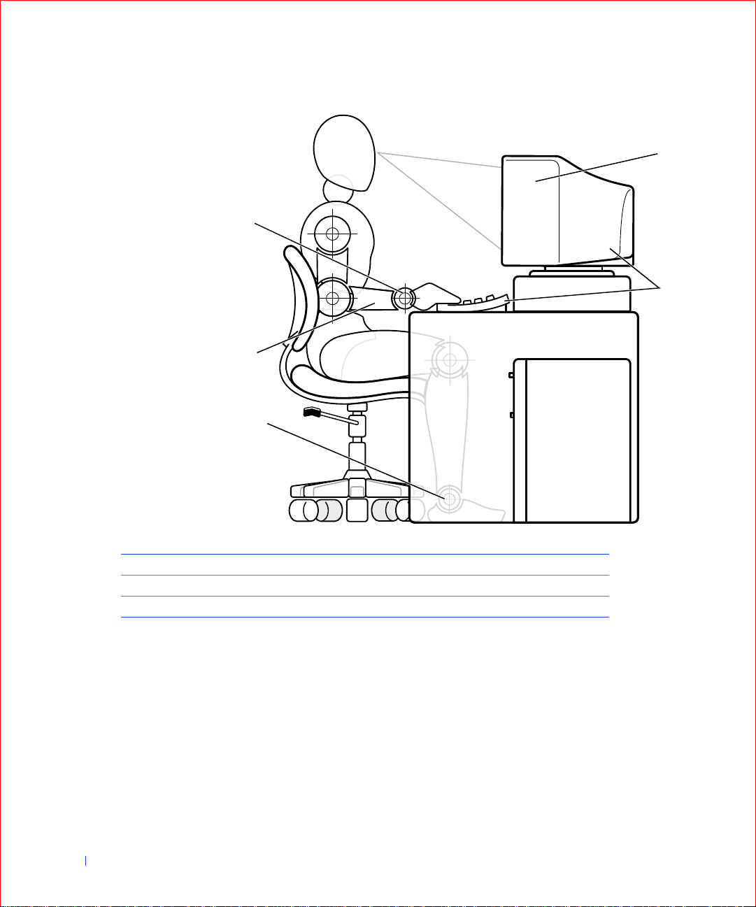
Ergonomic Computing Habits
CAUTION: Improper or prolonged keyboard u se may resul t in
injury.
CAUTION: Viewing the monitor screen for extended periods of
time may result in eye strain.
Page 11

For comfort and efficiency, observe the following ergonomic guidelines
when setting up and using your computer:
• Position your computer so that the monitor and keyboard are directly
in front of you as you work. Special shelves are available (from Dell and
other sources) to help you correctly position your keyboard.
• Set the monitor at a comforta ble viewing distance (u sually 510 to 610
millimeters [20 to 24 inches] from your eyes).
• Make sure the monitor screen is at eye level or slightly lower when you
are sitting in front of the monitor.
• Adjust the tilt of the monitor, its contrast and brightness settings, and
the lighting around you (such as overhead lights, desk lamps, and the
curtains or blinds on nearby windows) to minimize reflections and
glare on the monitor screen.
• Use a chair that provides good lower back support.
• Keep your forearms horizontal with your wrists in a neutral,
comfortable position while using the keyboard or mouse.
• Always leave space to rest your hands while using the keyboard or
mouse.
• Let your upper arms hang naturally at your sides.
• Sit erect, with your feet resting on the floor and your thighs level.
• When sitting, make sure the weight of your legs is on your feet and not
on the front of your chair seat. Adjust your chair’s height or use a
footrest, if necessary, to maintain proper posture.
• Vary your work activities. Try to organize your work so that you do not
have to type for extended periods of time. When you stop typing, try
to do things that use both hands.
13
Page 12
1
5
2
www.dell.com | support.dell.com
4
3
14
1 monitor screen at or below eye level 4 arms at desk level
2 monitor and keyboard positioned directly in front of the user 5 wrists relaxed and flat
3 feet flat on the floor
Page 13

SECTION 1
About Your Computer
Finding Information and Assistance
Front Panel
Back Panel
Inside Your Computer
www.dell.com | support.dell.com
Page 14
Finding Information and Assistance
The following table lists the resources that Dell provides as support tools.
Additional resources may be shipped with your computer system.
Resources and Support Tools
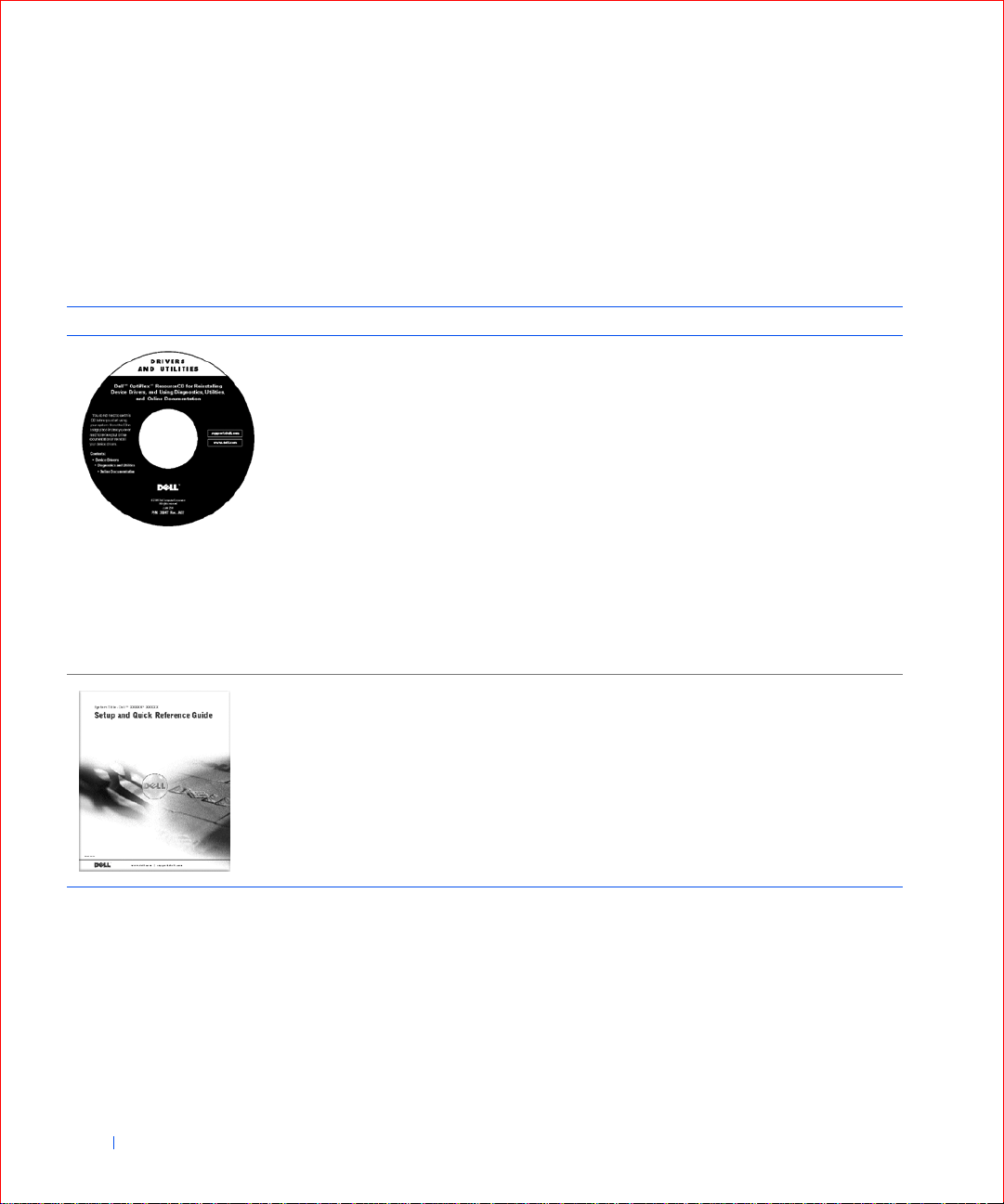
Resources Contents Using the Resource
Dell OptiPlex ResourceCD
•Dell Diagnostics
www.dell.com | support.dell.com
•Drivers
• Utilities
•Computer and device
documentation
Setup and Quick Reference
Guide
• Getting started/setup
• Support tools
• Solving Problems
See the main menu on the ResourceCD that was shipped
with your computer. Use the pull-down menu to make
selections appropriate for your computer . You can perform
the following tasks:
• Diagnose a problem
• Install or reinstall drivers
• Obtain information on your computer and devices
NOTE: User documentation and drivers are already
installed on your computer when shipped from Dell. You
can use this CD to access docume ntation, reinst all drive rs,
or run diagnostics tools. You must boot your computer
from this CD to run the diagnostics, which may require
changing your computer’s boot sequence.
For more information on using the ResourceCD, see
“Using the Dell OptiPlex ResourceCD.”
See the Setup and Quick Reference Guide for information
on the following:
• Setting up your compu ter
• Finding and using support resources
• Diagnosing a problem
• Using tools and utilities
16 About Your Computer
Page 15
Resources and Support Tools
Resources Contents Using the Resource
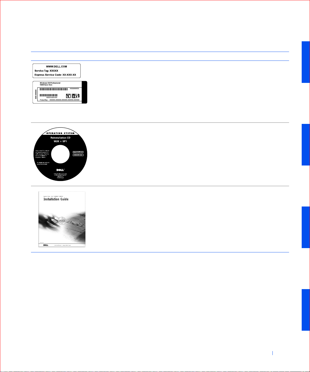
Service and Registration
Labels—located on the front
or side of your Dell™
computer.
• Express Service Code and
• Product Key (also called the
Operating system CD To reinstall your operating sys tem, use the operating
Operating system installatio n
guide
(continued)
The Express Service Code and Service Tag Numbe r are
unique identifiers fo r your Dell computer.
You may need the Product K ey (or P ro duct ID) numbe r to
complete th e o p er ating system set u p.
Service Tag N umber
Product ID or Certificate of
Authenticity [COA])
system CD that was shipped with your co mputer.
NOTE: The operating system CD may not include all the
latest drivers for your computer. If you reinstall your
operating system, use the ResourceCD to reinstall drivers
for the devices shipped with your computer.
For more information about reinstalling your operating
system, see the op erating system installation
documentation that was shipped with your computer.
See the operating system installation guide for
information on reinstalling and configuring your
operating system.
Click the Start button and select Help or Help and
Support, depending on your operating system, to obtain
more information on your operating system.
About Your Computer 17
Page 16

Resources and Support Tools
(continued)
Resources Contents Using the Resource
User’s guides for your
computer and devices
Depending on your operating system, double-click the
User’s Guides icon on your desktop or click the Start
button and then select Help and Support to access the
electronic do c ume ntation stored on your hard dr ive .
Obtain information o n the following:
• Using your computer
User’s Guides
• Configuri ng system settings
• Removing and installing parts
• Installing an d co n f ig u r ing softwar e
www.dell.com | support.dell.com
• Diagnosing a problem
• Technical specifica tions
• Device documentation (on selected operating systems)
• Getting technical assistance
Dell support website
• Technical support and
information
• Downloads for your
computer
•Order or delivery status
• Hints and tips, technology
papers, service information
Go to http://support.dell.com and complete the one-time
registration.
• Get help with general usage, installation, and
troubleshooting questions
• Obtain answers to technical service and support
questions
• Get the latest versions of the drivers for your computer
• Access documentatio n about your computer and
devices
• Join online discussions with other Dell customers and
Dell technical professionals
• Explore a list of online links to Dell's primary vendors
Dell Premier Support website
•Service call status
•Top technical issues by
product
Go to http://premiersupport.dell.com:
The Dell Premier Support website is customized for
corporate, government, and education customers.
This site may not be available in all regions.
• Frequently asked questions
by product number
•Customized service tags
• System co nfiguration detail
18 About Your Computer
Page 17
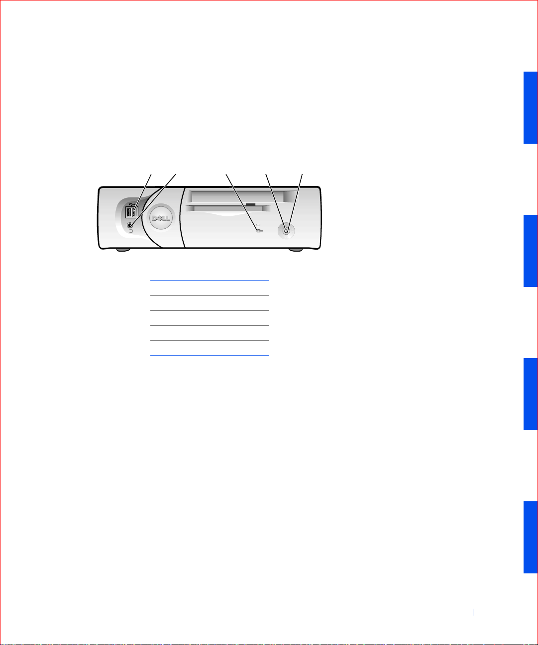
Front Panel
The following figures show the controls, lights, and features located on the
front panel of the small form-factor, small desktop, and small mini-tower
computers.
Small Form-Factor Computer
12 3 4 5
1USB connectors (2)
2 headphone connector
3 hard drive access lights
4 power button
5power light
About Your Computer 19
Page 18
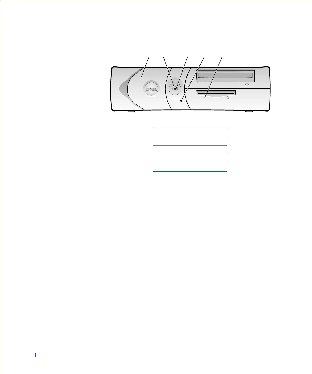
Small Desktop Computer
12 3 4 5
www.dell.com | support.dell.com
1 front panel door
2 power button
3power light
4 hard drive access light
5 floppy drive access light
20 About Your Computer
Page 19
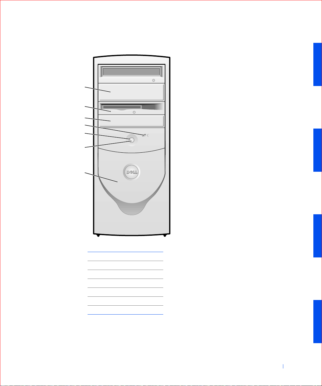
Small Mini-Tower Computer
1
2
3
4
5
6
7
1removable drive panel
2 floppy drive access light
3removable drive panel
4 hard drive acce ss light
5power button
6power light
7 front panel door
About Your Computer 21
Page 20
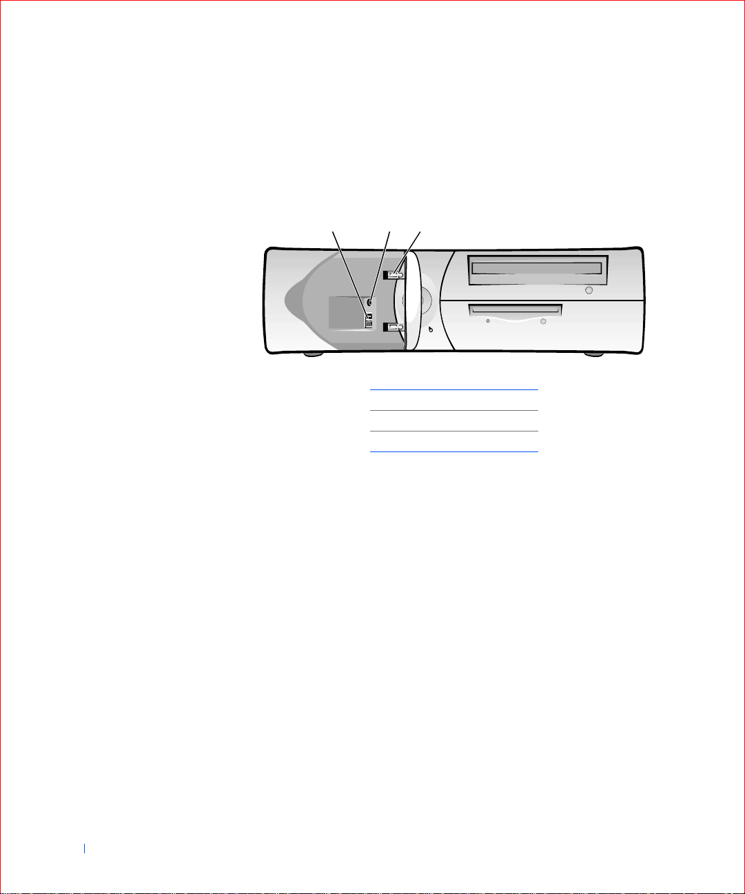
Front Panel Door
Open the front panel door to access two Univers al Serial Bus (USB)
connectors and one headphone connector. This door is removable; if you
remove it or accidentally knock it off its hinges, it snaps back in place.
Small Desktop Computer
213
www.dell.com | support.dell.com
1USB connectors (2)
2 headphone connector
3 breakaway hinges (2)
22 About Your Computer
Page 21
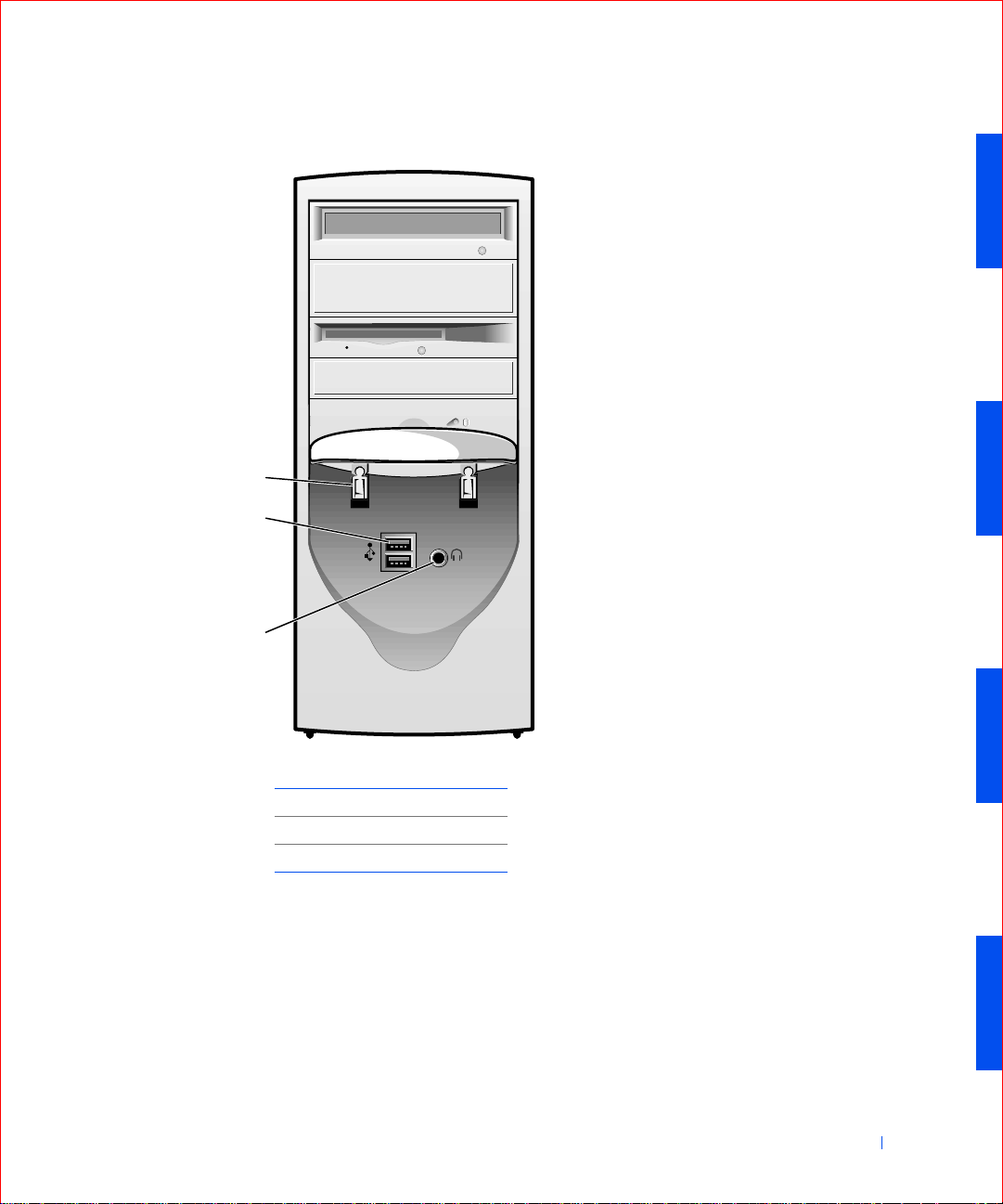
Small Mini-Tower Computer
1
2
3
1 breakaway hinges (2)
2USB connectors (2)
3 headphone connector
Speaker/Headphone Connector
Used to connect computer speakers, headphones, or other audio output
devices. This connector is amplified to support headphones.
Power Button
The power button controls the computer's AC input power.
About Your Computer 23
Page 22

The Microsoft® Windows® 98 Second Edition (SE), Windows 2000, and
Windows XP operating systems let you configure the function of the power
button through the Advanced Configuration and Power Interface (ACPI)
feature, as shown in the following table.
NOTICE: To turn off your computer, perform an orderly computer shutdown
using the operating system menu when possible.
Power Button Functions for Windows 98 SE, Windows 2000,
and Windows XP with ACPI
www.dell.com | support.dell.com
Action Results
Computer Turned On
and ACPI Enabled
Press power
button
Hold power
button
for 6 seconds*
Computer goes into standby mode or
turns off (depending on the operating
system setup)
Computer turns off Computer
Computer
in Standby
Mode
Computer
turns on
turns off
Computer
Turn ed Off
Boots and
computer
turns on
Boots and
computer
turns on
*Pressing or holding the power button to shut down the computer may result in
data loss. Use the power button to shut down the computer only if the operating
system is not responding.
Power Button Functions for Windows 98 SE, Windows 2000,
and Windows XP with ACPI Disabled
Action Results
Computer Turned On
and ACPI Disabled
Press power button Computer turns off
immediately
Hold power button
for 6 seconds*
Computer turns off Computer turns
Computer in
Suspend Mode
Computer turns
off immediately
off
Computer
Turn ed Off
Boots and
computer turns
on
Boots and
computer turns
on
24 About Your Computer
Page 23

*
Pressing or holding the power button to shut down the computer may result in data
loss. Use the power button to shut down the computer only if the operating system is
not responding.
Power Button Functions for Mic rosoft Windows NT®
Action Results
Computer
Tu rne d On
Press power button Computer shuts
down
Hold power button for 6 seconds* Computer turns
off
Pressing or holding the power button to shut down the computer may result in data
*
loss. Use the power button to shut down the computer only if the operating system is
not respon di ng.
Computer Turned Off
Boots and computer turns
on
Boots and computer turns
on
If the computer does not turn off when you press the power button, the
computer may be hung. Press and hold the power button until the
computer turns off completely (this proces s may take sever al seconds). If
the computer is hung and the power button fails to function properly,
unplug the AC power cable from the computer, wait for it to completely
stop running, and plug in the AC power cable. If the computer does not
restart, press the power button to restart the computer.
Power Light
The power light illuminates in two colors and blinks or remains solid to
indicate different states (normal and nonnormal). The following ar e normal
lights:
• No light — computer is in the off state (S4, S5, or mechanical OFF)
• Steady green — normal operating s tate
• Blinking green — low-po wer state (S1 or S3)
About Your Computer 25
Page 24
NOTE: Your computer
can resume from the S3
state (suspend to RAM) in
several ways. Pressing the
power button always
works. Remote Wake Up
also creates an S3 wake
event if enabled in system
setup and in your
operating system.
Personal System/2 (PS/2)
wake events also var y
depending on your
www.dell.com | support.dell.com
operating system, but
PS/2 mice always wake
the computer from S3
with both movement and
click. Certain USB
devices also wake the
computer from S3, and
the action required varies
by device. Check your
device documentation for
details.
See “Diagnostic Lights” for a description of nonnormal indications.
Floppy Drive Access Light
The floppy drive access light lights when the drive is reading data from, or
writing data to, a floppy disk. Wait until this light turns of f before you
remove the floppy from the drive.
Hard Drive Access Light
The hard drive access light lights when the computer is reading data from,
or writing data to, the drive.
Back Panel
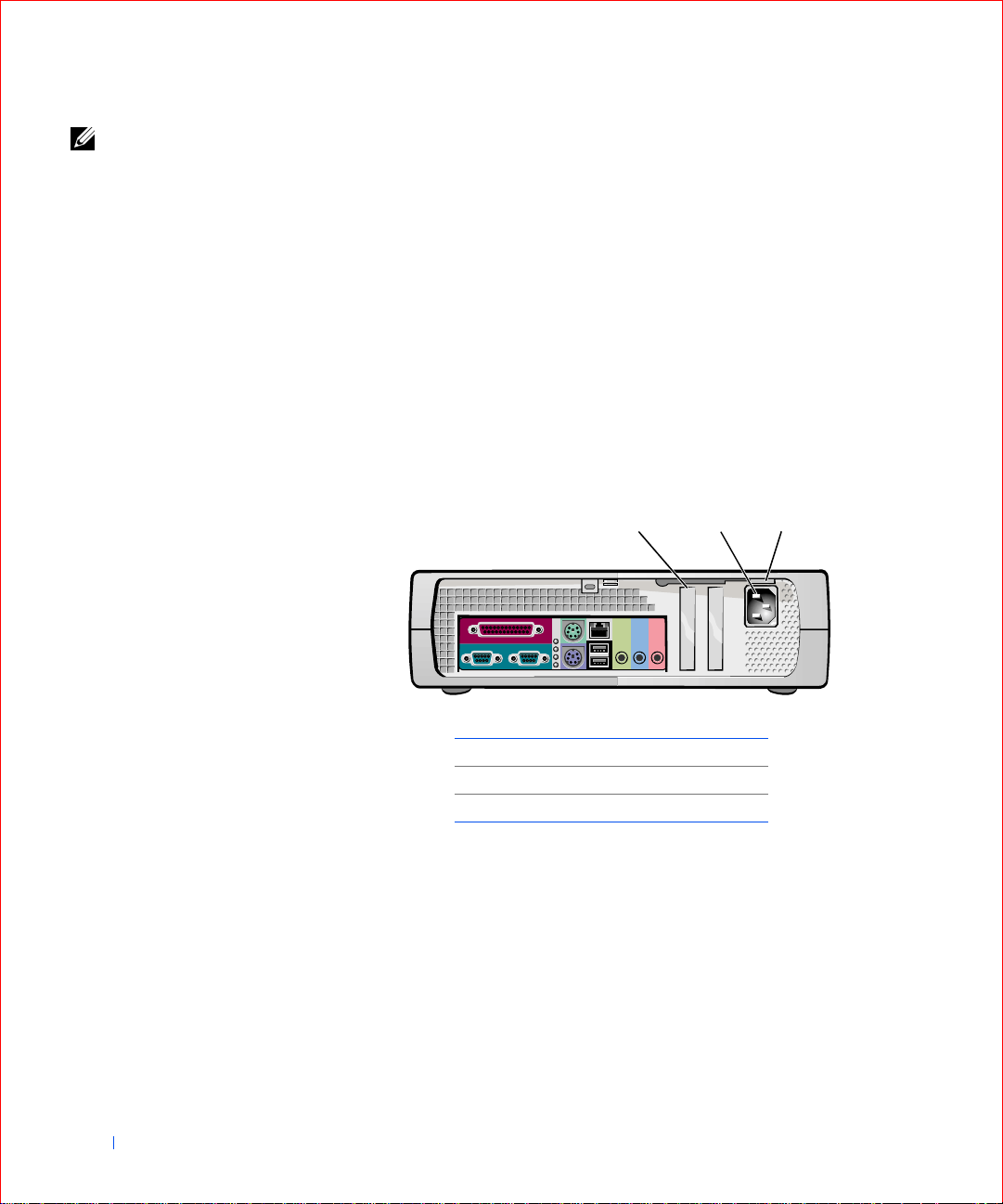
Small Form-Factor Computer
213
26 About Your Computer
1 half-height PCI expansion-card slot
2 AC adapter
3AC voltage switch
Page 25
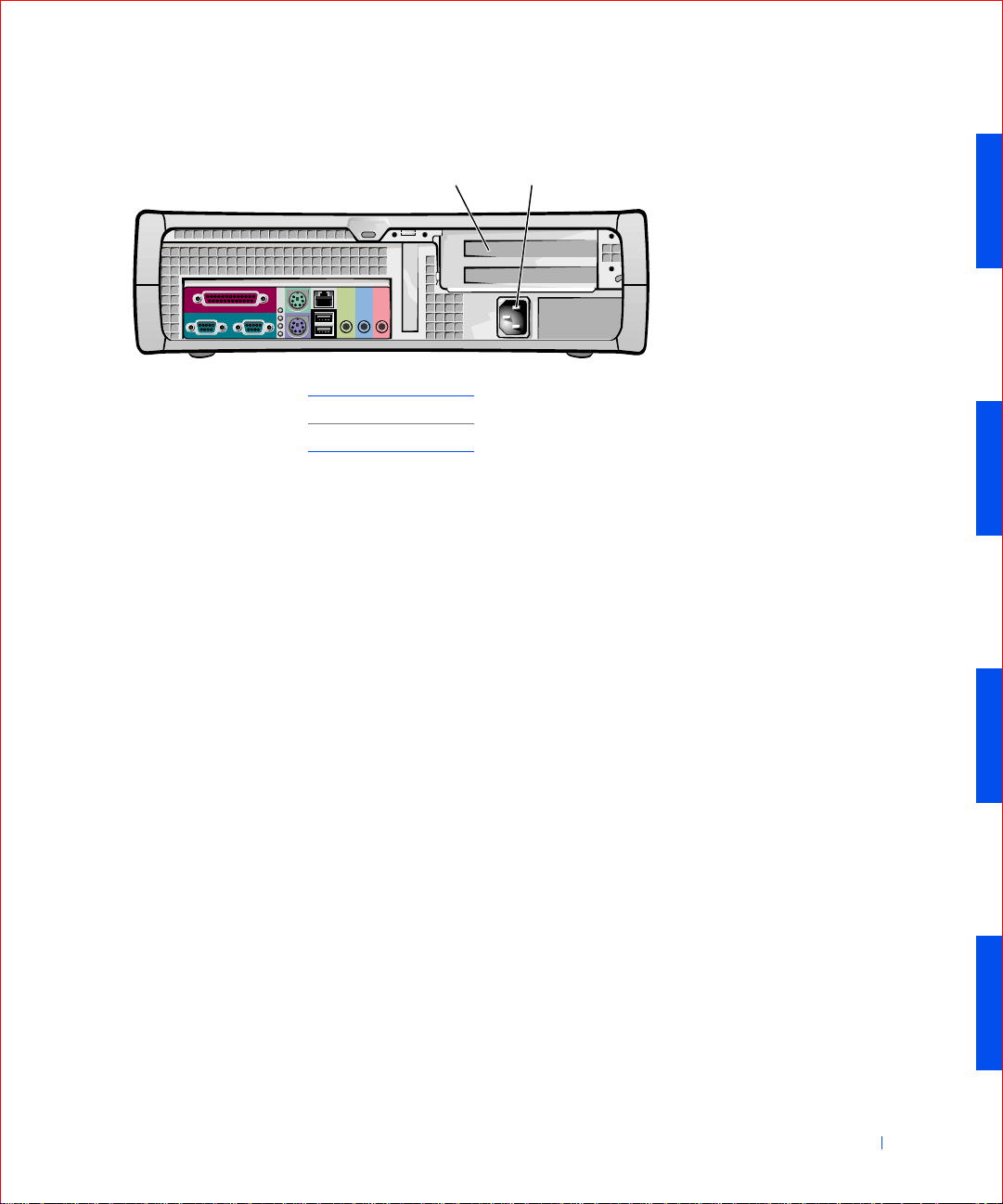
Small Desktop Computer
1PCI slots (2)
2 AC adapter
21
About Your Computer 27
Page 26
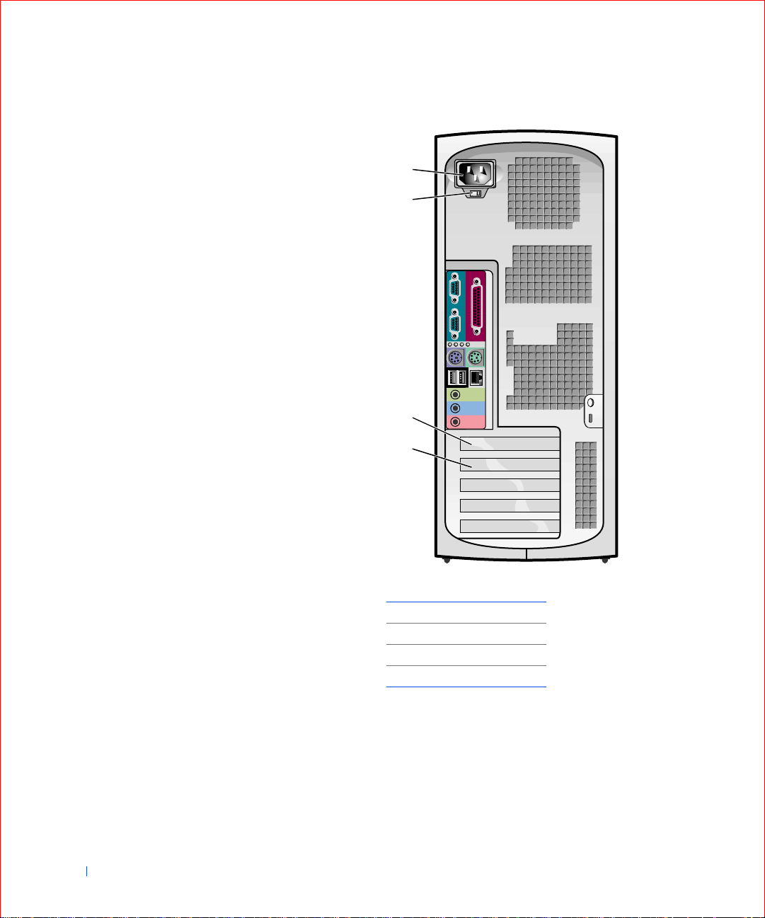
Small Mini-Tower Computer
1
2
www.dell.com | support.dell.com
3
4
28 About Your Computer
1AC adapter
2AC voltage switch
3AGP slot
4PCI slots (4)
Page 27
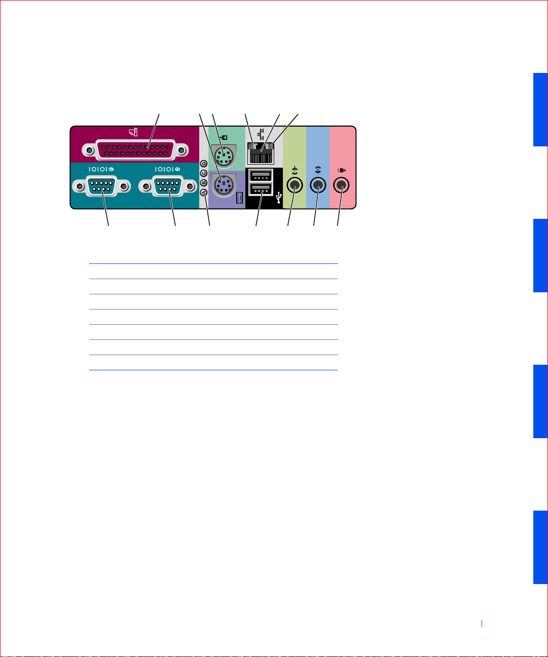
I/O Panel—Small Form-Factor, Desktop, and Mini-Tower
Computers
213456
789101211 13
1 parallel connector 8 serial connector (2)
2 keyboard connector 9 diagnostic lights
3 mouse connector 10 USB connectors (2)
4 link integrity light 11 audio line-out connector
5 network adapter 12 audio line-in connector
6 activity light 13 microphone connecto r
7serial connector (1)
Connecting Devices
When you connect external devices to your computer's back panel, follow
these guidelines:
• Check the documentation that accompanied the device for specific
installation and configuration instructions.
For example, you must connect most devices to a particular
input/output (I/O) connector to operate properly. Also, external
devices like a mouse or printer usually require you to load device
drivers into computer memory before they will work.
• Always attach external devices while your computer is turned off. Then
turn on the computer before turning on any external devices, unless
the documentation for the device specifies otherwise. (If the computer
does not seem to recognize the device, try turning on the device before
turning on the computer.)
About Your Computer 29
Page 28

NOTICE: When you disconnect external devices from the back of the
computer, wait 10 to 20 seconds after turning off the computer before you
disconnect any devices to avoid possible damage to the system board.
Parallel Connector
This is used to connect printers. Default designation is LPT1.
NOTE: The integrated
parallel connector is
automatically di sabled if
the computer detects an
installed expansion card
www.dell.com | support.dell.com
containing a parallel
connector configured to
the same address as
specified in “Additional
System Setup Options.”
NOTE: USB mice will
only wake the computer
from the S1 (standby) and
S3 (suspend to RAM)
states with a click.
Mouse Connector
Turn off the computer and any attached devices before connecting a mouse
to the computer. If your computer uses Microsoft Windows
Windows NT 4.0, Dell installed the necessary mouse drivers on your hard
drive.
2000 or
USB Connectors
These are used to attach USB-compliant devices such as keyboards, mice,
printers, and computer speakers to your computer.
Integrated Network Adapter Connector
The network adapter, which includes a Remote Wake Up feature, has the
following lights:
• A yell ow network activity light flashes when the computer is
transmitting or receiving network data. (A high volume of network
traffic may make this light appear to be in a steady “on” state.)
• A dual-colored link integrity light, which is green when a good
connection exists between a 10-megabit per second (Mbps) network
and the computer , or is orange when a good connection exists between
a 100-Mbps network and the computer. W h en the light is off, the
computer is not detecting a physical connection to the network.
30 About Your Computer
Network Cable Requirements
The network adapter connector attaches an unshielded twisted pair (UTP)
Ethernet cable to your computer. Pr ess one end of the UTP cable to an RJ45
jack wall plate or to an RJ45 port on a UTP concentrator or hub, depending
on your network configuration, and press the other end of the UTP cable
into the network adapter connec tor until the cable snaps securely into place
Dell recommends the use of Category 5 wiring and connectors for our
customers’ networks.
Page 29

Line-In Jack
This jack is used to attach record/playback devices such as cassette players,
CD players, and VCRs. Connect the line-out cable from any of these
devices to the line-in jack.
Line-Out Jack
This jack is used to attach computer speakers. This jack is amplified, so
speakers with integrated amplifiers are not required. Connect the audio
cable from the speakers to this jack.
Microphone Jack
This jack is used to attach a standard personal computer microphone.
Connect the audio cable from the microphone to the microphone jack.
Serial Connectors
Default port designations: COM1 for port 1 and COM2 for port 2. You can
reassign the serial connector’s designation if you add an expansion card
containing a serial connector using this designation.
If you set the computer’s serial connectors to Auto in system setup and add
an expansion card containing a serial connector configured to a specific
designation, the compute r automatically maps (assigns ) the integrated
ports to the appropriate COM setting as necessary.
Before you add a card with a serial connector, check the documentation that
accompanied your software to make sure that the software can be mapped
to the new COM port designation.
Keyboard Connector
Attach the keyboard cable to the 6-pin connector on the back panel.
About Your Computer 31
Page 30
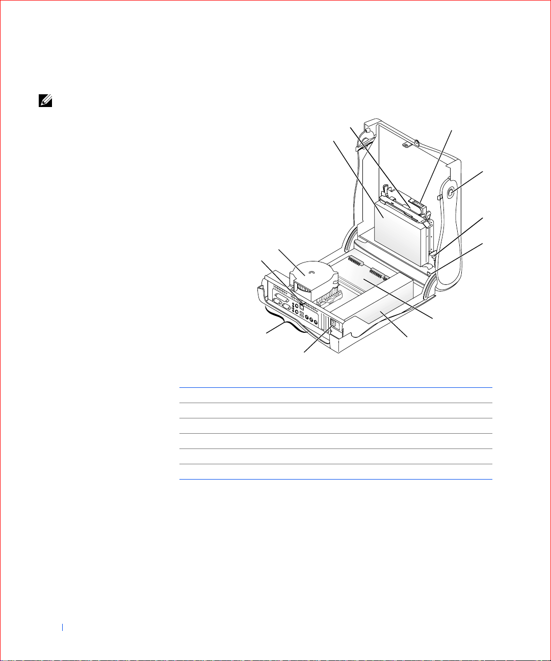
Inside Your Computer
NOTE: User service
access points are colorcoded green.
www.dell.com | support.dell.com
Small Form-Factor Computer
2
1
12
11
7
10
9
1 hard drive 7 system board
2 3.5-inch floppy drive 8 power supply
3 CD/DVD drive 9 AC power connector
4 cover release buttons (2) 10 I/O ports and connectors
5 internal speaker 11 padlock ring
6 chassis intrusion switch 12 heat sink and blowe r assembly
8
3
4
5
6
32 About Your Computer
Page 31
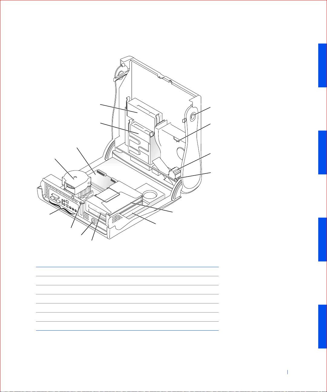
Small Desktop Computer
14
13
12
11
10
9
8
7
1 cover release buttons (2) 8 AC power connector
2 hard drive 9 padlock ring
3 internal speaker 10 I/O ports and connectors
4 chassis intrusion switch 11 heat sink and blower assembly
5 expansion-card cage 12 system board
6 power supply 13 3.5-inch floppy drive
7 expansion-card slots 14 CD/DVD drive
5
6
1
2
3
4
About Your Computer 33
Page 32

Small Mini-Tower Computer
13
1
2
12
www.dell.com | support.dell.com
11
10
3
9
4
8
5
7
6
1 cover release buttons (2) 8 AC power connector
2 hard drive 9 padlock ring
3 internal speaker 10 microprocessor and airflow shroud
4 chassis intrusion switch 11 power supply
5 system board 12 3.5-inch floppy drive
6 expansion-card slots 13 CD/DVD drive
7 I/O ports and connectors
34 About Your Computer
Page 33

Cable Colors
Hard drive Blue
Floppy drive Black
CD/DVD drive Orange
USB Gray
ATA or IDE Green
Control panel Yellow
CD audio Blue
Computer audio Black
About Your Computer 35
Page 34

System Board Components
The following figure shows the principal connectors and components on the
system board.
1
23 4 5
30
29
www.dell.com | support.dell.com
28
27
26
25
24
6
7
8
9
10
11
12
36 About Your Computer
14162223
13151718192021
Page 35

1 floppy drive 16 audio line-out conn e ct o r
2 internal speaker 17 12-volt microprocessor powe r connector
3 EIDE2 connector 18 network (upper) and USB connectors (2) (lower)
4 front panel connector 19 keyboard (lower) and mouse (upper) connectors
5 EIDE1 connector 20 diagnostic lights
6 suspend-to-RAM light 21 serial 2 connector
7 PCI riser (small mini-tower computer only) 22 parallel connector
8 standby power light 23 serial 1 connector
9 AGP connector 24 microprocessor and heat sink
10 PCI connectors 25 memory module (DIMM) connectors
11 CD audio connector 26 fan connector
12 telephony con nector (TAPI) 27 main power connector
13 front audio connector 28 battery
14 microphone co nnector 29 RTC reset jumper
15 audio line-in connector 30 password jumper
About Your Computer 37
Page 36

System Board Labels
Connector or Socket Description
AUDIO Line-in, line-out, and microphone jacks
AUX_PWR Standby power light
BATTERY Battery socket
STR Suspend-to-RAM light
CD_IN CD drive audio cable connector
DIAG_LED Diagnostic lights
www.dell.com | support.dell.com
DIMM A and DIMM B Dual in-line memory module (DIMM) sockets
DSKT Floppy drive interface connector
FAN Microprocessor fan connector
FRONTAUDIO Front panel audio connector for onboard audio
FRONTPANEL Front panel cable connector
IDE1 Primary IDE interface connector
IDE2 Secondary IDE interface connector
KYBD_MOUSE Keyboard and mouse connectors
CPU Microprocessor connector
MODEM Telephony connector
NIC_USB Integrated network adapter connector and USB
connectors
PA R_SER1_SER2 Parallel and serial connectors
PCI1, PCI2, PCI3, and
PCI expansion card connectors
PCI4
POWER Main power input connector
12VPOWER 12-volt power connector
PSWD P asswor d jumper
RTCRST RTC reset jumper
H_RISER Horizontal riser board connector; vertical PCI cards
V_RISER Vertical riser board connector; horizontal PCI cards
SPEAKER Internal speaker
38 About Your Computer
Page 37

SECTION 2
Advanced Features
LegacySelect Technology Control
Manageability
Security
Password Protection
Computer Settings
Additional System Setup Options
Jumper Settings
Software Installation and Configuration
www.dell.com | support.dell.com
Page 38

LegacySelect Technology Control
LegacySelect technology control permits the deployment of legacy full,
legacy reduced, or legacy free solutions based on a common platform with
common hard drive images and common help desk procedures. Control is
provided to the administrator through the system setup program , Dell
OpenManage™ IT Assistant, or Dell custom factory integration.
LegacySelect allows the administr ator to electronically activate or
deactivate specific connectors and media devices including: serial and USB
connectors, parallel connector, floppy drive, PCI slots, and PS/2 mouse.
When the connectors and media devices are deactivated, resources that
www.dell.com | support.dell.com
they might have used are available. Any changes that are made will take
place after you reboot the computer.
Manageability
Dell OpenManage™ IT Assistant
Dell OpenManage IT Assistant is the premier Dell™ systems management
application for configuring, managing, and monitoring computers and other
devices on a corporate network. IT Assistant employs the latest remote
management technology to provide asset management, configuration
management, event (alert) management, and security management for
systems equipped with industry-standard management software. Software
of this type is called system management instrumentation.
40 Advanced Features
IT Assistant supports instrumentation that conforms to the following
industry standards:
• Simple Network Management Protocol (SNMP)
• Desktop Management Interface (DMI)
• Common Information Model (CIM )
The instrumentation available for your computer is Dell OpenManage
Client instrumentation, which is based on DMI and CIM. For more
information on IT Assistant, see the Dell OpenManage IT As sistant User’s
Guide available on the Dell website.
Page 39

Dell OpenManage Client Instrumentation
Dell OpenManage Client Instrumentation is software that enables remote
management application programs such as IT Assistant to do the following:
• Access information about your computer , such as how many processors
it has and what operating system it is running
• Monitor the status of your computer, such as listening for thermal
alerts from temperature probes or hard drive failure alerts from storage
devices
• Change the state of your computer, such as updating its BIOS or
shutting it down remotely
Dell OpenManage Client Instrumentation can be installed on computers
like yours, which, when set up on a network with IT Assistant, are called
managed systems. For more information about Dell OpenManage Client
Instrumentation, see the Dell OpenManage Client Instrumentation User’s
Guide available on the Dell website.
Security
The computer provides the following methods of phys i c ally securing the
chassis:
• Chassis Intrusion Detection
• Padlock Ring and Security Cable Slot
Chassis Intrusion Detection
The chassis intrusion monitor can detect when the chassis is opened. The
Chassis Intrusion option in system setup displays the status of the monitor.
1 Enter system setup.
2 Press the down-arrow keys to move to the System Security option.
3 Press <Enter> to access the System Security option's pop-up menu.
4 Press the down-arrow keys to move to the Chassis Intrusion option.
5 Press the spacebar to select an option setting.
Advanced Features 41
Page 40

Option settings:
• Enabled — When the computer cover is opene d with this setting, a
DMI event is generated, th e setting changes to Detected, and the
following message appears during the boot routine at the next
computer start-up:
Alert! Cover was previously removed.
To reset the Detected setting, enter system setup during the
computer's power-on self-test (POST). In the Chassis Intrusion
option, press the left- or right-arrow key to select Reset, and then
choose Enabled, Enabled-Silent, or Disabled.
www.dell.com | support.dell.com
• Enabled-Silent (default) — When the computer cover is opened with
this setting, a DMI event is generated and the setting changes to
Detected, but the alert message does not appear during the boot
sequence at the next computer start-up.
• Disabled — No intrusion monitoring occurs and no messages appear.
NOTE: When the setup password is enabled, you must know the setup
password before you can reset the Chassis Intrusion option.
Padlock Ring and Security Cable Slot
Use one of the following methods to secure your computer:
• Use a padlock alone or a padlock and looped security cable with t he
padlock ring.
A padlock alone prevents the computer from being opened.
A security cable looped around a stationary object and used in
conjunction with the padlock can help prevent the unauthorized
movement of the computer.
• Atta c h a commercially available antitheft devi ce to the security cable
slot on the back of the computer to prevent the unauthorized
movement of the computer.
Antitheft devices usually include a segment of metal-stranded cable
with an attached locking device and key. Dell recommends that you
use a Kensington lock. For instructions on installing this kind of
antitheft device, see the documentation that accompanied the device.
42 Advanced Features
Page 41

Password Protection
The computer provides two types of password protec tion:
•System Password
•Setup Password
System Password
System passwords allow only those who know the password to have full use
of the computer. Yo ur Dell computer does not have the system password
feature enabled when you receive it
NOTICE: Although passwords provide security for the data on your computer,
they are not foolproof. If your data requires more security, it is your
responsibility to ob ta in and use additional forms of protection, such as data
encryption programs.
NOTICE: If you leave your computer running and unattended without having
a system password assigned, or if you leave your computer unlocked so that
someone can disable the password by changing a jumper setting , anyone can
access the data stored on your hard drive.
System Password settings in system se tup:
• Enabled — a system password is assigned
• Disabled — system password feature is disabled by a jumpe r setting on
the system board
NOTE: Before you
purchase an antitheft
device, make sure it
works with the security
cable slot on your
computer.
• Not Enabled — no system password is assigned and the password
jumper on the system board is in the enabled position (its def ault
setting)
Assigning a System Password
1 Verify that Password Status is set to Unlocked.
2 Highlight System Password and then press the left- or right-arrow key.
The option heading changes to Enter Password, followed by an empty
32-character field in square brackets.
3 Type your new system password.
You can use up to 32 characters.
NOTE: You cannot
change or enter a new
system password if either
of these options is
displayed.
NOTE: You can only
assign a system password
when System Password is
set to Not Enabled.
Advanced Features 43
Page 42

As you press each character key (or the spacebar for a blank space), a
placeholder appears in the field. The password assignment operation
recognizes keys by their location on the keyboard, without
distinguishing between lowercase and uppercase characters. For
example, if you have an M in your password, the computer recognizes
either M or m as correct.
Certain key combinations are not valid. If you enter one of these
combinations, the speaker emits a beep.
To erase a character when entering your password, press <Backspace>
or the left-arrow key.
NOTE: To escape from
www.dell.com | support.dell.com
the field without assigning
a system password, press
<Tab> or the
<Shift><Tab>
combination to move to
another field, or press
<Esc> at any time prior
to completing step 5.
Press <Ente r> .
4
If the new system password is less than 32 characters, the whole field
fills with placeholders. Then the option heading changes to Verify
Password, followed by another empty 32-character field in square
brackets.
5 To confirm your password, type it a second time and press <Enter>.
The password setting changes to Enabled. Your system password is
now set; you can exit system setup and begin using your computer.
Password protection takes effect when you reboot the computer by
turning the computer off and then on again.
Using Your System Password
When you turn on your computer, or whe n you reboot the computer by
pressing the <Ctrl><Alt><Del> combination, the following prompt
appears on the screen when Password Status is set to Unlocked:
Type in the password and
- press <ENTER> to leave password security enabled.
- press <CTRL><ENTER> to disable password security.
Enter password:
If Password Status is set to Locked, the following prompt appears:
Type the password and press <Enter>.
NOTE: If you have
assigned a setup
password, the computer
accepts your setup
password as an alternate
system password.
44 Advanced Features
If you enter a wrong or incomplete system password, the following message
appears on the screen:
** Incorrect password. **
Enter password:
Page 43

If you again enter an incorrect or incomplete system password, the same
message appears on the screen. The third and subsequent times you enter
an incorrect or incomplete system password, the computer displays the
following message:
** Incorrect password. **
Number of unsuccessful password attempts: 3
System halted! Must power down.
Even after your computer is turned off and on, the previous message is
displayed each time an incorrect or incomplete system password is entered.
Deleting or Changing an Existing System Password
To delete or change an existing system password, perform the following
steps:
1 Enter system setup program, and verify that Password Status is set to
Unlocked.
2 Reboot your comput e r t o forc e it t o prom pt y o u fo r a sy st em password.
3 When prompted, type the system password.
4 Press <Ctrl><Enter> to disable the existing system password,
instead of pressing <Enter> to continue with the normal operation of
your computer.
5 Confirm that Not Enabled is displayed for the System Password
option.
If Not Enabled appears in the System Password option, the system
password has been deleted. If you want to assign a new password,
continue to step 6. If Not Enabled is not displayed for the System
Password option, press <Alt><B> to reboot the computer, and then
repeat steps 3 through 5.
6 To assign anew password, follow the procedure in “Assigning a System
Password.”
NOTE: You can use
Password Status in
conjunction with System
Password and Setup
Password to further
protect your computer
from unauthoriz e d
changes.
Setup Password
Setup passwords allow only those who know the password to have full use of
system setup. Your Dell computer does not have the setup password feature
enabled when you receive it.
Setup Password options in system setup:
Advanced Features 45
Page 44

www.dell.com | support.dell.com
NOTE: The setup
password can be the same
as the system password.
• Enabled — does not allow assignment of setup passwords; users must
enter a setup password to make changes to system setup
• Not Enabled — allows assignment of setup passwords; password
feature is enabled but no password is assigned
Assigning a Setup Password
1 Enter syste m setup, and ve rify that Setup Password is set to Not
Enabled.
2 Highlight Setup Password and press the left- or right-arrow key.
The computer prompts you to enter and verify the password. If a
character is illegal for password use, the computer emits a beep.
3 Type in and then verify the password.
After you verify the password, the Setup Password setting chan ges to
Enabled. The next time you attempt to enter system setup, the
computer prompts you for the setup password.
NOTE: If the two
passwords are different,
the setup password can be
used as an alterna te
system password.
However, the system
password cannot be used
in place of the setup
password.
NOTE: You can use
Password Status in
conjunction with Se tup
Password to protect the
system password from
unauthorized chan ges.
46 Advanced Features
A change to Setup Password becomes effective immediately (rebooting the
computer is not required).
Operating Your Computer With a Setup Password Enabled
When you start system setup, the Setup Password option is highlighted,
prompting you to type the pa ssword.
If you do not enter the correct password, the computer lets you view, but
not modify, system setup options.
Deleting or Changing an Existing Setup Password
To change an existing setup password, you must know the setup password.
1 Enter system setup.
2 If you have already assigned a setup password, type it at the prompt.
3 Highlight Setup Password and press the left- or right-arrow key to
delete the existing setup password.
The setting changes to Not Enabled.
Page 45

4 If you want to assign a new setup password, perform the steps in
“Assigning a System Password.”
Disabling a Forgotten Password
NOTICE: This process erases both the system and setup passwords.
CAUTION: Before you open the computer cov er, see “Safety
First—For You and Your Computer.”
1
Open the computer cover.
2 Remove the jumper plug from the PSWD jumper to disable the
password feature.
See “Jumper Settings” to locate t he pa ssword jumper (labeled
“PSWD”) on the system board.
3 Close the computer cover.
4 Reconnect your computer and devices to an electrical outlet, and then
turn them on.
This erases the existing password(s).
5 Enter system setup and verify that the pa ssword is disabled. P roceed t o
step 6 if you want to assign a new password.
CAUTION: Before you open the computer cov er, see “Safety
First—For You and Your Computer.”
Open the computer cover.
1
2 Replace the PSWD jumper plug.
3 Close the computer cover and reconnect the computer and devices to
an electrical outlet and turn them on.
Booting your computer with the PSWD jumper installed reenables the
password feature. When you enter system setup, both password
options appear as Not Enabled, meaning that the password fe ature is
enabled but that no password is assigned.
4 Assign a new system and/or setup password.
NOTE: B efore you assign
a new system and/or setup
password, you must
replace th e PSWD jumpe r
plug to reenable the
password feature.
Advanced Features 47
Page 46

Computer Settings
Each time you start your computer, it compares the installed hardware with
the computer configuration information stored in nonvolatile random
access memory (NVRAM). If the computer detects a discrepancy, it
generates an error messages for each incorrect configuration setting.
You can use computer settings as follows:
• To set user-selectable options such as date and time, or system
password
• To read the current amount of memory or set the type of hard drive
www.dell.com | support.dell.com
installed
You can view the current settings at any time. Dell recommends that you
print the system setup screens (by pressing <Print Screen>) or record the
information for future reference.
Before you use system setup, you need to know the kind of floppy drive(s)
and hard drive(s) installed in your computer. If you are unsure of this
information, see the Manufacturing Test Report that was shipped with your
computer and is located in the Dell Accessories folder.
Entering System Setup
48 Advanced Features
1 Turn on (or restart) your computer.
2 When Press <F2> to Enter Setup appears in the upper-right
corner of the screen, press <F2> immediately.
If you wait too long and the Microsoft
appears, continue to wait until you see the Windows desktop. Then
shut down your computer and try again.
NOTE: To ensure an orderly computer shutdown, consult the
documentation th at accompanied your opera ting system.
®
Windows® Windows logo
System Setup Screens
The system setup screens display the current configuration information for
your computer. Information on the screen is organized into four areas:
• Title — the box at the to p of all screens lists the computer name.
Page 47

• Computer data — two boxes below the title box that display your
computer processor, level 2 (L2) cache, service tag, and the version
number of the basic input/out put sy ste m (BIOS)
• Options — a scrollable box listing options that define the
configuration of your computer, including installed hardware, power
conservation, and security features.
Fields to the right of the option titles contain settings or values. Those
you can change appear bright on the screen. Those you cannot change
(because they are set by the computer) appear less bright. When
<Enter> appears to the right of an option title, press <Enter> to
access a popup menu of additional options.
• Key functions — a line of boxes across the bottom of all screens that
lists keys and their functions within system setup.
• Help — press <F1> for information in the currently highlighted
option.
System Setup Navigation Keys
Keys Actio n
or
Moves to the nex t field.
or
or
or
Moves to the pr evious field.
Cycles thr ough th e opt ions in a fie ld. In many field s, you
can also type the appropriate value.
Scrolls through help information.
Enters the selected field's pop-up options men u.
Advanced Features 49
Page 48

Keys Actio n
spacebar or
In the selected field's pop-up options menu, cycles
through the options in a field.
or
Exits system setup without rebooting the system and
returns the system to the boot routine.
Exits system setup and reboots the system,
implementing any ch a nge s yo u ha ve mad e .
www.dell.com | support.dell.com
Resets the selected option to its default setting.
50 Advanced Features
Page 49

Changing the Boot Sequence During System Setup
1 Turn on your computer.
If your computer is already on, restart it.
2 When F2 = Setup appears in the upper-right corner of the screen,
press <Ctr><Alt><F8>.
The Boot Device Menu appears.
Option settings:
• Norma l — The computer a tt empts to boot from the sequence of
devices specified in system setup.
• Diskette Drive — The computer attempts to boot from the floppy
drive. If the computer finds a floppy in the drive that is not bootable,
an error message will appear. If no floppy is in the drive, an error
message appears.
NOTE: This feature
changes the boot sequence
for one time only. On the
next start-up, the
computer boots according
to the devices specified in
system setup. This is
helpful when you need to
change the boot devices
quickly. For example, you
can cause the computer to
boot from the CD drive to
run the Dell Diagnostics,
but the computer boots
from the hard drive when
the diagnostic tests are
complete.
NOTE: If you wait too
long and the Windows
logo appears, continue to
wait until you see the
Windows desktop. Then
shut down your computer
and try ag ain.
• Hard Drive — The computer attempts to boot from the primary hard
drive. If the computer does not find an operating system on the drive,
an error message appears.
• IDE CD Drive — The computer attempts to boot from the IDE CD
drive. If the computer does not find a CD in the drive or if there is not
an operating system on the CD, an error message appears.
Changing the Boot Sequence in System Setup
1 Enter system setup.
Advanced Features 51
Page 50

2 Use the arrow keys to highlight the Boot Sequence menu option and
press <Enter> to access the pop-up menu.
NOTE: Write down your current boot sequence in case you want to
restore it.
Press the up- and down-arrow keys to move through the list of devices.
3
4 Press the spacebar to enable or disable a device (enabled devices
appear with a check mark).
5 Press plus (+) or minus (–) to move a selected device up or down the
list.
Option settings:
www.dell.com | support.dell.com
• Diskette Drive — The computer attempts to boot from the floppy
drive. If the computer finds a floppy in the drive that is not bootable,
an error message appears. If no floppy is in the drive, the computer
attempts to boot from the next device in the list.
• Hard Drive — The computer attempts to boot from the primary hard
drive. If the computer does not find an operating system on the drive,
it attempts to boot from the next device in the list.
• CD Drive — The computer attempts to boot from the CD drive. If
the computer does not find a CD in the dr ive or if there is not an
operating system on the CD, the computer attempts to boot from the
next device in the list.
52 Advanced Features
• MBA — The system prompts you to press <Ctrl><Alt><b> at the
Dell logo screen during b oot . A menu ap pe ars t hat allo ws you to select
a method for booting from a network server. If a boot routine is not
available from the network server, the system attempts to boot from
the next device in the list.
Additional System Setup Options
• AC Power Recovery determines what happens when AC power is
restored to the computer.
When Off is selected, the computer remains off when AC power is
restored. When On is selected, the computer starts up when AC power
is restored.
When Last is selected, the computer returns to the AC power state
existing at the time that AC power was lost. If the computer is on
Page 51

when AC power is lost, the computer starts up when AC power is
restored. If the computer is off when AC power is lost, the computer
remains off when AC power is restored.
• Asset Tag displays the customer-programmable asset tag number for
the computer if an asset tag number is assigned. You can use the Asset
Tag utility, which is included with your software support utilities, to
enter an asset tag number up to ten characters long into nonvolatile
random-access memory (NVRAM).
• Auto Power On allows you to s et t he ti me an d da ys of the wee k to t urn
on the computer automatically. You can set Auto Power On to turn on
the computer either every day or every Monday through Friday.
NOTE: This feature does not work if you turn off your computer using a
power strip or surge protector.
Time is kept in a 24-hour format (hours:minutes). To change the startup time, press the right-arrow key to increase the number in the
highlighted field or press the left-arrow key to decrease the number. If
you prefer, you can type numbers in both the date an d time fields.
The default for Auto Power On is Disabled.
• CPU ID provides the manufacturer's identification code for the
installed microprocessor.
• CPU Information
– CPU Speed indicates the processor speed at which your computer
boots.
Press the left- or right-arrow key to toggle the CPU Speed option
between the resident microprocessor's rated speed (the default)
and a lower compatibility speed, which lets you accommodate
speed-sensitive application programs. A change to this option
takes effect immediately (rebooting the computer is not required).
To toggle between the rated processor speed and the compatibility
speed while the computer is running in real mode, press
<Ctrl><Alt><\>. (For keyboards that do not use American
English, press <Ctrl><Alt><#>.)
– Bus Speed indicates the sp eed of the microprocesso r's sys tem bus,
or front-side bus (FSB).
– Pro c essor ID provides the manufacturer's identification code(s)
for the installed microprocessor.
Advanced Features 53
Page 52

– Clock Speed indicates the core speed at which the
microprocessor(s) operates.
– Cache Size displays the size of the microprocessor's le vel 2 (L2)
cache.
• Diskette Drive A identifies the type of floppy drives installed in your
computer. With the standard cabling configuration, Diskette Drive A
(the boot floppy drive) is the 3.5-inch floppy drive installed in the top
externally accessible drive bay.
The Diskette Drive A option has the following possible settings:
– 3.5 Inch, 1.44 MB
www.dell.com | support.dell.com
– Not Installed
NOTE: Tape drives are not reflected in the Diskette Drive A option. For
example, if you hav e a sing le flo ppy drive an d a tap e drive attac hed to the
floppy drive interface cable, set Diskette Drive A to match the
characteristics of the floppy drive.
• Fastboot allows your computer to boot in 10 seconds or less. The
default setting is On. If you do not want your computer to skip certain
configurations and tests during boot, you may set this option to Off.
• Integrated Devices. This option configures the following devices
integrated with the system board:
Press <Enter> to configure these options as explained in the
following subsections.
– Sound determines whether the integrated audio controller is On
or Off. The default is On.
– USB Controller enables or disables the onboard USB controller.
The onboard USB controller is always enabled during the BIOS
boot process. When set to On, the onboard USB controller
remains enabled when control is passed to the operating system.
When set to Off, the USB controller is disabled when control is
passed to the operating system.
– Network Interface Controller determines whet her the integrated
network adapter is On, Off, or On w/ MBA. The default is On. If
you select On w/ MBA, you are prompted to press
<Ctrl><Alt><b> at the Dell logo screen during computer
boot. A menu then appears that allows you to select PXE, RPL,
BootP, or NetWare as the active boot mode.
54 Advanced Features
Page 53

– Mouse Port enables or disables the computer's integrated Personal
System/2 (PS/2)-compatible mouse port. Disabling the mouse
allows an expansion card to use interrupt request (IRQ)12.This
setting is used to control the use of this legacy device.
– Serial P ort 1 and Serial P o rt 2 configure the computer's integrated
serial connectors. You can set these options to Auto (the default)
to automatically configure a connector, to a particular designation
(COM1 or COM3 for Serial Port 1; COM2 or COM4 for Serial
Port 2), or to Off to contr ol the use of this legacy device or to
disable the connector.
If you set a serial connector to Auto and add an expansion card
containing a connector configured to the same designation, the
computer automatically rema ps the integrated port to the next
available connector designation that shares the same IRQ setting
as follows:
COM1 (input/output [I/O] address 3F8h), which shares IRQ4
with COM3, is remapped to COM3 (I/O address 3E8h).
COM2 (I/O address 2F8h), which shares IRQ3 with COM4, is
remapped to COM4 (I/O address 2E8h).
NOTE: When two COM connectors share an IRQ setting, you can use
either connector as necessary, but you may not be able to use them both at
the same time. If you are running the Microsoft
®
OS/2
operating system, you cannot use both serial co nnectors at the
same time. If the second connector (COM3 or COM4) is also in use, the
integrated connector is turned off.
®
Windows® 95 or IBM®
– Parallel Port configures the computer's integrated parallel
connector. Press <Enter> to configure the Parallel Port options
explained in the following subsections.
Mode: You can set this option to PS/2, EPP, ECP, AT , or Off to
control the use of this legacy device or to disable the connector.
Set this option acco rding to the type of device connec ted to the
parallel connector. To determine the correct mode to use, see the
documentation that came with the device.
I/O Address: This option determines the I/O address used by the
parallel connector and appears except when Mode is set to Off.
You can set I/O Address to 378h (the default), 278h, or 3BCh.
NOTE: You cannot set the parallel connector to 3BCh if Mode is set to
EPP.
Advanced Features 55
Page 54

DMA Channel: This option determines the direct memory access
(DMA) channel used by the parallel connector and appears only
when Mode is set to ECP. The available options are DMA 1,
DMA 3, and Off.
– IDE Drive Interface: enables or disables the computer's
integrated device electronics (IDE) hard drive interface. With
Auto (the default) selected, the computer turns off the IDE
interface when necessary to accommodate a controller card
installed in an expansion slot. As part of the boot routine, the
computer first checks for a primary hard drive controller card
installed in an expansion slot. If no card is found, the computer
enables the IDE interface to use IRQ14 and IRQ15. If a primary
www.dell.com | support.dell.com
controller is detected on the expansion bus, the IDE interface is
disabled. Selecting Off disables the IDE interface.
– Diskette Interface: controls the operation of the computer's
integrated floppy drive controller. With Auto (the default)
selected, the computer turns off the integrated floppy drive
controller when necessary to accommodate a controller card
installed in an expansion slot.
With Read Only selected, nothing can be written to any floppy
drive using the computer's integrated floppy drive controller. (The
computer can still read from the drives.) When Read Only is
selected, Auto is also in effect, meaning that the computer turns
off the integrated floppy drive controller as necessary.
Selecting Off turns off the integrated floppy drive controller; this
setting is used to control the use of this legacy device or for
troubleshooting purposes.
– USB Emulation: determines whether the computer's basic
input/output system (BIOS) controls Universal Serial Bus (USB)
keyboards and mice. When On is selected (the default), the BIOS
controls USB keyboards and mice until a USB driver is loaded by
the operating system. When Off is selected, the BIOS does not
control USB keyboards and mice, although they function during
the boot routine. Set USB Emulation to Off if you are using a
PS/2-compatible keyboard and mouse.
56 Advanced Features
NOTE: For Windows NT®, Off is the default setting.
Page 55

– Primary Video Controller: det ermines which video controller to
use when the computer boots. When Auto is selected, the
computer searches first for an AGP expansion card and then for a
PCI expansion card. If the computer has only an AGP expansion
card installed, the computer uses the AGP card; if the computer
has only a PCI expansion card installed, the computer uses the
PCI card; and if the computer has both AGP and PCI expansion
cards installed, the computer will use both cards. When AGP (the
default) is selected, the computer uses the AGP expansion card.
– Video DAC Snoop: lets you correct video problems that may
occur when you use certain video expansion cards. The default is
Off. If you are using a video expansion card and problems such as
incorrect colors or blank windows occur, set Video DAC Snoop to
On.
• Keyboard NumLock determines whether your computer boots with
the Num Lock mode activated on 101- or 102-key keyboards (it does
not apply to 84-key keyboards). When Num Lock mode is activated,
the rightmost bank of keys on your keyboard provides the
mathematical and numeric functions shown at the top of each key.
When Num Lock mode is turned off, these keys provide cursor-control
functions shown by the labe l on the bottom of each key.
• Memory Information indicates the amount of installed memory
detected in your computer, the computer memory speed, the amount
of video memory, and the size of the display cache. After you add
memory , check this option to confirm that the new memory is installed
correctly and is recognized by the computer.
• PCI IRQ Assignment specifies which IRQ lines are assigned to the
Peripheral Component Interconnect (PCI) devices installed in the
computer. Press <Enter> to configure these devices. Then select the
device whose IRQ line you want to change, and press the plus (+) or
minus (–) key to scroll through the available IRQ lines. Normally you
do not need to change the IRQ lines assigned to PCI devices unless a
particular device, device driver, or operating system requires a specific
IRQ line already in use by a PCI device.
NOTE: For Windows NT,
if Primary Video
Controller is set to Auto
and the computer has
both
AGP and PCI
expansion cards installed,
the computer will use the
AGP expansion card.
• Primary Drive n and Secondary Drive n
Primary Drive n identifies drives attached to the primary IDE
interface connector (labeled “IDE1”) on the system board; Secondary
Drive n identifies drives connected to the secondary IDE interfa ce
Advanced Features 57
Page 56

connector (labeled “IDE2”). Use the secondary IDE interface
connector for IDE CD, DVD, and tape drives.
NOTE: For all devices obtained from Dell that use the integrated IDE
controller, set the appropriate Drive option to Auto.
NOTE: You must have an IDE device connected to the primary IDE
interface if you have an IDE device connected to the secondary IDE
interface.
The following settings identify the type of IDE devices installed in the
computer:
– Auto (use this setting for all IDE devices from Dell)
www.dell.com | support.dell.com
–Off
To choose a setting for each option, press <Enter> to access the field's
pop-up settings menu. Then type characters from the keyboard or press the
left- or right-arrow key to cycle through the settings.
NOTE: Operating
systems that bypass the
computer BIOS may not
obtain optimum hard
drive performance.
If You Have a Problem
If the computer generates a drive error message the first ti me you boot yo ur
computer after you install an IDE drive, it may mean that your particular
drive does not work with the automatic drive-type detect feature. If you
suspect that your problem is related to drive type, press <Alt><d> in any
of the hard drive fields to set the hard drive autoconfiguration feature.
During POST the IDE channels will be scanned for supported devices and a
message will appear detailing what was found. For example, if you had a
hard drive connected to the Primary channel and a CD drive connected to
the Secondary channel, this message would be displayed:
Performing automatic IDE configuration...
Primary Master: IDE Disk Drive
Secondary Master: CD-ROM Reader
If a device is detected during the scan, it will be set to Auto in system setup.
If a device position does not have a device, it will be set to Off in system
setup.
58 Advanced Features
Page 57

Jumper Settings
The following figure shows the jumpers on the system board.
System Board Jumpers
NOTICE: Make sure that your computer is turned off and unplugged before
you change the jumper settings. Otherwise, damage to your computer or
unpredictable results may occur.
To change a jumper setting, pull the plug off its pin(s) and carefully fit it
down onto the pin(s) indicated.
System-Board Jumper Settings
Jumper Setting Description
PSWD (default) Password features are enabled.
Password features are disabled.
RTCRST Real-time clock reset. Can be used for
troubleshooting purposes.
jumpered unjumpered
Advanced Features 59
Page 58

Software Install a ti on a nd
Configuration
When you obtain softwar e, che ck it for v iruse s with virus-scanning software
before installing it on your computer's hard drive. Viruses can quickly use all
available computer memory, damage or destroy data stored on the hard
drive, and permanently affect the performance of the programs the y infect.
Several commercial virus-scanning programs are available for purchase, and
most bulletin board services (BBSs) on the Internet archive freely
distributed virus-scanning programs that you can download with a modem.
www.dell.com | support.dell.com
Before you install a program, read its documentation to learn how the
program works, what hardware it requires, and what its defaults are. A
program usually includes installation instructions in its accompanying
documentation and a software installation routine on its program floppy
disks or CD (s).
The software installation routine assists you in transferring the appropriate
program files to your computer's hard drive. Installation instructions may
provide details about how to configure your operating system to successfully
run the program. Always read the installation instructions before running a
program's installation routine. You may be instructed to modify some
operating system start-up files, such as config.sys and autoexec.bat, or the
installation routine may modify start-up files automatically.
When you run the installation routine, be prepared to respond to prompts
for information about how your computer's operating system is configured,
what type of computer you have, and what devices are connected to your
computer.
60 Advanced Features
Page 59

SECTION 3
Installing Upgrades
Computer Cover
Expansion Cards
Expansion Card Cage (Small Desktop Computer Only)
TAPI
Memory
Microprocessor
Front Panel Inserts
Internal Drives
Hard Drives
Floppy Drives
CD/DVD Drives
Battery
www.dell.com | support.dell.com
Page 60

NOTE: On the small
form-factor and small
desktop computers,
remove the stand before
you open the computer
cover. On the small minitower computer, place the
computer on its side
www.dell.com | support.dell.com
before you open the cover.
Computer Cover
CAUTION: Before you open the computer co ver, see “Safety
First—For You and Your Computer”
Opening the Computer Cover
1 Turn off your computer and devices, and observe the caution for your
personal safety and protection of your equipment described in “Safety
First—For You and Your Computer.”
2 Remove the padlock from the padlock ring, if present.
NOTICE: Do not open the cover if the computer is on the edge of a desk or
table. Doing so may cause the computer to tip over and fall. Make sure that the
computer is situated so that there is at least 12 inches of desk- or table-top for
the cover to rest on.
Press the two release buttons until the cover is free to swing up.
3
NOTICE: Open the cover slowly to ensure that you do not damage any cables.
4 Raise the back of the cover, and pivot it toward the front of the
computer.
62 Installing Upgrades
Page 61

Small Form-Factor Computer
1
2
1 security cable slot
2 padlock ring
3 release buttons (one on each side)
Small Desktop Computer
3
Installing Upgrades 63
Page 62

www.dell.com | support.dell.com
1
3
2
1 security cable slot
2 padlock ring
3 release buttons (one on each side)
NOTICE: To prevent damage to the system board, open the sma ll mini-tower
computer cover until it catches at a 45-degree angle. Then remove the CD/DVD
drive cable and/or the hard drive cable from the system board, and open the
cover to a 90-degree angle.
64 Installing Upgrades
Page 63

Small Mini-Tower Computer
2
1 security cable slot
2 padlock ring
3 release buttons (one on each side)
31
Closing the Computer Cover
1 Check all cable connections, especially those that might have come
loose during your work. Fold cables out of the way so that they do not
catch on the computer cover. Make sure cables are not routed over the
drive cage—they will prevent the cover from closing properly.
2 Check to see that no tools or extra parts are left inside the computer.
3 Close the cover by pivoting the cover down toward the back of the
computer and into position. Make sure that the release buttons click
into place.
4 If you are using a padlock to secure your computer, reinstall the
padlock.
Installing Upgrades 65
Page 64

Expansion Cards
Your computer provides expansion slots for the following cards:
• In the small form-factor computer, one low-profile, 32-bit, 33-
megahertz (MHz) Peripheral Component Interconnect (PCI) card.
• In the small desktop computer, up to two 32-bit, 33-MHz PCI cards.
• In the small mini-tower computer, up to four 32-bit, 33-MHz PCI
cards.
All computers provide an expansion slot for one 32-bit accelerated graphics
port (AGP) 4x card (low-profile in the small form-factor and small desktop
www.dell.com | support.dell.com
computer s) operat ing at 1.5 vo lts (V).
66 Installing Upgrades
Page 65

Expansion Card Types
1
2
3
1 AGP 4x card
2 low-profile 32-bit PCI card
3 32-bit PCI card
NOTICE: Before disconnectin g a device from the computer or removing a
component from the system board, verify that the standby power light on the
system board has turned off.
Installing an Expansion Card
CAUTION: Before you perform this procedure, see “Safety First—
For You and Yo ur Com puter.”
NOTE: To meet PC99
requirements, your Dell
computer uses only PCI
expansion slots. IndustryStandard Archit ecture
(ISA) expansion cards are
not supported.
Installing Upgrades 67
Page 66

NOTICE: Before disconnecting a device from the computer, wait 10 to 20
seconds after disconnecting the computer from its electri cal outlet. Before
removing a component from the system board, verify that the standby power
light on the system board has turned off. To locate this light, see “System
Board Components.”
If you are replacing an expansion card, remove the current driver for
1
the expansion card from the operating system.
2 Turn off the computer and devices, disconnect them from their
electrical outlets, wait 10 to 20 seconds.
3 Open the computer cover.
www.dell.com | support.dell.com
4 If you have a small desktop computer, remove the exp ans ion - car d ca ge .
68 Installing Upgrades
Page 67

5 Press the lever on the expansion card retention arm and raise the
retention arm.
Small Form-Factor Computer
1
2
3
4
5
1 card-edge connector
2 expansion card
3 hinged lever
4 retention arm
5 expansion-card connector
Installing Upgrades 69
Page 68

Small Desktop Computer
1
2
3
4
www.dell.com | support.dell.com
5
6
7
8
1lever 5card-edge connector
2 retention arm 6 expansion-card connector
3 filler bracket 7 riser board
4expansion card 8expansion-card cage
70 Installing Upgrades
Page 69

Small Mini-Tower Computer
5
4
1
2
3
1expansion card
2 card-edge connector
3 expansion-card connector
4retention arm
5lever
6 If you are installing a new expansion card, r emove the filler bracket for
an empty card-slot opening. Then continue with step 8.
7 If you are replacing an expansion card that is already installed in the
computer, remove the expansion card.
If necessary, disconnect any cables connected to the card. Grasp the
card by its top corners, a nd ease it out of its connector.
8 Prepare the expansion card for installation.
NOTE: The AGP
expansion slot only
supports 1.5-V cards.
Installing Upgrades 71
Page 70

See the documentation that came with the expansion card for
information on configuring the card, making internal connections, or
otherwise customizing it for your computer.
CAUTION: Some network adapters automatically start the
computer when they are connected to a network. To guard against
electrical shock, be sure t o unplug your comput er from its
electrical outlet before installing any expansion cards. Verify that
the standby power light on the system board is off. To locate this
light, see “System Board Compon ents.”
9 Insert the expansion card into the expansion-card connector.
If the expansion card is full-length, insert the end of the card into the
www.dell.com | support.dell.com
expansion-card guide bracket as you lower the card tow a rd its
connector on the system board. Insert the card firmly into the
expansion-card connector on the system board.
10 Lower the retention arm and press it into place, securing the
expansion card(s) in the computer.
11 If you have a small desktop computer, replace the expansion-card cage.
12 Connect any cables that should be attached to the card.
See the documentation for the card for information about the card’s
cable connections.
NOTICE: Do not route expansion card cables over or behind the expansion
cards. Cables routed over the expansion cards can prevent the computer cover
from closing properly or cause damage to the equipment.
72 Installing Upgrades
13
Close the computer cover, reconnect the computer and devices to
their electrical outlets, and turn them on.
NOTE: After you open and close the cover, the chassis intrusion detector
causes the following message to appear on the screen at the next computer
start-up:
ALERT! Cover was previously removed.
14
Reset the chassis intrusion detector by changing Chassis Intrusion to
Enabled or Enabled-Silent.
NOTE: If a setup password has been assigned by someone else, contact
your network administrator for infor mation on resetting the chassis
intrusion detector.
15
If you installed a sound card, enter system setup, perform the following
steps:
Page 71

a Enter system setup, select Integrated Devices, and change the
setting for Sound to Off.
b Connect external audio devices to the sound card’s connectors.
Do not connect external audio devices to the microphone,
speaker/headphone, or line-in connectors on the I/O panel (see
“I/O Panel—Small Form-Factor, Desktop, and Mini-Tower
Computers”).
16 If you installed an add-in network adapter, perform the following steps:
a Enter system setup, select Integrated Devices and change the
setting for Network Interface Card to Off.
b Connect the network cable to the add-in network adapter’s
connectors. Do not connect the network cable to the integrated
connector on the I/O panel (see “I/O Panel—Small Form-Factor,
Desktop, and Mini-Tower Computers”).
Removing an Expansion Card
CAUTION: Before you perform this procedure, see “Safety First—
For You and Yo ur Com puter.”
NOTICE: Before disconnecting a device from the computer, wait 10 to 20
seconds after disconnecting the computer from its electri cal outlet. Before
removing a component from th e system board, verify that the stan dby power
light on the system board has turned off. To locate this light, see “System
Board Components.”
1 Turn off the computer and devices, disconnect them from their
electrical outlets, and wait 10 to 20 seconds.
2 Open the computer cover.
3 In the small desktop computer, remove the expansion-card cage.
4 Press the lever on the expansion card retention arm and raise the
retention arm (see the illustration for your computer in “Installing an
Expansion Card”).
5 If necessary, disconnect any cables connected to the card.
6 Grasp the card by its top corners, and ease it out of its connector.
7 If you are removing the card permanently, install a filler bracket in the
empty card-slot opening.
If you need a filler bracket, contact Dell.
Installing Upgrades 73
Page 72

NOTE: Installing filler brackets over empty card-slot openings is
necessary to maintain Federal Communications Commission (FCC)
certification of the computer. The brackets also keep dust and dirt out of
your computer.
Lower the retention arm and press it into place, securing the
8
expansion card(s) in the computer.
9 If you have a small desktop computer, replace the expansion-card cage.
10 Close the computer cover, reconnect the computer and devices to
their electrical outlets, and turn them on.
NOTE: After you open and close the cover, the chassis intrusion detector
www.dell.com | support.dell.com
11
causes the following message to appear on the screen at the next computer
start-up:
ALERT! Cover was previously removed.
Reset the chassis intrusion detector by changing Chassis Intrusion to
Enabled or Enabled-Silent.
NOTE: If a setup password has been assigned by someone else, contact
your network administrator for infor mation on resetting the chassis
intrusion detector.
If you removed a sound card, enter syst em setup, perform the
12
following steps:
a Enter system setup, select Int e gra ted De vi ce s, and change the
setting for Sound to On.
74 Installing Upgrades
b Connect external audio devices to the audio connectors on the I/O
panel (see “I/O Panel—Small Form-Factor, Desktop, and Mini-
Tower Computers”).
13 If you removed an add-in network adapter, perform the following steps:
a Enter system setup, select Int e gra ted De vi ce s and change the
setting for Network Interface Card to On.
b Connect the network cable to the integrated connector on the I/O
panel (see “I/O Panel—Small Form-Factor, Desktop, and Mini-
Tower Computers”).
Page 73

Installing an AGP Graphics Card
1 Open the computer cover.
2 Remove the filler bracket by raising the hinged lever and sliding the
bracket up.
On the small desktop co m puter, press the indented tab with your
thumb at an angle toward the system board until you release the tab.
Continue holding the lever and pull the lever up.
AGP Slot Filler Bracket Removal—Small Form-Factor
Computer
1
1hinged lever
NOTE: The small form-
factor and small d e sktop
computers support lowprofile AGP cards.
Installing Upgrades 75
Page 74

AGP Slot Filler Bracket Removal—Small Desktop Computer
2
1
www.dell.com | support.dell.com
76 Installing Upgrades
1hinged lever
2 indented tab
Page 75

AGP Slot Filler Bracket Removal—Small Mini-Tower
Computer
1
1hinged lever
Press the AGP card clip lever toward PCI slot 1.
3
4 Slide the AGP card into place.
Installing Upgrades 77
Page 76

AGP Card Installation
6
5
4
www.dell.com | support.dell.com
Release the AGP card clip lever, ensuring that the tab on the AGP card
5
3
1AGP card
2 system board
3AGP card clip
4AGP card clip tab
5AGP card clip lever
6AGP card notch
1
2
clip lever fits into the notch on the front end of the AGP card.
78 Installing Upgrades
6 Secure the AGP card by lowering the hinged lever on the back panel.
7 Close the computer cover.
Removing an AGP Card
1 Raise the hinged lever on the back panel.
2 On the AGP card clip, press the lever toward PCI slot 1.
3 Pull the AGP card up and out of the AGP card clip.
Page 77

Expansion Card Cage (Small Desktop
Computer Only)
Removing the Expansion-Card Cage
CAUTION: Before you perform this procedure, see “Safety First—
For You and Yo ur Com puter.”
Open the computer cover.
1
2 Check any cables connected to expansion cards through the back-
panel openings. Disconnect any cables that will not reach the
expansion-card cage once it is removed from the computer.
3 Gently pull on the handle and lift the expansion-card cage up and
away from the computer.
Installing Upgrades 79
Page 78

Expansion-Card Cage Removal
1
www.dell.com | support.dell.com
1expansion-card cage
Replacing the Expansion-Card Cage
80 Installing Upgrades
1 Align the slots in the side of the expansion-card cage with the tabs on
the side of the computer, and slide the expansion-card cage down into
place.
Page 79

Expansion-Card Cage Replacement
1
1 expansion-card cage
2
Make sure that the riser board is fully seated in the connector on the
system board.
3 Reconnect any cables that you removed in step 2 of the previous
procedure.
Installing Upgrades 81
Page 80

TAPI
The telephony applications programming interface (TAPI) system-board
connector uses a 4-pin cable to interface your internal TAPI-compliant
expansion card with the audio system in your computer. To locate the TAPI
system-board connector, see “System Boar d Components.” Your computer
supports TAPI-compliant cards using the standard T API connector (labeled
TELE). For example, you can connect your modem to the TAPI connector
and then use your audio speakers and microphone as a speakerphone. The
microphone carries your voice into the computer and then through the
T A PI system board connector to your modem card . The caller’s voice enters
www.dell.com | support.dell.com
through the modem card to the TAPI system board connector and then out
to the speakers. You can also use this configuration to record and play sound
files over the phone.
NOTE: See the
documentatio n that came
with the TAPI-compliant
expansion card for more
information on using
TAPI devices and to
verify the card works with
your computer.
Installing a TAPI Device
CAUTION: Before you perform this procedure, see “Safety First—
For You and Yo ur Com puter.”
NOTICE: Before disconnecting a device from the computer, wait 10 to 20
seconds after disconnecting the computer from its electri cal outlet. Before
removing a component from the system board, verify that the standby power
light on the system board has turned off. To locate this light, “System Board
Components.”
Turn off the computer and devices, disconnect them from their
1
electrical outlets, and wait 10 to 20 seconds.
2 Open the computer cover.
3 Install the T API-compliant e xpansion car d.
See the manufacturer’s documentation for more information.
4 Connect the 4-pin TAPI cable to the TAPI system-board connector.
To locate the TAPI connector on the system board, see “System Board
Components.”
5 Connect the 4-pin TAPI cable to the TAPI expansion-card connector.
To locate the TAPI connector on the expansion card, se e the
manufacturer’s documentation.
6 Close the computer cover.
82 Installing Upgrades
Page 81

7 Reconnect the computer and devices to their electrical outlets , and
turn them on.
Install the appropriate TSP for the TAPI device.
8
See the manufacturer’s documentation and your Windows
documentation for more information.
Installing a TAPI Sound Card
Yo u can install a TAPI-compliant sound card that has a standard TAPI
connector. For example, you can connect your modem to the TAPI sound
card connector and then use the audio capabilities as a speakerphone.
CAUTION: Before you perform this procedure, see “Safety First—
For You and Yo ur Com puter.”
NOTICE: Before disconnecting a device from the computer, wait 10 to 20
seconds after disconnecting the computer from its electri cal outlet. Before
removing a component from th e system board, verify that the stan dby power
light on the system board has turned off. To locate this light, see “System
Board Components.”
1
Turn off the computer and devices, disconnect them from their
electrical outlets, and wait 10 to 20 seconds.
2 Open the computer cover.
3 Install the T API-compliant e xpansion car d.
See the manufacturer’s documentation for more information.
NOTE: If enabled, the
Chassis Intrusion option
will cause the following
message to be displayed
at the next system startup: ALERT! Cover
was previously
removed.
4 Enter system setup, click Integrated Devices, and change the setting
for Sound to Off.
5 Connect external audio devices to the sound card’s connectors. Do not
connect external audio devices to the microphone,
speaker/headphone, or line-in connectors on the I/O panel (see “I/O
Panel—Small Form-Factor, Desktop, and Mini-Tower Computers”).
6 Connect the 4-pin TAPI cable to the TAP I sound-card connector.
To locate the TAPI connector on the sound card, see the
manufacturer’s documentation.
7 Connect the 4-pin TAPI cable to the TAP I expansion-card connector.
To locate the TAPI connector on the expansion card, see the
manufacturer’s documentation.
Installing Upgrades 83
Page 82

8 Close the computer cover.
9 Reconnect the computer and devices to their electrical outlets, and
turn them on.
10 Inst all the appropriate TSP for the TAPI devices.
See the manufacturer’s documentation and your Windows
documentation for more information.
Memory
You can increase memory up to 1 gigabyte (GB) by using synchronous
www.dell.com | support.dell.com
dynamic random-access memory (SDRAM) dual in-line memory modules
(DIMMs). The system board illustration shows the loca tion of the DIMM
sockets on the system board. (DIMMs may either be error checking and
correction [ECC] or non-error checking and correction [non-ECC].
However, all DIMMs must be the same type of memory—either ECC or
non-ECC.)
When you add memory, you may install DIMMs in either socket. For
optimum operation, Dell reco mmends that yo u ins tal l a DI MM in s ocket A
first (closest to the processor) before installing a DIMM in socket B.
Installing DIMMs
84 Installing Upgrades
CAUTION: To avoid the possibility of electric shock, turn off the
computer and any devices, disconnect them from their electrical
outlets, and then wait 10 to 20 seconds before you open the
computer cover. Also, before you upgrade memory, see the other
precautions in “ Safety First—For You and Your Computer.”
Open the computer cover.
1
2 If necessary, remove any DIMMs that occupy sockets in which you
plan to install the upgrade memory modules.
3 Install the upgrade DIMMs.
a Press the securing clips at each end of the socket outward until
they snap open.
b Align the slots on the bo ttom of the memory module with the
ridges inside the socket.
Page 83

NOTICE: To avoid damage to the memory module, press the module straight
down into the socket with equal force applied at each end of the module.
c Press the DIMM straight down into the socket until the securing
clips snap into place at the ends of the DIMM.
DIMM Installation
3
2
1
1socket
2slot
3securing clip
4
Close the computer cover, r econnect your computer and devices to
their electrical outlets, and turn them on.
NOTE: After you open and close the cover, the chassis intrusion detector
causes the following message to appear on the screen at the next computer
start-up:
ALERT! Cover was previously removed.
Installing Upgrades 85
Page 84

You will need to reset the chassis intrusion detector.
The computer detects that the new memory does not match the
existing configuration information and generates the following
message:
The amount of system memory has changed.
Strike the F1 key to continue, F2 to run the setup
utility
5 Pre ss <F2 > to enter system setup, and check the value for System
Memory.
The computer should have already changed the value of System
Memory to reflect the newly installed memory. Verify the new total. If
www.dell.com | support.dell.com
it is correct, skip to step 7.
6 If the memory total is incorrect, turn off and disconnect your
computer and devices from their electrical outlets. Open the computer
cover, and check the installed DIMMs to make sure that they are
seated properly in their sockets. Then repeat steps 3, 4, and 5.
7 Reset the chassis intrusion detector by changing Chassis Intrusion to
Enabled or Enabled-Silent.
NOTE: If a setup password has been assigned by someone else, contact
your network administrator for infor mation on resetting the chassis
intrusion detector.
86 Installing Upgrades
8 When the System Memory total is correct, pre ss <Esc> to e xit sy stem
setup.
9 Run the Dell Diagnostics to verify that the memory modules are
operating properly.
Removing DIMMs
CAUTION: Before you perform this procedure, see the precautions
in “Safety First—For You and Your Computer.”
NOTICE: To avoid damage to the memory module, press the securing clips
with equal force applied at each end of the socket.
To remove a DIMM, press the securing clips at each end of the socket
outward simultaneously until the DIMM pops out slightly from the socket.
Page 85

DIMM Removal
1securing clips (2)
2socket
Microprocessor
2
1
CAUTION: To avoid the possibility of electric shock, turn off the
computer and any devices, disconnect them from their electrical
outlets, and then wait 10 to 20 seconds before you open the
computer cover. Also, before you upgrade the microprocessor, see
the other precautions in “Safety First—For You and Your
Computer.”
Turn off the computer and devices, disconnect them from their
1
electrical outlets, wait 10 to 20 seconds, and then open the computer
cover.
CAUTION: The microprocessor cooling fan/heat sink assembly can
get extremely hot. Be sure the assembly has had sufficient time to
cool before you touch it.
2
Disconnect the fan cable from the system board.
3 Disconnect the 12-volt power cable from the system board.
NOTE: Dell recommends
that only a technically
knowledgeable person
perform the following
procedure.
Installing Upgrades 87
Page 86

4 On the small mini-tower computer, lift up the airflow shroud.
Airflow Shroud Adjustment—Small Mini-Tower Computer
1
www.dell.com | support.dell.com
1airflow shroud
88 Installing Upgrades
Page 87

Removing the Heat Sink or Heat Sink/Blower Assembly
1 Small mini-tower computer: For both securing clips, press down on the
metal securing clip latches to release the clips from the retention base.
Then lift the clips out of the ta bs on the re tent ion base an d away from
the heat sink.
Heat Sink Removal—Small Mini-Tower Computer
2
3
4
5
1
6
1latches (2)
2securing clips (2)
3heat sink
4retention base
5ZIF socket
6tabs (3)
Installing Upgrades 89
Page 88
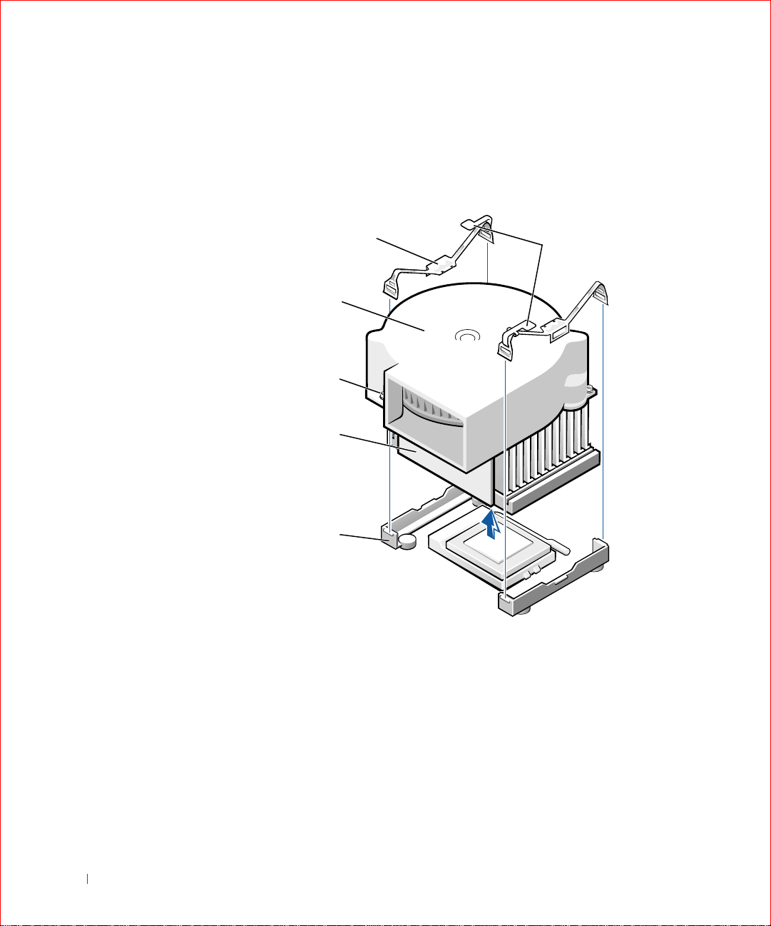
Small form-factor and small desktop computers: The heat sink is
attached to the blower. Remove the securing clips to remove the heat
sink/blower assembly.
Heat Sink/Blower Assembly Removal—Small Form-Factor
and Small Desktop Computers
2
3
www.dell.com | support.dell.com
4
5
6
1
90 Installing Upgrades
1latches (2)
2securing clips (2)
3blower
4screws (2)
5heat sink
6retention base
Page 89

NOTICE: Lay the heat sink down with the thermal grease facing upward. Do
not lay the heat sink down with the thermal grease touching the work surface.
Lift the heat sink or heat sink/blower assembly away from the
2
microprocessor.
3 On the small form-factor and small desktop computers, remove the
two screws on the blower to remove it from the heat sink.
NOTICE: Do not discard the origin al heat sink and securing clips unless you
not
are installing a m i cro p ro c e sso r upg r ad e kit fr o m D ell . If you are
a microprocessor upgrade kit from Dell, reuse t he original heat sink, blower,
and securing clips when installing your new microprocessor.
4
Discard the original heat sink and securing clips.
installing
Removing the Microprocessor
NOTICE: Be careful not to bend any of the pins when yo u remove the
microprocessor from its socket. Bending the pins can permanently damage the
microprocessor.
Your microprocessor socket is a zero insertion force (ZIF) socket with a
lever-type handle that secures the microprocessor in, or releases it
from, the socket.
1 Pull the release lever straight up until the microprocessor is released,
and then remove the microprocessor from the socket.
2 Leave the release lever extended so that the socket is ready for the new
microprocessor.
NOTE: Do not discard
the blower; reuse the
blower. Your
microprocessor upgrade
kit from Dell includes on ly
a replacement heat sink
and two replacement
securing clips.
Installing Upgrades 91
Page 90

Micropro cessor Removal
1
2
www.dell.com | support.dell.com
1 release lever
2 microprocessor
3 ZIF socket
3
Installing the Microprocessor
NOTICE: Ground yourself by touching an unpainted met al surface on the
back of the computer.
NOTICE: Be careful not to bend any of the pins when you unpa ck the
microprocessor. Bending the pins can permanently damage the microprocessor .
1
Unpack the new microprocessor.
If any of the pins on the microprocessor appear to be bent, see
“Getting Help” for instructions on obtaining technical assistance.
2 Align the pin-1 corner of the microprocessor with the pin-1 corner of
the socket.
92 Installing Upgrades
NOTE: You must identify the pin-1 corner to correctl y position the
microprocessor.
Page 91

Microprocessor Installation
1 pin-1 corners of microprocessor
and socket aligned
1
NOTICE: You must position the microprocessor correctly in the socket to
avoid permanent damage to the micropro cessor and the computer when you
turn on the computer.
3
If the release lever on the socket is not fully extended, move it to that
position now.
4 With the pin-1 corners of the microprocessor and socket aligned, align
the pins on the microprocessor with the holes in the socket.
NOTICE: When you place the microprocessor in the socket, be sure that all of
the pins go into the corresponding holes on all sides of the socket. Be careful
not to bend the pins.
Installing Upgrades 93
Page 92

5 Set the microprocesso r lightly in the socket and make sure all pins are
headed into the correct holes. Because your computer uses a ZIF
socket, there is no need to use force (which could bend the pins if the
microprocessor is misaligned). When the microprocessor is positioned
correctly, press it with minimal pressure to seat it.
6 When the microprocessor is fully seated in the socket, pivot the release
lever back toward the socket until it snaps into place, securing the
microprocessor.
Replacing the Heat Sink or Heat Sin k/Blower Assembly
NOTICE: Ground yourself by touching an unpainted met al surface on the
www.dell.com | support.dell.com
back of the computer.
NOTICE: If you are installing a microprocessor replacement kit from Dell,
return the microprocessor to Dell in the same package in which your
replacement kit was sent.
not
NOTICE: If you are
reuse the origin al blow er/ hea t si nk asse mbly an d sec urin g clip s when r epl acin g
the microprocessor.
Remove the film covering the thermal grease on the bottom of the
1
installing a microprocessor upgrade kit from Dell,
heat sink.
2 On the small form-factor and small desktop computers, reinstall the
two screws that attach the blow er to the heat sink.
94 Installing Upgrades
3 Lower the heat sink or blower/heat sink assembly to the
microprocessor so tha t the heat sink fits in the retention base.
4 For each of the replacement metal clips, fit the end of the cl ip that
does not have the latch over its tab on the retention base. Then, fit the
middle of the clip over the middle tab on the retention base, and press
down on the clip’s latch to secure the clip to the retention base (see
the illustration for your computer in “Removing the Heat Sink or Heat
Sink/Blower Assembly”).
5 On the small mini-tower computer, lower the airflow shroud over the
heat sink.
6 Plug the fan cable into its connector on the system board.
7 Plug the 12-volt power cable into its connector on the system board.
8 Close the computer cover, reconnect your computer and devices to
their electrical outlets, and turn them on.
Page 93

As the computer boots, it detects the presence of the new
microprocessor and automatically changes the configuration
information in system setup.
9 Enter system setup and conf irm that the Microprocessor option
correctly identifies the installed microprocessor.
10 Run the Dell Diagnostics to verify that the new microp rocessor is
operating correctly.
Front Panel Inserts
Removing Front Panel Inserts—Small Form-Factor and Small
Desktop Computers
1 Open the computer cover.
2 Facing the front of the computer, use your fingers to remove the front
panel cover.
Small Form-Factor Computer
Installing Upgrades 95
Page 94

www.dell.com | support.dell.com
96 Installing Upgrades
Page 95
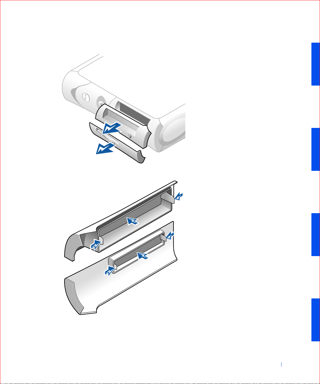
Small Desktop Computer
3 Press on the insert until it pops free of the front panel cover.
Installing Upgrades 97
Page 96

Removing Front Panel Inserts—Small Mini-Tower Computer
1 Open the computer cover to a 45-degree angle and disconnect the
CD/DVD drive data cable.
2 Open the cover to a 90-degree angle and release the insert tabs from
inside the computer.
Small Mini-Tower Computer
www.dell.com | support.dell.com
98 Installing Upgrades
Press on the insert until it pops free of the front panel cover.
3
Page 97

Replacing Front Panel Inserts
To replace a front panel insert, follow the “Removing Front Panel Inserts”
procedures in reverse.
Installing Upgrades 99
Page 98

Internal Drives
This computer may support the following internal drives:
• Small form-factor: one enhanced integrated drive electronics (IDE)
hard drive; one floppy or optional Zip drive; and one optional CD,
CD-RW, or DVD drive.
• Small desktop: one enhanced IDE ha rd drive; one floppy or optional
Zip drive; and one optional CD, CD-RW, or DVD drive.
• Small mini-tower: two enhanced IDE hard drives; two floppy or
optional Zip drives; and two optional CD, CD-RW, or DVD drives.
www.dell.com | support.dell.com
Small Form-Factor Computer
1
2
3
100 Installing Upgrades
1 CD/DVD drive
2 floppy drive
3 hard driv e
Page 99

Small Desktop Computer
2
3
1
1 CD/DVD drive
2 floppy drive
3 hard driv e
Installing Upgrades 101
Page 100

Small Mini-Tower Computer
2
1
3
www.dell.com | support.dell.com
1 CD/DVD drive(s)
2 floppy drive(s)
3 hard drive(s)
102 Installing Upgrades
IDE Drive Addressing
All IDE devices require that you configure the cable select setting, which
assigns master and slave status to devices according to their position on the
interface cable. You usually configure a drive for cable select by setting a
jumper or switch, depending on the drive. Refer to t he drive documentation
in your upgrade kit for information on configuring devices for the cable
select setting. When you connect two IDE devices to a single IDE int erface
cable and configure them for the cable select setting, the device attached to
the last connector on the interface cable is the master or boot device (drive
0), and the device attached to the middle connector on the interface cable
is the slave device (drive 1).
 Loading...