

Page 1

Precision 7550
Setup and specifications guide
Regulatory Model: P93F
Regulatory Type: P93F001
June 2020
Rev. A00
Page 2

Notes, cautions, and warnings
NOTE: A NOTE indicates important information that helps you make better use of your product.
CAUTION: A CAUTION indicates either potential damage to hardware or loss of data and tells you how to avoid the
problem.
WARNING: A WARNING indicates a potential for property damage, personal injury, or death.
© 2020 Dell Inc. or its subsidiaries. All rights reserved. Dell, EMC, and other trademarks are trademarks of Dell Inc. or its subsidiaries. Other trademarks may
be trademarks of their respective owners.
Page 3

Contents
Chapter 1: Set up your computer......................................................................................................5
Chapter 2: Chassis overview............................................................................................................ 7
Display view............................................................................................................................................................................ 7
Right view...............................................................................................................................................................................9
Left view............................................................................................................................................................................... 10
Palmrest view........................................................................................................................................................................ 11
Back view.............................................................................................................................................................................. 12
Bottom view..........................................................................................................................................................................13
Keyboard shortcuts..............................................................................................................................................................13
Chapter 3: Technical specifications.................................................................................................15
Processors............................................................................................................................................................................ 15
Chipset...................................................................................................................................................................................16
Operating system.................................................................................................................................................................16
Memory................................................................................................................................................................................. 16
Storage.................................................................................................................................................................................. 17
Audio and Speaker............................................................................................................................................................... 18
Graphics and Video controller.............................................................................................................................................18
Media-card reader................................................................................................................................................................19
Communications...................................................................................................................................................................19
Ports and connectors......................................................................................................................................................... 20
Power adapter...................................................................................................................................................................... 21
Battery...................................................................................................................................................................................21
Dimensions and weight....................................................................................................................................................... 23
Keyboard...............................................................................................................................................................................23
Touchpad..............................................................................................................................................................................23
Fingerprint reader................................................................................................................................................................24
Display................................................................................................................................................................................... 24
Camera..................................................................................................................................................................................25
Security.................................................................................................................................................................................26
Service and support............................................................................................................................................................ 26
Computer environment.......................................................................................................................................................27
Chapter 4: Software......................................................................................................................28
Downloading Windows drivers...........................................................................................................................................28
Chapter 5: System setup............................................................................................................... 29
Boot menu............................................................................................................................................................................29
Navigation keys....................................................................................................................................................................29
Boot Sequence.................................................................................................................................................................... 30
BIOS setup........................................................................................................................................................................... 30
Overview.........................................................................................................................................................................30
Boot configuration..........................................................................................................................................................31
Contents 3
Page 4

Integrated Devices.........................................................................................................................................................32
Storage............................................................................................................................................................................33
Display............................................................................................................................................................................. 33
Connection options....................................................................................................................................................... 33
Power management...................................................................................................................................................... 34
Security...........................................................................................................................................................................35
Password........................................................................................................................................................................ 36
Update and Recovery....................................................................................................................................................37
System management.................................................................................................................................................... 38
Keyboard.........................................................................................................................................................................39
Pre-boot behavior......................................................................................................................................................... 40
Virtualization support.................................................................................................................................................... 40
Performance................................................................................................................................................................... 41
System logs.....................................................................................................................................................................41
Updating the BIOS in Windows ........................................................................................................................................ 42
Updating BIOS on systems with BitLocker enabled..................................................................................................42
Updating your system BIOS using a USB flash drive................................................................................................43
System and setup password..............................................................................................................................................43
Assigning a system setup password............................................................................................................................44
Deleting or changing an existing system setup password........................................................................................44
Chapter 6: Getting help................................................................................................................. 45
Contacting Dell.................................................................................................................................................................... 45
4
Contents
Page 5
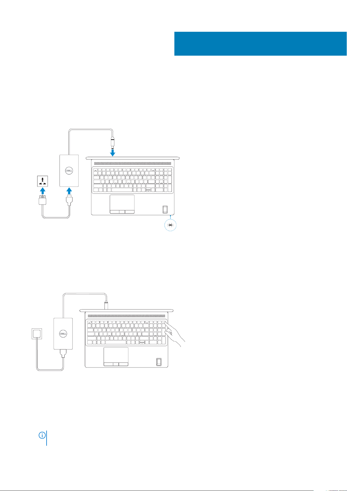
Steps
1. Connect the power cable.
1
Set up your computer
2. Press the power button.
3. Finish Windows system setup.
Follow the on-screen instructions to complete the setup. When setting up, Dell recommends that you:
• Connect to a network for Windows updates.
If connecting to a secured wireless network, enter the password for the wireless network access when
NOTE:
prompted.
Set up your computer 5
Page 6
• If connected to the internet, sign-in with or create a Microsoft account. If not connected to the internet, create an offline account.
• On the Support and Protection screen, enter your contact details.
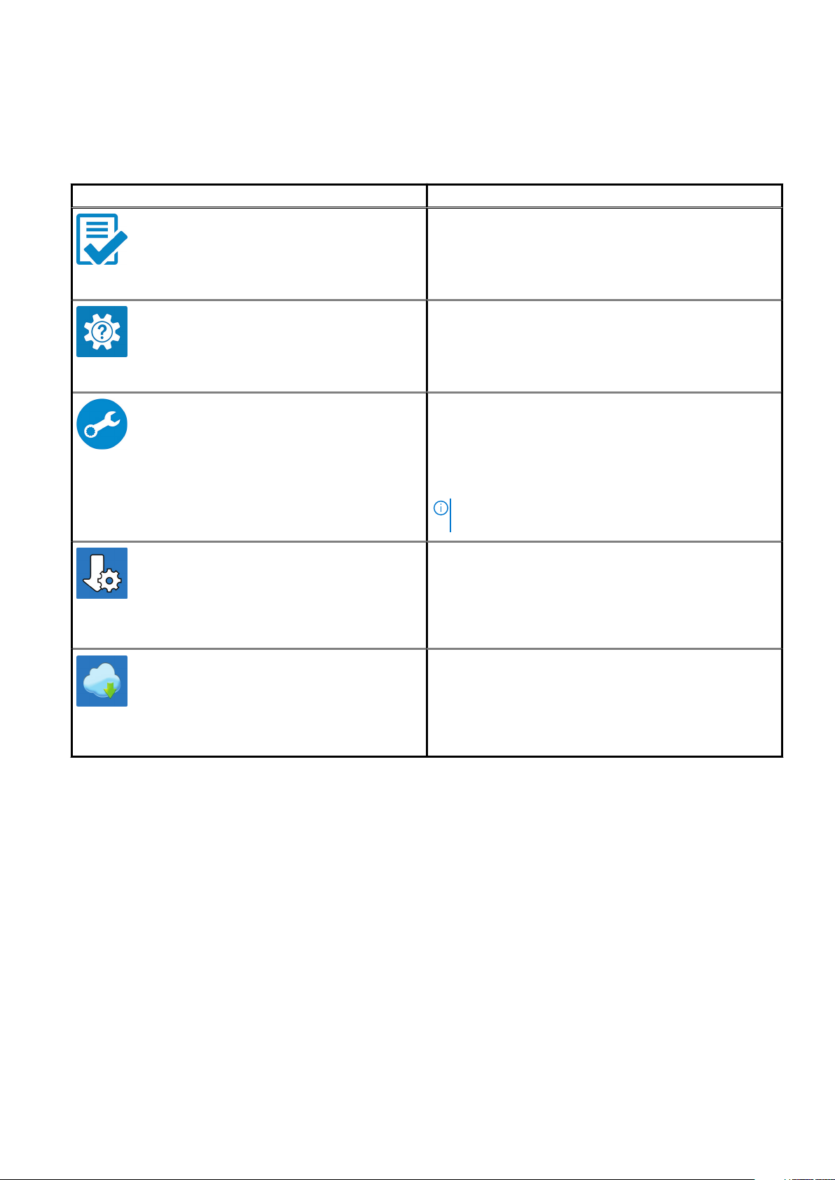
4. Locate and use Dell apps from the Windows Start menu—Recommended.
Table 1. Locate Dell apps
Dell apps Details
Dell Product Registration
Register your computer with Dell.
Dell Help & Support
Access help and support for your computer.
SupportAssist
Proactively checks the health of your computer’s hardware and
software.
NOTE: Renew or upgrade your warranty by clicking the
warranty expiry date in SupportAssist.
Dell Update
Updates your computer with critical fixes and important device
drivers as they become available.
Dell Digital Delivery
Download software applications including software that is
purchased but not preinstalled on your computer.
6 Set up your computer
Page 7
Topics:
• Display view
• Right view
• Left view
• Palmrest view
• Back view
• Bottom view
• Keyboard shortcuts
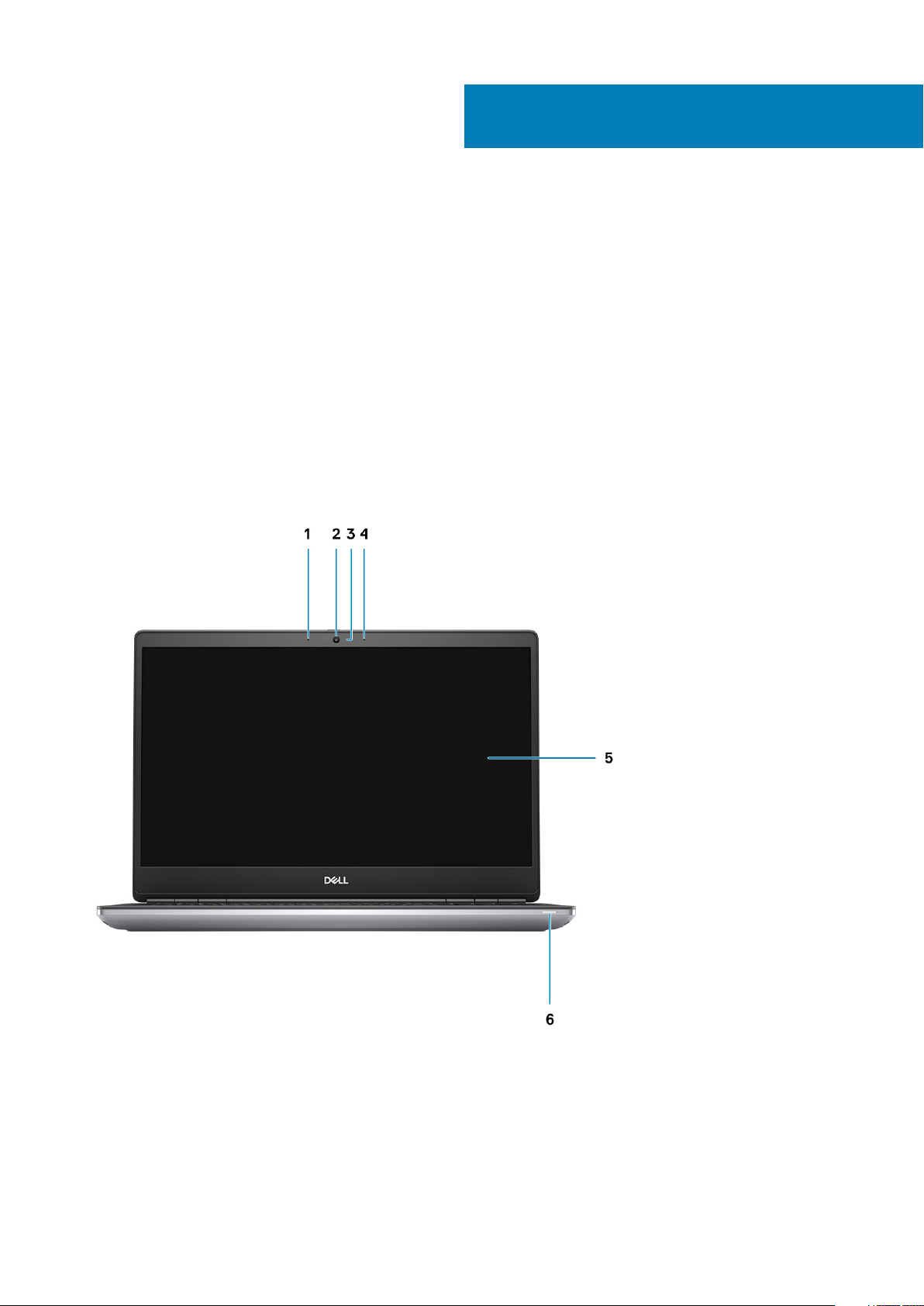
Display view
Display view with RGB camera
2
Chassis overview
1. Microphone
2. Camera
3. Camera LED
4. Microphone
5. Display
6. Battery status light
Chassis overview 7
Page 8
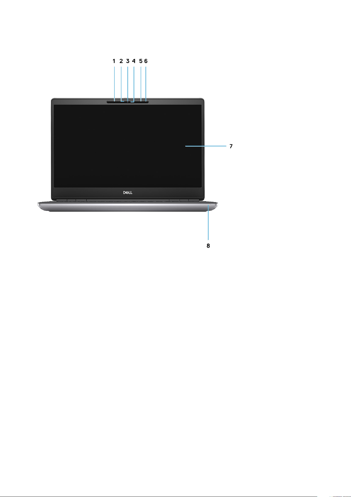
Display view with IR camera
1. Microphone
2. IR camera sensor
3. Camera
4. Camera LED
5. Microphone
6. Proximity sensor
7. Display
8. Battery status light
8
Chassis overview
Page 9
Right view
1.
SD card reader
2. Headset/Microphone port
3. USB 3.2 Gen 1 Type-A port
4. USB 3.2 Gen 1 Type-A port with PowerShare
5. Wedge-shaped lock slot
Chassis overview
9
Page 10

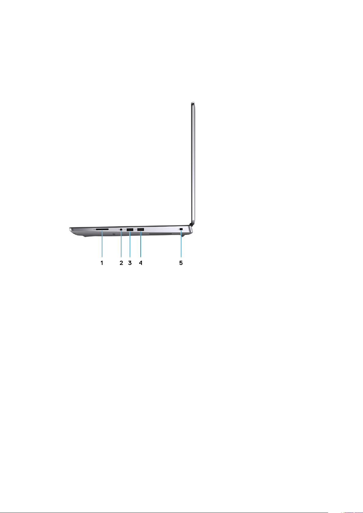
Left view
1.
USB 3.2 Gen 2 Type-C Thunderbolt 3 port
2. USB 3.2 Gen 2 Type-C Thunderbolt 3 port
3. Smart card-reader (optional)
10
Chassis overview
Page 11
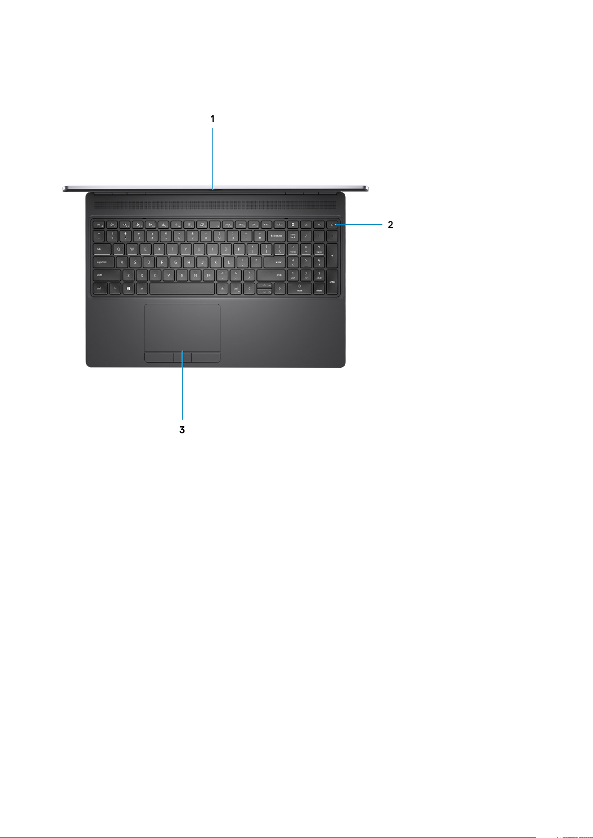
Palmrest view
1.
Camera shutter
2. Power button with optional fingerprint reader
3. Touchpad
Chassis overview
11
Page 12
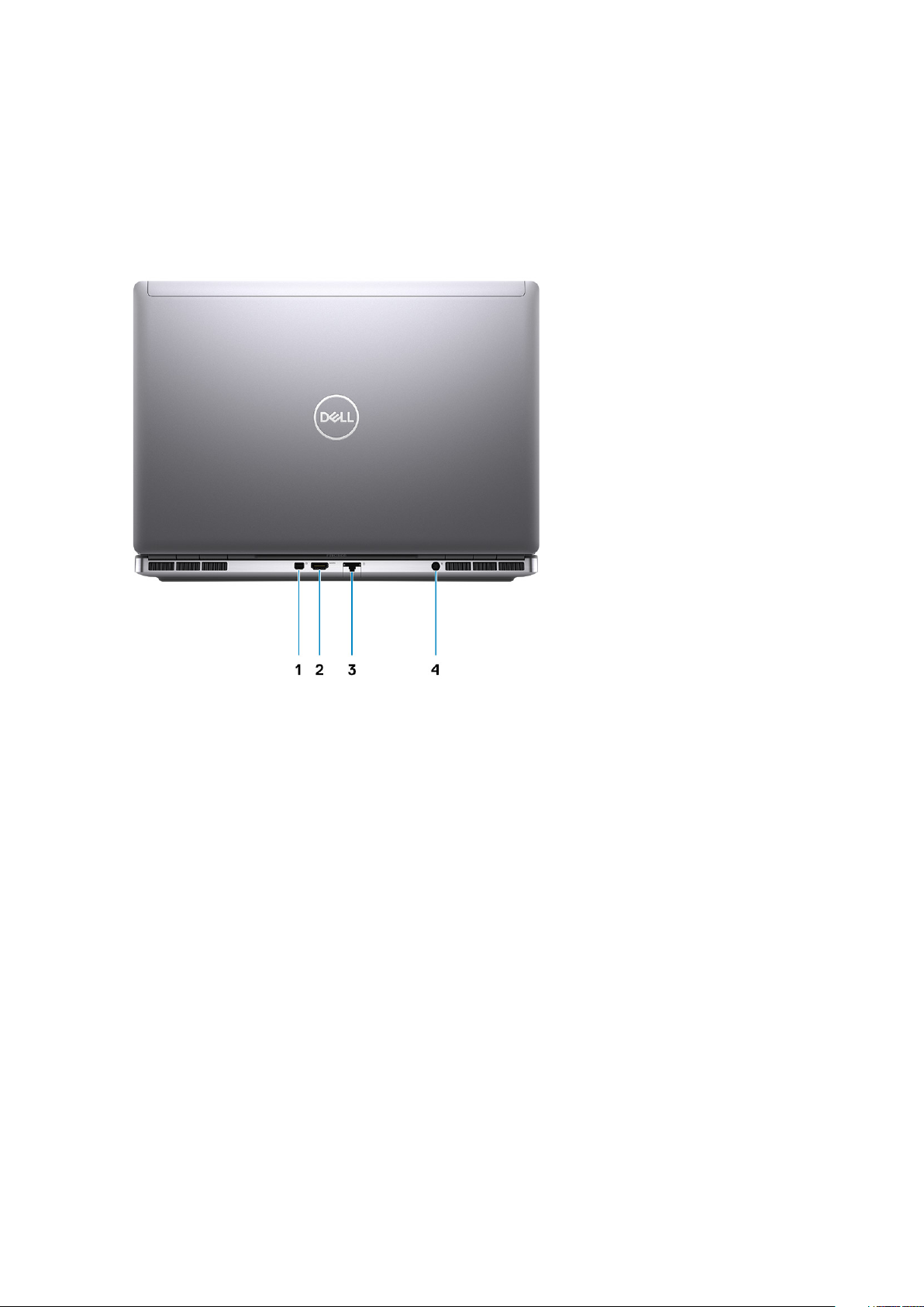
Back view
1.
Mini DisplayPort 1.4
2. HDMI 2.0 port
3. Network port
4. Power adapter port
12
Chassis overview
Page 13
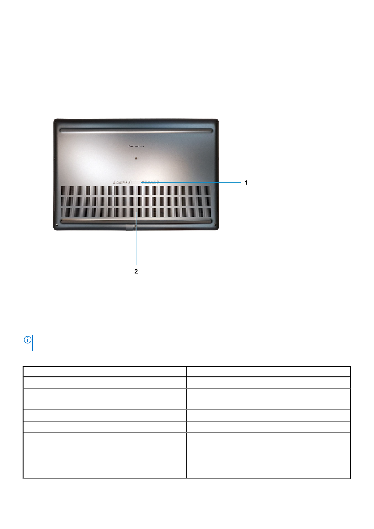
Bottom view
1.
Service tag label
2. Fan vent
Keyboard shortcuts
NOTE:
Keyboard characters may differ depending on the keyboard language configuration. Keys that are used for
shortcuts remain the same across all language configurations.
Table 2. List of keyboard shortcut keys
Hot keys Function
Fn+ESC - Fn Lock Allows the user to toggle between locked and unlocked Fn keys.
Fn+F1 - Audio Volume Mute
Fn+F2 – Audio Volume Down/Decrease Decreases the audio volume until minimum/off is reached.
Fn+F3 – Audio Volume Up/Increase Increases the audio volume until maximum is reached.
Fn+F4 – Microphone Mute
Temporarily mutes/unmutes the audio. The audio level before
muting is returned after unmuting.
Silences the on-board microphone so it cannot record audio. There
is an LED on the F4 function key that notifies the user of the state
of this feature:
• LED off = microphone capable of recording audio
• LED on = microphone muted and unable to record audio
Chassis overview 13
Page 14

Table 2. List of keyboard shortcut keys (continued)
Hot keys Function
Fn+F6—Scroll lock Used as Scroll Lock key.
Fn+F8 – LCD and Projector display
Fn+F9 – Search Mimics the Windows key + F keystroke to open Windows Search
Fn+F10 – KB Illumination/Backlight Determines the Keyboard Illumination/Backlight brightness level.
Fn+F11 - Print screen It is used as Print Screen key
Fn+F12 - Insert It is used as Insert key
Fn+RightCtrl – Context Menu It is used as Context Menu key. (a.k.a. Right-Click menu)
Fn+Left Cursor—Home It is used as Home key.
Fn+Right Cursor – End It is used as End key.
Fn+B – Pause/Break It is used as Pause/Break key. Specifically, Fn+B = Pause and Fn
Fn+Arrow Key (Up) – Brightness Decrease
Fn+Arrow Key (Down) – Brightness Increase
Determines video output to LCD and external Video devices when
attached and displays present.
dialog box.
The hot key cycles through the following brightness states when
pressed: Disabled, Dim, Bright. For more detail, see Keyboard
Illumination/Backlight section.
+Ctrl+B = Break.
Decreases the stepping of LCD brightness for each press until
minimum is reached. For details, see the LCD Brightness section.
Increases the stepping of LCD brightness for each press until
maximum is reached. For details, see the LCD Brightness section.
Fn+Home - Radio On/Off Toggles all the radios on and off. For example, WLAN, WWAN, and
Bluetooth.
Fn+End - Sleep Puts the system into the ACPI S3 State and does not wake the
system.
14 Chassis overview
Page 15

Technical specifications
NOTE: Offerings may vary by region. The following specifications are only those required by law to ship with your
computer. For more information about the configuration of your computer, go to Help and Support in your Windows
operating system and select the option to view information about your computer.
Topics:
• Processors
• Chipset
• Operating system
• Memory
• Storage
• Audio and Speaker
• Graphics and Video controller
• Media-card reader
• Communications
• Ports and connectors
• Power adapter
• Battery
• Dimensions and weight
• Keyboard
• Touchpad
• Fingerprint reader
• Display
• Camera
• Security
• Service and support
• Computer environment
3
Processors
Table 3. Processors
Processors Wattage Core
10th Generation
Intel Core
i5-10400H, vPro
10th Generation
Intel Core
i7-10750H
10th Generation
Intel Core
i7-10850H, vPro
10th Generation
Intel Core
i7-10875H, vPro
45 W 4 8 2.60 GHz to 4.60
45 W 6 12 2.60 GHz to 5.0
45 W 6 12 2.70 GHz to 5.1 GHz 12 MB Intel UHD Graphics 630
45 W 8 16 2.30 GHz to 5.10
count
Threa
d
count
Speed Cache Integrated graphics
8 MB Intel UHD Graphics 630
GHz
12 MB Intel UHD Graphics 630
GHz
16 MB Intel UHD Graphics 630
GHz
Technical specifications 15
Page 16

Table 3. Processors (continued)
Processors Wattage Core
10th Generation
Intel Core
i9-10885H, vPro
Intel Xeon
W-10855M, vPro
Intel Xeon
W-10885M, vPro
45 W 8 16 2.40 GHz to 5.30
45 W 6 12 2.80 GHz to 5.10
45 W 8 16 2.40 GHz to 5.30
count
Threa
d
count
Speed Cache Integrated graphics
GHz
GHz
GHz
Chipset
Table 4. Chipset
Description Values
Chipset
Processor
DRAM bus width
Intel WM490
10th Generation Intel Core i5/i7/i9/Xeon
64-bit
16 MB Intel UHD Graphics 630
12 MB Intel UHD Graphics P630
16 MB Intel UHD Graphics P630
Flash EPROM
PCIe bus
32 MB
Up to Gen3
Operating system
• Windows 10 Home (64-bit)
• Windows 10 Professional (64-bit)
• Windows 10 Enterprise (64-bit)
• Windows 10 Pro Education (64-bit)
• Windows 10 Pro China (64-bit)
• Windows 10 Pro for Workstations (64-bit)
• Red Hat Enterprise Linux 8.2 (Certification Only)
• Ubuntu 18.04 SP1
Memory
Table 5. Memory specifications
Description Values
Slots
Type
Four-SODIMM slots
Dual channel DDR4
Speed
Maximum memory
Minimum memory
16 Technical specifications
2666 MHz, 2933 MHz, 3200 MHz
128 GB
8 GB
Page 17

Table 5. Memory specifications (continued)
Description Values
Memory size per slot
Configurations supported
4 GB, 8GB, 16 GB, 32 GB
• 8 GB, 1 x 8 GB, DDR4, 2666 MHz, ECC, SODIMM
• 16 GB, 1 x 16 GB, DDR4, 2666 MHz, ECC, SODIMM
• 16 GB, 2 x 8 GB, DDR4, 2666 MHz, ECC, SODIMM
• 32 GB, 1 x 32 GB, DDR4, 2666 MHz, ECC, SODIMM
• 32 GB, 2 x 16 GB, DDR4, 2666 MHz, ECC, SODIMM
• 32 GB, 4 x 8 GB, DDR4, 2666 MHz, ECC, SODIMM
• 64 GB, 4 x 16 GB, DDR4, 2666 MHz, ECC, SODIMM
• 128 GB, 4 x 32 GB, DDR4, 2666 MHz, ECC, SODIMM
• 8 GB, 1 x 8 GB, DDR4, 2933 MHz, ECC, SODIMM
• 16 GB, 1 x 16 GB, DDR4, 2933 MHz, ECC, SODIMM
• 16 GB, 2 x 8 GB, DDR4, 2933 MHz, ECC, SODIMM
• 32 GB, 1 x 32 GB, DDR4, 2933 MHz, ECC, SODIMM
• 32 GB, 2 x 16 GB, DDR4, 2933 MHz, ECC, SODIMM
• 32 GB, 4 x 8 GB, DDR4, 2933 MHz, ECC, SODIMM
• 64 GB, 4 x 16 GB, DDR4, 2933 MHz, ECC, SODIMM
• 128 GB, 4 x 32 GB, DDR4, 2933 MHz, ECC, SODIMM
• 8 GB, 1 x 8 GB, DDR4, 2933 MHz, Non-ECC, SODIMM
• 16 GB, 1 x 16 GB, DDR4, 2933 MHz, Non-ECC, SODIMM
• 16 GB, 2 x 8 GB, DDR4, 2933 MHz, Non-ECC, SODIMM
• 32 GB, 1 x 32 GB, DDR4, 2933 MHz, Non-ECC, SODIMM
• 32 GB, 2 x 16 GB, DDR4, 2933 MHz, Non-ECC, SODIMM
• 32 GB, 4 x 8 GB, DDR4, 2933 MHz, Non-ECC, SODIMM
• 64 GB, 4 x 16 GB, DDR4, 2933 MHz, Non-ECC, SODIMM
• 128 GB, 4 x 32 GB, DDR4, 2933 MHz, Non-ECC, SODIMM
• 8 GB, 1 x 8 GB, DDR4, 3200 MHz SuperSpeed, Non-ECC,
SODIMM
• 16 GB, 1 x 16 GB, DDR4, 3200 MHz SuperSpeed, Non-ECC,
SODIMM
• 16 GB, 2 x 8 GB, DDR4, 3200 MHz SuperSpeed, Non-ECC,
SODIMM
• 32 GB, 4 x 8 GB, DDR4, 3200 MHz SuperSpeed, Non-ECC,
SODIMM
Storage
Your computer supports the following configurations:
• M.2 2230, solid-state drive (class 35)
• M.2 2280, solid-state drive (class 40)
• M.2 2280, solid-state drive (class 50)
The primary drive of your computer varies with the storage configuration.
Table 6. Storage specifications
Storage type Interface type Capacity
M.2 2230, Gen 3 PCIe x4 NVMe, Class 35 solid-state drive Gen 3 PCIe NVMe Up to 256 GB
M.2 2280, Gen 3 PCIe x4 NVMe, Class 40 solid-state drive Gen 3 PCIe NVMe Up to 2 TB
M.2 2280, Gen 3 PCIe x4 NVMe, Class 50 solid-state drive Gen 3 PCIe NVMe Up to 1 TB
Technical specifications 17
Page 18

Table 6. Storage specifications (continued)
Storage type Interface type Capacity
M.2 2280, Gen 3 PCIe x4 NVMe, Class 40 SED solid-state
drive
Gen 3 PCIe NVMe Up to 1 TB
Audio and Speaker
Table 7. Audio specifications
Description Values
Type
Controller
Stereo conversion
Internal interface
External interface
Speakers
Internal speaker amplifier
External volume controls
4 Channel High Definition Audio
Realtek ALC3281
Supported
High definition audio interface
Universal Audio Jack
2
Supported (audio codec integrated)
Keyboard shortcut controls
Speaker output average
Speaker output peak
Subwoofer output
Microphone
2 W
2.5 W
Not supported
Dual-array microphones
Graphics and Video controller
Table 8. Integrated graphics specifications
Controller External display support Memory size Processor
Intel UHD Graphics 630 mDP/HDMI/Type-C Shared system memory 10th Generation Intel
Core i5/i7/i9
Intel UHD Graphics P630 mDP/HDMI/Type-C Shared system memory Intel Xeon
Table 9. Discrete graphics specifications
Controller External display support Memory size Memory Type
NVIDIA Quadro T1000 mDP/HDMI/Type-C 4 GB GDDR6
NVIDIA Quadro T2000 mDP/HDMI/Type-C 4 GB GDDR6
NVIDIA Quadro RTX3000 mDP/HDMI/Type-C 6 GB GDDR6
NVIDIA Quadro RTX4000 mDP/HDMI/Type-C 8 GB GDDR6
18 Technical specifications
Page 19

Table 9. Discrete graphics specifications (continued)
Controller External display support Memory size Memory Type
NVIDIA Quadro RTX5000 mDP/HDMI/Type-C 16 GB GDDR6
Media-card reader
The following table lists the media cards supported by your Precision 7550.
Table 10. Media-card reader specifications
Description Values
Media-card type
Media-cards supported
NOTE: The maximum capacity supported by the media-card reader varies depending on the standard of the media card
installed in your computer.
1 SD card
• Secure Digital (SD)
• Secure Digital High Capacity (SDHC)
• Secure Digital Extended Capacity (SDXC)
Communications
Ethernet
Table 11. Ethernet specifications
Description Values
Model number
Transfer rate
Intel Ethernet Connection I219-LM
10/100/1000 Mbps
Wireless LAN module
Table 12. Wireless LAN module specifications
Description Values
Model number
Transfer rate
Frequency bands supported
Wireless standards
Encryption
Intel Wi-Fi 6 AX201
Up to 2400 Mbps
2.4 GHz/5 GHz
• Wi-Fi 802.11a/b/g
• Wi-Fi 4 (WiFi 802.11n)
• Wi-Fi 5 (WiFi 802.11ac)
• Wi-Fi 6 (WiFi 802.11ax)
• 64-bit/128-bit WEP
• AES-CCMP
• TKIP
Technical specifications 19
Page 20

Table 12. Wireless LAN module specifications (continued)
Description Values
Bluetooth
Bluetooth 5.1
WWAN module
Table 13. WWAN module specifications
Description Values
Model number Qualcomm Snapdragon X20 LTE (DW5821e)
Transfer rate Up to 1 Gbps DL/150 Mbps UL (Cat 16)
Frequency bands supported
Network standards
Host interface USB 3.2 Gen 1/ USB 2.0
Power supply DC 3.135 V to 4.4 V, Typical 3.3 V
Antenna connector
• (1, 2, 3, 4, 5, 7, 8, 12, 13, 14, 17, 18, 19, 20, 25, 26, 28, 29, 30, 32,
38, 39, 40, 41, 42, 43, 46, 66)
• HSPA+ (1, 2, 4, 5, 6, 8, 9,19)
• LTE FDD/TDD
• WCDMA/HSPA+
• GPS/GLONASS/Beidou/Galileo
• WWAN Main Antenna x 1
• WWAN Diversity Antenna x 1
• 4 x 4 MIMO Antenna x 2
NOTE: WWAN configuration not available with computers with IR camera.
Ports and connectors
Table 14. Ports and connectors
Description Values
External:
Network
USB
Audio
Video
Memory card reader
Smart card reader 1 Smart card reader
Micro Subscriber Identity Module (uSIM) Card 1 Micro SIM card
1 RJ-45 port 10/100/1000 Mbps
• 1 USB 3.2 Gen 1 Type-A port
• 1 USB 3.2 Gen 1 Type-A port with PowerShare
• 2 USB 3.2 Gen 2 Type-C Thunderbolt 3 ports
1 Universal audio Jack
1 HDMI 2.0 port, 1 Mini DisplayPort 1.4
1 SD 6.0
* UMA with HBR2
Power port
Security
20 Technical specifications
DC-in port (7.4 mm standard plug)
1 Wedge-shaped security slot
Page 21

Table 14. Ports and connectors (continued)
Description Values
Internal:
M.2
• Three PCIe expansion card slots
• Two SATA M.2 2280 slot for solid-state drive
• Three NVMe M.2 2280 slot for solid-state drive
NOTE: To learn more about the features of different
types of M.2 cards, see the knowledge base article
SLN301626.
Power adapter
Table 15. Power adapter specifications
Description Values
Type
Diameter (connector)
Dimensions (L x W x H)
Weight
Input voltage
Input frequency
180 W adapter
7.40 mm
23 mm x 75 mm x 152 mm ( 0.91 in. x 2.95 in. x 5.98 in.)
1.28 lbs/ 0.58 kg
100 VAC x 240 VAC
50 Hz x 60 Hz
Input current (maximum)
Output current (continuous)
Rated output voltage
Temperature range:
Operating
Storage
2.34 A
9.23 A
19.50 VDC
0°C to 40°C (32°F to 104°F)
-40°C to 70°C (-40°F to 158°F)
Battery
Table 16. Battery specifications
Description Values
Type
Voltage
Weight (maximum)
6-cell, 68 WHr, Lithium-ion,
ExpressChargeBoost
11.40 VDC 11.40 VDC 11.40 VDC
0.39 Kg (0.86 lb) 0.43 kg (0.95 lb) 0.43 kg (0.95 lb)
6-cell, 95 WHr, Lithium-ion,
ExpressCharge Boost
6-cell, 95 WHr, Lithium-ion LcL
Dimensions:
Height
10. 3 mm (0.41 in.) 10. 3 mm (0.41 in.) 10. 3 mm (0.41 in.)
Technical specifications 21
Page 22

Table 16. Battery specifications (continued)
Description Values
Width
Depth
Temperature range:
Operating
Storage
Operating time Varies depending on operating
Charging time (approximate)
284.00 mm (11.18 in.) 284.00 mm (11.18 in.) 284.00 mm (11.18 in.)
76.75 mm (3.02 in.) 76.75 mm (3.02 in.) 76.75 mm (3.02 in.)
0 °C to 60 °C (32 °F to 140 °F) 0 °C to 60 °C (32 °F to 140 °F) 0 °C to 60 °C (32 °F to 140
–20 °C to 60 °C (-4 °F to
140°F)
conditions and can significantly
reduce under certain powerintensive conditions.
Express Charge Method:
• 0 - 15°C maximum allowable
charge time from 0 to 100%
RSOC is 4 hours
• 16 - 45°C normal express
charge¹
• 46 - 50°C maximum
allowable charge time from 0
to 100% RSOC is 3 hours
NOTE: 0 to 80% RSOC in
60 minutes; 0 to 100%
RSOC in 120 minutes
–20 °C to 60 °C (-4 °F to
140°F)
Varies depending on operating
conditions and can significantly
reduce under certain powerintensive conditions.
Express Charge Method:
• 0 - 15°C maximum allowable
charge time from 0 to 100%
RSOC is 4 hours
• 16 - 45°C normal express
charge¹
• 46 - 50°C maximum
allowable charge time from 0
to 100% RSOC is 3 hours
NOTE: 0 to 80% RSOC in
60 minutes; 0 to 100%
RSOC in 120 minutes
°F)
–20 °C to 60 °C (-4 °F to
140°F)
Varies depending on operating
conditions and can significantly
reduce under certain powerintensive conditions.
Standard Charge/
Predominately AC User
Charge Method
• 0 - 15°C maximum allowable
charge time from 0 to 100%
RSOC is 4 hours
• 16 - 50°C maximum
allowable charge time from 0
to 100% RSOC is 3 hours
Standard Charge/
Predominately AC User
Charge Method
• 0 - 15°C maximum allowable
charge time from 0 to 100%
RSOC is 4 hours
• 16 - 50°C maximum
allowable charge time from 0
to 100% RSOC is 3 hours
Express Charge Boost Charge
Method (Fast Charge for
Initial 35%)
• 16 - 45°C target charge time
from 0 to 35% RSOC is
20mins for Accelerated
Charge
Life span (approximate) 300 discharge/charge cycles 300 discharge/charge cycles 1000 discharge/charge cycles
Coin-cell battery
Operating time Varies depending on operating
Supported Supported Supported
conditions and can significantly
reduce under certain powerintensive conditions.
Standard Charge/
Predominately AC User
Charge Method
• 0 - 15°C maximum allowable
charge time from 0 to 100%
RSOC is 4 hours
• 16 - 50°C maximum
allowable charge time from 0
to 100% RSOC is 3 hours
Express Charge Boost
Charge Method (Fast Charge
for Initial 35%)
• 16 - 45°C target charge time
from 0 to 35% RSOC is
20mins for Accelerated
Charge
Varies depending on operating
conditions and can significantly
reduce under certain powerintensive conditions.
Varies depending on operating
conditions and can significantly
reduce under certain powerintensive conditions.
22 Technical specifications
Page 23

Dimensions and weight
Table 17. Dimensions and weight
Description Values
Height:
Front
Rear
Width
Depth
Weight (starting at)
25.00 mm (00.98 in.)
27.36 mm (1.08 in.)
360.00 mm (14.17 in.)
242.00 mm (9.53 in.)
2.45 kg (5.42 lb)
NOTE: The weight of your computer depends on the
configuration ordered and the manufacturing variability.
Keyboard
Table 18. Keyboard specifications
Description Values
Type
Layout
Number of keys
Standard keyboard
QWERTY
• United States and Canada: 101 keys
• United Kingdom: 102 keys
• Japan: 105 keys
Size
Shortcut keys
X=18.70 mm key pitch
Y=18.05 mm key pitch
Some keys on your keyboard have two symbols on them. These
keys can be used to type alternate characters or to perform
secondary functions. To type the alternate character, press Shift
and the desired key. To perform secondary functions, press Fn and
the desired key.
Touchpad
Table 19. Touchpad specifications
Description Values
Resolution:
Horizontal
Vertical
1084
984
NOTE: You can define the primary behavior of the
function keys (F1–F12) changing Function Key Behavior
in BIOS setup program.
Technical specifications 23
Page 24

Table 19. Touchpad specifications (continued)
Description Values
Dimensions:
Horizontal
Vertical
3.92 inches (99.50 mm )
80 mm (3.15 in.)
Fingerprint reader
The following table lists the fingerprint-reader specifications of your Precision 7550.
Table 20. Fingerprint reader on power button specifications
Description Values
Fingerprint-reader sensor technology
Fingerprint-reader sensor resolution
Fingerprint-reader sensor pixel size
Fingerprint-reader sensor
Table 21. Fingerprint reader on palmrest specifications
Description Values
Capacitive
500 / 363 ppi
• X: 108 / 76
• Y: 88 / 100
• Horizontal: 8.40 mm x 6.90 mm
• Vertical: 8.40 mm x 5.25 mm
Fingerprint-reader sensor technology Capacitive
Fingerprint-reader sensor resolution 508 dpi
Fingerprint-reader sensor pixel size 360
Display
The following table lists the display specifications of your Precision 7550.
Table 22. Display specifications
Description Option one Option two Option three Option four Option five
Display type
Display-panel
technology
Display-panel
dimensions (active
area):
Height
15.6 in. Full High
Definition (FHD)
WVA (Wide view
angle )
193.59 mm (7.62 in.) 193.59 mm (7.62 in.) 193.59 mm (7.62 in.) 193.59 mm (7.62
15.6 in. Full High
Definition (FHD)
WVA (Wide view
angle )
15.6 in. Full High
Definition (FHD)
WVA (Wide view
angle )
15.6 in. Ultra High
Definition (UHD)
HDR400
in.)
15.6 in. Ultra High
Definition (UHD)
HDR600
193.59 mm (7.62
in.)
Width
24 Technical specifications
344.16 mm (13.55 in.) 344.16 mm (13.55 in.) 344.16 mm (13.55 in.) 344.16 mm (13.55
in.)
344.16 mm (13.55
in.)
Page 25

Table 22. Display specifications (continued)
Description Option one Option two Option three Option four Option five
Diagonal
Display-panel native
resolution
Luminance (typical)
Megapixels
Color gamut
Pixels Per Inch (PPI)
Contrast ratio (typ)
Response time (max)
Refresh rate
Horizontal view angle
Vertical view angle
394.87 mm (15.60 in.) 394.87 mm (15.60 in.) 394.87 mm (15.60
in.)
1920 x 1080 1920 x 1080 1920 x 1080 3840 x 2160
220 nits 500 nits 500 nits 500 nits
2.07 2.07 2.07 8.29
45% NTSC 100% DCIP3 100% DCIP3 100% Adobe
141 141 141 282
600:01 600:01 600:01 1500:1
35 ms 35 ms 35 ms 35 ms
60 Hz 60 Hz 60 Hz 60 Hz
+/- 80 degrees(min) +/- 80 degrees(min) +/- 80 degrees(min) +/- 80
+/- 80 degrees(min) +/- 80 degrees(min) +/- 80 degrees(min) +/- 80
394.87 mm (15.55
in.)
degrees(min)
degrees(min)
394.87 mm (15.55
in.)
3840 x 2160
600 nits
8.29
100% Adobe
282
6000:1
35
60
+/- 80
degrees(min)
+/- 80
degrees(min)
Pixel pitch
Power consumption
(maximum)
Anti-glare vs glossy
finish
Touch options
0.18 x 0.18 mm 0.18 x 0.18 mm 0.18 x 0.18 mm 0.090 x 0.090 mm
4.20 W 7.2 W 7.4 W 10 W
Anti-glare Anti-glare Anti-glare Anti-glare
No No Yes No
Camera
Table 23. Camera specifications
Description Values
Number of cameras
Type
Location
Sensor type
One
There are 2 camera options:
• HD RGB camera
• IR camera
Front camera
Proximity sensor technology
0.090 x 0.090 mm
18 W
Anti-glare
No
Resolution
Camera
Still image
0.92 megapixel
Technical specifications 25
Page 26

Table 23. Camera specifications (continued)
Description Values
Video
Infrared camera
Still image
Video
Diagonal viewing angle
Camera
Infrared camera
1280 x 720 (HD) at 30 fps
0.30 megapixel
1280 x 720 (HD) at 30 fps
74.9 degrees
70 degrees
Security
Table 24. Security
Security options Precision 7550
Trusted Platform Module (TPM) 2.0 Discreet TPM 2.0 IC FIPS-140-2 Certified / TCG Certified, TCG
Certificatication for TPM (Trusted Computing Group)
Firmware TPM Supported
Chassis lock slot and loop support Yes, wedge-shaped lock slot
Finger print Reader Two Optional fingerprint reader
• on Power button
• FIPS fingerprint reader in the palmrest
Optional Security Hardware Authentication Bundles
• Touch Fingerprint Reader (in Power Button) with Control Vault 3.0
Advanced Authentication with FIPS 140-2 Level 3 Certification
• Contacted Smart Card and Control Vault 3 Advanced Authentication
with FIPS 140-2 Level 3 Certification
• Touch Fingerprint Reader (in Power Button), Contacted Smart Card,
and Control Vault 3 Advanced Authentication with FIPS 140-2 Level 3
Certification
• Touch Fingerprint Reader in Power Button, Contacted Smart Card,
Contactless Smart Card, NFC, and Control Vault 3 Advanced
Authentication with FIPS 140-2 Level 3 Certification
• Optional Face IR camera (Windows Hello compliant) with Proximity
Sensor
Service and support
For more details on Dell Service Plans, see https://www.dell.com/learn/us/en/19/services/warranty-support-
NOTE:
services.
Table 25. Warranty
Warranty
3 Years Hardware Service with Onsite/In-Home Service After Remote Diagnosis
4 Years Hardware Service with Onsite/In-Home Service after Remote Diagnosis
5 Years Hardware Service with Onsite/In-Home Service after Remote Diagnosis
26 Technical specifications
Page 27

Table 25. Warranty (continued)
Warranty
3 Years ProSupport with Next Business Day Onsite Service
4 Years ProSupport with Next Business Day Onsite Service
5 Years ProSupport with Next Business Day Onsite Service
3 Years ProSupport Plus with Next Business Day Onsite Service
4 Years ProSupport Plus with Next Business Day Onsite Service
5 Years ProSupport Plus with Next Business Day Onsite Service
Table 26. Accidental damage services
Accidental Damage Services
3 Years Accidental Damage Service
4 Years Accidental Damage Service
5 Years Accidental Damage Service
Computer environment
Airborne contaminant level: G1 as defined by ISA-S71.04-1985
Table 27. Computer environment
Description Operating Storage
Temperature range
Relative humidity (maximum)
Vibration (maximum)
Shock (maximum)
Altitude (maximum)
* Measured using a random vibration spectrum that simulates user environment.
† Measured using a 2 ms half-sine pulse when the hard drive is in use.
*
0°C to 35°C (32°F to 95°F) -40°C to 65°C (-40°F to 149°F)
10% to 90% (non-condensing) 0% to 95% (non-condensing)
0.66 GRMS 1.30 GRMS
110 G† 160 G†
-15.2 m to 3048 m (4.64 ft to 5518.4 ft) -15.2 m to 10668 m (4.64 ft to 19234.4 ft)
Technical specifications
27
Page 28

This chapter details the supported operating systems along with instructions on how to install the drivers.
Topics:
• Downloading Windows drivers
Downloading Windows drivers
Steps
1. Turn on the notebook.
2. Go to Dell.com/support.
3. Click Product Support, enter the Service Tag of your notebook, and then click Submit.
NOTE: If you do not have the Service Tag, use the auto detect feature or manually browse for your notebook model.
4. Click Drivers and Downloads.
5. Select the operating system installed on your notebook.
6. Scroll down the page and select the driver to install.
7. Click Download File to download the driver for your notebook.
8. After the download is complete, navigate to the folder where you saved the driver file.
9. Double-click the driver file icon and follow the instructions on the screen.
4
Software
28 Software
Page 29

5
System setup
CAUTION: Unless you are an expert computer user, do not change the settings in the BIOS Setup program. Certain
changes can make your computer work incorrectly.
NOTE: Before you change BIOS Setup program, it is recommended that you write down the BIOS Setup program screen
information for future reference.
Use the BIOS Setup program for the following purposes:
• Get information about the hardware installed in your computer, such as the amount of RAM and the size of the hard drive.
• Change the system configuration information.
• Set or change a user-selectable option, such as the user password, type of hard drive installed, and enabling or disabling base devices.
Topics:
• Boot menu
• Navigation keys
• Boot Sequence
• BIOS setup
• Updating the BIOS in Windows
• System and setup password
Boot menu
Press <F12> when the Dell logo appears to initiate a one-time boot menu with a list of the valid boot devices for the system. Diagnostics
and BIOS Setup options are also included in this menu. The devices listed on the boot menu depend on the bootable devices in the system.
This menu is useful when you are attempting to boot to a particular device or to bring up the diagnostics for the system. Using the boot
menu does not make any changes to the boot order stored in the BIOS.
The options are:
• UEFI Boot Devices:
○ Windows Boot Manager
○ UEFI Hard Drive
○ Onboard NIC (IPV4)
○ Onboard NIC (IPV6)
• Pre-Boot Tasks:
○ BIOS Setup
○ Diagnostics
○ BIOS Update
○ SupportAssist OS Recovery
○ BIOS Flash Update - Remote
○ Device Configuration
Navigation keys
For most of the System Setup options, changes that you make are recorded but do not take effect until you
NOTE:
restart the system.
Keys Navigation
Up arrow Moves to the previous field.
Down arrow Moves to the next field.
System setup 29
Page 30

Keys Navigation
Enter Selects a value in the selected field (if applicable) or follow the link in the field.
Spacebar Expands or collapses a drop-down list, if applicable.
Tab Moves to the next focus area.
Esc Moves to the previous page until you view the main screen. Pressing Esc in the main screen displays a message
that prompts you to save any unsaved changes and restarts the system.
Boot Sequence
Boot sequence enables you to bypass the System Setup–defined boot device order and boot directly to a specific device (for example:
optical drive or hard drive). During the Power-on Self-Test (POST), when the Dell logo appears, you can:
• Access System Setup by pressing F2 key
• Bring up the one-time boot menu by pressing F12 key.
The one-time boot menu displays the devices that you can boot from including the diagnostic option. The boot menu options are:
• Removable Drive (if available)
• STXXXX Drive
NOTE: XXXX denotes the SATA drive number.
• Optical Drive (if available)
• SATA Hard Drive (if available)
• Diagnostics
NOTE: Choosing Diagnostics, displays the SupportAssist diagnostics screen.
The boot sequence screen also displays the option to access the System Setup screen.
BIOS setup
NOTE: Depending on the tabletlaptop and its installed devices, the items listed in this section may or may not appear.
Overview
Table 28. Overview
Option Description
System Information
This section lists the primary hardware features of your computer.
The options are:
• System Information
○ BIOS version
○ Service Tag
○ Asset Tag
○ Manufacture Date
○ Ownership Date
○ Express Service Code
○ Ownership Tag
○ Signed Firmware Update
• Battery
○ Primary
○ Battery Level
○ Battery State
○ Health
30 System setup
Page 31

Table 28. Overview
Option Description
○ AC Adapter
• Processor Information
○ Processor Type
○ Maximum Clock Speed
○ Minimum Clock Speed
○ Current Clock Speed
○ Core Count
○ Processor ID
○ Processor L2 Cache
○ Processor L3 Cache
○ Microcode Version
○ Intel Hyper-Threading Capable
○ 64-Bit Technology
• Memory Configuration
○ Memory Installed
○ Memory Available
○ Memory Speed
○ Memory Channel Mode
○ Memory Technology
○ DIMM_Slot 1
○ DIMM_Slot 2
• Device Information
○ Panel Type
○ Video Controller
○ Video Memory
○ Wi-Fi Device
○ Native Resolution
○ Video BIOS Version
○ Audio Controller
○ Bluetooth Device
○ LOM MAC Address
Boot configuration
Table 29. Boot configuration
Option Description
Boot Sequence
Secure Boot
Allows you to change the order in which the computer attempts to
find an operating system.
The options are:
• Windows Boot Manager
• UEFI Hard Drive
• Onboard NIC (IPV4)
• Onboard NIC (IPV6)
NOTE: Legacy Boot mode is not supported on this
platform.
Secure Boot helps ensure your system boots using only validated
boot software.
Enable Secure Boot—By default, this option is disabled.
System setup 31
Page 32

Table 29. Boot configuration (continued)
Option Description
NOTE: The system has to be in UEFI boot mode to
enable Enable Secure Boot.
Secure Boot Mode
Expert Key Management
Changes to the Secure Boot operation mode modifies the behavior
of Secure Boot to allow evaluation of UEFI driver signatures.
The options are:
• Deployed Mode—By default, this option is enabled.
• Audit Mode
Allows you to enable or disable Expert Key Management.
Enable Custom Mode—By default, this option is disabled.
The Custom Mode Key Management options are:
• PK—By default, this option is enabled.
• KEK
• db
• dbx
Integrated Devices
Table 30. Integrated device options
Option Description
Date/Time
Allows you to set the date and time. The change to the system date
and time takes effect immediately.
Camera
Audio
USB Configuration
Allows you to enable or disable camera.
Enable Camera - This option is enabled by default.
Allows you to turn off all integrated audio. By default, the Enable
Audio option is selected.
Allows you to enable or disable the integrated audio or microphone and
speaker separately. By default, the Enable Audio option is selected.
The options are:
• Enable Microphone
• Enable Internal Speaker
Allows you to enable or disable the internal or integrated USB
configuration.
The options are:
• Enable USB Boot Support
• Enable External USB Port
By default, all the options are enabled.
32 System setup
Page 33

Storage
Table 31. Storage options
Option Description
SATA Operation
Storage Interface
SMART Reporting
Drive Information
Allows you to configure the operating mode of the integrated SATA
hard drive controller.
The options are:
• Disabled
• AHCI
• RAID On—By default, the RAID On option is enabled.
NOTE: SATA is configured to support RAID mode.
Allows you to enable or disable various drives on board.
The options are:
• M.2 PCIe SSD-1
• M.2 PCIe SSD-0
By default, all the options are enabled.
This field controls whether hard drive errors for integrated drives are
reported during system startup. This technology is part of the Self
Monitoring Analysis and Reporting Technology (SMART) specification.
By default, the Enable SMART Reporting option is disabled .
Provides information about drive type and device.
Display
Table 32. Display options
Option Description
Display Brightness
Full Screen Logo
Allows you to set the screen brightness when running on battery and
AC power.
The options are:
• Brightness on battery power - By default, set to 50.
• Brightness on AC power - By default, set to 100.
Displays full screen logo when the image matches screen resolution.
By default, all the option is disabled.
Connection options
Table 33. Connection
Option Description
Integrated NIC
Integrated NIC controls the onboard LAN controller. It allows preOS and early operating system networking features to use any
enabled NICs when UEFI networking protocols are installed and
available.
The options are:
System setup 33
Page 34

Table 33. Connection (continued)
Option Description
• Disabled
• Enabled
• Enabled with PXE - This option is enabled by default.
Wireless Device Enable
Enable UEFI Network Stack
Power management
Table 34. Power Management
Option Description
Battery Configuration
Allows the system to run on battery during peak power usage hours.
The options are:
• Adaptive—enabled by default
• Standard
• ExpressCharge
• Primarily AC Use
• Custom
NOTE: If Custom Charge is selected, you can also configure Custom Charge Start and
Custom Charge Stop.
Allows you to enable or disable the internal wireless devices.
The options are:
• WLAN
• Bluetooth
Both the options are enabled by default.
Allows you to control the onboard LAN controller. It allows pre-OS
and early operating system networking features to use any enabled
NICs when UEFI networking protocols are installed and available.
Enable UEFI Network Stack - This option is enabled by default.
Advanced Configuration
Peak Shift
Thermal Management
34 System setup
This option enables you to maximize the battery health.
By default, the Enable Advanced Battery Charge Mode option is disabled.
NOTE: The user can charge battery using feature Beginning of Day and Work Period.
By default, Work Period is disabled.
Use ExpressCharge for accelerated battery charging.
Allows the system to run on battery during peak power usage hours.
Peak Shift - By default, this option is disabled.
NOTE: The user can:
• Set Battery Threshold Min = 15, Max = 100
• Prevent AC power between certain times of the day using Peak Shift Start, Peak Shift
End, and Peak Shift Charge Start.
Allows cooling of fans and the processor heat management to adjust system performance, noise, and
temperature.
The options are:
Page 35

Table 34. Power Management (continued)
Option Description
• Optimized—enabled by default
• Cool
• Quiet
• Ultra Performance
USB Wake Support
Block Sleep
Lid Switch
Intel Speed Shift
technology
Enable USB Wake
Support
Wake on Dell USBC Dock
By default, the option Wake on Dell USB-C Dock is enabled.
NOTE: These features are only functional when the AC power adapter is connected. If the
AC power adapter is removed before Standby, the BIOS removes power from all USB ports
to conserve battery power.
This option enables you to block entering to sleep (S3) mode in operating system environment. By
default, the Block Sleep option is disabled.
NOTE: When Block Sleep is enabled, the system does not go to sleep. Intel Rapid Start
gets disabled automatically, and the operating system power option remains blank if it was
set to Sleep.
Allows you to disable the lid switch.
The options are:
• Enable Lid Switch—enabled by default
• Power On Lid Open—enabled by default
Allows you to enable or disable the Intel Speed Shift Technology support. By default,Intel Speed Shift
technology is enabled. Enabling this option allows the operating system to select appropriate processor
performance.
Allows you to enable USB devices to wake the system from standby mode.
By default, the option Enable USB Wake Support is disabled.
Allows you to connect a Dell USB-C Dock to wake the system from standby
mode.
Security
Table 35. Security
Option Description
TPM 2.0 Security
Intel Software Guard
Extensions
Allows you to enable or disable the Trusted Platform Module (TPM).
The options are:
• TPM 2.0 Security On—This option is enabled by default.
• PPI Bypass for Enable Commands
• PPI Bypass for Disable Commands
• PPI Bypass for Clear Command
• Attestation Enable—This option is enabled by default.
• Key Storage Enable—This option is enabled by default.
• SHA-256—This option is enabled by default.
• Clear
• TPM State—This option is enabled by default.
Provides a secure environment for running code or storing sensitive information in the context of the
main operating system and sets enclave reserve memory size.
Intel SGX
System setup 35
Page 36

Table 35. Security (continued)
Option Description
The options are:
• Disabled
• Enabled
• Software Control—This option is enabled by default.
SMM Security Mitigation
Data Wipe on Next Boot
Absolute This field allows you to Enable, Disable, or Permanently Disable the BIOS module interface of the optional
UEFI Boot Path Security
Allows you to enable or disable additional UEFI SMM Security Mitigation protection.
SMM Security Mitigation - By default, this option is enabled.
Allows BIOS to queue up data wipe cycle for storage devices connected to the motherboard on the next
reboot.
Start Data Wipe - By default, this option is disabled.
NOTE: Secure Wipe operation deletes information in a way that it cannot be
reconstructed.
Absolute Persistence Module service from Absolute® Software.
The options are:
• Enable Absolute—This option is enabled by default.
• Disable Absolute
• Permanently Disable Absolute
Controls whether the system prompts the user to enter the admin password (if set) when booting to a
UEFI boot path device from the F12 boot menu.
The options are:
• Never
• Always
• Always Except Internal HDD—This option is enabled by default.
• Always Except Internal HDD&PXE
Password
Table 36. Security
Option Description
Admin Password
System Password
Allows you to set, change, or delete the administrator (admin) password.
The entries to set password are:
• Enter the old password:
• Enter the new password:
Press Enter once you enter the new password and again press Enter to confirm the new password.
NOTE: Deleting the admin password deletes the system password (if set). The admin
password can also be used to delete hard drive password. For this reason, you cannot set
an admin password if a system password or hard drive password is set. Hence, an admin
password has to be set first if the admin password has to be used with system password
and/or hard drive password.
Allows you to set, change, or delete the system password.
The entries to set password are:
• Enter the old password:
36 System setup
Page 37

Table 36. Security (continued)
Option Description
• Enter the new password:
Press Enter once you enter the new password and again press Enter to confirm the new password.
Password Configuration
Password Bypass
Password Changes
Allows you to configure a password.
Upper Case Letter When enabled, this field reinforces password must contain at least one upper
capital letter.
Lower Case Letter When enabled, this field reinforces password must contain at least one lower
capital letter.
Digit When enabled, this field reinforces password must contain at least one-digit
number.
Special Character When enabled, this field reinforces password must contain at least one special
character.
NOTE: These options by default are disabled.
Minimum
Characters
Allows you to bypass the System password and the Internal hard drive password, when it is set, during a
system restart.
The options are:
• Disabled—This option is enabled by default.
• Reboot bypass
Allows you to change the system password and hard drive password without the need of administrator
password.
Enable Non-Admin Password Changes - By default, this option is disabled.
Defines the number of characters allowed for a password. Min = 4
Admin Setup Lockout
Master Password Lockout
Allows the administrator to control how the user can access BIOS setup.
Enable Admin Setup Lockout - By default, this option is disabled.
NOTE:
• If the admin password is set and Enable Admin Setup Lockoutis enabled, you cannot
view the BIOS setup (using F2 or F12) without the admin password.
• If the admin password is set and Enable Admin Setup Lockoutis disabled, the BIOS
setup can be entered and items that are viewed in Locked mode.
Allows you to disable master password support.
Enable Master Password Lockout - By default, this option is disabled.
NOTE: The Hard Disk password has to be cleared before the settings can be changed.
Update and Recovery
Table 37. Update and recovery
Option Description
UEFI Capsule Firmware
Updates
Allows you to update the system BIOS through UEFI capsule update packages.
Enable UEFI Capsule Firmware Updates - By default, this option is enabled.
System setup 37
Page 38

Table 37. Update and recovery (continued)
Option Description
BIOS Recovery from Hard
Drive
BIOS Downgrade
SupportAssist OS
Recovery
BIOSConnect
Dell Auto OS Recovery
Threshold
Allows you to recover BIOS on the primary hard drive or USB drive in corrupted conditions.
BIOS Recovery from Hard Drive - By default, this option is enabled.
NOTE: BIOS Recovery from hard drives is not available for Self-Encrypting Drives (SED).
Allows you to control flashing of the system firmware to previous versions.
Allow BIOS Downgrade - By default, this option is enabled.
Allows you to enable or disable the boot flow for SupportAssist OS Recovery if there are certain system
errors.
SupportAssist OS Recovery - By default, this option is enabled.
NOTE: If SupportAssist OS Recovery setup option is disabled, then all the automatic boot
flow for SupportAssist OS Recovery tool is disabled.
Allows you to recover cloud service operating system if the main operating system and/or local service
operating system fails to boot with the number of failures equal to or greater than the value specified by
the Auto operating system Recovery Threshold setup.
BIOSConnect - By default, this option is enabled.
The Auto OS Recovery threshold setup options control the automatic flow for SupportAssist System
Resolution Console and for Dell OS Recovery Tool.
The options are:
• Off
• 1
• 2 - Default
• 3
System management
Table 38. System management
Option Description
Service Tag
Asset Tag
AC Behavior
Auto On Time
Displays the service tag of your computer.
An Asset Tag is a string of 64 characters that are used by IT administrator to uniquely identify a particular
system. On an asset tag is set, it cannot be changed.
Allows you to enable or disable the computer from turning on automatically when an AC adapter is
connected.
Wake on AC
By default, this option is disabled.
This setting allows a system to automatically power on for defined days/time.
The options are:
• Disabled - This option is enabled by default.
• Every Day
• Weekdays
• Select Days
38 System setup
Page 39

Keyboard
Table 39. Keyboard
Option Description
Numlock Enable
Fn Lock Options
Keyboard Illumination
Keyboard Backlight
Timeout on AC
Allows you to enable or disable Numlock function when the system boots.
Enable Numlock
This option is enabled by default.
Allows you to change the function key settings.
Fn Lock Mode
This option is enabled by default.
The options are:
• Lock Mode Standard
• Lock Mode Secondary- This option is enabled by default.
Allows you to set keyboard illumination settings using hotkeys <Fn>+<F5> during normal system
operation.
The options are:
• Disabled
• Dim
• Bright- This option is enabled by default.
NOTE: The keyboard illumination brightness is set at 100%.
This feature defines the timeout value for the keyboard backlight when an AC adapter is plugged in the
system.
The options are:
• 5 seconds
• 10 seconds - This option is enabled by default.
• 15 seconds
• 30 seconds
• 1 minute
• 5 minutes
• 15 minutes
• Never
NOTE: If Never is selected, the backlight stays on always when the system has AC adapter
plugged in.
Keyboard Backlight
Timeout on Battery
This feature defines the timeout value for the keyboard backlight when the system is running only on
battery power.
The options are:
• 5 seconds
• 10 seconds - This option is enabled by default.
• 15 seconds
• 30 seconds
• 1 minute
• 5 minutes
• 15 minutes
• Never
NOTE: If Never is selected, the backlight stays on always when the system is running on
battery power.
System setup 39
Page 40

Pre-boot behavior
Table 40. Pre-boot behavior
Option Description
Adapter Warnings
Warnings and Errors
USB-C Warnings
Fastboot
This option displays warning messages during boot when adapters with little power capacity are
detected.
• Enable Adapter Warnings—enabled by default
This option causes the boot process to only pause when warnings and errors are detected rather than
stop, prompt, and wait for user input. This feature is useful where the system is being remotely managed.
Select one of the following options:
• Prompt on Warnings and Errors—enabled by default
• Continue on Warnings
• Continue on Warnings and Errors
NOTE: Errors deemed critical to the operation of the system hardware always stop the
system.
This option enables or disables dock warning messages.
Enable Dock Warning Messages — enabled by default.
This option allows you to configure the speed of UEFI boot process.
Select one of the following options:
• Minimal
• Thorough—enabled by default
• Auto
Extend BIOS POST Time
Mouse/Touchpad
This option allows you to configure the BIOS POST load time.
Select one of the following options:
• 0 seconds—enabled by default.
• 5 seconds
• 10 seconds
This option defines how the system handles mouse and touchpad input.
Select one of the following options:
• Serial Mouse
• PS/2 Mouse
• Touchpad and PS/2 Mouse—enabled by default.
Virtualization support
Table 41. Virtualization Support
Option Description
Intel Virtualization
Technology
VT for Direct I/O
This option specifies whether the system can run on a Virtual Machine Monitor (VMM). By default,
the Enable Intel Virtualization Technology (VT) option is enabled.
This option specifies whether the system can perform Virtualization technology for direct I/O; an Intel
method for virtualization for memory map I/O. By default, the Enable Intel VT for Direct I/O option
is enabled.
40 System setup
Page 41

Performance
Table 42. Performance
Option Description
Multi Core Support
Intel SpeedStep
C-States Control
Intel Turbo Boost Technology
This field specifies whether the process has one or all cores
enabled. The default value is set to maximum number of cores.
• All Cores— This option is enabled by default.
• 1
• 2
• 3
This feature allows the system to dynamically adjust processor
voltage and core frequency, decreasing average power
consumption and heat production.
Enable Intel SpeedStep
This option is enabled by default.
This feature allows you to enable or disable the CPU's ability to
enter and exit low-power states.
Enable C-state control
This option is enabled by default.
This option allows you to enable or disable the Intel TurboBoost
mode of the processor.
Enable Intel Turbo Boost Technology
This option is enabled by default.
Intel Hyper-Threading Technology
System logs
Table 43. System Logs
Option Description
BIOS Event Log
Thermal Event Log
Allows you to either keep and clear the BIOS event log.
Clear BIOS Event Log
The options are:
• Keep - This option is enabled by default.
• Clear
Allows you to either keep and clear the Thermal event log.
Clear Thermal Event Log
The options are:
• Keep - This option is enabled by default.
• Clear
This option allows you to enable or disable the HyperThreading in
the processor.
Enable Intel Hyper-Threading Technology
This option is enabled by default.
Power Event Log
Allows you to either keep and clear the Power event log.
System setup 41
Page 42

Table 43. System Logs (continued)
Option Description
Clear Power Event Log
The options are:
• Keep - This option is enabled by default.
• Clear
Updating the BIOS in Windows
Prerequisites
It is recommended to update your BIOS (System Setup) when you replace the system board or if an update is available. For laptops,
ensure that your computer battery is fully charged and connected to a power before initiating a BIOS update.
About this task
NOTE: If BitLocker is enabled, it must be suspended prior to updating the system BIOS, and then re enabled after the
BIOS update is completed.
Steps
1. Restart the computer.
2. Go to Dell.com/support.
• Enter the Service Tag or Express Service Code and click Submit.
• Click Detect Product and follow the instructions on screen.
3. If you are unable to detect or find the Service Tag, click Choose from all products.
4. Choose the Products category from the list.
NOTE: Choose the appropriate category to reach the product page.
5. Select your computer model and the Product Support page of your computer appears.
6. Click Get drivers and click Drivers and Downloads.
The Drivers and Downloads section opens.
7. Click Find it myself.
8. Click BIOS to view the BIOS versions.
9. Identify the latest BIOS file and click Download.
10. Select your preferred download method in the Please select your download method below window, click Download File.
The File Download window appears.
11. Click Save to save the file on your computer.
12. Click Run to install the updated BIOS settings on your computer.
Follow the instructions on the screen.
Updating BIOS on systems with BitLocker enabled
CAUTION:
recognize the BitLocker key. You will then be prompted to enter the recovery key to progress and the system will ask for
this on each reboot. If the recovery key is not known, this can result in data loss or an unnecessary operating system
reinstall. For more information about this subject, see Knowledge Article: Updating the BIOS on Dell Systems With
BitLocker Enabled
If BitLocker is not suspended before updating the BIOS, the next time you reboot the system it will not
42 System setup
Page 43

Updating your system BIOS using a USB flash drive
About this task
If the system cannot load into Windows, but there is still a need to update the BIOS, download the BIOS file using another system and
save it to a bootable USB Flash Drive.
NOTE: You will need to use a bootable USB flash drive. Please refer to the following article for further details How to
Create a Bootable USB Flash Drive using Dell Diagnostic Deployment Package (DDDP)
Steps
1. Download the BIOS update .EXE file to another system.
2. Copy the file e.g. O9010A12.EXE onto the bootable USB flash drive.
3. Insert the USB flash drive into the system that requires the BIOS update.
4. Restart the system and press F12 when the Dell splash logo appears to display the One Time Boot Menu.
5. Using arrow keys, select USB Storage Device and click Enter.
6. The system will boot to a Diag C:\> prompt.
7. Run the file by typing the full filename, for example, O9010A12.exe and press Enter.
8. The BIOS Update Utility will load. Follow the instructions on screen.
Figure 1. DOS BIOS Update Screen
System and setup password
Table 44. System and setup password
Password type Description
System password Password that you must enter to log on to your system.
Setup password Password that you must enter to access and make changes to the
BIOS settings of your computer.
You can create a system password and a setup password to secure your computer.
CAUTION: The password features provide a basic level of security for the data on your computer.
CAUTION: Anyone can access the data stored on your computer if it is not locked and left unattended.
System setup 43
Page 44

NOTE: System and setup password feature is disabled.
Assigning a system setup password
Prerequisites
You can assign a new System or Admin Password only when the status is in Not Set.
About this task
To enter the system setup, press F2 immediately after a power-on or reboot.
Steps
1. In the System BIOS or System Setup screen, select Security and press Enter.
The Security screen is displayed.
2. Select System/Admin Password and create a password in the Enter the new password field.
Use the following guidelines to assign the system password:
• A password can have up to 32 characters.
• The password can contain the numbers 0 through 9.
• Only lower case letters are valid, upper case letters are not allowed.
• Only the following special characters are allowed: space, (”), (+), (,), (-), (.), (/), (;), ([), (\), (]), (`).
3. Type the system password that you entered earlier in the Confirm new password field and click OK.
4. Press Esc and a message prompts you to save the changes.
5. Press Y to save the changes.
The computer reboots.
Deleting or changing an existing system setup password
Prerequisites
Ensure that the Password Status is Unlocked (in the System Setup) before attempting to delete or change the existing System and
Setup password. You cannot delete or change an existing System or Setup password, if the Password Status is Locked.
About this task
To enter the System Setup, press F2 immediately after a power-on or reboot.
Steps
1. In the System BIOS or System Setup screen, select System Security and press Enter.
The System Security screen is displayed.
2. In the System Security screen, verify that Password Status is Unlocked.
3. Select System Password, alter or delete the existing system password and press Enter or Tab.
4. Select Setup Password, alter or delete the existing setup password and press Enter or Tab.
If you change the System and/or Setup password, re enter the new password when prompted. If you delete
NOTE:
the System and Setup password, confirm the deletion when prompted.
5. Press Esc and a message prompts you to save the changes.
6. Press Y to save the changes and exit from System Setup.
The computer restarts.
44
System setup
Page 45

6
Getting help
Topics:
• Contacting Dell
Contacting Dell
Prerequisites
NOTE: If you do not have an active Internet connection, you can find contact information on your purchase invoice,
packing slip, bill, or Dell product catalog.
About this task
Dell provides several online and telephone-based support and service options. Availability varies by country and product, and some services
may not be available in your area. To contact Dell for sales, technical support, or customer service issues:
Steps
1. Go to Dell.com/support.
2. Select your support category.
3. Verify your country or region in the Choose a Country/Region drop-down list at the bottom of the page.
4. Select the appropriate service or support link based on your need.
Getting help 45
 Loading...