

Page 1

FTOS Configuration Guide for
the S60 System
FTOS 8.3.3.8
Page 2

Notes, Cautions, and Warnings
NOTE: A NOTE indicates important information that helps you make better use of your computer.
CAUTION: A CAUTION indicates either potential damage to hardware or loss of data and tells you how to
avoid the problem.
WARNING: A WARNING indicates a potential for property damage, personal injury, or death.
Information in this publication is subject to change without notice.
© 2012 Dell Force10. All rights reserved.
Reproduction of these materials in any manner whatsoever without the written permission of Dell Inc. is strictly forbidden.
Trademarks used in this text: Dell™, the DELL logo, Dell Precision™, OptiPlex™, Latitude™, PowerEdge™, PowerVault™,
PowerConnect™, OpenManage™, EqualLogic™, KACE™, FlexAddress™ and V ostro™ are trademarks of Dell Inc. Intel
Core™ and Celeron
Opteron™, AMD Phenom™, and AMD Sempron™ are trademarks of Advanced Micro Devices, Inc. Microsoft
®
Server
, MS-DOS® and Windows Vista® are either trademarks or registered trademarks of Microsoft Corporation in the United States and/or
other countries. Red Hat Enterprise Linux
countries. Novell
registered trademark of Oracle Corporation and/or its affiliates. Citrix
or trademarks of Citrix Systems, Inc. in the United States and/or other countries. VMware
®
are registered trademarks of Intel Corporation in the U.S. and other countries. AMD® is a registered trademark and AMD
®
®
is a registered trademark and SUSE ™ is a trademark of Novell Inc. in the United States and other countries. Oracle® is a
and Enterprise Linux® are registered trademarks of Red Hat, Inc. in the United States and/or other
®
, Xen®, XenServer® and XenMotion® are either registered trademarks
®
, Virtual SMP®, vMotion®, vCenter®, and vSphere®
®
, Pentium®, Xeon®,
®
, Windows®, Windows
are registered trademarks or trademarks of VMWare, Inc. in the United States or other countries.
Other trademarks and trade names may be used in this publication to refer to either the entities claiming the marks and names or their products.
Dell Inc. disclaims any proprietary interest in trademarks and trade names other than its own.
December 2012
Page 3

1 About this Guide . . . . . . . . . . . . . . . . . . . . . . . . . . . . . . . . . . . . . . . . . . . . . . . . . . 23
Objectives . . . . . . . . . . . . . . . . . . . . . . . . . . . . . . . . . . . . . . . . . . . . . . . . . . . . . . . . . . . .23
Audience . . . . . . . . . . . . . . . . . . . . . . . . . . . . . . . . . . . . . . . . . . . . . . . . . . . . . . . . . . . . . 23
Conventions . . . . . . . . . . . . . . . . . . . . . . . . . . . . . . . . . . . . . . . . . . . . . . . . . . . . . . . . . . .24
Information Symbols . . . . . . . . . . . . . . . . . . . . . . . . . . . . . . . . . . . . . . . . . . . . . . . . . . . .24
Related Documents . . . . . . . . . . . . . . . . . . . . . . . . . . . . . . . . . . . . . . . . . . . . . . . . . . . . . 24
2 Configuration Fundamentals . . . . . . . . . . . . . . . . . . . . . . . . . . . . . . . . . . . . . . . . . 25
Accessing the Command Line . . . . . . . . . . . . . . . . . . . . . . . . . . . . . . . . . . . . . . . . . . . . .25
CLI Modes . . . . . . . . . . . . . . . . . . . . . . . . . . . . . . . . . . . . . . . . . . . . . . . . . . . . . . . . . . . .26
Navigating CLI Modes . . . . . . . . . . . . . . . . . . . . . . . . . . . . . . . . . . . . . . . . . . . . . . . .27
The do Command . . . . . . . . . . . . . . . . . . . . . . . . . . . . . . . . . . . . . . . . . . . . . . . . . . . . . .30
Undoing Commands . . . . . . . . . . . . . . . . . . . . . . . . . . . . . . . . . . . . . . . . . . . . . . . . . . . .30
Obtaining Help . . . . . . . . . . . . . . . . . . . . . . . . . . . . . . . . . . . . . . . . . . . . . . . . . . . . . . . . .31
Entering and Editing Commands . . . . . . . . . . . . . . . . . . . . . . . . . . . . . . . . . . . . . . . . . . .31
Command History . . . . . . . . . . . . . . . . . . . . . . . . . . . . . . . . . . . . . . . . . . . . . . . . . . . . . .32
Filtering show Command Outputs . . . . . . . . . . . . . . . . . . . . . . . . . . . . . . . . . . . . . . . . . .33
Multiple Users in Configuration mode . . . . . . . . . . . . . . . . . . . . . . . . . . . . . . . . . . . . . . . 34
3 Getting Started . . . . . . . . . . . . . . . . . . . . . . . . . . . . . . . . . . . . . . . . . . . . . . . . . . . 35
Console access . . . . . . . . . . . . . . . . . . . . . . . . . . . . . . . . . . . . . . . . . . . . . . . . . . . . . . . . 35
Serial console . . . . . . . . . . . . . . . . . . . . . . . . . . . . . . . . . . . . . . . . . . . . . . . . . . . . . . 36
USB-B console . . . . . . . . . . . . . . . . . . . . . . . . . . . . . . . . . . . . . . . . . . . . . . . . . . . . .37
Default Configuration . . . . . . . . . . . . . . . . . . . . . . . . . . . . . . . . . . . . . . . . . . . . . . . . . . . .39
Configure a Host Name . . . . . . . . . . . . . . . . . . . . . . . . . . . . . . . . . . . . . . . . . . . . . . . . . . 40
Access the System Remotely . . . . . . . . . . . . . . . . . . . . . . . . . . . . . . . . . . . . . . . . . . . . .40
Access the C-Series and E-Series and the S60 Remotely . . . . . . . . . . . . . . . . . . . .40
Access the S-Series Remotely . . . . . . . . . . . . . . . . . . . . . . . . . . . . . . . . . . . . . . . . . 42
Configure the Enable Password . . . . . . . . . . . . . . . . . . . . . . . . . . . . . . . . . . . . . . . . . . . 43
Configuration File Management . . . . . . . . . . . . . . . . . . . . . . . . . . . . . . . . . . . . . . . . . . .43
Copy Files to and from the System . . . . . . . . . . . . . . . . . . . . . . . . . . . . . . . . . . . . . . 44
Save the Running-configuration . . . . . . . . . . . . . . . . . . . . . . . . . . . . . . . . . . . . . . . .45
View Files . . . . . . . . . . . . . . . . . . . . . . . . . . . . . . . . . . . . . . . . . . . . . . . . . . . . . . . . .46
File System Management . . . . . . . . . . . . . . . . . . . . . . . . . . . . . . . . . . . . . . . . . . . . . . . .48
View command history . . . . . . . . . . . . . . . . . . . . . . . . . . . . . . . . . . . . . . . . . . . . . . . . . . .49
Upgrading and Downgrading FTOS . . . . . . . . . . . . . . . . . . . . . . . . . . . . . . . . . . . . . . . .49
4 Management . . . . . . . . . . . . . . . . . . . . . . . . . . . . . . . . . . . . . . . . . . . . . . . . . . . . . 51
Configure Privilege Levels . . . . . . . . . . . . . . . . . . . . . . . . . . . . . . . . . . . . . . . . . . . . . . . .51
Create a Custom Privilege Level . . . . . . . . . . . . . . . . . . . . . . . . . . . . . . . . . . . . . . . . 51
Apply a Privilege Level to a Username . . . . . . . . . . . . . . . . . . . . . . . . . . . . . . . . . . .55
Apply a Privilege Level to a Terminal Line . . . . . . . . . . . . . . . . . . . . . . . . . . . . . . . .55
| 3
Page 4

Configure Logging . . . . . . . . . . . . . . . . . . . . . . . . . . . . . . . . . . . . . . . . . . . . . . . . . . . . . . 55
Log Messages in the Internal Buffer . . . . . . . . . . . . . . . . . . . . . . . . . . . . . . . . . . . . . . . .56
Configuration Task List for System Log Management . . . . . . . . . . . . . . . . . . . . . . . . 56
Disable System Logging . . . . . . . . . . . . . . . . . . . . . . . . . . . . . . . . . . . . . . . . . . . . . . . . .56
Send System Messages to a Syslog Server . . . . . . . . . . . . . . . . . . . . . . . . . . . . . . . . . .57
Configure a Unix System as a Syslog Server . . . . . . . . . . . . . . . . . . . . . . . . . . . . . .57
Change System Logging Settings . . . . . . . . . . . . . . . . . . . . . . . . . . . . . . . . . . . . . . . . . . 57
Display the Logging Buffer and the Logging Configuration . . . . . . . . . . . . . . . . . . . . . . . 58
Configure a UNIX logging facility level . . . . . . . . . . . . . . . . . . . . . . . . . . . . . . . . . . . . . .60
Synchronize log messages . . . . . . . . . . . . . . . . . . . . . . . . . . . . . . . . . . . . . . . . . . . . . . . 61
Enable timestamp on syslog messages . . . . . . . . . . . . . . . . . . . . . . . . . . . . . . . . . . . . .61
www.dell.com | support.dell.com
File Transfer Services . . . . . . . . . . . . . . . . . . . . . . . . . . . . . . . . . . . . . . . . . . . . . . . . . . . 62
Configuration Task List for File Transfer Services . . . . . . . . . . . . . . . . . . . . . . . . . . . 62
Terminal Lines . . . . . . . . . . . . . . . . . . . . . . . . . . . . . . . . . . . . . . . . . . . . . . . . . . . . . . . . .64
Deny and Permit Access to a Terminal Line . . . . . . . . . . . . . . . . . . . . . . . . . . . . . . .64
Configure Login Authentication for Terminal Lines . . . . . . . . . . . . . . . . . . . . . . . . . . 65
Time out of EXEC Privilege Mode . . . . . . . . . . . . . . . . . . . . . . . . . . . . . . . . . . . . . . . . . . 66
Telnet to Another Network Device . . . . . . . . . . . . . . . . . . . . . . . . . . . . . . . . . . . . . . . . . .67
Lock CONFIGURATION mode . . . . . . . . . . . . . . . . . . . . . . . . . . . . . . . . . . . . . . . . . . . .68
Viewing the Configuration Lock Status . . . . . . . . . . . . . . . . . . . . . . . . . . . . . . . . . . .69
Recovering from a Forgotten Password on the S60 . . . . . . . . . . . . . . . . . . . . . . . . . . . . 69
Recovering from a Forgotten Enable Password on the S60 . . . . . . . . . . . . . . . . . . . 70
Recovering from a Failed Start on the S60 . . . . . . . . . . . . . . . . . . . . . . . . . . . . . . . . . . .71
5 802.1ag . . . . . . . . . . . . . . . . . . . . . . . . . . . . . . . . . . . . . . . . . . . . . . . . . . . . . . . . . 73
Ethernet CFM . . . . . . . . . . . . . . . . . . . . . . . . . . . . . . . . . . . . . . . . . . . . . . . . . . . . . . . . .73
Maintenance Domains . . . . . . . . . . . . . . . . . . . . . . . . . . . . . . . . . . . . . . . . . . . . . . . . . . .74
Maintenance Points . . . . . . . . . . . . . . . . . . . . . . . . . . . . . . . . . . . . . . . . . . . . . . . . . . . . . 74
Maintenance End Points . . . . . . . . . . . . . . . . . . . . . . . . . . . . . . . . . . . . . . . . . . . . . . . . . 75
Implementation Information . . . . . . . . . . . . . . . . . . . . . . . . . . . . . . . . . . . . . . . . . . . . . . . 76
Configure CFM . . . . . . . . . . . . . . . . . . . . . . . . . . . . . . . . . . . . . . . . . . . . . . . . . . . . . . . .76
Related Configuration Tasks . . . . . . . . . . . . . . . . . . . . . . . . . . . . . . . . . . . . . . . . . . .76
Enable Ethernet CFM . . . . . . . . . . . . . . . . . . . . . . . . . . . . . . . . . . . . . . . . . . . . . . . . . . . 77
Create a Maintenance Domain . . . . . . . . . . . . . . . . . . . . . . . . . . . . . . . . . . . . . . . . . . . .77
Create a Maintenance Association . . . . . . . . . . . . . . . . . . . . . . . . . . . . . . . . . . . . . . . . .78
Create Maintenance Points . . . . . . . . . . . . . . . . . . . . . . . . . . . . . . . . . . . . . . . . . . . . . . .78
Create a Maintenance End Point . . . . . . . . . . . . . . . . . . . . . . . . . . . . . . . . . . . . . . .78
Create a Maintenance Intermediate Point . . . . . . . . . . . . . . . . . . . . . . . . . . . . . . . . . 79
MP Databases . . . . . . . . . . . . . . . . . . . . . . . . . . . . . . . . . . . . . . . . . . . . . . . . . . . . . . 79
Continuity Check Messages . . . . . . . . . . . . . . . . . . . . . . . . . . . . . . . . . . . . . . . . . . . . . . 81
Enable CCM . . . . . . . . . . . . . . . . . . . . . . . . . . . . . . . . . . . . . . . . . . . . . . . . . . . . . . .82
Enable Cross-checking . . . . . . . . . . . . . . . . . . . . . . . . . . . . . . . . . . . . . . . . . . . . . . .82
Loopback Message and Response . . . . . . . . . . . . . . . . . . . . . . . . . . . . . . . . . . . . . . . . . 82
4 |
Page 5

Linktrace Message and Response . . . . . . . . . . . . . . . . . . . . . . . . . . . . . . . . . . . . . . . . .82
Link Trace Cache . . . . . . . . . . . . . . . . . . . . . . . . . . . . . . . . . . . . . . . . . . . . . . . . . . . 83
Enable CFM SNMP Traps. . . . . . . . . . . . . . . . . . . . . . . . . . . . . . . . . . . . . . . . . . . . . . . . 84
Display Ethernet CFM Statistics . . . . . . . . . . . . . . . . . . . . . . . . . . . . . . . . . . . . . . . . . . . 85
6 802.1X . . . . . . . . . . . . . . . . . . . . . . . . . . . . . . . . . . . . . . . . . . . . . . . . . . . . . . . . . . 87
Protocol Overview . . . . . . . . . . . . . . . . . . . . . . . . . . . . . . . . . . . . . . . . . . . . . . . . . . . . . .87
The Port-authentication Process . . . . . . . . . . . . . . . . . . . . . . . . . . . . . . . . . . . . . . . .88
EAP over RADIUS . . . . . . . . . . . . . . . . . . . . . . . . . . . . . . . . . . . . . . . . . . . . . . . . . .89
Configuring 802.1X . . . . . . . . . . . . . . . . . . . . . . . . . . . . . . . . . . . . . . . . . . . . . . . . . . . . .91
Related Configuration Tasks . . . . . . . . . . . . . . . . . . . . . . . . . . . . . . . . . . . . . . . . . . .91
Important Points to Remember . . . . . . . . . . . . . . . . . . . . . . . . . . . . . . . . . . . . . . . . . . . . 91
Enabling 802.1X . . . . . . . . . . . . . . . . . . . . . . . . . . . . . . . . . . . . . . . . . . . . . . . . . . . . . . . 91
Configuring Request Identity Re-transmissions . . . . . . . . . . . . . . . . . . . . . . . . . . . . . . .93
Configuring a Quiet Period after a Failed Authentication . . . . . . . . . . . . . . . . . . . . . 94
Forcibly Authorizing or Unauthorizing a Port . . . . . . . . . . . . . . . . . . . . . . . . . . . . . . . . . . 95
Re-authenticating a Port . . . . . . . . . . . . . . . . . . . . . . . . . . . . . . . . . . . . . . . . . . . . . . . . .96
Periodic Re-authentication . . . . . . . . . . . . . . . . . . . . . . . . . . . . . . . . . . . . . . . . . . . . 96
Configuring Timeouts . . . . . . . . . . . . . . . . . . . . . . . . . . . . . . . . . . . . . . . . . . . . . . . . . . . .97
Dynamic VLAN Assignment with Port Authentication . . . . . . . . . . . . . . . . . . . . . . . . . . . 98
Guest and Authentication-fail VLANs . . . . . . . . . . . . . . . . . . . . . . . . . . . . . . . . . . . . . . .99
Configuring a Guest VLAN . . . . . . . . . . . . . . . . . . . . . . . . . . . . . . . . . . . . . . . . . . .100
Configuring an Authentication-fail VLAN . . . . . . . . . . . . . . . . . . . . . . . . . . . . . . . . .100
7 Access Control Lists (ACL), Prefix Lists, and Route-maps . . . . . . . . . . . . . . . . . 103
Overview . . . . . . . . . . . . . . . . . . . . . . . . . . . . . . . . . . . . . . . . . . . . . . . . . . . . . . . . . . . . 103
IP Access Control Lists (ACLs) . . . . . . . . . . . . . . . . . . . . . . . . . . . . . . . . . . . . . . . . . . .104
CAM Profiling, CAM Allocation, and CAM Optimization . . . . . . . . . . . . . . . . . . . . . 104
Implementing ACLs on FTOS . . . . . . . . . . . . . . . . . . . . . . . . . . . . . . . . . . . . . . . . . 107
IP Fragment Handling . . . . . . . . . . . . . . . . . . . . . . . . . . . . . . . . . . . . . . . . . . . . . . . . . . 108
Configure a standard IP ACL . . . . . . . . . . . . . . . . . . . . . . . . . . . . . . . . . . . . . . . . . . . . . 110
Configure an extended IP ACL . . . . . . . . . . . . . . . . . . . . . . . . . . . . . . . . . . . . . . . . . . . 113
Configuring Layer 2 and Layer 3 ACLs on an Interface . . . . . . . . . . . . . . . . . . . . . . . . . 116
Assign an IP ACL to an Interface . . . . . . . . . . . . . . . . . . . . . . . . . . . . . . . . . . . . . . . . . . 117
Counting ACL Hits . . . . . . . . . . . . . . . . . . . . . . . . . . . . . . . . . . . . . . . . . . . . . . . . . . 118
Configuring Ingress ACLs . . . . . . . . . . . . . . . . . . . . . . . . . . . . . . . . . . . . . . . . . . . . . . . 118
Configuring Egress ACLs . . . . . . . . . . . . . . . . . . . . . . . . . . . . . . . . . . . . . . . . . . . . . . .119
Egress Layer 3 ACL Lookup for Control-plane IP Traffic . . . . . . . . . . . . . . . . . . . .120
Configuring ACLs to Loopback . . . . . . . . . . . . . . . . . . . . . . . . . . . . . . . . . . . . . . . . . . .121
Applying an ACL on Loopback Interfaces . . . . . . . . . . . . . . . . . . . . . . . . . . . . . . . . 121
IP Prefix Lists . . . . . . . . . . . . . . . . . . . . . . . . . . . . . . . . . . . . . . . . . . . . . . . . . . . . . . . . . 122
Implementation Information . . . . . . . . . . . . . . . . . . . . . . . . . . . . . . . . . . . . . . . . . . . 123
Configuration Task List for Prefix Lists . . . . . . . . . . . . . . . . . . . . . . . . . . . . . . . . . . 123
| 5
Page 6

ACL Resequencing . . . . . . . . . . . . . . . . . . . . . . . . . . . . . . . . . . . . . . . . . . . . . . . . . . . . 127
Resequencing an ACL or Prefix List . . . . . . . . . . . . . . . . . . . . . . . . . . . . . . . . . . . .128
Route Maps . . . . . . . . . . . . . . . . . . . . . . . . . . . . . . . . . . . . . . . . . . . . . . . . . . . . . . . . . . 129
Implementation Information . . . . . . . . . . . . . . . . . . . . . . . . . . . . . . . . . . . . . . . . . . . 129
Important Points to Remember . . . . . . . . . . . . . . . . . . . . . . . . . . . . . . . . . . . . . . . . . . . 129
Configuration Task List for Route Maps . . . . . . . . . . . . . . . . . . . . . . . . . . . . . . . . .130
8 Border Gateway Protocol IPv4 (BGPv4) . . . . . . . . . . . . . . . . . . . . . . . . . . . . . . . 137
Protocol Overview . . . . . . . . . . . . . . . . . . . . . . . . . . . . . . . . . . . . . . . . . . . . . . . . . . . . .138
Autonomous Systems (AS) . . . . . . . . . . . . . . . . . . . . . . . . . . . . . . . . . . . . . . . . . . . 138
Sessions and Peers . . . . . . . . . . . . . . . . . . . . . . . . . . . . . . . . . . . . . . . . . . . . . . . .140
www.dell.com | support.dell.com
Route Reflectors . . . . . . . . . . . . . . . . . . . . . . . . . . . . . . . . . . . . . . . . . . . . . . . . . . .141
Confederations . . . . . . . . . . . . . . . . . . . . . . . . . . . . . . . . . . . . . . . . . . . . . . . . . . . .142
BGP Attributes . . . . . . . . . . . . . . . . . . . . . . . . . . . . . . . . . . . . . . . . . . . . . . . . . . . . . . .143
Best Path Selection Criteria . . . . . . . . . . . . . . . . . . . . . . . . . . . . . . . . . . . . . . . . . .143
Weight . . . . . . . . . . . . . . . . . . . . . . . . . . . . . . . . . . . . . . . . . . . . . . . . . . . . . . . . . . . 146
Local Preference . . . . . . . . . . . . . . . . . . . . . . . . . . . . . . . . . . . . . . . . . . . . . . . . . . . 146
Multi-Exit Discriminators (MEDs) . . . . . . . . . . . . . . . . . . . . . . . . . . . . . . . . . . . . . .146
Origin . . . . . . . . . . . . . . . . . . . . . . . . . . . . . . . . . . . . . . . . . . . . . . . . . . . . . . . . . . . 147
AS Path . . . . . . . . . . . . . . . . . . . . . . . . . . . . . . . . . . . . . . . . . . . . . . . . . . . . . . . . . 148
Next Hop . . . . . . . . . . . . . . . . . . . . . . . . . . . . . . . . . . . . . . . . . . . . . . . . . . . . . . . .149
Multiprotocol BGP . . . . . . . . . . . . . . . . . . . . . . . . . . . . . . . . . . . . . . . . . . . . . . . . . . . . . 149
Implementing BGP with FTOS . . . . . . . . . . . . . . . . . . . . . . . . . . . . . . . . . . . . . . . . . . . .149
4-Byte AS Numbers . . . . . . . . . . . . . . . . . . . . . . . . . . . . . . . . . . . . . . . . . . . . . . . . .150
AS4 Number Representation . . . . . . . . . . . . . . . . . . . . . . . . . . . . . . . . . . . . . . . . .151
AS Number Migration . . . . . . . . . . . . . . . . . . . . . . . . . . . . . . . . . . . . . . . . . . . . . . .153
BGP4 Management Information Base (MIB) . . . . . . . . . . . . . . . . . . . . . . . . . . . . . . 155
Important Points to Remember . . . . . . . . . . . . . . . . . . . . . . . . . . . . . . . . . . . . . . . .155
Configuration Information . . . . . . . . . . . . . . . . . . . . . . . . . . . . . . . . . . . . . . . . . . . . . . .156
BGP Configuration . . . . . . . . . . . . . . . . . . . . . . . . . . . . . . . . . . . . . . . . . . . . . . . . . . . . . 157
Configuration Task List for BGP . . . . . . . . . . . . . . . . . . . . . . . . . . . . . . . . . . . . . . . 157
MBGP Configuration . . . . . . . . . . . . . . . . . . . . . . . . . . . . . . . . . . . . . . . . . . . . . . . .198
BGP Regular Expression Optimization . . . . . . . . . . . . . . . . . . . . . . . . . . . . . . . . . . . . . 199
Debugging BGP . . . . . . . . . . . . . . . . . . . . . . . . . . . . . . . . . . . . . . . . . . . . . . . . . . . . . . . 199
Storing Last and Bad PDUs . . . . . . . . . . . . . . . . . . . . . . . . . . . . . . . . . . . . . . . . . .200
Capturing PDUs . . . . . . . . . . . . . . . . . . . . . . . . . . . . . . . . . . . . . . . . . . . . . . . . . . .201
PDU Counters . . . . . . . . . . . . . . . . . . . . . . . . . . . . . . . . . . . . . . . . . . . . . . . . . . . . . 203
Sample Configurations . . . . . . . . . . . . . . . . . . . . . . . . . . . . . . . . . . . . . . . . . . . . . . . . . 203
6 |
9 Bare Metal Provisioning 2.0. . . . . . . . . . . . . . . . . . . . . . . . . . . . . . . . . . . . . . . . . 213
Prerequisites . . . . . . . . . . . . . . . . . . . . . . . . . . . . . . . . . . . . . . . . . . . . . . . . . . . . . . . . . 213
Restrictions . . . . . . . . . . . . . . . . . . . . . . . . . . . . . . . . . . . . . . . . . . . . . . . . . . . . . . . . . .214
Overview . . . . . . . . . . . . . . . . . . . . . . . . . . . . . . . . . . . . . . . . . . . . . . . . . . . . . . . . . . . . 214
Page 7

Jumpstart mode . . . . . . . . . . . . . . . . . . . . . . . . . . . . . . . . . . . . . . . . . . . . . . . . . . . . . . .215
DHCP Server . . . . . . . . . . . . . . . . . . . . . . . . . . . . . . . . . . . . . . . . . . . . . . . . . . . . .215
File Server . . . . . . . . . . . . . . . . . . . . . . . . . . . . . . . . . . . . . . . . . . . . . . . . . . . . . . . .218
Domain Name Server . . . . . . . . . . . . . . . . . . . . . . . . . . . . . . . . . . . . . . . . . . . . . . . 218
Switch boot and set-up behavior in Jumpstart Mode . . . . . . . . . . . . . . . . . . . . . . .218
10 Content Addressable Memory . . . . . . . . . . . . . . . . . . . . . . . . . . . . . . . . . . . . . . . 221
Content Addressable Memory . . . . . . . . . . . . . . . . . . . . . . . . . . . . . . . . . . . . . . . . . . . . 221
CAM Profiles . . . . . . . . . . . . . . . . . . . . . . . . . . . . . . . . . . . . . . . . . . . . . . . . . . . . . . . . . 222
Microcode . . . . . . . . . . . . . . . . . . . . . . . . . . . . . . . . . . . . . . . . . . . . . . . . . . . . . . . . . . . 224
CAM Profiling for ACLs . . . . . . . . . . . . . . . . . . . . . . . . . . . . . . . . . . . . . . . . . . . . . . . . . 224
Boot Behavior . . . . . . . . . . . . . . . . . . . . . . . . . . . . . . . . . . . . . . . . . . . . . . . . . . . . . . . . 225
When to Use CAM Profiling . . . . . . . . . . . . . . . . . . . . . . . . . . . . . . . . . . . . . . . . . . . . . .227
Important Points to Remember . . . . . . . . . . . . . . . . . . . . . . . . . . . . . . . . . . . . . . . . . . . 227
Select CAM Profiles . . . . . . . . . . . . . . . . . . . . . . . . . . . . . . . . . . . . . . . . . . . . . . . . . . . . 227
CAM Allocation . . . . . . . . . . . . . . . . . . . . . . . . . . . . . . . . . . . . . . . . . . . . . . . . . . . . . . . 228
Test CAM Usage . . . . . . . . . . . . . . . . . . . . . . . . . . . . . . . . . . . . . . . . . . . . . . . . . . . . . . 229
View CAM Profiles . . . . . . . . . . . . . . . . . . . . . . . . . . . . . . . . . . . . . . . . . . . . . . . . . . . . .230
View CAM-ACL settings . . . . . . . . . . . . . . . . . . . . . . . . . . . . . . . . . . . . . . . . . . . . . . . .230
View CAM Usage . . . . . . . . . . . . . . . . . . . . . . . . . . . . . . . . . . . . . . . . . . . . . . . . . . . . . .231
Configure IPv4Flow Sub-partitions . . . . . . . . . . . . . . . . . . . . . . . . . . . . . . . . . . . . . . . . 232
Configure Ingress Layer 2 ACL Sub-partitions . . . . . . . . . . . . . . . . . . . . . . . . . . . . . . . 234
Return to the Default CAM Configuration . . . . . . . . . . . . . . . . . . . . . . . . . . . . . . . . . . . 236
CAM Optimization . . . . . . . . . . . . . . . . . . . . . . . . . . . . . . . . . . . . . . . . . . . . . . . . . . . . . 237
Applications for CAM Profiling . . . . . . . . . . . . . . . . . . . . . . . . . . . . . . . . . . . . . . . . . . . . 237
LAG Hashing . . . . . . . . . . . . . . . . . . . . . . . . . . . . . . . . . . . . . . . . . . . . . . . . . . . . . .237
LAG Hashing based on Bidirectional Flow . . . . . . . . . . . . . . . . . . . . . . . . . . . . . . .238
CAM profile for the VLAN ACL group feature . . . . . . . . . . . . . . . . . . . . . . . . . . . . .238
Troubleshoot CAM Profiling . . . . . . . . . . . . . . . . . . . . . . . . . . . . . . . . . . . . . . . . . . . . . . 238
CAM Profile Mismatches . . . . . . . . . . . . . . . . . . . . . . . . . . . . . . . . . . . . . . . . . . . . .238
QoS CAM Region Limitation . . . . . . . . . . . . . . . . . . . . . . . . . . . . . . . . . . . . . . . . . .239
11 Dynamic Host Configuration Protocol (DHCP) . . . . . . . . . . . . . . . . . . . . . . . . . . 241
Protocol Overview . . . . . . . . . . . . . . . . . . . . . . . . . . . . . . . . . . . . . . . . . . . . . . . . . . . . .241
DHCP Packet Format and Options . . . . . . . . . . . . . . . . . . . . . . . . . . . . . . . . . . . . .242
Assigning an IP Address using DHCP . . . . . . . . . . . . . . . . . . . . . . . . . . . . . . . . . .243
Implementation Information . . . . . . . . . . . . . . . . . . . . . . . . . . . . . . . . . . . . . . . . . . . . . . 244
Configuration Tasks . . . . . . . . . . . . . . . . . . . . . . . . . . . . . . . . . . . . . . . . . . . . . . . . . . . . 244
Configure the System to be a DHCP Server . . . . . . . . . . . . . . . . . . . . . . . . . . . . . . . . .245
Configuration Tasks . . . . . . . . . . . . . . . . . . . . . . . . . . . . . . . . . . . . . . . . . . . . . . . . . 245
Configure the Server for Automatic Address Allocation . . . . . . . . . . . . . . . . . . . . . .246
Specify a Default Gateway . . . . . . . . . . . . . . . . . . . . . . . . . . . . . . . . . . . . . . . . . . .247
Enable DHCP Server . . . . . . . . . . . . . . . . . . . . . . . . . . . . . . . . . . . . . . . . . . . . . . .247
| 7
Page 8

Configure a Method of Hostname Resolution . . . . . . . . . . . . . . . . . . . . . . . . . . . . .248
Create Manual Binding Entries . . . . . . . . . . . . . . . . . . . . . . . . . . . . . . . . . . . . . . . .249
Debug DHCP server . . . . . . . . . . . . . . . . . . . . . . . . . . . . . . . . . . . . . . . . . . . . . . . .249
DHCP Clear Commands . . . . . . . . . . . . . . . . . . . . . . . . . . . . . . . . . . . . . . . . . . . . . 249
Configure the System to be a Relay Agent . . . . . . . . . . . . . . . . . . . . . . . . . . . . . . . . . .250
Configure the System for User Port Stacking . . . . . . . . . . . . . . . . . . . . . . . . . . . . . . . .251
Configure Secure DHCP . . . . . . . . . . . . . . . . . . . . . . . . . . . . . . . . . . . . . . . . . . . . . . . .251
Option 82 . . . . . . . . . . . . . . . . . . . . . . . . . . . . . . . . . . . . . . . . . . . . . . . . . . . . . . . . . 251
DHCP Snooping . . . . . . . . . . . . . . . . . . . . . . . . . . . . . . . . . . . . . . . . . . . . . . . . . . .252
Drop DHCP packets on snooped VLANs only . . . . . . . . . . . . . . . . . . . . . . . . . . . .254
Dynamic ARP Inspection . . . . . . . . . . . . . . . . . . . . . . . . . . . . . . . . . . . . . . . . . . . . .255
www.dell.com | support.dell.com
Source Address Validation . . . . . . . . . . . . . . . . . . . . . . . . . . . . . . . . . . . . . . . . . . .257
12 Force10 Resilient Ring Protocol . . . . . . . . . . . . . . . . . . . . . . . . . . . . . . . . . . . . . 261
Protocol Overview . . . . . . . . . . . . . . . . . . . . . . . . . . . . . . . . . . . . . . . . . . . . . . . . . . . . .261
Ring Status . . . . . . . . . . . . . . . . . . . . . . . . . . . . . . . . . . . . . . . . . . . . . . . . . . . . . . . 262
Multiple FRRP Rings . . . . . . . . . . . . . . . . . . . . . . . . . . . . . . . . . . . . . . . . . . . . . . . .263
Important FRRP Points . . . . . . . . . . . . . . . . . . . . . . . . . . . . . . . . . . . . . . . . . . . . . .264
Important FRRP Concepts . . . . . . . . . . . . . . . . . . . . . . . . . . . . . . . . . . . . . . . . . . . 265
Implementing FRRP . . . . . . . . . . . . . . . . . . . . . . . . . . . . . . . . . . . . . . . . . . . . . . . . . . .266
FRRP Configuration . . . . . . . . . . . . . . . . . . . . . . . . . . . . . . . . . . . . . . . . . . . . . . . . . . .267
Troubleshooting FRRP . . . . . . . . . . . . . . . . . . . . . . . . . . . . . . . . . . . . . . . . . . . . . . . . . 271
Configuration Checks . . . . . . . . . . . . . . . . . . . . . . . . . . . . . . . . . . . . . . . . . . . . . . .271
Sample Configuration and Topology . . . . . . . . . . . . . . . . . . . . . . . . . . . . . . . . . . . . . . . 271
13 GARP VLAN Registration Protocol . . . . . . . . . . . . . . . . . . . . . . . . . . . . . . . . . . . 275
Protocol Overview . . . . . . . . . . . . . . . . . . . . . . . . . . . . . . . . . . . . . . . . . . . . . . . . . . . . .275
Important Points to Remember . . . . . . . . . . . . . . . . . . . . . . . . . . . . . . . . . . . . . . . .275
Configuring GVRP . . . . . . . . . . . . . . . . . . . . . . . . . . . . . . . . . . . . . . . . . . . . . . . . . . . . . 276
Related Configuration Tasks . . . . . . . . . . . . . . . . . . . . . . . . . . . . . . . . . . . . . . . . . .277
Enabling GVRP Globally . . . . . . . . . . . . . . . . . . . . . . . . . . . . . . . . . . . . . . . . . . . . . . . .277
Enabling GVRP on a Layer 2 Interface . . . . . . . . . . . . . . . . . . . . . . . . . . . . . . . . . . . . .278
Configuring GVRP Registration . . . . . . . . . . . . . . . . . . . . . . . . . . . . . . . . . . . . . . . . . . .278
Configuring a GARP Timer . . . . . . . . . . . . . . . . . . . . . . . . . . . . . . . . . . . . . . . . . . . . . .279
14 Internet Group Management Protocol . . . . . . . . . . . . . . . . . . . . . . . . . . . . . . . . . 281
IGMP Implementation Information . . . . . . . . . . . . . . . . . . . . . . . . . . . . . . . . . . . . . . . . .281
IGMP Protocol Overview . . . . . . . . . . . . . . . . . . . . . . . . . . . . . . . . . . . . . . . . . . . . . . . .282
IGMP version 2 . . . . . . . . . . . . . . . . . . . . . . . . . . . . . . . . . . . . . . . . . . . . . . . . . . . .282
IGMP version 3 . . . . . . . . . . . . . . . . . . . . . . . . . . . . . . . . . . . . . . . . . . . . . . . . . . . .283
Configuring IGMP . . . . . . . . . . . . . . . . . . . . . . . . . . . . . . . . . . . . . . . . . . . . . . . . . . . . . 286
Related Configuration Tasks . . . . . . . . . . . . . . . . . . . . . . . . . . . . . . . . . . . . . . . . . .286
8 |
Page 9

Viewing IGMP Enabled Interfaces . . . . . . . . . . . . . . . . . . . . . . . . . . . . . . . . . . . . . . . . .286
Selecting an IGMP Version . . . . . . . . . . . . . . . . . . . . . . . . . . . . . . . . . . . . . . . . . . . . . .287
Viewing IGMP Groups . . . . . . . . . . . . . . . . . . . . . . . . . . . . . . . . . . . . . . . . . . . . . . . . . . 287
Adjusting Timers . . . . . . . . . . . . . . . . . . . . . . . . . . . . . . . . . . . . . . . . . . . . . . . . . . . . . .288
Adjusting Query and Response Timers . . . . . . . . . . . . . . . . . . . . . . . . . . . . . . . . . .288
Adjusting the IGMP Querier Timeout Value . . . . . . . . . . . . . . . . . . . . . . . . . . . . . .288
Configuring a Static IGMP Group . . . . . . . . . . . . . . . . . . . . . . . . . . . . . . . . . . . . . . . . . 289
Enabling IGMP Immediate-leave . . . . . . . . . . . . . . . . . . . . . . . . . . . . . . . . . . . . . . . . . .289
IGMP Snooping . . . . . . . . . . . . . . . . . . . . . . . . . . . . . . . . . . . . . . . . . . . . . . . . . . . . . . . 290
IGMP Snooping Implementation Information . . . . . . . . . . . . . . . . . . . . . . . . . . . . .290
Configuring IGMP Snooping . . . . . . . . . . . . . . . . . . . . . . . . . . . . . . . . . . . . . . . . . .290
Enabling IGMP Immediate-leave . . . . . . . . . . . . . . . . . . . . . . . . . . . . . . . . . . . . . .290
Disabling Multicast Flooding . . . . . . . . . . . . . . . . . . . . . . . . . . . . . . . . . . . . . . . . . .291
Specifying a Port as Connected to a Multicast Router . . . . . . . . . . . . . . . . . . . . . .291
Configuring the Switch as Querier . . . . . . . . . . . . . . . . . . . . . . . . . . . . . . . . . . . . .291
Fast Convergence after MSTP Topology Changes . . . . . . . . . . . . . . . . . . . . . . . . . . . .292
Designating a Multicast Router Interface . . . . . . . . . . . . . . . . . . . . . . . . . . . . . . . . . . . . 292
15 Interfaces. . . . . . . . . . . . . . . . . . . . . . . . . . . . . . . . . . . . . . . . . . . . . . . . . . . . . . . 293
Interface Types . . . . . . . . . . . . . . . . . . . . . . . . . . . . . . . . . . . . . . . . . . . . . . . . . . . . . . .294
View Basic Interface Information . . . . . . . . . . . . . . . . . . . . . . . . . . . . . . . . . . . . . . . . . . 294
Enable a Physical Interface . . . . . . . . . . . . . . . . . . . . . . . . . . . . . . . . . . . . . . . . . . . . . . 296
Physical Interfaces . . . . . . . . . . . . . . . . . . . . . . . . . . . . . . . . . . . . . . . . . . . . . . . . . . . .297
Configuration Task List for Physical Interfaces . . . . . . . . . . . . . . . . . . . . . . . . . . . .297
Overview of Layer Modes . . . . . . . . . . . . . . . . . . . . . . . . . . . . . . . . . . . . . . . . . . . .298
Configure Layer 2 (Data Link) Mode . . . . . . . . . . . . . . . . . . . . . . . . . . . . . . . . . . . . 298
Configure Layer 3 (Network) Mode . . . . . . . . . . . . . . . . . . . . . . . . . . . . . . . . . . . . . 299
Management Interfaces . . . . . . . . . . . . . . . . . . . . . . . . . . . . . . . . . . . . . . . . . . . . . . . . .300
Configure Management Interfaces on the E-Series and C-Series and on the S60 .300
Configure Management Interfaces on the S-Series . . . . . . . . . . . . . . . . . . . . . . . . 302
VLAN Interfaces . . . . . . . . . . . . . . . . . . . . . . . . . . . . . . . . . . . . . . . . . . . . . . . . . . . . . .303
Loopback Interfaces . . . . . . . . . . . . . . . . . . . . . . . . . . . . . . . . . . . . . . . . . . . . . . . . . . . 304
Null Interfaces . . . . . . . . . . . . . . . . . . . . . . . . . . . . . . . . . . . . . . . . . . . . . . . . . . . . . . . . 304
Port Channel Interfaces . . . . . . . . . . . . . . . . . . . . . . . . . . . . . . . . . . . . . . . . . . . . . . . . .305
Bulk Configuration . . . . . . . . . . . . . . . . . . . . . . . . . . . . . . . . . . . . . . . . . . . . . . . . . . . . . 317
Interface Range . . . . . . . . . . . . . . . . . . . . . . . . . . . . . . . . . . . . . . . . . . . . . . . . . . . . 317
Bulk Configuration Examples . . . . . . . . . . . . . . . . . . . . . . . . . . . . . . . . . . . . . . . . . 318
Interface Range Macros . . . . . . . . . . . . . . . . . . . . . . . . . . . . . . . . . . . . . . . . . . . . . . . .319
Define the Interface Range . . . . . . . . . . . . . . . . . . . . . . . . . . . . . . . . . . . . . . . . . . .320
Choose an Interface-range Macro . . . . . . . . . . . . . . . . . . . . . . . . . . . . . . . . . . . . .320
Monitor and Maintain Interfaces . . . . . . . . . . . . . . . . . . . . . . . . . . . . . . . . . . . . . . . . . .320
Maintenance using TDR . . . . . . . . . . . . . . . . . . . . . . . . . . . . . . . . . . . . . . . . . . . . . 322
Link Debounce Timer . . . . . . . . . . . . . . . . . . . . . . . . . . . . . . . . . . . . . . . . . . . . . . . . . . .323
| 9
Page 10

Important Points to Remember about Link Debounce Timer . . . . . . . . . . . . . . . . . 323
Assign a debounce time to an interface . . . . . . . . . . . . . . . . . . . . . . . . . . . . . . . . . 324
Show debounce times in an interface . . . . . . . . . . . . . . . . . . . . . . . . . . . . . . . . . . .324
Disable ports when one only SFM is available (E300 only) . . . . . . . . . . . . . . . . . .324
Disable port on one SFM . . . . . . . . . . . . . . . . . . . . . . . . . . . . . . . . . . . . . . . . . . . .325
Link Dampening . . . . . . . . . . . . . . . . . . . . . . . . . . . . . . . . . . . . . . . . . . . . . . . . . . . . . . . 325
Important Points to Remember . . . . . . . . . . . . . . . . . . . . . . . . . . . . . . . . . . . . . . . .325
Enable Link Dampening . . . . . . . . . . . . . . . . . . . . . . . . . . . . . . . . . . . . . . . . . . . . . 326
Ethernet Pause Frames . . . . . . . . . . . . . . . . . . . . . . . . . . . . . . . . . . . . . . . . . . . . . . . . . 327
Threshold Settings . . . . . . . . . . . . . . . . . . . . . . . . . . . . . . . . . . . . . . . . . . . . . . . . .328
Enable Pause Frames . . . . . . . . . . . . . . . . . . . . . . . . . . . . . . . . . . . . . . . . . . . . . . . 329
www.dell.com | support.dell.com
Configure MTU Size on an Interface . . . . . . . . . . . . . . . . . . . . . . . . . . . . . . . . . . . . . . .330
Port-pipes . . . . . . . . . . . . . . . . . . . . . . . . . . . . . . . . . . . . . . . . . . . . . . . . . . . . . . . . . . .331
Auto-Negotiation on Ethernet Interfaces . . . . . . . . . . . . . . . . . . . . . . . . . . . . . . . . . . . .332
View Advanced Interface Information . . . . . . . . . . . . . . . . . . . . . . . . . . . . . . . . . . . . . .334
Display Only Configured Interfaces . . . . . . . . . . . . . . . . . . . . . . . . . . . . . . . . . . . . . 334
Configure Interface Sampling Size . . . . . . . . . . . . . . . . . . . . . . . . . . . . . . . . . . . . . 335
Dynamic Counters . . . . . . . . . . . . . . . . . . . . . . . . . . . . . . . . . . . . . . . . . . . . . . . . . . 336
16 IPv4 Addressing. . . . . . . . . . . . . . . . . . . . . . . . . . . . . . . . . . . . . . . . . . . . . . . . . . 339
IP Addresses . . . . . . . . . . . . . . . . . . . . . . . . . . . . . . . . . . . . . . . . . . . . . . . . . . . . . . . . . 339
Implementation Information . . . . . . . . . . . . . . . . . . . . . . . . . . . . . . . . . . . . . . . . . . . 340
Configuration Task List for IP Addresses . . . . . . . . . . . . . . . . . . . . . . . . . . . . . . . . 340
Directed Broadcast . . . . . . . . . . . . . . . . . . . . . . . . . . . . . . . . . . . . . . . . . . . . . . . . . . . . 344
Resolution of Host Names . . . . . . . . . . . . . . . . . . . . . . . . . . . . . . . . . . . . . . . . . . . . . . .344
ARP . . . . . . . . . . . . . . . . . . . . . . . . . . . . . . . . . . . . . . . . . . . . . . . . . . . . . . . . . . . . . . . .346
Configuration Task List for ARP . . . . . . . . . . . . . . . . . . . . . . . . . . . . . . . . . . . . . . . 347
ARP Learning via Gratuitous ARP . . . . . . . . . . . . . . . . . . . . . . . . . . . . . . . . . . . . . . . . . 349
ARP Learning via ARP Request . . . . . . . . . . . . . . . . . . . . . . . . . . . . . . . . . . . . . . . . . .350
Configurable ARP Retries . . . . . . . . . . . . . . . . . . . . . . . . . . . . . . . . . . . . . . . . . . . . . . .351
ICMP . . . . . . . . . . . . . . . . . . . . . . . . . . . . . . . . . . . . . . . . . . . . . . . . . . . . . . . . . . . . . . . 351
Configuration Task List for ICMP . . . . . . . . . . . . . . . . . . . . . . . . . . . . . . . . . . . . . . . 351
UDP Helper . . . . . . . . . . . . . . . . . . . . . . . . . . . . . . . . . . . . . . . . . . . . . . . . . . . . . . . . . .352
Configuring UDP Helper . . . . . . . . . . . . . . . . . . . . . . . . . . . . . . . . . . . . . . . . . . . . . . . . 352
Important Points to Remember about UDP Helper . . . . . . . . . . . . . . . . . . . . . . . . . . . .353
Enabling UDP Helper . . . . . . . . . . . . . . . . . . . . . . . . . . . . . . . . . . . . . . . . . . . . . . . . . .353
Configuring a Broadcast Address . . . . . . . . . . . . . . . . . . . . . . . . . . . . . . . . . . . . . . . . .353
Configurations Using UDP Helper . . . . . . . . . . . . . . . . . . . . . . . . . . . . . . . . . . . . . . . . . 354
UDP Helper with Broadcast-all Addresses . . . . . . . . . . . . . . . . . . . . . . . . . . . . . . . 354
UDP Helper with Subnet Broadcast Addresses . . . . . . . . . . . . . . . . . . . . . . . . . . . 355
UDP Helper with Configured Broadcast Addresses . . . . . . . . . . . . . . . . . . . . . . . .356
UDP Helper with No Configured Broadcast Addresses . . . . . . . . . . . . . . . . . . . . .356
Troubleshooting UDP Helper . . . . . . . . . . . . . . . . . . . . . . . . . . . . . . . . . . . . . . . . . . . . . 357
10 |
Page 11

17 IPv6 Addressing. . . . . . . . . . . . . . . . . . . . . . . . . . . . . . . . . . . . . . . . . . . . . . . . . . 359
Protocol Overview . . . . . . . . . . . . . . . . . . . . . . . . . . . . . . . . . . . . . . . . . . . . . . . . . . . . .359
Extended Address Space . . . . . . . . . . . . . . . . . . . . . . . . . . . . . . . . . . . . . . . . . . . . 360
Stateless Autoconfiguration . . . . . . . . . . . . . . . . . . . . . . . . . . . . . . . . . . . . . . . . . . .360
IPv6 Headers . . . . . . . . . . . . . . . . . . . . . . . . . . . . . . . . . . . . . . . . . . . . . . . . . . . . .361
Extension Header fields . . . . . . . . . . . . . . . . . . . . . . . . . . . . . . . . . . . . . . . . . . . . .363
Addressing . . . . . . . . . . . . . . . . . . . . . . . . . . . . . . . . . . . . . . . . . . . . . . . . . . . . . . .364
Implementing IPv6 with FTOS . . . . . . . . . . . . . . . . . . . . . . . . . . . . . . . . . . . . . . . . . . . .366
ICMPv6 . . . . . . . . . . . . . . . . . . . . . . . . . . . . . . . . . . . . . . . . . . . . . . . . . . . . . . . . . . . . .368
Path MTU Discovery . . . . . . . . . . . . . . . . . . . . . . . . . . . . . . . . . . . . . . . . . . . . . . . . . . . 368
IPv6 Neighbor Discovery . . . . . . . . . . . . . . . . . . . . . . . . . . . . . . . . . . . . . . . . . . . . . . . . 369
IPv6 Neighbor Discovery of MTU packets . . . . . . . . . . . . . . . . . . . . . . . . . . . . . . .370
QoS for IPv6 . . . . . . . . . . . . . . . . . . . . . . . . . . . . . . . . . . . . . . . . . . . . . . . . . . . . . . . . . 370
IPv6 Multicast . . . . . . . . . . . . . . . . . . . . . . . . . . . . . . . . . . . . . . . . . . . . . . . . . . . . . . . .370
SSH over an IPv6 Transport . . . . . . . . . . . . . . . . . . . . . . . . . . . . . . . . . . . . . . . . . . . . . 371
Configuration Task List for IPv6 . . . . . . . . . . . . . . . . . . . . . . . . . . . . . . . . . . . . . . . . . . .371
Change your CAM-Profile on an E-Series system . . . . . . . . . . . . . . . . . . . . . . . . . 372
Adjust your CAM-Profile on an C-Series or S-Series . . . . . . . . . . . . . . . . . . . . . . .373
Assign an IPv6 Address to an Interface . . . . . . . . . . . . . . . . . . . . . . . . . . . . . . . . . 374
Assign a Static IPv6 Route . . . . . . . . . . . . . . . . . . . . . . . . . . . . . . . . . . . . . . . . . . . 375
Telnet with IPv6 . . . . . . . . . . . . . . . . . . . . . . . . . . . . . . . . . . . . . . . . . . . . . . . . . . . . 375
SNMP over IPv6 . . . . . . . . . . . . . . . . . . . . . . . . . . . . . . . . . . . . . . . . . . . . . . . . . . . 376
Show IPv6 Information . . . . . . . . . . . . . . . . . . . . . . . . . . . . . . . . . . . . . . . . . . . . . . 376
Show an IPv6 Interface . . . . . . . . . . . . . . . . . . . . . . . . . . . . . . . . . . . . . . . . . . . . . . 377
Show IPv6 Routes . . . . . . . . . . . . . . . . . . . . . . . . . . . . . . . . . . . . . . . . . . . . . . . . . . 378
Show the Running-Configuration for an Interface . . . . . . . . . . . . . . . . . . . . . . . . . . 380
Clear IPv6 Routes . . . . . . . . . . . . . . . . . . . . . . . . . . . . . . . . . . . . . . . . . . . . . . . . . . 380
18 iSCSI Optimization . . . . . . . . . . . . . . . . . . . . . . . . . . . . . . . . . . . . . . . . . . . . . . . 383
iSCSI Optimization Overview . . . . . . . . . . . . . . . . . . . . . . . . . . . . . . . . . . . . . . . . . . . .383
Detection and Auto-configuration for Dell EqualLogic Arrays . . . . . . . . . . . . . . . . . 384
Detection and Port Configuration for Dell Compellent Arrays . . . . . . . . . . . . . . . . . 385
Enabling and Disabling iSCSI Optimization . . . . . . . . . . . . . . . . . . . . . . . . . . . . . . . . . . 386
Default iSCSI Optimization Values . . . . . . . . . . . . . . . . . . . . . . . . . . . . . . . . . . . . . . . .387
iSCSI Optimization Prerequisites . . . . . . . . . . . . . . . . . . . . . . . . . . . . . . . . . . . . . . . . .387
Configuring iSCSI Optimization . . . . . . . . . . . . . . . . . . . . . . . . . . . . . . . . . . . . . . . . . . . 387
Displaying iSCSI Optimization Information . . . . . . . . . . . . . . . . . . . . . . . . . . . . . . . . . .387
19 Link Aggregation Control Protocol . . . . . . . . . . . . . . . . . . . . . . . . . . . . . . . . . . . . 389
Introduction to Dynamic LAGs and LACP . . . . . . . . . . . . . . . . . . . . . . . . . . . . . . . . . . .389
Important Points to Remember . . . . . . . . . . . . . . . . . . . . . . . . . . . . . . . . . . . . . . . .390
LACP modes . . . . . . . . . . . . . . . . . . . . . . . . . . . . . . . . . . . . . . . . . . . . . . . . . . . . . . 390
| 11
Page 12

LACP Configuration Commands . . . . . . . . . . . . . . . . . . . . . . . . . . . . . . . . . . . . . . . 391
LACP Configuration Tasks . . . . . . . . . . . . . . . . . . . . . . . . . . . . . . . . . . . . . . . . . . . . . . . 391
Monitor and Debugging LACP . . . . . . . . . . . . . . . . . . . . . . . . . . . . . . . . . . . . . . . .393
Shared LAG State Tracking . . . . . . . . . . . . . . . . . . . . . . . . . . . . . . . . . . . . . . . . . . . . . . 394
Configure Shared LAG State Tracking . . . . . . . . . . . . . . . . . . . . . . . . . . . . . . . . . . 394
Important Points about Shared LAG State Tracking . . . . . . . . . . . . . . . . . . . . . . . . 396
Configure LACP as Hitless . . . . . . . . . . . . . . . . . . . . . . . . . . . . . . . . . . . . . . . . . . . . . . 396
LACP Basic Configuration Example . . . . . . . . . . . . . . . . . . . . . . . . . . . . . . . . . . . . . . . 397
20 Layer 2. . . . . . . . . . . . . . . . . . . . . . . . . . . . . . . . . . . . . . . . . . . . . . . . . . . . . . . . . 407
Managing the MAC Address Table . . . . . . . . . . . . . . . . . . . . . . . . . . . . . . . . . . . . . . . .407
www.dell.com | support.dell.com
Clear the MAC Address Table . . . . . . . . . . . . . . . . . . . . . . . . . . . . . . . . . . . . . . . . .407
Set the Aging Time for Dynamic Entries . . . . . . . . . . . . . . . . . . . . . . . . . . . . . . . . . 408
Configure a Static MAC Address . . . . . . . . . . . . . . . . . . . . . . . . . . . . . . . . . . . . . . .408
Display the MAC Address Table . . . . . . . . . . . . . . . . . . . . . . . . . . . . . . . . . . . . . . . 409
MAC Learning Limit . . . . . . . . . . . . . . . . . . . . . . . . . . . . . . . . . . . . . . . . . . . . . . . . . . . . 409
mac learning-limit dynamic . . . . . . . . . . . . . . . . . . . . . . . . . . . . . . . . . . . . . . . . . . . 410
mac learning-limit station-move . . . . . . . . . . . . . . . . . . . . . . . . . . . . . . . . . . . . . . .410
mac learning-limit no-station-move . . . . . . . . . . . . . . . . . . . . . . . . . . . . . . . . . . . . . 411
Learning Limit Violation Actions . . . . . . . . . . . . . . . . . . . . . . . . . . . . . . . . . . . . . . . 411
Station Move Violation Actions . . . . . . . . . . . . . . . . . . . . . . . . . . . . . . . . . . . . . . . . 411
Recovering from Learning Limit and Station Move Violations . . . . . . . . . . . . . . . . .412
Per-VLAN MAC Learning Limit . . . . . . . . . . . . . . . . . . . . . . . . . . . . . . . . . . . . . . . .412
NIC Teaming . . . . . . . . . . . . . . . . . . . . . . . . . . . . . . . . . . . . . . . . . . . . . . . . . . . . . . . . .414
MAC Move Optimization . . . . . . . . . . . . . . . . . . . . . . . . . . . . . . . . . . . . . . . . . . . . .415
Microsoft Clustering . . . . . . . . . . . . . . . . . . . . . . . . . . . . . . . . . . . . . . . . . . . . . . . . . . . .415
Default Behavior . . . . . . . . . . . . . . . . . . . . . . . . . . . . . . . . . . . . . . . . . . . . . . . . . . . 416
Configuring the Switch for Microsoft Server Clustering . . . . . . . . . . . . . . . . . . . . . . 417
Enable and Disable VLAN Flooding . . . . . . . . . . . . . . . . . . . . . . . . . . . . . . . . . . . .417
Configuring Redundant Pairs . . . . . . . . . . . . . . . . . . . . . . . . . . . . . . . . . . . . . . . . . . . .418
Important Points about Configuring Redundant Pairs . . . . . . . . . . . . . . . . . . . . . . .418
Restricting Layer 2 Flooding . . . . . . . . . . . . . . . . . . . . . . . . . . . . . . . . . . . . . . . . . . . . .420
Far-end Failure Detection . . . . . . . . . . . . . . . . . . . . . . . . . . . . . . . . . . . . . . . . . . . . . . .420
FEFD state changes . . . . . . . . . . . . . . . . . . . . . . . . . . . . . . . . . . . . . . . . . . . . . . . .421
Important Points to Remember . . . . . . . . . . . . . . . . . . . . . . . . . . . . . . . . . . . . . . . .422
Configuring FEFD . . . . . . . . . . . . . . . . . . . . . . . . . . . . . . . . . . . . . . . . . . . . . . . . . .422
Debugging FEFD . . . . . . . . . . . . . . . . . . . . . . . . . . . . . . . . . . . . . . . . . . . . . . . . . .424
12 |
21 Link Layer Discovery Protocol . . . . . . . . . . . . . . . . . . . . . . . . . . . . . . . . . . . . . . . 427
802.1AB (LLDP) Overview . . . . . . . . . . . . . . . . . . . . . . . . . . . . . . . . . . . . . . . . . . . . . .427
Protocol Data Units . . . . . . . . . . . . . . . . . . . . . . . . . . . . . . . . . . . . . . . . . . . . . . . . .427
Optional TLVs . . . . . . . . . . . . . . . . . . . . . . . . . . . . . . . . . . . . . . . . . . . . . . . . . . . . . . . .428
Management TLVs . . . . . . . . . . . . . . . . . . . . . . . . . . . . . . . . . . . . . . . . . . . . . . . . .429
Page 13

TIA-1057 (LLDP-MED) Overview . . . . . . . . . . . . . . . . . . . . . . . . . . . . . . . . . . . . . . . . .430
TIA Organizationally Specific TLVs . . . . . . . . . . . . . . . . . . . . . . . . . . . . . . . . . . . . .431
Configuring LLDP . . . . . . . . . . . . . . . . . . . . . . . . . . . . . . . . . . . . . . . . . . . . . . . . . . . . . 434
Related Configuration Tasks . . . . . . . . . . . . . . . . . . . . . . . . . . . . . . . . . . . . . . . . . .434
Important Points to Remember . . . . . . . . . . . . . . . . . . . . . . . . . . . . . . . . . . . . . . . . . . . 435
LLDP Compatibility . . . . . . . . . . . . . . . . . . . . . . . . . . . . . . . . . . . . . . . . . . . . . . . . . 435
CONFIGURATION versus INTERFACE Configurations . . . . . . . . . . . . . . . . . . . . . . . . 435
Enabling LLDP . . . . . . . . . . . . . . . . . . . . . . . . . . . . . . . . . . . . . . . . . . . . . . . . . . . . . . . . 436
Disabling and Undoing LLDP . . . . . . . . . . . . . . . . . . . . . . . . . . . . . . . . . . . . . . . . . 436
Advertising TLVs . . . . . . . . . . . . . . . . . . . . . . . . . . . . . . . . . . . . . . . . . . . . . . . . . . . . . .436
Viewing the LLDP Configuration . . . . . . . . . . . . . . . . . . . . . . . . . . . . . . . . . . . . . . . . . . 438
Viewing Information Advertised by Adjacent LLDP Agents . . . . . . . . . . . . . . . . . . . . . .438
Configuring LLDPDU Intervals . . . . . . . . . . . . . . . . . . . . . . . . . . . . . . . . . . . . . . . . . . .439
Configuring Transmit and Receive Mode . . . . . . . . . . . . . . . . . . . . . . . . . . . . . . . . . . .440
Configuring a Time to Live . . . . . . . . . . . . . . . . . . . . . . . . . . . . . . . . . . . . . . . . . . . . . . . 441
Debugging LLDP . . . . . . . . . . . . . . . . . . . . . . . . . . . . . . . . . . . . . . . . . . . . . . . . . . . . . . 442
Relevant Management Objects . . . . . . . . . . . . . . . . . . . . . . . . . . . . . . . . . . . . . . . . . . .443
22 Multiple Spanning Tree Protocol . . . . . . . . . . . . . . . . . . . . . . . . . . . . . . . . . . . . . 449
Protocol Overview . . . . . . . . . . . . . . . . . . . . . . . . . . . . . . . . . . . . . . . . . . . . . . . . . . . . .449
Implementation Information . . . . . . . . . . . . . . . . . . . . . . . . . . . . . . . . . . . . . . . . . . . 450
Configure Multiple Spanning Tree Protocol . . . . . . . . . . . . . . . . . . . . . . . . . . . . . . . . . .450
Related Configuration Tasks . . . . . . . . . . . . . . . . . . . . . . . . . . . . . . . . . . . . . . . . . .450
Enable Multiple Spanning Tree Globally . . . . . . . . . . . . . . . . . . . . . . . . . . . . . . . . . . . .451
Add and Remove Interfaces . . . . . . . . . . . . . . . . . . . . . . . . . . . . . . . . . . . . . . . . . . . . . 451
Create Multiple Spanning Tree Instances . . . . . . . . . . . . . . . . . . . . . . . . . . . . . . . . . . .451
Influence MSTP Root Selection . . . . . . . . . . . . . . . . . . . . . . . . . . . . . . . . . . . . . . . . . . . 453
Interoperate with Non-FTOS Bridges . . . . . . . . . . . . . . . . . . . . . . . . . . . . . . . . . . . . . .453
Modify Global Parameters . . . . . . . . . . . . . . . . . . . . . . . . . . . . . . . . . . . . . . . . . . . . . . . 454
Modify Interface Parameters . . . . . . . . . . . . . . . . . . . . . . . . . . . . . . . . . . . . . . . . . . . . .455
Configure an EdgePort . . . . . . . . . . . . . . . . . . . . . . . . . . . . . . . . . . . . . . . . . . . . . . . . . 456
Flush MAC Addresses after a Topology Change . . . . . . . . . . . . . . . . . . . . . . . . . . . . . . 457
MSTP Sample Configurations . . . . . . . . . . . . . . . . . . . . . . . . . . . . . . . . . . . . . . . . . . . .458
Debugging and Verifying MSTP Configuration . . . . . . . . . . . . . . . . . . . . . . . . . . . . . . .462
23 Multicast Features . . . . . . . . . . . . . . . . . . . . . . . . . . . . . . . . . . . . . . . . . . . . . . . . 465
Implementation Information . . . . . . . . . . . . . . . . . . . . . . . . . . . . . . . . . . . . . . . . . . . . . . 465
Enable IP Multicast . . . . . . . . . . . . . . . . . . . . . . . . . . . . . . . . . . . . . . . . . . . . . . . . . . . .465
Multicast with ECMP . . . . . . . . . . . . . . . . . . . . . . . . . . . . . . . . . . . . . . . . . . . . . . . . . . . 466
Implementation Information . . . . . . . . . . . . . . . . . . . . . . . . . . . . . . . . . . . . . . . . . . . . . . 467
First Packet Forwarding for Lossless Multicast . . . . . . . . . . . . . . . . . . . . . . . . . . . . . . .467
Multicast Policies . . . . . . . . . . . . . . . . . . . . . . . . . . . . . . . . . . . . . . . . . . . . . . . . . . . . . . 468
IPv4 Multicast Policies . . . . . . . . . . . . . . . . . . . . . . . . . . . . . . . . . . . . . . . . . . . . . .468
| 13
Page 14

IPv6 Multicast Policies . . . . . . . . . . . . . . . . . . . . . . . . . . . . . . . . . . . . . . . . . . . . . .473
Multicast Traceroute . . . . . . . . . . . . . . . . . . . . . . . . . . . . . . . . . . . . . . . . . . . . . . . . . . . 475
Multicast Quality of Service . . . . . . . . . . . . . . . . . . . . . . . . . . . . . . . . . . . . . . . . . . . . . .475
Optimize the E-Series for Multicast Traffic . . . . . . . . . . . . . . . . . . . . . . . . . . . . . . . . . . . 476
Allocate More Buffer Memory for Multicast WRED . . . . . . . . . . . . . . . . . . . . . . . . .476
Allocate More Bandwidth to Multicast using Egress WFQ . . . . . . . . . . . . . . . . . . . 476
Tune the Central Scheduler for Multicast . . . . . . . . . . . . . . . . . . . . . . . . . . . . . . . .476
24 Open Shortest Path First (OSPFv2 and OSPFv3) . . . . . . . . . . . . . . . . . . . . . . . 479
Protocol Overview . . . . . . . . . . . . . . . . . . . . . . . . . . . . . . . . . . . . . . . . . . . . . . . . . . . . .480
Autonomous System (AS) Areas . . . . . . . . . . . . . . . . . . . . . . . . . . . . . . . . . . . . . . .480
www.dell.com | support.dell.com
Networks and Neighbors . . . . . . . . . . . . . . . . . . . . . . . . . . . . . . . . . . . . . . . . . . . . .482
Router Types . . . . . . . . . . . . . . . . . . . . . . . . . . . . . . . . . . . . . . . . . . . . . . . . . . . . . . 482
Designated and Backup Designated Routers . . . . . . . . . . . . . . . . . . . . . . . . . . . . .484
Link-State Advertisements (LSAs) . . . . . . . . . . . . . . . . . . . . . . . . . . . . . . . . . . . . .485
Virtual Links . . . . . . . . . . . . . . . . . . . . . . . . . . . . . . . . . . . . . . . . . . . . . . . . . . . . . . . 486
Router Priority and Cost . . . . . . . . . . . . . . . . . . . . . . . . . . . . . . . . . . . . . . . . . . . . .486
Implementing OSPF with FTOS . . . . . . . . . . . . . . . . . . . . . . . . . . . . . . . . . . . . . . . . . .487
Graceful Restart . . . . . . . . . . . . . . . . . . . . . . . . . . . . . . . . . . . . . . . . . . . . . . . . . . . 488
Fast Convergence (OSPFv2, IPv4 only) . . . . . . . . . . . . . . . . . . . . . . . . . . . . . . . . . 488
Multi-Process OSPF (OSPFv2, IPv4 only) . . . . . . . . . . . . . . . . . . . . . . . . . . . . . . .488
RFC-2328 Compliant OSPF Flooding . . . . . . . . . . . . . . . . . . . . . . . . . . . . . . . . . . .489
OSPF ACK Packing . . . . . . . . . . . . . . . . . . . . . . . . . . . . . . . . . . . . . . . . . . . . . . . .490
OSPF Adjacency with Cisco Routers . . . . . . . . . . . . . . . . . . . . . . . . . . . . . . . . . . .490
Configuration Information . . . . . . . . . . . . . . . . . . . . . . . . . . . . . . . . . . . . . . . . . . . . . . .491
Configuration Task List for OSPFv2 (OSPF for IPv4) . . . . . . . . . . . . . . . . . . . . . . .491
Troubleshooting OSPFv2 . . . . . . . . . . . . . . . . . . . . . . . . . . . . . . . . . . . . . . . . . . . .509
Configuration Task List for OSPFv3 (OSPF for IPv6) . . . . . . . . . . . . . . . . . . . . . . . 511
Troubleshooting OSPFv3 . . . . . . . . . . . . . . . . . . . . . . . . . . . . . . . . . . . . . . . . . . . .516
Sample Configurations for OSPFv2 . . . . . . . . . . . . . . . . . . . . . . . . . . . . . . . . . . . . . . .517
Basic OSPFv2 Router Topology . . . . . . . . . . . . . . . . . . . . . . . . . . . . . . . . . . . . . . . 517
14 |
25 PIM Sparse-Mode . . . . . . . . . . . . . . . . . . . . . . . . . . . . . . . . . . . . . . . . . . . . . . . . 519
Implementation Information . . . . . . . . . . . . . . . . . . . . . . . . . . . . . . . . . . . . . . . . . . . . . . 519
Protocol Overview . . . . . . . . . . . . . . . . . . . . . . . . . . . . . . . . . . . . . . . . . . . . . . . . . . . . .519
Requesting Multicast Traffic . . . . . . . . . . . . . . . . . . . . . . . . . . . . . . . . . . . . . . . . . .520
Refusing Multicast Traffic . . . . . . . . . . . . . . . . . . . . . . . . . . . . . . . . . . . . . . . . . . . .520
Sending Multicast Traffic . . . . . . . . . . . . . . . . . . . . . . . . . . . . . . . . . . . . . . . . . . . . .520
Important Points to Remember . . . . . . . . . . . . . . . . . . . . . . . . . . . . . . . . . . . . . . . . . . . 521
Configure PIM-SM . . . . . . . . . . . . . . . . . . . . . . . . . . . . . . . . . . . . . . . . . . . . . . . . . . . . . 521
Related Configuration Tasks . . . . . . . . . . . . . . . . . . . . . . . . . . . . . . . . . . . . . . . . . .521
Enable PIM-SM . . . . . . . . . . . . . . . . . . . . . . . . . . . . . . . . . . . . . . . . . . . . . . . . . . . . . . .522
Configurable S,G Expiry Timers . . . . . . . . . . . . . . . . . . . . . . . . . . . . . . . . . . . . . . . . . . 523
Page 15

Configure a Static Rendezvous Point . . . . . . . . . . . . . . . . . . . . . . . . . . . . . . . . . . . . . .524
Override Bootstrap Router Updates . . . . . . . . . . . . . . . . . . . . . . . . . . . . . . . . . . . .525
Configure a Designated Router . . . . . . . . . . . . . . . . . . . . . . . . . . . . . . . . . . . . . . . . . . . 525
Create Multicast Boundaries and Domains . . . . . . . . . . . . . . . . . . . . . . . . . . . . . . . . . .526
PIM-SM Graceful Restart . . . . . . . . . . . . . . . . . . . . . . . . . . . . . . . . . . . . . . . . . . . . . . .526
Monitoring PIM . . . . . . . . . . . . . . . . . . . . . . . . . . . . . . . . . . . . . . . . . . . . . . . . . . . . . . .527
26 PIM Source-Specific Mode . . . . . . . . . . . . . . . . . . . . . . . . . . . . . . . . . . . . . . . . . 529
Implementation Information . . . . . . . . . . . . . . . . . . . . . . . . . . . . . . . . . . . . . . . . . . . . . . 531
Important Points to Remember . . . . . . . . . . . . . . . . . . . . . . . . . . . . . . . . . . . . . . . . . . . 531
Configure PIM-SM . . . . . . . . . . . . . . . . . . . . . . . . . . . . . . . . . . . . . . . . . . . . . . . . . . . . . 531
Related Configuration Tasks . . . . . . . . . . . . . . . . . . . . . . . . . . . . . . . . . . . . . . . . . .531
Enable PIM-SSM . . . . . . . . . . . . . . . . . . . . . . . . . . . . . . . . . . . . . . . . . . . . . . . . . . . . . . 532
Use PIM-SSM with IGMP version 2 Hosts . . . . . . . . . . . . . . . . . . . . . . . . . . . . . . . . . .532
27 Power over Ethernet . . . . . . . . . . . . . . . . . . . . . . . . . . . . . . . . . . . . . . . . . . . . . . 537
Configuring Power over Ethernet . . . . . . . . . . . . . . . . . . . . . . . . . . . . . . . . . . . . . . . . .538
Related Configuration Tasks . . . . . . . . . . . . . . . . . . . . . . . . . . . . . . . . . . . . . . . . . .539
Enabling PoE on a Port . . . . . . . . . . . . . . . . . . . . . . . . . . . . . . . . . . . . . . . . . . . . . .539
Manage Ports using Power Priority and the Power Budget . . . . . . . . . . . . . . . . . . . . . . 541
Determine the Power Priority for a Port . . . . . . . . . . . . . . . . . . . . . . . . . . . . . . . . .541
Determine the Affect of a Port on the Power Budget . . . . . . . . . . . . . . . . . . . . . . . 543
Monitor the Power Budget . . . . . . . . . . . . . . . . . . . . . . . . . . . . . . . . . . . . . . . . . . . . 544
Manage Power Priorities . . . . . . . . . . . . . . . . . . . . . . . . . . . . . . . . . . . . . . . . . . . . . 545
Recover from a Failed Power Supply . . . . . . . . . . . . . . . . . . . . . . . . . . . . . . . . . . . 546
Power Additional PoE Ports on the S-Series . . . . . . . . . . . . . . . . . . . . . . . . . . . . . . . . . 547
Deploying VOIP . . . . . . . . . . . . . . . . . . . . . . . . . . . . . . . . . . . . . . . . . . . . . . . . . . . . . . . 547
Create VLANs for an Office VOIP Deployment . . . . . . . . . . . . . . . . . . . . . . . . . . . .548
Configure LLDP-MED for an Office VOIP Deployment . . . . . . . . . . . . . . . . . . . . . . 548
28 Port Monitoring . . . . . . . . . . . . . . . . . . . . . . . . . . . . . . . . . . . . . . . . . . . . . . . . . . 551
Important Points to Remember . . . . . . . . . . . . . . . . . . . . . . . . . . . . . . . . . . . . . . . . . . . 551
Port Monitoring on E-Series . . . . . . . . . . . . . . . . . . . . . . . . . . . . . . . . . . . . . . . . . . . . .552
E-Series TeraScale . . . . . . . . . . . . . . . . . . . . . . . . . . . . . . . . . . . . . . . . . . . . . . . . .552
E-Series ExaScale . . . . . . . . . . . . . . . . . . . . . . . . . . . . . . . . . . . . . . . . . . . . . . . . .553
Port Monitoring on C-Series and S-Series . . . . . . . . . . . . . . . . . . . . . . . . . . . . . . . . . .553
Configuring Port Monitoring . . . . . . . . . . . . . . . . . . . . . . . . . . . . . . . . . . . . . . . . . . . . . .556
Flow-based Monitoring . . . . . . . . . . . . . . . . . . . . . . . . . . . . . . . . . . . . . . . . . . . . . . . . .558
29 Private VLANs . . . . . . . . . . . . . . . . . . . . . . . . . . . . . . . . . . . . . . . . . . . . . . . . . . . 561
Private VLAN Concepts . . . . . . . . . . . . . . . . . . . . . . . . . . . . . . . . . . . . . . . . . . . . .562
Private VLAN Commands . . . . . . . . . . . . . . . . . . . . . . . . . . . . . . . . . . . . . . . . . . . .563
| 15
Page 16

Private VLAN Configuration Task List . . . . . . . . . . . . . . . . . . . . . . . . . . . . . . . . . . .564
Private VLAN Configuration Example . . . . . . . . . . . . . . . . . . . . . . . . . . . . . . . . . . .567
30 Per-VLAN Spanning Tree Plus . . . . . . . . . . . . . . . . . . . . . . . . . . . . . . . . . . . . . . 571
Protocol Overview . . . . . . . . . . . . . . . . . . . . . . . . . . . . . . . . . . . . . . . . . . . . . . . . . . . . .571
Implementation Information . . . . . . . . . . . . . . . . . . . . . . . . . . . . . . . . . . . . . . . . . . . . . . 572
Configure Per-VLAN Spanning Tree Plus . . . . . . . . . . . . . . . . . . . . . . . . . . . . . . . . . . .572
Related Configuration Tasks . . . . . . . . . . . . . . . . . . . . . . . . . . . . . . . . . . . . . . . . . .572
Enable PVST+ . . . . . . . . . . . . . . . . . . . . . . . . . . . . . . . . . . . . . . . . . . . . . . . . . . . . . . . . 573
Disable PVST+ . . . . . . . . . . . . . . . . . . . . . . . . . . . . . . . . . . . . . . . . . . . . . . . . . . . . 573
Influence PVST+ Root Selection . . . . . . . . . . . . . . . . . . . . . . . . . . . . . . . . . . . . . . . 573
www.dell.com | support.dell.com
Modify Global PVST+ Parameters . . . . . . . . . . . . . . . . . . . . . . . . . . . . . . . . . . . . . . . . .575
Modify Interface PVST+ Parameters . . . . . . . . . . . . . . . . . . . . . . . . . . . . . . . . . . . . . . . 576
Configure an EdgePort . . . . . . . . . . . . . . . . . . . . . . . . . . . . . . . . . . . . . . . . . . . . . . . . . 577
PVST+ in Multi-vendor Networks . . . . . . . . . . . . . . . . . . . . . . . . . . . . . . . . . . . . . . . . . .578
PVST+ Extended System ID . . . . . . . . . . . . . . . . . . . . . . . . . . . . . . . . . . . . . . . . . . . . .578
PVST+ Sample Configurations . . . . . . . . . . . . . . . . . . . . . . . . . . . . . . . . . . . . . . . . . . .579
31 Quality of Service . . . . . . . . . . . . . . . . . . . . . . . . . . . . . . . . . . . . . . . . . . . . . . . . 583
Implementation Information . . . . . . . . . . . . . . . . . . . . . . . . . . . . . . . . . . . . . . . . . . . . . . 585
Port-based QoS Configurations . . . . . . . . . . . . . . . . . . . . . . . . . . . . . . . . . . . . . . . . . . . 585
Set dot1p Priorities for Incoming Traffic . . . . . . . . . . . . . . . . . . . . . . . . . . . . . . . . .586
Honor dot1p Priorities on Ingress Traffic . . . . . . . . . . . . . . . . . . . . . . . . . . . . . . . . . 586
Configure Port-based Rate Policing . . . . . . . . . . . . . . . . . . . . . . . . . . . . . . . . . . . .587
Configure Port-based Rate Limiting . . . . . . . . . . . . . . . . . . . . . . . . . . . . . . . . . . . . 588
Configure Port-based Rate Shaping . . . . . . . . . . . . . . . . . . . . . . . . . . . . . . . . . . . .589
Policy-based QoS Configurations . . . . . . . . . . . . . . . . . . . . . . . . . . . . . . . . . . . . . . . . . 589
Classify Traffic . . . . . . . . . . . . . . . . . . . . . . . . . . . . . . . . . . . . . . . . . . . . . . . . . . . . . 590
Create a QoS Policy . . . . . . . . . . . . . . . . . . . . . . . . . . . . . . . . . . . . . . . . . . . . . . . . 594
Create Policy Maps . . . . . . . . . . . . . . . . . . . . . . . . . . . . . . . . . . . . . . . . . . . . . . . . . 596
QoS Rate Adjustment . . . . . . . . . . . . . . . . . . . . . . . . . . . . . . . . . . . . . . . . . . . . . . . . . .601
Strict-priority Queueing . . . . . . . . . . . . . . . . . . . . . . . . . . . . . . . . . . . . . . . . . . . . . . . . .602
Weighted Random Early Detection . . . . . . . . . . . . . . . . . . . . . . . . . . . . . . . . . . . . . . . .602
Create WRED Profiles . . . . . . . . . . . . . . . . . . . . . . . . . . . . . . . . . . . . . . . . . . . . . .603
Apply a WRED profile to traffic . . . . . . . . . . . . . . . . . . . . . . . . . . . . . . . . . . . . . . . . 603
Configure WRED for Storm Control . . . . . . . . . . . . . . . . . . . . . . . . . . . . . . . . . . . .603
Display Default and Configured WRED Profiles . . . . . . . . . . . . . . . . . . . . . . . . . . .604
Display WRED Drop Statistics . . . . . . . . . . . . . . . . . . . . . . . . . . . . . . . . . . . . . . . .604
Allocating Bandwidth to Multicast Queues . . . . . . . . . . . . . . . . . . . . . . . . . . . . . . . . . .605
Pre-calculating Available QoS CAM Space . . . . . . . . . . . . . . . . . . . . . . . . . . . . . . . . . .606
Viewing QoS CAM Entries . . . . . . . . . . . . . . . . . . . . . . . . . . . . . . . . . . . . . . . . . . . . . . . 607
Configure Quality of Service for an Office VOIP Deployment . . . . . . . . . . . . . . . . . . . .607
Honor the incoming DSCP value . . . . . . . . . . . . . . . . . . . . . . . . . . . . . . . . . . . . . .607
16 |
Page 17

Honor the incoming dot1p value . . . . . . . . . . . . . . . . . . . . . . . . . . . . . . . . . . . . . . .608
Classifying VOIP traffic and applying QoS policies . . . . . . . . . . . . . . . . . . . . . . . . .608
32 Routing Information Protocol . . . . . . . . . . . . . . . . . . . . . . . . . . . . . . . . . . . . . . . . 611
Protocol Overview . . . . . . . . . . . . . . . . . . . . . . . . . . . . . . . . . . . . . . . . . . . . . . . . . . . . . 611
RIPv1 . . . . . . . . . . . . . . . . . . . . . . . . . . . . . . . . . . . . . . . . . . . . . . . . . . . . . . . . . . . 611
RIPv2 . . . . . . . . . . . . . . . . . . . . . . . . . . . . . . . . . . . . . . . . . . . . . . . . . . . . . . . . . . .612
Implementation Information . . . . . . . . . . . . . . . . . . . . . . . . . . . . . . . . . . . . . . . . . . . . . . 612
Configuration Information . . . . . . . . . . . . . . . . . . . . . . . . . . . . . . . . . . . . . . . . . . . . . . .612
Configuration Task List for RIP . . . . . . . . . . . . . . . . . . . . . . . . . . . . . . . . . . . . . . . . 613
RIP Configuration Example . . . . . . . . . . . . . . . . . . . . . . . . . . . . . . . . . . . . . . . . . . .620
33 Remote Monitoring . . . . . . . . . . . . . . . . . . . . . . . . . . . . . . . . . . . . . . . . . . . . . . . 627
Implementation . . . . . . . . . . . . . . . . . . . . . . . . . . . . . . . . . . . . . . . . . . . . . . . . . . . . . . . 627
Fault Recovery . . . . . . . . . . . . . . . . . . . . . . . . . . . . . . . . . . . . . . . . . . . . . . . . . . . . . . .628
34 Rapid Spanning Tree Protocol. . . . . . . . . . . . . . . . . . . . . . . . . . . . . . . . . . . . . . . 633
Protocol Overview . . . . . . . . . . . . . . . . . . . . . . . . . . . . . . . . . . . . . . . . . . . . . . . . . . . . .633
Configuring Rapid Spanning Tree . . . . . . . . . . . . . . . . . . . . . . . . . . . . . . . . . . . . . . . . . 633
Related Configuration Tasks . . . . . . . . . . . . . . . . . . . . . . . . . . . . . . . . . . . . . . . . . .633
Important Points to Remember . . . . . . . . . . . . . . . . . . . . . . . . . . . . . . . . . . . . . . . . . . . 634
Configure Interfaces for Layer 2 Mode . . . . . . . . . . . . . . . . . . . . . . . . . . . . . . . . . . . . . 634
Enable Rapid Spanning Tree Protocol Globally . . . . . . . . . . . . . . . . . . . . . . . . . . . . . .635
Add and Remove Interfaces . . . . . . . . . . . . . . . . . . . . . . . . . . . . . . . . . . . . . . . . . . . . . 638
Modify Global Parameters . . . . . . . . . . . . . . . . . . . . . . . . . . . . . . . . . . . . . . . . . . . . . . . 638
Modify Interface Parameters . . . . . . . . . . . . . . . . . . . . . . . . . . . . . . . . . . . . . . . . . . . . .639
Configure an EdgePort . . . . . . . . . . . . . . . . . . . . . . . . . . . . . . . . . . . . . . . . . . . . . . . . . 640
Influence RSTP Root Selection . . . . . . . . . . . . . . . . . . . . . . . . . . . . . . . . . . . . . . . . . . . 641
SNMP Traps for Root Elections and Topology Changes . . . . . . . . . . . . . . . . . . . . . . . .642
Fast Hellos for Link State Detection . . . . . . . . . . . . . . . . . . . . . . . . . . . . . . . . . . . . . . .642
35 Security . . . . . . . . . . . . . . . . . . . . . . . . . . . . . . . . . . . . . . . . . . . . . . . . . . . . . . . . 643
AAA Accounting . . . . . . . . . . . . . . . . . . . . . . . . . . . . . . . . . . . . . . . . . . . . . . . . . . . . . . . 643
Configuration Task List for AAA Accounting . . . . . . . . . . . . . . . . . . . . . . . . . . . . . . 644
AAA Authentication . . . . . . . . . . . . . . . . . . . . . . . . . . . . . . . . . . . . . . . . . . . . . . . . . . . . 646
Configuration Task List for AAA Authentication . . . . . . . . . . . . . . . . . . . . . . . . . . . . 646
AAA Authorization . . . . . . . . . . . . . . . . . . . . . . . . . . . . . . . . . . . . . . . . . . . . . . . . . . . . .649
Privilege Levels Overview . . . . . . . . . . . . . . . . . . . . . . . . . . . . . . . . . . . . . . . . . . . . 649
Configuration Task List for Privilege Levels . . . . . . . . . . . . . . . . . . . . . . . . . . . . . .650
RADIUS . . . . . . . . . . . . . . . . . . . . . . . . . . . . . . . . . . . . . . . . . . . . . . . . . . . . . . . . . . . . . 655
RADIUS Authentication and Authorization . . . . . . . . . . . . . . . . . . . . . . . . . . . . . . .655
Configuration Task List for RADIUS . . . . . . . . . . . . . . . . . . . . . . . . . . . . . . . . . . . . 656
| 17
Page 18

TACACS+ . . . . . . . . . . . . . . . . . . . . . . . . . . . . . . . . . . . . . . . . . . . . . . . . . . . . . . . . . . .659
Configuration Task List for TACACS+ . . . . . . . . . . . . . . . . . . . . . . . . . . . . . . . . . . .659
TACACS+ Remote Authentication and Authorization . . . . . . . . . . . . . . . . . . . . . . .661
Command Authorization . . . . . . . . . . . . . . . . . . . . . . . . . . . . . . . . . . . . . . . . . . . . . 663
Protection from TCP Tiny and Overlapping Fragment Attacks . . . . . . . . . . . . . . . . . . . 663
SCP and SSH . . . . . . . . . . . . . . . . . . . . . . . . . . . . . . . . . . . . . . . . . . . . . . . . . . . . . . . .663
Using SCP with SSH to copy a software image . . . . . . . . . . . . . . . . . . . . . . . . . . .665
Secure Shell Authentication . . . . . . . . . . . . . . . . . . . . . . . . . . . . . . . . . . . . . . . . . . 666
Troubleshooting SSH . . . . . . . . . . . . . . . . . . . . . . . . . . . . . . . . . . . . . . . . . . . . . . . 669
Telnet . . . . . . . . . . . . . . . . . . . . . . . . . . . . . . . . . . . . . . . . . . . . . . . . . . . . . . . . . . . . . . . 669
Trace Lists . . . . . . . . . . . . . . . . . . . . . . . . . . . . . . . . . . . . . . . . . . . . . . . . . . . . . . . . . . . 670
www.dell.com | support.dell.com
Configuration Tasks for Trace Lists . . . . . . . . . . . . . . . . . . . . . . . . . . . . . . . . . . . . .670
VTY Line and Access-Class Configuration . . . . . . . . . . . . . . . . . . . . . . . . . . . . . . . . . . 676
VTY Line Local Authentication and Authorization . . . . . . . . . . . . . . . . . . . . . . . . . .676
VTY Line Remote Authentication and Authorization . . . . . . . . . . . . . . . . . . . . . . . .677
VTY MAC-SA Filter Support . . . . . . . . . . . . . . . . . . . . . . . . . . . . . . . . . . . . . . . . . . 677
36 Service Provider Bridging . . . . . . . . . . . . . . . . . . . . . . . . . . . . . . . . . . . . . . . . . . 679
VLAN Stacking . . . . . . . . . . . . . . . . . . . . . . . . . . . . . . . . . . . . . . . . . . . . . . . . . . . . . . .679
Important Points to Remember . . . . . . . . . . . . . . . . . . . . . . . . . . . . . . . . . . . . . . . .680
Configure VLAN Stacking . . . . . . . . . . . . . . . . . . . . . . . . . . . . . . . . . . . . . . . . . . . .680
Create Access and Trunk Ports . . . . . . . . . . . . . . . . . . . . . . . . . . . . . . . . . . . . . . . . 681
Enable VLAN-Stacking for a VLAN . . . . . . . . . . . . . . . . . . . . . . . . . . . . . . . . . . . . . 681
Configure the Protocol Type Value for the Outer VLAN Tag . . . . . . . . . . . . . . . . . .682
FTOS Options for Trunk Ports . . . . . . . . . . . . . . . . . . . . . . . . . . . . . . . . . . . . . . . . .683
Debug VLAN Stacking . . . . . . . . . . . . . . . . . . . . . . . . . . . . . . . . . . . . . . . . . . . . . .684
VLAN Stacking in Multi-vendor Networks . . . . . . . . . . . . . . . . . . . . . . . . . . . . . . . .684
VLAN Stacking Packet Drop Precedence . . . . . . . . . . . . . . . . . . . . . . . . . . . . . . . . . . .690
Enable Drop Eligibility . . . . . . . . . . . . . . . . . . . . . . . . . . . . . . . . . . . . . . . . . . . . . . .691
Honor the Incoming DEI Value . . . . . . . . . . . . . . . . . . . . . . . . . . . . . . . . . . . . . . . . 691
Mark Egress Packets with a DEI Value . . . . . . . . . . . . . . . . . . . . . . . . . . . . . . . . . . 692
Dynamic Mode CoS for VLAN Stacking . . . . . . . . . . . . . . . . . . . . . . . . . . . . . . . . . . . .692
Layer 2 Protocol Tunneling . . . . . . . . . . . . . . . . . . . . . . . . . . . . . . . . . . . . . . . . . . . . . . 695
Implementation Information . . . . . . . . . . . . . . . . . . . . . . . . . . . . . . . . . . . . . . . . . . . 697
Enable Layer 2 Protocol Tunneling . . . . . . . . . . . . . . . . . . . . . . . . . . . . . . . . . . . . . 697
Specify a Destination MAC Address for BPDUs . . . . . . . . . . . . . . . . . . . . . . . . . . .698
Rate-limit BPDUs on the E-Series . . . . . . . . . . . . . . . . . . . . . . . . . . . . . . . . . . . . .698
Rate-limit BPDUs on the C-Series and S-Series . . . . . . . . . . . . . . . . . . . . . . . . . .698
Debug Layer 2 Protocol Tunneling . . . . . . . . . . . . . . . . . . . . . . . . . . . . . . . . . . . . . 699
Provider Backbone Bridging . . . . . . . . . . . . . . . . . . . . . . . . . . . . . . . . . . . . . . . . . . . . . 699
18 |
37 sFlow . . . . . . . . . . . . . . . . . . . . . . . . . . . . . . . . . . . . . . . . . . . . . . . . . . . . . . . . . . 701
Overview . . . . . . . . . . . . . . . . . . . . . . . . . . . . . . . . . . . . . . . . . . . . . . . . . . . . . . . . . . . . 701
Page 19

Implementation Information . . . . . . . . . . . . . . . . . . . . . . . . . . . . . . . . . . . . . . . . . . . . . . 702
Important Points to Remember . . . . . . . . . . . . . . . . . . . . . . . . . . . . . . . . . . . . . . . .702
Enable and Disable sFlow . . . . . . . . . . . . . . . . . . . . . . . . . . . . . . . . . . . . . . . . . . . . . . . 703
Enable and Disable on an Interface . . . . . . . . . . . . . . . . . . . . . . . . . . . . . . . . . . . . 703
sFlow Show Commands . . . . . . . . . . . . . . . . . . . . . . . . . . . . . . . . . . . . . . . . . . . . . . . .704
Show sFlow Globally . . . . . . . . . . . . . . . . . . . . . . . . . . . . . . . . . . . . . . . . . . . . . . . .704
Show sFlow on an Interface . . . . . . . . . . . . . . . . . . . . . . . . . . . . . . . . . . . . . . . . . .704
Show sFlow on a Line Card . . . . . . . . . . . . . . . . . . . . . . . . . . . . . . . . . . . . . . . . . .705
Specify Collectors . . . . . . . . . . . . . . . . . . . . . . . . . . . . . . . . . . . . . . . . . . . . . . . . . . . . .706
Polling Intervals . . . . . . . . . . . . . . . . . . . . . . . . . . . . . . . . . . . . . . . . . . . . . . . . . . . . . . .706
Sampling Rate . . . . . . . . . . . . . . . . . . . . . . . . . . . . . . . . . . . . . . . . . . . . . . . . . . . . . . . . 706
Sub-sampling . . . . . . . . . . . . . . . . . . . . . . . . . . . . . . . . . . . . . . . . . . . . . . . . . . . . .707
Back-off Mechanism . . . . . . . . . . . . . . . . . . . . . . . . . . . . . . . . . . . . . . . . . . . . . . . . . . . 708
sFlow on LAG ports . . . . . . . . . . . . . . . . . . . . . . . . . . . . . . . . . . . . . . . . . . . . . . . . . . . . 708
Extended sFlow . . . . . . . . . . . . . . . . . . . . . . . . . . . . . . . . . . . . . . . . . . . . . . . . . . . . . . . 708
Important Points to Remember . . . . . . . . . . . . . . . . . . . . . . . . . . . . . . . . . . . . . . . .709
38 Simple Network Management Protocol . . . . . . . . . . . . . . . . . . . . . . . . . . . . . . . . 711
Protocol Overview . . . . . . . . . . . . . . . . . . . . . . . . . . . . . . . . . . . . . . . . . . . . . . . . . . . . . 711
Implementation Information . . . . . . . . . . . . . . . . . . . . . . . . . . . . . . . . . . . . . . . . . . . . . . 711
Configure Simple Network Management Protocol . . . . . . . . . . . . . . . . . . . . . . . . . . . . . 711
Related Configuration Tasks . . . . . . . . . . . . . . . . . . . . . . . . . . . . . . . . . . . . . . . . . .712
Important Points to Remember . . . . . . . . . . . . . . . . . . . . . . . . . . . . . . . . . . . . . . . . . . . 712
Create a Community . . . . . . . . . . . . . . . . . . . . . . . . . . . . . . . . . . . . . . . . . . . . . . . . . . . 712
Read Managed Object Values . . . . . . . . . . . . . . . . . . . . . . . . . . . . . . . . . . . . . . . . . . . . 713
Write Managed Object Values . . . . . . . . . . . . . . . . . . . . . . . . . . . . . . . . . . . . . . . . . . . .714
Configure Contact and Location Information using SNMP . . . . . . . . . . . . . . . . . . . . . . 714
Subscribe to Managed Object Value Updates using SNMP . . . . . . . . . . . . . . . . . . . . . 715
Copy Configuration Files Using SNMP . . . . . . . . . . . . . . . . . . . . . . . . . . . . . . . . . . . . . 718
Manage VLANs using SNMP . . . . . . . . . . . . . . . . . . . . . . . . . . . . . . . . . . . . . . . . . . . .724
Create a VLAN . . . . . . . . . . . . . . . . . . . . . . . . . . . . . . . . . . . . . . . . . . . . . . . . . . . . 724
Assign a VLAN Alias . . . . . . . . . . . . . . . . . . . . . . . . . . . . . . . . . . . . . . . . . . . . . . . .724
Display the Ports in a VLAN . . . . . . . . . . . . . . . . . . . . . . . . . . . . . . . . . . . . . . . . . .725
Add Tagged and Untagged Ports to a VLAN . . . . . . . . . . . . . . . . . . . . . . . . . . . . . . 727
Enable and Disable a Port using SNMP . . . . . . . . . . . . . . . . . . . . . . . . . . . . . . . . . . . .728
Fetch Dynamic MAC Entries using SNMP . . . . . . . . . . . . . . . . . . . . . . . . . . . . . . . . . .728
Deriving Interface Indices . . . . . . . . . . . . . . . . . . . . . . . . . . . . . . . . . . . . . . . . . . . . . . . 730
39 Spanning Tree Protocol . . . . . . . . . . . . . . . . . . . . . . . . . . . . . . . . . . . . . . . . . . . . 733
Protocol Overview . . . . . . . . . . . . . . . . . . . . . . . . . . . . . . . . . . . . . . . . . . . . . . . . . . . . .733
Configuring Spanning Tree . . . . . . . . . . . . . . . . . . . . . . . . . . . . . . . . . . . . . . . . . . . . . . 733
Related Configuration Tasks . . . . . . . . . . . . . . . . . . . . . . . . . . . . . . . . . . . . . . . . . .733
Important Points to Remember . . . . . . . . . . . . . . . . . . . . . . . . . . . . . . . . . . . . . . . . . . . 734
| 19
Page 20

Configuring Interfaces for Layer 2 Mode . . . . . . . . . . . . . . . . . . . . . . . . . . . . . . . . . . . .735
Enabling Spanning Tree Protocol Globally . . . . . . . . . . . . . . . . . . . . . . . . . . . . . . . . . .736
Adding an Interface to the Spanning Tree Group . . . . . . . . . . . . . . . . . . . . . . . . . . . . .738
Removing an Interface from the Spanning Tree Group . . . . . . . . . . . . . . . . . . . . . . . . . 738
Modifying Global Parameters . . . . . . . . . . . . . . . . . . . . . . . . . . . . . . . . . . . . . . . . . . . .739
Modifying Interface STP Parameters . . . . . . . . . . . . . . . . . . . . . . . . . . . . . . . . . . . . . . . 740
Enabling PortFast . . . . . . . . . . . . . . . . . . . . . . . . . . . . . . . . . . . . . . . . . . . . . . . . . . . . . 740
Preventing Network Disruptions with BPDU Guard . . . . . . . . . . . . . . . . . . . . . . . .741
STP Root Selection . . . . . . . . . . . . . . . . . . . . . . . . . . . . . . . . . . . . . . . . . . . . . . . . . . . .743
SNMP Traps for Root Elections and Topology Changes . . . . . . . . . . . . . . . . . . . . . . . .744
Configuring Spanning Trees as Hitless . . . . . . . . . . . . . . . . . . . . . . . . . . . . . . . . . . . . .744
www.dell.com | support.dell.com
40 Stacking S-Series Switches. . . . . . . . . . . . . . . . . . . . . . . . . . . . . . . . . . . . . . . . . 745
S-Series Stacking Overview . . . . . . . . . . . . . . . . . . . . . . . . . . . . . . . . . . . . . . . . . . . . . 745
High Availability on S-Series Stacks . . . . . . . . . . . . . . . . . . . . . . . . . . . . . . . . . . . . 745
MAC Addressing on S-Series Stacks . . . . . . . . . . . . . . . . . . . . . . . . . . . . . . . . . . . 747
Management Access on S-Series Stacks . . . . . . . . . . . . . . . . . . . . . . . . . . . . . . . . 751
Important Points to Remember . . . . . . . . . . . . . . . . . . . . . . . . . . . . . . . . . . . . . . . . . . . 752
S-Series Stacking Installation Tasks . . . . . . . . . . . . . . . . . . . . . . . . . . . . . . . . . . . . . . . 752
Create an S-Series Stack . . . . . . . . . . . . . . . . . . . . . . . . . . . . . . . . . . . . . . . . . . . . 752
Add a Unit to an S-Series Stack . . . . . . . . . . . . . . . . . . . . . . . . . . . . . . . . . . . . . . . 755
Remove a Unit from an S-Series Stack . . . . . . . . . . . . . . . . . . . . . . . . . . . . . . . . .758
Merge Two S-Series Stacks . . . . . . . . . . . . . . . . . . . . . . . . . . . . . . . . . . . . . . . . . . 760
Split an S-Series Stack . . . . . . . . . . . . . . . . . . . . . . . . . . . . . . . . . . . . . . . . . . . . . .761
S-Series Stacking Configuration Tasks . . . . . . . . . . . . . . . . . . . . . . . . . . . . . . . . . . . . .761
Assign Unit Numbers to Units in an S-Series Stack . . . . . . . . . . . . . . . . . . . . . . . . 761
Create a Virtual Stack Unit on an S-Series Stack . . . . . . . . . . . . . . . . . . . . . . . . . . 762
Display Information about an S-Series Stack . . . . . . . . . . . . . . . . . . . . . . . . . . . . . 762
Influence Management Unit Selection on an S-Series Stack . . . . . . . . . . . . . . . . .765
Manage Redundancy on an S-Series Stack . . . . . . . . . . . . . . . . . . . . . . . . . . . . . .765
Reset a Unit on an S-Series Stack . . . . . . . . . . . . . . . . . . . . . . . . . . . . . . . . . . . . . 765
Monitor an S-Series Stack with SNMP . . . . . . . . . . . . . . . . . . . . . . . . . . . . . . . . . . . . . 766
Troubleshoot an S-Series Stack . . . . . . . . . . . . . . . . . . . . . . . . . . . . . . . . . . . . . . . . . .766
Recover from Stack Link Flaps . . . . . . . . . . . . . . . . . . . . . . . . . . . . . . . . . . . . . . . .766
Recover from a Card Problem State on an S-Series Stack . . . . . . . . . . . . . . . . . .767
Recover from a Card Mismatch State on an S-Series Stack . . . . . . . . . . . . . . . . .767
20 |
41 Storm Control . . . . . . . . . . . . . . . . . . . . . . . . . . . . . . . . . . . . . . . . . . . . . . . . . . . 769
Configure Storm Control . . . . . . . . . . . . . . . . . . . . . . . . . . . . . . . . . . . . . . . . . . . . . . . .769
Configure storm control from INTERFACE mode . . . . . . . . . . . . . . . . . . . . . . . . . .769
Configure storm control from CONFIGURATION mode . . . . . . . . . . . . . . . . . . . . .770
Page 21

42 System Time and Date . . . . . . . . . . . . . . . . . . . . . . . . . . . . . . . . . . . . . . . . . . . . 771
Network Time Protocol . . . . . . . . . . . . . . . . . . . . . . . . . . . . . . . . . . . . . . . . . . . . . . . . .771
Protocol Overview . . . . . . . . . . . . . . . . . . . . . . . . . . . . . . . . . . . . . . . . . . . . . . . . . . 772
Implementation Information . . . . . . . . . . . . . . . . . . . . . . . . . . . . . . . . . . . . . . . . . . . 773
Configuring Network Time Protocol . . . . . . . . . . . . . . . . . . . . . . . . . . . . . . . . . . . . .773
Enable NTP . . . . . . . . . . . . . . . . . . . . . . . . . . . . . . . . . . . . . . . . . . . . . . . . . . . . . . .774
Set the Hardware Clock with the Time Derived from NTP . . . . . . . . . . . . . . . . . . . 775
Configure NTP broadcasts . . . . . . . . . . . . . . . . . . . . . . . . . . . . . . . . . . . . . . . . . . .775
Disable NTP on an interface . . . . . . . . . . . . . . . . . . . . . . . . . . . . . . . . . . . . . . . . . .775
Configure a source IP address for NTP packets . . . . . . . . . . . . . . . . . . . . . . . . . . .776
Configure NTP authentication . . . . . . . . . . . . . . . . . . . . . . . . . . . . . . . . . . . . . . . . . 777
FTOS Time and Date . . . . . . . . . . . . . . . . . . . . . . . . . . . . . . . . . . . . . . . . . . . . . . . . . . .779
Configuring time and date settings . . . . . . . . . . . . . . . . . . . . . . . . . . . . . . . . . . . . . 779
Set daylight savings time . . . . . . . . . . . . . . . . . . . . . . . . . . . . . . . . . . . . . . . . . . . .782
43 Upgrade Procedures . . . . . . . . . . . . . . . . . . . . . . . . . . . . . . . . . . . . . . . . . . . . . . 787
Find the upgrade procedures . . . . . . . . . . . . . . . . . . . . . . . . . . . . . . . . . . . . . . . . . 787
Get Help with upgrades . . . . . . . . . . . . . . . . . . . . . . . . . . . . . . . . . . . . . . . . . . . . . . 787
44 Virtual LANs (VLAN) . . . . . . . . . . . . . . . . . . . . . . . . . . . . . . . . . . . . . . . . . . . . . . 789
Default VLAN . . . . . . . . . . . . . . . . . . . . . . . . . . . . . . . . . . . . . . . . . . . . . . . . . . . . .790
Port-Based VLANs . . . . . . . . . . . . . . . . . . . . . . . . . . . . . . . . . . . . . . . . . . . . . . . . . 791
VLANs and Port Tagging . . . . . . . . . . . . . . . . . . . . . . . . . . . . . . . . . . . . . . . . . . . . .791
Configuration Task List for VLANs . . . . . . . . . . . . . . . . . . . . . . . . . . . . . . . . . . . . .792
VLAN Interface Counters . . . . . . . . . . . . . . . . . . . . . . . . . . . . . . . . . . . . . . . . . . . .796
Native VLANs . . . . . . . . . . . . . . . . . . . . . . . . . . . . . . . . . . . . . . . . . . . . . . . . . . . . .796
Enable Null VLAN as the Default VLAN . . . . . . . . . . . . . . . . . . . . . . . . . . . . . . . . . . . .797
45 Virtual Router Redundancy Protocol (VRRP) . . . . . . . . . . . . . . . . . . . . . . . . . . . 799
VRRP Overview . . . . . . . . . . . . . . . . . . . . . . . . . . . . . . . . . . . . . . . . . . . . . . . . . . . . . . . 799
VRRP Benefits . . . . . . . . . . . . . . . . . . . . . . . . . . . . . . . . . . . . . . . . . . . . . . . . . . . . . . . . 801
VRRP Implementation . . . . . . . . . . . . . . . . . . . . . . . . . . . . . . . . . . . . . . . . . . . . . . . . . . 801
VRRP Configuration . . . . . . . . . . . . . . . . . . . . . . . . . . . . . . . . . . . . . . . . . . . . . . . . . . .802
Configuration Task List for VRRP . . . . . . . . . . . . . . . . . . . . . . . . . . . . . . . . . . . . . . 802
Sample Configurations . . . . . . . . . . . . . . . . . . . . . . . . . . . . . . . . . . . . . . . . . . . . . . . . . 810
46 S-Series Debugging and Diagnostics . . . . . . . . . . . . . . . . . . . . . . . . . . . . . . . . . 813
Offline diagnostics . . . . . . . . . . . . . . . . . . . . . . . . . . . . . . . . . . . . . . . . . . . . . . . . . . . . . 813
Important Points to Remember . . . . . . . . . . . . . . . . . . . . . . . . . . . . . . . . . . . . . . . .814
Running Offline Diagnostics . . . . . . . . . . . . . . . . . . . . . . . . . . . . . . . . . . . . . . . . . .814
Trace logs . . . . . . . . . . . . . . . . . . . . . . . . . . . . . . . . . . . . . . . . . . . . . . . . . . . . . . . . . . .817
Auto Save on Crash or Rollover . . . . . . . . . . . . . . . . . . . . . . . . . . . . . . . . . . . . . . . 818
| 21
Page 22

Last restart reason (S60) . . . . . . . . . . . . . . . . . . . . . . . . . . . . . . . . . . . . . . . . . . . . . . . .818
show hardware commands (S60) . . . . . . . . . . . . . . . . . . . . . . . . . . . . . . . . . . . . . . . . .818
Hardware watchdog timer . . . . . . . . . . . . . . . . . . . . . . . . . . . . . . . . . . . . . . . . . . . . . . . 820
Buffer tuning . . . . . . . . . . . . . . . . . . . . . . . . . . . . . . . . . . . . . . . . . . . . . . . . . . . . . . . . .820
Deciding to tune buffers . . . . . . . . . . . . . . . . . . . . . . . . . . . . . . . . . . . . . . . . . . . . .822
Buffer tuning commands . . . . . . . . . . . . . . . . . . . . . . . . . . . . . . . . . . . . . . . . . . . . .823
Sample buffer profile configuration . . . . . . . . . . . . . . . . . . . . . . . . . . . . . . . . . . . . .825
Multicast Buffering on the S60 . . . . . . . . . . . . . . . . . . . . . . . . . . . . . . . . . . . . . . . . . . . . 826
Troubleshooting packet loss . . . . . . . . . . . . . . . . . . . . . . . . . . . . . . . . . . . . . . . . . . . . .827
Displaying Drop Counters . . . . . . . . . . . . . . . . . . . . . . . . . . . . . . . . . . . . . . . . . . . .828
Dataplane Statistics . . . . . . . . . . . . . . . . . . . . . . . . . . . . . . . . . . . . . . . . . . . . . . . .829
www.dell.com | support.dell.com
Displaying Stack Port Statistics . . . . . . . . . . . . . . . . . . . . . . . . . . . . . . . . . . . . . . . . 831
Displaying Stack Member Counters . . . . . . . . . . . . . . . . . . . . . . . . . . . . . . . . . . . .831
Application core dumps . . . . . . . . . . . . . . . . . . . . . . . . . . . . . . . . . . . . . . . . . . . . . . . . .832
Mini core dumps . . . . . . . . . . . . . . . . . . . . . . . . . . . . . . . . . . . . . . . . . . . . . . . . . . . . . .832
47 Standards Compliance . . . . . . . . . . . . . . . . . . . . . . . . . . . . . . . . . . . . . . . . . . . . 835
IEEE Compliance . . . . . . . . . . . . . . . . . . . . . . . . . . . . . . . . . . . . . . . . . . . . . . . . . . . . .835
RFC and I-D Compliance . . . . . . . . . . . . . . . . . . . . . . . . . . . . . . . . . . . . . . . . . . . . . . .836
MIB Location . . . . . . . . . . . . . . . . . . . . . . . . . . . . . . . . . . . . . . . . . . . . . . . . . . . . . . . . . 849
48 Index . . . . . . . . . . . . . . . . . . . . . . . . . . . . . . . . . . . . . . . . . . . . . . . . . . . . . . . . . . 851
22 |
Page 23

About this Guide
Objectives
This guide describes the protocols and features supported by the Dell Force10 Operating System (FTOS)
and provides configuration instructions and examples for implementing them. It supports the system
platforms E-Series, C-Series, and S-Series.
The E-Series ExaScale platform is supported with FTOS version 8.1.1.0. and later.
Though this guide contains information on protocols, it is not intended to be a complete reference. This
guide is a reference for configuring protocols on Dell Force10 systems. For complete information on
protocols, refer to other documentation including IETF Requests for Comment (RFCs). The instructions in
this guide cite relevant RFCs, and Chapter 47 contains a complete list of the supported RFCs and
Management Information Base files (MIBs).
1
Audience
This document is intended for system administrators who are responsible for configuring and maintaining
networks and assumes you are knowledgeable in Layer 2 and Layer 3 networking technologies.
About this Guide | 23
Page 24
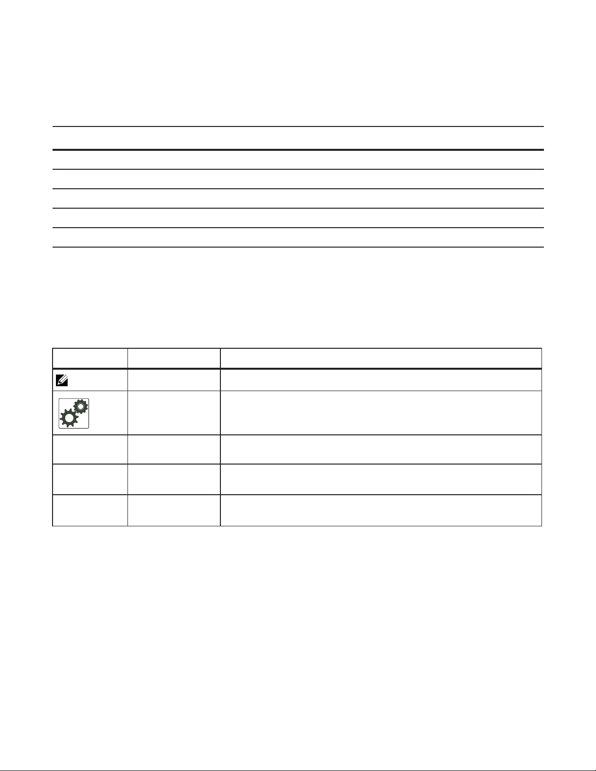
Conventions
This document uses the following conventions to describe command syntax:
Convention Description
keyword
parameter
{X} Keywords and parameters within braces must be entered in the CLI.
[X] Keywords and parameters within brackets are optional.
www.dell.com | support.dell.com
x | y Keywords and parameters separated by bar require you to choose one.
Keywords are in bold and should be entered in the CLI as listed.
Parameters are in italics and require a number or word to be entered in the CLI.
Information Symbols
Table 1-1 describes symbols contained in this guide.
Table 1-1. Information Symbols
Symbol Warning Description
Note This symbol informs you of important operational information.
FTOS Behavior This symbol informs you of an FTOS behavior. These behaviors are inherent to
the Dell Force10 system or FTOS feature and are non-configurable.
ces
et e
Platform Specific
Feature
E-Series Specific
x
Feature/Command
Exception This symbol is a note associated with some other text on the page that is marked
Related Documents
For more information about the Dell Force10 E-Series, C-Series, and S-Series refer to the following
documents:
• FTOS Command Reference
• Installing and Maintaining the S60 System
• FTOS Release Notes
This symbol informs you of a feature that supported on one or two platforms
only: e is for E-Series, c is for C-Series, s is for S-Series.
If a feature or command applies to only one of the E-Series platforms, a separate
symbol calls this to attention: e
with an asterisk.
for the TeraScale or e x for the ExaScale.
t
24 | About this Guide
Page 25

Configuration Fundamentals
The FTOS Command Line Interface (CLI) is a text-based interface through which you can configure
interfaces and protocols. The CLI is largely the same for the E-Series, C-Series, and S-Series with the
exception of some commands and command outputs. The CLI is structured in modes for security and
management purposes. Different sets of commands are available in each mode, and you can limit user
access to modes using privilege levels.
In FTOS, after a command is enabled, it is entered into the running configuration file. You can view the
current configuration for the whole system or for a particular CLI mode. To save the current configuration
copy the running configuration to another location.
Note: Due to a differences in hardware architecture and the continued system development, features may
occasionally differ between the platforms. These differences are identified by the information symbols
shown on Table 1-1 on page 24.
2
Accessing the Command Line
Access the command line through a serial console port or a Telnet session (Figure 2-1). When the system
successfully boots, you enter the command line in the EXEC mode.
Note: You must have a password configured on a virtual terminal line before you can Telnet into the
system. Therefore, you must use a console connection when connecting to the system for the first time.
Figure 2-1. Logging into the System using Telnet
telnet 172.31.1.53
Trying 172.31.1.53...
Connected to 172.31.1.53.
Escape character is '^]'.
Login: username
Password:
EXEC mode prompt
Configuration Fundamentals | 25
Page 26

CLI Modes
Different sets of commands are available in each mode. A command found in one mode cannot be
executed from another mode (with the exception of EXEC mode commands preceded by the command
see The do Command on page 30). You can set user access rights to commands and command modes using
privilege levels; for more information on privilege levels and security options, refer to Chapter 9, Security,
on page 627.
The FTOS CLI is divided into three major mode levels:
• EXEC mode is the default mode and has a privilege level of 1, which is the most restricted level. Only
a limited selection of commands is available, notably
system information.
www.dell.com | support.dell.com
• EXEC Privilege mode has commands to view configurations, clear counters, manage configuration
files, run diagnostics, and enable or disable debug operations. The privilege level is 15, which is
unrestricted. You can configure a password for this mode; see Configure the Enable Password on
page 43.
• CONFIGURATION mode enables you to configure security features, time settings, set logging and
SNMP functions, configure static ARP and MAC addresses, and set line cards on the system.
Beneath CONFIGURATION mode are sub-modes that apply to interfaces, protocols, and features.
Figure 2-2 illustrates this sub-mode command structure. Two sub-CONFIGURATION modes are
important when configuring the chassis for the first time:
do;
show commands, which allow you to view
• INTERFACE sub-mode is the mode in which you configure Layer 2 and Layer 3 protocols and IP
services specific to an interface. An interface can be physical (Management interface, 1-Gigabit
Ethernet, or 10-Gigabit Ethernet, or SONET) or logical (Loopback, Null, port channel, or VLAN).
• LINE sub-mode is the mode in which you to configure the console and virtual terminal lines.
Note: At any time, entering a question mark (?) will display the available command options. For example,
when you are in CONFIGURATION mode, entering the question mark first will list all available commands,
including the possible sub-modes.
26 | Configuration Fundamentals
Page 27

Figure 2-2. CLI Modes in FTOS
EXEC
EXEC Privilege
CONFIGURATION
ARCHIVE
AS-PATH ACL
INTERFACE
GIGABIT ETHERNET
10 GIGABIT ETHERNET
INTERFACE RANGE
LOOPBACK
MANAGEMENT ETHERNET
NULL
PORT-CHANNEL
SONET
VLAN
VRRP
IP
IPv6
IP COMMUNITY-LIST
IP ACCESS-LIST
STANDARD ACCESS-LIST
EXTENDED ACCESS-LIST
LINE
AUXILIARY
CONSOLE
VIRTUAL TERMINAL
MAC ACCESS-LIST
MONITOR SESSION
MULTIPLE SPANNING TREE
Per-VLAN SPANNING TREE
PREFIX-LIST
RAPID SPANNING TREE
REDIRECT
ROUTE-MAP
ROUTER BGP
ROUTER ISIS
ROUTER OSPF
ROUTER RIP
SPANNING TREE
TRACE-LIST
Navigating CLI Modes
The FTOS prompt changes to indicate the CLI mode. Table 2-1 lists the CLI mode, its prompt, and
information on how to access and exit this CLI mode. You must move linearly through the command
modes, with the exception of the
command moves you up one command mode level.
Note: Sub-CONFIGURATION modes all have the letters “conf” in the prompt with additional modifiers to
identify the mode and slot/port information. These are shown in Table 2-1.
end command which takes you directly to EXEC Privilege mode; the exit
Configuration Fundamentals | 27
Page 28

Table 2-1. FTOS Command Modes
CLI Command Mode Prompt
EXEC
EXEC Privilege
CONFIGURATION
www.dell.com | support.dell.com
Note: Access all of the following modes from CONFIGURATION mode.
ARCHIVE Force10(conf-archive)
AS-P ATH ACL Force10(config-as-path)#
Gigabit Ethernet
Interface
10 Gigabit Ethernet
Interface
Interface Range Force10(conf-if-range)#
Loopback Interface Force10(conf-if-lo-0)#
Management Ethernet
Interface
Force10>
Force10#
Force10(conf)#
Force10(conf-if-gi-0/0)#
Force10(conf-if-te-0/0)#
Force10(conf-if-ma-0/0)#
Access Command
Access the router through the console or Telnet.
• From EXEC mode, enter the command enable.
• From any other mode, use the command end.
• From EXEC privilege mode, enter the command
configure.
• From every mode except EXEC and EXEC
Privilege, enter the command
archive
ip as-path access-list
interface
exit.
Null Interface Force10(conf-if-nu-0)#
INTERFACE modes
Port-channel Interface Force10(conf-if-po-0)#
SONET Interface Force10(conf-if-so-0/0)#
VLAN Interface Force10(conf-if-vl-0)#
STANDARD
Force10(config-std-nacl)#
ACCESS- LIST
EXTENDED
Force10(config-ext-nacl)#
ACCESS- LIST
IP ACCESS-LIST
IP
COMMUNITY-LIST
Force10(config-community-list
)#
AUXILIARY Force10(config-line-aux)#
CONSOLE Force10(config-line-console)#
LINE
VIRTUAL
Force10(config-line-vty)#
TERMINAL
ip access-list standard
ip access-list extended
ip community-list
line
28 | Configuration Fundamentals
Page 29

Table 2-1. FTOS Command Modes
CLI Command Mode Prompt
STANDARD
Force10(config-std-macl)#
ACCESS- LIST
EXTENDED
Force10(config-ext-macl)#
ACCESS- LIST
MAC ACCESS-LIST
MULTIPLE
Force10(config-mstp)#
SPANNING TREE
Per-VLAN
Force10(config-pvst)#
SPANNING TREE
Plus
PREFIX-LIST Force10(conf-nprefixl)#
RAPID SPANNING
Force10(config-rstp)#
TREE
REDIRECT Force10(conf-redirect-list)#
ROUTE-MAP Force10(config-route-map)#
Access Command
mac access-list standard
mac access-list extended
protocol spanning-tree mstp
protocol spanning-tree pvst
ip prefix-list
protocol spanning-tree rstp
ip redirect-list
route-map
ROUTER BGP Force10(conf-router_bgp)#
ROUTER ISIS Force10(conf-router_isis)#
ROUTER OSPF Force10(conf-router_ospf)#
ROUTER RIP Force10(conf-router_rip)#
SPANNING TREE Force10(config-span)#
TRACE-LIST Force10(conf-trace-acl)#
router bgp
router isis
router ospf
router rip
protocol spanning-tree 0
ip trace-list
Figure 2-3 illustrates how to change the command mode from CONFIGURATION mode to PROTOCOL
SPANNING TREE.
Figure 2-3. Changing CLI Modes
Force10(conf)#protocol spanning-tree 0
Force10(config-span)#
New command prompt
Configuration Fundamentals | 29
Page 30
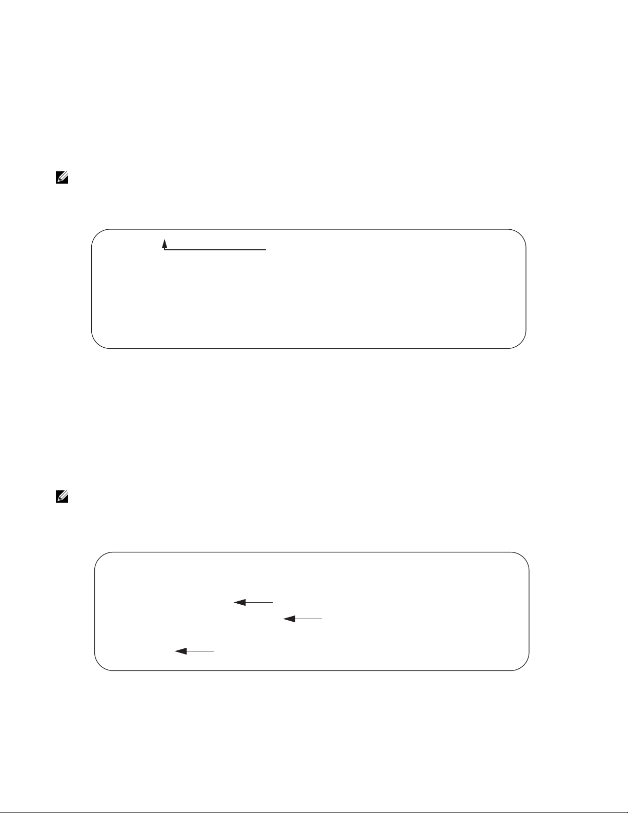
The do Command
Enter an EXEC mode command from any CONFIGURATION mode (CONFIGURATION, INTERFACE,
SPANNING TREE, etc.) without returning to EXEC mode by preceding the EXEC mode command with
the command
Note: The following commands cannot be modified by the do command: enable, disable, exit, and
configure.
Figure 2-4. Using the do Command
Force10(conf)#do show linecard all
www.dell.com | support.dell.com
-- Line cards -Slot Status NxtBoot ReqTyp CurTyp Version Ports
-------------------------------------------------------------------------- 0 not present
1 not present
2 online online E48TB E48TB 1-1-463 48
3 not present
4 not present
5 online online E48VB E48VB 1-1-463 48
do. Figure 2-4 illustrates the do command.
“do” form of show command
Undoing Commands
When you enter a command, the command line is added to the running configuration file. Disable a
command and remove it from the running-config by entering the original command preceded by the
command
ip-address
Note: Use the help or ? command as discussed in Obtaining Help command to help you construct the “no”
form of a command.
Figure 2-5. Undoing a command with the no Command
Force10(conf)#interface gigabitethernet 4/17
Force10(conf-if-gi-4/17)#ip address 192.168.10.1/24
Force10(conf-if-gi-4/17)#show config
!
interface GigabitEthernet 4/17
ip address 192.168.10.1/24
no shutdown
Force10(conf-if-gi-4/17)#no ip address
Force10(conf-if-gi-4/17)#show config
!
interface GigabitEthernet 4/17
Layer 2 protocols are disabled by default. Enable them using the no disable command. For example, in
PROTOCOL SPANNING TREE mode, enter
no. For example, to delete an ip address configured on an interface, use the no ip address
command, as shown in Figure 2-5.
IP address removed
IP address assigned
“no” form of IP address command
no disable to enable Spanning Tree.
30 | Configuration Fundamentals
Page 31

Obtaining Help
Obtain a list of keywords and a brief functional description of those keywords at any CLI mode using the ?
help command:
or
• Enter
? at the prompt or after a keyword to list the keywords available in the current mode.
•
? after a prompt lists all of the available keywords. The output of this command is the same for the
help command.
Figure 2-6. ? Command Example
Force10#?
calendar Manage the hardware calendar
cd Change current directory
change Change subcommands
clear Reset functions
clock Manage the system clock
configure Configuring from terminal
copy Copy from one file to another
debug Debug functions
--More--
“?” at prompt for list of commands
• ? after a partial keyword lists all of the keywords that begin with the specified letters.
Figure 2-7. Keyword? Command Example
Force10(conf)#cl?
class-map
clock
Force10(conf)#cl
partial keyword plus “[space]?” for matching keywords
• A keyword followed by [space]? lists all of the keywords that can follow the specified keyword.
Figure 2-8. Keyword ? Command Example
Force10(conf)#clock ?
summer-time Configure summer (daylight savings) time
timezone Configure time zone
Force10(conf)#clock
keyword plus “[space]?” for compatible keywords
Entering and Editing Commands
When entering commands:
• The CLI is not case sensitive.
• You can enter partial CLI keywords.
• You must enter the minimum number of letters to uniquely identify a command. For example,
cannot be entered as a partial keyword because both the clock and class-map commands begin with
the letters “cl.”
begins with those three letters.
• The TAB key auto-completes keywords in commands. You must enter the minimum number of letters
to uniquely identify a command.
clo, however, can be entered as a partial keyword because only one command
cl
Configuration Fundamentals | 31
Page 32

• The UP and DOWN arrow keys display previously entered commands (see Command History).
• The BACKSPACE and DELETE keys erase the previous letter.
• Key combinations are available to move quickly across the command line, as described in Table 2-2.
Table 2-2. Short-Cut Keys and their Actions
Key Combination Action
CNTL-A Moves the cursor to the beginning of the command line.
CNTL-B Moves the cursor back one character.
CNTL-D Deletes character at cursor.
CNTL-E Moves the cursor to the end of the line.
CNTL-F Moves the cursor forward one character.
www.dell.com | support.dell.com
CNTL-I Completes a keyword.
CNTL-K Deletes all characters from the cursor to the end of the command line.
CNTL-L Re-enters the previous command.
CNTL-N Return to more recent commands in the history buffer after recalling commands with CTRL-P or the
UP arrow key.
CNTL-P Recalls commands, beginning with the last command
CNTL-R Re-enters the previous command.
CNTL-U Deletes the line.
CNTL-W Deletes the previous word.
CNTL-X Deletes the line.
CNTL-Z Ends continuous scrolling of command outputs.
Esc B Moves the cursor back one word.
Esc F Moves the cursor forward one word.
Esc D Deletes all characters from the cursor to the end of the word.
Command History
FTOS maintains a history of previously-entered commands for each mode. For example:
• When you are in EXEC mode, the UP and DOWN arrow keys display the previously-entered EXEC
mode commands.
• When you are in CONFIGURATION mode, the UP or DOWN arrows keys recall the
previously-entered CONFIGURATION mode commands.
32 | Configuration Fundamentals
Page 33

Filtering show Command Outputs
Filter the output of a show command to display specific information by adding | [except | find | grep |
no-more | save
filtering and it IS case sensitive unless the
] specified_text after the command. The variable specified_text is the text for which you are
ignore-case sub-option is implemented.
Starting with FTOS 7.8.1.0, the
grep command accepts an ignore-case sub-option that forces the search to
case-insensitive. For example, the commands:
• show run | grep Ethernet returns a search result with instances containing a capitalized “Ethernet,”
such as interface GigabitEthernet 0/0.
•
show run | grep ethernet would not return that search result because it only searches for instances
containing a non-capitalized “ethernet.”
Executing the command
show run | grep Ethernet ignore-case would return instances containing both
“Ethernet” and “ethernet.”
grep displays only the lines containing specified text. Figure 2-9 shows this command used in
•
combination with the command
show linecard all.
Figure 2-9. Filtering Command Outputs with the grep Command
Force10(conf)#do show linecard all | grep 0
0 not present
Note: FTOS accepts a space or no space before and after the pipe. To filter on a phrase with spaces,
underscores, or ranges, enclose the phrase with double quotation marks.
• except displays text that does not match the specified text. Figure 2-10 shows this command used in
combination with the command
show linecard all.
Figure 2-10. Filtering Command Outputs with the except Command
Force10#show linecard all | except 0
-- Line cards -Slot Status NxtBoot ReqTyp CurTyp Version Ports
-------------------------------------------------------------------------- 2 not present
3 not present
4 not present
5 not present
6 not present
Configuration Fundamentals | 33
Page 34

• find displays the output of the show command beginning from the first occurrence of specified text
Figure 2-11 shows this command used in combination with the command
Figure 2-11. Filtering Command Outputs with the find Command
Force10(conf)#do show linecard all | find 0
0 not present
1 not present
2 online online E48TB E48TB 1-1-463 48
3 not present
4 not present
5 online online E48VB E48VB 1-1-463 48
6 not present
7 not present
show linecard all.
www.dell.com | support.dell.com
• display displays additional configuration information.
•
no-more displays the output all at once rather than one screen at a time. This is similar to the command
terminal length except that the no-more option affects the output of the specified command only.
•
save copies the output to a file for future reference.
Note: You can filter a single command output multiple times. The save option should be the last option
entered. For example:
Force10# command | grep regular-expression | except regular-expression | grep
other-regular-expression | find regular-expression | save
Multiple Users in Configuration mode
FTOS notifies all users in the event that there are multiple users logged into CONFIGURATION mode. A
warning message indicates the username, type of connection (console or vty), and in the case of a vty
connection, the IP address of the terminal on which the connection was established. For example:
• On the system that telnets into the switch, Message 1 appears:
Message 1 Multiple Users in Configuration mode Telnet Message
% Warning: The following users are currently configuring the system:
User "<username>" on line console0
• On the system that is connected over the console, Message 2 appears:
Message 2 Multiple Users in Configuration mode Telnet Message
% Warning: User "<username>" on line vty0 "10.11.130.2" is in configuration mode
If either of these messages appears, Dell Force10 recommends that you coordinate with the users listed in
the message so that you do not unintentionally overwrite each other’s configuration changes.
34 | Configuration Fundamentals
Page 35

Getting Started
This chapter contains the following major sections:
• Default Configuration on page 39
• Configure a Host Name on page 40
• Access the System Remotely on page 40
• Configure the Enable Password on page 43
• Configuration File Management on page 43
• File System Management on page 48
When you power up the chassis, the system performs a Power-On Self Test (POST) during which Route
Processor Module (RPM), Switch Fabric Module (SFM), and line card status LEDs blink green.The
system then loads FTOS and boot messages scroll up the terminal window during this process. No user
interaction is required if the boot process proceeds without interruption.
3
When the boot process is complete, the RPM and line card status LEDs remain online (green), and the
console monitor displays the Force10 banner and EXEC mode prompt, as shown in Figure 3-1.
For details on using the Command Line Interface (CLI), see the Accessing the Command Line section in
Chapter 1, Configuration Fundamentals, on page 47.
Console access
The S60 has 2 management ports available for system access: a serial console port and a USB-B port. The
USB-B ports acts exactly as the console port.
By default, the S60 sends system messages to the serial console port. However, only one console
connection can be active at a time. When both the serial console port and the USB-B port are connected,
the system defaults to the USB-B port. The console connection is considered inactive if the USB-B port is
also connected.
You can switch between console connections by physically connecting or disconnecting the cables. A
system message is displayed on the serial console prior to switching to the USB-B console. When the
USB-B cable is detached, the system returns to the serial console default.
Getting Started | 35
Page 36

Serial console
The RS-232 console port is labeled on the S60 chassis. It is in the upper right-hand side, as you face the
rear of the chassis.
Console
Port
www.dell.com | support.dell.com
To access the console port, follow the procedures below. Refer to Table 3-1 for the console port pinout.
Step Task
1 Install an RJ-45 copper cable into the console port.Use a rollover (crossover) cable to connect the S60 console
port to a terminal server.
2 Connect the other end of the cable to the DTE terminal server.
3 Terminal settings on the console port cannot be changed in the software and are set as follows:
9600 baud rate
No parity
8 data bits
1 stop bit
No flow control
Accessing the RJ-45 console port with a DB-9 adapter
You can connect to the console using a RJ-45 to RJ-45 rollover cable and a RJ-45 to DB-9 female DTE
adapter to a terminal server (for example, PC). Table 3-1 lists the pin assignments.
Table 3-1. Pin Assignments Between the E-Series Console and a DTE Terminal Server
E-Series
Console Port RJ-45 to RJ-45 Rollover Cable
Signal RJ-45 pinout RJ-45 Pinout DB-9 Pin Signal
RTS 1 8 8 CTS
NC 2 7 6 DSR
TxD 3 6 2 RxD
GND 4 5 5 GND
GND 5 4 5 GND
RxD 6 3 3 TxD
36 | Getting Started
RJ-45 to DB-9
Adapter
Terminal Server
Device
Page 37

Table 3-1. Pin Assignments Between the E-Series Console and a DTE Terminal Server (continued)
E-Series
Console Port RJ-45 to RJ-45 Rollover Cable
Signal RJ-45 pinout RJ-45 Pinout DB-9 Pin Signal
NC 7 2 4 DTR
CTS 8 1 7 RTS
RJ-45 to DB-9
Adapter
Terminal Server
Device
USB-B console
The USB-B connector port is labeled on the the S60 chassis. It is to the left of the management ports, as
you face the rear of the chassis
USB-B
Port
Step Task
1 Power on the PC (XP operating system recommended)
2 Connect the USB-A end of cable (supplied) into an available USB port on the PC
3 Connect the USB-B end of cable into the USB-B console port on the S60 (see Figure 7)
4 Power on the S60.
5 Install necessary USB device drivers (internet connection required).
Contact Dell Force10 TAC for CD, if necessary.
6 Open your terminal software emulation program to access the S60.
Getting Started | 37
Page 38

Step Task (continued)
7 Using the terminal settings shown here, set the terminal connection settings.
• 9600 baud rate, No parity, 8 data bits, 1 stop bit, No flow control
www.dell.com | support.dell.com
8 You will see the message below when you are connected to the S60.
38 | Getting Started
Page 39

Figure 3-1. Completed Boot Process
o
.*************.
.# #### #######.
######## ####### ######### ######## ######## .#. ###### ###########.
### ### ## ### ### #### ### .##. ## ### #### ###.
### ### ### ### ### ### ### *#. ### ### #*
### ### ## ### #### ### ######## *# -## ### #*
###### ### ## ######### ### ######## *# ### ## #*
### ### ## ### #### ### ### *# #### ### #*
### ### ### ### #### #### ### *#. #### ### ###*
### ### ### ### ### ##### ## ######## .#.##### #### #### .
### ##### ### ### ###### ######## .###### ############ .
.# ######### .
`************'
Copyright 1999-2006 Force10 Networks, Inc.
+ Force10 Networks, Inc.
+ CPU: DB-MV64460-BP/IBM750Fx (2.3)
+ Version: VxWorks5.5.1
+ Memory Size: 1038876672 bytes.
+ BSP Version: 1.2/1.3.6
+ Creation Date : Jan 2 2007
nvDrvInit: nvDrvErase passed
-> 00:00:10: %RPM0-U:CP %RAM-6-ELECTION_ROLE: RPM0 is transitioning to Primary RPM.
00:00:11: %RPM0-P:CP %CHMGR-2-FAN_BAD: Minor alarm: some fans in fan tray 0 are down
00:00:11: %RPM0-P:CP %CHMGR-5-CARDDETECTED: Line card 1 present
DSA Card Init
00:00:11: %RPM0-P:CP POEMGR-4-POE_POWER_USAGE_ABOVE_THRESHOLD: Inline power used is exceeded 90%
available inline power
00:00:12: %RPM0-P:CP %CHMGR-5-CARDDETECTED: Line card 2 present
00:00:12: %RPM0-P:CP %TSM-6-SFM_SWITCHFAB_STATE: Switch Fabric: UP
00:00:12: %RPM0-P:CP %TSM-6-SFM_FULL_PARTIAL_STATE: SW_FAB_UP_1 SFM in the system
00:00:13: %RPM0-P:CP %IFMGR-5-OSTATE_UP: Changed interface state to up: Ma 0/0
00:01:27: %RPM0-P:CP %CHMGR-5-CHECKIN: Checkin from line card 1 (type E48TB, 48 ports)
00:01:27: %RPM0-P:CP %CHMGR-5-CHECKIN: Checkin from line card 2 (type E48TB, 48 ports)
00:01:28: %RPM0-P:CP %CHMGR-5-LINECARDUP: Line card 1 is up
00:01:28: %RPM0-P:CP %CHMGR-5-LINECARDUP: Line card 2 is up
00:01:36: %RPM0-P:CP %RAM-5-RPM_STATE: RPM0 is in Active State.
00:01:36: %RPM0-P:CP %CHMGR-5-CHAS_READY: Chassis ready
00:01:37: %RPM0-P:CP %SEC-5-LOGIN_SUCCESS: Login successful for user on line console
Force10>
Default Configuration
A version of FTOS is pre-loaded onto the chassis, however the system is not configured when you power
up for the first time (except for the default hostname, which is Force10). You must configure the system
using the CLI.
Getting Started | 39
Page 40

Configure a Host Name
The host name appears in the prompt. The default host name is force10.
• Host names must start with a letter and end with a letter or digit.
• Characters within the string can be letters, digits, and hyphens.
To configure a host name:
Step Task Command Syntax Command Mode
www.dell.com | support.dell.com
1 Create a new host name.
Figure 3-2 illustrates the hostname command.
Figure 3-2. Configuring a Hostname
Default Hostname
Force10(conf)#hostname R1
R1(conf)#
New Hostname
Access the System Remotely
You can configure the system to access it remotely by Telnet. The method for configuring the C-Series and
E-Series for Telnet access is different from S-Series.
• The C-Series, E-Series and the S60 have a dedicated management port and a management routing table
that is separate from the IP routing table.
• The S-Series (except the S60) does not have a dedicated management port, but is managed from any
port. It does not have a separate management routing table.
hostname name
CONFIGURATION
Access the C-Series and E-Series and the S60 Remotely
Configuring the system for Telnet is a three-step process:
1. Configure an IP address for the management port. See Configure the Management Port IP Address.
2. Configure a management route with a default gateway. See Configure a Management Route.
3. Configure a username and password. See Configure a Username and Password.
40 | Getting Started
Page 41

Configure the Management Port IP Address
Assign IP addresses to the management ports in order to access the system remotely.
Note: Assign different IP addresses to each RPM’s management port.
To configure the management port IP address:
Step Task Command Syntax Command Mode
1 Enter INTERFACE mode for the
Management port.
2
3
Assign an IP address to the
interface.
Enable the interface.
interface ManagementEthernet slot/port
• slot range: 0 to 1
• port range: 0
ip address ip-address/mask
• ip-address: an address in dotted-decimal format
(A.B.C.D).
• mask: a subnet mask in /prefix-length format (/
xx).
no shutdown
CONFIGURATION
INTERFACE
INTERFACE
Configure a Management Route
Define a path from the system to the network from which you are accessing the system remotely.
Management routes are separate from IP routes and are only used to manage the system through the
management port.
To configure a management route:
Step Task Command Syntax Command Mode
Configure a management route to
1
the network from which you are
accessing the system.
management route ip-address/mask gateway
• ip-address: the network address in
dotted-decimal format (A.B.C.D).
• mask: a subnet mask in /prefix-length format (/
xx).
• gateway: the next hop for network traffic
originating from the management port.
Configure a Username and Password
Configure a system username and password to access the system remotely.
CONFIGURATION
Getting Started | 41
Page 42

To configure a username and password:
Step Task Command Syntax Command Mode
Configure a username and
1
password to access the system
remotely.
www.dell.com | support.dell.com
Access the S-Series Remotely
The S-Series does not have a dedicated management port nor a separate management routing table.
Configure any port on the S-Series to be the port through which you manage the system and configure an
IP route to that gateway.
Note: The S60 system uses management ports and should be configured similar to the C-Series and
E-Series systems. Refer to Access the C-Series and E-Series and the S60 Remotely
Configuring the system for Telnet access is a three-step process:
1. Configure an IP address for the port through which you will manage the system using the command
address
from INTERFACE mode, as shown in Figure 3-3.
username username password [encryption-type]
password
encryption-type
specifies how you are inputting the
password, is 0 by default, and is not required.
• 0 is for inputting the password in clear text.
• 7 is for inputting a password that is already
encrypted using a Type 7 hash. Obtaining the
encrypted password from the configuration of
another Dell Force10 system.
CONFIGURATION
ip
2. Configure a IP route with a default gateway using the command
mode, as shown in Figure 3-3.
3. Configure a username and password using the command
username from CONFIGURATION mode, as
shown in Figure 3-3.
Figure 3-3. Configuring the S-Series for Remote Access
R5(conf)#int gig 0/48
R5(conf-if-gi-0/48)#ip address 10.11.131.240
R5(conf-if-gi-0/48)#show config
!
interface GigabitEthernet 0/48
ip address 10.11.131.240/24
no shutdown
R5(conf-if-gi-0/48)#exit
R5(conf)#ip route 10.11.32.0/23 10.11.131.254
R5(conf)#username admin pass force10
ip route from CONFIGURATION
42 | Getting Started
Page 43

Configure the Enable Password
Access the EXEC Privilege mode using the enable command. The EXEC Privilege mode is unrestricted by
default. Configure a password as a basic security measure. There are two types of
enable password stores the password in the running/startup configuration using a DES encryption
•
method.
enable secret is stored in the running/startup configuration in using a stronger, MD5 encryption
•
method.
enable passwords:
Dell Force10 recommends using the
enable secret password.
To configure an enable password:
Task Command Syntax Command Mode
Create a password to
access EXEC Privilege
mode.
enable [password | secret] [level level] [encryption-type]
password
level
is the privilege level, is 15 by default, and is not required.
encryption-type specifies how you are inputting the password, is 0 by
default, and is not required.
• 0 is for inputting the password in clear text.
• 7 is for inputting a password that is already encrypted using a
DES hash. Obtain the encrypted password from the configuration
file of another Dell Force10 system.
• 5 is for inputting a password that is already encrypted using an
MD5 hash. Obtain the encrypted password from the configuration
file of another Dell Force10 system.
CONFIGURATION
Configuration File Management
Files can be stored on and accessed from various storage media. Rename, delete, and copy files on the
system from the EXEC Privilege mode.
The E-Series TeraScale and ExaScale platforms architecture use Compact Flash for the internal and
external Flash memory. It has a space limitation but does not limit the number of files it can contain.
Note: Using flash memory cards in the system that have not been approved by Dell Force10 can cause
unexpected system behavior, including a reboot.
Getting Started | 43
Page 44

Copy Files to and from the System
The command syntax for copying files is similar to UNIX. The copy command uses the format copy
source-file-url destination-file-url
Note: See the FTOS Command Reference for a detailed description of the copy command.
• To copy a local file to a remote system, combine the file-origin syntax for a local file location with the
file-destination syntax for a remote file location shown in Table 3-2.
• To copy a remote file to Dell Force10 system, combine the
with the
www.dell.com | support.dell.com
Table 3-2. Forming a copy Command
Local File Location
Internal flash:
file-destination syntax for a local file location shown in Table 3-2.
source-file-url Syntax destination-file-url Syntax
.
file-origin syntax for a remote file location
primary RPM
standby RPM copy rpm{0|1}flash://filename rpm{0|1}flash://filename
External flash:
primary RPM copy rpm{0|1}slot0://filename rpm{0|1}slot0://filename
standby RPM copy rpm{0|1}slot0://filename rpm{0|1}slot0://filename
USB Drive (E-Series ExaScale and S60)
USB drive on RPM0
External USB drive
Remote File Location
FTP server copy ftp://username:password@{hostip |
TFTP server copy tftp://{hostip | hostname}/filepath/
SCP server copy scp://{hostip | hostname}/filepath/
copy flash://filename flash://filename
copy rpm0usbflash://filepath rpm0usbflash://filename
copy usbflash://filepath
hostname
filename
filename
}/filepath/filename
usbflash://filename
ftp://username:password
filepath/filename
tftp://{hostip | hostname}/filepath/filename
scp://{hostip | hostname}/filepath/filename
Important Points to Remember
• You may not copy a file from one remote system to another.
• You may not copy a file from one location to the same location.
• The internal flash memories on the RPMs are synchronized whenever there is a change, but only if
both RPMs are running the same version of FTOS.
• When copying to a server, a hostname can only be used if a DNS server is configured.
• The
usbflash and rpm0usbflash commands are supported on E-Series ExaScale and S60 systems.
Refer to your system’s Release Notes for a list of approved USB vendors.
@{hostip | hostname}/
44 | Getting Started
Page 45

Figure 3-4 shows an example of using the copy command to save a file to an FTP server.
Figure 3-4. Saving a file to a Remote System
Local Location
Remote Location
Force10#copy flash://FTOS-EF-8.2.1.0.bin ftp://myusername:mypassword@10.10.10.10//FTOS/FTOS-EF-8.2.1.0
!!!!!!!!!!!!!!!!!!!!!!!!!!!!!!!!!!!!!!!!!!!!!!!!!!!!!!!!!!!!!!!!!!!!!!!!!!!!!
27952672 bytes successfully copied
Figure 3-5 shows an example of using the copy command to import a file to the Dell Force10 system from
an FTP server.
Figure 3-5. Saving a file to a Remote System
Remote Location
Local Location
core1#$//copy ftp://myusername:mypassword@10.10.10.10//FTOS/FTOS-EF-8.2.1.0.bin flash://
Destination file name [FTOS-EF-8.2.1.0.bin.bin]:
!!!!!!!!!!!!!!!!!!!!!!!!!!!!!!!!!!!!!!!!!!!!!!!!!!!!!!!!!!!!!!!!
26292881 bytes successfully copied
Save the Running-configuration
The running-configuration contains the current system configuration. Dell Force10 recommends that you
copy your running-configuration to the startup-configuration. The system uses the startup-configuration
during boot-up to configure the system. The startup-configuration is stored in the internal flash on the
primary RPM by default, but it can be saved onto an external flash (on an RPM) or a remote server.
To save the running-configuration:
Note: The commands in this section follow the same format as those in Copy Files to and from the
System on page 44 but use the filenames startup-configuration and running-configuration. These
commands assume that current directory is the internal flash, which is the system default.
Getting Started | 45
Page 46

Task Command Syntax Command Mode
Save the running-configuration to:
the startup-configuration on the
internal flash of the primary RPM
the internal flash on an RPM copy running-config rpm{0|1}flash://filename
Note: The internal flash memories on the RPMs are synchronized whenever there
is a change, but only if the RPMs are running the same version of FTOS.
the external flash of an RPM copy running-config rpm{0|1}slot0://filename
www.dell.com | support.dell.com
an FTP server
a TFTP server copy running-config tftp://{hostip | hostname}/
an SCP server copy running-config scp://{hostip | hostname}/
Note: When copying to a server, a hostname can only be used if a DNS server is configured.
Save the running-configuration to the
startup-configuration on the internal flash
of the primary RPM. Then copy the new
startup-config file to the external flash of
the primary RPM.
copy running-config startup-config
copy running-config ftp://
username:password
filename
filepath/filename
filepath/filename
copy running-config startup-config duplicate
@{hostip | hostname}/filepath/
EXEC Privilege
EXEC Privilege
FTOS Behavior: If you create a startup-configuration on an RPM and then move the RPM to another
chassis, the startup-configuration is stored as a backup file (with the extension .bak), and a new,
empty startup-configuration file is created. To restore your original startup-configuration in this
situation, overwrite the new startup-configuration with the original one using the command copy
startup-config.bak startup-config.
View Files
File information and content can only be viewed on local file systems.
To view a list of files on the internal or external Flash:
Step Task Command Syntax Command Mode
1 View a list of files on:
46 | Getting Started
the external flash of an RPM
dir flash:
dir slot:
EXEC Privilegethe internal flash of an RPM
Page 47

The output of the command dir also shows the read/write privileges, size (in bytes), and date of
modification for each file, as shown in Figure 3-6.
Figure 3-6. Viewing a List of Files in the Internal Flash
Force10#dir
Directory of flash:
1 drw- 32768 Jan 01 1980 00:00:00 .
2 drwx 512 Jul 23 2007 00:38:44 ..
3 drw- 8192 Mar 30 1919 10:31:04 TRACE_LOG_DIR
4 drw- 8192 Mar 30 1919 10:31:04 CRASH_LOG_DIR
5 drw- 8192 Mar 30 1919 10:31:04 NVTRACE_LOG_DIR
6 drw- 8192 Mar 30 1919 10:31:04 CORE_DUMP_DIR
7 d--- 8192 Mar 30 1919 10:31:04 ADMIN_DIR
8 -rw- 33059550 Jul 11 2007 17:49:46 FTOS-EF-7.4.2.0.bin
9 -rw- 27674906 Jul 06 2007 00:20:24 FTOS-EF-4.7.4.302.bin
10 -rw- 27674906 Jul 06 2007 19:54:52 boot-image-FILE
11 drw- 8192 Jan 01 1980 00:18:28 diag
12 -rw- 7276 Jul 20 2007 01:52:40 startup-config.bak
13 -rw- 7341 Jul 20 2007 15:34:46 startup-config
14 -rw- 27674906 Jul 06 2007 19:52:22 boot-image
15 -rw- 27674906 Jul 06 2007 02:23:22 boot-flash
--More--
To view the contents of a file:
Step Task Command Syntax Command Mode
1 View the:
contents of a file in the internal flash of
show file rpm{0|1}flash://filename
an RPM
contents of a file in the external flash
show file rpm{0|1}slot0://filename
EXEC Privilege
of an RPM
running-configuration
startup-configuration
show running-config
show startup-config
View Configuration Files
Configuration files have three commented lines at the beginning of the file, as shown in Figure 3-7, to help
you track the last time any user made a change to the file, which user made the changes, and when the file
was last saved to the startup-configuration.
In the running-configuration file, if there is a difference between the timestamp on the “Last configuration
change,” and “Startup-config last updated,” then you have made changes that have not been saved and will
not be preserved upon a system reboot.
Getting Started | 47
Page 48

Figure 3-7. Tracking Changes with Configuration Comments
Force10#show running-config
Current Configuration ...
! Version 8.2.1.0
! Last configuration change at Thu Apr 3 23:06:28 2008 by admin
! Startup-config last updated at Thu Apr 3 23:06:55 2008 by admin
!
boot system rpm0 primary flash://FTOS-EF-8.2.1.0.bin
boot system rpm0 secondary flash://FTOS-EF-7.8.1.0.bin
boot system rpm0 default flash://FTOS-EF-7.7.1.1.bin
boot system rpm1 primary flash://FTOS-EF-7.8.1.0.bin
boot system gateway 10.10.10.100
--More--
www.dell.com | support.dell.com
File System Management
The Dell Force10 system can use the internal Flash, external Flash, or remote devices to store files. It
stores files on the internal Flash by default but can be configured to store files elsewhere.
To view file system information:
Task Command Syntax Command Mode
View information about each file system.
The output of the command
show file-systems (Figure 3-8) shows the total capacity, amount of free
show file-systems
EXEC Privilege
memory, file structure, media type, read/write privileges for each storage device in use.
Figure 3-8. show file-systems Command Example
Force10#show file-systems
Size(b) Free(b) Feature Type Flags Prefixes
520962048 213778432 dosFs2.0 USERFLASH rw flash:
127772672 21936128 dosFs2.0 USERFLASH rw slot0:
- - - network rw ftp:
- - - network rw tftp:
- - - network rw scp:
You can change the default file system so that file management commands apply to a particular device or
memory.
To change the default storage location:
Task Command Syntax Command Mode
Change the default directory.
cd directory
EXEC Privilege
In Figure 3-9, the default storage location is changed to the external Flash of the primary RPM. File
management commands then apply to the external Flash rather than the internal Flash.
48 | Getting Started
Page 49

Figure 3-9. Alternative Storage Location
Force10#cd slot0:
Force10#copy running-config test
Force10#copy run test
!
7419 bytes successfully copied
Force10#dir
Directory of slot0:
1 drw- 32768 Jan 01 1980 00:00:00 .
2 drwx 512 Jul 23 2007 00:38:44 ..
3 ---- 0 Jan 01 1970 00:00:00 DCIM
4 -rw- 7419 Jul 23 2007 20:44:40 test
5 ---- 0 Jan 01 1970 00:00:00 BT
6 ---- 0 Jan 01 1970 00:00:00 200702~1VSN
7 ---- 0 Jan 01 1970 00:00:00 G
8 ---- 0 Jan 01 1970 00:00:00 F
9 ---- 0 Jan 01 1970 00:00:00 F
slot0: 127772672 bytes total (21927936 bytes free)
View command history
The command-history trace feature captures all commands entered by all users of the system with a time
stamp and writes these messages to a dedicated trace log buffer. The system generates a trace message for
each executed command. No password information is saved to the file.
No File System Specified
File Saved to External Flash
To view the command-history trace, use the
show command-history command, as shown in Figure 487.
Figure 3-10. Command Example show command-history
Force10#show command-history
[12/5 10:57:8]: CMD-(CLI):service password-encryption
[12/5 10:57:12]: CMD-(CLI):hostname Force10
[12/5 10:57:12]: CMD-(CLI):ip telnet server enable
[12/5 10:57:12]: CMD-(CLI):line console 0
[12/5 10:57:12]: CMD-(CLI):line vty 0 9
[12/5 10:57:13]: CMD-(CLI):boot system rpm0 primary flash://FTOS-CB-1.1.1.2E2.bin
Upgrading and Downgrading FTOS
Note: To upgrade or downgrade FTOS, see the release notes for the version you want to load on the
system.
Getting Started | 49
Page 50

www.dell.com | support.dell.com
50 | Getting Started
Page 51

Management
Management is supported on platforms: c e s
This chapter explains the different protocols or services used to manage the Dell Force10 system
including:
• Configure Privilege Levels on page 51
• Configure Logging on page 55
• File Transfer Services on page 62
• Terminal Lines on page 64
• Lock CONFIGURATION mode on page 68
• Recovering from a Forgotten Password on the S60 on page 69
• Recovering from a Failed Start on the S60 on page 71
4
Configure Privilege Levels
Privilege levels restrict access to commands based on user or terminal line. There are 16 privilege levels, of
which three are pre-defined. The default privilege level is 1.
• Level 0—Access to the system begins at EXEC mode, and EXEC mode commands are limited to
enable, disable, and exit.
• Level 1—Access to the system begins at EXEC mode, and all commands are available.
• Level 15—Access to the system begins at EXEC Privilege mode, and all commands are available.
Create a Custom Privilege Level
Custom privilege levels start with the default EXEC mode command set. You can then customize privilege
levels 2-14 by:
• restricting access to an EXEC mode command
• moving commands from EXEC Privilege to EXEC mode
• restricting access
A user can access all commands at his privilege level and below.
Management | 51
Page 52

Removing a command from EXEC mode
Remove a command from the list of available commands in EXEC mode for a specific privilege level
using the command
privilege exec from CONFIGURATION mode. In the command, specify a level greater
than the level given to a user or terminal line, followed by the first keyword of each command to be
restricted.
Move a command from EXEC privilege mode to EXEC mode
Move a command from EXEC Privilege to EXEC mode for a privilege level using the command privilege
exec
from CONFIGURATION mode. In the command, specify the privilege level of the user or terminal
line, and specify all keywords in the command to which you want to allow access.
www.dell.com | support.dell.com
Allow Access to CONFIGURATION mode commands
Allow access to CONFIGURATION mode using the command privilege exec level level configure from
CONFIGURATION mode. A user that enters CONFIGURATION mode remains at his privilege level, and
has access to only two commands,
mode command to which you want to allow access using the command
command, specify the privilege level of the user or terminal line, and specify all keywords in the command
to which you want to allow access.
end and exit. You must individually specify each CONFIGURATION
privilege configure level level. In the
Allow Access to INTERFACE, LINE, ROUTE-MAP, and ROUTER mode
1. Similar to allowing access to CONFIGURATION mode, to allow access to INTERFACE, LINE,
ROUTE-MAP, and ROUTER modes, you must first allow access to the command that enters you into
the mode. For example, allow a user to enter INTERFACE mode using the command
configure level level interface
gigabitethernet
2. Then, individually identify the INTERFACE, LINE, ROUTE-MAP or ROUTER commands to which
you want to allow access using the command
privilege {interface | line | route-map | router} level level.
In the command, specify the privilege level of the user or terminal line, and specify all keywords in the
command to which you want to allow access.
The following table lists the configuration tasks you can use to customize a privilege level:
Task Command Syntax Command Mode
Remove a command from the list of available commands
in EXEC mode.
Move a command from EXEC Privilege to EXEC mode. privilege exec level level
Allow access to CONFIGURATION mode. privilege exec level level
privilege exec level level
{command ||...|| command}
{command ||...|| command}
configure
privilege
CONFIGURATION
CONFIGURATION
CONFIGURATION
52 | Management
Page 53

Task Command Syntax Command Mode
Allow access to INTERFACE, LINE, ROUTE-MAP,
and/or ROUTER mode. Specify all keywords in the
command.
Allow access to a CONFIGURATION, INTERFACE,
LINE, ROUTE-MAP, and/or ROUTER mode command.
The configuration in Figure 4-1 creates privilege level 3. This level:
• removes the
• moves the command
resequence command from EXEC mode by requiring a minimum of privilege level 4,
capture bgp-pdu max-buffer-size from EXEC Privilege to EXEC mode by,
requiring a minimum privilege level 3, which is the configured level for VTY 0,
• allows access to CONFIGURATION mode with the
• allows access to INTERFACE and LINE modes are allowed with no commands.
privilege configure level level
{interface | line | route-map |
router} {command-keyword ||...||
command-keyword}
privilege {configure |interface |
line | route-map | router} level
level
{command ||...|| command}
banner command, and
CONFIGURATION
CONFIGURATION
Management | 53
Page 54

Figure 4-1. Create a Custom Privilege Level
Force10(conf)#do show run priv
!
privilege exec level 3 capture
privilege exec level 3 configure
privilege exec level 4 resequence
privilege exec level 3 capture bgp-pdu
privilege exec level 3 capture bgp-pdu max-buffer-size
privilege configure level 3 line
privilege configure level 3 interface
Force10(conf)#do telnet 10.11.80.201
[telnet output omitted]
Force10#show priv
Current privilege level is 3.
Force10#?
capture Capture packet
www.dell.com | support.dell.com
configure Configuring from terminal
disable Turn off privileged commands
enable Turn on privileged commands
exit Exit from the EXEC
ip Global IP subcommands
monitor Monitoring feature
mtrace Trace reverse multicast path from destination to source
ping Send echo messages
quit Exit from the EXEC
show Show running system information
[output omitted]
Force10#config
[output omitted]
Force10(conf)#do show priv
Current privilege level is 3.
Force10(conf)#?
end Exit from configuration mode
exit Exit from configuration mode
interface Select an interface to configure
line Configure a terminal line
linecard Set line card type
Force10(conf)#interface ?
fastethernet Fast Ethernet interface
gigabitethernet Gigabit Ethernet interface
loopback Loopback interface
managementethernet Management Ethernet interface
null Null interface
port-channel Port-channel interface
range Configure interface range
sonet SONET interface
tengigabitethernet TenGigabit Ethernet interface
vlan VLAN interface
Force10(conf)#interface gigabitethernet 1/1
Force10(conf-if-gi-1/1)#?
end Exit from configuration mode
exit Exit from interface configuration mode
Force10(conf-if-gi-1/1)#exit
Force10(conf)#line ?
aux Auxiliary line
console Primary terminal line
vty Virtual terminal
Force10(conf)#line vty 0
Force10(config-line-vty)#?
exit Exit from line configuration mode
Force10(config-line-vty)#
54 | Management
Page 55

Apply a Privilege Level to a Username
To set a privilege level for a user:
Task Command Syntax Command Mode
Configure a privilege level for a user.
username username privilege level
CONFIGURATION
Apply a Privilege Level to a Terminal Line
To set a privilege level for a terminal line:
Task Command Syntax Command Mode
Configure a privilege level for a terminal line.
Note: When you assign a privilege level between 2 and 15, access to the system begins at EXEC mode,
but the prompt is hostname#, rather than hostname>.
privilege level level
LINE
Configure Logging
FTOS tracks changes in the system using event and error messages. By default, FTOS logs these messages
on:
• the internal buffer
• console and terminal lines, and
• any configured syslog servers
Disable Logging
To disable logging:
Task Command Syntax Command Mode
Disable all logging except on the console.
Disable logging to the logging buffer.
Disable logging to terminal lines.
Disable console logging.
no logging on
no logging buffer CONFIGURATION
no logging monitor CONFIGURATION
no logging console CONFIGURATION
CONFIGURATION
Management | 55
Page 56

Log Messages in the Internal Buffer
All error messages, except those beginning with %BOOTUP (Message), are log in the internal buffer.
Message 1 BootUp Events
%BOOTUP:RPM0:CP %PORTPIPE-INIT-SUCCESS: Portpipe 0 enabled
Configuration Task List for System Log Management
The following list includes the configuration tasks for system log management:
www.dell.com | support.dell.com
• Disable System Logging on page 56
• Send System Messages to a Syslog Server on page 57
Disable System Logging
By default, logging is enabled and log messages are sent to the logging buffer, all terminal lines, console,
and syslog servers.
Enable and disable system logging using the following commands:
Task Command Syntax Command Mode
Disable all logging except on the console.
Disable logging to the logging buffer.
Disable logging to terminal lines.
Disable console logging.
no logging on
no logging buffer CONFIGURATION
no logging monitor CONFIGURATION
no logging console CONFIGURATION
CONFIGURATION
56 | Management
Page 57

Send System Messages to a Syslog Server
Send system messages to a syslog server by specifying the server with the following command:
Task Command Syntax Command Mode
Specify the server to which you want to send system
messages. You can configure up to eight syslog servers.
logging {ip-address | hostname} CONFIGURATION
Configure a Unix System as a Syslog Server
Configure a UNIX system as a syslog server by adding the following lines to /etc/syslog.conf on the Unix
system and assigning write permissions to the file.
• on a 4.1 BSD UNIX system, add the line: local7.debugging /var/log/force10.log
• on a 5.7 SunOS UNIX system, add the line: local7.debugging /var/adm/force10.log
In the lines above, local7 is the logging facility level and debugging is the severity level.
Change System Logging Settings
You can change the default settings of the system logging by changing the severity level and the storage
location. The default is to log all messages up to debug level, that is, all system messages. By changing the
severity level in the logging commands, you control the number of system messages logged.
Task Command Syntax Command Mode
Specify the minimum severity level for logging to the
logging buffer.
Specify the minimum severity level for logging to the
console.
Specify the minimum severity level for logging to
terminal lines.
Specifying the minimum severity level for logging to a
syslog server.
Specify the minimum severity level for logging to the
syslog history table.
logging buffered level CONFIGURATION
logging console level
logging monitor level
logging trap level
logging history level
CONFIGURATION
CONFIGURATION
CONFIGURATION
CONFIGURATION
Management | 57
Page 58

Task Command Syntax Command Mode
Specify the size of the logging buffer.
Note: When you decrease the buffer size, FTOS deletes
all messages stored in the buffer. Increasing the buffer
size does not affect messages in the buffer.
Specify the number of messages that FTOS saves to its
logging history table.
logging buffered size CONFIGURATION
logging history size size
CONFIGURATION
To change one of the settings for logging system messages, use any or all of the following commands in
the CONFIGURATION mode:
www.dell.com | support.dell.com
To view the logging buffer and configuration, use the
show logging command (Figure 35) in the EXEC
privilege mode.
To change the severity level of messages logged to a syslog server, use the following command in the
CONFIGURATION mode:
To view the logging configuration, use the
show running-config logging command (Figure 37) in the
EXEC privilege mode.
Display the Logging Buffer and the Logging Configuration
Display the current contents of the logging buffer and the logging settings for the system, use the show
logging
command (Figure 4-2) in the EXEC privilege mode.
58 | Management
Page 59

Figure 4-2. show logging Command Example
Force10#show logging
syslog logging: enabled
Console logging: level Debugging
Monitor logging: level Debugging
Buffer logging: level Debugging, 40 Messages Logged, Size (40960 bytes)
Trap logging: level Informational
%IRC-6-IRC_COMMUP: Link to peer RPM is up
%RAM-6-RAM_TASK: RPM1 is transitioning to Primary RPM.
%RPM-2-MSG:CP1 %POLLMGR-2-MMC_STATE: External flash disk missing in 'slot0:'
%CHMGR-5-CARDDETECTED: Line card 0 present
%CHMGR-5-CARDDETECTED: Line card 2 present
%CHMGR-5-CARDDETECTED: Line card 4 present
%CHMGR-5-CARDDETECTED: Line card 5 present
%CHMGR-5-CARDDETECTED: Line card 8 present
%CHMGR-5-CARDDETECTED: Line card 10 present
%CHMGR-5-CARDDETECTED: Line card 12 present
%TSM-6-SFM_DISCOVERY: Found SFM 0
%TSM-6-SFM_DISCOVERY: Found SFM 1
%TSM-6-SFM_DISCOVERY: Found SFM 2
%TSM-6-SFM_DISCOVERY: Found SFM 3
%TSM-6-SFM_DISCOVERY: Found SFM 4
%TSM-6-SFM_DISCOVERY: Found SFM 5
%TSM-6-SFM_DISCOVERY: Found SFM 6
%TSM-6-SFM_DISCOVERY: Found SFM 7
%TSM-6-SFM_SWITCHFAB_STATE: Switch Fabric: UP
%TSM-6-SFM_DISCOVERY: Found SFM 8
%TSM-6-SFM_DISCOVERY: Found 9 SFMs
%CHMGR-5-CHECKIN: Checkin from line card 5 (type EX1YB, 1 ports)
%TSM-6-PORT_CONFIG: Port link status for LC 5 => portpipe 0: OK portpipe 1: N/A
%CHMGR-5-LINECARDUP: Line card 5 is up
%CHMGR-5-CHECKIN: Checkin from line card 12 (type S12YC12, 12 ports)
%TSM-6-PORT_CONFIG: Port link status for LC 12 => portpipe 0: OK portpipe 1: N/A
%CHMGR-5-LINECARDUP: Line card 12 is up
%IFMGR-5-CSTATE_UP: changed interface Physical state to up: So 12/8
%IFMGR-5-CSTATE_DN: changed interface Physical state to down: So 12/8
To view any changes made, use the show running-config logging command (Figure 4-3) in the EXEC
privilege mode.
Management | 59
Page 60

Configure a UNIX logging facility level
You can save system log messages with a UNIX system logging facility.
To configure a UNIX logging facility level, use the following command in the CONFIGURATION mode:
Command Syntax Command Mode Purpose
logging facility [facility-type] CONFIGURATION Specify one of the following parameters.
www.dell.com | support.dell.com
• auth (for authorization messages)
• cron (for system scheduler messages)
• daemon (for system daemons)
• kern (for kernel messages)
• local0 (for local use)
• local1 (for local use)
• local2 (for local use)
• local3 (for local use)
• local4 (for local use)
• local5 (for local use)
• local6 (for local use)
• local7 (for local use). This is the default.
• lpr (for line printer system messages)
• mail (for mail system messages)
• news (for USENET news messages)
• sys9 (system use)
• sys10 (system use)
• sys11 (system use)
• sys12 (system use)
• sys13 (system use)
• sys14 (system use)
• syslog (for syslog messages)
• user (for user programs)
• uucp (UNIX to UNIX copy protocol)
The default is local7.
To view nondefault settings, use the
mode.
Figure 4-3. show running-config logging Command Example
Force10#show running-config logging
!
logging buffered 524288 debugging
service timestamps log datetime msec
service timestamps debug datetime msec
!
logging trap debugging
logging facility user
logging source-interface Loopback 0
logging 10.10.10.4
Force10#
60 | Management
show running-config logging command (Figure 4-3) in the EXEC
Page 61

Synchronize log messages
You can configure FTOS to filter and consolidate the system messages for a specific line by synchronizing
the message output. Only the messages with a severity at or below the set level appear. This feature works
on the terminal and console connections available on the system.
To synchronize log messages, use these commands in the following sequence starting in the
CONFIGURATION mode:
Step Command Syntax Command Mode Purpose
line {console 0 | vty number
1
[end-number] | aux 0}
2
logging synchronous [level
severity-level | all] [limit]
To view the logging synchronous configuration, use the
CONFIGURATION Enter the LINE mode. Configure the
following parameters for the virtual
terminal lines:
•
• end-number range: 1 to 8.
You can configure multiple virtual
terminals at one time by entering a number
and an end-number.
LINE Configure a level and set the maximum
number of messages to be printed.
Configure the following optional
parameters:
• level severity-level range: 0 to 7.
• limit range: 20 to 300. Default is 20.
show config command in the LINE mode.
Enable timestamp on syslog messages
number range: zero (0) to 8.
Default is 2. Use the all keyword to
include all messages.
syslog messages, by default, do not include a time/date stamp stating when the error or message was
created.
Management | 61
Page 62

To have FTOS include a timestamp with the syslog message, use the following command syntax in the
CONFIGURATION mode:
Command Syntax Command Mode Purpose
service timestamps [log | debug] [datetime
localtime] [msec] [show-timezone] |
[
uptime]
www.dell.com | support.dell.com
To view the configuration, use the
To disable time stamping on syslog messages, enter
File Transfer Services
With FTOS, you can configure the system to transfer files over the network using File Transfer Protocol
(FTP). One FTP application is copying the system image files over an interface on to the system; however,
FTP is not supported on VLAN interfaces.
For more information on FTP, refer to RFC 959,
CONFIGURATION Add timestamp to syslog messages. Specify
the following optional parameters:
•
datetime: You can add the keyword
localtime to include the
and show-timezone. If you do not add
the keyword localtime, the time is UTC.
• uptime. To view time since last boot.
If neither parameter is specified, FTOS
configures uptime.
show running-config logging command in the EXEC privilege mode.
no service timestamps [log | debug].
File Transfer Protocol.
localtime, msec,
Configuration Task List for File Transfer Services
The following list includes the configuration tasks for file transfer services:
• Enable FTP server on page 63 (mandatory)
• Configure FTP server parameters on page 63 (optional)
• Configure FTP client parameters on page 64 (optional)
For a complete listing of FTP related commands, refer to .
62 | Management
Page 63

Enable FTP server
To enable the system as an FTP server, use the following command in the CONFIGURATION mode:
Command Syntax Command Mode Purpose
ftp-server enable
To view FTP configuration, use the
CONFIGURATION Enable FTP on the system.
show running-config ftp command (Figure 4-4) in the EXEC
privilege mode.
Figure 4-4. show running-config ftp Command Output
Force10#show running ftp
!
ftp-server enable
ftp-server username nairobi password 0 zanzibar
Force10#
Configure FTP server parameters
After the FTP server is enabled on the system, you can configure different parameters.
To configure FTP server parameters, use any or all of the following commands in the CONFIGURATION
mode:
Command Syntax Command Mode Purpose
ftp-server topdir dir CONFIGURATION Specify the directory for users using FTP to reach the
system.
The default is the internal flash directory.
ftp-server username username
password [encryption-type]
password
Note: You cannot use the change directory (cd) command until ftp-server topdir has been
configured.
To view the FTP configuration, use the
CONFIGURATION Specify a user name for all FTP users and configure either
a plain text or encrypted password. Configure the
following optional and required parameters:
• username: Enter a text string
• encryption-type: Enter 0 for plain text or 7 for
encrypted text.
• password: Enter a text string.
show running-config ftp command in EXEC privilege mode.
Management | 63
Page 64

Configure FTP client parameters
To configure FTP client parameters, use the following commands in the CONFIGURATION mode:
Command Syntax Command Mode Purpose
ip ftp source-interface interface CONFIGURATION Enter the following keywords and slot/port or number
www.dell.com | support.dell.com
information:
• For a Gigabit Ethernet interface, enter the keyword
GigabitEthernet followed by the slot/port
information.
• For a loopback interface, enter the keyword
followed by a number between 0 and 16383.
• For a port channel interface, enter the keyword
port-channel followed by a number from 1 to 255 for
TeraScale and ExaScale.
• For a SONET interface, enter the keyword
followed by the slot/port information.
• For a 10-Gigabit Ethernet interface, enter the keyword
TenGigabitEthernet followed by the slot/port
information.
• For a VLAN interface, enter the keyword vlan
followed by a number from 1 to 4094.
E-Series ExaScale platforms support 4094 VLANs
with FTOS version 8.2.1.0 and later. Earlier
ExaScale supports 2094 VLANS.
loopback
sonet
ip ftp password password
ip ftp username name CONFIGURATION Enter username to use on FTP client.
To view FTP configuration, use the
CONFIGURATION Configure a password.
show running-config ftp command (Figure 4-4) in the EXEC
privilege mode.
Terminal Lines
You can access the system remotely and restrict access to the system by creating user profiles. The terminal
lines on the system provide different means of accessing the system. The console line (console) connects
you through the Console port in the RPMs. The virtual terminal lines (VTY) connect you through Telnet to
the system. The auxiliary line (aux) connects secondary devices such as modems.
Deny and Permit Access to a Terminal Line
Dell Force10 recommends applying only standard ACLs to deny and permit access to VTY lines.
• Layer 3 ACL deny all traf fic that is not explicitly permitted, but in the case of VTY lines, an ACL with
no rules does not deny any traffic.
• Y ou cannot use show ip accounting access-list to display the contents of an ACL that is applied only to
a VTY line.
64 | Management
Page 65

To apply an IP ACL to a line:
Task Command Syntax Command Mode
Apply an ACL to a VTY line.
To view the configuration, enter the
Figure 4-5. Applying an Access List to a VTY Line
Force10(config-std-nacl)#show config
!
ip access-list standard myvtyacl
seq 5 permit host 10.11.0.1
Force10(config-std-nacl)#line vty 0
Force10(config-line-vty)#show config
line vty 0
access-class myvtyacl
FTOS Behavior: Prior to FTOS version 7.4.2.0, in order to deny access on a VTY line, you must apply
an ACL and AAA authentication to the line. Then users are denied access only after they enter a
username and password. Beginning in FTOS version 7.4.2.0, only an ACL is required, and users are
denied access before they are prompted for a username and password.
Configure Login Authentication for Terminal Lines
You can use any combination of up to 6 authentication methods to authenticate a user on a terminal line. A
combination of authentication methods is called a method list. If the user fails the first authentication
method, FTOS prompts the next method until all methods are exhausted, at which point the connection is
terminated. The available authentication methods are:
ip access-class access-list LINE
show config command in the LINE mode, as shown in Figure 4-5.
enable—Prompt for the enable password.
•
•
line—Prompt for the e password you assigned to the terminal line. You must configure a password for
the terminal line to which you assign a method list that contains the
line authentication method.
Configure a password using the command password from LINE mode.
•
local—Prompt for the the system username and password.
•
none—Do not authenticate the user.
•
radius—Prompt for a username and password and use a RADIUS server to authenticate.
•
tacacs+—Prompt for a username and password and use a TACACS+ server to authenticate.
Management | 65
Page 66

To configure authentication for a terminal line:
Step Task Command Syntax Command Mode
1 Create an authentication method list.
You may use a mnemonic name or
use the keyword
default. The default
authentication method for terminal
lines is local, and the default method
list is empty.
2 Apply the method list from Step 1 to
a terminal line.
www.dell.com | support.dell.com
3 If you used the line authentication
method in the method list you
applied to the terminal line,
configure a password for the terminal
line.
In Figure 4-6 VTY lines 0-2 use a single authentication method,
Figure 4-6. Configuring Login Authentication on a Terminal Line
Force10(conf)#aaa authentication login myvtymethodlist line
Force10(conf)#line vty 0 2
Force10(config-line-vty)#login authentication myvtymethodlist
Force10(config-line-vty)#password myvtypassword
Force10(config-line-vty)#show config
line vty 0
password myvtypassword
login authentication myvtymethodlist
line vty 1
password myvtypassword
login authentication myvtymethodlist
line vty 2
password myvtypassword
login authentication myvtymethodlist
Force10(config-line-vty)#
aaa authentication login {method-list-name |
default} [method-1] [method-2] [method-3]
[method-4] [method-5] [method-6]
login authentication {method-list-name |
default}
password
line.
CONFIGURATION
CONFIGURATION
LINE
Time out of EXEC Privilege Mode
EXEC timeout is a basic security feature that returns FTOS to the EXEC mode after a period of inactivity
on terminal lines.
66 | Management
Page 67

To change the timeout period or disable EXEC timeout.
Task Command Syntax Command Mode
Set the number of minutes and seconds.
exec-timeout minutes [seconds]
Default: 10 minutes on console, 30 minutes on VTY.
Disable EXEC timeout by setting the timeout period to 0.
Return to the default timeout values.
View the configuration using the command
no exec-timeout
show config from LINE mode.
Figure 4-7. Configuring EXEC Timeout
Force10(conf)#line con 0
Force10(config-line-console)#exec-timeout 0
Force10(config-line-console)#show config
line console 0
exec-timeout 0 0
Force10(config-line-console)#
Telnet to Another Network Device
To telnet to another device:
LINE
LINE
Task Command Syntax Command Mode
Telnet to the peer RPM. You do not need to configure the management
telnet-peer-rpm
EXEC Privilege
port on the peer RPM to be able to telnet to it.
Telnet to a device with an IPv4 or IPv6 address. If you do not enter an IP
telnet [ip-address]
EXEC Privilege
address, FTOS enters a Telnet dialog that prompts you for one.
• Enter an IPv4 address in dotted decimal format (A.B.C.D).
• Enter an IPv6 address in the format
0000:0000:0000:0000:0000:0000:0000:0000. Elision of zeros is
supported.
Management | 67
Page 68

Figure 4-8. Telnet to Another Network Device
Force10# telnet 10.11.80.203
Trying 10.11.80.203...
Connected to 10.11.80.203.
Exit character is '^]'.
Login:
Login: admin
Password:
Force10>exit
Force10#telnet 2200:2200:2200:2200:2200::2201
Trying 2200:2200:2200:2200:2200::2201...
Connected to 2200:2200:2200:2200:2200::2201.
Exit character is '^]'.
FreeBSD/i386 (freebsd2.force10networks.com) (ttyp1)
login: admin
Force10#
www.dell.com | support.dell.com
Lock CONFIGURATION mode
FTOS allows multiple users to make configurations at the same time. You can lock CONFIGURATION
mode so that only one user can be in CONFIGURATION mode at any time (Message 2).
A two types of locks can be set: auto and manual.
• Set an auto-lock using the command
configuration mode exclusive auto from CONFIGURATION
mode. When you set an auto-lock, every time a user is in CONFIGURATION mode all other users are
denied access. This means that you can exit to EXEC Privilege mode, and re-enter
CONFIGURATION mode without having to set the lock again.
• Set a manual lock using the command configure terminal lock from CONFIGURATION mode. When
you configure a manual lock, which is the default, you must enter this command time you want to enter
CONFIGURATION mode and deny access to others.
Figure 4-9. Locking CONFIGURATION mode
Force10(conf)#configuration mode exclusive auto
BATMAN(conf)#exit
3d23h35m: %RPM0-P:CP %SYS-5-CONFIG_I: Configured from console by console
Force10#config
! Locks configuration mode exclusively.
Force10(conf)#
If another user attempts to enter CONFIGURATION mode while a lock is in place, Message 1 appears on
their terminal.
Message 1 CONFIGURATION mode Locked Error
% Error: User "" on line console0 is in exclusive configuration mode
68 | Management
Page 69

If any user is already in CONFIGURATION mode when while a lock is in place, Message 2 appears on
their terminal.
Message 2 Cannot Lock CONFIGURATION mode Error
% Error: Can't lock configuration mode exclusively since the following users are currently
configuring the system:
User "admin" on line vty1 ( 10.1.1.1 )
Note: The CONFIGURATION mode lock corresponds to a VTY session, not a user. Therefore, if you
configure a lock and then exit CONFIGURATION mode, and another user enters CONFIGURATION
mode, when you attempt to re-enter CONFIGURATION mode, you are denied access even though you
are the one that configured the lock.
Note: If your session times out and you return to EXEC mode, the CONFIGURATION mode lock is
unconfigured.
Viewing the Configuration Lock Status
If you attempt to enter CONFIGURATION mode when another user has locked it, you may view which
user has control of CONFIGURATION mode using the command
Privilege mode.
show configuration lock from EXEC
You can then send any user a message using the
you can clear any line using the command
send command from EXEC Privilege mode. Alternatively
clear from EXEC Privilege mode. If you clear a console session,
the user is returned to EXEC mode.
Recovering from a Forgotten Password on the S60
If you configure authentication for the console and you exit out of EXEC mode or your console session
times out, you are prompted for a password to re-enter.
If you forget your password:
Step Task Command Syntax Command Mode
1 Log onto the system via console.
2 Power-cycle the chassis by switching off all of the power modules and then switching them back on.
3 Press any key to abort the boot
process. You enter uBoot
immediately, as indicated by the =>
prompt.
press any key (during bootup)
Management | 69
Page 70

Step Task Command Syntax Command Mode
4 Set the system parameters to ignore
the startup configuration file when
the system reloads.
5 To save teh changes, use the saveenv
command
6 Save the running-config.
7 Reload the system.
8 Copy startup-config.bak to the
running config.
www.dell.com | support.dell.com
9 Remove all authentication statements
you might have for the console.
10 Save the running-config.
11 Set the system parameters to use the
startup configuration file when the
system reloads.
12 Save the running-config.
Recovering from a Forgotten Enable Password on the S60
setenv stconfigignore true
saveenv
copy running-config startup-config EXEC Privilege
reset
copy flash://startup-config.bak
running-config
no authentication login
no password
copy running-config startup-config
setenv stconfigignore false
copy running-config startup-config
uBoot
uBoot
uBoot
EXEC Privilege
LINE
EXEC Privilege
uBoot
EXEC Privilege
If you forget the enable password:
Step Task Command Syntax Command Mode
1 Log onto the system via console.
2 Power-cycle the chassis by switching off all of the power modules and then switching them back on.
3 Press any key to abort the boot
process. You enter uBoot
immediately, as indicated by the =>
prompt.
4 Set the system parameters to ignore
the enable password when the system
reloads.
5 Save the running-config.
6 Reload the system.
7 Configure a new enable password.
8 Save the running-config to the
startup-config.
Press any key (during bootup)
setenv enablepwdignore true
copy running-config startup-config
reset
enable {secret | password}
copy running-config startup-config
uBoot
EXEC Privilege
uBoot
CONFIGURATION
EXEC Privilege
70 | Management
Page 71

Recovering from a Failed Start on the S60
A system that does not start correctly might be attempting to boot from a corrupted FTOS image or from a
mis-specified location. In that case, you can restart the system and interrupt the boot process to point the
system to another boot location. Use the
command, its supporting commands, and other commands that can help recover from a failed start, see the
BuBoot chapter in the FTOS Command Line Reference for the S60.
Step Task Command Syntax Command Mode
1 Power-cycle the chassis (pull the power cord and reinsert it).
setenv command, as described below. For details on the setenv
2 Press any key to abort the boot process.
You enter uBoot immediately, as
indicated by the => prompt.
3 Assign the new location to the FTOS
image to be used when the system
reloads.
4 Assign an IP address to the
Management Ethernet interface.
5 Assign an IP address as the default
gateway for the system.
6 Reload the system.
Press any key (during bootup)
setenv [primary_image f10boot location |
secondary_image f10boot location |
default_image f10boot location]
setenv ipaddre address uBoot
setenv gatewayip address
reset
uBoot
uBoot
uBoot
Management | 71
Page 72

www.dell.com | support.dell.com
72 | Management
Page 73

802.1ag
802.1ag is available only on platform: s
Ethernet Operations, Administration, and Maintenance (OAM) is a set of tools used to install, monitor,
troubleshoot and manage Ethernet infrastructure deployments. Ethernet OAM consists of three main areas:
1. Service Layer OAM: IEEE 802.1ag Connectivity Fault Management (CFM)
2. Link Layer OAM: IEEE 802.3ah OAM
3. Ethernet Local management Interface (MEF-16 E-LMI)
Ethernet CFM
5
Ethernet CFM is an end-to-end per-service-instance Ethernet OAM scheme which enables: proactive
connectivity monitoring, fault verification, and fault isolation.
The service-instance with regard to OAM for Metro/Carrier Ethernet is a VLAN. This service is sold to an
end-customer by a network service provider. Typically the service provider contracts with multiple
network operators to provide end-to-end service between customers. For end-to-end service between
customer switches, connectivity must be present across the service provider through multiple network
operators.
Layer 2 Ethernet networks usually cannot be managed with IP tools such as ICMP Ping and IP Traceroute.
Traditional IP tools often fail because:
• there are complex interactions between various Layer 2 and Layer 3 protocols such as STP, LAG,
VRRP and ECMP configurations.
• Ping and traceroute are not designed to verify data connectivity in the network and within each node in
the network (such as in the switching fabric and hardware forwarding tables).
• when networks are built from different operational domains, access controls impose restrictions that
cannot be overcome at the IP level, resulting in poor fault visibility. There is a need for hierarchical
domains that can be monitored and maintained independently by each provider or operator.
• routing protocols choose a subset of the total network topology for forwarding, making it hard to detect
faults in links and nodes that are not included in the active routing topology. This is made more
complex when using some form of Traffic Engineering (TE) based routing.
• network and element discovery and cataloging is not clearly defined using IP troubleshooting tools.
802.1ag | 73
Page 74

There is a need for Layer 2 equivalents to manage and troubleshoot native Layer 2 Ethernet networks. With
these tools, you can identify , isolate, and repair faults quickly and easily, which reduces operational cost of
running the network. OAM also increases availability and reduces mean time to recovery , which allows for
tighter service level agreements, resulting in increased revenue for the service provider.
In addition to providing end-to-end OAM in native Layer 2 Ethernet Service Provider/Metro networks,
you can also use CFM to manage and troubleshoot any Layer 2 network including enterprise, datacenter,
and cluster networks.
Maintenance Domains
www.dell.com | support.dell.com
Connectivity Fault Management (CFM) divides a network into hierarchical maintenance domains, as
shown in Figure 5-1.
A CFM maintenance domain is a management space on a network that is owned and operated by a single
management entity . The network administrator assigns a unique maintenance level (0 to 7) to each domain
to define the hierarchical relationship between domains. Domains can touch or nest but cannot overlap or
intersect as that would require management by multiple entities.
Figure 5-1. OAM Domains
Customer Network
Ethernet Access
Operator Domain (5)
Service Provider Network
MPLS Core MPLS Access
Customer Domain (7)
Provider Domain (6)
Operator Domain (5)
MPLS Domain (4)
Customer Network
Operator Domain (5)
Maintenance Points
Domains are comprised of logical entities called Maintenance Points. A maintenance point is an interface
demarcation that confines CFM frames to a domain. There are two types of maintenance points:
• Maintenance End Points (MEPs): a logical entity that marks the end-point of a domain
• Maintenance Intermediate Points (MIPs): a logical entity configured at a port of a switch that is an
intermediate point of a Maintenance Entity (ME). An ME is a point-to-point relationship between two
MEPs within a single domain. MIPs are internal to a domain, not at the boundary , and respond to CFM
only when triggered by linktrace and loopback messages. MIPs can be configured to snoop Continuity
Check Messages (CCMs) to build a MIP CCM database.
74 | 802.1ag
Page 75
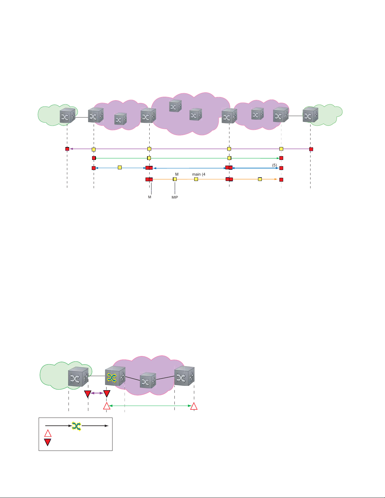
These roles define the relationships between all devices so that each device can monitor the layers under its
responsibility. Maintenance points drop all lower-level frames and forward all higher-level frames.
Figure 5-2. Maintenance Points
Customer Network
Service Provider Network
Customer Network
Ethernet Access
Operator Domain (5)
MEP
Maintenance End Points
A Maintenance End Point (MEP) is a logical entity that marks the end-point of a domain. There are two
types of MEPs defined in 802.1ag for an 802.1 bridge:
• Up-MEP: monitors the forwarding path internal to an bridge on the customer or provider edge; on
Dell Force10 systems the internal forwarding path is effectively the switch fabric and forwarding
engine.
• Down-MEP: monitors the forwarding path external another bridge.
Configure Up- MEPs on ingress ports, ports that send traffic towards the bridge relay. Configure
Down-MEPs on egress ports, ports that send traffic away from the bridge relay.
MPLS Core MPLS Access
Customer Domain (7)
Provider Domain (6)
Operator Domain (5)
MPLS Domain (4)
MIP
Operator Domain (5)
Figure 5-3. Up-MEP versus Down-MEP
Customer Network
towards relay
Up-MEP
Down-MEP
away from relay
Service Provider Ethernet Access
802.1ag | 75
Page 76

Implementation Information
• Since the S-Series has a single MAC address for all physical/LAG interfaces, only one MEP is allowed
per MA (per VLAN or per MD level).
Configure CFM
Configuring CFM is a five-step process:
1. Configure the ecfmacl CAM region using the
www.dell.com | support.dell.com
Sub-partitions.
2. Enable Ethernet CFM. See page 77.
3. Create a Maintenance Domain. See page 77.
4. Create a Maintenance Association. See page 78.
5. Create Maintenance Points. See page 78.
6. Use CFM tools:
a Continuity Check Messages on page 81
b Loopback Message and Response on page 82
c Linktrace Message and Response on page 82
Related Configuration Tasks
• Enable CFM SNMP Traps. on page 84
• Display Ethernet CFM Statistics on page 85
cam-acl command. See Configure Ingress Layer 2 ACL
76 | 802.1ag
Page 77

Enable Ethernet CFM
Task Command Syntax Command Mode
Spawn the CFM process. No CFM configuration is
allowed until the CFM process is spawned.
Disable Ethernet CFM without stopping the CFM
process.
ethernet cfm
disable ETHERNET CFM
CONFIGURATION
Create a Maintenance Domain
Connectivity Fault Management (CFM) divides a network into hierarchical maintenance domains, as
shown in Figure 5-1.
Step Task Command Syntax Command Mode
1 Create maintenance domain. domain name md-level number
Range: 0-7
2 Display maintenance domain information. show ethernet cfm domain [name |
brief]
Force10# show ethernet cfm domain
Domain Name: customer
Level: 7
Total Service: 1
Services
MA-Name VLAN CC-Int X-CHK Status
My_MA 200 10s enabled
Domain Name: praveen
Level: 6
Total Service: 1
Services
MA-Name VLAN CC-Int X-CHK Status
Your_MA 100 10s enabled
ETHERNET CFM
EXEC Privilege
802.1ag | 77
Page 78

Create a Maintenance Association
A Maintenance Association MA is a subdivision of an MD that contains all managed entities
corresponding to a single end-to-end service, typically a VLAN. An MA is associated with a VLAN ID.
Task Command Syntax Command Mode
Create maintenance association. service name vlan vlan-id ECFM DOMAIN
Create Maintenance Points
www.dell.com | support.dell.com
Domains are comprised of logical entities called Maintenance Points. A maintenance point is a interface
demarcation that confines CFM frames to a domain. There are two types of maintenance points:
• Maintenance End Points (MEPs): a logical entity that marks the end-point of a domain
• Maintenance Intermediate Points (MIPs): a logical entity configured at a port of a switch that
constitutes intermediate points of an Maintenance Entity (ME). An ME is a point-to-point relationship
between two MEPs within a single domain.
These roles define the relationships between all devices so that each device can monitor the layers under its
responsibility.
Create a Maintenance End Point
A Maintenance End Point (MEP) is a logical entity that marks the end-point of a domain. There are two
types of MEPs defined in 802.1ag for an 802.1 bridge:
• Up-MEP: monitors the forwarding path internal to an bridge on the customer or provider edge; on
Dell Force10 systems the internal forwarding path is effectively the switch fabric and forwarding
engine.
• Down-MEP: monitors the forwarding path external another bridge.
Configure Up- MEPs on ingress ports, ports that send traffic towards the bridge relay. Configure
Down-MEPs on egress ports, ports that send traffic away from the bridge relay.
Task Command Syntax Command Mode
Create an MEP. ethernet cfm mep {up-mep | down-mep} domain {name |
level
} ma-name name mepid mep-id
Range: 1-8191
Display configured MEPs and
MIPs.
show ethernet cfm maintenance-points local [mep | mip] EXEC Privilege
INTERFACE
78 | 802.1ag
Page 79

Task Command Syntax Command Mode
Force10#show ethernet cfm maintenance-points local mep
------------------------------------------------------------------------------MPID Domain Name Level Type Port CCM-Status
MA Name VLAN Dir MAC
-------------------------------------------------------------------------------
100 cfm0 7 MEP Gi 4/10 Enabled
test0 10 DOWN 00:01:e8:59:23:45
200 cfm1 6 MEP Gi 4/10 Enabled
test1 20 DOWN 00:01:e8:59:23:45
300 cfm2 5 MEP Gi 4/10 Enabled
test2 30 DOWN 00:01:e8:59:23:45
Create a Maintenance Intermediate Point
Maintenance Intermediate Point (MIP) is a logical entity configured at a port of a switch that constitutes
intermediate points of an Maintenance Entity (ME). An ME is a point-to-point relationship between two
MEPs within a single domain. An MIP is not associated with any MA or service instance, and it belongs to
the entire MD.
Task Command Syntax Command Mode
Create an MIP. ethernet cfm mip domain {name | level } ma-name name INTERFACE
Display configured MEPs and
MIPs.
Force10#show ethernet cfm maintenance-points local mip
------------------------------------------------------------------------------MPID Domain Name Level Type Port CCM-Status
MA Name VLAN Dir MAC
-------------------------------------------------------------------------------
0 service1 4 MIP Gi 0/5 Disabled
My_MA 3333 DOWN 00:01:e8:0b:c6:36
0 service1 4 MIP Gi 0/5 Disabled
Your_MA 3333 UP 00:01:e8:0b:c6:36
show ethernet cfm maintenance-points local [mep | mip] EXEC Privilege
MP Databases
CFM maintains two MP databases:
• MEP Database (MEP-DB): Every MEP must maintain a database of all other MEPs in the MA that
have announced their presence via CCM.
802.1ag | 79
Page 80

• MIP Database (MIP-DB): Every MIP must maintain a database of all other MEPs in the MA that
have announced their presence via CCM
Task Command Syntax Command Mode
Display the MEP Database.
Force10#show ethernet cfm maintenance-points remote detail
MAC Address: 00:01:e8:58:68:78
Domain Name: cfm0
MA Name: test0
Level: 7
www.dell.com | support.dell.com
VLAN: 10
MP ID: 900
Sender Chassis ID: Force10
MEP Interface status: Up
MEP Port status: Forwarding
Receive RDI: FALSE
MP Status: Active
Display the MIP Database.
MP Database Persistence
Task Command Syntax Command Mode
Set the amount of time that data
from a missing MEP is kept in
the Continuity Check Database.
show ethernet cfm maintenance-points remote detail [active
| domain {level | name} | expired | waiting]
show ethernet cfm mipdb
database hold-time minutes
Default: 100 minutes
Range: 100-65535 minutes
EXEC Privilege
EXEC Privilege
ECFM DOMAIN
80 | 802.1ag
Page 81

Continuity Check Messages
Continuity Check Messages (CCM) are periodic hellos used to:
• discover MEPs and MIPs within a maintenance domain
• detect loss of connectivity between MEPs
• detect misconfiguration, such as VLAN ID mismatch between MEPs
• to detect unauthorized MEPs in a maintenance domain
Continuity Check Messages (CCM) are multicast Ethernet frames sent at regular intervals from each MEP.
They have a destination address based on the MD level (01:80:C2:00:00:3X where X is the MD level of
the transmitting MEP from 0 to 7). All MEPs must listen to these multicast MAC addresses and process
these messages. MIPs may optionally processes the CCM messages originated by MEPs and construct a
MIP CCM database.
MEPs and MIPs filter CCMs from higher and lower domain levels as described in Table 5-1.
Table 5-1. Continuity Check Message Processing
Frames at Frames from UP-MEP Action Down-MEP Action MIP Action
Less than my level Bridge-relay side or Wire side Drop Drop Drop
My level Bridge-relay side Consume Drop Add to MIP-DB
Wire side Drop Consume
Greater than my level Bridge-relay side or Wire side Forward Forward Forward
and forward
All the remote MEPs in the maintenance domain are defined on each MEP. Each MEP then expects a
periodic CCM from the configured list of MEPs. A connectivity failure is then defined as:
1. Loss of 3 consecutive CCMs from any of the remote MEP, which indicates a network failure
2. Reception of a CCM with an incorrect CCM transmission interval, which indicates a configuration
error.
3. Reception of CCM with an incorrect MEP ID or MAID, which indicates a configuration or
cross-connect error. This could happen when different VLANs are cross-connected due to a
configuration error.
4. Reception of a CCM with an MD level lower than that of the receiving MEP, which indicates a
configuration or cross-connect error.
5. Reception of a CCM containing a port status/interface status TLV, which indicates a failed bridge or
aggregated port.
The Continuity Check protocol sends fault notifications (Syslogs, and SNMP traps if enabled) whenever
any of the above errors are encountered.
802.1ag | 81
Page 82

Enable CCM
Step Task Command Syntax Command Mode
1 Enable CCM.
2 Configure the transmit interval (mandatory).
The interval specified applies to all MEPs in
the domain.
Enable Cross-checking
www.dell.com | support.dell.com
Task Command Syntax Command Mode
Enable cross-checking.
Start the cross-check operation for an MEP. mep cross-check mep-id ETHERNET CFM
Configure the amount of time the system waits for a
remote MEP to come up before the cross-check operation
is started.
Loopback Message and Response
no ccm disable
Default: Disabled
ccm transmit-interval seconds
Default: 10 seconds
mep cross-check enable
Default: Disabled
mep cross-check start-delay
number
ECFM DOMAIN
ECFM DOMAIN
ETHERNET CFM
ETHERNET CFM
Loopback Message and Response (LBM, LBR), also called Layer 2 Ping, is an administrative echo
transmitted by MEPs to verify reachability to another MEP or MIP within the maintenance domain. LBM
and LBR are unicast frames.
Task Command Syntax Command Mode
Send a Loopback message. ping ethernet domain name ma-name ma-name remote
{mep-id | mac-addr mac-address} source {mep-id | port
interface}
EXEC Privilege
Linktrace Message and Response
Linktrace Message and Response (LTM, LTR), also called Layer 2 Traceroute, is an administratively sent
multicast frames transmitted by MEPs to track, hop-by-hop, the path to another MEP or MIP within the
maintenance domain. All MEPs and MIPs in the same domain respond to an LTM with a unicast LTR.
Intermediate MIPs forward the LTM toward the target MEP.
82 | 802.1ag
Page 83

Figure 5-4. Linktrace Message and Response
MPLS Core
MEP
MIP MIP
L
i
n
k
t
r
a
c
e
g
a
s
s
e
e
M
m
L
i
n
k
t
r
a
c
e
R
e
s
n
o
p
s
e
MIP
Link trace messages carry a unicast target address (the MAC address of an MIP or MEP) inside a multicast
frame. The destination group address is based on the MD level of the transmitting MEP
(01:80:C2:00:00:3[8 to F]). The MPs on the path to the target MAC address reply to the LTM with an LTR,
and relays the LTM towards the target MAC until the target MAC is reached or TTL equals 0.
Task Command Syntax Command Mode
Send a Linktrace message. Since the
L TM is a Multicast message sent to the
entire ME, there is no need to specify a
destination.
traceroute ethernet domain
EXEC Privilege
Link Trace Cache
After a Link Trace command is executed, the trace information can be cached so that you can view it later
without retracing.
Task Command Syntax Command Mode
Enable Link Trace caching.
Set the amount of time a trace result is cached. traceroute cache hold-time minutes
Set the size of the Link Trace Cache. traceroute cache size entries
Display the Link Trace Cache.
traceroute cache
Default: 100 minutes
Range: 10-65535 minutes
Default: 100
Range: 1 - 4095 entries
show ethernet cfm traceroute-cache
CONFIGURATION
ETHERNET CFM
ETHERNET CFM
EXEC Privilege
802.1ag | 83
Page 84

Task Command Syntax Command Mode
Force10#show ethernet cfm traceroute-cache
Traceroute to 00:01:e8:52:4a:f8 on Domain Customer2, Level 7, MA name Test2 with
VLAN 2
----------------------------------------------------------------------------- Hops Host IngressMAC Ingr Action Relay Action
Next Host Egress MAC Egress Action FWD Status
------------------------------------------------------------------------------
4 00:00:00:01:e8:53:4a:f8 00:01:e8:52:4a:f8 IngOK RlyHit
00:00:00:01:e8:52:4a:f8 Terminal MEP
www.dell.com | support.dell.com
Delete all Link Trace Cache entries.
Enable CFM SNMP Traps.
Task Command Syntax Command Mode
clear ethernet cfm traceroute-cache
EXEC Privilege
Enable SNMP trap messages for
Ethernet CFM.
A Trap is sent only when one of the five highest priority defects occur, as shown in Table 5-2.
Table 5-2. ECFM SNMP Traps
%ECFM-5-ECFM_XCON_ALARM: Cross connect fault detected by MEP 1 in Domain customer1
Cross-connect defect
Error-CCM defect
MAC Status defect
Remote CCM defect
RDI defect
at Level 7 VLAN 1000
%ECFM-5-ECFM_ERROR_ALARM: Error CCM Defect detected by MEP 1 in Domain customer1
at Level 7 VLAN 1000
%ECFM-5-ECFM_MAC_STATUS_ALARM: MAC Status Defect detected by MEP 1 in Domain
provider at Level 4 VLAN 3000
%ECFM-5-ECFM_REMOTE_ALARM: Remote CCM Defect detected by MEP 3 in Domain customer1
at Level 7 VLAN 1000
%ECFM-5-ECFM_RDI_ALARM: RDI Defect detected by MEP 3 in Domain customer1 at Level
7 VLAN 1000
snmp-server enable traps ecfm
CONFIGURATION
84 | 802.1ag
Page 85

Three values are giving within the trap messages: MD Index, MA Index, and MPID. You can reference
these values against the output of
local mep
.
Force10#show ethernet cfm maintenance-points local mep
------------------------------------------------------------------------------MPID Domain Name Level Type Port CCM-Status
MA Name VLAN Dir MAC
-------------------------------------------------------------------------------
100 cfm0 7 MEP Gi 4/10 Enabled
test0 10 DOWN 00:01:e8:59:23:45
Force10(conf-if-gi-0/6)#do show ethernet cfm domain
Domain Name: My_Name
MD Index: 1
Level: 0
Total Service: 1
Services
MA-Index MA-Name VLAN CC-Int X-CHK Status
1 test 0 1s enabled
Domain Name: Your_Name
MD Index: 2
Level: 2
Total Service: 1
Services
MA-Index MA-Name VLAN CC-Int X-CHK Status
1 test 100 1s enabled
show ethernet cfm domain and show ethernet cfm maintenance-points
Display Ethernet CFM Statistics
Task Command Syntax Command Mode
Display MEP CCM statistics. show ethernet cfm statistics [domain {name | level}
vlan-id
vlan-id mpid mpid
Force10# show ethernet cfm statistics
Domain Name: Customer
Domain Level: 7
MA Name: My_MA
MPID: 300
CCMs:
Transmitted: 1503 RcvdSeqErrors: 0
LTRs:
Unexpected Rcvd: 0
LBRs:
Received: 0 Rcvd Out Of Order: 0
Received Bad MSDU: 0
Transmitted: 0
EXEC Privilege
802.1ag | 85
Page 86

Task Command Syntax Command Mode
Display CFM statistics by port. show ethernet cfm port-statistics [interface] EXEC Privilege
Force10#show ethernet cfm port-statistics interface gigabitethernet 0/5
Port statistics for port: Gi 0/5
==================================
RX Statistics
=============
Total CFM Pkts 75394 CCM Pkts 75394
LBM Pkts 0 LTM Pkts 0
LBR Pkts 0 LTR Pkts 0
Bad CFM Pkts 0 CFM Pkts Discarded 0
www.dell.com | support.dell.com
CFM Pkts forwarded 102417
TX Statistics
=============
Total CFM Pkts 10303 CCM Pkts 0
LBM Pkts 0 LTM Pkts 3
LBR Pkts 0 LTR Pkts 0
86 | 802.1ag
Page 87
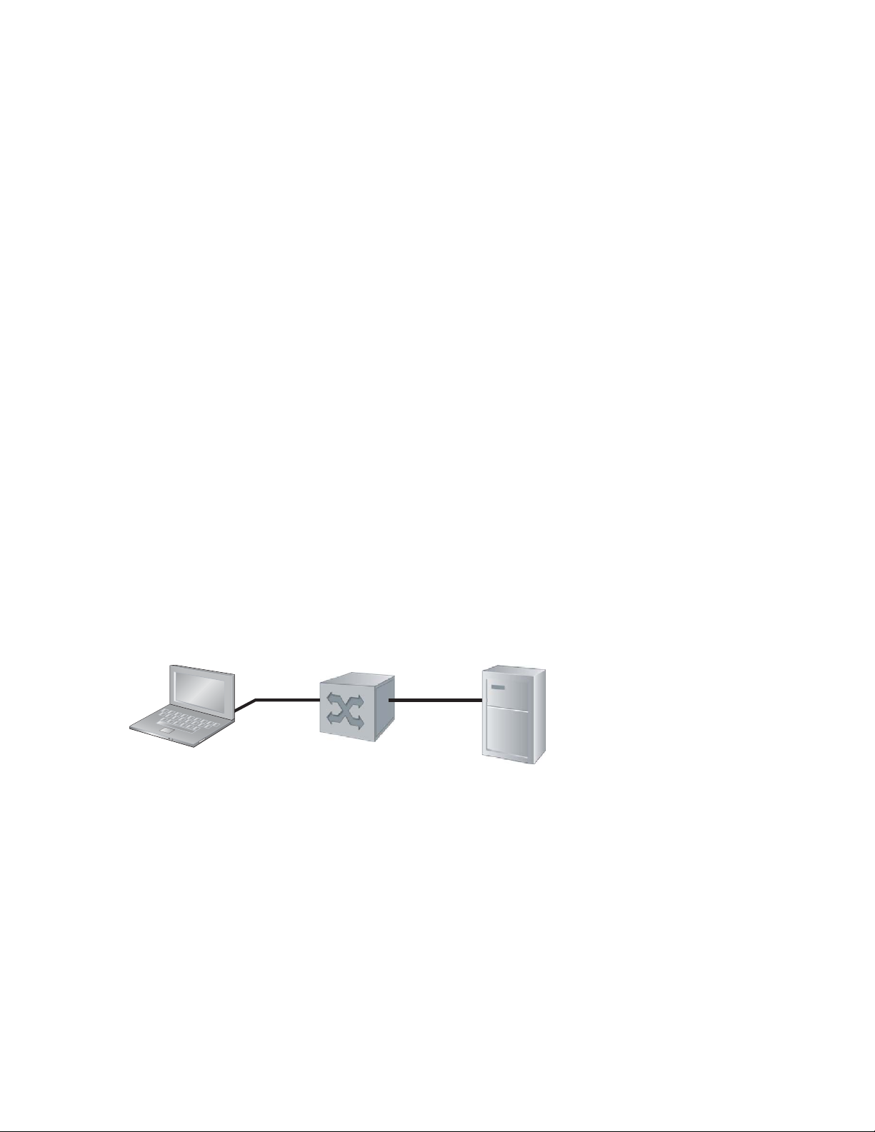
802.1X
er
fnC0033mp
802.1X is supported on platforms: c e s
Protocol Overview
802.1X is a method of port security . A device connected to a port that is enabled with 802.1X is disallowed
from sending or receiving packets on the network until its identity can be verified (through a username and
password, for example). This feature is named for its IEEE specification.
802.1X employs Extensible Authentication Protocol (EAP)* to transfer a device’s credentials to an
authentication server (typically RADIUS) via a mandatory intermediary network access device, in this
case, a Force10 switch. The network access device mediates all communication between the end-user
device and the authentication server so that the network remains secure. The network access device uses
EAP over Ethernet (EAPOL) to communicate with the end-user device and EAP over RADIUS to
communicate with the server.
6
End-user Device
EAP over LAN (EAPOL)
Figure 6-1 and Figure show how EAP frames are encapsulated in Ethernet and Radius frames.
Note: FTOS supports 802.1X with EAP-MD5, EAP-OTP, EAP-TLS, EAP-TTLS, PEAPv0, PEAPv1, and
MS-CHAPv2 with PEAP.
Force10 switch
RADIUS Serv
EAP over RADIUS
802.1X | 87
Page 88
Figure 6-1. EAPOL Frame Format
Preamble
Start Frame
Delimiter
Range: 0-4
Range: 0-4
Type: 0: EAP Packet
Type: 0: EAP Packet
1: EAPOL Start
1: EAPOL Start
2: EAPOL Logoff
2: EAPOL Logoff
3: EAPOL Key
3: EAPOL Key
4: EAPOL Encapsulated-ASF-Alert
4: EAPOL Encapsulated-ASF-Alert
Destination MAC
(1:80:c2:00:00:03)
Source MAC
(Auth Port MAC)
www.dell.com | support.dell.com
The authentication process involves three devices:
• The device attempting to access the network is the supplicant. The supplicant is not allowed to
communicate on the network until the port is authorized by the authenticator. It can only communicate
with the authenticator in response to 802.1X requests.
• The device with which the supplicant communicates is the authenticator. The authenicator is the gate
keeper of the network. It translates and forwards requests and responses between the authentication
server and the supplicant. The authenticator also changes the status of the port based on the results of
the authentication process. The Force10 switch is the authenticator.
• The authentication-server selects the authentication method, verifies the information provided by the
supplicant, and grants it network access privileges.
Protocol Version
(1)
Range: 1-4
Codes: 1: Request
2: Response
3: Success
4: Failure
Ethernet Type
(0x888e)
Packet Type
Range: 1-255
Codes: 1: Identity
2: Notification
3: NAK
4: MD-5 Challenge
5: One-Time Challenge
6: Generic Token Card
Code
(0-4)
Length
ID
(Seq Number)
EAPOL Frame
Length
EAP-Method
Code
(0-255)
EAP Frame
Length
Padding
FCS
EAP-Method Frame
EAP-Method Data
(Supplicant Requested Credentials)
Ports can be in one of two states:
• Ports are in an unauthorized state by default. In this state, non-802.1X traffic cannot be forwarded in
• The authenticator changes the port state to authorized if the server can authenticate the supplicant. In
The Port-authentication Process
The authentication process begins when the authenticator senses that a link status has changed from down
to up:
1. When the authenticator senses a link state change, it requests that the supplicant identify itself using an
2. The supplicant responds with its identity in an EAP Response Identity frame.
88 | 802.1X
or out of the port.
this state, network traffic can be forwarded normally.
Note: The Force10 switches place 802.1X-enabled ports in the unauthorized state by default.
EAP Identity Request Frame.
Page 89

3. The authenticator decapsulates the EAP Response from the EAPOL frame, encapsulates it in a
on
EAP {Sucess | Failure}
RADIUS Access-Request frame, and forwards the frame to the authentication server.
4. The authentication server replies with an Access-Challenge. The Access-Challenge is request that the
supplicant prove that it is who it claims to be, using a specified method (an EAP-Method). The
challenge is translated and forwarded to the supplicant by the authenticator.
5. The supplicant can negotiate the authentication method, but if it is acceptable, the supplicant provides
the requested challenge information in an EAP Response, which is translated and forwarded to the
authentication server as another Access-Request.
6. If the identity information provided by the supplicant is valid, the authentication server sends an
Access-Accept frame in which network privileges are specified. The authenticator changes the port
state to authorized, and forwards an EAP Success frame. If the identity information is invalid, the
server sends and Access-Reject frame. The port state remains unauthorized, and the authenticator
forwards EAP Failure frame.
Figure 6-2. 802.1X Authentication Process
Supplicant
Authenticator
Authenticati
Server
EAP over LAN (EAPOL)
Request Identity
Response Identity
EAP Request
EAP Reponse
EAP over RADIUS
Access Request
Access Challenge
Access Request
Access {Accept | Reject}
EAP over RADIUS
802.1X uses RADIUS to shuttle EAP packets between the authenticator and the authentication server, as
defined in RFC 3579. EAP messages are encapsulated in RADIUS packets as a type of attribute in Type,
Length, Value (TLV) format. The Type value for EAP messages is 79.
802.1X | 89
Page 90

Figure 6-3. RADIUS Frame Format
R
C
p
Code
ange: 1-4
odes: 1: Access-Request
2: Access-Accept
3: Access-Reject
11: Access-Challenge
www.dell.com | support.dell.com
RADIUS Attributes for 802.1 Support
Identifier
Length
Force10 systems includes the following RADIUS attributes in all 802.1X-triggered Access-Request
messages:
• Attribute 5—NAS-Port: the physical port number by which the authenticator is connected to the
supplicant.
• Attribute 31—Calling-station-id: relays the supplicant MAC address to the authentication server.
• Attribute 41—NAS-Port-Type: NAS-port physical port type. 5 indicates Ethernet.
• Attribute 81—Tunnel-Private-Group-ID: associate a tunneled session with a particular group of
users.
Message-Authenticator
Attribute
Type
(79)
Length
EAP-Message Attribute
EAP-Method Data
(Supplicant Requested Credentials)
fnC0034m
90 | 802.1X
Page 91

Configuring 802.1X
Configuring 802.1X on a port is a two-step process:
1. Enable 802.1X globally. See page 91.
2. Enable 802.1X on an interface. See page 91.
Related Configuration Tasks
• Configuring Request Identity Re-transmissions on page 93
• Configuring Port-control on page 95
• Re-authenticating a Port on page 96
• Configuring Timeouts on page 97
• Configuring a Guest VLAN on page 100
• Configuring an Authentication-fail VLAN on page 100
Important Points to Remember
• FTOS supports 802.1X with EAP-MD5, EAP-OTP, EAP-TLS, EAP-TTLS, PEAPv0, PEAPv1, and
MS-CHAPv2 with PEAP.
• E-Series and C-Series support only RADIUS as the authentication server.
• 802.1X is not supported on port-channels or port-channel members.
Enabling 802.1X
802.1X must be enabled globally and at interface level.
802.1X | 91
Page 92

Figure 6-4. Enabling 802.1X
on
F
F
F
F
!
i
!
i
Supplicant
Authenticator
Authenticati
Server
orce10(conf)#dot1x authentication
orce10(conf)#interface range gigabitethernet 2/1 - 2
orce10(conf-if-range-gi-2/1-2)#dot1x authentication
orce10(conf-if-range-gi-2/1-2)#show config
nterface GigabitEthernet 2/1
ip address 2.2.2.2/24
dot1x authentication
www.dell.com | support.dell.com
no shutdown
nterface GigabitEthernet 2/2
ip address 1.0.0.1/24
dot1x authentication
no shutdown
To enable 802.1X:
Step Task Command Syntax Command Mode
1 Enable 802.1X globally.
2 Enter INTERFACE mode on an interface or a range of
interfaces.
3 Enable 802.1X on an interface or a range of interfaces. dot1x authentication INTERFACE
2/1
2/2
dot1x authentication
CONFIGURATION
interface [range] INTERFACE
92 | 802.1X
Verify that 802.1X is enabled globally and at interface level using the command
dot1x
from EXEC Privilege mode, as shown in Figure 6-5.
show running-config | find
Figure 6-5. Verifying 802.1X Global Configuration
Force10#show running-config | find dot1x
dot1x authentication
802.1X Enabled
!
[output omitted]
!
interface GigabitEthernet 2/1
ip address 2.2.2.2/24
dot1x authentication
802.1X Enabled on
no shutdown
!
interface GigabitEthernet 2/2
ip address 1.0.0.1/24
dot1x authentication
no shutdown
--More--
View 802.1X configuration information for an interface using the command show dot1x interface, as
shown in Figure 6-6.
Page 93

Figure 6-6. Verifying 802.1X Interface Configuration
Force10#show dot1x interface gigabitethernet 2/1
802.1x information on Gi 2/1:
----------------------------Dot1x Status: Enable
Port Control: AUTO
Port Auth Status: UNAUTHORIZED
Re-Authentication: Disable
Untagged VLAN id: None
Tx Period: 30 seconds
Quiet Period: 60 seconds
ReAuth Max: 2
Supplicant Timeout: 30 seconds
Server Timeout: 30 seconds
Re-Auth Interval: 3600 seconds
Max-EAP-Req: 2
Auth Type: SINGLE_HOST
Auth PAE State: Initialize
Backend State: Initialize
802.1X Enabled on
All ports unauthorized by
Configuring Request Identity Re-transmissions
If the authenticator sends a Request Identity frame, but the supplicant does not respond, the authenticator
waits 30 seconds and then re-transmits the frame. The amount of time that the authenticator waits before
re-transmitting and the maximum number of times that the authenticator re-transmits are configurable.
Note: There are several reasons why the supplicant might fail to respond; the supplicant might have been
booting when the request arrived, or there might be a physical layer problem.
To configure the amount of time that the authenticator waits before re-transmitting an EAP Request
Identity frame:
Step Task Command Syntax Command Mode
1 Configure the amount of time that the authenticator
waits before re-transmitting an EAP Request Identity
frame.
dot1x tx-period number
Range: 1-31536000 (1 year)
Default: 30
INTERFACE
To configure a maximum number of Request Identity re-transmissions:
Step Task Command Syntax Command Mode
1 Configure a maximum number of times that a Request
Identity frame can be re-transmitted by the
authenticator.
dot1x max-eap-req number
Range: 1-10
Default: 2
INTERFACE
Figure 6-7 shows configuration information for a port for which the authenticator re-transmits an EAP
Request Identity frame after 90 seconds and re-transmits a maximum of 10 times.
802.1X | 93
Page 94
Configuring a Quiet Period after a Failed Authentication
If the supplicant fails the authentication process, the authenticator sends another Request Identity frame
after 30 seconds by default, but this period can be configured.
Note: The quiet period (dot1x quiet-period) is an transmit interval for after a failed authentication where as
the Request Identity Re-transmit interval (dot1x tx-period) is for an unresponsive supplicant.
To configure the quiet period after a failed authentication:
Step Task Command Syntax Command Mode
www.dell.com | support.dell.com
1 Configure the amount of time that the authenticator
waits to re-transmit a Request Identity frame after a
failed authentication.
Figure 6-7 shows configuration information for a port for which the authenticator re-transmits an EAP
Request Identity frame:
• after 90 seconds and a maximum of 10 times for an unresponsive supplicant
• Re-transmits an EAP Request Identity frame
Figure 6-7. Configuring a Request Identity Re-transmissions
Force10(conf-if-range-gi-2/1)#dot1x tx-period 90
Force10(conf-if-range-gi-2/1)#dot1x max-eap-req 10
Force10(conf-if-range-gi-2/1)#dot1x quiet-period 120
Force10#show dot1x interface gigabitethernet 2/1
802.1x information on Gi 2/1:
----------------------------Dot1x Status: Enable
Port Control: AUTO
Port Auth Status: UNAUTHORIZED
Re-Authentication: Disable
Untagged VLAN id: None
Tx Period: 90 seconds
Quiet Period: 120 seconds
ReAuth Max: 2
Supplicant Timeout: 30 seconds
Server Timeout: 30 seconds
Re-Auth Interval: 3600 seconds
Max-EAP-Req: 10
Auth Type: SINGLE_HOST
dot1x quiet-period seconds
Range: 1-65535
Default: 60
New Re-transmit
New Quiet Period
New Maximum
INTERFACE
94 | 802.1X
Auth PAE State: Initialize
Backend State: Initialize
Page 95

Forcibly Authorizing or Unauthorizing a Port
IEEE 802.1X requires that a port can be manually placed into any of three states:
• ForceAuthorized is an authorized state. A device connected to this port in this state is never subjected
to the authentication process, but is allowed to communicate on the network. Placing the port in this
state is same as disabling 802.1X on the port.
• ForceUnauthorized an unauthorized state. A device connected to a port in this state is never subjected
to the authentication process and is not allowed to communicate on the network. Placing the port in
this state is the same as shutting down the port. Any attempt by the supplicant to initiate authentication
is ignored.
• Auto is an unauthorized state by default. A device connected to this port is this state is subjected to the
authentication process. If the process is successful, the port is authorized and the connected device can
communicate on the network. All ports are placed in the auto state by default.
To place a port in one of these three states:
Step Task Command Syntax Command Mode
1 Place a port in the ForceAuthorized,
ForceUnauthorized, or Auto state.
dot1x port-control {force-authorized |
force-unauthorized | auto}
Default: auto
Figure 6-8 shows configuration information for a port that has been force-authorized.
Figure 6-8. Configuring Port-control
Force10(conf-if-gi-2/1)#dot1x port-control force-authorized
Force10(conf-if-gi-2/1)#do show dot1x interface gigabitethernet 2/1
802.1x information on Gi 2/1:
----------------------------Dot1x Status: Enable
Port Control: FORCE_AUTHORIZED
Port Auth Status: UNAUTHORIZED
Re-Authentication: Disable
Untagged VLAN id: None
Tx Period: 90 seconds
Quiet Period: 120 seconds
ReAuth Max: 2
Supplicant Timeout: 30 seconds
Server Timeout: 30 seconds
Re-Auth Interval: 3600 seconds
Max-EAP-Req: 10
Auth Type: SINGLE_HOST
Auth PAE State: Initialize
Backend State: Initialize
Auth PAE State: Initialize
Backend State: Initialize
New Port-control State
INTERFACE
802.1X | 95
Page 96

Re-authenticating a Port
Periodic Re-authentication
After the supplicant has been authenticated, and the port has been authorized, the authenticator can be
configured to re-authenticates the supplicant periodically. If re-authentication is enabled, the supplicant is
required to re-authenticate every 3600 seconds, but this interval can be configured. A maximum number of
re-authentications can be configured as well.
To configure a re-authentication or a re-authentication period:
www.dell.com | support.dell.com
Step Task Command Syntax Command Mode
1 Configure the authenticator to
periodically re-authenticate the
supplicant.
To configure a maximum number of re-authentications:
Step Task Command Syntax Command Mode
1 Configure the maximum number of
times that the supplicant can be
reauthenticated.
Figure 6-9. Configuring a Reauthentiction Period
Force10(conf-if-gi-2/1)#dot1x reauthentication interval 7200
Force10(conf-if-gi-2/1)#dot1x reauth-max 10
Force10(conf-if-gi-2/1)#do show dot1x interface gigabitethernet 2/1
802.1x information on Gi 2/1:
----------------------------Dot1x Status: Enable
Port Control: FORCE_AUTHORIZED
Port Auth Status: UNAUTHORIZED
Re-Authentication: Enable
Untagged VLAN id: None
Tx Period: 90 seconds
Quiet Period: 120 seconds
ReAuth Max: 10
Supplicant Timeout: 30 seconds
Server Timeout: 30 seconds
Re-Auth Interval: 7200 seconds
Max-EAP-Req: 10
Auth Type: SINGLE_HOST
dot1x reauthentication [interval] seconds
Range: 1-65535
Default: 60
dot1x reauth-max number
Range: 1-10
Default: 2
Re-authentication
New Maximum
New Re-authentication
INTERFACE
INTERFACE
96 | 802.1X
Auth PAE State: Initialize
Backend State: Initialize
Auth PAE State: Initialize
Page 97

Configuring Timeouts
If the supplicant or the authentication server is unresponsive, the authenticator terminates the
authentication process after 30 seconds by default. This amount of time that the authenticator waits for a
response can be configured.
To terminate the authentication process due to an unresponsive supplicant:
Step Task Command Syntax Command Mode
1 T erminate the authentication process due to an
unresponsive supplicant.
dot1x supplicant-timeout seconds
Range: 1-300
INTERFACE
Default: 30
To terminate the authentication process due to an unresponsive authentication server:
Step Task Command Syntax Command Mode
1 T erminate the authentication process due to an
unresponsive authentication server.
dot1x server-timeout seconds
Range: 1-300
INTERFACE
Default: 30
Figure 6-10 shows configuration information for a port for which the authenticator terminates the
authentication process for an unresponsive supplicant or server after 15 seconds.
Figure 6-10. Configuring a Timeout
Force10(conf-if-gi-2/1)#dot1x port-control force-authorized
Force10(conf-if-gi-2/1)#do show dot1x interface gigabitethernet 2/1
802.1x information on Gi 2/1:
----------------------------Dot1x Status: Enable
Port Control: FORCE_AUTHORIZED
Port Auth Status: UNAUTHORIZED
Re-Authentication: Disable
Untagged VLAN id: None
Guest VLAN: Disable
Guest VLAN id: NONE
Auth-Fail VLAN: Disable
Auth-Fail VLAN id: NONE
Auth-Fail Max-Attempts: NONE
Tx Period: 90 seconds
Quiet Period: 120 seconds
ReAuth Max: 10
Supplicant Timeout: 15 seconds
Server Timeout: 15 seconds
Re-Auth Interval: 7200 seconds
Max-EAP-Req: 10
Auth Type: SINGLE_HOST
New Supplicant and Server
Auth PAE State: Initialize
Backend State: Initialize
802.1X | 97
Page 98

Dynamic VLAN Assignment with Port Authentication
FTOS supports dynamic VLAN assignment when using 802.1X. The basis for VLAN assignment is
RADIUS attribute 81, Tunnel-Private-Group-ID. Dynamic VLAN assignment uses the standard dot1x
procedure: 1) the host sends a dot1x packet to the Force10 system, 2) the system forwards a RADIUS
REQEST packet containing the host MAC address and ingress port number, and 3) the RADIUS server
authenticates the request and returns a RADIUS ACCEPT message with the VLAN assignment using
Tunnel-Private-Group-ID.
Step Task
1 Configure 8021.x globally and at interface level (see Enabling 802.1X on page 91) along with relevant RADIUS
www.dell.com | support.dell.com
server configurations (Figure 6-11)
2 Make the interface a switchport so that it can be assigned to a VLAN.
3 Create the VLAN to which the interface will be assigned.
4 Connect the supplicant to the port configured for 802.1X.
5 Verify that the port has been authorized and placed in the desired VLAN (Figure 6-11, red text).
In Figure 6-11 shows the configuration on the Force10 system before connecting the end-user device in
black and blue text, and after connecting the device in red text. The blue text corresponds to the preceding
numbered steps on dynamic VLAN assignment with 802.1X.
98 | 802.1X
Page 99

Figure 6-11. Dynamic VLAN Assignment with 802.1X
F
8
D
P
P
R
U
T
Q
R
S
S
R
M
A
A
B
1
Force10(conf-if-gi-1/10)#show config
interface GigabitEthernet 1/10
no ip address
switchport
dot1x authentication
no shutdow
2
1
radius-server host 10.11.197.169 auth-port 1645
key 7 387a7f2df5969da4
End-user Device
orce10#show dot1x interface gigabitethernet 1/10
02.1x information on Gi 1/10:
---------------------------ot1x Status: Enable
ort Control: AUTO
ort Auth Status: AUTHORIZED
e-Authentication: Disable
ntagged VLAN id: 400
x Period: 30 seconds
uiet Period: 60 seconds
eAuth Max: 2
upplicant Timeout: 30 seconds
erver Timeout: 30 seconds
e-Auth Interval: 3600 seconds
ax-EAP-Req: 2
uth Type: SINGLE_HOST
uth PAE State: Authenticated
ackend State: Idle
Force10 switch
1/10
4
Force10(conf-if-vl-400)# show config
interface Vlan 400
no ip address
shutdown
Force10#show vlan
Codes: * - Default VLAN, G - GVRP VLANs
Q: U - Untagged, T - Tagged
x - Dot1x untagged, X - Dot1x tagged
G - GVRP tagged
NUM Status Description Q Ports
* 1 Inactive U Gi 1/10
400 Inactive
Force10#show vlan
Codes: * - Default VLAN, G - GVRP VLANs
Q: U - Untagged, T - Tagged
x - Dot1x untagged, X - Dot1x tagged
G - GVRP tagged
3
RADIUS Server
fnC0065mp
NUM Status Description Q Ports
* 1 Inactive
400 Active U Gi 1/10
Guest and Authentication-fail VLANs
Typically, the authenticator (Force10 system) denies the supplicant access to the network until the
supplicant is authenticated. If the supplicant is authenticated, the authenticator enables the port and places
it in either the VLAN for which the port is configured, or the VLAN that the authentication server indicates
in the authentication data.
Note: Ports cannot be dynamically assigned to the default VLAN.
802.1X | 99
Page 100

If the supplicant fails authentication, the authenticator typically does not enable the port. In some cases this
behavior is not appropriate. External users of an enterprise network, for example, might not be able to be
authenticated, but still need access to the network. Also, some dumb-terminals such as network printers do
not have 802.1X capability and therefore cannot authenticate themselves. To be able to connect such
devices, they must be allowed access the network without compromising network security.
The Guest VLAN 802.1X extension addresses this limitation with regard to non-802.1X capable devices,
and the Authentication-fail VLAN 802.1X extension addresses this limitation with regard to external users.
• If the supplicant fails authentication a specified number of times, the authenticator places the port in
the Authentication-fail VLAN.
• If a port is already forwarding on the Guest VLAN when 802.1X is enabled, then the port is moved out
of the Guest VLAN, and the authentication process begins.
www.dell.com | support.dell.com
Configuring a Guest VLAN
If the supplicant does not respond within a determined amount of time ([reauth-max + 1] * tx-period, see
Configuring Timeouts on page 97) the system assumes that the host does not have 802.1X capability, and
the port is placed in the Guest VLAN.
Configure a port to be placed in the Guest VLAN after failing to respond within the timeout period using
the command
dot1x guest-vlan from INTERFACE mode, as shown in Figure 6-12.
Figure 6-12. Configuring a Guest VLAN
Force10(conf-if-gi-1/2)#dot1x guest-vlan 200
Force10(conf-if-gi-1/2)#show config
!
interface GigabitEthernet 1/2
switchport
dot1x guest-vlan 200
no shutdown
Force10(conf-if-gi-1/2)#
View your configuration using the command show config from INTERFACE mode, as shown in
Figure 6-12, or using the command
show dot1x interface command from EXEC Privilege mode as shown
in Figure 6-14.
Configuring an Authentication-fail VLAN
If the supplicant fails authentication, the authenticator re-attempts to authenticate after a specified amount
of time (30 seconds by default, see Configuring a Quiet Period after a Failed Authentication on page 94).
You can configure the maximum number of times the authenticator re-attempts authentication after a
failure (3 by default), after which the port is placed in the Authentication-fail VLAN.
Configure a port to be placed in the VLAN after failing the authentication process as specified number of
times using the command
Configure the maximum number of authentication attempts by the authenticator using the keyword
max-attempts with this command.
dot1x auth-fail-vlan from INTERFACE mode, as shown in Figure 6-13.
100 | 802.1X
 Loading...