

Page 1

Dell Configuration Guide for the S4810
System
9.5(0.0)
Page 2

Notes, Cautions, and Warnings
NOTE: A NOTE indicates important information that helps you make better use of your computer.
CAUTION: A CAUTION indicates either potential damage to hardware or loss of data and tells you
how to avoid the problem.
WARNING: A WARNING indicates a potential for property damage, personal injury, or death.
Copyright © 2014 Dell Inc. All rights reserved. This product is protected by U.S. and international copyright and
intellectual property laws. Dell™ and the Dell logo are trademarks of Dell Inc. in the United States and/or other
jurisdictions. All other marks and names mentioned herein may be trademarks of their respective companies.
2014 - 06
Rev. A00
Page 3

Contents
1 About this Guide......................................................................................................35
Audience..............................................................................................................................................35
Conventions........................................................................................................................................ 35
Related Documents.............................................................................................................................35
2 Configuration Fundamentals.............................................................................. 36
Accessing the Command Line............................................................................................................36
CLI Modes............................................................................................................................................36
Navigating CLI Modes................................................................................................................... 37
The do Command...............................................................................................................................40
Undoing Commands...........................................................................................................................41
Obtaining Help.................................................................................................................................... 42
Entering and Editing Commands....................................................................................................... 42
Command History...............................................................................................................................43
Filtering show Command Outputs.....................................................................................................43
Multiple Users in Configuration Mode............................................................................................... 45
3 Getting Started........................................................................................................46
Console Access...................................................................................................................................46
Serial Console................................................................................................................................46
Accessing the CLI Interface and Running Scripts Using SSH............................................................ 47
S4810 ............................................................................................................................................ 47
Entering CLI commands Using an SSH Connection................................................................... 48
Executing Local CLI Scripts Using an SSH Connection...............................................................48
Default Configuration......................................................................................................................... 49
Configuring a Host Name...................................................................................................................49
Accessing the System Remotely........................................................................................................ 49
Accessing the S4810 and Remotely.............................................................................................49
Configure the Management Port IP Address............................................................................... 50
Configure a Management Route..................................................................................................50
Configuring a Username and Password.......................................................................................50
Configuring the Enable Password.......................................................................................................51
Configuration File Management......................................................................................................... 51
Copy Files to and from the System...............................................................................................51
Save the Running-Configuration..................................................................................................52
Configure the Overload Bit for a Startup Scenario...................................................................... 53
Viewing Files.................................................................................................................................. 53
Compressing Configuration Files................................................................................................. 54
Page 4

Managing the File System................................................................................................................... 57
Enabling Software Features on Devices Using a Command Option................................................ 58
View Command History......................................................................................................................59
Upgrading Dell Networking OS.......................................................................................................... 59
Using Hashes to Validate Software Images........................................................................................59
Using HTTP for File Transfers.............................................................................................................60
4 Management............................................................................................................62
Configuring Privilege Levels............................................................................................................... 62
Creating a Custom Privilege Level................................................................................................62
Removing a Command from EXEC Mode................................................................................... 62
Moving a Command from EXEC Privilege Mode to EXEC Mode................................................ 62
Allowing Access to CONFIGURATION Mode Commands.......................................................... 63
Allowing Access to the Following Modes.................................................................................... 63
Applying a Privilege Level to a Username.................................................................................... 65
Applying a Privilege Level to a Terminal Line...............................................................................65
Configuring Logging...........................................................................................................................65
Audit and Security Logs................................................................................................................ 66
Configuring Logging Format .......................................................................................................67
Display the Logging Buffer and the Logging Configuration....................................................... 68
Setting Up a Secure Connection to a Syslog Server....................................................................69
Sending System Messages to a Syslog Server..............................................................................70
Log Messages in the Internal Buffer...................................................................................................70
Configuration Task List for System Log Management.................................................................70
Disabling System Logging...................................................................................................................70
Sending System Messages to a Syslog Server.................................................................................... 71
Configuring a UNIX System as a Syslog Server.............................................................................71
Changing System Logging Settings.................................................................................................... 71
Display the Logging Buffer and the Logging Configuration..............................................................72
Configuring a UNIX Logging Facility Level.........................................................................................73
Synchronizing Log Messages..............................................................................................................74
Enabling Timestamp on Syslog Messages..........................................................................................75
File Transfer Services...........................................................................................................................75
Configuration Task List for File Transfer Services........................................................................ 75
Enabling the FTP Server................................................................................................................ 76
Configuring FTP Server Parameters..............................................................................................76
Configuring FTP Client Parameters.............................................................................................. 76
Terminal Lines......................................................................................................................................77
Denying and Permitting Access to a Terminal Line..................................................................... 77
Configuring Login Authentication for Terminal Lines................................................................. 78
Setting Time Out of EXEC Privilege Mode......................................................................................... 79
Using Telnet to get to Another Network Device............................................................................... 79
Page 5

Lock CONFIGURATION Mode........................................................................................................... 80
Viewing the Configuration Lock Status........................................................................................80
Recovering from a Forgotten Password on the S4810 System.........................................................81
Recovering from a Forgotten Enable Password on the S4810 .................................................. 82
Recovering from a Failed Start on the S4810 System....................................................................... 83
Restoring the Factory Default Settings.............................................................................................. 84
S4810MXL Switch..........................................................................................................................84
Important Points to Remember....................................................................................................84
5 802.1ag......................................................................................................................85
Ethernet CFM...................................................................................................................................... 85
Maintenance Domains........................................................................................................................86
Maintenance Points............................................................................................................................ 86
Maintenance End Points..................................................................................................................... 87
Implementation Information..............................................................................................................88
Configuring the CFM.......................................................................................................................... 88
Related Configuration Tasks.........................................................................................................88
Enabling Ethernet CFM.......................................................................................................................88
Creating a Maintenance Domain....................................................................................................... 89
Creating a Maintenance Association..................................................................................................89
Create Maintenance Points................................................................................................................ 89
Creating a Maintenance End Point...............................................................................................90
Creating a Maintenance Intermediate Point................................................................................90
Displaying the MP Databases........................................................................................................ 91
Continuity Check Messages............................................................................................................... 92
Enabling CCM................................................................................................................................93
Enabling Cross-Checking............................................................................................................. 93
Sending Loopback Messages and Responses....................................................................................93
Sending Linktrace Messages and Responses.....................................................................................94
Caching Link Trace....................................................................................................................... 94
Enabling CFM SNMP Traps................................................................................................................. 95
Displaying Ethernet CFM Statistics..................................................................................................... 97
6 802.1X........................................................................................................................98
The Port-Authentication Process.......................................................................................................99
EAP over RADIUS......................................................................................................................... 101
Configuring 802.1X............................................................................................................................101
Related Configuration Tasks....................................................................................................... 101
Important Points to Remember........................................................................................................102
Enabling 802.1X.................................................................................................................................103
Configuring Request Identity Re-Transmissions.............................................................................104
Configuring a Quiet Period after a Failed Authentication......................................................... 105
Page 6

Forcibly Authorizing or Unauthorizing a Port..................................................................................106
Re-Authenticating a Port.................................................................................................................. 107
Configuring Timeouts.......................................................................................................................108
Configuring Dynamic VLAN Assignment with Port Authentication................................................109
Guest and Authentication-Fail VLANs.............................................................................................. 110
Configuring a Guest VLAN...........................................................................................................111
Configuring an Authentication-Fail VLAN...................................................................................111
7 Access Control List (ACL) VLAN Groups and Content Addressable
Memory (CAM)...........................................................................................................113
Optimizing CAM Utilization During the Attachment of ACLs to VLANs..........................................113
Guidelines for Configuring ACL VLAN groups................................................................................. 114
Configuring ACL VLAN Groups and Configuring FP Blocks for VLAN Parameters.........................115
Configuring ACL VLAN Groups................................................................................................... 115
Configuring FP Blocks for VLAN Parameters..............................................................................116
Viewing CAM Usage...........................................................................................................................117
Allocating FP Blocks for VLAN Processes.........................................................................................118
8 Access Control Lists (ACLs)................................................................................120
IP Access Control Lists (ACLs)...........................................................................................................121
CAM Usage...................................................................................................................................121
Implementing ACLs on Dell Networking OS..............................................................................123
Important Points to Remember........................................................................................................124
Configuration Task List for Route Maps..................................................................................... 124
Configuring Match Routes.......................................................................................................... 127
Configuring Set Conditions........................................................................................................ 128
Configure a Route Map for Route Redistribution...................................................................... 129
Configure a Route Map for Route Tagging................................................................................130
Continue Clause..........................................................................................................................130
IP Fragment Handling........................................................................................................................131
IP Fragments ACL Examples........................................................................................................131
Layer 4 ACL Rules Examples....................................................................................................... 132
Configure a Standard IP ACL............................................................................................................ 133
Configuring a Standard IP ACL Filter.......................................................................................... 134
Configure an Extended IP ACL......................................................................................................... 135
Configuring Filters with a Sequence Number............................................................................ 135
Configuring Filters Without a Sequence Number......................................................................136
Configure Layer 2 and Layer 3 ACLs.................................................................................................137
Assign an IP ACL to an Interface.......................................................................................................138
Applying an IP ACL............................................................................................................................138
Counting ACL Hits.......................................................................................................................139
Configure Ingress ACLs.....................................................................................................................139
Page 7

Configure Egress ACLs..................................................................................................................... 140
Applying Egress Layer 3 ACLs (Control-Plane)...........................................................................141
IP Prefix Lists...................................................................................................................................... 141
Implementation Information...................................................................................................... 142
Configuration Task List for Prefix Lists....................................................................................... 142
ACL Resequencing............................................................................................................................146
Resequencing an ACL or Prefix List............................................................................................147
Route Maps........................................................................................................................................148
Implementation Information...................................................................................................... 148
Logging of ACL Processes................................................................................................................149
Guidelines for Configuring ACL Logging................................................................................... 150
Configuring ACL Logging........................................................................................................... 150
Flow-Based Monitoring Support for ACLs........................................................................................151
Behavior of Flow-Based Monitoring........................................................................................... 151
Enabling Flow-Based Monitoring............................................................................................... 153
9 Bidirectional Forwarding Detection (BFD).....................................................155
How BFD Works................................................................................................................................ 155
BFD Packet Format......................................................................................................................156
BFD Sessions................................................................................................................................158
BFD Three-Way Handshake........................................................................................................158
Session State Changes................................................................................................................ 159
Important Points to Remember....................................................................................................... 160
Configure BFD...................................................................................................................................160
Configure BFD for Physical Ports................................................................................................161
Configure BFD for Static Routes.................................................................................................164
Configure BFD for OSPF............................................................................................................. 166
Configure BFD for OSPFv3......................................................................................................... 169
Configure BFD for IS-IS...............................................................................................................170
Configure BFD for BGP............................................................................................................... 173
Configure BFD for VRRP............................................................................................................. 180
Configuring Protocol Liveness................................................................................................... 183
Troubleshooting BFD.................................................................................................................. 183
10 Border Gateway Protocol IPv4 (BGPv4)....................................................... 185
Autonomous Systems (AS)................................................................................................................185
Sessions and Peers............................................................................................................................ 187
Establish a Session.......................................................................................................................188
Route Reflectors................................................................................................................................188
BGP Attributes................................................................................................................................... 189
Best Path Selection Criteria........................................................................................................ 190
Weight..........................................................................................................................................192
Page 8

Local Preference......................................................................................................................... 192
Multi-Exit Discriminators (MEDs)................................................................................................ 193
Origin........................................................................................................................................... 194
AS Path.........................................................................................................................................195
Next Hop......................................................................................................................................195
Multiprotocol BGP............................................................................................................................ 196
Implement BGP with Dell Networking OS.......................................................................................196
Additional Path (Add-Path) Support........................................................................................... 196
Advertise IGP Cost as MED for Redistributed Routes................................................................ 196
Ignore Router-ID for Some Best-Path Calculations.................................................................. 197
Four-Byte AS Numbers................................................................................................................197
AS4 Number Representation...................................................................................................... 198
AS Number Migration..................................................................................................................199
BGP4 Management Information Base (MIB).............................................................................. 201
Important Points to Remember..................................................................................................201
Configuration Information............................................................................................................... 202
BGP Configuration............................................................................................................................202
Enabling BGP...............................................................................................................................203
Configuring AS4 Number Representations................................................................................207
Configuring Peer Groups........................................................................................................... 209
Configuring BGP Fast Fall-Over..................................................................................................212
Configuring Passive Peering....................................................................................................... 213
Maintaining Existing AS Numbers During an AS Migration........................................................214
Allowing an AS Number to Appear in its Own AS Path..............................................................215
Enabling Graceful Restart............................................................................................................216
Enabling Neighbor Graceful Restart........................................................................................... 217
Filtering on an AS-Path Attribute................................................................................................218
Regular Expressions as Filters..................................................................................................... 219
Redistributing Routes.................................................................................................................. 221
Enabling Additional Paths............................................................................................................221
Configuring IP Community Lists................................................................................................ 222
Configuring an IP Extended Community List............................................................................ 224
Filtering Routes with Community Lists...................................................................................... 225
Manipulating the COMMUNITY Attribute...................................................................................225
Changing MED Attributes............................................................................................................227
Changing the LOCAL_PREFERENCE Attribute.......................................................................... 227
Changing the NEXT_HOP Attribute........................................................................................... 228
Changing the WEIGHT Attribute................................................................................................ 229
Enabling Multipath...................................................................................................................... 229
Filtering BGP Routes................................................................................................................... 229
Filtering BGP Routes Using Route Maps.....................................................................................231
Filtering BGP Routes Using AS-PATH Information....................................................................232
Page 9

Configuring BGP Route Reflectors.............................................................................................232
Aggregating Routes.....................................................................................................................233
Configuring BGP Confederations.............................................................................................. 234
Enabling Route Flap Dampening................................................................................................234
Changing BGP Timers.................................................................................................................237
Enabling BGP Neighbor Soft-Reconfiguration.......................................................................... 237
Route Map Continue...................................................................................................................239
Enabling MBGP Configurations........................................................................................................239
BGP Regular Expression Optimization............................................................................................ 240
Debugging BGP................................................................................................................................ 240
Storing Last and Bad PDUs......................................................................................................... 241
Capturing PDUs...........................................................................................................................242
PDU Counters............................................................................................................................. 243
Sample Configurations.....................................................................................................................244
11 Content Addressable Memory (CAM)............................................................ 250
CAM Allocation................................................................................................................................. 250
Test CAM Usage................................................................................................................................252
View CAM-ACL Settings................................................................................................................... 252
View CAM Usage...............................................................................................................................254
CAM Optimization.............................................................................................................................255
Troubleshoot CAM Profiling.............................................................................................................255
CAM Profile Mismatches.............................................................................................................255
QoS CAM Region Limitation.......................................................................................................256
12 Control Plane Policing (CoPP)........................................................................ 257
Configure Control Plane Policing.................................................................................................... 258
Configuring CoPP for Protocols................................................................................................ 259
Configuring CoPP for CPU Queues........................................................................................... 261
CoPP for OSPFv3 Packets...........................................................................................................262
Configuring CoPP for OSPFv3....................................................................................................265
Show Commands....................................................................................................................... 266
13 Data Center Bridging (DCB).............................................................................268
Ethernet Enhancements in Data Center Bridging...........................................................................268
Priority-Based Flow Control.......................................................................................................269
Enhanced Transmission Selection............................................................................................. 270
Data Center Bridging Exchange Protocol (DCBx)......................................................................272
Data Center Bridging in a Traffic Flow....................................................................................... 273
Enabling Data Center Bridging......................................................................................................... 273
QoS dot1p Traffic Classification and Queue Assignment............................................................... 274
Configuring Priority-Based Flow Control........................................................................................ 275
Page 10

Configuring Lossless Queues..................................................................................................... 277
Configuring the PFC Buffer in a Switch Stack............................................................................278
Configure Enhanced Transmission Selection..................................................................................279
ETS Prerequisites and Restrictions............................................................................................. 279
Creating a QoS DCB Output Policy........................................................................................... 280
Creating an ETS Priority Group.................................................................................................. 282
Applying an ETS Output Policy for a Priority Group to an Interface.........................................283
ETS Operation with DCBx.......................................................................................................... 284
Configuring Bandwidth Allocation for DCBx CIN..................................................................... 285
Applying DCB Policies in a Switch Stack..........................................................................................285
Applying DCB Policies with an ETS Configuration..........................................................................286
Configure a DCBx Operation........................................................................................................... 286
DCBx Operation..........................................................................................................................287
DCBx Port Roles..........................................................................................................................287
DCB Configuration Exchange.................................................................................................... 289
Configuration Source Election...................................................................................................289
Propagation of DCB Information...............................................................................................290
Auto-Detection and Manual Configuration of the DCBx Version............................................290
DCBx Example.............................................................................................................................291
DCBx Prerequisites and Restrictions.......................................................................................... 291
Configuring DCBx....................................................................................................................... 291
Verifying the DCB Configuration..................................................................................................... 296
PFC and ETS Configuration Examples............................................................................................. 307
Using PFC and ETS to Manage Data Center Traffic........................................................................ 307
PFC and ETS Configuration Command Examples.................................................................... 309
Using PFC and ETS to Manage Converged Ethernet Traffic in a Switch Stack........................ 310
Hierarchical Scheduling in ETS Output Policies........................................................................ 310
Configuring DCB Maps and its Attributes.........................................................................................311
DCB Map: Configuration Procedure...........................................................................................311
Important Points to Remember..................................................................................................312
Applying a DCB Map on a Port................................................................................................... 312
Configuring PFC without a DCB Map.........................................................................................313
Configuring Lossless Queues..................................................................................................... 314
Priority-Based Flow Control Using Dynamic Buffer Method.......................................................... 315
Pause and Resume of Traffic...................................................................................................... 315
Buffer Sizes for Lossless or PFC Packets.................................................................................... 315
Interworking of DCB Map With DCB Buffer Threshold Settings.....................................................316
Configuring the Dynamic Buffer Method.........................................................................................317
14 Dynamic Host Configuration Protocol (DHCP).......................................... 319
DHCP Packet Format and Options...................................................................................................319
Assign an IP Address using DHCP.....................................................................................................321
Page 11

Implementation Information............................................................................................................322
Configure the System to be a DHCP Server.................................................................................... 323
Configuring the Server for Automatic Address Allocation........................................................ 323
Specifying a Default Gateway.....................................................................................................325
Configure a Method of Hostname Resolution...........................................................................325
Using DNS for Address Resolution............................................................................................. 325
Using NetBIOS WINS for Address Resolution............................................................................ 325
Creating Manual Binding Entries................................................................................................ 326
Debugging the DHCP Server......................................................................................................326
Using DHCP Clear Commands.................................................................................................. 326
Configure the System to be a Relay Agent...................................................................................... 327
Configure the System to be a DHCP Client.....................................................................................329
Configuring the DHCP Client System........................................................................................329
DHCP Client on a Management Interface..................................................................................331
DHCP Client Operation with Other Features.............................................................................331
Configure the System for User Port Stacking (Option 230)............................................................332
Configure Secure DHCP...................................................................................................................333
Option 82.................................................................................................................................... 333
DHCP Snooping..........................................................................................................................334
Drop DHCP Packets on Snooped VLANs Only..........................................................................336
Dynamic ARP Inspection............................................................................................................ 336
Configuring Dynamic ARP Inspection........................................................................................337
Source Address Validation................................................................................................................338
Enabling IP Source Address Validation.......................................................................................338
DHCP MAC Source Address Validation......................................................................................339
Enabling IP+MAC Source Address Validation............................................................................ 339
15 Equal Cost Multi-Path (ECMP).........................................................................341
ECMP for Flow-Based Affinity...........................................................................................................341
Configuring the Hash Algorithm.................................................................................................341
Enabling Deterministic ECMP Next Hop.................................................................................... 341
Configuring the Hash Algorithm Seed....................................................................................... 342
Link Bundle Monitoring.................................................................................................................... 342
Managing ECMP Group Paths.................................................................................................... 343
Creating an ECMP Group Bundle...............................................................................................344
Modifying the ECMP Group Threshold......................................................................................344
16 FCoE Transit........................................................................................................ 346
Fibre Channel over Ethernet............................................................................................................ 346
Ensure Robustness in a Converged Ethernet Network...................................................................346
FIP Snooping on Ethernet Bridges...................................................................................................348
FIP Snooping in a Switch Stack........................................................................................................ 350
Page 12

Using FIP Snooping...........................................................................................................................350
FIP Snooping Prerequisites.........................................................................................................350
Important Points to Remember..................................................................................................351
Enabling the FCoE Transit Feature..............................................................................................351
Enable FIP Snooping on VLANs..................................................................................................352
Configure the FC-MAP Value..................................................................................................... 352
Configure a Port for a Bridge-to-Bridge Link............................................................................ 352
Configure a Port for a Bridge-to-FCF Link................................................................................ 352
Impact on Other Software Features...........................................................................................352
FIP Snooping Restrictions...........................................................................................................353
Configuring FIP Snooping...........................................................................................................353
Displaying FIP Snooping Information.............................................................................................. 354
FCoE Transit Configuration Example...............................................................................................360
17 Enabling FIPS Cryptography............................................................................362
Configuration Tasks..........................................................................................................................362
Preparing the System........................................................................................................................362
Enabling FIPS Mode.......................................................................................................................... 363
Generating Host-Keys...................................................................................................................... 363
Monitoring FIPS Mode Status...........................................................................................................364
Disabling FIPS Mode......................................................................................................................... 364
18 Force10 Resilient Ring Protocol (FRRP)....................................................... 366
Protocol Overview............................................................................................................................366
Ring Status...................................................................................................................................367
Multiple FRRP Rings.................................................................................................................... 368
Important FRRP Points................................................................................................................368
Important FRRP Concepts..........................................................................................................368
Implementing FRRP.......................................................................................................................... 370
FRRP Configuration.......................................................................................................................... 370
Creating the FRRP Group........................................................................................................... 370
Configuring the Control VLAN....................................................................................................371
Configuring and Adding the Member VLANs.............................................................................372
Setting the FRRP Timers..............................................................................................................374
Clearing the FRRP Counters....................................................................................................... 374
Viewing the FRRP Configuration................................................................................................ 374
Viewing the FRRP Information....................................................................................................374
Troubleshooting FRRP...................................................................................................................... 375
Configuration Checks................................................................................................................. 375
Sample Configuration and Topology...............................................................................................375
19 GARP VLAN Registration Protocol (GVRP)...................................................378
Page 13

Important Points to Remember....................................................................................................... 378
Configure GVRP................................................................................................................................379
Related Configuration Tasks.......................................................................................................379
Enabling GVRP Globally................................................................................................................... 380
Enabling GVRP on a Layer 2 Interface.............................................................................................380
Configure GVRP Registration...........................................................................................................380
Configure a GARP Timer...................................................................................................................381
RPM Redundancy..............................................................................................................................382
20 High Availability (HA)........................................................................................ 383
Component Redundancy.................................................................................................................383
Automatic and Manual Stack Unit Failover................................................................................ 383
Synchronization between Management and Standby Units.....................................................384
Forcing an Stack Unit Failover....................................................................................................384
Specifying an Auto-Failover Limit.............................................................................................. 385
Disabling Auto-Reboot............................................................................................................... 385
Manually Synchronizing Management and Standby Units........................................................385
Pre-Configuring a Stack Unit Slot....................................................................................................385
Removing a Provisioned Logical Stack Unit.................................................................................... 386
Hitless Behavior................................................................................................................................ 386
Graceful Restart................................................................................................................................ 387
Software Resiliency...........................................................................................................................387
Software Component Health Monitoring.................................................................................. 387
System Health Monitoring.......................................................................................................... 387
Failure and Event Logging.......................................................................................................... 387
Hot-Lock Behavior........................................................................................................................... 388
21 Internet Group Management Protocol (IGMP)...........................................389
IGMP Implementation Information..................................................................................................389
IGMP Protocol Overview..................................................................................................................389
IGMP Version 2........................................................................................................................... 389
IGMP Version 3............................................................................................................................ 391
Configure IGMP................................................................................................................................ 394
Related Configuration Tasks...................................................................................................... 394
Viewing IGMP Enabled Interfaces.................................................................................................... 395
Selecting an IGMP Version............................................................................................................... 395
Viewing IGMP Groups...................................................................................................................... 396
Adjusting Timers............................................................................................................................... 396
Adjusting Query and Response Timers......................................................................................396
Adjusting the IGMP Querier Timeout Value...............................................................................397
Configuring a Static IGMP Group.....................................................................................................397
Enabling IGMP Immediate-Leave.................................................................................................... 398
Page 14

IGMP Snooping.................................................................................................................................398
IGMP Snooping Implementation Information...........................................................................398
Configuring IGMP Snooping...................................................................................................... 398
Removing a Group-Port Association......................................................................................... 399
Disabling Multicast Flooding...................................................................................................... 399
Specifying a Port as Connected to a Multicast Router............................................................. 400
Configuring the Switch as Querier............................................................................................ 400
Fast Convergence after MSTP Topology Changes..........................................................................401
Egress Interface Selection (EIS) for HTTP and IGMP Applications..................................................401
Protocol Separation....................................................................................................................402
Enabling and Disabling Management Egress Interface Selection............................................ 403
Handling of Management Route Configuration........................................................................404
Handling of Switch-Initiated Traffic...........................................................................................404
Handling of Switch-Destined Traffic......................................................................................... 405
Handling of Transit Traffic (Traffic Separation)......................................................................... 406
Mapping of Management Applications and Traffic Type..........................................................406
Behavior of Various Applications for Switch-Initiated Traffic .................................................. 407
Behavior of Various Applications for Switch-Destined Traffic ................................................ 408
Interworking of EIS With Various Applications.......................................................................... 409
Designating a Multicast Router Interface.........................................................................................410
22 Interfaces.............................................................................................................. 411
Basic Interface Configuration........................................................................................................... 411
Advanced Interface Configuration....................................................................................................411
Interface Types..................................................................................................................................412
View Basic Interface Information..................................................................................................... 412
Enabling a Physical Interface............................................................................................................414
Physical Interfaces............................................................................................................................ 414
Configuration Task List for Physical Interfaces.......................................................................... 415
Overview of Layer Modes............................................................................................................415
Configuring Layer 2 (Data Link) Mode........................................................................................415
Configuring Layer 2 (Interface) Mode........................................................................................ 416
Configuring Layer 3 (Network) Mode.........................................................................................416
Configuring Layer 3 (Interface) Mode.........................................................................................417
Egress Interface Selection (EIS).........................................................................................................417
Important Points to Remember..................................................................................................418
Configuring EIS............................................................................................................................418
Management Interfaces....................................................................................................................418
Configuring Management Interfaces......................................................................................... 418
Configuring Management Interfaces on the S-Series............................................................... 419
VLAN Interfaces................................................................................................................................ 420
Loopback Interfaces..........................................................................................................................421
Page 15

Null Interfaces................................................................................................................................... 421
Port Channel Interfaces.................................................................................................................... 421
Port Channel Definition and Standards......................................................................................422
Port Channel Benefits.................................................................................................................422
Port Channel Implementation....................................................................................................422
10/100/1000 Mbps Interfaces in Port Channels........................................................................423
Configuration Tasks for Port Channel Interfaces...................................................................... 423
Creating a Port Channel............................................................................................................. 424
Adding a Physical Interface to a Port Channel.......................................................................... 424
Reassigning an Interface to a New Port Channel......................................................................426
Configuring the Minimum Oper Up Links in a Port Channel.................................................... 427
..................................................................................................................................................... 427
Assigning an IP Address to a Port Channel................................................................................428
Deleting or Disabling a Port Channel.........................................................................................428
Load Balancing Through Port Channels....................................................................................428
Load-Balancing on the S- Series................................................................................................429
Changing the Hash Algorithm....................................................................................................429
Bulk Configuration............................................................................................................................ 431
Interface Range........................................................................................................................... 431
Bulk Configuration Examples......................................................................................................431
Defining Interface Range Macros.....................................................................................................433
Define the Interface Range.........................................................................................................433
Choosing an Interface-Range Macro........................................................................................ 433
Monitoring and Maintaining Interfaces............................................................................................434
Maintenance Using TDR............................................................................................................. 435
Splitting QSFP Ports to SFP+ Ports.................................................................................................. 435
Link Dampening................................................................................................................................436
Important Points to Remember..................................................................................................437
Enabling Link Dampening...........................................................................................................437
Link Bundle Monitoring.................................................................................................................... 438
Using Ethernet Pause Frames for Flow Control.............................................................................. 439
Threshold Settings......................................................................................................................440
Enabling Pause Frames...............................................................................................................440
Configure the MTU Size on an Interface......................................................................................... 441
Port-Pipes......................................................................................................................................... 442
Auto-Negotiation on Ethernet Interfaces........................................................................................442
Setting the Speed and Duplex Mode of Ethernet Interfaces.....................................................442
Set Auto-Negotiation Options................................................................................................... 444
View Advanced Interface Information.............................................................................................444
Configuring the Interface Sampling Size................................................................................... 445
Dynamic Counters............................................................................................................................447
Clearing Interface Counters....................................................................................................... 447
Page 16

Enhanced Validation of Interface Ranges....................................................................................... 448
23 Internet Protocol Security (IPSec).................................................................449
Configuring IPSec ............................................................................................................................450
24 IPv4 Routing........................................................................................................ 451
IP Addresses.......................................................................................................................................451
Implementation Information...................................................................................................... 451
Configuration Tasks for IP Addresses...............................................................................................451
Assigning IP Addresses to an Interface............................................................................................ 452
Configuring Static Routes.................................................................................................................453
Configure Static Routes for the Management Interface.................................................................454
IPv4 Path MTU Discovery Overview.................................................................................................455
Using the Configured Source IP Address in ICMP Messages..........................................................456
Configuring the ICMP Source Interface.....................................................................................456
Configuring the Duration to Establish a TCP Connection..............................................................456
Enabling Directed Broadcast............................................................................................................ 457
Resolution of Host Names................................................................................................................457
Enabling Dynamic Resolution of Host Names.................................................................................457
Specifying the Local System Domain and a List of Domains..........................................................458
Configuring DNS with Traceroute................................................................................................... 459
ARP.................................................................................................................................................... 459
Configuration Tasks for ARP............................................................................................................ 460
Configuring Static ARP Entries.........................................................................................................460
Enabling Proxy ARP...........................................................................................................................461
Clearing ARP Cache..........................................................................................................................461
ARP Learning via Gratuitous ARP......................................................................................................461
Enabling ARP Learning via Gratuitous ARP......................................................................................462
ARP Learning via ARP Request......................................................................................................... 462
Configuring ARP Retries................................................................................................................... 463
ICMP..................................................................................................................................................464
Configuration Tasks for ICMP..........................................................................................................464
Enabling ICMP Unreachable Messages........................................................................................... 464
UDP Helper....................................................................................................................................... 464
Configure UDP Helper................................................................................................................464
Important Points to Remember................................................................................................. 465
Enabling UDP Helper........................................................................................................................465
Configuring a Broadcast Address.....................................................................................................465
Configurations Using UDP Helper................................................................................................... 466
UDP Helper with Broadcast-All Addresses......................................................................................466
UDP Helper with Subnet Broadcast Addresses............................................................................... 467
UDP Helper with Configured Broadcast Addresses........................................................................468
Page 17

UDP Helper with No Configured Broadcast Addresses..................................................................468
Troubleshooting UDP Helper...........................................................................................................468
25 IPv6 Routing........................................................................................................470
Protocol Overview............................................................................................................................470
Extended Address Space............................................................................................................ 470
Stateless Autoconfiguration....................................................................................................... 470
IPv6 Headers................................................................................................................................471
IPv6 Header Fields.......................................................................................................................472
Extension Header Fields..............................................................................................................473
Addressing...................................................................................................................................474
Implementing IPv6 with Dell Networking OS..................................................................................476
ICMPv6.............................................................................................................................................. 478
Path MTU Discovery......................................................................................................................... 478
IPv6 Neighbor Discovery..................................................................................................................479
IPv6 Neighbor Discovery of MTU Packets.................................................................................480
Configuration Task List for IPv6 RDNSS.......................................................................................... 480
Configuring the IPv6 Recursive DNS Server..............................................................................480
Debugging IPv6 RDNSS Information Sent to the Host .............................................................481
Displaying IPv6 RDNSS Information...........................................................................................482
Secure Shell (SSH) Over an IPv6 Transport......................................................................................483
Configuration Tasks for IPv6............................................................................................................483
Adjusting Your CAM-Profile....................................................................................................... 483
Assigning an IPv6 Address to an Interface.................................................................................484
Assigning a Static IPv6 Route..................................................................................................... 484
Configuring Telnet with IPv6......................................................................................................485
SNMP over IPv6...........................................................................................................................485
Showing IPv6 Information..........................................................................................................486
Showing an IPv6 Interface..........................................................................................................486
Showing IPv6 Routes.................................................................................................................. 487
Showing the Running-Configuration for an Interface..............................................................488
Clearing IPv6 Routes.................................................................................................................. 489
26 iSCSI Optimization............................................................................................490
iSCSI Optimization Overview...........................................................................................................490
Monitoring iSCSI Traffic Flows................................................................................................... 492
Application of Quality of Service to iSCSI Traffic Flows............................................................492
Information Monitored in iSCSI Traffic Flows............................................................................492
Detection and Auto-Configuration for Dell EqualLogic Arrays................................................ 493
Configuring Detection and Ports for Dell Compellent Arrays..................................................494
Synchronizing iSCSI Sessions Learned on VLT-Lags with VLT-Peer........................................494
Enable and Disable iSCSI Optimization..................................................................................... 494
Page 18

Default iSCSI Optimization Values...................................................................................................495
iSCSI Optimization Prerequisites..................................................................................................... 496
Configuring iSCSI Optimization.......................................................................................................496
Displaying iSCSI Optimization Information..................................................................................... 498
27 Intermediate System to Intermediate System............................................500
IS-IS Protocol Overview...................................................................................................................500
IS-IS Addressing................................................................................................................................500
Multi-Topology IS-IS.........................................................................................................................501
Transition Mode.......................................................................................................................... 502
Interface Support........................................................................................................................ 502
Adjacencies................................................................................................................................. 502
Graceful Restart................................................................................................................................ 502
Timers..........................................................................................................................................503
Implementation Information............................................................................................................503
Configuration Information............................................................................................................... 504
Configuration Tasks for IS-IS..................................................................................................... 504
Configuring the Distance of a Route..........................................................................................513
Changing the IS-Type................................................................................................................. 513
Redistributing IPv4 Routes..........................................................................................................516
Redistributing IPv6 Routes.......................................................................................................... 517
Configuring Authentication Passwords......................................................................................518
Setting the Overload Bit.............................................................................................................. 519
Debugging IS-IS...........................................................................................................................519
IS-IS Metric Styles............................................................................................................................. 520
Configure Metric Values....................................................................................................................521
Maximum Values in the Routing Table.......................................................................................521
Change the IS-IS Metric Style in One Level Only.......................................................................521
Leaks from One Level to Another.............................................................................................. 523
Sample Configurations..................................................................................................................... 524
28 Link Aggregation Control Protocol (LACP)................................................. 527
Introduction to Dynamic LAGs and LACP........................................................................................527
Important Points to Remember..................................................................................................527
LACP Modes................................................................................................................................528
Configuring LACP Commands...................................................................................................528
LACP Configuration Tasks................................................................................................................529
Creating a LAG............................................................................................................................ 529
Configuring the LAG Interfaces as Dynamic............................................................................. 530
Setting the LACP Long Timeout.................................................................................................530
Monitoring and Debugging LACP...............................................................................................531
Shared LAG State Tracking................................................................................................................531
Page 19

Configuring Shared LAG State Tracking.....................................................................................532
Important Points about Shared LAG State Tracking..................................................................533
LACP Basic Configuration Example................................................................................................. 534
Configure a LAG on ALPHA........................................................................................................ 534
29 Layer 2...................................................................................................................542
Manage the MAC Address Table...................................................................................................... 542
Clearing the MAC Address Table................................................................................................542
Setting the Aging Time for Dynamic Entries..............................................................................542
Configuring a Static MAC Address............................................................................................. 543
Displaying the MAC Address Table.............................................................................................543
MAC Learning Limit...........................................................................................................................543
Setting the MAC Learning Limit..................................................................................................544
mac learning-limit Dynamic.......................................................................................................544
mac learning-limit mac-address-sticky.....................................................................................545
mac learning-limit station-move............................................................................................... 545
mac learning-limit no-station-move.........................................................................................545
Learning Limit Violation Actions.................................................................................................546
Setting Station Move Violation Actions......................................................................................546
Recovering from Learning Limit and Station Move Violations..................................................547
NIC Teaming..................................................................................................................................... 547
Configure Redundant Pairs.............................................................................................................. 548
Important Points about Configuring Redundant Pairs..............................................................550
Far-End Failure Detection.................................................................................................................551
FEFD State Changes....................................................................................................................552
Configuring FEFD........................................................................................................................ 553
Enabling FEFD on an Interface................................................................................................... 554
Debugging FEFD......................................................................................................................... 555
30 Link Layer Discovery Protocol (LLDP)...........................................................557
802.1AB (LLDP) Overview................................................................................................................. 557
Protocol Data Units.....................................................................................................................557
Optional TLVs....................................................................................................................................558
Management TLVs...................................................................................................................... 558
TIA-1057 (LLDP-MED) Overview......................................................................................................560
TIA Organizationally Specific TLVs............................................................................................. 561
Configure LLDP.................................................................................................................................565
Related Configuration Tasks.......................................................................................................565
Important Points to Remember................................................................................................. 566
LLDP Compatibility..................................................................................................................... 566
CONFIGURATION versus INTERFACE Configurations....................................................................566
Enabling LLDP................................................................................................................................... 567
Page 20

Disabling and Undoing LLDP......................................................................................................567
Enabling LLDP on Management Ports............................................................................................. 567
Disabling and Undoing LLDP on Management Ports................................................................ 567
Advertising TLVs................................................................................................................................568
Viewing the LLDP Configuration......................................................................................................569
Viewing Information Advertised by Adjacent LLDP Agents.............................................................570
Configuring LLDPDU Intervals.......................................................................................................... 571
Configuring Transmit and Receive Mode.........................................................................................571
Configuring a Time to Live............................................................................................................... 572
Debugging LLDP............................................................................................................................... 573
Relevant Management Objects........................................................................................................ 574
31 Microsoft Network Load Balancing...............................................................580
NLB Unicast Mode Scenario.............................................................................................................580
NLB Multicast Mode Scenario...........................................................................................................581
Limitations With Enabling NLB on Switches.................................................................................... 581
Benefits and Working of Microsoft Clustering.................................................................................581
Enable and Disable VLAN Flooding .................................................................................................582
Configuring a Switch for NLB ..........................................................................................................582
..................................................................................................................................................... 582
32 Multicast Source Discovery Protocol (MSDP).............................................583
Protocol Overview............................................................................................................................583
Anycast RP.........................................................................................................................................585
Implementation Information............................................................................................................585
Configure Multicast Source Discovery Protocol............................................................................. 585
Related Configuration Tasks.......................................................................................................585
Enable MSDP.....................................................................................................................................589
Manage the Source-Active Cache...................................................................................................590
Viewing the Source-Active Cache............................................................................................. 590
Limiting the Source-Active Cache..............................................................................................591
Clearing the Source-Active Cache............................................................................................. 591
Enabling the Rejected Source-Active Cache............................................................................. 591
Accept Source-Active Messages that Fail the RFP Check...............................................................591
Specifying Source-Active Messages................................................................................................ 595
Limiting the Source-Active Messages from a Peer......................................................................... 596
Preventing MSDP from Caching a Local Source.............................................................................596
Preventing MSDP from Caching a Remote Source.........................................................................597
Preventing MSDP from Advertising a Local Source........................................................................ 598
Logging Changes in Peership States................................................................................................599
Terminating a Peership.....................................................................................................................599
Clearing Peer Statistics..................................................................................................................... 599
Page 21

Debugging MSDP............................................................................................................................. 600
MSDP with Anycast RP.....................................................................................................................600
Configuring Anycast RP....................................................................................................................602
Reducing Source-Active Message Flooding..............................................................................602
Specifying the RP Address Used in SA Messages...................................................................... 602
MSDP Sample Configurations..........................................................................................................605
33 Multiple Spanning Tree Protocol (MSTP).................................................... 608
Protocol Overview............................................................................................................................608
Spanning Tree Variations................................................................................................................. 609
Implementation Information......................................................................................................609
Configure Multiple Spanning Tree Protocol................................................................................... 609
Related Configuration Tasks...................................................................................................... 609
Enable Multiple Spanning Tree Globally.......................................................................................... 610
Adding and Removing Interfaces..................................................................................................... 610
Creating Multiple Spanning Tree Instances..................................................................................... 610
Influencing MSTP Root Selection.....................................................................................................612
Interoperate with Non-Dell Networking OS Bridges.......................................................................612
Changing the Region Name or Revision..........................................................................................613
Modifying Global Parameters........................................................................................................... 613
Modifying the Interface Parameters................................................................................................. 615
Configuring an EdgePort.................................................................................................................. 615
Flush MAC Addresses after a Topology Change..............................................................................616
MSTP Sample Configurations........................................................................................................... 617
Router 1 Running-ConfigurationRouter 2 Running-ConfigurationRouter 3 Running-
ConfigurationSFTOS Example Running-Configuration.............................................................617
Debugging and Verifying MSTP Configurations..............................................................................620
34 Multicast Features..............................................................................................623
Enabling IP Multicast.........................................................................................................................623
Multicast with ECMP.........................................................................................................................623
Implementation Information............................................................................................................624
First Packet Forwarding for Lossless Multicast................................................................................ 625
Multicast Policies.............................................................................................................................. 625
IPv4 Multicast Policies................................................................................................................ 625
35 Open Shortest Path First (OSPFv2 and OSPFv3)........................................ 633
Protocol Overview............................................................................................................................633
Autonomous System (AS) Areas................................................................................................. 633
Area Types...................................................................................................................................634
Networks and Neighbors............................................................................................................635
Router Types............................................................................................................................... 635
Page 22

Designated and Backup Designated Routers.............................................................................637
Link-State Advertisements (LSAs)............................................................................................... 637
Virtual Links................................................................................................................................. 639
Router Priority and Cost............................................................................................................. 639
OSPF with Dell Networking OS........................................................................................................640
Graceful Restart.......................................................................................................................... 640
Fast Convergence (OSPFv2, IPv4 Only)......................................................................................641
Multi-Process OSPFv2 (IPv4 only)..............................................................................................642
OSPF ACK Packing......................................................................................................................642
Setting OSPF Adjacency with Cisco Routers............................................................................. 642
Configuration Information............................................................................................................... 643
Configuration Task List for OSPFv2 (OSPF for IPv4)..................................................................643
Configuration Task List for OSPFv3 (OSPF for IPv6)....................................................................... 660
Enabling IPv6 Unicast Routing...................................................................................................660
Assigning IPv6 Addresses on an Interface..................................................................................661
Assigning Area ID on an Interface.............................................................................................. 661
Assigning OSPFv3 Process ID and Router ID Globally...............................................................661
Configuring Stub Areas...............................................................................................................662
Configuring Passive-Interface....................................................................................................662
Redistributing Routes..................................................................................................................663
Configuring a Default Route...................................................................................................... 663
Enabling OSPFv3 Graceful Restart............................................................................................. 663
OSPFv3 Authentication Using IPsec...........................................................................................666
Troubleshooting OSPFv3............................................................................................................673
36 Policy-based Routing (PBR)............................................................................ 675
Overview............................................................................................................................................675
Implementing Policy-based Routing with Dell Networking OS......................................................677
Configuration Task List for Policy-based Routing...........................................................................677
PBR Exceptions (Permit).............................................................................................................680
Sample Configuration.......................................................................................................................682
Create the Redirect-List GOLDAssign Redirect-List GOLD to Interface 2/11View
Redirect-List GOLD.................................................................................................................... 683
37 PIM Sparse-Mode (PIM-SM)............................................................................ 685
Implementation Information............................................................................................................685
Protocol Overview............................................................................................................................685
Requesting Multicast Traffic.......................................................................................................685
Refuse Multicast Traffic.............................................................................................................. 686
Send Multicast Traffic................................................................................................................. 686
Configuring PIM-SM......................................................................................................................... 687
Related Configuration Tasks.......................................................................................................687
Page 23

Enable PIM-SM..................................................................................................................................687
Configuring S,G Expiry Timers......................................................................................................... 688
Configuring a Static Rendezvous Point...........................................................................................690
Overriding Bootstrap Router Updates....................................................................................... 690
Configuring a Designated Router....................................................................................................690
Creating Multicast Boundaries and Domains...................................................................................691
38 PIM Source-Specific Mode (PIM-SSM)......................................................... 692
Implementation Information............................................................................................................692
Important Points to Remember................................................................................................. 692
Configure PIM-SMM.........................................................................................................................693
Related Configuration Tasks...................................................................................................... 693
Enabling PIM-SSM............................................................................................................................ 693
Use PIM-SSM with IGMP Version 2 Hosts....................................................................................... 693
Configuring PIM-SSM with IGMPv2...........................................................................................694
39 Port Monitoring..................................................................................................696
Important Points to Remember.......................................................................................................696
Port Monitoring.................................................................................................................................697
Configuring Port Monitoring............................................................................................................699
Enabling Flow-Based Monitoring.....................................................................................................700
Remote Port Mirroring...................................................................................................................... 701
Remote Port Mirroring Example.................................................................................................702
Configuring Remote Port Mirroring........................................................................................... 702
Displaying Remote-Port Mirroring Configurations................................................................... 704
Configuring the Sample Remote Port Mirroring........................................................................705
Configuring the Encapsulated Remote Port Mirroring................................................................... 708
Configuration steps for ERPM ................................................................................................... 708
ERPM Behavior on a typical Dell Networking OS ........................................................................... 710
Decapsulation of ERPM packets at the Destination IP/ Analyzer..............................................710
40 Private VLANs (PVLAN)......................................................................................712
Private VLAN Concepts..................................................................................................................... 712
Using the Private VLAN Commands................................................................................................. 713
Configuration Task List......................................................................................................................714
Creating PVLAN ports..................................................................................................................714
Creating a Primary VLAN.............................................................................................................715
Creating a Community VLAN......................................................................................................716
Creating an Isolated VLAN...........................................................................................................717
Private VLAN Configuration Example...............................................................................................718
Inspecting the Private VLAN Configuration......................................................................................719
Page 24

41 Per-VLAN Spanning Tree Plus (PVST+)......................................................... 722
Protocol Overview............................................................................................................................ 722
Implementation Information............................................................................................................ 723
Configure Per-VLAN Spanning Tree Plus.........................................................................................723
Related Configuration Tasks.......................................................................................................723
Enabling PVST+.................................................................................................................................724
Disabling PVST+................................................................................................................................724
Influencing PVST+ Root Selection................................................................................................... 724
Modifying Global PVST+ Parameters............................................................................................... 726
Modifying Interface PVST+ Parameters........................................................................................... 727
Configuring an EdgePort..................................................................................................................728
PVST+ in Multi-Vendor Networks.................................................................................................... 729
Enabling PVST+ Extend System ID...................................................................................................729
PVST+ Sample Configurations......................................................................................................... 730
42 Quality of Service (QoS)................................................................................... 732
Implementation Information............................................................................................................ 734
Port-Based QoS Configurations.......................................................................................................734
Setting dot1p Priorities for Incoming Traffic..............................................................................735
Honoring dot1p Priorities on Ingress Traffic.............................................................................. 735
Configuring Port-Based Rate Policing....................................................................................... 736
Configuring Port-Based Rate Shaping....................................................................................... 736
Policy-Based QoS Configurations....................................................................................................737
Classify Traffic..............................................................................................................................737
Create a QoS Policy.....................................................................................................................741
Create Policy Maps..................................................................................................................... 744
DSCP Color Maps..............................................................................................................................747
Creating a DSCP Color Map....................................................................................................... 748
Displaying DSCP Color Maps......................................................................................................749
Displaying a DSCP Color Policy Configuration ........................................................................ 749
Enabling QoS Rate Adjustment........................................................................................................ 750
Enabling Strict-Priority Queueing.................................................................................................... 750
Weighted Random Early Detection.................................................................................................. 751
Creating WRED Profiles...............................................................................................................752
Applying a WRED Profile to Traffic............................................................................................. 752
Displaying Default and Configured WRED Profiles....................................................................752
Displaying WRED Drop Statistics................................................................................................ 753
Pre-Calculating Available QoS CAM Space..................................................................................... 753
Configuring Weights and ECN for WRED ....................................................................................... 754
Global Service Pools With WRED and ECN Settings..................................................................755
Configuring WRED and ECN Attributes........................................................................................... 756
Page 25

Guidelines for Configuring ECN for Classifying and Color-Marking Packets................................ 758
Sample configuration to mark non-ecn packets as “yellow” with Multiple traffic class..........758
Classifying Incoming Packets Using ECN and Color-Marking..................................................759
Sample configuration to mark non-ecn packets as “yellow” with single traffic class..............761
Applying Layer 2 Match Criteria on a Layer 3 Interface.................................................................. 762
Applying DSCP and VLAN Match Criteria on a Service Queue....................................................... 763
Classifying Incoming Packets Using ECN and Color-Marking....................................................... 764
Guidelines for Configuring ECN for Classifying and Color-Marking Packets................................766
Sample configuration to mark non-ecn packets as “yellow” with Multiple traffic class................767
Sample configuration to mark non-ecn packets as “yellow” with single traffic class....................767
43 Routing Information Protocol (RIP)..............................................................769
Protocol Overview............................................................................................................................769
RIPv1............................................................................................................................................ 769
RIPv2............................................................................................................................................769
Implementation Information............................................................................................................ 770
Configuration Information................................................................................................................770
Configuration Task List............................................................................................................... 770
RIP Configuration Example......................................................................................................... 777
44 Remote Monitoring (RMON)...........................................................................783
Implementation Information............................................................................................................783
Fault Recovery...................................................................................................................................783
Setting the rmon Alarm...............................................................................................................784
Configuring an RMON Event...................................................................................................... 785
Configuring RMON Collection Statistics....................................................................................785
Configuring the RMON Collection History................................................................................786
45 Rapid Spanning Tree Protocol (RSTP).......................................................... 787
Protocol Overview............................................................................................................................ 787
Configuring Rapid Spanning Tree.................................................................................................... 787
Related Configuration Tasks.......................................................................................................787
Important Points to Remember....................................................................................................... 788
RSTP and VLT.............................................................................................................................. 788
Configuring Interfaces for Layer 2 Mode.........................................................................................788
Enabling Rapid Spanning Tree Protocol Globally............................................................................789
Adding and Removing Interfaces......................................................................................................791
Modifying Global Parameters........................................................................................................... 792
Enabling SNMP Traps for Root Elections and Topology Changes........................................... 793
Modifying Interface Parameters....................................................................................................... 793
Enabling SNMP Traps for Root Elections and Topology Changes................................................. 794
Influencing RSTP Root Selection..................................................................................................... 794
Page 26

Configuring an EdgePort..................................................................................................................794
Configuring Fast Hellos for Link State Detection............................................................................ 795
46 Software-Defined Networking (SDN)........................................................... 797
47 Security.................................................................................................................798
AAA Accounting................................................................................................................................ 798
Configuration Task List for AAA Accounting..............................................................................798
AAA Authentication.......................................................................................................................... 800
Configuration Task List for AAA Authentication........................................................................ 801
AAA Authorization.............................................................................................................................803
Privilege Levels Overview........................................................................................................... 803
Configuration Task List for Privilege Levels...............................................................................804
RADIUS..............................................................................................................................................808
RADIUS Authentication...............................................................................................................809
Configuration Task List for RADIUS............................................................................................810
TACACS+...........................................................................................................................................813
Configuration Task List for TACACS+........................................................................................ 813
TACACS+ Remote Authentication............................................................................................. 814
Command Authorization............................................................................................................ 816
Protection from TCP Tiny and Overlapping Fragment Attacks...................................................... 816
Enabling SCP and SSH...................................................................................................................... 816
Using SCP with SSH to Copy a Software Image.........................................................................817
Removing the RSA Host Keys and Zeroizing Storage ...............................................................818
Configuring When to Re-generate an SSH Key ........................................................................818
Configuring the SSH Server Key Exchange Algorithm...............................................................819
Configuring the HMAC Algorithm for the SSH Server............................................................... 819
Configuring the SSH Server Cipher List..................................................................................... 820
Secure Shell Authentication....................................................................................................... 820
Troubleshooting SSH..................................................................................................................823
Telnet................................................................................................................................................ 824
VTY Line and Access-Class Configuration...................................................................................... 824
VTY Line Local Authentication and Authorization.....................................................................824
VTY Line Remote Authentication and Authorization.................................................................825
VTY MAC-SA Filter Support........................................................................................................ 826
Role-Based Access Control............................................................................................................. 826
Overview of RBAC.......................................................................................................................826
User Roles................................................................................................................................... 829
AAA Authentication and Authorization for Roles.......................................................................833
Role Accounting......................................................................................................................... 836
Display Information About User Roles....................................................................................... 837
Page 27

48 Service Provider Bridging................................................................................839
VLAN Stacking...................................................................................................................................839
Important Points to Remember.................................................................................................840
Configure VLAN Stacking............................................................................................................841
Creating Access and Trunk Ports............................................................................................... 841
Enable VLAN-Stacking for a VLAN............................................................................................. 842
Configuring the Protocol Type Value for the Outer VLAN Tag................................................ 842
Configuring Dell Networking OS Options for Trunk Ports....................................................... 842
Debugging VLAN Stacking..........................................................................................................843
VLAN Stacking in Multi-Vendor Networks.................................................................................844
VLAN Stacking Packet Drop Precedence........................................................................................ 848
Enabling Drop Eligibility..............................................................................................................848
Honoring the Incoming DEI Value.............................................................................................849
Marking Egress Packets with a DEI Value.................................................................................. 849
Dynamic Mode CoS for VLAN Stacking...........................................................................................850
Mapping C-Tag to S-Tag dot1p Values......................................................................................852
Layer 2 Protocol Tunneling..............................................................................................................852
Implementation Information......................................................................................................854
Enabling Layer 2 Protocol Tunneling.........................................................................................855
Specifying a Destination MAC Address for BPDUs.................................................................... 855
Setting Rate-Limit BPDUs...........................................................................................................855
Debugging Layer 2 Protocol Tunneling.....................................................................................856
Provider Backbone Bridging.............................................................................................................856
49 sFlow..................................................................................................................... 857
Overview............................................................................................................................................857
Implementation Information............................................................................................................ 857
Important Points to Remember................................................................................................. 858
Enabling Extended sFlow................................................................................................................. 858
Enabling and Disabling sFlow on an Interface................................................................................ 859
sFlow Show Commands...................................................................................................................859
Displaying Show sFlow Global................................................................................................... 859
Displaying Show sFlow on an Interface.....................................................................................860
Displaying Show sFlow on a Stack-unit.....................................................................................860
Configuring Specify Collectors........................................................................................................ 861
Changing the Polling Intervals..........................................................................................................861
Back-Off Mechanism........................................................................................................................861
sFlow on LAG ports.......................................................................................................................... 862
Enabling Extended sFlow................................................................................................................. 862
Important Points to Remember................................................................................................. 863
Page 28

50 Simple Network Management Protocol (SNMP)....................................... 865
Protocol Overview............................................................................................................................865
Implementation Information............................................................................................................865
SNMPv3 Compliance With FIPS....................................................................................................... 865
Configuration Task List for SNMP.................................................................................................... 867
Related Configuration Tasks.......................................................................................................867
Important Points to Remember....................................................................................................... 867
Set up SNMP......................................................................................................................................867
Creating a Community...............................................................................................................868
Setting Up User-Based Security (SNMPv3)................................................................................ 868
Reading Managed Object Values.....................................................................................................869
Writing Managed Object Values.......................................................................................................870
Configuring Contact and Location Information using SNMP......................................................... 871
Subscribing to Managed Object Value Updates using SNMP......................................................... 872
Enabling a Subset of SNMP Traps.................................................................................................... 873
Copy Configuration Files Using SNMP.............................................................................................875
Copying a Configuration File......................................................................................................877
Copying Configuration Files via SNMP.......................................................................................877
Copying the Startup-Config Files to the Running-Config........................................................878
Copying the Startup-Config Files to the Server via FTP............................................................879
Copying the Startup-Config Files to the Server via TFTP..........................................................879
Copy a Binary File to the Startup-Configuration.......................................................................879
Additional MIB Objects to View Copy Statistics........................................................................ 880
Obtaining a Value for MIB Objects.............................................................................................881
Manage VLANs using SNMP............................................................................................................. 881
Creating a VLAN.......................................................................................................................... 881
Assigning a VLAN Alias................................................................................................................882
Displaying the Ports in a VLAN...................................................................................................882
Add Tagged and Untagged Ports to a VLAN..............................................................................883
Managing Overload on Startup........................................................................................................884
Enabling and Disabling a Port using SNMP..................................................................................... 885
Fetch Dynamic MAC Entries using SNMP........................................................................................886
Deriving Interface Indices.................................................................................................................887
Monitor Port-Channels.................................................................................................................... 888
Troubleshooting SNMP Operation.................................................................................................. 889
51 Stacking.................................................................................................................891
S-Series Stacking Overview.............................................................................................................. 891
Stack Management Roles............................................................................................................891
Stack Master Election................................................................................................................. 892
Virtual IP...................................................................................................................................... 893
Page 29

Failover Roles.............................................................................................................................. 893
MAC Addressing on S-Series Stacks.......................................................................................... 893
Stacking LAG............................................................................................................................... 895
Supported Stacking Topologies................................................................................................. 895
High Availability on S-Series Stacks........................................................................................... 896
Management Access on S-Series Stacks................................................................................... 897
Important Points to Remember—S4810 Stacking...........................................................................897
S-Series Stacking Installation Tasks.................................................................................................898
Create an S-Series Stack............................................................................................................ 898
Add Units to an Existing S-Series Stack..................................................................................... 903
Split an S-Series Stack................................................................................................................ 906
S-Series Stacking Configuration Tasks............................................................................................906
Assigning Unit Numbers to Units in an S-Series Stack..............................................................906
Creating a Virtual Stack Unit on an S-Series Stack....................................................................907
Displaying Information about an S-Series Stack....................................................................... 907
Influencing Management Unit Selection on an S-Series Stack................................................ 909
Managing Redundancy on an S-Series Stack............................................................................909
Resetting a Unit on an S-Series Stack........................................................................................ 910
Verify a Stack Configuration.............................................................................................................910
Displaying the Status of Stacking Ports......................................................................................910
Remove Units or Front End Ports from a Stack............................................................................... 912
Removing a Unit from an S-Series Stack....................................................................................912
Removing Front End Port Stacking.............................................................................................913
Troubleshoot an S-Series Stack........................................................................................................913
Recover from Stack Link Flaps....................................................................................................914
Recover from a Card Problem State on an S-Series Stack........................................................914
52 Storm Control..................................................................................................... 916
Configure Storm Control..................................................................................................................916
Configuring Storm Control from INTERFACE Mode................................................................. 916
Configuring Storm Control from CONFIGURATION Mode...................................................... 916
53 Spanning Tree Protocol (STP)......................................................................... 917
Protocol Overview.............................................................................................................................917
Configure Spanning Tree..................................................................................................................917
Related Configuration Tasks....................................................................................................... 917
Important Points to Remember........................................................................................................918
Configuring Interfaces for Layer 2 Mode.........................................................................................918
Enabling Spanning Tree Protocol Globally...................................................................................... 919
Adding an Interface to the Spanning Tree Group............................................................................921
Modifying Global Parameters...........................................................................................................922
Modifying Interface STP Parameters................................................................................................923
Page 30

Enabling PortFast.............................................................................................................................. 923
Prevent Network Disruptions with BPDU Guard....................................................................... 924
Selecting STP Root........................................................................................................................... 926
STP Root Guard.................................................................................................................................927
Root Guard Scenario...................................................................................................................927
Configuring Root Guard.............................................................................................................928
Enabling SNMP Traps for Root Elections and Topology Changes.................................................929
Configuring Spanning Trees as Hitless............................................................................................ 929
STP Loop Guard................................................................................................................................930
Configuring Loop Guard.............................................................................................................931
Displaying STP Guard Configuration............................................................................................... 932
54 System Time and Date...................................................................................... 933
Network Time Protocol....................................................................................................................933
Protocol Overview......................................................................................................................934
Configure the Network Time Protocol...................................................................................... 935
Enabling NTP...............................................................................................................................935
Setting the Hardware Clock with the Time Derived from NTP.................................................935
Configuring NTP Broadcasts......................................................................................................936
Disabling NTP on an Interface....................................................................................................936
Configuring a Source IP Address for NTP Packets....................................................................936
Configuring NTP Authentication................................................................................................ 937
Dell Networking OS Time and Date................................................................................................ 940
Configuration Task List ..............................................................................................................940
Setting the Time and Date for the Switch Hardware Clock......................................................940
Setting the Time and Date for the Switch Software Clock.......................................................940
Setting the Timezone..................................................................................................................941
Set Daylight Saving Time.............................................................................................................941
Setting Daylight Saving Time Once............................................................................................941
Setting Recurring Daylight Saving Time.....................................................................................942
55 Tunneling ............................................................................................................944
Configuring a Tunnel........................................................................................................................944
Configuring Tunnel Keepalive Settings............................................................................................945
Configuring a Tunnel Interface........................................................................................................946
Configuring Tunnel allow-remote Decapsulation..........................................................................946
Configuring the tunnel source anylocal.......................................................................................... 947
56 Uplink Failure Detection (UFD)...................................................................... 948
Feature Description.......................................................................................................................... 948
How Uplink Failure Detection Works...............................................................................................949
UFD and NIC Teaming......................................................................................................................950
Page 31

Important Points to Remember....................................................................................................... 950
Configuring Uplink Failure Detection.............................................................................................. 952
Clearing a UFD-Disabled Interface.................................................................................................. 953
Displaying Uplink Failure Detection................................................................................................. 955
Sample Configuration: Uplink Failure Detection.............................................................................957
57 Upgrade Procedures......................................................................................... 959
Get Help with Upgrades................................................................................................................... 959
58 Virtual LANs (VLANs).........................................................................................960
Default VLAN.................................................................................................................................... 960
Port-Based VLANs.............................................................................................................................961
VLANs and Port Tagging...................................................................................................................961
Configuration Task List.....................................................................................................................962
Creating a Port-Based VLAN...................................................................................................... 962
Assigning Interfaces to a VLAN...................................................................................................963
Moving Untagged Interfaces...................................................................................................... 965
Assigning an IP Address to a VLAN............................................................................................ 966
Configuring Native VLANs................................................................................................................966
Enabling Null VLAN as the Default VLAN.........................................................................................967
59 VLT Proxy Gateway........................................................................................... 968
Proxy Gateway in VLT Domains.......................................................................................................968
LLDP organizational TLV for proxy gateway..............................................................................970
Sample Configuration Scenario for VLT Proxy Gateway........................................................... 971
Configuring an LLDP VLT Proxy Gateway........................................................................................973
Configuring a Static VLT Proxy Gateway......................................................................................... 973
60 Virtual Link Trunking (VLT)..............................................................................975
Overview............................................................................................................................................975
VLT on Core Switches.................................................................................................................976
Enhanced VLT............................................................................................................................. 976
VLT Terminology...............................................................................................................................977
Configure Virtual Link Trunking....................................................................................................... 978
Important Points to Remember................................................................................................. 978
Configuration Notes................................................................................................................... 979
Primary and Secondary VLT Peers............................................................................................. 982
RSTP and VLT..............................................................................................................................983
VLT Bandwidth Monitoring.........................................................................................................983
VLT and Stacking........................................................................................................................ 984
VLT and IGMP Snooping............................................................................................................ 984
VLT IPv6...................................................................................................................................... 984
Page 32

VLT Port Delayed Restoration.................................................................................................... 984
PIM-Sparse Mode Support on VLT.............................................................................................985
VLT Routing ................................................................................................................................986
Non-VLT ARP Sync.....................................................................................................................989
RSTP Configuration.......................................................................................................................... 989
Preventing Forwarding Loops in a VLT Domain........................................................................989
Sample RSTP Configuration.......................................................................................................990
Configuring VLT..........................................................................................................................990
eVLT Configuration Example......................................................................................................... 1002
eVLT Configuration Step Examples..........................................................................................1003
PIM-Sparse Mode Configuration Example.................................................................................... 1005
Verifying a VLT Configuration........................................................................................................1006
Additional VLT Sample Configurations..........................................................................................1009
Configuring Virtual Link Trunking (VLT Peer 1)Configuring Virtual Link Trunking (VLT Peer
2)Verifying a Port-Channel Connection to a VLT Domain (From an Attached Access
Switch)....................................................................................................................................... 1010
Troubleshooting VLT.......................................................................................................................1012
Reconfiguring Stacked Switches as VLT........................................................................................ 1013
Specifying VLT Nodes in a PVLAN..................................................................................................1014
Association of VLTi as a Member of a PVLAN.......................................................................... 1015
MAC Synchronization for VLT Nodes in a PVLAN....................................................................1015
PVLAN Operations When One VLT Peer is Down....................................................................1015
PVLAN Operations When a VLT Peer is Restarted................................................................... 1016
Interoperation of VLT Nodes in a PVLAN with ARP Requests................................................. 1016
Scenarios for VLAN Membership and MAC Synchronization With VLT Nodes in PVLAN......1016
Configuring a VLT VLAN or LAG in a PVLAN..................................................................................1018
Creating a VLT LAG or a VLT VLAN.......................................................................................... 1018
Associating the VLT LAG or VLT VLAN in a PVLAN..................................................................1019
Proxy ARP Capability on VLT Peer Nodes..................................................................................... 1020
Working of Proxy ARP for VLT Peer Nodes..............................................................................1021
VLT Nodes as Rendezvous Points for Multicast Resiliency...........................................................1022
IPv6 Peer Routing in VLT Domains Overview................................................................................1022
Working of IPv6 Peer Routing.................................................................................................. 1023
Synchronization of IPv6 ND Entries in a VLT Domain.............................................................1023
Synchronization of IPv6 ND Entries in a Non-VLT Domain....................................................1024
Tunneling of IPv6 ND in a VLT Domain................................................................................... 1024
Sample Configuration of IPv6 Peer Routing in a VLT Domain................................................1025
61 Virtual Routing and Forwarding (VRF)........................................................1029
VRF Overview..................................................................................................................................1029
VRF Configuration Notes............................................................................................................... 1030
DHCP.........................................................................................................................................1033
Page 33

VRF Configuration...........................................................................................................................1033
Load VRF CAM...........................................................................................................................1033
Creating a Non-Default VRF Instance......................................................................................1033
Assigning an Interface to a VRF................................................................................................1034
View VRF Instance Information................................................................................................1034
Assigning an OSPF Process to a VRF Instance.........................................................................1034
Configuring VRRP on a VRF Instance.......................................................................................1035
Sample VRF Configuration............................................................................................................. 1035
Route Leaking VRFs........................................................................................................................ 1043
62 Virtual Router Redundancy Protocol (VRRP)........................................... 1045
VRRP Overview............................................................................................................................... 1045
VRRP Benefits................................................................................................................................. 1046
VRRP Implementation.................................................................................................................... 1046
VRRP Configuration........................................................................................................................1047
Configuration Task List............................................................................................................. 1047
Setting VRRP Initialization Delay...............................................................................................1057
Sample Configurations...................................................................................................................1058
VRRP for an IPv4 Configuration............................................................................................... 1058
VRRP in a VRF Configuration....................................................................................................1063
63 S-Series Debugging and Diagnostics......................................................... 1068
Offline Diagnostics......................................................................................................................... 1068
Important Points to Remember............................................................................................... 1068
Running Offline Diagnostics.....................................................................................................1069
Trace Logs.......................................................................................................................................1072
Auto Save on Crash or Rollover..................................................................................................... 1072
Last Restart Reason (S4810 ).......................................................................................................... 1072
Hardware Watchdog Timer............................................................................................................ 1073
Using the Show Hardware Commands..........................................................................................1073
Enabling Environmental Monitoring...............................................................................................1075
Recognize an Overtemperature Condition..............................................................................1075
Troubleshoot an Over-temperature Condition.......................................................................1075
Recognize an Under-Voltage Condition................................................................................. 1076
Troubleshoot an Under-Voltage Condition............................................................................ 1076
Buffer Tuning...................................................................................................................................1077
Deciding to Tune Buffers..........................................................................................................1078
Using a Pre-Defined Buffer Profile........................................................................................... 1081
Sample Buffer Profile Configuration........................................................................................1082
Troubleshooting Packet Loss.........................................................................................................1082
Displaying Drop Counters........................................................................................................ 1083
Dataplane Statistics...................................................................................................................1084
Page 34

Display Stack Port Statistics......................................................................................................1085
Display Stack Member Counters..............................................................................................1085
Enabling Application Core Dumps.................................................................................................1086
Mini Core Dumps............................................................................................................................1086
Enabling TCP Dumps......................................................................................................................1087
64 Standards Compliance...................................................................................1088
IEEE Compliance............................................................................................................................ 1088
RFC and I-D Compliance...............................................................................................................1089
General Internet Protocols.......................................................................................................1089
General IPv4 Protocols.............................................................................................................1090
General IPv6 Protocols............................................................................................................. 1091
Border Gateway Protocol (BGP)...............................................................................................1091
Open Shortest Path First (OSPF)...............................................................................................1092
Intermediate System to Intermediate System (IS-IS)...............................................................1093
Routing Information Protocol (RIP)......................................................................................... 1093
Multicast....................................................................................................................................1094
Network Management..............................................................................................................1094
MIB Location....................................................................................................................................1101
Page 35

1
About this Guide
This guide describes the protocols and features the Dell Networking Operating System (OS) supports and
provides configuration instructions and examples for implementing them. This guide supports the S4810
platform.
The S4810 platform is available with Dell Networking OS version 8.3.7.0 and beyond. S4810 stacking is
supported with Dell Networking OS version 8.3.7.1 and beyond.
Though this guide contains information on protocols, it is not intended to be a complete reference. This
guide is a reference for configuring protocols on Dell Networking systems. For complete information
about protocols, refer to related documentation, including IETF requests for comments (RFCs). The
instructions in this guide cite relevant RFCs. The Standards Compliance chapter contains a complete list
of the supported RFCs and management information base files (MIBs).
Audience
This document is intended for system administrators who are responsible for configuring and maintaining
networks and assumes knowledge in Layer 2 and Layer 3 networking technologies.
Conventions
This guide uses the following conventions to describe command syntax.
Keyword
parameter Parameters are in italics and require a number or word to be entered in the CLI.
{X} Keywords and parameters within braces must be entered in the CLI.
[X] Keywords and parameters within brackets are optional.
x|y Keywords and parameters separated by a bar require you to choose one option.
x||y Keywords and parameters separated by a double bar allows you to choose any or
Keywords are in Courier (a monospaced font) and must be entered in the CLI as
listed.
all of the options.
Related Documents
• Dell Networking OS Command Reference
• Installing the System
• Dell Quick Start Guide
• Dell Networking OS Release Notes
About this Guide
35
Page 36

2
Configuration Fundamentals
The Dell Networking Operating System (OS) command line interface (CLI) is a text-based interface you
can use to configure interfaces and protocols.
The CLI is largely the same for the Z9000, S6000, S4810, and S4820T except for some commands and
command outputs. The CLI is structured in modes for security and management purposes. Different sets
of commands are available in each mode, and you can limit user access to modes using privilege levels.
In Dell Networking OS, after you enable a command, it is entered into the running configuration file. You
can view the current configuration for the whole system or for a particular CLI mode. To save the current
configuration, copy the running configuration to another location.
NOTE: Due to differences in hardware architecture and continued system development, features
may occasionally differ between the platforms. Differences are noted in each CLI description and
related documentation.
Accessing the Command Line
Access the CLI through a serial console port or a Telnet session.
When the system successfully boots, enter the command line in EXEC mode.
NOTE: You must have a password configured on a virtual terminal line before you can Telnet into
the system. Therefore, you must use a console connection when connecting to the system for the
first time.
telnet 172.31.1.53
Trying 172.31.1.53...
Connected to 172.31.1.53.
Escape character is '^]'.
Login: username
Password:
Dell>
CLI Modes
Different sets of commands are available in each mode.
A command found in one mode cannot be executed from another mode (except for EXEC mode
commands with a preceding do command (refer to the do Command section).
You can set user access rights to commands and command modes using privilege levels; for more
information about privilege levels and security options, refer to the Privilege Levels Overview section in
the Security chapter.
The Dell Networking OS CLI is divided into three major mode levels:
36
Configuration Fundamentals
Page 37

• EXEC mode is the default mode and has a privilege level of 1, which is the most restricted level. Only a
limited selection of commands is available, notably the show commands, which allow you to view
system information.
• EXEC Privilege mode has commands to view configurations, clear counters, manage configuration
files, run diagnostics, and enable or disable debug operations. The privilege level is 15, which is
unrestricted. You can configure a password for this mode; refer to the Configure the Enable Password
section in the Getting Started chapter.
• CONFIGURATION mode allows you to configure security features, time settings, set logging and
SNMP functions, configure static ARP and MAC addresses, and set line cards on the system.
Beneath CONFIGURATION mode are submodes that apply to interfaces, protocols, and features. The
following example shows the submode command structure. Two sub-CONFIGURATION modes are
important when configuring the chassis for the first time:
• INTERFACE submode is the mode in which you configure Layer 2 and Layer 3 protocols and IP
services specific to an interface. An interface can be physical (Management interface, 1 Gigabit
Ethernet, or 10 Gigabit Ethernet, or synchronous optical network technologies [SONET]) or logical
(Loopback, Null, port channel, or virtual local area network [VLAN]).
• LINE submode is the mode in which you to configure the console and virtual terminal lines.
NOTE: At any time, entering a question mark (?) displays the available command options. For
example, when you are in CONFIGURATION mode, entering the question mark first lists all available
commands, including the possible submodes.
The CLI modes are:
Navigating CLI Modes
The Dell Networking OS prompt changes to indicate the CLI mode.
The following table lists the CLI mode, its prompt, and information about how to access and exit the CLI
mode. Move linearly through the command modes, except for the end command which takes you
directly to EXEC Privilege mode and the exit command which moves you up one command mode level.
NOTE: Sub-CONFIGURATION modes all have the letters “conf” in the prompt with more modifiers
to identify the mode and slot/port information.
Table 1. Dell Networking OS Command Modes
CLI Command Mode Prompt Access Command
EXEC
EXEC Privilege
CONFIGURATION
Dell>
Dell#
Dell(conf)#
Access the router through the
console or Telnet.
• From EXEC mode, enter the
enable command.
• From any other mode, use
the end command.
• From EXEC privilege mode,
enter the configure
command.
• From every mode except
EXEC and EXEC Privilege,
enter the exit command.
Configuration Fundamentals
37
Page 38

CLI Command Mode Prompt Access Command
NOTE: Access all of the
following modes from
CONFIGURATION mode.
AS-PATH ACL
Gigabit Ethernet Interface
10 Gigabit Ethernet Interface
Interface Group
Interface Range
Loopback Interface
Management Ethernet Interface
Null Interface
Port-channel Interface
Tunnel Interface
VLAN Interface
STANDARD ACCESS-LIST
EXTENDED ACCESS-LIST
IP COMMUNITY-LIST
Dell(config-as-path)# ip as-path access-list
Dell(conf-if-gi-0/0)#
Dell(conf-if-te-0/1–2)#
interface (INTERFACE modes)
interface (INTERFACE modes)
Dell(conf-if-group)# interface(INTERFACE
modes)
Dell(conf-if-range)#
Dell(conf-if-lo-0)#
Dell(conf-if-ma-0/0)#
Dell(conf-if-nu-0)#
Dell(conf-if-po-1)#
Dell(conf-if-tu-1)#
Dell(conf-if-vl-1)#
Dell(config-std-nacl)#
interface (INTERFACE modes)
interface (INTERFACE modes)
interface (INTERFACE modes)
interface (INTERFACE modes)
interface (INTERFACE modes)
interface (INTERFACE modes)
interface (INTERFACE modes)
ip access-list standard (IP
ACCESS-LIST Modes)
Dell(config-ext-nacl)#
ip access-list extended (IP
ACCESS-LIST Modes)
Dell(config-community-
ip community-list
list)#
AUXILIARY
CONSOLE
VIRTUAL TERMINAL
STANDARD ACCESS-LIST
EXTENDED ACCESS-LIST
MULTIPLE SPANNING TREE
Per-VLAN SPANNING TREE Plus
PREFIX-LIST
38
Dell(config-line-aux)#
Dell(config-line-
line (LINE Modes)
line (LINE Modes)
console)#
Dell(config-line-vty)#
line (LINE Modes)
Dell(config-std-macl)# mac access-list standard
(MAC ACCESS-LIST Modes)
Dell(config-ext-macl)# mac access-list extended
(MAC ACCESS-LIST Modes)
Dell(config-mstp)# protocol spanning-tree
mstp
Dell(config-pvst)# protocol spanning-tree
pvst
Dell(conf-nprefixl)# ip prefix-list
Configuration Fundamentals
Page 39

CLI Command Mode Prompt Access Command
RAPID SPANNING TREE
REDIRECT
ROUTE-MAP
ROUTER BGP
BGP ADDRESS-FAMILY
ROUTER ISIS
ISIS ADDRESS-FAMILY
ROUTER OSPF
ROUTER OSPFV3
ROUTER RIP
SPANNING TREE
TRACE-LIST
Dell(config-rstp)# protocol spanning-tree
rstp
Dell(conf-redirect-list)# ip redirect-list
Dell(config-route-map)# route-map
Dell(conf-router_bgp)# router bgp
Dell(conf-router_bgp_af)#
(for IPv4)
Dell(conf-
address-family {ipv4
multicast | ipv6 unicast}
(ROUTER BGP Mode)
routerZ_bgpv6_af)# (for IPv6)
Dell(conf-router_isis)# router isis
Dell(conf-router_isisaf_ipv6)#
address-family ipv6
unicast (ROUTER ISIS Mode)
Dell(conf-router_ospf)# router ospf
Dell(conf-
ipv6 router ospf
ipv6router_ospf)#
Dell(conf-router_rip)# router rip
Dell(config-span)# protocol spanning-tree 0
Dell(conf-trace-acl)# ip trace-list
CLASS-MAP
CONTROL-PLANE
Dell(config-class-map)# class-map
Dell(conf-controlcpuqos)#
DCB POLICY Dell(conf-dcb-in)# (for input
policy)
Dell(conf-dcb-out)# (for
output policy)
DHCP
DHCP POOL
Dell(config-dhcp)# ip dhcp server
Dell(config-dhcp-pool-
name)#
ECMP
Dell(conf-ecmp-groupecmp-group-id)#
EIS
FRRP
Dell(conf-mgmt-eis)# management egress-
Dell(conf-frrp-ring-id)# protocol frrp
LLDP Dell(conf-lldp)# or
Dell(conf-if—interfacelldp)#
control-plane-cpuqos
dcb-input for input policy
dcb-output for output policy
pool (DHCP Mode)
ecmp-group
interface-selection
protocol lldp
(CONFIGURATION or INTERFACE
Modes)
Configuration Fundamentals
39
Page 40

CLI Command Mode Prompt Access Command
LLDP MANAGEMENT INTERFACE
LINE
MONITOR SESSION
OPENFLOW INSTANCE
PORT-CHANNEL FAILOVERGROUP
PRIORITY GROUP
PROTOCOL GVRP
QOS POLICY
VLT DOMAIN
VRRP
u-Boot
Dell(conf-lldp-mgmtIf)#
Dell(config-line-console)
or Dell(config-line-vty)
Dell(conf-mon-sesssessionID)#
Dell(conf-of-instance-of-
id)#
Dell(conf-po-failovergrp)#
Dell(conf-pg)# priority-group
Dell(config-gvrp)# protocol gvrp
Dell(conf-qos-policy-outets)#
Dell(conf-vlt-domain)# vlt domain
Dell(conf-if-interface-
type-slot/port-vrid-vrrpgroup-id)#
Dell=>
management-interface (LLDP
Mode)
line console orline vty
monitor session
openflow of-instance
port-channel failovergroup
qos-policy-output
vrrp-group
Press any key when the following
line appears on the console
during a system boot: Hit any
key to stop autoboot:
UPLINK STATE GROUP
The following example shows how to change the command mode from CONFIGURATION mode to
PROTOCOL SPANNING TREE.
Example of Changing Command Modes
Dell(conf)#protocol spanning-tree 0
Dell(config-span)#
Dell(conf-uplink-stategroup-groupID)#
uplink-state-group
The do Command
You can enter an EXEC mode command from any CONFIGURATION mode (CONFIGURATION,
INTERFACE, SPANNING TREE, and so on.) without having to return to EXEC mode by preceding the EXEC
mode command with the do command.
The following example shows the output of the do command.
Dell(conf)#do show system brief
Stack MAC : 00:01:e8:00:66:64
Reload-Type : normal-reload [Next boot : normal-reload]
40
Configuration Fundamentals
Page 41

-- Stack Info -Unit UnitType Status ReqTyp CurTyp Version
Ports
--------------------------------------------------------------------------------
--- 0 Management online S4810 S4810 9.4(0.0) 64
1 Member not present
2 Member not present
3 Member not present
4 Member not present
5 Member not present
6 Member not present
7 Member not present
8 Member not present
9 Member not present
10 Member not present
11 Member not present
-- Power Supplies -Unit Bay Status Type FanStatus
-------------------------------------------------------------------------- 0 0 absent absent
0 1 up UNKNOWN up
-- Fan Status -Unit Bay TrayStatus Fan0 Speed Fan1 Speed
--------------------------------------------------------------------------------
--- 0 0 up up 9120 up 9120
0 1 up up 9120 up 9120
Speed in RPM
Dell(conf)#
Undoing Commands
When you enter a command, the command line is added to the running configuration file (runningconfig).
To disable a command and remove it from the running-config, enter the no command, then the original
command. For example, to delete an IP address configured on an interface, use the no ip address
ip-address command.
NOTE: Use the help or ? command as described in Obtaining Help.
Example of Viewing Disabled Commands
Dell(conf)#interface tengigabitethernet 4/17
Dell(conf-if-te-4/17)#ip address 192.168.10.1/24
Dell(conf-if-te-4/17)#show config
!
interface tenGigabitEthernet 4/17
ip address 192.168.10.1/24
no shutdown
Dell(conf-if-te-4/17)#no ip address
Dell(conf-if-te-4/17)#show config
!
interface tenGigabitEthernet 4/17
Configuration Fundamentals
41
Page 42

no ip address
no shutdown
Layer 2 protocols are disabled by default. To enable Layer 2 protocols, use the no disable command.
For example, in PROTOCOL SPANNING TREE mode, enter
no disable to enable Spanning Tree.
Obtaining Help
Obtain a list of keywords and a brief functional description of those keywords at any CLI mode using
the
? or help command:
• To list the keywords available in the current mode, enter ? at the prompt or after a keyword.
• Enter ? after a prompt lists all of the available keywords. The output of this command is the same for
the help command.
Dell#?
cd Change current directory
clear Reset functions
clock Manage the system clock
configure Configuring from terminal
copy Copy from one file to another
debug Debug functions
--More--
• Enter ? after a partial keyword lists all of the keywords that begin with the specified letters.
Dell(conf)#cl?
class-map
clock
Dell(conf)#cl
• Enter [space]? after a keyword lists all of the keywords that can follow the specified keyword.
Dell(conf)#clock ?
summer-time Configure summer (daylight savings) time
timezone Configure time zone
Dell(conf)#clock
Entering and Editing Commands
Notes for entering commands.
• The CLI is not case-sensitive.
• You can enter partial CLI keywords.
– Enter the minimum number of letters to uniquely identify a command. For example, you cannot
enter cl as a partial keyword because both the clock and class-map commands begin with the
letters “cl.” You can enter
with those three letters.
• The TAB key auto-completes keywords in commands. Enter the minimum number of letters to
uniquely identify a command.
• The UP and DOWN arrow keys display previously entered commands (refer to Command History).
• The BACKSPACE and DELETE keys erase the previous letter.
• Key combinations are available to move quickly across the command line. The following table
describes these short-cut key combinations.
42
clo, however, as a partial keyword because only one command begins
Configuration Fundamentals
Page 43

Short-Cut Key
Combination
CNTL-A Moves the cursor to the beginning of the command line.
CNTL-B Moves the cursor back one character.
CNTL-D Deletes character at cursor.
CNTL-E Moves the cursor to the end of the line.
CNTL-F Moves the cursor forward one character.
CNTL-I Completes a keyword.
CNTL-K Deletes all characters from the cursor to the end of the command line.
CNTL-L Re-enters the previous command.
CNTL-N Return to more recent commands in the history buffer after recalling commands
CNTL-P Recalls commands, beginning with the last command.
CNTL-R Re-enters the previous command.
CNTL-U Deletes the line.
CNTL-W Deletes the previous word.
CNTL-X Deletes the line.
Action
with CTRL-P or the UP arrow key.
CNTL-Z Ends continuous scrolling of command outputs.
Esc B Moves the cursor back one word.
Esc F Moves the cursor forward one word.
Esc D Deletes all characters from the cursor to the end of the word.
Command History
Dell Networking OS maintains a history of previously-entered commands for each mode. For example:
• When you are in EXEC mode, the UP and DOWN arrow keys display the previously-entered EXEC
mode commands.
• When you are in CONFIGURATION mode, the UP or DOWN arrows keys recall the previously-entered
CONFIGURATION mode commands.
Filtering show Command Outputs
Filter the output of a show command to display specific information by adding | [except | find |
grep | no-more | save] specified_text after the command.
The variable specified_text is the text for which you are filtering and it IS case sensitive unless you
use the ignore-case sub-option.
Starting with Dell Networking OS version 7.8.1.0, the grep command accepts an ignore-case suboption that forces the search to case-insensitive. For example, the commands:
Configuration Fundamentals
43
Page 44

• show run | grep Ethernet returns a search result with instances containing a capitalized
“Ethernet,” such as interface GigabitEthernet 0/0.
• show run | grep ethernet does not return that search result because it only searches for
instances containing a non-capitalized “ethernet.”
• show run | grep Ethernet ignore-case returns instances containing both “Ethernet” and
“ethernet.”
The grep command displays only the lines containing specified text. The following example shows this
command used in combination with the show linecard all command.
Dell(conf)#do show system brief | grep 0
0 not present
NOTE: Dell Networking OS accepts a space or no space before and after the pipe. To filter a phrase
with spaces, underscores, or ranges, enclose the phrase with double quotation marks.
The except keyword displays text that does not match the specified text. The following example shows
this command used in combination with the
show linecard all command.
Example of the except Keyword
Dell#show system brief | except 0
Slot Status NxtBoot ReqTyp CurTyp Version Ports
-----------------------------------------------------
2 not present
3 not present
4 not present
5 not present
6 not present
The find keyword displays the output of the show command beginning from the first occurrence of
specified text. The following example shows this command used in combination with the
show
linecard all command.
Example of the find Keyword
Dell(conf)#do show system brief | find 0
0 not present
1 not present
2 online online E48TB E48TB 1-1-463 48
3 not present
4 not present
5 online online E48VB E48VB 1-1-463 48
6 not present
7 not present
The display command displays additional configuration information.
The no-more command displays the output all at once rather than one screen at a time. This is similar to
the terminal length command except that the no-more option affects the output of the specified
command only.
The save command copies the output to a file for future reference.
44
Configuration Fundamentals
Page 45

NOTE: You can filter a single command output multiple times. The save option must be the last
option entered. For example: Dell# command | grep regular-expression | except
regular-expression | grep other-regular-expression | find regular-expression
| save
.
Multiple Users in Configuration Mode
Dell Networking OS notifies all users when there are multiple users logged in to CONFIGURATION mode.
A warning message indicates the username, type of connection (console or VTY), and in the case of a VTY
connection, the IP address of the terminal on which the connection was established. For example:
• On the system that telnets into the switch, this message appears:
% Warning: The following users are currently configuring the system:
User "<username>" on line console0
• On the system that is connected over the console, this message appears:
% Warning: User "<username>" on line vty0 "10.11.130.2" is in configuration
mode
If either of these messages appears, Dell Networking recommends coordinating with the users listed in
the message so that you do not unintentionally overwrite each other’s configuration changes.
Configuration Fundamentals
45
Page 46
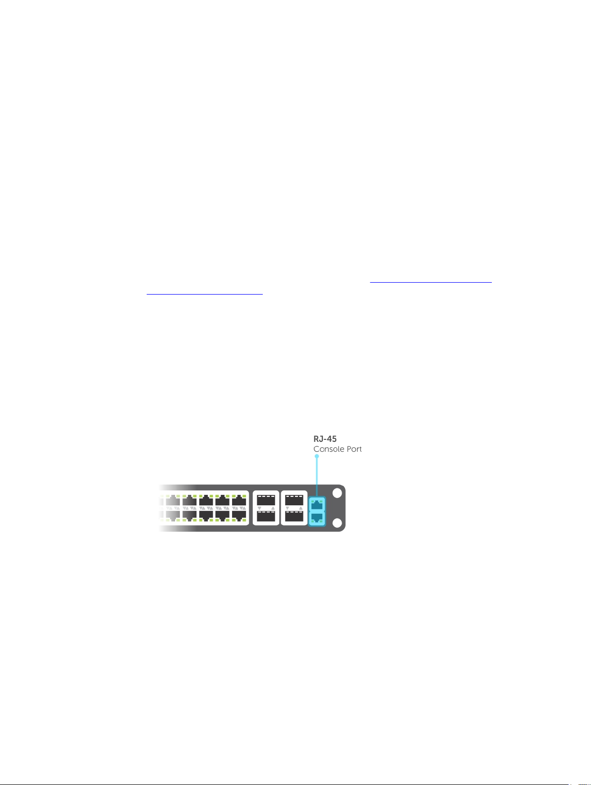
3
Getting Started
This chapter describes how you start configuring your system.
When you power up the chassis, the system performs a power-on self test (POST) during which the line
card status light emitting diodes (LEDs) blink green. The system then loads the Dell Networking Operating
System (OS). Boot messages scroll up the terminal window during this process. No user interaction is
required if the boot process proceeds without interruption.
When the boot process completes, the RPM and line card status LEDs remain online (green) and the
console monitor displays the EXEC mode prompt.
For details about using the command line interface (CLI), refer to the Accessing the Command Line
section in the Configuration Fundamentals chapter.
Console Access
The S4810 has two management ports available for system access: a serial console port and an out-ofbounds (OOB) port.
Serial Console
The RJ-45/RS-232 console port is labeled on the S4810 chassis. It is in the upper right-hand side, as you
face the I/O side of the chassis.
Figure 1. RJ-45 Console Port
1. RJ-45 Console Port
46
Getting Started
Page 47

Accessing the Console Port
To access the console port, follow these steps:
For the console port pinout, refer to Accessing the RJ-45 Console Port with a DB-9 Adapter.
1. Install an RJ-45 copper cable into the console port.Use a rollover (crossover) cable to connect the
S4810 console port to a terminal server.
2. Connect the other end of the cable to the DTE terminal server.
3. Terminal settings on the console port cannot be changed in the software and are set as follows:
• 9600 baud rate
• No parity
• 8 data bits
• 1 stop bit
• No flow control
Pin Assignments
You can connect to the console using a RJ-45 to RJ-45 rollover cable and a RJ-45 to DB-9 female DTE
adapter to a terminal server (for example, a PC).
The pin assignments between the console and a DTE terminal server are as follows:
Table 2. Pin Assignments Between the Console and a DTE Terminal Server
Console Port RJ-45 to RJ-45
Rollover Cable
Signal RJ-45 Pinout RJ-45 Pinout DB-9 Pin Signal
RTS 1 8 8 CTS
NC 2 7 6 DSR
TxD 3 6 2 RxD
GND 4 5 5 GND
GND 5 4 5 GND
RxD 6 3 3 TxD
NC 7 2 4 DTR
CTS 8 1 7 RTS
RJ-45 to RJ-45
Rollover Cable
RJ-45 to DB-9
Adapter
Terminal Server
Device
Accessing the CLI Interface and Running Scripts Using SSH
S4810
In addition to the capability to access a device using a console connection or a Telnet session, you can
also use SSH for secure, protected communication with the device. You can open an SSH session and run
commands or script files. This method of connectivity is supported with S4810, S4820T, and Z9000
switches and provides a reliable, safe communication mechanism.
Getting Started
47
Page 48

Entering CLI commands Using an SSH Connection
You can run CLI commands by entering any one of the following syntax to connect to a switch using the
preconfigured user credentials using SSH:
ssh username@hostname <CLI Command>
or
echo <CLI Command> | ssh admin@hostname
The SSH server transmits the terminal commands to the CLI shell and the results are displayed on the
screen non-interactively.
Executing Local CLI Scripts Using an SSH Connection
You can execute CLI commands by entering a CLI script in one of the following ways:
ssh username@hostname <CLIscript.file>
or
cat < CLIscript.file > | ssh admin@hostname
The script is run and the actions contained in the script are performed.
Following are the points to remember, when you are trying to establish an SSH session to the device to
run commands or script files:
• There is an upper limit of 10 concurrent sessions in SSH. Therefore, you might expect a failure in
executing SSH-related scripts.
• To avoid denial of service (DoS) attacks, a rate-limit of 10 concurrent sessions per minute in SSH is
devised. Therefore, you might experience a failure in executing SSH-related scripts when multiple
short SSH commands are executed.
• If you issue an interactive command in the SSH session, the behavior may not really be interactive.
• In some cases, when you use an SSH session, when certain show commands such as show tech-
support
truncated and not displayed. This may cause one of the commands to fail for syntax error. In such
cases, if you add few newline characters before the failed command, the output displays completely.
Execution of commands on CLI over SSH does not notice the errors that have occurred while executing
the command. As a result, you cannot identify, whether a command has failed to be processed. The
console output though is redirected back over SSH.
produce large volumes of output, sometimes few characters from the output display are
48
Getting Started
Page 49

Default Configuration
A version of Dell Networking OS is pre-loaded onto the chassis; however, the system is not configured
when you power up for the first time (except for the default hostname, which is Dell). You must
configure the system using the CLI.
Configuring a Host Name
The host name appears in the prompt. The default host name is Dell.
• Host names must start with a letter and end with a letter or digit.
• Characters within the string can be letters, digits, and hyphens.
To create a host name, use the following command.
• Create a host name.
CONFIGURATION mode
hostname name
Example of the hostname Command
Dell(conf)#hostname R1
R1(conf)#
Accessing the System Remotely
You can configure the system to access it remotely by Telnet or SSH.
• The S4810 has a dedicated management port and a management routing table that is separate from
the IP routing table.
• You can manage all Dell Networking products in-band via the front-end data ports through interfaces
assigned an IP address as well.
Accessing the S4810 and Remotely
Configuring the system for Telnet is a three-step process, as described in the following topics:
1. Configure an IP address for the management port. Configure the Management Port IP Address
2. Configure a management route with a default gateway. Configure a Management Route
3. Configure a username and password. Configure a Username and Password
Getting Started
49
Page 50

Configure the Management Port IP Address
To access the system remotely, assign IP addresses to the management ports.
1. Enter INTERFACE mode for the Management port.
CONFIGURATION mode
interface ManagementEthernet slot/port
• slot: the range is from 0 to 11.
• port: the range is 0.
2. Assign an IP address to the interface.
INTERFACE mode
ip address ip-address/mask
• ip-address: an address in dotted-decimal format (A.B.C.D).
• mask: a subnet mask in /prefix-length format (/ xx).
3. Enable the interface.
INTERFACE mode
no shutdown
Configure a Management Route
Define a path from the system to the network from which you are accessing the system remotely.
Management routes are separate from IP routes and are only used to manage the system through the
management port.
To configure a management route, use the following command.
• Configure a management route to the network from which you are accessing the system.
CONFIGURATION mode
management route ip-address/mask gateway
– ip-address: the network address in dotted-decimal format (A.B.C.D).
– mask: a subnet mask in /prefix-length format (/ xx).
– gateway: the next hop for network traffic originating from the management port.
Configuring a Username and Password
To access the system remotely, configure a system username and password.
To configure a system username and password, use the following command.
• Configure a username and password to access the system remotely.
CONFIGURATION mode
username username password [encryption-type] password
– encryption-type: specifies how you are inputting the password, is 0 by default, and is not
required.
* 0 is for inputting the password in clear text.
50
Getting Started
Page 51

* 7 is for inputting a password that is already encrypted using a Type 7 hash. Obtaining the
encrypted password from the configuration of another Dell Networking system.
Configuring the Enable Password
Access EXEC Privilege mode using the enable command. EXEC Privilege mode is unrestricted by default.
Configure a password as a basic security measure.
There are two types of enable passwords:
• enable password stores the password in the running/startup configuration using a DES encryption
method.
• enable secret is stored in the running/startup configuration in using a stronger, MD5 encryption
method.
Dell Networking recommends using the enable secret password.
To configure an enable password, use the following command.
• Create a password to access EXEC Privilege mode.
CONFIGURATION mode
enable [password | secret] [level level] [encryption-type] password
– level: is the privilege level, is 15 by default, and is not required
– encryption-type: specifies how you are inputting the password, is 0 by default, and is not
required.
* 0 is for inputting the password in clear text.
* 7 is for inputting a password that is already encrypted using a DES hash. Obtain the encrypted
password from the configuration file of another Dell Networking system.
* 5 is for inputting a password that is already encrypted using an MD5 hash. Obtain the
encrypted password from the configuration file of another Dell Networking system.
Configuration File Management
Files can be stored on and accessed from various storage media. Rename, delete, and copy files on the
system from EXEC Privilege mode.
Copy Files to and from the System
The command syntax for copying files is similar to UNIX. The copy command uses the format copy
source-file-url destination-file-url.
NOTE: For a detailed description of the copy command, refer to the Dell Networking OS Command
Reference.
• To copy a local file to a remote system, combine the file-origin syntax for a local file location with the
file-destination syntax for a remote file location.
• To copy a remote file to Dell Networking system, combine the file-origin syntax for a remote file
location with the file-destination syntax for a local file location.
Getting Started
51
Page 52

Table 3. Forming a copy Command
Location source-file-url Syntax destination-file-url Syntax
For a remote file location:
FTP server
For a remote file location:
TFTP server
For a remote file location:
SCP server
copy ftp://
username:password@{hostip
| hostname}/filepath/
filename
copy tftp://{hostip |
hostname}/filepath/
filename
copy scp://{hostip |
hostname}/filepath/
filename
ftp://
username:password@{hostip
| hostname}/ filepath/
filename
tftp://{hostip |
hostname}/filepath/
filename
scp://{hostip |
hostname}/filepath/
filename
Important Points to Remember
• You may not copy a file from one remote system to another.
• You may not copy a file from one location to the same location.
• When copying to a server, you can only use a hostname if a domain name server (DNS) server is
configured.
Example of Copying a File to an FTP Server
Dell#copy flash://Dell-EF-8.2.1.0.bin ftp://myusername:mypassword@10.10.10.10/
/Dell/Dell-EF-8.2.1.0
!!!!!!!!!!!!!!!!!!!!!!!!!!!!!!!!!!!!!!!!!!!!!!!!!!!!!!!!!!!!!!!!!!!!!!!!!!!!!
27952672 bytes successfully copied
Example of Importing a File to the Local System
core1#$//copy ftp://myusername:mypassword@10.10.10.10//Dell/
Dell-EF-8.2.1.0.bin flash://
Destination file name [Dell-EF-8.2.1.0.bin.bin]:
!!!!!!!!!!!!!!!!!!!!!!!!!!!!!!!!!!!!!!!!!!!!!!!!!!!!!!!!!!!!!!!!
26292881 bytes successfully copied
Save the Running-Configuration
The running-configuration contains the current system configuration. Dell Networking recommends
coping your running-configuration to the startup-configuration.
The commands in this section follow the same format as those commands in the Copy Files to and from
the System section but use the filenames startup-configuration and running-configuration. These
commands assume that current directory is the internal flash, which is the system default.
• Save the running-configuration to the startup-configuration on the internal flash of the primary RPM.
EXEC Privilege mode
copy running-config startup-config
• Save the running-configuration to the internal flash on an RPM.
EXEC Privilege mode
copy running-config rpm{0|1}flash://filename
• Save the running-configuration to an FTP server.
52
Getting Started
Page 53

EXEC Privilege mode
copy running-config ftp:// username:password@{hostip | hostname}/filepath/
filename
• Save the running-configuration to a TFTP server.
EXEC Privilege mode
copy running-config tftp://{hostip | hostname}/ filepath/filename
• Save the running-configuration to an SCP server.
EXEC Privilege mode
copy running-config scp://{hostip | hostname}/ filepath/filename
NOTE: When copying to a server, a host name can only be used if a DNS server is configured.
Configure the Overload Bit for a Startup Scenario
For information about setting the router overload bit for a specific period of time after a switch reload is
implemented, refer to the Intermediate System to Intermediate System (IS-IS) section in the Dell
Networking OS Command Line Reference Guide
.
Viewing Files
You can only view file information and content on local file systems.
To view a list of files or the contents of a file, use the following commands.
• View a list of files on the internal flash.
EXEC Privilege mode
dir flash:
• View the running-configuration.
EXEC Privilege mode
show running-config
• View the startup-configuration.
EXEC Privilege mode
show startup-config
Example of the dir Command
The output of the dir command also shows the read/write privileges, size (in bytes), and date of
modification for each file.
Dell#dir
Directory of flash:
1 drw- 32768 Jan 01 1980 00:00:00 .
2 drwx 512 Jul 23 2007 00:38:44 ..
3 drw- 8192 Mar 30 1919 10:31:04 TRACE_LOG_DIR
4 drw- 8192 Mar 30 1919 10:31:04 CRASH_LOG_DIR
5 drw- 8192 Mar 30 1919 10:31:04 NVTRACE_LOG_DIR
6 drw- 8192 Mar 30 1919 10:31:04 CORE_DUMP_DIR
7 d--- 8192 Mar 30 1919 10:31:04 ADMIN_DIR
8 -rw- 33059550 Jul 11 2007 17:49:46 FTOS-EF-7.4.2.0.bin
Getting Started
53
Page 54

9 -rw- 27674906 Jul 06 2007 00:20:24 FTOS-EF-4.7.4.302.bin
10 -rw- 27674906 Jul 06 2007 19:54:52 boot-image-FILE
11 drw- 8192 Jan 01 1980 00:18:28 diag
12 -rw- 7276 Jul 20 2007 01:52:40 startup-config.bak
13 -rw- 7341 Jul 20 2007 15:34:46 startup-config
14 -rw- 27674906 Jul 06 2007 19:52:22 boot-image
15 -rw- 27674906 Jul 06 2007 02:23:22 boot-flash
--More--
View Configuration Files
Configuration files have three commented lines at the beginning of the file, as shown in the following
example, to help you track the last time any user made a change to the file, which user made the
changes, and when the file was last saved to the startup-configuration.
In the running-configuration file, if there is a difference between the timestamp on the “Last
configuration change” and “Startup-config last updated,” you have made changes that have not been
saved and are preserved after a system reboot.
Example of the show running-config Command
Dell#show running-config
Current Configuration ...
! Version 9.4(0.0)
! Last configuration change at Tue Mar 11 21:33:56 2014 by admin
! Startup-config last updated at Tue Mar 11 12:11:00 2014 by default
!
boot system stack-unit 0 primary system: B:
boot system stack-unit 0 secondary tftp://10.16.127.35/dt-maa-s4810-2
boot system stack-unit 0 default tftp://10.16.127.35/dt-maa-s4810-2
boot system gateway 10.16.130.254
!
Page 57 - Under Managing the File System, the word external Flash must be
removed
Page 57 - The output of show file-systems must be modified as follows.
Dell#show file-systems
Size(b) Free(b) Feature Type Flags Prefixes
2056916992 2056540160 FAT32 USERFLASH rw flash:
- - - network rw ftp:
- - - network rw tftp:
- - - network rw scp:
Dell#
Compressing Configuration Files
The functionality to optimize and reduce the sizes of the configuration files is supported on the S4810
platform.
You can compress the running configuration by grouping all the VLANs and the physical interfaces with
the same property. Support to store the operating configuration to the startup config in the compressed
mode and to perform an image downgrade without any configuration loss are provided.
You can create groups of VLANs using the interface group command. This command will create
non-existant VLANs specified in a range. On successful command execution, the CLI switches to the
interface group context. The configuration commands inside the group context will be the similar to that
of the existing range command.
54
Getting Started
Page 55

Two existing exec mode CLIs are enhanced to display and store the running configuration in the
compressed mode.
show running-config compressed and write memory compressed
The compressed configuration will group all the similar looking configuration thereby reducing the size
of the configuration. For this release, the compression will be done only for interface related
configuration (VLAN & physical interfaces)
The following table describes how the standard and the compressed configuration differ:
int vlan 2
no ip address
no shut
int vlan 3
tagged te 0/0
no ip address
shut
int te 0/ 0
no ip address
switchport
int te 0/2
no ip address
shut
shut
Dell# show running-config
<snip>
!
interface TenGigabitEthernet 0/0
no ip address
switchport
shutdown
int vlan 4
tagged te 0/0
no ip address
shut
int te 0/3
no ip address
shut
int vlan 5
tagged te 0/0
int vlan 100
no ip address
int vlan 1000
ip address
1.1.1.1/16
no ip address
no shut
no shut
shut
int te 0/4
no ip address
int te 0/10
no ip address
int te 0/34
ip address
2.1.1.1/16
shut
shut
shut
Dell# show running-config compressed
<snip>
!
interface TenGigabitEthernet 0/0
no ip address
switchport
shutdown
!
interface TenGigabitEthernet 0/2
no ip address
shutdown
!
interface TenGigabitEthernet 0/3
no ip address
shutdown
!
Getting Started
!
Interface group TenGigabitEthernet 0/2 – 4 ,
TenGigabitEthernet 0/10
no ip address
shutdown
!
interface TenGigabitEthernet 0/34
ip address 2.1.1.1/16
shutdown
!
55
Page 56

interface TenGigabitEthernet 0/4
interface group Vlan 2 , Vlan 100
no ip address
shutdown
!
interface TenGigabitEthernet 0/10
no ip address
shutdown
!
interface TenGigabitEthernet 0/34
ip address 2.1.1.1/16
shutdown
!
interface Vlan 2
no ip address
no shutdown
!
no ip address
no shutdown
!
interface group Vlan 3 – 5
tagged te 0/0
no ip address
shutdown
!
interface Vlan 1000
ip address 1.1.1.1/16
no shutdown
!
<snip>
Compressed config size – 27 lines.
interface Vlan 3
tagged te 0/0
no ip address
shutdown
!
interface Vlan 4
tagged te 0/0
no ip address
shutdown
!
interface Vlan 5
tagged te 0/0
no ip address
shutdown
56
Getting Started
Page 57

!
interface Vlan 100
no ip address
no shutdown
!
interface Vlan 1000
ip address 1.1.1.1/16
no shutdown
Uncompressed config size – 52 lines
write memory compressed
The write memory compressed CLI will write the operating configuration to the startup-config file in the
compressed mode. In stacking scenario, it will also take care of syncing it to all the standby and member
units.
The following is the sample output:
Dell#write memory compressed
!
Jul 30 08:50:26: %STKUNIT0-M:CP %FILEMGR-5-FILESAVED: Copied running-config to
startup-config in flash by default
copy compressed-config
Copy one file, after optimizing and reducing the size of the configuration file, to another location. Dell
Networking OS supports IPv4 and IPv6 addressing for FTP, TFTP, and SCP (in the hostip field).
Managing the File System
The Dell Networking system can use the internal Flash, external Flash, or remote devices to store files.
The system stores files on the internal Flash by default but can be configured to store files elsewhere.
To view file system information, use the following command.
• View information about each file system.
EXEC Privilege mode
show file-systems
The output of the show file-systems command in the following example shows the total capacity,
amount of free memory, file structure, media type, read/write privileges for each storage device in use.
Dell#show file-systems
Size(b) Free(b) Feature Type Flags Prefixes
520962048 213778432 dosFs2.0 USERFLASH rw flash:
127772672 21936128 dosFs2.0 USERFLASH rw slot0:
Getting Started
57
Page 58

- - - network rw ftp:
- - - network rw tftp:
- - - network rw scp:
You can change the default file system so that file management commands apply to a particular device
or memory.
To change the default directory, use the following command.
• Change the default directory.
EXEC Privilege mode
cd directory
Enabling Software Features on Devices Using a Command Option
This capability to activate software applications or components on a device using a command is
supported on the S4810, S4820T, and S6000, platforms.
Starting with Release 9.4(0.0), you can enable or disable specific software functionalities or applications
that need to run on a device by using a command attribute in the CLI interface. This capability enables
effective, streamlined management and administration of applications and utilities that run on a device.
You can employ this capability to perform an on-demand activation or turn-off of a software component
or protocol. A feature configuration file that is generated for each image contains feature names denotes
whether this enabling or disabling method is available for such features. In 9.4(0.0), you can enable or
disable the VRF application globally across the system by using this capability.
You can activate VRF application on a device by using the feature vrf command in CONFIGURATION
mode.
NOTE: The no feature vrf command is not supported on any of the platforms.
To enable the VRF feature and cause all VRF-related commands to be available or viewable in the CLI
interface, use the following command. You must enable the VRF feature before you can configure its
related attributes.
Dell(conf)# feature vrf
Based on whether VRF feature is identified as supported in the Feature Configuration file, configuration
command feature vrf becomes available for usage. This command will be stored in running-configuration
and will precede all other VRF-related configurations.
NOTE: The MXL and Z9000 platforms currently do not support VRF. These platforms support only
the management and default VRFs, which are available by default. As a result, the feature vrf
command is not available for these platforms.
To display the state of Dell Networking OS features:
Dell#show feature
Example of show feature output
58
Getting Started
Page 59

For a particular target where VRF is enabled, the show output is similar to the following:
Feature State
------------------------------
VRF enabled
View Command History
The command-history trace feature captures all commands entered by all users of the system with a time
stamp and writes these messages to a dedicated trace log buffer.
The system generates a trace message for each executed command. No password information is saved
to the file.
To view the command-history trace, use the show command-history command.
Example of the show command-history Command
Dell#show command-history
[12/5 10:57:8]: CMD-(CLI):service password-encryption
[12/5 10:57:12]: CMD-(CLI):hostname Force10
[12/5 10:57:12]: CMD-(CLI):ip telnet server enable
[12/5 10:57:12]: CMD-(CLI):line console 0
[12/5 10:57:12]: CMD-(CLI):line vty 0 9
[12/5 10:57:13]: CMD-(CLI):boot system rpm0 primary flash://FTOSCB-1.1.1.2E2.bin
Upgrading Dell Networking OS
NOTE: To upgrade Dell Networking Operating System (OS), refer to the Release Notes for the
version you want to load on the system.
Using Hashes to Validate Software Images
You can use the MD5 message-digest algorithm or SHA256 Secure Hash Algorithm to validate the
software image on the flash drive, after the image has been transferred to the system, but before the
image has been installed. The validation calculates a hash value of the downloaded image file on system’s
flash drive, and, optionally, compares it to a Dell Networking published hash for that file.
The MD5 or SHA256 hash provides a method of validating that you have downloaded the original
software. Calculating the hash on the local image file, and comparing the result to the hash published for
that file on iSupport, provides a high level of confidence that the local copy is exactly the same as the
published software image. This validation procedure, and the verify {md5 | sha256} command to support
it, can prevent the installation of corrupted or modified images.
The verify {md5 | sha256} command calculates and displays the hash of any file on the specified local
flash drive. You can compare the displayed hash against the appropriate hash published on i-Support.
Optionally, the published hash can be included in the verify {md5 | sha256} command, which will display
whether it matches the calculated hash of the indicated file.
To validate a software image:
Getting Started
59
Page 60

1. Download Dell Networking OS software image file from the iSupport page to the local (FTP or TFTP)
server. The published hash for that file is displayed next to the software image file on the iSupport
page.
2. Go on to the Dell Networking system and copy the software image to the flash drive, using the copy
command.
3. Run the verify {md5 | sha256} [ flash://]img-file [hash-value] command. For example, verify sha256
flash://FTOS-SE-9.5.0.0.bin
4. Compare the generated hash value to the expected hash value published on the iSupport page.
To validate the software image on the flash drive after the image has been transferred to the system, but
before the image has been installed, use the verify {md5 | sha256} [ flash://]img-file [hash-value]
command in EXEC mode.
• md5: MD5 message-digest algorithm
• sha256: SHA256 Secure Hash Algorithm
• flash: (Optional) Specifies the flash drive. The default is to use the flash drive. You can just enter the
image file name.
• hash-value: (Optional). Specify the relevant hash published on i-Support.
• img-file: Enter the name of the Dell Networking software image file to validate
Examples: Without Entering the Hash Value for Verification
MD5
Dell# verify md5 flash://FTOS-SE-9.5.0.0.bin
MD5 hash for FTOS-SE-9.5.0.0.bin: 275ceb73a4f3118e1d6bcf7d75753459
SHA256
Dell# verify sha256 flash://FTOS-SE-9.5.0.0.bin
SHA256 hash for FTOS-SE-9.5.0.0.bin:
e6328c06faf814e6899ceead219afbf9360e986d692988023b749e6b2093e933
Examples: Entering the Hash Value for Verification
MD5
Dell# verify md5 flash://FTOS-SE-9.5.0.0.bin 275ceb73a4f3118e1d6bcf7d75753459
MD5 hash VERIFIED for FTOS-SE-9.5.0.0.bin
SHA256
Dell# verify sha256 flash://FTOS-SE-9.5.0.0.bin
e6328c06faf814e6899ceead219afbf9360e986d692988023b749e6b2093e933
SHA256 hash VERIFIED for FTOS-SE-9.5.0.0.bin
Using HTTP for File Transfers
Stating with Release 9.3(0.1), you can use HTTP to copy files or configuration details to a remote server.
Use the copy source-file-url http://host[:port]/file-path command to transfer files to an external server.
This functionality to transport files using HTTP to a remote server is supported on MXL, I/O Aggregator,
S4810, S4820, S6000, and Z9000 platforms.
Enter the following source-file-url keywords and information:
60
Getting Started
Page 61

• To copy a file from the internal FLASH, enter flash:// followed by the filename.
• To copy the running configuration, enter the keyword running-config.
• To copy the startup configuration, enter the keyword startup-config.
• To copy a file on the external FLASH, enter usbflash:// followed by the filename.
Getting Started
61
Page 62

4
Management
Management is supported on the S4810 platform.
This chapter describes the different protocols or services used to manage the Dell Networking system.
Configuring Privilege Levels
Privilege levels restrict access to commands based on user or terminal line.
There are 16 privilege levels, of which three are pre-defined. The default privilege level is 1.
Level Description
Level 0 Access to the system begins at EXEC mode, and EXEC mode commands are
limited to enable, disable, and exit.
Level 1 Access to the system begins at EXEC mode, and all commands are available.
Level 15 Access to the system begins at EXEC Privilege mode, and all commands are
available.
Creating a Custom Privilege Level
Custom privilege levels start with the default EXEC mode command set. You can then customize privilege
levels 2-14 by:
• restricting access to an EXEC mode command
• moving commands from EXEC Privilege to EXEC mode
• restricting access
A user can access all commands at his privilege level and below.
Removing a Command from EXEC Mode
To remove a command from the list of available commands in EXEC mode for a specific privilege level,
use the privilege exec command from CONFIGURATION mode.
In the command, specify a level greater than the level given to a user or terminal line, then the first
keyword of each command you wish to restrict.
Moving a Command from EXEC Privilege Mode to EXEC Mode
To move a command from EXEC Privilege to EXEC mode for a privilege level, use the privilege exec
command from CONFIGURATION mode.
In the command, specify the privilege level of the user or terminal line and specify all keywords in the
command to which you want to allow access.
62
Management
Page 63

Allowing Access to CONFIGURATION Mode Commands
To allow access to CONFIGURATION mode, use the privilege exec level level configure
command from CONFIGURATION mode.
A user that enters CONFIGURATION mode remains at his privilege level and has access to only two
commands, end and exit. You must individually specify each CONFIGURATION mode command you
want to allow access to using the privilege configure level level command. In the command,
specify the privilege level of the user or terminal line and specify all the keywords in the command to
which you want to allow access.
Allowing Access to the Following Modes
This section describes how to allow access to the INTERFACE, LINE, ROUTE-MAP, and ROUTER modes.
Similar to allowing access to CONFIGURATION mode, to allow access to INTERFACE, LINE, ROUTE-MAP,
and ROUTER modes, you must first allow access to the command that enters you into the mode. For
example, to allow a user to enter INTERFACE mode, use the privilege configure level level
interface gigabitethernet command.
Next, individually identify the INTERFACE, LINE, ROUTE-MAP or ROUTER commands to which you want
to allow access using the privilege {interface | line | route-map | router} level
level command. In the command, specify the privilege level of the user or terminal line and specify all
the keywords in the command to which you want to allow access.
To remove, move or allow access, use the following commands.
The configuration in the following example creates privilege level 3. This level:
• removes the resequence command from EXEC mode by requiring a minimum of privilege level 4
• moves the capture bgp-pdu max-buffer-size command from EXEC Privilege to EXEC mode by
requiring a minimum privilege level 3, which is the configured level for VTY 0
• allows access to CONFIGURATION mode with the banner command
• allows access to INTERFACE and LINE modes are allowed with no commands
• Remove a command from the list of available commands in EXEC mode.
CONFIGURATION mode
privilege exec level level {command ||...|| command}
• Move a command from EXEC Privilege to EXEC mode.
CONFIGURATION mode
privilege exec level level {command ||...|| command}
• Allow access to CONFIGURATION mode.
CONFIGURATION mode
privilege exec level level configure
• Allow access to INTERFACE, LINE, ROUTE-MAP, and/or ROUTER mode. Specify all the keywords in
the command.
CONFIGURATION mode
privilege configure level level {interface | line | route-map | router}
{command-keyword ||...|| command-keyword}
Management
63
Page 64

• Allow access to a CONFIGURATION, INTERFACE, LINE, ROUTE-MAP, and/or ROUTER mode
command.
CONFIGURATION mode
privilege {configure |interface | line | route-map | router} level level
{command ||...|| command}
Example of EXEC Privilege Commands
Dell(conf)#do show run priv
!
privilege exec level 3 capture
privilege exec level 3 configure
privilege exec level 4 resequence
privilege exec level 3 capture bgp-pdu
privilege exec level 3 capture bgp-pdu max-buffer-size
privilege configure level 3 line
privilege configure level 3 interface
Dell(conf)#do telnet 10.11.80.201
[telnet output omitted]
Dell#show priv
Current privilege level is 3.
Dell#?
capture Capture packet
configure Configuring from terminal
disable Turn off privileged commands
enable Turn on privileged commands
exit Exit from the EXEC
ip Global IP subcommands
monitor Monitoring feature
mtrace Trace reverse multicast path from destination to source
ping Send echo messages
quit Exit from the EXEC
show Show running system information
[output omitted]
Dell#config
[output omitted]
Dell(conf)#do show priv
Current privilege level is 3.
Dell(conf)#?
end Exit from configuration mode
exit Exit from configuration mode
interface Select an interface to configure
line Configure a terminal line
linecard Set line card type
Dell(conf)#interface ?
fastethernet Fast Ethernet interface
gigabitethernet Gigabit Ethernet interface
loopback Loopback interface
managementethernet Management Ethernet interface
null Null interface
port-channel Port-channel interface
range Configure interface range
sonet SONET interface
tengigabitethernet TenGigabit Ethernet interface
vlan VLAN interface
Dell(conf)#interface gigabitethernet 1/1
Dell(conf-if-gi-1/1)#?
end Exit from configuration mode
exit Exit from interface configuration mode
Dell(conf-if-gi-1/1)#exit
Dell(conf)#line ?
64
Management
Page 65

aux Auxiliary line
console Primary terminal line
vty Virtual terminal
Dell(conf)#line vty 0
Dell(config-line-vty)#?
exit Exit from line configuration mode
Dell(config-line-vty)#
Dell(conf)#interface group ?
fortyGigE FortyGigabit Ethernet interface
gigabitethernet GigabitEthernet interface IEEE 802.3z
tengigabitethernet TenGigabit Ethernet interface
vlan VLAN keyword
Dell(conf)# interface group vlan 1 - 2 , tengigabitethernet 0/0
Dell(conf-if-group-vl-1-2,te-0/0)# no shutdown
Dell(conf-if-group-vl-1-2,te-0/0)# end
Applying a Privilege Level to a Username
To set the user privilege level, use the following command.
• Configure a privilege level for a user.
CONFIGURATION mode
username username privilege level
Applying a Privilege Level to a Terminal Line
To set a privilege level for a terminal line, use the following command.
• Configure a privilege level for a user.
CONFIGURATION mode
username username privilege level
NOTE: When you assign a privilege level between 2 and 15, access to the system begins at EXEC
mode, but the prompt is
hostname#, rather than hostname>.
Configuring Logging
The Dell Networking OS tracks changes in the system using event and error messages.
By default, Dell Networking OS logs these messages on:
• the internal buffer
• console and terminal lines
• any configured syslog servers
To disable logging, use the following commands.
• Disable all logging except on the console.
CONFIGURATION mode
no logging on
• Disable logging to the logging buffer.
CONFIGURATION mode
no logging buffer
Management
65
Page 66

• Disable logging to terminal lines.
CONFIGURATION mode
no logging monitor
• Disable console logging.
CONFIGURATION mode
no logging console
Audit and Security Logs
This section describes how to configure, display, and clear audit and security logs.
The following is the configuration task list for audit and security logs:
• Enabling Audit and Security Logs
• Displaying Audit and Security Logs
• Clearing Audit Logs
Enabling Audit and Security Logs
You enable audit and security logs to monitor configuration changes or determine if these changes affect
the operation of the system in the network. You log audit and security events to a system log server,
using the
without RBAC enabled. For information about RBAC, see Role-Based Access Control.
logging extended command in CONFIGURATION mode. This command is available with or
Audit Logs
The audit log contains configuration events and information. The types of information in this log consist
of the following:
• User logins to the switch.
• System events for network issues or system issues.
• Users making configuration changes. The switch logs who made the configuration changes and the
date and time of the change. However, each specific change on the configuration is not logged. Only
that the configuration was modified is logged with the user ID, date, and time of the change.
• Uncontrolled shutdown.
Security Logs
The security log contains security events and information. RBAC restricts access to audit and security logs
based on the CLI sessions’ user roles. The types of information in this log consist of the following:
• Establishment of secure traffic flows, such as SSH.
• Violations on secure flows or certificate issues.
• Adding and deleting of users.
• User access and configuration changes to the security and crypto parameters (not the key
information but the crypto configuration)
Important Points to Remember
66
Management
Page 67

When you enabled RBAC and extended logging:
• Only the system administrator user role can execute this command.
• The system administrator and system security administrator user roles can view security events and
system events.
• The system administrator user roles can view audit, security, and system events.
• Only the system administrator and security administrator user roles can view security logs.
• The network administrator and network operator user roles can view system events.
NOTE: If extended logging is disabled, you can only view system events, regardless of RBAC user
role.
Example of Enabling Audit and Security Logs
Dell(conf)#logging extended
Displaying Audit and Security Logs
To display audit logs, use the show logging auditlog command in Exec mode. To view these logs,
you must first enable the logging extended command. Only the RBAC system administrator user role can
view the audit logs. Only the RBAC security administrator and system administrator user role can view the
security logs. If extended logging is disabled, you can only view system events, regardless of RBAC user
role. To view security logs, use the
Example of the show logging auditlog Command
For information about the logging extended command, see Enabling Audit and Security Logs
show logging command.
Dell#show logging auditlog
May 12 12:20:25: Dell#: %CLI-6-logging extended by admin from vty0 (10.14.1.98)
May 12 12:20:42: Dell#: %CLI-6-configure terminal by admin from vty0
(10.14.1.98)
May 12 12:20:42: Dell#: %CLI-6-service timestamps log datetime by admin from
vty0 (10.14.1.98)
Example of the show logging Command for Security
For information about the logging extended command, see Enabling Audit and Security Logs
Dell#show logging
Jun 10 04:23:40: %STKUNIT0-M:CP
user admin on line vty0 ( 10.14.1.91 )
%SEC-5-LOGIN_SUCCESS: Login successful for
Clearing Audit Logs
To clear audit logs, use the clear logging auditlog command in Exec mode. When RBAC is
enabled, only the system administrator user role can issue this command.
Example of the clear logging auditlog Command
Dell# clear logging auditlog
Configuring Logging Format
To display syslog messages in a RFC 3164 or RFC 5424 format, use the logging version [0 | 1}
command in CONFIGURATION mode. By default, the system log version is set to 0.
Management
67
Page 68

The following describes the two log messages formats:
• 0 – Displays syslog messages format as described in RFC 3164, The BSD syslog Protocol
• 1 – Displays syslog message format as described in RFC 5424, The SYSLOG Protocol
Example of Configuring the Logging Message Format
Dell(conf)#logging version ?
<0-1> Select syslog version (default = 0)
Dell(conf)#logging version 1
Display the Logging Buffer and the Logging Configuration
To display the current contents of the logging buffer and the logging settings for the system, use the
show logging command in EXEC privilege mode. When RBAC is enabled, the security logs are filtered
based on the user roles. Only the security administrator and system administrator can view the security
logs.
Example of the show logging Command
Dell#show logging
syslog logging: enabled
Console logging: level Debugging
Monitor logging: level Debugging
Buffer logging: level Debugging, 40 Messages Logged, Size (40960 bytes)
Trap logging: level Informational
%IRC-6-IRC_COMMUP: Link to peer RPM is up
%RAM-6-RAM_TASK: RPM1 is transitioning to Primary RPM.
%RPM-2-MSG:CP1 %POLLMGR-2-MMC_STATE: External flash disk missing in 'slot0:'
%CHMGR-5-CARDDETECTED: Line card 0 present
%CHMGR-5-CARDDETECTED: Line card 2 present
%CHMGR-5-CARDDETECTED: Line card 4 present
%CHMGR-5-CARDDETECTED: Line card 5 present
%CHMGR-5-CARDDETECTED: Line card 8 present
%CHMGR-5-CARDDETECTED: Line card 10 present
%CHMGR-5-CARDDETECTED: Line card 12 present
%TSM-6-SFM_DISCOVERY: Found SFM 0
%TSM-6-SFM_DISCOVERY: Found SFM 1
%TSM-6-SFM_DISCOVERY: Found SFM 2
%TSM-6-SFM_DISCOVERY: Found SFM 3
%TSM-6-SFM_DISCOVERY: Found SFM 4
%TSM-6-SFM_DISCOVERY: Found SFM 5
%TSM-6-SFM_DISCOVERY: Found SFM 6
%TSM-6-SFM_DISCOVERY: Found SFM 7
%TSM-6-SFM_SWITCHFAB_STATE: Switch Fabric: UP
%TSM-6-SFM_DISCOVERY: Found SFM 8
%TSM-6-SFM_DISCOVERY: Found 9 SFMs
%CHMGR-5-CHECKIN: Checkin from line card 5 (type EX1YB, 1 ports)
%TSM-6-PORT_CONFIG: Port link status for LC 5 => portpipe 0: OK portpipe 1: N/A
%CHMGR-5-LINECARDUP: Line card 5 is up
%CHMGR-5-CHECKIN: Checkin from line card 12 (type S12YC12, 12 ports)
%TSM-6-PORT_CONFIG: Port link status for LC 12 => portpipe 0: OK portpipe 1: N/A
%CHMGR-5-LINECARDUP: Line card 12 is up
%IFMGR-5-CSTATE_UP: changed interface Physical state to up: So 12/8
%IFMGR-5-CSTATE_DN: changed interface Physical state to down: So 12/8
To view any changes made, use the show running-config logging command in EXEC privilege
mode, as shown in the example for Configure a UNIX Logging Facility Level.
68
Management
Page 69

Setting Up a Secure Connection to a Syslog Server
You can use reverse tunneling with the port forwarding to securely connect to a syslog server.
Pre-requisites
To configure a secure connection from the switch to the syslog server:
1. On the switch, enable the SSH server
Dell(conf)#ip ssh server enable
2. On the syslog server, create a reverse SSH tunnel from the syslog server to FTOS switch, using
following syntax:
ssh -R <remote port>:<syslog server>:<syslog server listen port>
user@remote_host -nNf
In the following example the syslog server IP address is 10.156.166.48 and the listening port is
5141. The switch IP address is 10.16.131.141 and the listening port is 5140
ssh -R 5140:10.156.166.48:5141 admin@10.16.131.141 -nNf
Management
69
Page 70

3. Configure logging to a local host. locahost is “127.0.0.1” or “::1”.
If you do not, the system displays an error when you attempt to enable role-based only AAA
authorization.
Dell(conf)# logging localhost tcp port
Dell(conf)#logging 127.0.0.1 tcp 5140
Sending System Messages to a Syslog Server
To send system messages to a specified syslog server, use the following command. The following syslog
standards are supported: RFC 5424 The SYSLOG Protocol, R.Gerhards and Adiscon GmbH, March 2009,
obsoletes RFC 3164 and RFC 5426 Transmission of Syslog Messages over UDP.
• Specify the server to which you want to send system messages. You can configure up to eight syslog
servers.
CONFIGURATION mode
logging {ip-address | ipv6-address | hostname} {{udp {port}} | {tcp {port}}}
In the release 9.4.(0.0), exporting of Syslogs to external servers that are connected through different
VRFs is supported.
Log Messages in the Internal Buffer
All error messages, except those beginning with %BOOTUP (Message), are log in the internal buffer.
For example, %BOOTUP:RPM0:CP %PORTPIPE-INIT-SUCCESS: Portpipe 0 enabled
Configuration Task List for System Log Management
There are two configuration tasks for system log management:
• Disable System Logging
• Send System Messages to a Syslog Server
Disabling System Logging
By default, logging is enabled and log messages are sent to the logging buffer, all terminal lines, the
console, and the syslog servers.
To disable system logging, use the following commands.
• Disable all logging except on the console.
CONFIGURATION mode
no logging on
• Disable logging to the logging buffer.
CONFIGURATION mode
no logging buffer
• Disable logging to terminal lines.
CONFIGURATION mode
no logging monitor
70
Management
Page 71

• Disable console logging.
CONFIGURATION mode
no logging console
Sending System Messages to a Syslog Server
To send system messages to a specified syslog server, use the following command. The following syslog
standards are supported: RFC 5424 The SYSLOG Protocol, R.Gerhards and Adiscon GmbH, March 2009,
obsoletes RFC 3164 and RFC 5426 Transmission of Syslog Messages over UDP.
• Specify the server to which you want to send system messages. You can configure up to eight syslog
servers.
CONFIGURATION mode
logging {ip-address | ipv6-address | hostname} {{udp {port}} | {tcp {port}}}
In the release 9.4.(0.0), exporting of Syslogs to external servers that are connected through different
VRFs is supported.
Configuring a UNIX System as a Syslog Server
To configure a UNIX System as a syslog server, use the following command.
• Configure a UNIX system as a syslog server by adding the following lines to /etc/syslog.conf on the
UNIX system and assigning write permissions to the file.
– Add line on a 4.1 BSD UNIX system. local7.debugging /var/log/ftos.log
– Add line on a 5.7 SunOS UNIX system. local7.debugging /var/adm/ftos.log
In the previous lines, local7 is the logging facility level and debugging is the severity level.
Changing System Logging Settings
You can change the default settings of the system logging by changing the severity level and the storage
location.
The default is to log all messages up to debug level, that is, all system messages. By changing the severity
level in the logging commands, you control the number of system messages logged.
To specify the system logging settings, use the following commands.
• Specify the minimum severity level for logging to the logging buffer.
CONFIGURATION mode
logging buffered level
• Specify the minimum severity level for logging to the console.
CONFIGURATION mode
logging console level
• Specify the minimum severity level for logging to terminal lines.
CONFIGURATION mode
logging monitor level
Management
71
Page 72

• Specify the minimum severity level for logging to a syslog server.
CONFIGURATION mode
logging trap level
• Specify the minimum severity level for logging to the syslog history table.
CONFIGURATION mode
logging history level
• Specify the size of the logging buffer.
CONFIGURATION mode
logging buffered size
NOTE: When you decrease the buffer size, Dell Networking OS deletes all messages stored in
the buffer. Increasing the buffer size does not affect messages in the buffer.
• Specify the number of messages that Dell Networking OS saves to its logging history table.
CONFIGURATION mode
logging history size size
To view the logging buffer and configuration, use the show logging command in EXEC privilege mode,
as shown in the example for Display the Logging Buffer and the Logging Configuration.
To view the logging configuration, use the show running-config logging command in privilege
mode, as shown in the example for Configure a UNIX Logging Facility Level.
Display the Logging Buffer and the Logging Configuration
To display the current contents of the logging buffer and the logging settings for the system, use the
show logging command in EXEC privilege mode. When RBAC is enabled, the security logs are filtered
based on the user roles. Only the security administrator and system administrator can view the security
logs.
Example of the show logging Command
Dell#show logging
syslog logging: enabled
Console logging: level Debugging
Monitor logging: level Debugging
Buffer logging: level Debugging, 40 Messages Logged, Size (40960 bytes)
Trap logging: level Informational
%IRC-6-IRC_COMMUP: Link to peer RPM is up
%RAM-6-RAM_TASK: RPM1 is transitioning to Primary RPM.
%RPM-2-MSG:CP1 %POLLMGR-2-MMC_STATE: External flash disk missing in 'slot0:'
%CHMGR-5-CARDDETECTED: Line card 0 present
%CHMGR-5-CARDDETECTED: Line card 2 present
%CHMGR-5-CARDDETECTED: Line card 4 present
%CHMGR-5-CARDDETECTED: Line card 5 present
%CHMGR-5-CARDDETECTED: Line card 8 present
%CHMGR-5-CARDDETECTED: Line card 10 present
%CHMGR-5-CARDDETECTED: Line card 12 present
%TSM-6-SFM_DISCOVERY: Found SFM 0
%TSM-6-SFM_DISCOVERY: Found SFM 1
%TSM-6-SFM_DISCOVERY: Found SFM 2
%TSM-6-SFM_DISCOVERY: Found SFM 3
%TSM-6-SFM_DISCOVERY: Found SFM 4
%TSM-6-SFM_DISCOVERY: Found SFM 5
72
Management
Page 73

%TSM-6-SFM_DISCOVERY: Found SFM 6
%TSM-6-SFM_DISCOVERY: Found SFM 7
%TSM-6-SFM_SWITCHFAB_STATE: Switch Fabric: UP
%TSM-6-SFM_DISCOVERY: Found SFM 8
%TSM-6-SFM_DISCOVERY: Found 9 SFMs
%CHMGR-5-CHECKIN: Checkin from line card 5 (type EX1YB, 1 ports)
%TSM-6-PORT_CONFIG: Port link status for LC 5 => portpipe 0: OK portpipe 1: N/A
%CHMGR-5-LINECARDUP: Line card 5 is up
%CHMGR-5-CHECKIN: Checkin from line card 12 (type S12YC12, 12 ports)
%TSM-6-PORT_CONFIG: Port link status for LC 12 => portpipe 0: OK portpipe 1: N/A
%CHMGR-5-LINECARDUP: Line card 12 is up
%IFMGR-5-CSTATE_UP: changed interface Physical state to up: So 12/8
%IFMGR-5-CSTATE_DN: changed interface Physical state to down: So 12/8
To view any changes made, use the show running-config logging command in EXEC privilege
mode, as shown in the example for
Configure a UNIX Logging Facility Level.
Configuring a UNIX Logging Facility Level
You can save system log messages with a UNIX system logging facility.
To configure a UNIX logging facility level, use the following command.
• Specify one of the following parameters.
CONFIGURATION mode
logging facility [facility-type]
– auth (for authorization messages)
– cron (for system scheduler messages)
– daemon (for system daemons)
– kern (for kernel messages)
– local0 (for local use)
– local1 (for local use)
– local2 (for local use)
– local3 (for local use)
– local4 (for local use)
– local5 (for local use)
– local6 (for local use)
– local7 (for local use)
– lpr (for line printer system messages)
– mail (for mail system messages)
– news (for USENET news messages)
– sys9 (system use)
– sys10 (system use)
– sys11 (system use)
– sys12 (system use)
– sys13 (system use)
– sys14 (system use)
– syslog (for syslog messages)
Management
73
Page 74

– user (for user programs)
– uucp (UNIX to UNIX copy protocol)
Example of the show running-config logging Command
To view nondefault settings, use the show running-config logging command in EXEC mode.
Dell#show running-config logging
!
logging buffered 524288 debugging
service timestamps log datetime msec
service timestamps debug datetime msec
!
logging trap debugging
logging facility user
logging source-interface Loopback 0
logging 10.10.10.4
Dell#
Synchronizing Log Messages
You can configure Dell Networking OS to filter and consolidate the system messages for a specific line by
synchronizing the message output.
Only the messages with a severity at or below the set level appear. This feature works on the terminal and
console connections available on the system.
1. Enter LINE mode.
CONFIGURATION mode
line {console 0 | vty number [end-number] | aux 0}
Configure the following parameters for the virtual terminal lines:
• number: the range is from zero (0) to 8.
• end-number: the range is from 1 to 8.
You can configure multiple virtual terminals at one time by entering a number and an end-number.
2. Configure a level and set the maximum number of messages to print.
LINE mode
logging synchronous [level severity-level | all] [limit]
Configure the following optional parameters:
• level severity-level: the range is from 0 to 7. The default is 2. Use the all keyword to
include all messages.
• limit: the range is from 20 to 300. The default is 20.
To view the logging synchronous configuration, use the show config command in LINE mode.
74
Management
Page 75

Enabling Timestamp on Syslog Messages
By default, syslog messages do not include a time/date stamp stating when the error or message was
created.
To enable timestamp, use the following command.
• Add timestamp to syslog messages.
CONFIGURATION mode
service timestamps [log | debug] [datetime [localtime] [msec] [show-timezone]
| uptime]
Specify the following optional parameters:
– You can add the keyword localtime to include the localtime, msec, and show-timezone. If
you do not add the keyword localtime, the time is UTC.
– uptime: To view time since last boot.
If you do not specify a parameter, Dell Networking OS configures uptime.
To view the configuration, use the show running-config logging command in EXEC privilege mode.
To disable time stamping on syslog messages, use the no service timestamps [log | debug]
command.
File Transfer Services
With Dell Networking OS, you can configure the system to transfer files over the network using the file
transfer protocol (FTP).
One FTP application is copying the system image files over an interface on to the system; however, FTP is
not supported on virtual local area network (VLAN) interfaces.
In the release 9.4.(0.0), FTP and TFTP services are enhanced to support the VRF-aware functionality. If
you want the FTP or TFTP server to use a VRF table that is attached to an interface, you must configure
the FTP or TFTP server to use a specific routing table. You can use the ip ftp vrf vrf-name or ip
tftp vrf vrf-name command to inform the FTP or TFTP server to use a specific routing table. After
you configure this setting, the VRF table is used to look up the destination address. However, these
changes are backward-compatible and do not affect existing behavior; meaning, you can still use the
source-interface command to communicate with a particular interface even if no VRF is configured
on that interface.
For more information about FTP, refer to RFC 959, File Transfer Protocol.
NOTE: To transmit large files, Dell Networking recommends configuring the switch as an FTP
server.
Configuration Task List for File Transfer Services
The configuration tasks for file transfer services are:
• Enable FTP Server (mandatory)
Management
75
Page 76

• Configure FTP Server Parameters (optional)
• Configure FTP Client Parameters (optional)
Enabling the FTP Server
To enable the system as an FTP server, use the following command.
To view FTP configuration, use the show running-config ftp command in EXEC privilege mode.
• Enable FTP on the system.
CONFIGURATION mode
ftp-server enable
Example of Viewing FTP Configuration
Dell#show running ftp
!
ftp-server enable
ftp-server username nairobi password 0 zanzibar
Dell#
Configuring FTP Server Parameters
After you enable the FTP server on the system, you can configure different parameters.
To specify the system logging settings, use the following commands.
• Specify the directory for users using FTP to reach the system.
CONFIGURATION mode
ftp-server topdir dir
The default is the internal flash directory.
• Specify a user name for all FTP users and configure either a plain text or encrypted password.
CONFIGURATION mode
ftp-server username username password [encryption-type] password
Configure the following optional and required parameters:
– username: enter a text string.
– encryption-type: enter 0 for plain text or 7 for encrypted text.
– password: enter a text string.
NOTE: You cannot use the change directory (cd) command until you have configured ftp-
server topdir.
To view the FTP configuration, use the show running-config ftp command in EXEC privilege mode.
Configuring FTP Client Parameters
To configure FTP client parameters, use the following commands.
• Enter the following keywords and slot/port or number information:
76
Management
Page 77

– For a Gigabit Ethernet interface, enter the keyword GigabitEthernet then the slot/port
information.
– For a loopback interface, enter the keyword loopback then a number between 0 and 16383.
– For a port channel interface, enter the keywords port-channel then a number from 1 to 255 for
TeraScale and ExaScale.
– For a SONET interface, enter the keyword sonet then the slot/port information.
– For a 10-Gigabit Ethernet interface, enter the keyword TenGigabitEthernet then the slot/port
information.
– For a VLAN interface, enter the keyword vlan then a number from 1 to 4094.
– For a 40-Gigabit Ethernet interface, enter the keyword fortyGigE then the slot/port information.
CONFIGURATION mode
ip ftp source-interface interface
• Configure a password.
CONFIGURATION mode
ip ftp password password
• Enter a username to use on the FTP client.
CONFIGURATION mode
ip ftp username name
To view the FTP configuration, use the show running-config ftp command in EXEC privilege mode,
as shown in the example for
Enable FTP Server.
Terminal Lines
You can access the system remotely and restrict access to the system by creating user profiles.
Terminal lines on the system provide different means of accessing the system. The console line (console)
connects you through the console port in the route processor modules (RPMs). The virtual terminal lines
(VTYs) connect you through Telnet to the system. The auxiliary line (aux) connects secondary devices
such as modems.
Denying and Permitting Access to a Terminal Line
Dell Networking recommends applying only standard access control lists (ACLs) to deny and permit
access to VTY lines.
• Layer 3 ACLs deny all traffic that is not explicitly permitted, but in the case of VTY lines, an ACL with
no rules does not deny traffic.
• You cannot use the show ip accounting access-list command to display the contents of an
ACL that is applied only to a VTY line.
To apply an IP ACL to a line, Use the following command.
• Apply an ACL to a VTY line.
LINE mode
ip access-class access-list
Management
77
Page 78

Example of an ACL that Permits Terminal Access
To view the configuration, use the show config command in LINE mode.
Dell(config-std-nacl)#show config
!
ip access-list standard myvtyacl
seq 5 permit host 10.11.0.1
Dell(config-std-nacl)#line vty 0
Dell(config-line-vty)#show config
line vty 0
access-class myvtyacl
Dell Networking OS Behavior: Prior to Dell Networking OS version 7.4.2.0, in order to deny access on a
VTY line, apply an ACL and accounting, authentication, and authorization (AAA) to the line. Then users are
denied access only after they enter a username and password. Beginning in Dell Networking OS version
7.4.2.0, only an ACL is required, and users are denied access before they are prompted for a username
and password.
Configuring Login Authentication for Terminal Lines
You can use any combination of up to six authentication methods to authenticate a user on a terminal
line.
A combination of authentication methods is called a method list. If the user fails the first authentication
method, Dell Networking OS prompts the next method until all methods are exhausted, at which point
the connection is terminated. The available authentication methods are:
enable
line
local
none
radius
tacacs+
Prompt for the enable password.
Prompt for the password you assigned to the terminal line. Configure a password
for the terminal line to which you assign a method list that contains the line
authentication method. Configure a password using the
LINE mode.
Prompt for the system username and password.
Do not authenticate the user.
Prompt for a username and password and use a RADIUS server to authenticate.
Prompt for a username and password and use a TACACS+ server to authenticate.
password command from
1. Configure an authentication method list. You may use a mnemonic name or use the keyword
default. The default authentication method for terminal lines is
empty.
CONFIGURATION mode
aaa authentication login {method-list-name | default} [method-1] [method-2]
[method-3] [method-4] [method-5] [method-6]
2. Apply the method list from Step 1 to a terminal line.
CONFIGURATION mode
login authentication {method-list-name | default}
3. If you used the line authentication method in the method list you applied to the terminal line,
configure a password for the terminal line.
LINE mode
password
78
local and the default method list is
Management
Page 79

Example of Terminal Line Authentication
In the following example, VTY lines 0-2 use a single authentication method, line.
Dell(conf)#aaa authentication login myvtymethodlist line
Dell(conf)#line vty 0 2
Dell(config-line-vty)#login authentication myvtymethodlist
Dell(config-line-vty)#password myvtypassword
Dell(config-line-vty)#show config
line vty 0
password myvtypassword
login authentication myvtymethodlist
line vty 1
password myvtypassword
login authentication myvtymethodlist
line vty 2
password myvtypassword
login authentication myvtymethodlist
Dell(config-line-vty)#
Setting Time Out of EXEC Privilege Mode
EXEC time-out is a basic security feature that returns Dell Networking OS to EXEC mode after a period of
inactivity on the terminal lines.
To set time out, use the following commands.
• Set the number of minutes and seconds. The default is 10 minutes on the console and 30 minutes
on VTY. Disable EXEC time out by setting the time-out period to 0.
LINE mode
exec-timeout minutes [seconds]
• Return to the default time-out values.
LINE mode
no exec-timeout
Example of Setting the Time Out Period for EXEC Privilege Mode
The following example shows how to set the time-out period and how to view the configuration using
the show config command from LINE mode.
Dell(conf)#line con 0
Dell(config-line-console)#exec-timeout 0
Dell(config-line-console)#show config
line console 0
exec-timeout 0 0
Dell(config-line-console)#
Using Telnet to get to Another Network Device
To telnet to another device, use the following commands.
NOTE: On the S4810 platform, the system allows 120 Telnet sessions per minute, allowing the login
and logout of 10 Telnet sessions, 12 times in a minute. If the system reaches this non-practical limit,
the Telnet service is stopped for 10 minutes. You can use console and SSH service to access the
system during downtime.
Management
79
Page 80

• Telnet to the peer RPM. You do not need to configure the management port on the peer RPM to be
able to telnet to it.
EXEC Privilege mode
telnet-peer-rpm
• Telnet to a device with an IPv4 or IPv6 address.
EXEC Privilege
telnet [ip-address]
If you do not enter an IP address, Dell Networking OS enters a Telnet dialog that prompts you for one.
Enter an IPv4 address in dotted decimal format (A.B.C.D).
Enter an IPv6 address in the format 0000:0000:0000:0000:0000:0000:0000:0000. Elision of zeros
is supported.
Example of the telnet Command for Device Access
Dell# telnet 10.11.80.203
Trying 10.11.80.203...
Connected to 10.11.80.203.
Exit character is '^]'.
Login:
Login: admin
Password:
Dell>exit
Dell#telnet 2200:2200:2200:2200:2200::2201
Trying 2200:2200:2200:2200:2200::2201...
Connected to 2200:2200:2200:2200:2200::2201.
Exit character is '^]'.
FreeBSD/i386 (freebsd2.force10networks.com) (ttyp1)
login: admin
Dell#
Lock CONFIGURATION Mode
Dell Networking OS allows multiple users to make configurations at the same time. You can lock
CONFIGURATION mode so that only one user can be in CONFIGURATION mode at any time (Message
2).
You can set two types of lockst: auto and manual.
• Set auto-lock using the configuration mode exclusive auto command from
CONFIGURATION mode. When you set auto-lock, every time a user is in CONFIGURATION mode, all
other users are denied access. This means that you can exit to EXEC Privilege mode, and re-enter
CONFIGURATION mode without having to set the lock again.
• Set manual lock using the configure terminal lock command from CONFIGURATION mode.
When you configure a manual lock, which is the default, you must enter this command each time you
want to enter CONFIGURATION mode and deny access to others.
Viewing the Configuration Lock Status
If you attempt to enter CONFIGURATION mode when another user has locked it, you may view which
user has control of CONFIGURATION mode using the show configuration lock command from
EXEC Privilege mode.
80
Management
Page 81

You can then send any user a message using the send command from EXEC Privilege mode.
Alternatively, you can clear any line using the clear command from EXEC Privilege mode. If you clear a
console session, the user is returned to EXEC mode.
Example of Locking CONFIGURATION Mode for Single-User Access
Dell(conf)#configuration mode exclusive auto
BATMAN(conf)#exit
3d23h35m: %RPM0-P:CP %SYS-5-CONFIG_I: Configured from console by console
Dell#config
! Locks configuration mode exclusively.
Dell(conf)#
If another user attempts to enter CONFIGURATION mode while a lock is in place, the following appears
on their terminal (message 1): % Error: User "" on line console0 is in exclusive
configuration mode.
If any user is already in CONFIGURATION mode when while a lock is in place, the following appears on
their terminal (message 2): % Error: Can't lock configuration mode exclusively since
the following users are currently configuring the system: User "admin" on line
vty1 ( 10.1.1.1 )
NOTE: The CONFIGURATION mode lock corresponds to a VTY session, not a user. Therefore, if you
configure a lock and then exit CONFIGURATION mode, and another user enters CONFIGURATION
mode, when you attempt to re-enter CONFIGURATION mode, you are denied access even though
you are the one that configured the lock.
.
NOTE: If your session times out and you return to EXEC mode, the CONFIGURATION mode lock is
unconfigured.
Recovering from a Forgotten Password on the S4810 System
If you configure authentication for the console and you exit out of EXEC mode or your console session
times out, you are prompted for a password to re-enter.
Use the following commands if you forget your password.
1. Log onto the system using the console.
2. Power-cycle the chassis by switching off all of the power modules and then switching them back on.
3. Hit any key to abort the boot process. You enter uBoot immediately, as indicated by the => prompt.
(during bootup)
hit any key
NOTE: You must enter the CLI commands. The system rejects them if they are copied and
pasted.
4. Set the system parameters to ignore the startup configuration file when the system reloads.
uBoot mode
setenv stconfigignore true
Management
81
Page 82

5. To save the changes, use the saveenv command.
uBoot mode
saveenv
6. Reload the system.
uBoot mode
reset
7. Copy startup-config.bak to the running config.
EXEC Privilege mode
copy flash://startup-config.bak running-config
8. Remove all authentication statements you might have for the console.
LINE mode
no authentication login no password
9. Save the running-config.
EXEC Privilege mode
copy running-config startup-config
10. Set the system parameters to use the startup configuration file when the system reloads.
uBoot mode
setenv stconfigignore false
11. Save the running-config.
EXEC Privilege mode
copy running-config startup-config
Recovering from a Forgotten Enable Password on the S4810
Use the following commands if you forget the enable password.
1. Log onto the system using the console.
2. Power-cycle the chassis by switching off all of the power modules and then switching them back on.
3. Hit any key to abort the boot process. You enter uBoot immediately, as indicated by the => prompt.
(during bootup)
hit any key
NOTE: You must enter the CLI commands. The system rejects them if they are copied and
pasted.
4. Set the system parameters to ignore the enable password when the system reloads.
uBoot mode
setenv enablepwdignore true
82
Management
Page 83

5. Reload the system.
uBoot mode
reset
6. Configure a new enable password.
CONFIGURATION mode
enable {secret | password}
7. Save the running-config to the startup-config.
EXEC Privilege mode
copy running-config startup-config
Recovering from a Failed Start on the S4810 System
A system that does not start correctly might be attempting to boot from a corrupted Dell Networking OS
image or from a mis-specified location.
In this case, you can restart the system and interrupt the boot process to point the system to another
boot location. Use the setenv command, as described in the following steps. For details about the
setenv command, its supporting commands, and other commands that can help recover from a failed
start, the
1. Power-cycle the chassis (pull the power cord and reinsert it).
2. Hit any key to abort the boot process. You enter uBoot immediately, the => prompt indicates
u-Boot chapter in the Dell Networking OS Command Line Reference Guide.
success.
(during bootup)
press any key
3. Assign the new location to the Dell Networking OS image it uses when the system reloads.
uBoot mode
setenv [primary_image f10boot location | secondary_image f10boot location |
default_image f10boot location]
4. Assign an IP address to the Management Ethernet interface.
uBoot mode
setenv ipaddre address
5. Assign an IP address as the default gateway for the system.
uBoot mode
setenv gatewayip address
6. Reload the system.
uBoot mode
reset
Management
83
Page 84

Restoring the Factory Default Settings
Restoring the factory-default settings deletes the existing NVRAM settings, startup configuration, and all
configured settings such as, stacking or fanout.
S4810MXL Switch
To restore the factory default settings, use the restore factory-defaults stack-unit {0-5 |
all} {clear-all | nvram}
CAUTION: There is no undo for this command.
Important Points to Remember
• When you restore all the units in a stack, these units are placed in standalone mode.
• When you restore a single unit in a stack, only that unit is placed in standalone mode. No other units
in the stack are affected.
• When you restore the units in standalone mode, the units remain in standalone mode after the
restoration.
• After the restore is complete, the units power cycle immediately.
The following example illustrates the restore factory-defaults command to restore the factory default
settings.
Dell#restore factory-defaults stack-unit 0 nvram
command in EXEC Privilege mode.
***********************************************************************
* Warning - Restoring factory defaults will delete the existing *
* persistent settings (stacking, fanout, etc.) *
* After restoration the unit(s) will be powercycled immediately. *
* Proceed with caution ! *
***********************************************************************
Proceed with factory settings? Confirm [yes/no]:yes
-- Restore status --
Unit Nvram Config
------------------------
0 Success
Power-cycling the unit(s).
....
84
Management
Page 85

5
802.1ag
802.1ag is available only on the S4810 platforms.
Ethernet operations, administration, and maintenance (OAM) are a set of tools used to install, monitor,
troubleshoot, and manage Ethernet infrastructure deployments. Ethernet OAM consists of three main
areas:
• Service layer OAM — IEEE 802.1ag connectivity fault management (CFM)
• Link layer OAM — IEEE 802.3ah OAM
• Ethernet local management Interface — (MEF-16 E-LMI)
Ethernet CFM
Ethernet CFM is an end-to-end per-service-instance Ethernet OAM scheme which enables: proactive
connectivity monitoring, fault verification, and fault isolation.
The service-instance with regard to OAM for Metro/Carrier Ethernet is a virtual local area network (VLAN).
This service is sold to an end-customer by a network service provider. Typically the service provider
contracts with multiple network operators to provide end-to-end service between customers. For endto-end service between customer switches, connectivity must be present across the service provider
through multiple network operators.
Layer 2 Ethernet networks usually cannot be managed with IP tools such as internet control message
protocol (ICMP) Ping and IP Traceroute. Traditional IP tools often fail because:
• there are complex interactions between various Layer 2 and Layer 3 protocols such as spanning tree
protocol (STP), link aggregation group (LAG), virtual router redundancy protocol (VRRP), and
electronic commerce messaging protocol (ECMP) configurations.
• ping and traceroute are not designed to verify data connectivity in the network and within each node
in the network (such as in the switching fabric and hardware forwarding tables).
• when networks are built from different operational domains, access controls impose restrictions that
cannot be overcome at the IP level, resulting in poor fault visibility. There is a need for hierarchical
domains that can be monitored and maintained independently by each provider or operator.
• routing protocols choose a subset of the total network topology for forwarding, making it hard to
detect faults in links and nodes that are not included in the active routing topology. This is made more
complex when using some form of traffic engineering (TE) based routing.
• network and element discovery and cataloging is not clearly defined using IP troubleshooting tools.
There is a need for Layer 2 equivalents to manage and troubleshoot native Layer 2 Ethernet networks.
With these tools, you can identify, isolate, and repair faults quickly and easily, which reduces operational
cost of running the network. OAM also increases availability and reduces mean time to recovery, which
allows for tighter service level agreements, resulting in increased revenue for the service provider.
802.1ag
85
Page 86

In addition to providing end-to-end OAM in native Layer 2 Ethernet Service Provider/Metro networks, you
can also use CFM to manage and troubleshoot any Layer 2 network including enterprise, datacenter, and
cluster networks.
Maintenance Domains
Connectivity fault management (CFM) divides a network into hierarchical maintenance domains, as
shown in the following illustration.
A CFM maintenance domain is a management space on a network that a single management entity owns
and operates. The network administrator assigns a unique maintenance level (from 0 to 7) to each
domain to define the hierarchical relationship between domains. Domains can touch or nest but cannot
overlap or intersect as that would require management by multiple entities.
Figure 2. Maintenance Domains
Maintenance Points
Domains are comprised of logical entities called maintenance points.
A maintenance point is an interface demarcation that confines CFM frames to a domain. There are two
types of maintenance points:
• Maintenance end points (MEPs) — a logical entity that marks the end-point of a domain.
• Maintenance intermediate points (MIPs) — a logical entity configured at a port of a switch that is an
intermediate point of a maintenance entity (ME). An ME is a point-to-point relationship between two
MEPs within a single domain. MIPs are internal to a domain, not at the boundary, and respond to CFM
only when triggered by linktrace and loopback messages. You can configure MIPs to snoop continuity
check Messages (CCMs) to build a MIP CCM database.
These roles define the relationships between all devices so that each device can monitor the layers under
its responsibility. Maintenance points drop all lower-level frames and forward all higher-level frames.
86
802.1ag
Page 87

Figure 3. Maintenance Points
Maintenance End Points
A maintenance end point (MEP) is a logical entity that marks the end point of a domain.
There are two types of MEPs defined in 802.1ag for an 802.1 bridge:
• Up-MEP — monitors the forwarding path internal to a bridge on the customer or provider edge. On
Dell Networking systems, the internal forwarding path is effectively the switch fabric and forwarding
engine.
• Down-MEP — monitors the forwarding path external another bridge.
Configure Up-MEPs on ingress ports, ports that send traffic towards the bridge relay. Configure DownMEPs on egress ports, ports that send traffic away from the bridge relay.
Figure 4. Maintenance End Points
802.1ag
87
Page 88

Implementation Information
Because the S-Series has a single MAC address for all physical/LAG interfaces, only one MEP is allowed
per MA (per VLAN or per MD level).
Configuring the CFM
To configure the CFM, follow these steps:
1. Configure the ecfmacl CAM region using the cam-acl command.
2. Enable Ethernet CFM.
3. Create a Maintenance Domain.
4. Create a Maintenance Association.
5. Create Maintenance Points.
6. Use CFM tools:
a. Continuity Check Messages.
b. Loopback Message and Response.
c. Linktrace Message and Response.
Related Configuration Tasks
• Enable CFM SNMP Traps.
• Display Ethernet CFM Statistics.
Enabling Ethernet CFM
To enable the Ethernet CFM, use the following tasks.
1. Spawn the CFM process. No CFM configuration is allowed until the CFM process is spawned.
CONFIGURATION mode
ethernet cfm
2. Disable Ethernet CFM without stopping the CFM process.
ETHERNET CFM
disable
88
802.1ag
Page 89

Creating a Maintenance Domain
Connectivity fault management (CFM) divides a network into hierarchical maintenance domains, as
shown in Maintenance Domains.
1. Create maintenance domain.
ETHERNET CFM mode
domain name md-level number
The range is from 0 to 7.
2. Display maintenance domain information.
EXEC Privilege mode
show ethernet cfm domain [name | brief]
Example of Viewing Configured Maintenance Domains
Dell# show ethernet cfm domain
Domain Name: customer
Level: 7
Total Service: 1
Services
MA-Name VLAN CC-Int X-CHK Status
My_MA 200 10s enabled
Domain Name: praveen
Level: 6
Total Service: 1
Services
MA-Name VLAN CC-Int X-CHK Status
Your_MA 100 10s enabled
Creating a Maintenance Association
A Maintenance association (MA) is a subdivision of an MD that contains all managed entities
corresponding to a single end-to-end service, typically a virtual area network (VLAN).
• Create maintenance association.
ECFM DOMAIN mode
service name vlan vlan-id
Create Maintenance Points
Domains are comprised of logical entities called maintenance points. A maintenance point is a interface
demarcation that confines CFM frames to a domain.
There are two types of maintenance points:
• Maintenance End Points (MEPs) — a logical entity that marks the end-point of a domain.
• Maintenance Intermediate Points (MIPs) — a logical entity configured at a port of a switch that
constitutes intermediate points of an Maintenance Entity (ME). An ME is a point-to-point relationship
between two MEPs within a single domain.
802.1ag
89
Page 90

These roles define the relationships between all devices so that each device can monitor the layers under
its responsibility.
Creating a Maintenance End Point
A maintenance endpoint (MEP) is a logical entity that marks the endpoint of a domain.
There are two types of MEPs defined in 802.1ag for an 802.1 bridge:
• Up-MEP — monitors the forwarding path internal to a bridge on the customer or provider edge. On
Dell Networking systems, the internal forwarding path is effectively the switch fabric and forwarding
engine.
• Down-MEP — monitors the forwarding path external another bridge.
Configure Up- MEPs on ingress ports, ports that send traffic towards the bridge relay. Configure DownMEPs on egress ports, ports that send traffic away from the bridge relay.
1. Create an MEP.
INTERFACE mode
ethernet cfm mep {up-mep | down-mep} domain {name | level } ma-name name
mepid mep-id
The range is from 1 to 8191.
2. Display configured MEPs and MIPs.
EXEC Privilege mode
show ethernet cfm maintenance-points local [mep | mip]
Dell#show ethernet cfm maintenance-points local mep
---------------------------------------------------------------
MPID Domain Name Level Type Port CCM-Status
MA Name VLAN Dir MAC
----------------------------------------------------------------
100 cfm0 7 MEP Gi 4/10 Enabled
test0 10 DOWN 00:01:e8:59:23:45
200 cfm1 6 MEP Gi 4/10 Enabled
test1 20 DOWN 00:01:e8:59:23:45
300 cfm2 5 MEP Gi 4/10 Enabled
test2 30 DOWN 00:01:e8:59:23:45
Creating a Maintenance Intermediate Point
Maintenance intermediate point (MIP) is a logical entity configured at a port of a switch that constitutes
intermediate points of a maintenance entity (ME).
An ME is a point-to-point relationship between two MEPs within a single domain. An MIP is not
associated with any MA or service instance, and it belongs to the entire MD.
1. Create a MIP.
INTERFACE mode
ethernet cfm mip domain {name | level } ma-name name
2. Display configured MEPs and MIPs.
EXEC Privilege mode
show ethernet cfm maintenance-points local [mep | mip]
90
802.1ag
Page 91

Example of Viewing Configured MIPs
Dell#show ethernet cfm maintenance-points local mip
--------------------------------------------------------------------
MPID Domain Name Level Type Port CCM-Status
MA Name VLAN Dir MAC
---------------------------------------------------------------------
0 service1 4 MIP Gi 0/5 Disabled
My_MA 3333 DOWN 00:01:e8:0b:c6:36
0 service1 4 MIP Gi 0/5 Disabled
Your_MA 3333 UP 00:01:e8:0b:c6:36
Displaying the MP Databases
CFM maintains two MP databases:
• MEP Database (MEP-DB): Every MEP must maintain a database of all other MEPs in the MA that have
announced their presence via CCM.
• MIP Database (MIP-DB): Every MIP must maintain a database of all other MEPs in the MA that have
announced their presence via CCM.
To display the MEP and MIP databases, use the following commands.
• Display the MEP Database.
EXEC Privilege mode
show ethernet cfm maintenance-points remote detail [active | domain {level |
name} | expired | waiting]
• Display the MIP Database.
EXEC Privilege mode
show ethernet cfm mipdb
Example of Displaying the MEP Database
Dell#show ethernet cfm maintenance-points remote detail
MAC Address: 00:01:e8:58:68:78
Domain Name: cfm0
MA Name: test0
Level: 7
VLAN: 10
MP ID: 900
Sender Chassis ID: Force10
MEP Interface status: Up
MEP Port status: Forwarding
Receive RDI: FALSE
MP Status: Active
Setting the MP Database Persistence
To set the database persistence, use the following command.
• Set the amount of time that data from a missing MEP is kept in the continuity check database.
ECFM DOMAIN
database hold-time minutes
802.1ag
91
Page 92

The default is 100 minutes.
The range is from 100 to 65535 minutes.
Continuity Check Messages
Continuity check messages (CCM) are periodic hellos.
Continuity check messages:
• discover MEPs and MIPs within a maintenance domain
• detect loss of connectivity between MEPs
• detect misconfiguration, such as VLAN ID mismatch between MEPs
• to detect unauthorized MEPs in a maintenance domain
CCMs are multicast Ethernet frames sent at regular intervals from each MEP. They have a destination
address based on the MD level (01:80:C2:00:00:3X where X is the MD level of the transmitting MEP from
0 to 7). All MEPs must listen to these multicast MAC addresses and process these messages. MIPs may
optionally process the CCM messages the MEPs originate and construct a MIP CCM database.
MEPs and MIPs filter CCMs from higher and lower domain levels as described in the following table.
Table 4. Continuity Check Message Processing
Frames at Frames from UP-MEP Action Down-MEP Action MIP Action
Less than my level Bridge-relay side or
Wire side
My level Bridge-relay side Consume Drop Add to MIP-DB and
My level Wire side Drop Consume add to MIP-DB and
Greater than my
level
All the remote MEPs in the maintenance domain are defined on each MEP. Each MEP then expects a
periodic CCM from the configured list of MEPs. A connectivity failure is then defined as:
• Loss of three consecutive CCMs from any of the remote MEP, which indicates a network failure.
• Reception of a CCM with an incorrect CCM transmission interval, which indicates a configuration
error.
• Reception of a CCM with an incorrect MEP ID or MAID, which indicates a configuration or crossconnect error. This error could happen when different VLANs are cross-connected due to a
configuration error.
• Reception of a CCM with an MD level lower than the receiving MEP, which indicates a configuration
or cross-connect error.
• Reception of a CCM containing a port status/interface status TLV, which indicates a failed bridge or
aggregated port.
The continuity check protocol sends fault notifications (Syslogs, and SNMP traps, if enabled) whenever
you encounter any of the these errors.
Bridge-relay side or
Wire side
Drop Drop Drop
forward
forward
Forward Forward Forward
92
802.1ag
Page 93

Enabling CCM
To enable CCM, use the following commands.
1. Enable CCM.
ECFM DOMAIN mode
no ccm disable
The default is Disabled.
2. Configure the transmit interval (mandatory). The interval specified applies to all MEPs in the domain.
ECFM DOMAIN mode
ccm transmit-interval seconds
The default is 10 seconds.
Enabling Cross-Checking
To enable cross-checking, use the following commands.
1. Enable cross-checking.
ETHERNET CFM mode
mep cross-check enable
The default is Disabled.
2. Start the cross-check operation for an MEP
ETHERNET CFM mode
mep cross-check mep-id
3. Configure the amount of time the system waits for a remote MEP to come up before the cross-
check operation is started.
ETHERNET CFM mode
mep cross-check start-delay number
Sending Loopback Messages and Responses
Loopback message and response (LBM, LBR), also called Layer 2 Ping, is an administrative echo
transmitted by MEPs to verify reachability to another MEP or MIP within the maintenance domain. LBM
and LBR are unicast frames.
• Send a Loopback message
EXEC Privilege mode
ping ethernet domain name ma-name ma-name remote {mep-id | mac-addr macaddress}source {mep-id | port interface}
802.1ag
93
Page 94

Sending Linktrace Messages and Responses
Linktrace message and response (LTM, LTR), also called Layer 2 Traceroute, is an administratively sent
multicast frames transmitted by MEPs to track, hop-by-hop, the path to another MEP or MIP within the
maintenance domain.
All MEPs and MIPs in the same domain respond to an LTM with a unicast LTR. Intermediate MIPs forward
the LTM toward the target MEP.
Figure 5. MPLS Core
Link trace messages carry a unicast target address (the MAC address of an MIP or MEP) inside a multicast
frame. The destination group address is based on the MD level of the transmitting MEP
(01:80:C2:00:00:3[8 to F]). The MPs on the path to the target MAC address reply to the LTM with an LTR,
and relays the LTM towards the target MAC until the target MAC is reached or TTL equals 0.
• Send a Linktrace message. Because the LTM is a Multicast message sent to the entire ME, there is no
need to specify a destination.
EXEC Privilege
traceroute ethernet domain
Caching Link Trace
After you execute a Link Trace command, the trace information can be cached so that you can view it
later without retracing.
To enable, set, display, and delete link trace caching, use the following commands.
• Enable Link Trace caching.
CONFIGURATION mode
traceroute cache
94
802.1ag
Page 95

• Set the amount of time a trace result is cached.
ETHERNET CFM mode
traceroute cache hold-time minutes
The default is 100 minutes.
The range is from 10 to 65535 minutes.
• Set the size of the Link Trace Cache.
ETHERNET CFM mode
traceroute cache size entries
The default is 100.
The range is from 1 to 4095 entries.
• Display the Link Trace Cache.
EXEC Privilege mode
show ethernet cfm traceroute-cache
• Delete all Link Trace Cache entries.
EXEC Privilege mode
clear ethernet cfm traceroute-cache
Example of Viewing the Link Trace Cache
Dell#show ethernet cfm traceroute-cache
Traceroute to 00:01:e8:52:4a:f8 on Domain Customer2, Level 7, MA name Test2
with VLAN 2
------------------------------------------------------------------------------
Hops Host IngressMAC Ingr Action Relay Action
Next Host Egress MAC Egress Action FWD Status
------------------------------------------------------------------------------
4 00:00:00:01:e8:53:4a:f8 00:01:e8:52:4a:f8 IngOK RlyHit
00:00:00:01:e8:52:4a:f8 Terminal MEP
Enabling CFM SNMP Traps
An SNMP trap is sent only when one of the five highest priority defects occur.
Table 5. Five Highest Priority Defects
Priority Defects Trap Message
Cross-connect defect
Error-CCM defect
%ECFM-5-ECFM_XCON_ALARM: Cross connect
fault detected by MEP 1 in Domain
customer1 at Level 7 VLAN 1000
%ECFM-5-ECFM_ERROR_ALARM: Error CCM
Defect detected by MEP 1 in Domain
customer1 at Level 7 VLAN 1000
802.1ag
95
Page 96

Priority Defects Trap Message
MAC Status defect
%ECFM-5-ECFM_MAC_STATUS_ALARM: MAC
Status Defect detected by MEP 1 in
Domain provider at Level 4 VLAN 3000
Remote CCM defect
%ECFM-5-ECFM_REMOTE_ALARM: Remote CCM
Defect detected by MEP 3 in Domain
customer1 at Level 7 VLAN 1000
RDI defect
%ECFM-5-ECFM_RDI_ALARM: RDI Defect
detected by MEP 3 in Domain customer1
at Level 7 VLAN 1000
Three values are given within the trap messages: MD Index, MA Index, and MPID. You can reference these
values against the output of the show ethernet cfm domain and show ethernet cfm
maintenance-points local mep commands
To enable CFM SNMP traps, use the following command.
• Enable SNMP trap messages for Ethernet CFM.
CONFIGURATION mode
snmp-server enable traps ecfm
Example of Viewing CFM SNMP Trap Information
Dell#show ethernet cfm maintenance-points local mep
--------------------------------------------------------------------
MPID Domain Name Level Type Port CCM-Status
MA Name VLAN Dir MAC
---------------------------------------------------------------------
100 cfm0 7 MEP Gi 4/10 Enabled
test0 10 DOWN 00:01:e8:59:23:45
Dell(conf-if-gi-0/6)#do show ethernet cfm domain
Domain Name: My_Name
MD Index: 1
Level: 0
Total Service: 1
Services
MA-Index MA-Name VLAN CC-Int X-CHK Status
1 test 0 1s enabled
Domain Name: Your_Name
MD Index: 2
Level: 2
Total Service: 1
Services
MA-Index MA-Name VLAN CC-Int X-CHK Status
1 test 100 1s enabled
96
802.1ag
Page 97

Displaying Ethernet CFM Statistics
To display Ethernet CFM statistics, use the following commands.
• Display MEP CCM statistics.
EXEC Privilege mode
show ethernet cfm statistics [domain {name | level} vlan-id vlan-id mpid mpid
• Display CFM statistics by port.
EXEC Privilege mode
show ethernet cfm port-statistics [interface]
Example of Viewing CFM Statistics
Dell# show ethernet cfm statistics
Domain Name: Customer
Domain Level: 7
MA Name: My_MA
MPID: 300
CCMs:
Transmitted: 1503 RcvdSeqErrors: 0
LTRs:
Unexpected Rcvd: 0
LBRs:
Received: 0 Rcvd Out Of Order: 0
Received Bad MSDU: 0
Transmitted: 0
Example of viewing CFM statistics by port.
Dell#show ethernet cfm port-statistics interface gigabitethernet 0/5
Port statistics for port: Gi 0/5
==================================
RX Statistics
=============
Total CFM Pkts 75394 CCM Pkts 75394
LBM Pkts 0 LTM Pkts 0
LBR Pkts 0 LTR Pkts 0
Bad CFM Pkts 0 CFM Pkts Discarded 0
CFM Pkts forwarded 102417
TX Statistics
=============
Total CFM Pkts 10303 CCM Pkts 0
LBM Pkts 0 LTM Pkts 3
LBR Pkts 0 LTR Pkts 0
802.1ag
97
Page 98

6
802.1X
802.1X is supported on the S4810 platform.
802.1X is a method of port security. A device connected to a port that is enabled with 802.1X is
disallowed from sending or receiving packets on the network until its identity can be verified (through a
username and password, for example). This feature is named for its IEEE specification.
802.1X employs extensible authentication protocol (EAP) to transfer a device’s credentials to an
authentication server (typically RADIUS) using a mandatory intermediary network access device, in this
case, a Dell Networking switch. The network access device mediates all communication between the
end-user device and the authentication server so that the network remains secure. The network access
device uses EAP-over-Ethernet (EAPOL) to communicate with the end-user device and EAP-overRADIUS to communicate with the server.
NOTE: The Dell Networking Operating System (OS) supports 802.1X with EAP-MD5, EAP-OTP, EAPTLS, EAP-TTLS, PEAPv0, PEAPv1, and MS-CHAPv2 with PEAP.
The following figures show how the EAP frames are encapsulated in Ethernet and RADIUS frames.
Figure 6. EAP Frames Encapsulated in Ethernet and RADUIS
98
802.1X
Page 99
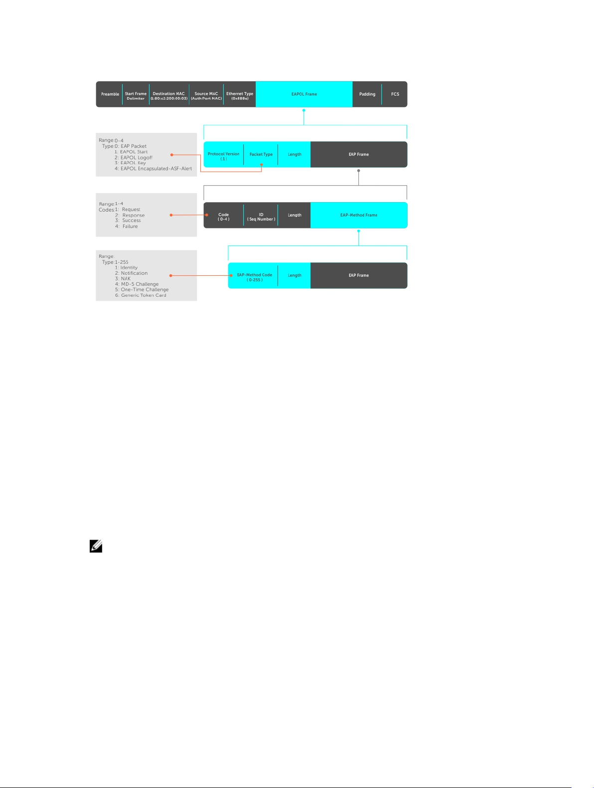
Figure 7. EAP Frames Encapsulated in Ethernet and RADUIS
The authentication process involves three devices:
• The device attempting to access the network is the supplicant. The supplicant is not allowed to
communicate on the network until the authenticator authorizes the port. It can only communicate
with the authenticator in response to 802.1X requests.
• The device with which the supplicant communicates is the authenticator. The authenticator is the
gate keeper of the network. It translates and forwards requests and responses between the
authentication server and the supplicant. The authenticator also changes the status of the port based
on the results of the authentication process. The Dell Networking switch is the authenticator.
• The authentication-server selects the authentication method, verifies the information the supplicant
provides, and grants it network access privileges.
Ports can be in one of two states:
• Ports are in an unauthorized state by default. In this state, non-802.1X traffic cannot be forwarded in
or out of the port.
• The authenticator changes the port state to authorized if the server can authenticate the supplicant.
In this state, network traffic can be forwarded normally.
NOTE: The Dell Networking switches place 802.1X-enabled ports in the unauthorized state by
default.
The Port-Authentication Process
The authentication process begins when the authenticator senses that a link status has changed from
down to up:
1. When the authenticator senses a link state change, it requests that the supplicant identify itself using
an EAP Identity Request frame.
2. The supplicant responds with its identity in an EAP Response Identity frame.
802.1X
99
Page 100
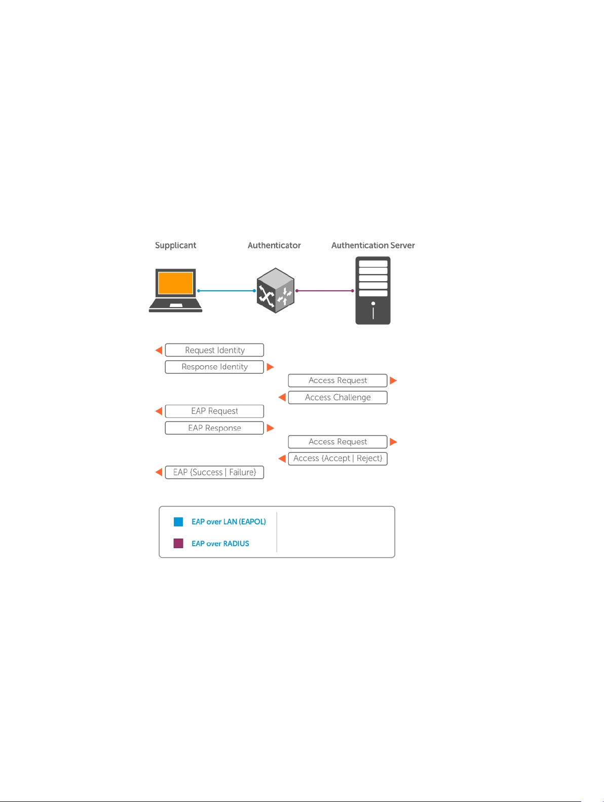
3. The authenticator decapsulates the EAP response from the EAPOL frame, encapsulates it in a
RADIUS Access-Request frame and forwards the frame to the authentication server.
4. The authentication server replies with an Access-Challenge frame. The Access-Challenge frame
requests that the supplicant prove that it is who it claims to be, using a specified method (an EAPMethod). The challenge is translated and forwarded to the supplicant by the authenticator.
5. The supplicant can negotiate the authentication method, but if it is acceptable, the supplicant
provides the Requested Challenge information in an EAP response, which is translated and
forwarded to the authentication server as another Access-Request frame.
6. If the identity information provided by the supplicant is valid, the authentication server sends an
Access-Accept frame in which network privileges are specified. The authenticator changes the port
state to authorized and forwards an EAP Success frame. If the identity information is invalid, the
server sends an Access-Reject frame. If the port state remains unauthorized, the authenticator
forwards an EAP Failure frame.
Figure 8. EAP Port-Authentication
100
802.1X
 Loading...