

Dell Force10 MXL Blade White Paper
Authors
Network Enabled Solutions Team
Jason Pearce, Manjesh Siddamurthy
Networking Enterprise Technologist
Kevin Horton
Deploying the Dell Force10 MXL into a
Cisco Nexus Network Environment
A guide with basic examples for deploying the Dell Force10 MXL
modular switch into the access layer of a Cisco Nexus network

Deploying the Dell Force10 MXL into a Cisco Nexus Network Environment
This document is for informational purposes only and may contain typographical errors and
technical inaccuracies. The content is provided as is, without express or implied warranties of any
kind.
© 2012 Dell Inc. All rights reserved. Dell and its affiliates cannot be responsible for errors or omissions
in typography or photography. Dell, the Dell logo, and PowerEdge are trademarks of Dell Inc. Intel and
Xeon are registered trademarks of Intel Corporation in the U.S. and other countries. Microsoft,
Windows, and Windows Server are either trademarks or registered trademarks of Microsoft Corporation
in the United States and/or other countries. Other trademarks and trade names may be used in this
document to refer to either the entities claiming the marks and names or their products. Dell disclaims
proprietary interest in the marks and names of others.
December 2012| Rev 1.1
2

Deploying the Dell Force10 MXL into a Cisco Nexus Network Environment
Contents
Introduction .............................................................................................................. 5
Content Overview ..................................................................................................... 6
Document Conventions ............................................................................................... 7
Device Introduction ................................................................................................... 8
Dell Force10 MXL Deployment ...................................................................................... 12
Initial Configuration ................................................................................................. 12
Access Port Downlink Configuration .............................................................................. 16
Trunk Port Downlink Configuration ............................................................................... 18
Link Aggregation Group Configuration ........................................................................... 20
Trunk Port Uplink Configuration with MLAG at Top of Rack ................................................. 21
Trunk Port Uplink Configuration with Per-VLAN Spanning Tree ............................................. 27
Spanning Tree Protocol Failover and Failback Observations .................................................. 31
Lab Environment ..................................................................................................... 31
Nexus MSTP and MXL MSTP Observations ........................................................................ 32
Nexus MSTP and MXL MSTP – Remainder of Test Observations .............................................. 37
Nexus MSTP and MXL MSTP – Greater than 64 Instances ...................................................... 38
Nexus Rapid PVST+ and MXL PVST Observations ............................................................... 38
Nexus Rapid PVST+ and MXL PVST – Remainder of Test Observations ...................................... 42
Summary – Spanning Tree Observations ......................................................................... 42
Appendices ............................................................................................................. 43
Appendix A: Referenced Network Topology and Device Configurations ................................... 43
Appendix B: Basic Terminology ................................................................................... 54
3

Deploying the Dell Force10 MXL into a Cisco Nexus Network Environment
Figures
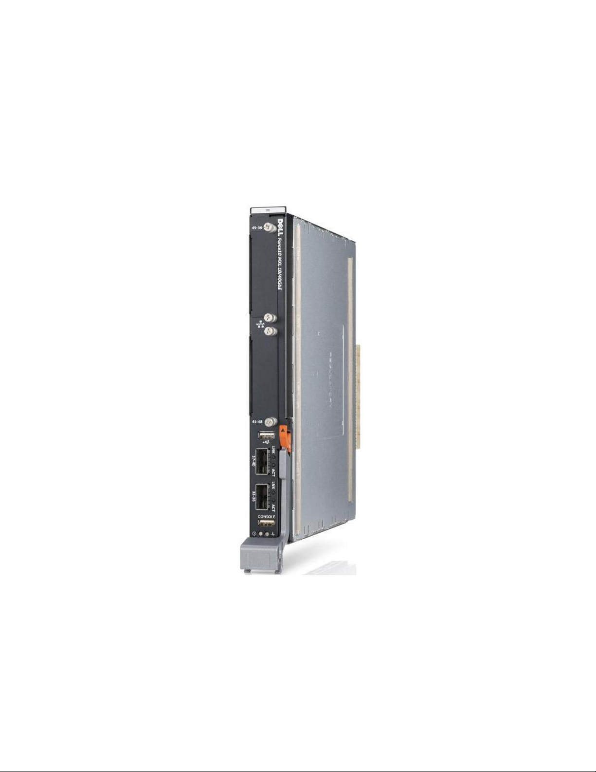
Figure 1. Dell Force10 MXL Switch .................................................................................. 5
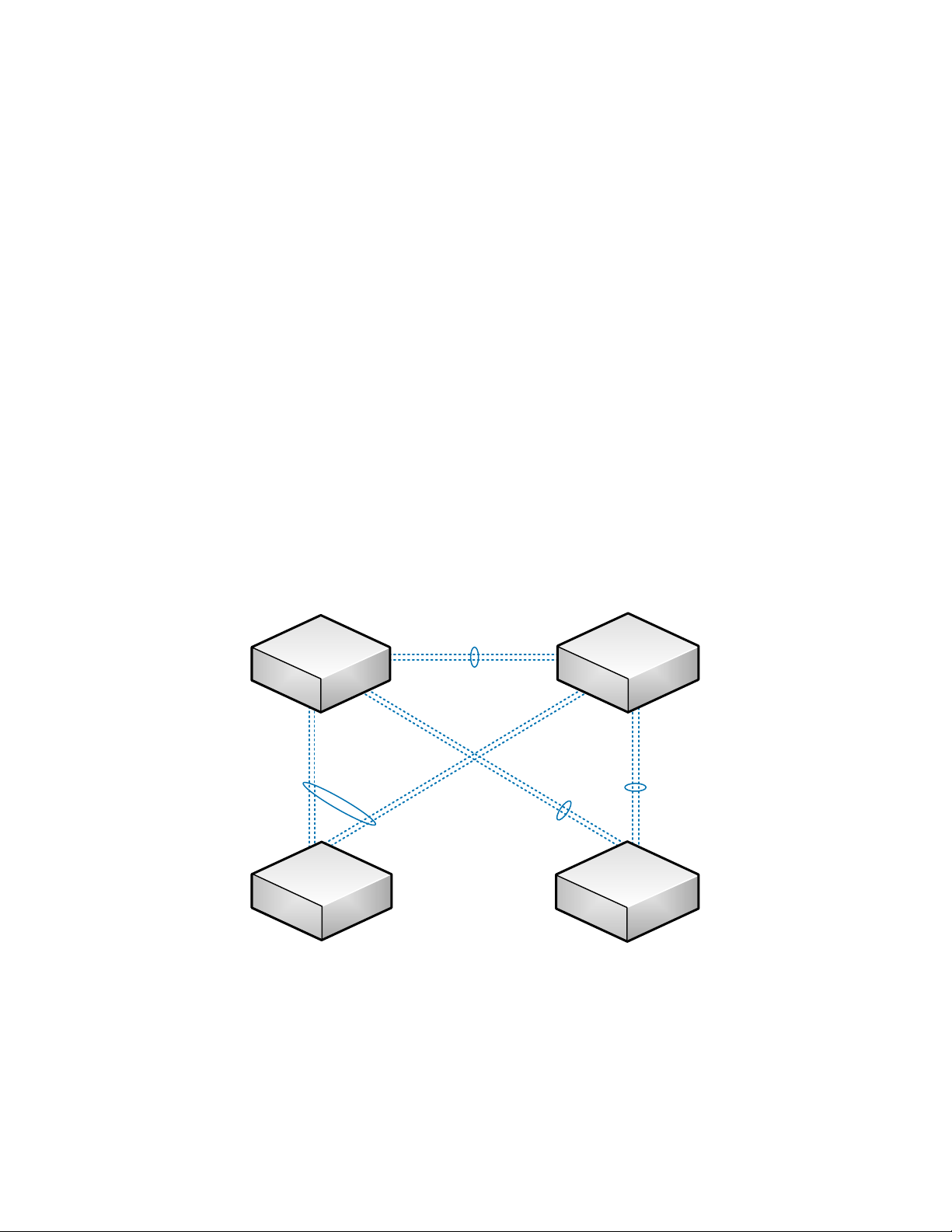
Figure 2. Example Network Topology .............................................................................. 7
Figure 3. MXL External Interfaces ................................................................................... 8
Figure 4. FlexIO 40GbE QSFP+ Module .............................................................................. 9
Figure 5. FlexIO 10GbE SFP+ Module ............................................................................... 9
Figure 6. FlexIO 10GBASE-T Module ................................................................................ 9
Figure 1. Topology Diagram: Top of Rack Nexus 5K using vPC ............................................... 21
Figure 2. Topology Diagram: Top of Rack Nexus 5K using PVST+ ............................................ 27
Figure 3. Topology Diagram: STP Interoperability Observations Lab ....................................... 31
Figure 4. Topology Diagram: Detailed, Full Example Network ............................................... 43
Tables
Table 1. Force10 MXL External Ethernet Interface Numbering ............................................. 10
Table 2. Results – Spanning Tree Observations ................................................................ 42
Table 3. Devices and Firmware Versions Used in this Document ........................................... 44
4
Deploying the Dell Force10 MXL into a Cisco Nexus Network Environment
Introduction
This document is an easy-to-use guide of recommended basic deployment practices for the Dell
Force10 MXL in the access layer of a Cisco Nexus network environment. The Dell Force 10 MXL—an I/O
module for the Dell PowerEdge M1000e chassis—is a 10 and 40 gigabit Ethernet multilayer switch
targeted at deployment in data center networks. The MXL provides 32 10GbE internal ports to server
blades in an M1000e modular chassis and has multiple 10 and 40GbE external uplink and stacking
options allowing it to serve well in many applications and environments.
Dell Force10 MXL Switch Figure 1.
The Dell Force10 MXL 10/40GbE switch brings a new level of connectivity and value to the blade server
network switch environment. With 32 1/10GbE server facing ports, any transition from previous
architectures will be a huge step forward. The 32 server facing ports provide connectivity on any of the
available fabric slots (A, B, or C) for the M-Series blade servers with 1GbE or 10GbE KR-based network
card capability. The switch offers 1/10/40GbE connectivity on the uplinks to interface with a top of
rack switch, directly to a core switch, or directly to an iSCSI storage solution.
The MXL switch is an industry first, 40GbE capable, modular, and stackable blade switch for the
PowerEdge M1000e chassis.
5

Deploying the Dell Force10 MXL into a Cisco Nexus Network Environment
Content Overview
This document is broken up topically to allow the steps and concepts of MXL switch deployment to be
addressed separately in a simple manner as detailed in Document Conventions. An introduction to the
Force10 MXL hardware and its connectivity and management options is presented in Device
Introduction. Once familiarized with the MXL switch, the out-of-box experience is continued with the
first steps of MXL deployment as presented in Initial Configuration.
Link configuration is split into coverage of downlink configuration options (on the MXL, downlinks are
generally its internal ports which connect to the server blades in a deployed M1000e chassis),
configuration of a link aggregation group (LAG)—a set of ports configured to pass traffic together and
behave as one link, and coverage of uplink configuration options (on the MXL these are generally its
external ports, which connect to administratively designated ports on top-of-rack or end-of-row
switches.
Downlink configuration for the MXL is covered for the two most common use cases: for VLAN unaware
servers see Access Port Downlink Configuration and for VLAN aware servers see Trunk Port Downlink
Configuration.
LAG configuration is then covered in Link Aggregation Group Configuration. While LAGs are sometimes
configured on downlinks (dependent on application demands) they are recommended to use with
uplinks.
Uplink configuration for the MXL will generally be done in one of two ways in a Cisco Nexus network
environment: running PVST with discreet LAGs connected to separate top-of-rack switches as covered
in Trunk Port Uplink Configuration with Per-VLAN Spanning Tree and running PVST with a single LAG
connected across two top-of-rack switches that are using a Multi-chassis LAG as covered in Trunk Port
Uplink Configuration with MLAG at Top of Rack (this uses the Cisco Nexus vPC feature).
To present the above configuration options as clearly as possible in this document, they have been
integrated into a single example network. The full details of the example network, including overall
topology and the complete configurations of the participating devices, are presented in Appendix A.
A glossary of applicable networking terms and concepts can be found in Appendix B. The definitions
listed there are used throughout this document; so as unfamiliar terms are encountered in this
document, refer to Appendix B for their definitions.
Additional materials referenced in this document and useful for configuration that is more advanced or
specific than what this document covers are detailed in Appendix C.
6
Deploying the Dell Force10 MXL into a Cisco Nexus Network Environment
po
20
(
vpc
1
)
po20 (vpc1)
Nexus
N5K1
Nexus
N5K2
Force10
MXL1
Force10
MXL2
po10—po10
vPC link
po40—po40
po
30
—
po
30
po
20
—
vpc
1
Document Conventions
This document is intended as a quick reference guide for use during basic deployment of a Force10 MXL
switch. As such, many details, configuration options, and specific features of the MXL are left out of
this document.
Example CLI Notation:
FTOS#configure
FTOS(conf)#hostname MXL1
MXL1(conf)#exit
MXL1#
As shown above, CLI examples are listed inside indented text blocks, use a monospace font, the user
input is emboldened, and the portions of the commands that will likely need to be adjusted for local
use are emboldened and italicized. Also note that each CLI example starts in privileged execution
mode and where needed starts and ends with commands to move between modes. Following this
practice each time is not required when entering multiple examples together (commands issued in the
same mode can generally be strung together). But, it is presented in this manner to ease following
individual examples in the document.
Example Network Topology:
Example Network Topology Figure 2.
As shown in the figure above, the network topology diagrams in this document are kept as simple as
possible to communicate the need-to-know information for the topic on hand. Figure 2 above shows the
example network that is explored in this document. While the example network topology does not
mirror a production environment, individual parts of it do and the example topology does illustrate
those parts more clearly. A more detailed topology diagram of this example network can be found in
Appendix A.
7
Deploying the Dell Force10 MXL into a Cisco Nexus Network Environment
IO Bay 2
IO Bay 1
Fixed QSFP+ Ports
Device Introduction
The Dell Force10 MXL is an I/O Module for the M1000e modular server chassis that is a line-speed,
multilayer, 10 and 40Gb Ethernet switch that provides 32 internal 10GbE links—enabling full
connectivity to M420 quarter-height server blades—and flexible 10 and 40Gb Ethernet options for
external connectivity. With as much as 240 Gigabits of full-duplex external connectivity, it offers a
favorable 1.33:1 over-subscription ratio of internal to external connectivity. With spanning-tree options
of RSTP, MSTP, and PVST it can be natively integrated into most layer-2 network environments and
optionally participate at layer-3 environments using OSPF or static routing. The MXL also offers DataCenter Bridging features enabling it to act as an FCoE transit switch (FIP snooping bridge). This
document however only covers basic layer-2 deployment.
External Interfaces—Connectivity, Cabling, and Port Numbering
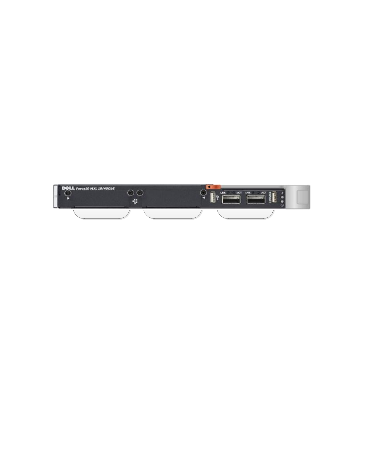
MXL External Interfaces Figure 3.
IO Bays 2 and 1 can each use one of the FlexIO modules detailed below. The fixed QSFP+ 40Gb
Ethernet ports can be connected using Dell Force10 QSFP+ transceivers or Dell Force10 twinax cabling.
Additionally there are special breakout fiber and twinax cables that allow each 40GbE port to instead
be split into four 10GbE links that will connect with compatible 10GbE fiber transceivers or SFP+ ports
respectively.
Between IO Bay 1 and the fixed QSFP+ ports is a USB type-A port that allows directly connecting a USB
storage device to the MXL for copying files directly to and from the switch. Between the fixed QSFP+
ports and the MXL’s latch hinge are the MXL’s status indicator LEDs and a serial console interface that
uses a physical USB type-A port—a required serial console cable is provided with each Force10 MXL
switch. If the serial console cable is unavailable, the console may also be accessed via the M1000e CMC
CLI “connect” command. Access to the serial console (either via the provided cable or the CMC) is
required for manual out-of-box deployment of the MXL switch. See Management Connectivity for
further details.
8
Deploying the Dell Force10 MXL into a Cisco Nexus Network Environment
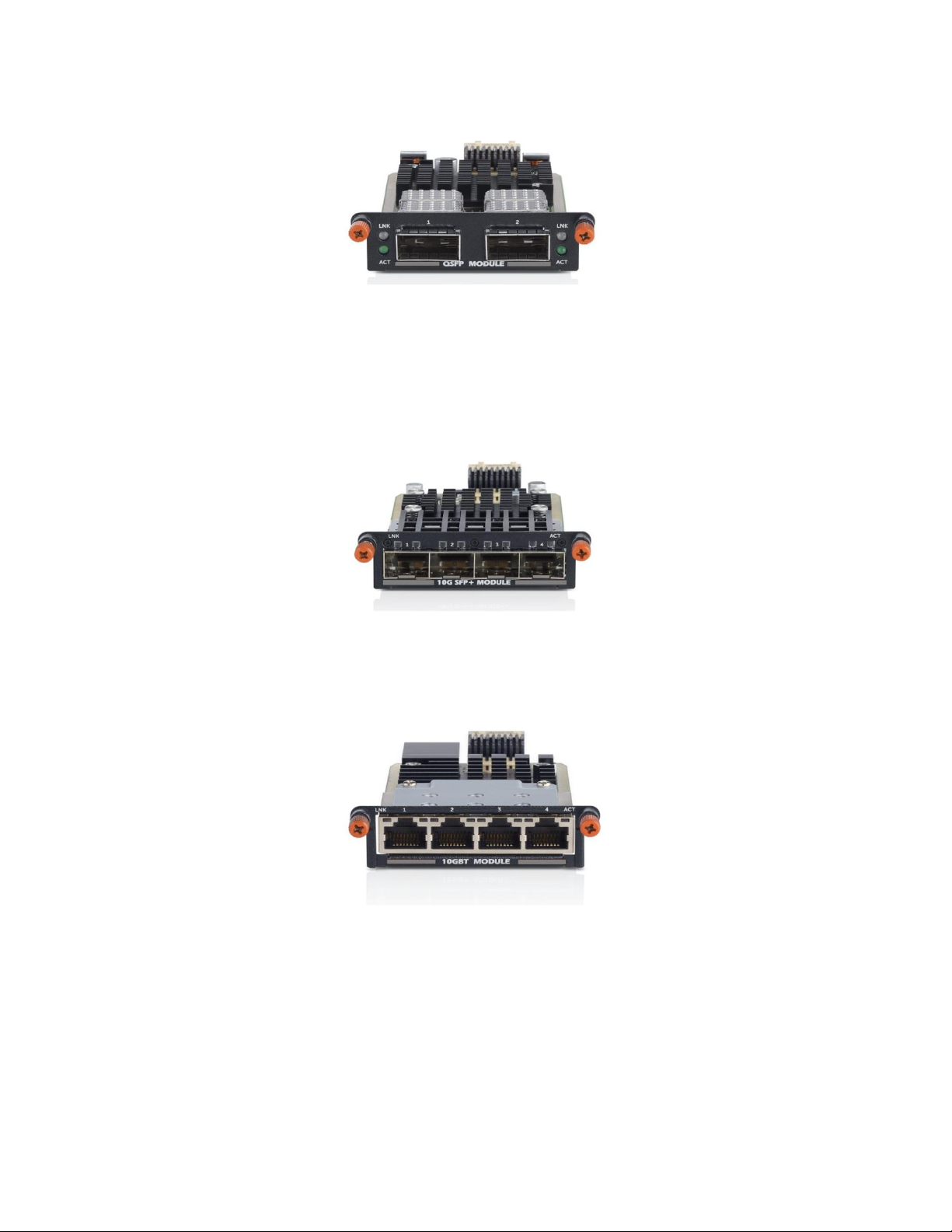
Figure 4.
The FlexIO 40GbE QSFP+ module provides two 40Gb Ethernet ports that can be connected using Dell
Force10 QSFP+ transceivers or Dell Force10 twinax cabling. Additionally Dell offers breakout fiber and
twinax cables that enable each 40GbE port to be split into four 10GbE links that will connect with
compatible 10GbE fiber transceivers or SFP+ ports . This industry leading QSFP+ module provides the
highest throughput available for each MXL FlexIO bay.
FlexIO 40GbE QSFP+ Module
FlexIO 10GbE SFP+ Module Figure 5.
The FlexIO 10GbE SFP+ module provides four 10Gb Ethernet ports that can be connected using Dell
Force10 SFP+ transceivers or Dell Force10 twinax cabling.
FlexIO 10GBASE-T Module Figure 6.
The FlexIO 10GBASE-T module provides four 10Gb Ethernet RJ45 ports that can be connected to other
10GBASE-T devices using standard Cat6A cabling.
9
Deploying the Dell Force10 MXL into a Cisco Nexus Network Environment
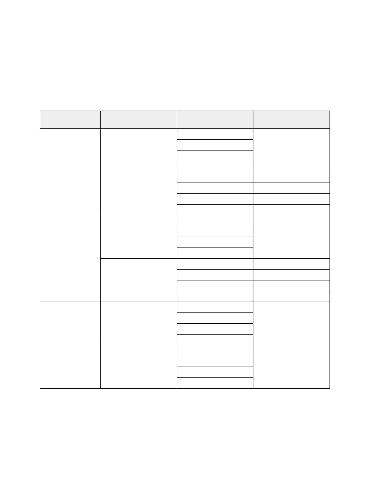
Module Type
Link Speed
QSFP+
40GbE
QSFP+ (breakout cables)
10GbE
SFP+ / 10GBASE-T
10GbE
IO Bay 2
53
56
n/a
55
54
53
49
52
52
51
51
50
50
49
49
IO Bay 1
45
48
n/a
47
46
45
41
44
44
43
43
42
42
41
41
Fixed QSFP+ Ports
37
40
n/a
39
38
37
33
36
35
34
33
Due to the availability of FlexIO modules with varying port and link count, the external interface
numbering on the MXL can be difficult to understand. Table 1 details the external interface numbering
in various modular configurations of the MXL switch. This numbering follows the potential10GbE links
skipping numbers where available link count is less than the potential. Both the Ethernet interfaces
and IO Bays are numbered from bottom to top when the MXL switch is installed in an M1000e modular
chassis.
Force10 MXL External Ethernet Interface Numbering Table 1.
10

Deploying the Dell Force10 MXL into a Cisco Nexus Network Environment
Management Connectivity
The MXL switch provides a number of methods for connectivity to its management command-line
interface (CLI).
Out-of-band console connectivity is available via serial on a physical USB type-A port on the face of the
switch when used with the provided cable that is shipped with each MXL (see the previous section—
External Interfaces—for help identifying the port). Serial terminal settings to access the console are set
to 9600bps, no flow control, 8 character bits and 1 stop bit.
Out-of-band console access is also available via the CMC (Chassis Management Controller) “connect”
command. A simple example is shown here using ssh to attach to the CMC console. For more
information about accessing and using the CMC console, see the CMC User Guide.
~ % ssh root@172.25.188.40
root@172.25.188.40’s password:
Welcome to the CMC firmware version 4
$ connect switch-b1
connect: acquiring remote port.
Connected to remote port.
Escape character is '^\'.
MXL1>
Out-of-band network connectivity is provided through the M1000e CMC’s Ethernet connection and is
configurable on the MXL’s CLI as the “managementethernet” interface. With the management Ethernet
interface configured, the telnet or SSH services can be enabled to provide remote access to the
command-line interface of the MXL. Example commands for configuring the management Ethernet
interface and the telnet and SSH services of the MXL can be found in the Initial Configuration section of
this document.
11

Deploying the Dell Force10 MXL into a Cisco Nexus Network Environment
Dell Force10 MXL Deployment
Initial Configuration
This section provides a rapid introduction to some common MXL initial deployment tasks. For more
detailed information on deploying the MXL see the Force10 MXL User Guide. The examples that are
shown here start in privileged execution mode. On the serial console, privileged execution mode can
be reached by using the “enable” command.
Configure the MXL Host Name
The configured hostname appears in the management prompt of the CLI and helps to quickly identify
which device is being managed.
FTOS#configure
FTOS(conf)#hostname MXL1
MXL1(conf)#exit
MXL1#
Throughout this document two MXL switches are configured that have the host names MXL1 and MXL2.
Their full configurations can be found in Appendix A.
Configure an IP Address and Default Gateway on the MXL Out-of-Band Management Interface
The out-of-band management Ethernet interface provides connectivity through the M1000e Chassis
Management Controller. Only management traffic is sent or received on this interface.
MXL1#configure
MXL1(conf)#interface managementethernet 0/0
MXL1(conf-if-ma-0/0)#ip address 192.0.2.10/24
Proceed with Static IP [confirm yes/no]: yes
MXL1(conf-if-ma-0/0)#no shutdown
MXL1(conf-if-ma-0/0)#exit
MXL1(conf)#management route 0.0.0.0/0 192.0.2.1
MXL1(conf)#exit
MXL1#
The IP address of the management Ethernet interface can also be configured by the M1000e Chassis
Management Controller. For further details see the CMC User Guide.
Add an Admin’s Username and Enable Password to the MXL configuration
In order to control access to the administration of the MXL, set username(s) and enable passwords.
MXL1#configure
MXL1(conf)#username NewUserName password NewUserPassword privilege 15
MXL1(conf)#no username root
12

Deploying the Dell Force10 MXL into a Cisco Nexus Network Environment
MXL1(conf)#enable password NewEnablePassword
MXL1(conf)#exit
MXL1#
Configuring a username allows an individual to authenticate and is required for remote management.
The root user (with password calvin) is automatically configured on the MXL during its first boot to
enable rapid remote management during deployment. It is highly recommended to remove the default
root user once local user accounts are configured.
Setting the enable password keeps unprivileged users and anyone with serial console access from
changing the configuration of the switch. A user with privilege set to 15 runs in privileged execution
mode and is not required to enter the enable password to manage the switch.
For a more secure remote management service it is recommended to use SSH.
Enable the SSH service on the MXL
SSH provides secure remote management connectivity to the MXL’s CLI.
MXL1#configure
MXL1(conf)#ip ssh server enable
MXL1(conf)#exit
MXL1#
SSH requires keys in order to work properly.
You can determine if either an RSA or RSA1 key exists already by entering:
MXL1#
MXL1#show crypto key mypubkey rsa
ssh-rsa AAAAB3NzaC1yc2EAAAABIwAAAIEA7grssrAVe5qZM2hDGlxDBAolYCVFIWpeffW
BK1Ac1lvVsIKm+BjICf/bS16qwRuimdznFxNdUmru6hcbLNSe2m4c7mtdVI5D9gC6DYnHKH
OG9sqTkF46o2TQ5QsYV4cBZWvY69XF14XFzbAJBAJCcnZnD953pKm5VnMdzEf7YzE=
MXL1#
Or to check for existence of RSA1 Key:
MXL1#
MXL1#show crypto key mypubkey rsa1
ssh-rsa AAAAB3NzaC1yc2EAAAABIwAAAIEA7grssrAVe5qZM2hDGlxDBAolYCVFIWpeffW
BK1Ac1lvVsIKm+BjICf/bS16qwRuimdznFxNdUmru6hcbLNSe2m4c7mtdVI5D9gC6DYnHKH
OG9sqTkF46o2TQ5QsYV4cBZWvY69XF14XFzbAJBAJCcnZnD953pKm5VnMdzEf7YzE=
MXL1#
If no keys exist – or you wish to create new keys – then the following commands would be used with
either RSA or RSA1 as the keyword in the command.
MXL1#configure
MXL1(conf)#crypto key gen rsa
Enter key size <1024-2048>. Default<1024>:
Generating SSHv2 RSA key.
!!!!!!!!!!!!!!!!!!!!!!!!!!!!!!!!!!!!!!!!!!!!!!!!!!!!!!!!!!!!!!!!!!!!!!!
!!!!!!!!!!!!!!!!!!!!!!
13

Deploying the Dell Force10 MXL into a Cisco Nexus Network Environment
MXL1(conf)#exit
MXL1#
For additional information regarding SSH please refer to the MXL User Guide.
After configuring SSH and having confirmed the configuration is correct by logging in using SSH, it is
recommended to disable Telnet for security reasons.
Disable the Telnet Service on the MXL
Telnet provides simple remote connectivity to the MXL’s CLI and is enabled by default. It is however
not as secure as SSH and is not allowed in many environments due to security concerns. The following
example shows how to disable the telnet service on the MXL.
MXL1#configure
MXL1(conf)#no ip telnet server enable
MXL1(conf)#exit
MXL1#
Determine if Spanning Tree is already enabled
The goal is to run Per-VLAN Spanning Tree (PVST) but before PVST is configured, other spanning tree
implementations must not already be enabled. In this example, RSTP is already running so it must be
disabled before PVST can be enabled.
MXL1#show run | grep spanning
protocol spanning-tree rstp
MXL1#configure
MXL1#protocol spanning-tree rstp
MXL1(conf-rstp)#disable
MXL1(conf-rstp)#exit
MXL1(conf)#no protocol spanning-tree rstp
MXL1(conf)#exit
MXL1#
Enable Per-VLAN Spanning Tree on the MXL
Per-VLAN Spanning Tree (PVST) is an implementation of the spanning-tree protocol where a separate
spanning tree is run inside of each VLAN. This allows network administrators to configure each VLAN
with optimal root placement and active paths across a network topology. Most Cisco Nexus network
environments run PVST and this document shows how to configure Dell Force10 MXL switches to
operate natively in these environments by also running PVST.
MXL1#configure
MXL1(conf)#protocol spanning-tree pvst
MXL1(conf-pvst)#no disable
MXL1(conf-pvst)#exit
MXL1(conf)#exit
MXL1#
14

Deploying the Dell Force10 MXL into a Cisco Nexus Network Environment
Split an MXL 40Gb Ethernet Interface into Four 10Gb Ethernet Links
The external QSFP+ 40Gb Ethernet ports can be configured as four separate 10Gb Ethernet links.
Physical connectivity is enabled by an optical split fiber cable or a split twinax cable. When a 40GbE
port is run in quad mode, it provides four 10Gb Ethernet interfaces that number sequentially starting
with the port number of the 40GbE interface. In the following example this makes four 10GbE links
numbered 33, 34, 35, and 36 from the single 40GbE port numbered 33.
MXL1#configure
MXL1(conf)#stack-unit 0 port 33 portmode quad
Please save and reload for the changes to take effect.
MXL1(conf)#exit
MXL1#copy running-config startup-config
File with same name already exist.
Proceed to copy the file [confirm yes/no]: yes
!
5678 bytes successfully copied
MXL1#reload
Proceed with reload [confirm yes/no]: yes
Note, as shown in the above example, splitting a 40GbE port into four 10GbE links requires saving the
configuration and reloading the MXL to take effect.
Save the Current MXL Configuration Settings
Always remember to save your settings so that they are not lost in case the switch is restarted.
MXL1#copy running-config startup-config
File with same name already exist.
Proceed to copy the file [confirm yes/no]: yes
!
5678 bytes successfully copied
MXL1#
15

Deploying the Dell Force10 MXL into a Cisco Nexus Network Environment
Access Port Downlink Configuration
Server’s network interfaces’ default configuration works with a single subnet available on the link and
no VLAN tagging. To provide connectivity to this type of server interface, the matching switch
interface that it connects to should be configured as an access port in the server’s designated VLAN.
Similar to the described server interface, an access port participates in only one VLAN and does not
insert tags into the Ethernet frames on its link. To deploy an access port on an MXL running PVST follow
these steps.
Configure a Downlink as an Access Port
MXL1#configure
MXL1(conf)#interface tengigabitethernet 0/1
MXL1(conf-if-te-0/1)#switchport
MXL1(conf-if-te-0/1)#spanning-tree pvst edge-port
MXL1(conf-if-te-0/1)#exit
MXL1(conf)#exit
MXL1#
The “switchport” setting enables a switch’s Ethernet interface to participate in VLANs (prior to this
command being run Force10 switch interfaces default to not forwarding traffic at all).
It is recommended that the “spanning-tree pvst edge-port” command should only be run on ports that
will connect to servers or other end nodes and not on ports that will connect to other switches. This
command designates a port as an expected edge of the spanning tree (only switches participate in
spanning tree) and enables it to begin forwarding traffic as soon as it’s connected (many seconds
before the spanning-tree protocol would otherwise clear it for active use).
With the switchport feature enabled, the Ethernet interface is now ready for a VLAN to be configured
for it.
Configure a VLAN for an Access Port Interface
MXL1#configure
MXL1(conf)#interface vlan 11
MXL1(conf-if-vl-11)#untagged tengigabitethernet 0/1
MXL1(conf-if-vl-11)#no shutdown
MXL1(conf-if-vl-11)#exit
MXL1(conf)#exit
MXL1#
As discussed above, an access port only participates in one VLAN at a time so if another VLAN were
configured for this same port, it would remove the port from the first VLAN. For server interfaces that
need access to multiple VLANs, see Trunk Port Downlink Configuration.
Now that a VLAN is configured for the access port, it is ready to be enabled. (To keep server network
traffic where it is expected to be on the network, it is important to enable downlinks only after they
are correctly configured.)
Enable the Configured Ethernet Interface
MXL1#configure
MXL1(conf)#interface tengigabitethernet 0/1
MXL1(conf-if-te-1)#no shutdown
16

Deploying the Dell Force10 MXL into a Cisco Nexus Network Environment
MXL1(conf-if-te-1)#exit
MXL1(conf)#exit
MXL1#
For administrative convenience the above steps can be applied to a range of switch interfaces during
configuration. In the following example, the downlinks of MXL1 in the example network are all
configured as access ports with interfaces 1-8 on VLAN 11, interfaces 9-24 on VLAN 12, and interfaces
25-32 on VLAN 13.
Access Port CLI Example Using Interface Range
MXL1#configure
MXL1(conf)#interface range tengigabitethernet 0/1 - 32
MXL1(conf-if-range-te-0/1-32)#switchport
MXL1(conf-if-range-te-0/1-32)#spanning-tree pvst edge-port
MXL1(conf-if-range-te-0/1-32)#exit
MXL1(conf)#interface Vlan 11
MXL1(conf-if-vl-11)#untagged tengigabitethernet 0/1-8
MXL1(conf-if-vl-11)#no shutdown
MXL1(conf-if-vl-11)#exit
MXL1(conf)#interface Vlan 12
MXL1(conf-if-vl-12)#untagged tengigabitethernet 0/9-24
MXL1(conf-if-vl-12)#no shutdown
MXL1(conf-if-vl-12)#exit
MXL1(conf)#interface Vlan 13
MXL1(conf-if-vl-13)#untagged tengigabitethernet 0/25-32
MXL1(conf-if-vl-13)#no shutdown
MXL1(conf-if-vl-13)#exit
MXL1(conf)#interface range tengigabitethernet 0/1 - 32
MXL1(conf-if-range-te-0/1-32)#no shutdown
MXL1(conf-if-range-te-0/1-32)#exit
MXL1(conf)#exit
MXL1#
To see how the above commands affect the MXL’s running configuration, review the example MXL1
running configuration in Appendix A.
17

Deploying the Dell Force10 MXL into a Cisco Nexus Network Environment
Trunk Port Downlink Configuration
Trunk ports can participate in multiple VLANs over one Ethernet interface and are often used for
connection to virtualization hosts and other VLAN aware applications. To keep the traffic of the
different VLANs from mixing, a numbered tag is inserted in each Ethernet frame (with the optional
exception of the interface’s “native” VLAN). To deploy a trunk port on an MXL running PVST follow
these four steps.
Configure a Downlink as a Trunk Port
MXL2#configure
MXL2(conf)#interface tengigabitethernet 0/1
MXL2(conf-if-te-0/1)#portmode hybrid
MXL2(conf-if-te-0/1)#switchport
MXL2(conf-if-te-0/1)#spanning-tree pvst edge-port
MXL2(conf-if-te-0/1)#exit
MXL2(conf)#exit
MXL2#
The “switchport” setting enables a switch’s Ethernet interface to participate in VLANs. A switchport
enabled interface is referred to as a layer-2 interface. (Note: If the Ethernet interface had previously
been configured as a layer-3 interface—which is one with an IP address directly configured on it—than
the “no ip address” command would need to be run on the interface before the switchport feature
could be enabled.)
The “portmode hybrid” command allows an Ethernet interface to carry both multiple tagged VLANs and
a single untagged (also called a native) VLAN. If a given port is only expected to carry tagged VLANs or
a single untagged VLAN, the “portmode hybrid” command may be omitted from its configuration.
The “spanning-tree pvst edge-port” command should only be run on ports that will connect to servers
or other end nodes and never on ports that will connect to other switches. This command designates a
port as an expected edge of the spanning tree (only switches participate in spanning tree) and enables
it to begin forwarding traffic as soon as it’s link is active (many seconds before the spanning-tree
protocol would otherwise allow it to forward traffic).
With the switchport feature enabled, the Ethernet interface is now ready for one or more tagged
VLANs to be configured for it.
Configure Tagged VLANs for a Trunk Port Interface
MXL2#configure
MXL2(conf)#interface vlan 11
MXL2(conf-if-vl-11)#tagged tengigabitethernet 0/1
MXL2(conf-if-vl-11)#no shutdown
MXL2(conf-if-vl-11)#exit
MXL2(conf)#interface vlan 12
MXL2(conf-if-vl-12)#tagged tengigabitethernet 0/1
MXL2(conf-if-vl-12)#no shutdown
MXL2(conf-if-vl-12)#exit
MXL2(conf)#exit
MXL2#
18
 Loading...