

Page 1

Dell Force10
E300, E600i, and E1200i
Systems
Quick Start Guide
Regulatory Model: E300/E600i
TeraScale/E600i ExaScale/
E1200i TeraScale/E1200i
ExaScale
Page 2

Page 3

Dell Force10
E300, E600i, and E1200i
Systems
Quick Start Guide
Regulatory Model: E300/E600i
TeraScale/E600i ExaScale/
E1200i TeraScale/E1200i
ExaScale
Page 4

Notes, Cautions, and Warnings
NOTE: A NOTE indicates important information that helps you make better use
of your computer.
CAUTION: A CAUTION indicates potential damage to hardware or loss of
data if instructions are not followed.
WARNING: A WARNING indicates a potential for property damage,
personal injury, or death.
If you purchased a Dell n Series computer, any references in this publication to
Microsoft
Windows operating sys tems are not applicable.
____________________
Information in this publication is subject to change without notice.
© 2011 Dell Inc.Allrightsreserved.
Reproduction of these materials in any manner whatsoever without the written permission of Dell Inc.
is strictly forbidden.
Trademarks used in this text: Dell™, the DELL logo, Dell Precision™, OptiPlex™, Latitude™,
PowerEdge™, PowerVault™, PowerConnect™, OpenManage™, EqualLogic™, KACE™,
FlexAddress™ and Vostro™ are trademarks of Dell Inc. Intel
®
Celeron
registered trademark and AMD Opteron™, AMD Phenom™, and AMD Sempron™ are trademarks
of Advanced Micro Devices, Inc. Microsoft
Windows V ista
States and/or other countries. Red Hat Enterprise Linux
trademarks of Red Hat, Inc. in the United States and/or other countries. Novell
trademark and SUSE ™ is a trademark of Novell Inc. in the United States and other countries. Oracle
is a registered trademark of Oracle Corporation and/or its affiliates. Citrix
XenMotion
and/or other countries. VMware
trademarks or trademarks of VMWare, Inc. in the United States or other countries.
Other trademarks and trade names may be used in this publication to refer to either the entities claiming
the marks and names or their products. Dell Inc. disclaims any proprietary interest in trademarks and
trade names other than its own.
Regulatory Model: E300/E600i TeraScale/E600i ExaScale/E1200i TeraScale/E1200i ExaScale
2011 - 9 P/N 08VJV0 Rev. A00
are registered trademarks of Intel Corporation in the U.S. and other countries. AMD® is a
®
®
are either trademarks or registered trademarks of Microsoft Corporation in the United
®
are either registered trademarks or trademarks of Citrix Systems, Inc. in the United States
®
, Virtual SM P®, vMotion®, vCenter®, and vSphere® are registered
, Windows®, Windows Server®, MS-DOS® and
®
, Pentium®, Xeon®, Core™ and
®
and Enterprise Linux® are registered
®
is a registered
®
, Xen®, XenServer® and
®
Page 5

About this Guide
This document is intended as a Quick Start Guide to get new systems up and
running and ready for configuration. For complete installation and configuration
information, refer to the following documents:
Documentation E300 E600i E1200i
Hardware
installation and
power-up
instructions
Software
configuration
Command line
interface
Latest updates FTOS Release Notes
Installing and
Maintaining the
E300 System
FTOS Configuration
Guide
FTOS Command
Line Reference
Guide
E600i System
Installation Guide
E600i TeraScale
Installation Guide
FTOS Configuration
Guide
FTOS Configuration
Guide for ExaScale
FTOS Command
Line Reference
Guide
FTOS Command
Line Reference
Guide for ExaScale
for the E-Series
TeraScale
FTOS Release Notes
for the E-Series
ExaScale
E1200i ExaScale
Installation Guide
Installing and
Maintaining the
E1200i System
FTOS Configuration
Guide
FTOS Configuration
Guide for ExaScale
FTOS Command
Line Reference
Guide
FTOS Command
Line Reference
Guide for ExaScale
FTOS Release Notes
for the E-Series
TeraScale
FTOS Release Notes
for the E-Series
ExaScale
About this Guide 3
Page 6

4 About this Guide
Page 7
1
Installing the Hardware
This guide assumes all site preparation has been performed before installing the
chassis.
Installing the Chassis
To install an E-Series chassis, Dell Force10 recommends that you complete the
installation procedures in the order presented below.
NOTE: Unless stated otherwise, the installation instructions below apply to all of
the E-Series chassis.
Always handle the system and its components with care. Avoid dropping the
switch or its field replaceable units.
CAUTION: The E-Series systems are packaged in one or two separate
containers. Use an equipment lift or pallet jack to lift or install the chassis.
Lifting the system by its shelves will cause damage to the chassis.
NOTE: If you are installing the chassis without using an equipment lift or pallet
jack, remove all AC power supplies, the fan tray , line cards, RPMs and SFMs from
the chassis prior to lifting it.
CAUTION: Always wear an ESD-preventive wrist or heel ground strap when
handling the chassis and its components. As with all electrical devices of this
type, take all necessary safety precautions to prevent injury when installing
this system. Electrostatic discharge (ESD) damage can occur if components
are mishandled.
Installing the Equipment Rack Shelf Bar
The equipment rack shelf bar must be installed first for all of the E-Series
chassis.
Step Task
1 Determine the chassis mounting location in the equipment rack.
2 Orient the bar with the arrows pointing upward. The smooth side of the
bar should face outward.
Installing the Hardware 5
Page 8
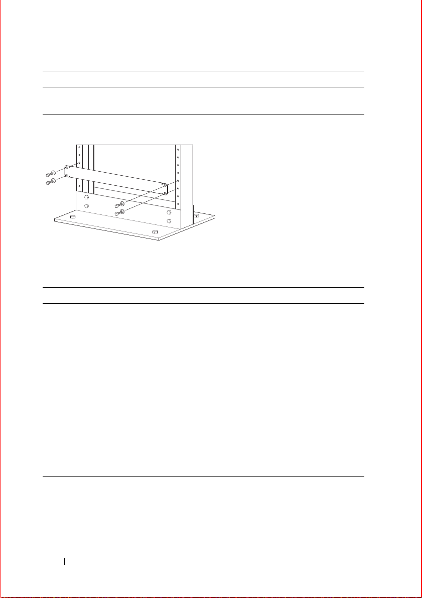
Step Task
3 Attach the bar to the equipment rack brackets using the mounting screws
provided by the rack manufacturer.
Installing the Chassis in a Two-Post Rack
Step Task
1 If you are center or rear mounting the chassis in a 19-inch rack, make
sure that the mounting brackets are properly positioned.
If your are mounting the chassis in a 23-inch rack, install the 23-inch
adapters.
2 Using a hand cart, pallet jack, or forklift, align the rack-mount holes
with the equipment rack holes, situating the chassis on top of the
equipment rack shelf bar.
3 Insert rack mounting screws in the holes that are not obscured by the
front shipping cover. Tighten the screws.
4 Loosen and remove the screws attaching the front shipping cover.
Remove the cover.
5 Insert the remaining rack mounting screws and tighten to secure the
chassis in the rack.
6 Installing the Hardware
Page 9
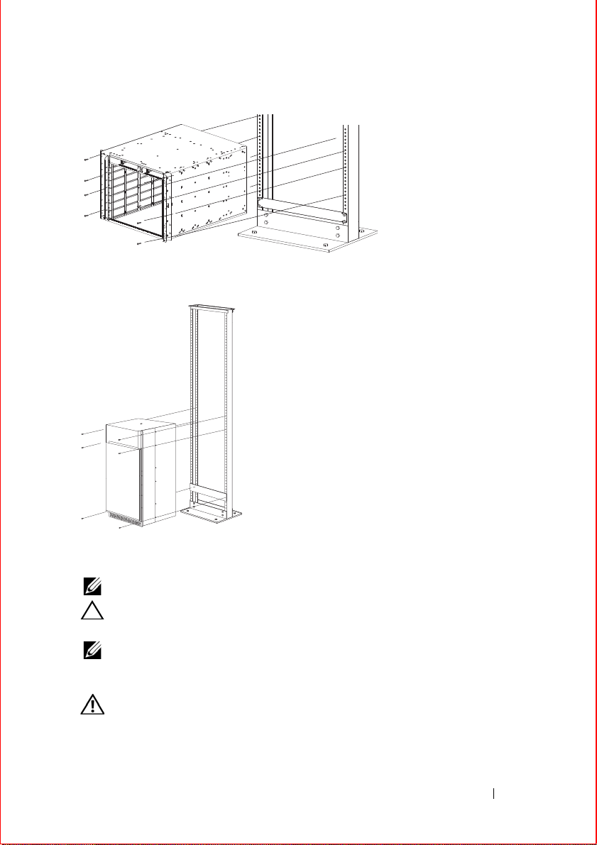
Installing E300 Chassis into Rack
FN00046d
Installing E600i and 1200i into Rack
Attach a Ground Cable to the Chassis
NOTE: The rack installation ears are not suitable for grounding.
CAUTION: Grounding conductors must be made of copper. Do not use
aluminum conductors.
NOTE: Coat the lugs with an anti-oxidant compound prior to crimping. Bring any
un-plated mating surfaces to a shiny finish, and coat with an anti-oxidant prior to
mating. Plated mating surfaces must be clean and free from contamination.
WARNING: You must complete the ground connection before proceeding
with the DC PEM installation. It is also recommended that you complete the
grounding before connecting the AC PSU power.
Installing the Hardware 7
Page 10
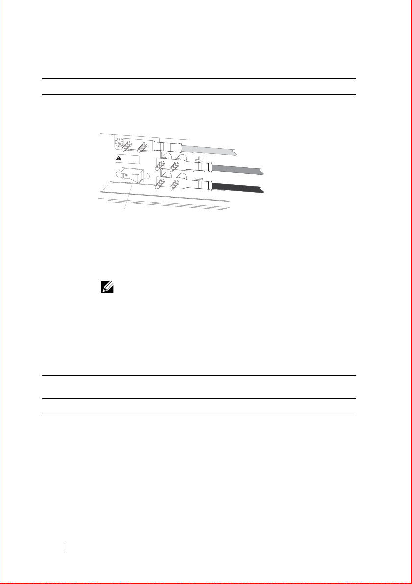
E300 DC PEM Chassis Ground
MAKE GROUND CONNECTION FIRST
CAUTION - CAUTION -
Use copperUse copper
conductors onlyconductor
s only
(-) -48V cable, typically black
Ground cable, typically green or
green with yellow stripes
(+) Return cable, typically red
Over-current protector switch
Step Task
1 Locate the chassis ground connector studs on the PEM front panel. The
two studs on the upper left are the ground connection.
2 Remove all nuts and washers from the two ground studs.
3 Apply a coat of anti-oxidant paste to the connector studs.
4 Install the grounding cable. This cable is typically green or green and
yellow.
NOTE: T e rmination points require UL-listed 2-ho le lug with 1/4-
inch holes on 3/4-inch spacing.
5 Replace the two washers and nuts on the studs.
6 Secure the nuts with a nut driver or torque wrench (not to exceed 4
ft/lbs).
7 Connect the opposite end of the grounding cable to the appropriate
nearest grounding.
E600i TeraScale and ExaScale DC Chassis Ground
Step Task
1 Remove one outer nut and one washer from each of the six studs. The
2 Locate the chassis ground connector studs on the PEM front panel. The
8 Installing the Hardware
inner nut should remain tight on the stud, at no more than 25 inch-lbs.
two bottom studs are the ground connection.
Page 11
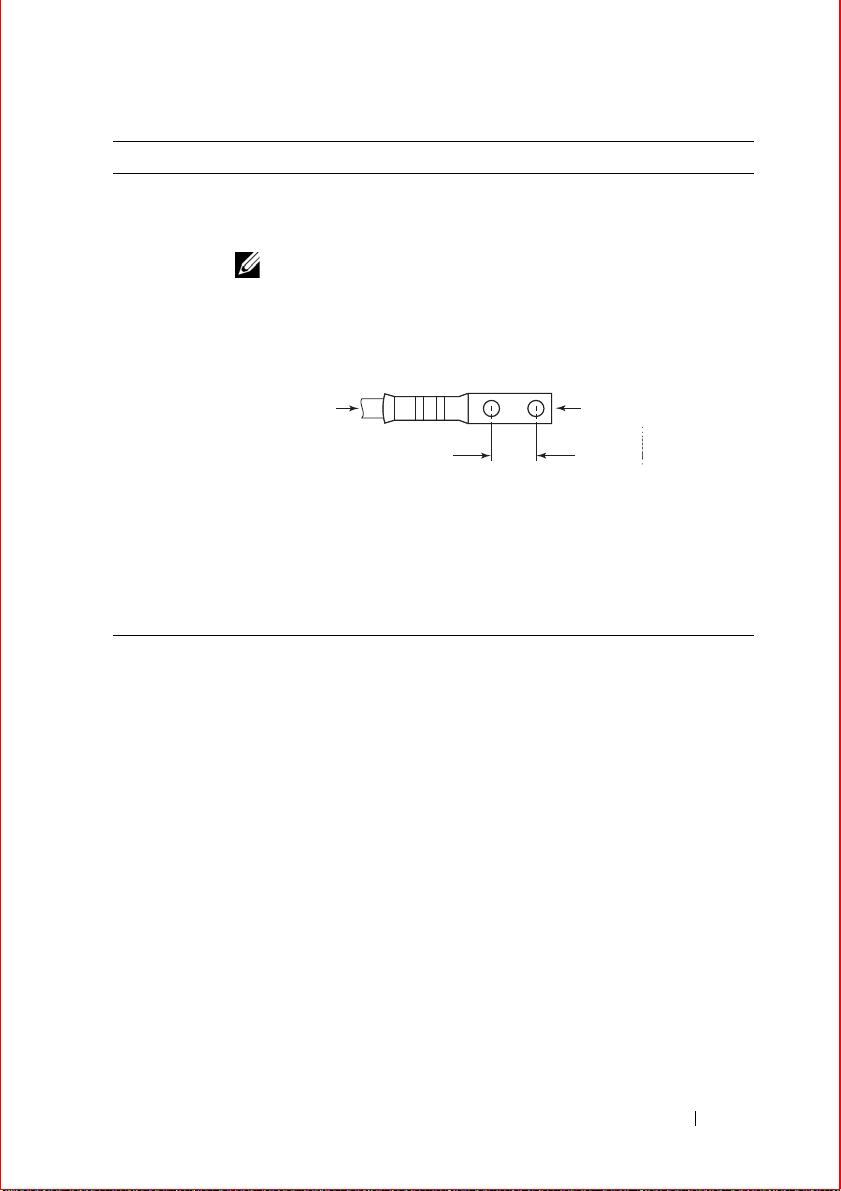
Step Task
0.750"
High-strand-count
conductor
diameter
2 Holes
All measurements in inches.
FN00011A
0.267
3 Attach the grounding cable onto the ground studs. The grounding cable
must comply with your local electrical codes in size and color (typically
the color is green or green with yellow stripe),
NOTE: Grounding cables must be terminated only with a UL-
listed 2-hole lug with 1/4-inch holes on 3/4-inch spacing.
Cable Connector Required for E600i DC
4
Replace the two washers and nuts.
5 With a 7/16-inch box or socket wrench, tighten the nuts to 25 in-lbs.
6 Connect the opposite end of the grounding cable to the nearest
appropriate facility grounding post.
Installing the Hardware 9
Page 12
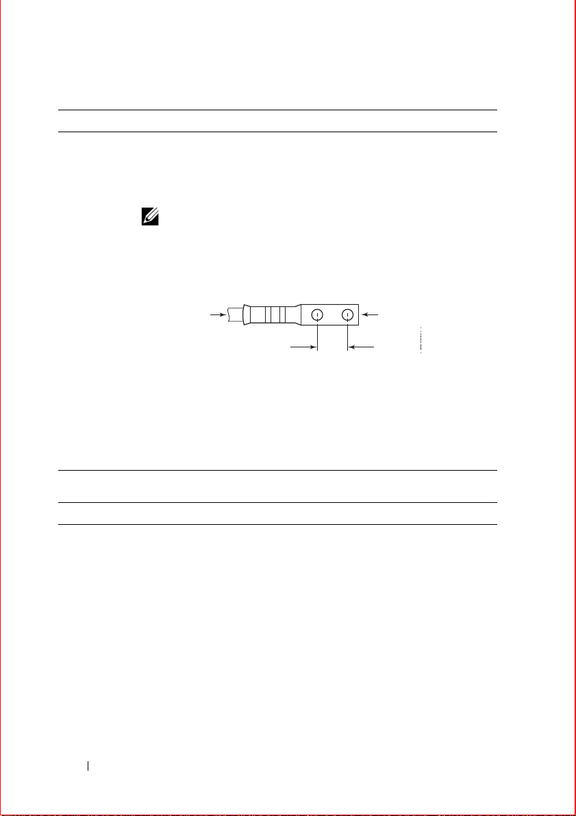
E1200i TeraScale and ExaScale AC Chassis Ground
0.750"
High-strand-count
conductor
diameter
2 Holes
All measurements in inches.
FN00011A
0.267
Step Task
1 Locate the chassis ground connector nuts on the rear of the chassis.
2 Install the grounding cables to the ground nuts. The grounding cable
must comply with your local electrical codes in size and color (typically
the color is green or green with yellow stripe).
NOTE: Grounding cables must be terminated only with a UL-
listed 2-hole lug with 1/4-inch holes on 3/4-inch spacing.
Cable Connector Required for E1200i AC
3
4 Tighten the bolt (torque should not exceed 25 inch/lbs).
5 Connect the opposite end of the grounding cable to the nearest
E1200i TeraScale and ExaScale DC Chassis Ground
Step Task
1 Remove one outer nut and one washer from each of the six studs. One
2
10 Installing the Hardware
Use ANSI UNC 1/4-20 x 12 bolt.
appropriate facility grounding post.
nut should remain, tight on the stud. If the inner nut is loose, re-tighten it
to 25 inch/lbs, maximum.
Locate the chassis ground connector stud s on the PEM fron t p anel. The
two rightmost studs are the ground connection.
Page 13
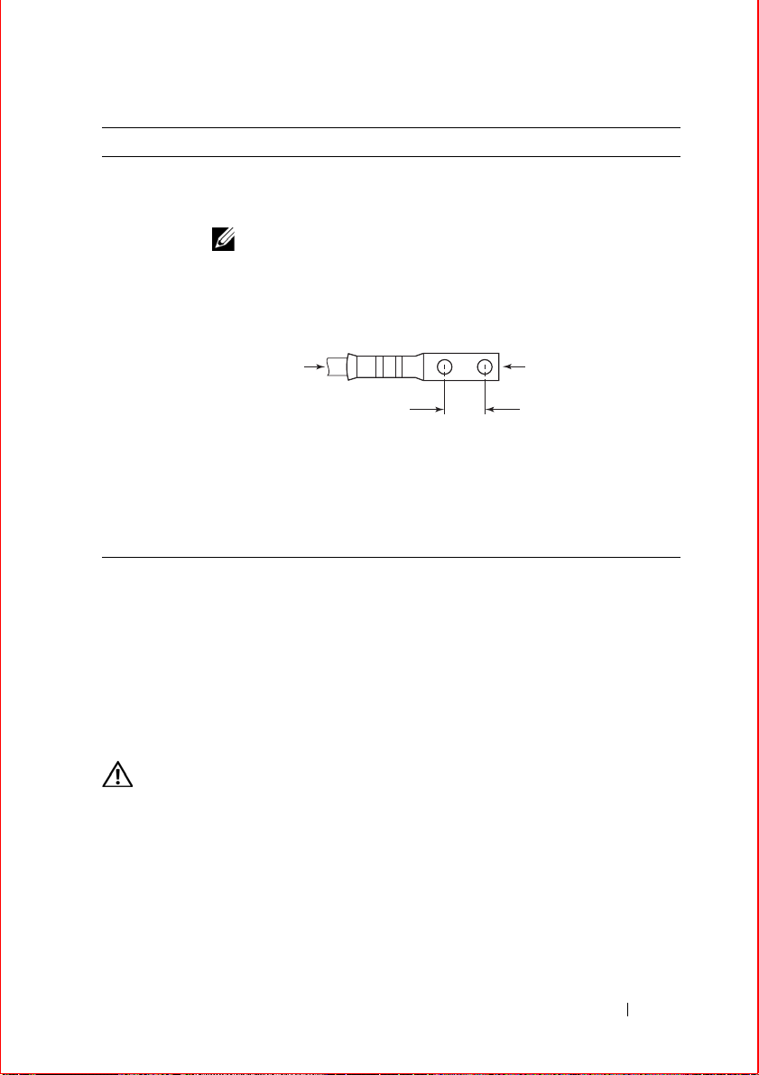
Step Task
0.750"
High-strand-count
conductor
diameter
2 Holes
All measurements in inches.
0.267
3
Install the grounding cables to the ground studs. The grounding cable must
comply with your local electrical codes in size and color (typically the
color is green or green with yellow stripe).
NOTE:
Grounding cables must be terminated only with a UL-
listed 2-hole lug with 1/4-inch holes on 3/4-inch spacing.
Cable Connector Required for E1200iDC PEM
4 Replace the two washers and nuts on the studs.
5 With a 7/16-inch box or socket wrench, tighten the nuts (torque should
not exceed 25 inch/lbs).
6 Connect the opposite end of the grounding cable to the nearest
appropriate facility grounding post.
Installing Power Modules
This section provides instructions to install AC Power Supply Units (PSUs) and
DC Power Entry Modules (PEMs) in each E-Series system. E-Series systems
may contain only one type of power module—AC or DC.
Unless otherwise stated, each AC and DC power supply for each E-Series
system is shipped with a Dell Force10-approved power cord and only that cord
should be used to connect the power supply to the appropriate outlet.
E300 AC Power Modules
The E300 system requires a minimum of two AC Power Supplies.
WARNING: To prevent electrical shock, make sure the system is grounded
properly . If you do not ground your equipment correctly, excessive emissions
may result. Use a qualified electri cian to en su re that the power cables meet
your local electrical requirements.
Installing the Hardware 11
Page 14
WARNING: Electrostatic discharge (ESD) damage can occur when
components are mishandled. Always wear an ESD-preventive wrist or footheal ground strap when handling chassis components.
CAUTION: Before removing and replacing a power supply module,
determine if the E300 is in full facility redundancy or non-redundant power.
Operating in non-redundant power will require a complete system power off
when removing and replacing a power supply.
CAUTION: The power cord is the main power disconnect device; ensure that
the socket-outlet is located/installed near the equipment and is easily
accessible.
The E300 contains four power supply slots in the rear of the chassis.
Each AC power supply contains two LEDs: Status and AC.
To install an AC power supply:
Step Task
1 Togg le the Standby Switch of the power supply to the standby position.
NOTE: If the E300 is already operating in redundant mode, you
can insert a new power supply without shutting down the E300.
2 Slide the power supply into any open power supply slot.
CAUTION: Fill all four power supply slots with power
supplies or filler blanks before tightening the power supply
screws. Doing this ensures that each power supply is aligned
correctly . Attempting to tighten screws without all power
supply slots filled will cause misalignment with screw holes,
which might damage the chassis permanently.
12 Installing the Hardware
Page 15
Step Task
3 For bottom units, ensure that the EMI gasket along the edge of each
power supply is compressed smoothly before securing each power
supply into place using the captive screws.
For top units, it may be necessary to lift the unit slightly to install the
captive screws.
As a best practise, insert the two captive screws of each power supply by
hand before tightening them all.
CAUTION: Tighten the screws with a #2 Phillips screwdriver.
Use no more than eight pounds of torque (light torque with a
manual screwdriver). Too much torque can damage fasteners
and that improper use of power drivers can cause even greater
damage.
4 Plug the AC power cord into the AC power inlet in the face of the powe r
supply.
5 Plug the AC power cord into an AC power outlet.
6 Toggle the standby switch of the power supply to the On position.
NOTE: Power modules are not field serviceable.
E300 DC Power Modules
The E300 supports a minimum of one DC PEM. Y ou must have only one type of
power module in the chassis; you cannot install a mixture of power modules.
You must provide your own cables to connect to a remote power source (a
circuit breaker panel, for example) in your equipment rack or facility. Cables
must be sized to meet the following criteria:
• Rated for 60A service to allow for a fully lo aded E300 system per NEC in the
United States or internationally, per local safety codes.
• Limit voltage drop across the cable length to 0.5V or less.
Before you make the cable connections, apply a coat of anti-oxidant paste to
unplated metal contact surfaces. File unplated connectors, braided straps, and
bus bars to a shiny finish. It is not necessary to file and coat tinned, solderplated, or silver-plated connectors or other plated connection surfaces, such as
those on the PEM studs.
Installing the Hardware 13
Page 16

NOTE: Please take precautions against over-tightening the screws or nuts on this
device.
Installing a DC PEM
Step Task
1 Turn the remote power source (the circuit breaker panel) to the OFF
position.
2 Turn the over current protector (located on the PEM front panel) to the
OFF position.
3 Loosen the PEM safety cover retaining screw and remove the cover.
4 Slide the PEM into power slot 0 or 1.
CAUTION: Fill all power supply slots with power supplies or
filler blanks before tightening the power supply screws. Doing
this ensures that each power suppl y is ali g n ed correctly.
Attempting to tighten screws without all power supply slots
filled will cause misalignment with screw holes, which might
damage the chassis permanently. If you are only installing one
PEM, replace the empty slot with two blank panels. (CCE300-BLNK-PWR.)
5 Tighten the two locking screws on each module with a #2 Phillips
screwdriver to secure the PEM in place. As a best practise, insert all
screws before tightening each one.
6 Remove the outer nut and washer from each of the remaining studs.
7 Connect the -48 VDC and Return cables from each PEM to the remote
power sources.
a
Verify that the remote power source is in the OFF position.
b
Locate the appropriate studs on the PEM front panel. The two top
studs are the return (+) connection. The cable attach ed to thes e s tu ds
is typically red. The two bottom studs on the PEM are the -48 VD C () connection. The cable attached to these studs is ty pica lly b la ck .
Power cables must be terminated only with a UL-listed 2-hole lug to
accommodate 1/4-inch studs with 3/4-inch spacing.
c
Apply a coat of anti-oxidant paste to the connector studs.
d
Replace the washers and nuts on the studs.
e
Route the terminated cables out toward the rack rail.
f
Secure the nuts with a nut driver or torque wrench (no t to exce ed 4
ft/lbs).
14 Installing the Hardware
Page 17

Step Task
8 Replace the safety cover and tighten the captive screw with a #2 Phillips
screwdriver.
9 Turn the Over Current Protector to the ON position.
10 Turn the remote power source (the circuit breaker panel) to the ON
position.
E600i AC Power Modules
The E600i requires a minimum of two AC Power Supplies.
Power Supply Input Minimum (N) Redundancy
220 VAC 3 N+1
100 VAC 2 N+1
The chassis has four power supply slots. You may install AC power suppl ies in
any slot.
WARNING: Class 1 laser product.
The 2500W AC Power Supply Unit is capable of operating at either 100 V AC or
220 VAC.
CAUTION: Before removing and replacing a power supply unit, determine if
the E600i is in full redundancy or non-redundant mode. Operating in nonredundant mode will require a complete system power off when removing and
replacing a power supply.
NOTE: Do not mix power supply versions. Installing a 2500W-AC2 power supply
into a chassis with 2500W-AC power supplies already installed may result in
unpredictable behavior. FTOS will declare an alarm when the PSUs are mixed.
To install an AC power supply:
Step Task
1 Verify that the power switch on the power supply is in the OFF position.
2 Orient the power supply handle to the left, and slide the backplane
connector end into a power supply slot.
Installing the Hardware 15
Page 18

Step Task
3 Secure the power supply into place by tightening the two locking screws
to 5 in-lbs.
4 Plug an AC power cord into the socket on the front of the unit:
a
Loosen the power cord retainer thumb screw.
b
Rotate the retainer clockwise away from the socket and plug the
power cord into the socket.
c
Rotate the retainer counter clockwise over the power cord, and
tighten the thumb screw to secure the power cord.
5 Plug the AC power cord into an AC outlet.
6 Toggle the power supply switch to the ON position, and verify that
Status LED lights green.
E600i DC Power Modules
The system requires a minimum of one load-sharing PEM to operate, but two
are recommended for redundancy. Connect the E600 PEMs to the appropriate
branch circuit protection as defined by local electrical codes.
You must provide your own cables to connect to a remote power source in your
equipment rack. Verify that your cables are:
• Rated for at least 80A service to allow for a fully load ed E600i system at low
input voltage per your local electrical codes.
• Limit voltage drop across the cable length to 0.5V or less.
Before you make the cable connections, apply a coat of anti-oxidant paste to
unplated metal contact surfaces.
File unplated connectors, braided straps, and bus bars to a shiny finish. It is not
necessary to file and coat tinned connectors or other plated connection surfaces,
such as on the PEM studs.
Installing a DC PEM
Step Task
1 Make sure that the remote power source (the circuit breaker panel) is in
the OFF position.
2 Make sure that the over current protector (located on the PEM front
panel) is in the OFF position.
16 Installing the Hardware
Page 19

Step Task
3 Loosen the retaining screw and remove PEM safety cover.
4 Slide the backplane connector end of the PEM into Power Supply Slot 1
or 3. Secure the PEM to the chassis by tighten the two locking screws.
E1200i AC Power Modules
When installing the AC power supplies in the E1200i system, make note of the
following:
• E1200i ExaScale AC system: The E1200i AC system requires a minimum of
3 AC power supplies in a shelf (0, 1, 2 or 3, 4, 5) to operate. For full
redundancy use 6 power supplies so that if one power supply fails in one
shelf, the system remains operational operates with the 3 power supplies in
the other shelf. T o comp ly with safety agency and E MI regulations, you mus t
install the AC-cord retainer over all power cords. The E1200i AC chassis
contains 6 AC power supply slots.
• E1200iT e raScale AC system: T he E1200i A C system requires a minimum of
two AC power supplies to operate, three for power redundancy, four for
facility redundancy (2+2), and 6 for 3+3 redundancy. To comply with safety
agency and EMI regulations, you must install the AC-cord retainer over all
power cords. The E1200i AC chassis contains six AC power supply slots.
NOTE: If you are installing only two power supplies, they must be installed in the
same row. FT OS will generate an error me ssage if the two power supplies are not in
the same row.
NOTE: The On/Standby switch disconnects power to the rest of the chassis from
all 6 AC power supplies. When the AC cord is attached, power supply fans will
spin and the LEDs will indicate status while the On/Standby switch is in Standby.
CAUTION: An E1200i AC power supply still has power after extraction, and
has completely powered off when the fans have stopped rotating. When
replacing a power supply, to avoid arcing and discoloration of the supply and
the chassis pins, please wait for the fans to stop rotating before reinserting the
supply.
Step Task
1 Make sure that the On/Standby switch, located on the left side of plug
AC-0, is in the Standby (up) position.
Installing the Hardware 17
Page 20

Step Task
2 Loosen the cord retainers locking screws (if needed) and tilt the AC-
cord retainer up approximately 15 degrees and gently slide the cover
away from the chassis.
3 Slide the power supplies into their slots until the module front is flush
with the shelf front.
4 Connect the Power Supply cord to the designated socket.
5 Re-install the AC-cord Retainer by tilting approximately 15 degrees and
gently sliding in the long edge just above the AC cords.
6 Secure the retainer by tighten the locking screws on either side of the
retainer.
WARNING: Leakage Current (High T ouch Current) in AC-powered systems:
AC power cords are secured to the power inlet using the provided brackets.
The power cord plugs must be secured to the building outlets by the qualified
chassis installer or a qualified electrician.
E1200i DC Power Modules
The E1200i DC system requires a minimum of one DC Power Entry Module
(PEM) to operate, but two are recommended for redundancy. To comply with
safety agency and EMI regulations, you must install covers on all power supply
slots not containing a PEM. Connect the PEMs to the appropriate branch circuit
protection as defined by local electrical codes.
The E1200i DC chassis contains two DC PEM slots.
You must provide your own cables to connect to a remote power source (for
example, a circuit breaker panel) in your equipment rack or office. Cables must
be sized to meet the following criteria:
• Rated for at least 150A service to allow for a fully loaded E 1200i DC sy stem
at low input voltage per your local electrical codes.
• Limits voltage drop across the cable length to 0.5V or less.
Before you make the cable connections, apply a coat of antioxidant paste to unplated metal contact surfaces. File un-plated connectors, braided straps, and bus
bars to a shiny finish. It is not necessary to file and coat tinned connectors or
other plated connection surfaces, such as on the E1200i DC PEM studs.
18 Installing the Hardware
Page 21

WARNING: An external disconnect shall be provided and shall be easily
accessible. Dell Force10 recommends that you use a 150A circuit breaker.
Use the following steps to install a DC PEM:
Step Task
1 Make sure that the remote power source (the circuit breaker panel) is in
the OFF position.
2 Make sure that the over-current protector (located on the PEM front
panel) is in the OFF position.
3 Loosen the retaining screw and remove the PEM safety cover.
4 Slide the PEM into the 0 or 1 slot:
a
Lift up and hold the PEM interlock lever and carefully push the unit
inward to fully seat it to the backplane. When the PEM is fully
inserted, the interlock lever will drop to hold the PEM in position.
b
Tighten the tw o l o c k i ng screws with a #2 Phillips screw driv er to
secure the PEM. Do not exceed 5 inch/lbs torque.
5 Connect the -48 VDC and Return cables from each PEM to the remote
power sources (circuit breakers A and B).
a
Check that the remote power sources (for example, circ uit bre ak ers)
are in the OFF position.
b
Locate the appropriate studs on the PEM front panel.
c
The two left most studs on the PEM are the -48 VDC (-) connection.
The cable attached to these studs is typically black. The two m iddle
studs are the return (+) connection. The cable attache d to th es e studs
is typically red.
d
Install the -48 VDC and Return cables on the studs. The cables
should be of the size and color to comply with local electrical codes.
NOTE: Power cables must be terminated only with a UL-listed 2-
hole lug with 1/4-inch studs with 3/4-inch spacing.
e
Replace the washers and nuts on the studs.
f
With a 7/16-inch box or socket wrench, tighten the nuts.
6 Route the terminated cables down and toward the rack rail.
7 Replace the safety cover and tighten the captive screw with a #2 Phillips
screwdriver.
Installing the Hardware 19
Page 22

Step Task
8 Check that the over-current protector (located on the PEM front panel)
is in the OFF position. Energize the remote power source. The Voltage
LED should be green. If it is amber, the -48 VDC and Return cables are
connected incorrectly or are reversed.
Installing RPMs, Line Cards, and SFMs
Unpacking Cards
WARNING: Electrostatic discharge (ESD) damage can occur when
components are mishandled. Always wear an ESD-preventive wrist or footheel ground strap when handling RPMs, SFMs, or line cards. Connect your
ESD strap to the grounding plug located on the front of the chassis. See Figure
2 for ESD strap connector location. After you remove the original packaging,
place RPMs, SFMs, and line cards on an antistatic surface.
CAUTION: Do not supply power to your system until the power supplies and
fan tray(s) are installed and verified, and RPMs, SFMs, line cards, and any
blank panels are installed.
Blank Panels
CAUTION: To avoid a chassis over-temperature condition, install blanks for
RPMs, SFMs, and line card slots not in use. Always replace cards or blanks
immediately.
Blank panels for RPMs, SFMs, and line cards must be installed in empty slots to
control airflow. Blank panels are shipped with the system to ensure that all
chassis slots are installed with operational modules or blanks.
E300
RPMs
The E300 system requires the installation of at least one RPM, although two are
recommended for redundancy. RPMs are designed to be installed in either the
R0 or R1 slot. Do not force RPMs into line card slots. RPMs are keyed
differently than line cards to prevent improper installation.
20 Installing the Hardware
Page 23

Installing the RPMs and Line Cards
CAUTION: Use of controls or adjustments or performance of procedures
other than those specified herein may result in hazardous laser exposure.
NOTE: Line cards are hot swappable.
Step Task
1 Hold the card by the edges. A void touching the printed circuit board and
connector pins. Extend the left and right card levers before you insert
the card into the slot.
2 Align the card with the guide and gently slide it into the slot until you
feel the connectors engage with the chassis backplane.
3 Rotate the levers to seat the backplane connectors and line card in place.
4 Secure card and blanks in place by tightening the left and right captive
screws on each card.
5 Follow the same installation procedure for the remaining cards and slots.
Installing Switch Fabric Modules (SFMs)
Two SFMs are required for the E300 system to operate optimally.
Step Task
1 Remove an SFM from the anti-static packaging. Hold the card by the
edges. Avoid touching the printed circuit board and connector pins.
Extend the card lever before you insert the card into the slot.
2 Align the SFM with the guide and gently slide it into the slot until you
feel the connectors engage with the chassis backplane.
3 Rotate the lever to seat the backplane connectors and card in place.
4 Secure each SFM in place by tightening the captive screw.
5 Continue the process for the remaining SFMs.
6 Install blank panels in all unused slots.
NOTE: If you are not operating the system with SFM redundancy, install a blank
panel in the unused slot.
Installing the Hardware 21
Page 24

E600i
RPMs
The E300 system requires the installation of at least one RPM, although two are
recommended for redundancy. RPMs are designed to be installed in either the
R0 or R1 slot. Do not force RPMs into line card slots. RPMs are keyed
differently than line cards to prevent improper installation.
Line Cards
Your E600i configuration requires a minimum of one line card. Line cards are
hot swappable.
Installing the RPMs and Line Cards
CAUTION: Use of controls or adjustments or performance of procedures
other than those specified herein may result in hazardous laser exposure.
NOTE: Line cards are hot swappable.
Step Task
1 Hold the card by the edges. A void touching the printed circuit board and
connector pins. Extend the left and right card levers before you insert
the card into the slot.
2 Align the card with the guide and gently slide it into the slot until you
feel the connectors engage with the chassis backplane.
3 Rotate the levers to seat the backplane connectors and line card in place.
4 Secure card and blanks in place by tightening the left and right captive
screws on each card.
5 Follow the same installation procedure for the remaining cards and slots.
Installing Switch Fabric Modules (SFMs)
A minimum of four SFMs are required in order for the E600i system to operate
properly. There is an additional slot available for a redundant SFM.
NOTE: If you are not operating the system with SFM redundancy, install a blank
panel in the unused slot.
22 Installing the Hardware
Page 25

Step Task
1 Remove an SFM from the anti-static packaging. Hold the card by the
edges. Avoid touching the printed circuit board and connector pins.
Extend the card lever before you insert the card into the slot.
2 Align the SFM with the guide and gently slide it into the slot until you
feel the connectors engage with the chassis backplane.
3 Rotate the lever to seat the backplane connectors and card in place.
4 Secure each SFM in place by tightening the captive screw.
5 Continue the process for the remaining SFMs.
E1200i
RPMs
The E1200i system requires the installation of at least one RPM, although two
are recommended for redundancy.
• Do NOT remove the cards from their protective bags until you are ready to
install them in a chassis.
• When you are ready to install the cards, unwra p and install one card at a time,
starting with the right-most slot (Slot 13 for line cards, Slot R1 for RPMs,
and Slot 9 for SFMs) ending with the l eft-most slot (Slot 0 for line cards, S lot
R0 for RPMs, and Slot 0 for SFMs).
RPMs are designed to be installed in either the center R0 or R1 slots. Since
FTOS searches for an RPM in slot 0 first, Force 10 recommends you install your
RPM in slot 0 when only running with one RPM. Do not force RPMs into line
card slots. RPMs are keyed differently than line cards to prevent improper
installation.
Line Cards
Your E1200i configuration requires a minimum of one line card. Line cards are
hot-swappable. There are 14 line card slots available in the E1200i chassis. A
minimum of one line card is required for operation. Line cards are installed in
slots 0 through 13. Ports on line cards are numbered from the top, starting from
0.
Installing the Hardware 23
Page 26

Preparing and Installing RPMs and Line Cards
To prolong the life of the EMI seals, begin installing cards in the right-most slot
(slot 13), filling the slots leftward (slot 12, then slot 11, then slot 10, and so on).
Step Task
1 Remove the line card from its box and carefully remove the line card
from the anti-static packaging.
2 Align the RPM with the guide and gently slide it into the slot until you
feel the connectors engage with the chassis backplane.
NOTE: Hold the card by the edges. Avoid touching the printed
circuit board and connector pins. Extend the top and bottom card
levers before you insert the card into the slot.
3 Rotate the levers to seat the backplane connectors and line card in place.
4 Secure card and blanks in place by tightening the top and captive screws
on each card.
5 Follow the same installation procedure for the remaining cards and slots,
in the appropriate order.
Installing Switch Fabric Modules (SFMs)
A minimum of eight SFMs are required in order for the E1200i system to
operate properly. Slot 9 allows for a redundant SFM, allowing up to ten SFMs in
the E1200i system.
CAUTION: If you are not operating your system with a redundant (tenth)
SFM, you must install an SFM blank to avoid overheating and ensure EMI
containment.
Install SFMs from the right-most slot (9) to the left-most slot (0).
Step Task
1 Remove an SFM from the anti-static packaging.
2 Align the SFM with the guide and gently slide it into the slot until you
feel the connectors engage with the chassis backplane.
NOTE: Hold the SFM by the edges. Avoid touching the printed
circuit board and connector pins. Extend the top and bottom card
levers before you insert the card into the slot.
24 Installing the Hardware
Page 27

Step Task
3 Rotate the lever to seat the backplane connectors and card in place.
4 Secure each SFM in place by tightening the captive screw.
5 Continue the process for the remaining SFMs.
6 Align any blank panels with the guides and gently slide toward the
backplane. Secure each blank panel by tightening the single captive
screw.
Power Up Sequence
WARNING: Make sure that the switch on the remote power source is in the
OFF position until you are ready to supply power to the chassis.
Follow the instructions in this section to power up all E-Series TeraScale and ESeries ExaScale systems.
Preparation
Before you supply power to your chassis, re-inspect your equipment rack and
chassis, verify that:
• The equipment rack is properly secured and grounded.
• The chassis is bolted and secured into your equipment rack.
• Each power supply module (AC or DC) is properly installed and grounded.
• Each power supply module’s switch is in the OFF position.
• The safety covers are installed on each DC PEM.
• Power cables connect to a compliant remote power source.
• The fan tray is installed and cannot be removed by pulling on the fan tray
handles.
• All line cards, RPMs, and SFMs are properly installed and secured.
• All chassis slots are filled. Blank panels and covers are installed in all empty
slots.
Installing the Hardware 25
Page 28

Supplying Power
Step Task
1 Energize the remote power source.
2 Flip the switch on the AC power supplies or DC PEM to the ON
position.
3 In a DC PEM, the Status LED should be green.
In an AC Power Supply, the top Input AC and Output LEDs should be
green. If these LEDs are not lit or the Status LED is amber on a DC
PEM, check that the unit is properly installed. Verify the power source.
If the LEDs remain unlit, power off all modules and replace the unit.
4 The fan tray LED should be green (online). Verify that air is flowing
through the chassis.
If the fans are not operating properly or air is not flowing through the
chassis, power off the chassis at the power module. Ensure that the fan is
properly installed. Verify the power source. If the fan impeller LED
remains unlit, replace the fan impeller.
To turn the power off on the power modules, use one of the following met hods:
• On the DC PEMs, flip the switch to the OFF position. Make sure the AC
power supplies Status LEDs are not lit.
• On the AC Power Supplies, flip the switch to the OFF position and unplug
the power cord from the socket on the front of the Power Supply. Make sure
the Input AC and Output DC LEDs are not lit (they may flash as they power
down.)
Booting to the CLI Prompt
After you supply power to the system, the following should occur:
• The fans should be operating.
• The green (online) fan tray, power module, RPM, SFM, and line card LEDs
should be lit and remain lit as long as the system is receiving power and is
operational.
When you supply power to the system, the system performs a series of power-on
self tests. RPM, line card, and SFM LEDs blink as the diagnostic programs run.
No user interaction is required at this point. Observe the process on your console
26 Installing the Hardware
Page 29

monitor. When the boot process is complete, the card LEDs remain online
(green) and the console monitor displays the Command Line Interface (CLI)
prompt.
NOTE: Do not press any keys or control sequences at any time during the boot
process. Doing so may cause the boot process to terminate.
CAUTION: Leakage Current (High T ouch Curr ent): The AC power cords are
secured to the power inlet using the provided bracket. The power cord plugs
must be secured to the building outlets by the chassis installer or a qualified
electrician.
Fans
For complete information on installing system FAN trays, refer to your system's
installation guide.
E300
Your E300 chassis contains one field-replaceable fan tray. Air flows through the
system toward the fans and is exhausted on the fan side of the chassis. Air
circulates from the right side to the left. Minimum air flow is 665 cubic feet per
minute (CFM).
E600i TeraScale and E600i ExaScale
Your E600i chassis contains one field-replaceable fan tray. Air flows through
the system from a filtered intake vent located in the lower part of the chassis. Air
circulates from the bottom front side to the back side and exhausts primarily
through a top rear vent. The variable speed fan rate is reduced at normal
operating temperatures and fans reach full speed at 40° C (104° F).
E1200i TeraScale and E1200i ExaScale
Your E1200i chassis contains two field-replaceable fan trays. Air flows through
the system from a filtered-intake vent located in the lower part of the chassis.
Air circulates from the bottom front (and sides) to the back and exhausts through
a top rear vent. The variable fan speed is reduced at normal operating
temperatures and increases to full speed as operating temperatures increase, up
to 104° F (40° C).
Installing the Hardware 27
Page 30

E300 Specifications
E300 Chassis Physical Design
Parameter E1200i AC Specifications
Height 14 inches (35.6 cm)
Width 17.4 inches (44.2 cm)
Depth (without cable management
system)
Chassis weight with factory-installed
components (backplane and air filter)
Weight fully loaded (backplane, air
filter, 1 fan tray, 2 SFMs, 2 RPMs, and 6
line cards)
Thermal Output
Maximum for fully loaded chassis 2500 W (8500 BTU/hour)
Normal operating conditions (25 deg.C,
-48V-line)
Minimum for chassis with one 24-port
1GE line card
E300 Environmental Parameters
Parameter Specifications
Operating
Temperature 40° to 105°F (5° to 40°C)
Maximum altitude No performance degradation to 10,000 feet (3,048 meters)
Relative humidity 5 to 85 percent, non-condensing
Non-operating
Temperature -40° to 158°F (-40° to 70°C)
Maximum Altitude 15,000 feet (4,572 meters)
Relative Humidity 5 to 95 percent, non-condensing
24 inches (61 cm)
90 pounds (approx.) (41 kg)
170 pounds (approx.) (77 kg)
2000 W (6800 BTU/hour)
800 W (2700 BTU/hour)
28 Installing the Hardware
Page 31

E300 AC Power Supplies Power Requirements
Parameter Specifications
Nominal input voltage 100 - 240 VAC 50/60 HZ
Maximum AC Power Supply Input
Current (based on 800W output for
100/120V line and 1200W output for
200/240V line.)
Maximum System Power Input
3 AC Power Supply Operation
3 AC Power Supply Operation
10 A @ 100 VAC per AC Power Supply
8.3 A @ 120 VAC per AC Power Supply
7 A @ 200 VAC per AC Power Supply
5.8 A @ 240 VAC per AC Power Supply
3000W
1000W @ 100V
950W @ 200V
E300 DC PEM Power Requirements
Parameter Specifications
Maximum System Power Dissipation 2400W
Maximum DC PEM Input Current 60A
Maximum System Power Input
3 AC Power Supply Operation
3 AC Power Supply Operation
3000W
1000W @ 100V
950W @ 200V
E300 Module Power Requirements
Module Power Requirement in Watts (in
BTU/hour)
SFM 55W (188 BTU/hour)
E300 RPM 115W (BTU/hour)
E300 fan tray 85 W
E600i Specifications
E600i TeraScale Chassis Physical Design
Parameter Specifications
Height 28 inches (71.1 cm)
Installing the Hardware 29
Page 32

Parameter Specifications
Width 17.4 inches (44.2 cm)
Depth (without cable management
system)
Chassis weight with factory-installed
components (backplane and air filter)
Weight fully loaded (backplane, air
filter, fan tray, SFMs, RPMs, and 7 line
cards)
Maximum Thermal Output
NOTE: Thermal output is directly proportional to system configuration and
number of line cards.
Maximum for fully loaded chassis 120 VAC powered: 4705W (16,065
21.5 inches (54.6 cm)
81 pounds (36.7 kg)
242 pounds (109.8 kg)
BTU/hour)
200/240 VAC powered: 4250W (14,500
BTU/hour)
DC powered: 2800W (9600 BTU/hour)
E600i TeraScale Environmental Parameters
Parameter Specifications
Operating
Temperature 32° to 104°F (0° to 40°C)
Maximum altitude No performance degradation to 10,000 feet (3,048 meters)
Relative humidity 5 to 85 percent, non-condensing
Non-operating
Temperature -40° to 158°F (-40° to 70°C)
Maximum Altitude 15,000 feet (4,572 meters)
Relative Humidity 5 to 95 percent, non-condensing
E600i TeraScale AC Power Supply Unit Requirements
Parameter Specifications
Nominal input voltage 120 - 240 VAC 50/60 Hz
30 Installing the Hardware
Page 33

Parameter Specifications
Maximum AC Power Supply Input 16 A @ 100 VAC per module
12 A @ 200 VAC per module
Maximum Thermal Output (3,172 W)
Maximum Thermal Output (2,906 W)
Maximum AC Supply Input Current
(based on 2500 W output for 100/120V
and 200/240V lines.)
Maximum System Power Input 3.5 KVA @ 100/120 VAC
Maximum Power Consumption 3,422 W at 100/120 VAC
10,822 BTU/hour at 100/120 VAC
9,914 BTU/hour at 200/240 VAC
11.6 A @ 100 VAC
9.7 A @ 120 VAC
8.0 A @ 200 VAC
6.7 A @ 240 VAC
3.2 KVA @ 220/240 VAC
3,156 W at 200/240 VAC
E600i ExaScale Chassis Physical Design
Parameter Specifications
Height 28 inches (71.1 cm)
Width 17.4 inches (44.2 cm)
Depth (without cable management
system)
Chassis weight with factory-installed
components (backplane and air filter)
Weight fully loaded (backplane, air
filter, fan tray, SFMs, RPMs, and 7 line
cards)
Maximum Thermal Output
21.5 inches (54.6 cm)
81 pounds (36.7 kg)
242 pounds (109.8 kg)
NOTE: Thermal output is directly proportional to system configuration and
number of line cards.
Installing the Hardware 31
Page 34

Parameter Specifications
Maximum for fully loaded chassis 120 VAC powered: 4705W (16,065
BTU/hour)
200/240 VAC powered: 4250W (14,500
BTU/hour)
DC powered: 2800W (9600 BTU/hour)
E600i ExaScale Environmental Parameters
Parameter Specifications
Operating
Temperature 32° to 104°F (0° to 40°C)
Maximum altitude No performance degradation to 10,000 feet (3,048 meters)
Relative humidity 5 to 85 percent, non-condensing
Non-operating
Temperature -40° to 158°F (-40° to 70°C)
Maximum Altitude 15,000 feet (4,572 meters)
Relative Humidity 5 to 95 percent, non-condensing
E600i ExaScale AC Power Supply Unit Requirements
Parameter Specifications
Nominal input voltage 120 - 240 VAC 50/60 Hz
Maximum AC Power Supply Input 16 A @ 100 VAC per module
12 A @ 200 VAC per module
Maximum Thermal Output (3,172 W)
Maximum Thermal Output (2,906 W)
Maximum AC Supply Input Current
(based on 2500 W output for 100/120V
and 200/240V lines.)
Maximum System Power Input 3.5 KVA @ 100/120 VAC
10,822 BTU/hour at 100/120 VAC
9,914 BTU/hour at 200/240 VAC
11.6 A @ 100 VAC
9.7 A @ 120 VAC
8.0 A @ 200 VAC
6.7 A @ 240 VAC
3.2 KVA @ 220/240 VAC
32 Installing the Hardware
Page 35

Parameter Specifications
Maximum Power Consumption 3,422 W at 100/120 VAC
3,156 W at 200/240 VAC
E1200i Specifications
E1200i TeraScale Chassis Physical Design
Parameter E1200i AC Specifications E1200i DC Specifications
Height 42 inches (106.68 cm) 36.75 inches (93.35 cm)
Width 17.40 inches (44.20 cm) 17.40 inches (44.20 cm)
Depth (without cable
management system)
Chassis weight with factory-
installed components
(backplane and air filter)
Weight fully loaded
(backplane, air filter, 2 fan
trays, 10 SFMs, RPMs, and 14
line cards)
Thermal Output
Maximum for fully loaded
chassis
Minimum for chassis with one
48-port 1GE line card
22.25 inches (56.51 cm) 21.25 inches (53.98 cm)
139 pounds (approx.)
(63.05kg)
394 pounds (approx.)
(178.7 kg)
7,784W (26,578BTU/HR) 6850W (23,389 BTU/HR)
1,450W (4,951 BTU/HR) 1,450W (4,951 BTU/HR)
97 pounds (approx.) (44.00
kg)
319 pounds (approx.)
(144.70 kg)
E1200i TeraScale Environmental Parameters
Parameter Specifications
Operating
Temperature 32° to 104°F (0° to 40°C)
Maximum altitude No performance degradation to 10,000 feet (3,048 meters)
Relative humidity 5 to 85 percent, non-condensing
Shock Designed to meet Telcordia GR-63 CORE
Installing the Hardware 33
Page 36

Parameter Specifications
Vibration Designed to meet Telcord ia GR-63 CORE
Non-operating
Temperature -40° to 158°F (-40° to 70°C)
Maximum Altitude 15,000 feet (4,572 meters)
Relative Humidity 5 to 95 percent, non-condensing
Vibration Bellcore GR-63
E1200i TeraScale Power Requirements
Parameter E1200i AC Specifications E1200i DC Specifications
Nominal input voltage 200-240 VAC 50/60 Hz -44 to 60 VDC
Maximum Power
Consumption
Maximum Thermal
Output
5,734 @ 200/240 VAC 5,210 W
18,710 BTU/hour (5,484 W) 16,924 BTU/hour (4,910 W)
Maximum Input
Current
Maximum System
Power Input
(per power supply)
15.0 A @ 200 VAC
12.5 A @ 240 VAC
5.8 KVA @ 200/240 VAC
(per DC PEM)
150 A
E1200i ExaScale Chassis Physical Design
Parameter E1200i AC Specifications E1200i DC Specifications
Height 42 inches (106.68 cm) 36.75 inches (93.35 cm)
Width 17.40 inches (44.20 cm) 17.40 inches (44.20 cm)
Depth (without cable
management system)
Chassis weight with factory-
installed components
(backplane and air filter)
34 Installing the Hardware
22.25 inches (56.51 cm) 21.25 inches (53.98 cm)
139 pounds (approx.)
(63.05kg)
97 pounds (approx.) (44.00
kg)
Page 37

Parameter E1200i AC Specifications E1200i DC Specifications
Weight fully loaded
(backplane, air filter, 2 fan
trays, 10 SFM3s, RPMs, and
14 line cards)
Thermal Output
Maximum (fully-loaded
chassis with 10-port 10GE
line cards)
Minimum (chassis with one
10-port 10GE line card)
422 pounds (approx.)
(191.2 kg)
18,368 BTU/hr 16,446 BTU/hr
2,313 BTU/hr 1,997 BTU/hr
319 pounds (approx.)
(144.70 kg)
E1200i ExaScale Environmental Parameters
Parameter Specifications
Operating
Temperature 32° to 104°F (0° to 40°C)
Maximum altitude No performance degradation to 10,000 feet (3,048 meters)
Relative humidity 5 to 85 percent, non-condensing
Shock Designed to meet Telcordia GR-63 CORE
Vibration Designed to meet Telcordia GR-63 CORE
Non-operating
Temperature -40° to 158°F (-40° to 70°C)
Maximum Altitude 15,000 feet (4,572 meters)
Relative Humidity 5 to 95 percent, non-condensing
Vibration Bellcore GR-63
E1200i ExaScale Power Requirements
Parameter E1200i AC Specifications E1200i DC Specifications
Nominal input voltage 200-240 VAC 50/60 Hz -44 to 60 VDC
Maximum Power
Consumption
6,634 W 5,400 W
Installing the Hardware 35
Page 38

Parameter E1200i AC Specifications E1200i DC Specifications
Maximum Thermal
Output
19,449 BTU/hour (5,700 W) 17,402 BTU/hour (5,100 W)
Maximum Input
Current
Maximum System
Power Input
(per power supply)
15.0 A @ 200 VAC
12.5 A @ 240 VAC
6.0 KVA @ 200/240 VAC
(per DC PEM)
150 A
36 Installing the Hardware
Page 39

2
Installing the Software
Navigating CLI Modes
The FTOS prompt changes to indicate the CLI mode. You must move linearly
through the command modes, with the exception of the end command which
takes you directly to EXEC Privilege mode; the exit command moves you up
one command mode level.
Console Access
RPM Ports and Cables
There are three ports on the RPM: the Console port, the Auxiliary port, and the
10/100 Ethernet port. This chapter includes information to connect to the system
using the console port. For information about connecting with the other ports,
refer to your system's Installation Guide.
Connecting the Console
NOTE: Before starting this procedure, be sure you have a terminal emulation
program already installed on your PC.
Step Task
1
2
Install an RJ-45 copper cable into the console port. Use a rollover cable
to connect the S4810 console port to a terminal server.
Connect the other end of the cable to the DTE terminal server.
Installing the Software 37
Page 40

Step Task
3
Default terminal settings on the console are set as follows:
• 9600 baud rate (to avoid autobaud input, the default is set to a 9600 bps
baud rate)
•No parity
• 8 data bits
• 1 stop bit
• Window Terminal Emulator option set to NO
• 24 lines X 80 characters
• No flow control (console port only)
• Hardware flow control (RTS/CTS) (for auxiliary port only)
Accessing the Console with a DB-9 Adapter
You can connect to the console using a RJ-45 to RJ-45 rollover cable and a RJ45 to DB-9 female DTE adapter (labeled “TERMINAL”) to a terminal server
(for example, PC).
Pin Assignments Between the E-Series Console and a DTE Terminal Server
Console Port RJ-45 to RJ-45 Rollover Cable RJ-45 to DB-9
Adapter
Signal RJ-45 Pinout RJ-45 Pinout DB-9 Pin Signal
RTS 1 8 8 CTS
DTR 2 7 6 DSR
TxD 3 6 2 RxD
GND 4 5 5 GND
GND 5 4 5 GND
RxD 6 3 3 TxD
DSR 7 2 4 DTR
CTS 8 1 7 RTS
38 Installing the Software
Terminal
Server Device
Page 41

Accessing the Console with a DB-25 Adapter
You can connect to the console using an RJ-45 to RJ-45 rollover cable and RJ45 to DB-25 female DTE adapter.
Pin Assignments Between the E-Series Console and a DB-25 Adapter
Console Port RJ-45 to RJ-45 Rollover Cable RJ-45 to DB-25
Modem Adapter
Signal RJ-45 Pinout RJ-45 Pinout DB-25 Pinout Signal
RTS 1 8 5 CTS
DTR 2 7 6 DSR
TxD 3 6 3 RxD
GND 4 5 7 GND
GND 5 4 7 GND
RxD 6 3 2 TxD
DSR 7 2 20 DTR
CTS 8 1 RTS
Terminal
Server Device
E1200i ExaScale Universal Serial Bus Ports
There are 2 USB ports, labeled A and B. The A port is a host port and allows a
user to install a flash memory stick for use as external flash. The B port is a
device port and allows a user to hook up an external PC for console access.
Refer to the E1200i ExaScale Installation Guide for complete information
regarding these ports.
Default Configuration
A version of FTOS is pre-loaded onto the chassis, however the system is not
configured when you power up for the first time (except for the default host
name, which is Force10). You must configure the system using the CLI.
Installing the Software 39
Page 42

Configure Layer 2 (Data Link) Mode
Use the switchport command in INTERFACE mode to enable Layer 2 data
transmissions through an individual interface. The user cannot configure
switching or Layer 2 protocols such as the spanning tree protocol on an interface
unless the interface has been set to Layer 2 mode.
Step Task Command Syntax Command Mode
1 Enable the interface. no shutdown INTERFACE
2 Place the interface in
Layer 2 (switching)
mode.
To view the interfaces in Layer 2 mode, use the show interfaces switchport
command in the EXEC mode.
switchport INTERFACE
Configure a Host Name
The host name appears in the prompt. The default host name is Force10.
• Host names must start with a letter and end with a letter or digit.
• Characters within the string can be letters, digits, and hyphens.
Task Command Syntax Command Mode
Create a new host name. hostname name CONFIGURATION
Access the System Remotely
You can configure the system to be accessed remotely by Telnet.
The E-Series systems have a dedicated management port and a management
routing table that is separate from the IP routing table.
Configuring the system for Telnet is a three-step process:
• Configure an IP address for the management port.
• Configure a management route with a default gateway.
• Configure a username and password.
40 Installing the Software
Page 43

Configure the Management Port IP Address
Assign IP addresses to the management ports in order to access the system
remotely.
NOTE: Assign different IP addresses to each RPM’s management port.
Step Task Command Syntax Command Mode
1 Enter INTERFACE mode for the
Management port.
2 Assign an IPv4 or IPv6 address
to the interface.
3 Enable the interface. no shutdown INTERFACE
interface
ManagementEthernet
slot/port
ip address {ipv4-
address | ipv6address}/mask
CONFIGURATION
INTERFACE
Configure a Management Route
Define a path from the system to the network from which you are accessing the
system remotely. Management routes are separate from IP routes and are only
used to manage the system through the management port.
Task Command Syntax Command Mode
Configure an IPv4 or
IPv6 management
route to the network
from which you are
accessing the system.
management route {ipv4-address | ipv6-
address}/mask gateway
CONFIGURATION
Configure a Username and Password
Configure a system username and password to access the system remotely.
Installing the Software 41
Page 44

Task Command Syntax Command Mode
Configure a username
and password to
access the system
remotely.
username username password
[encryption-type] password
CONFIGURATION
Configure the Enable Password
The EXEC Privilege mode is accessed by the enable command. Configure a
password as a basic security measure. When using a console connection, EXEC
Privilege mode is unrestricted by default; it cannot be reached by a VTY
connection if no password is configured. There are two types of enable
passwords:
• enable password stores the password in the running/startup configuration
using a DES encryption method.
• enable secret is stored in the running/startup configuration in using a
stronger, MD5 encrypti on method.
Dell Force10 recommends using the enable secret password.
Task Command Syntax Command Mode
Create a password to
access EXEC
Privilege mode.
enable [password | secret] [level level]
[encryption-type] password
CONFIGURATION
Create a VLAN
The Default VLAN is part of the system startup configuration, and is by default,
VLAN 1. You may make another VLAN the Default VLAN. The Default
VLAN cannot be deleted, disabled, or configured (you cannot assign it an IP
address), and only untagged interfaces can belong to it.
42 Installing the Software
Page 45

When an interface is configured, a switchport automatically places it in the
Default VLAN as an untagged interface. All switchports must belong to at least
one VLAN, so to remove a switchport from the Default VLAN, you must place
it as tagged or untagged in some other VLAN, or remove the switchport
configuration.
Task Command Syntax Command Mode
Create a VLAN interface vlan vlan-id CONFIGURATION
Display all VLANs. show vlan vlan-id EXEC Privilege
Assign Interfaces to a VLAN
A port may either be an untagged member of a single VLAN, or a tagged
member of perhaps multiple VLANs.
• Untagged Ports — ports that do not append an 802.1Q VLAN tag to frames
on egress, and do not accept tagged frames on ingress (tagged frames are
dropped). Untagged ports must be connected to VLAN-unaware devices .
• Tagged Ports — ports that append an 802.1Q tag to frames on egress, and
accept only tagged frames on ingres s (untag ged frame s are drop ped). Tagged
ports must be connected to VLAN-aware devices.
When you configure an enabled port as a switchport, the port is placed in the
default VLAN. To remove a switchport from the default VLAN, remove the
switchport configuration. To move the port to another VLAN, add it to the
desired VLAN as either a tagged or untagged member.
To view just the interfaces that are in Layer 2 mode, enter the show interfaces
switchport command in the EXEC mode.
Step Task Command Syntax Command Mode
1 Assign a switchport to
a VLAN.
2 Display all
switchports and the
VLANs of which they
are members.
[tagged | untagged] interface INTERFACE VLAN
show vlan EXEC Privilege
Installing the Software 43
Page 46

Assign an IP Address to a VLAN
NOTE: An IP address cannot be assigned to the Default VLAN, which, by default,
is VLAN 1. To assign another VLAN ID to the Default VLAN, use the default
vlan-id vlan-id command.
Task Command Syntax Command Mode
Configure an IP address and mask on
the interface.
ip address ip-address
mask [secondary]
INTERFACE
Connecting the Chassis to the Network
Once you have completed the hardware installation and software configuration,
you can connect to your company network by following your company’s cabling
requirements.
44 Installing the Software
Page 47

Installing the Software 45
Page 48

46 Installing the Software
Page 49

Page 50

www.dell.com | support.dell.com
Printed in the U.S.A.
 Loading...