

Page 1

Dell Force10
C150 and C300 Systems
Quick Start Guide
Regulatory Model: C150/C300
Page 2

Page 3

Dell Force10
C150 and C300 Systems
Quick Start Guide
Regulatory Model: C150/C300
Page 4

Notes, Cautions, and Warnings
NOTE: A NOTE indicates important information that helps you make better use
of your computer.
CAUTION: A CAUTION indicates potential damage to hardware or loss of
data if instructions are not followed.
WARNING: A WARNING indicates a potential for property damage,
personal injury, or death.
If you purchased a Dell n Series computer, any references in this publication to
Microsoft
Windows operating systems are not applicable.
____________________
Information in this publication is subject to change without notice.
© 2011 Dell Inc.All rights reserved.
Reproduction of these materials in any manner whatsoever without the written permission of Dell Inc.
is strictly forbidden.
Trademarks used in this text: Dell™, the DELL logo, Dell Precision™, OptiPlex™, Latitude™,
PowerEdge™, PowerVault™, PowerConnect™, OpenManage™, EqualLogic™, KACE™,
FlexAddress™ and Vostro™ are trademarks of Dell Inc. Intel
®
, Pentium®, Xeon®, Core™ and
Celeron
®
are registered trademarks of Intel Corporation in the U.S. and other countries. AMD® is a
registered trademark and AMD Opteron™, AMD Phenom™, and AMD Sempron™ are trademarks
of Advanced Micro Devices, Inc. Microsoft
®
, Windows®, Windows Server®, MS-DOS® and
Windows V ista
®
are either trademarks or registered trademarks of Microsoft Corporation in the United
States and/or other countries. Red Hat Enterprise Linux
®
and Enterprise Linux® are registered
trademarks of Red Hat, Inc. in the United States and/or other countries. Novell
®
is a registered
trademark and SUSE ™ is a trademark of Novell Inc. in the United States and other countries. Oracle
®
is a registered trademark of Oracle Corporation and/or its affiliates. Citrix
®
, Xen®, XenServer® and
XenMotion
®
are either registered trademarks or trademarks of Citrix Systems, Inc. in the United States
and/or other countries. VMware
®
, Vir tual SMP®, vMotion®, vCenter®, and vSphere® are registered
trademarks or trademarks of VMWare, Inc. in the United States or other countries.
Other trademarks and trade names may be used in this publication to refer to either the entities claiming
the marks and names or their products. Dell Inc. disclaims any proprietary interest in trademarks and
trade names other than its own.
Regulatory Model: C150/C300
2011 - 9 P/N 0JVTD9 Rev. A00
Page 5

About this Guide 3
About this Guide
This document is intended as a Quick Start Guide to get new systems up and
running and ready for configuration. For complete installation and configuration
information, refer to the following documents:
Documentation C150 C300
Hardware installation and
power-up instructions
Installing and Maintaining
the C150 System
Installing and Maintaining
the C300 System
Software configuration FTOS Configuration
Guide
FTOS Configuration
Guide
Command line interface FTOS Command Line
Reference Guide
FTOS Command Line
Reference Guide
Latest updates FTOS Release Notes for C-
Series
FTOS Release Notes for CSeries
Page 6

4 About this Guide
Page 7
Installing the Hardware 5
1
Installing the Hardware
This guide assumes all site preparation has been performed before installing the
chassis.
Installing the Chassis
To install the C150/300 chassis, Dell Force10 recommends that you complete
the installation procedures in the order presented below.
NOTE: Unless stated otherwise, the installation instructions below apply to both
the C150 and C300 chassis.
Always handle the system and its components with care. Avoid dropping the
switch or its field replaceable units.
CAUTION: Always wear an ESD-preventive wrist or heel ground strap when
handling the chassis and its components. As with all electrical devices of this
type, take all necessary safety precautions to prevent injury when installing
this system. Electrostatic discharge (ESD) damage c a n occ ur if components
are mishandled.
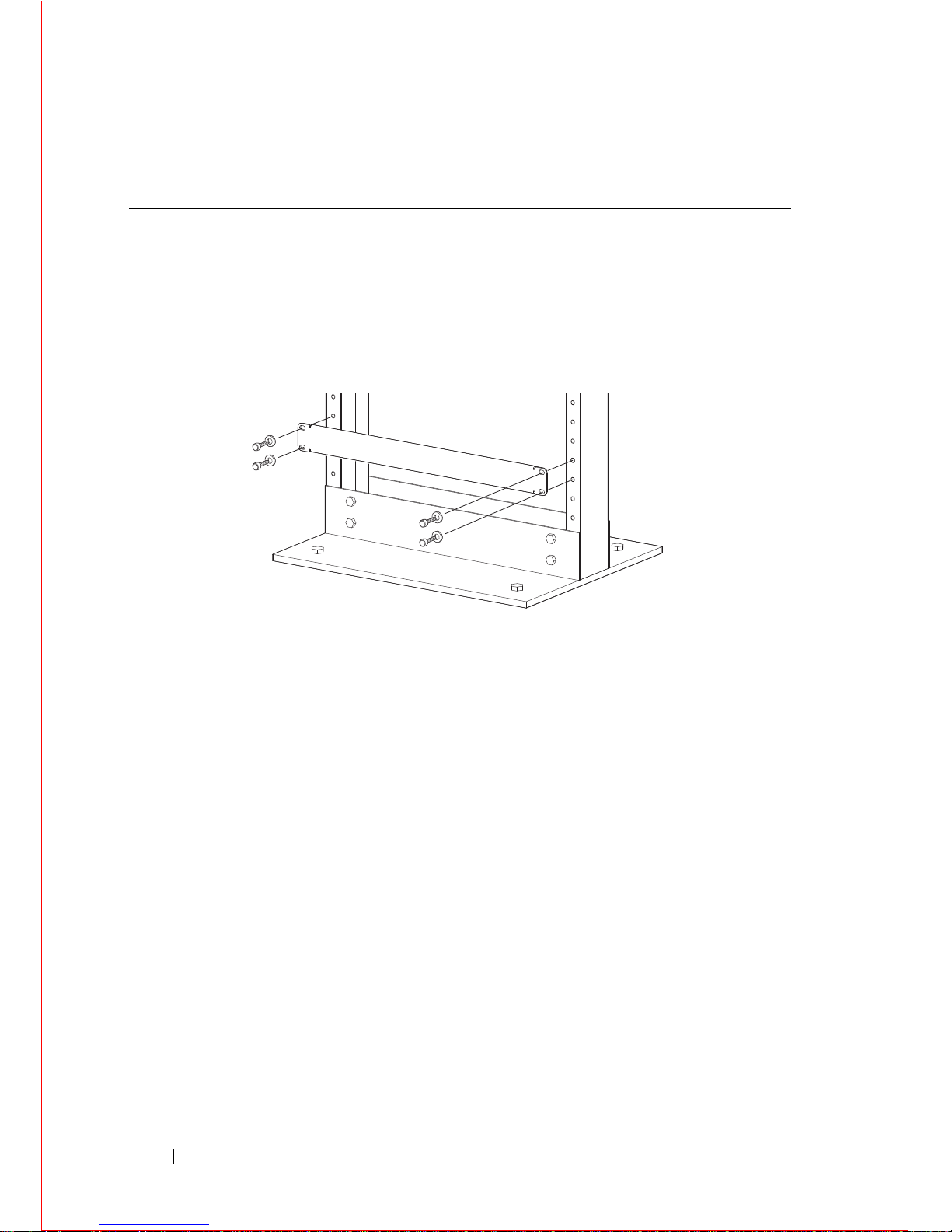
Installing the Chassis in a Two-Post Rack
WARNING: Use an equipment lift or pallet jack when lifting or moving the
chassis. Install the chassis into the rack before inserting chassis components.
Lift the C150/300 chassis only from the bottom. Lifting by the chassis shelves
or power supply openings might damage the chassis.
WARNING: T o pr event bodily injury when mounting or servicing this unit in
a rack, you must take special precautions to ensure that the system remains
stable. The following guidelines are provided to ensure your safety:
• This unit should be mounted at the bottom of the rack if it is the only unit
in the rack.
• When mounting this u ni t in a partially filled rack, load the rack from the
bottom to the top with the heaviest component at the bottom of the rack.
• If the rack is provid ed with stabilizing devices, install the stabiliz er s
before mounting or servicing the unit in the rack.
Follow these steps to install the chassis into a 19-inch equipment rack:
Page 8
6 Installing the Hardware
Step Task
1 Determine the chassis mounting location in the equipment rack.
2 Orient the bar with the arrows pointing upward. The smooth side of the
bar should face outward.
3 Attach the bar to the equipment rack brackets using the mounting screws
provided by the rack manufacturer.
4 Use an equipment lift to align the chassis rack-mount holes with the
equipment rack holes, and situate the chassis on top of the equipment
rack bar.
Page 9
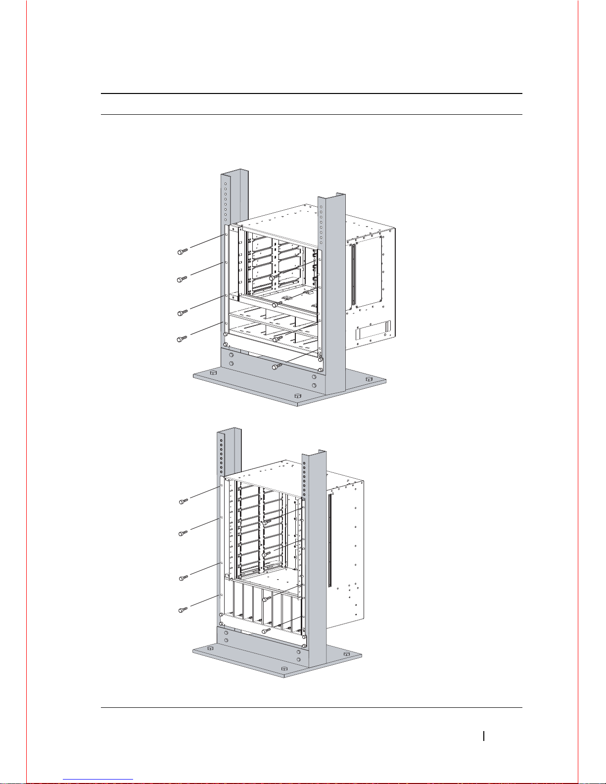
Installing the Hardware 7
5 Insert screws (provided with your rack) through the chassis rack-
mounting bracket and into the equipment rack, and tighten them.
Rack Mounting the C150 Chassis
Rack Mounting the C300 Chassis
Step Task
fnD0002mp
Page 10
8 Installing the Hardware
Attach a Ground Cable to the C150/300 DC
Chassis
WARNING: You must complete the ground connection before proceeding
with any DC PEM connection.
The AC power cord is the primary ground connection for C-Series AC chassis.
This procedure applies to the DC powered chassis only.
You must provide your own cables to connect to a remote power source (a
circuit breaker panel, for example) in your equipment rack or facility. Cables
must be sized to meet the following criteria:
• Rated for 60A service to allow for a fully loaded C150 system per NEC in the
United States or internationally, per local safety codes.
• Limit voltage drop across the cable length to 0.5V or less.
NOTE: Apply a coat of anti-oxidant paste to unplated metal contact
surfaces before you make the cable connections. File unplated connectors,
braided straps, and bus bars to a shiny finish. It is not necessary to file and
coat tinned, solder plated, or silver-plated connectors or other plated
connection surfaces, such as those on the PEM studs.
Step Task
1 Locate the chassis ground connector stud on the PEM front panel. It is
the single stud below the safety cover.
2 Remove the nut and washer from the ground stud.
3 Apply a coat of anti-oxidant paste to the connector stud, if required.
4 Install the grounding cable. This cable is typically green or green a nd
yellow.
NOTE: Termination points require UL-listed 1-hole lug with a
1/4-inch hole.
5 Replace the washer and nut on the stud.
6 Secure the nut with a nut driver or torque wrench (not to exceed 4
ft/lbs).
7 Connect the opposite end of the grounding cable to the appropriate
nearest grounding.
Page 11

Installing the Hardware 9
Installing Power Modules
NOTE: Do not mix AC and DC power supplies in the same chassi s.
If there is a failure in the power supply, it must be replaced. Power supplies are
not field serviceable.
The C150 has six power supply slots at the bottom front of the chassis. The
C300 has eight power supply slots at the front-bottom of the chassi s. The slots
accept either AC Power Supplies (PSUs) or DC Power Entry Modules (PEMs).
AC Power Supplies
• The C150 requires only one AC power supply to operate, but Dell Force10
recommends a one-plus-one redundancy configu ration, so a minimum of two
power supplies is recommended.
• The C300 requires a minimum of tw o AC power s upplies to operate, bu t Dell
Force10 recommends a two-plus-one redundancy configuration, so a
minimum of three power supplies is recommended.
• To protect against high-voltage shock, install a power supply blank on all
unused power supply slots.
• Connect the AC power supply to the appropriate branch circuit protection as
defined by local electrical codes.
• Verify that the remote power source complies with the system input power
specifications.
WARNING: Use only the AC power cord supplied with the AC power supply.
Do not supply power to your C150 system until the power supplies and fan
tray are installed, and RPMs and line cards have been installed.
WARNING: This product relies on the building's installation for short-circuit
(overcurrent) protection. Ensure that a fuse or circuit breaker no larger than
120 VAC, 15A U.S. (240 VAC, 10A international) is used on the phase
conductors (all current-carrying conductors).
WARNING: The C300 does not have a main disconnect device installed. It is
the responsibility of the installer to provide a suitable disconnecting device in
the building installation and ensure that it is located/instal le d near the
equipment and is easily accessible.
Page 12

10 Installing the Hardware
Leakage Current (High Touch Current) in AC-powered systems with more
than 3+1 power supplies. The power cord plugs must be secured to the building
outlets by the qualified chassis installer or a qualified electrician
.
WARNING: The C300 operates in either of two voltage ranges. Each range
supports a different power supply configuration. As a safety pr ecaution, do
not install more than the recommended maximum number of PSUs (given by
the table below), as this causes high leakage current. Install blank panels in all
unused PSU slots.
Installing DC Power Supplies
• The C150 requires at least one DC PEM for operation, but Dell Force10
recommends a one-plus-one redundancy configuration. Those DC PEMs are
inserted in slots 0 and 2.
• The C300 requires at least one DC PEM for operation, but Dell Force10
recommends a one-plus-one redundancy configuration. Those DC PEMs are
inserted in slots 0 and 7.
Voltage Frequency Maximum PSU
100 -110 50/60Hz 6 primary + 2 redundant
200 - 240 50/60Hz 3 primary + 1 redundant
Step Task
1 Verify the switch is in the OFF (left) position.
2 Secure the retaining latch in the unlatched position by tightening the
screw into the threaded hole.
3 Slide the power supply into the top left-most po we r supply slot.
Dell Force10 recommends installing power supplies starting from the
left side, top row of the chassis, leaving no blank slots between units.
4 Plug the AC power cord into the power receptacle in the face of the
power supply.
5 Lower the retaining latch, and tighten it into place.
6 Plug the power cord into an AC power outlet.
Page 13

Installing the Hardware 11
• To protect against high-voltage shock, install a power supp ly blank (CC-CBLNK-PWR) on all unused power supply slots.
CAUTION: Some CH-C300 chassis may require Dell For ce10 assistance when
using some DC power supplies. Please contact the Dell Force10 TAC if you
experience any difficulty during installation
Step Task
1 Turn the remote power source (the circuit breaker panel) to the OFF
position.
2 Turn the over-current switch (located on the PEM front panel) to the
OFF position.
3 Loosen the PEM safety cover retaining screw and remove the cover.
4 Slide the PEM into slots 1 and 2 (for the C150) or slots 0 and (for the
C300)
NOTE: Fill all empty slots with blank panels.
C150 Entry Module Installation
C300 Power Entry Module Installation
BLNK
fn00012lpp
fn003lp
BLNK
fn003lp
BLNKBLNK
Safety Cover
Over-Current Switch
Retaining Latch
Handle
Power Supply Blank
fn0002lp
Page 14

12 Installing the Hardware
Installing RPMs and Line Cards
The C150 system accommodates four Line Cards and two Route Processor
Modules (RPMs).
The C300 System accommodates eight line cards and two Route Processor
Modules (RPMs).
5 Secure the PEM in place by tightening the retaining latch on each
module so that the arrow points down
6 Remove the outer nuts and washers from each of the remaining studs.
7 Connect the -48 VDC and Return cables from each PEM to the remote
power sources.
a
Verify that the remote power source is in the OFF position.
b
Locate the appropriate studs on the PEM front panel.
- The two right-handed studs (furthest from the GND) are the return
(+48V DC) connection. The cable attached to these studs is typically
red.
- The two left-handed studs (closest to GND) are the -48 V DC
connection. The cable attached to these studs is typically black.
NOTE: Power cables must be terminated only with a UL-listed 2-
hole lug to accommodate 1/4-inch studs with 3/4-inch spacing.
c
Apply a coat of anti-oxidant paste to the connector studs, if re qu ired.
d
Replace the washers and nuts on the studs.
e
Route the terminated cables out toward the rack rail. Cables w ill
route down toward the floor. You can then route them as best suits
your environment.
f
Secure the nuts with a nut driver or torque w rench (not to exceed 4
ft/lbs).
8 Replace the safety cover and tighten the captive screw. The safety cover
can be rotated to accommodate system configurations.
9 Turn the Over-Current Protector to the ON position.
10 Turn the remote power source (the circuit breaker panel) to the ON
position.
Step Task
Page 15

Installing the Hardware 13
RPMs
The C-Series system requires at least one Route Processor Module (RPM); two
are recommended.
• One RPM provides 48 Gigabits of bandwidth to each line card.
• Two RPMs provides 96 Gigabits of bandwidth to each line card.
• Blanks are required in empty slots to control airflow for adequ ate sys tem
cooling, personal safety, and EMI containment during operation. All chassis
slots must be installed with operational modules or blanks. Always replace
cards and blank panels immediately.
• The blank panels for RPMs and line cards are diffe ren t sizes (RPM blanks
are smaller); be sure that blank panels are installed in the correct slots.
• RPMs are hot-swappable. High Availability is supported.
• If your system contains two RPMs, both RPMs must have the same softw are
image.
• RPMs are interchangable between the C300 and the C150 only if they are
running FTOS version 7.6.1.0 or later.
CAUTION: RPMs are designed to be installed in either the R0 or R1 slot. Do
not force RPMs into RPM or line cards slots. RPMs are keyed differently than
line cards to prevent improper installation.
Line Cards
Line cards are hot-swappable. Any line card can be inserted into any line card
slot. On the C150, line card slots are numbered 0 to 3. On the C300, Line card
slots are labeled 0 to 7. THe slot numbering labels can be seen when the fan tray
is installed.
• The LC-CB-GE-48P and LC-CB-10GE-8P line cards are interchangeable
between the C300 and C150 only if the chassis is running FTOS version
7.6.1.0 or later.
• Blanks are required in empty slots to control airflow for adequ ate sys tem
cooling, personal safety, and EMI containment during operation. All chassis
slots must be installed with operational modules or blanks. Always replace
cards and blank panels immediately.
Page 16

14 Installing the Hardware
Installing RPMs and Line Cards
WARNING: Always wear an ESD-preventive wrist or foot-heel ground strap
when handling RPMs or line cards. Place RPMs and line cards on an antistatic
surface when they ar e not instal led. Electr ostatic discharge (ESD) damage can
occur when components are mishan d led .
CAUTION: Unlock the levers before inserting the line card into the chassis.
Fully engage the locking mechanism after the card has been inserted; not
doing so might damage the card below it when that lower card is inser t ed .
NOTE: The fan tray face panel has slot number markings for the RPMs and line
cards. Insert the fan tray before the line cards to simplify RPM and line card
installation.
Step Task
1 Extend the left and right card levers by first pressing gently down on the
thumb tabs in the ejector levers and then pulling the ejector levers
simultaneously until they are in the open position.
2 Hold the card assembly by the metal carrier edges. Avoid touching the
printed circuit board and connector pins.
3 Align the card with the guide, and gently slide it into any line ca rd slot
until the card is about halfway into the slot.
NOTE: Use the markings on the fan tray to determine whic h slots
are for the RPMs and which are for the line cards.
4 Continue sliding the card until you feel the connectors engage with the
chassis backplane.
5 Rotate the levers toward the card to seat the backplane connectors and
line card in place. Push on the knurled section of the levers until the
thumb tabs pop up and lock the unit in place.
CAUTION: Installing a card without fully engaging the
locking mechanism might damage the EMI seal on the card
below it when that card is inserted.
6 Install a blank panel in all slots th at do not have a card, and secure it
with the screws provided.
Page 17

Installing the Hardware 15
Installing the Fan Tray
The C-Series chassis contains one field-replaceable fan tray . There are two types
of fan tray that may be installed: one contains six fans that run at varying speeds
depending on system temperature; the other one cont ains six fans th at run at a
constant speed. For both types of trays, air flows through the system toward the
fans (right to left) and is exhausted on fan-side of the chassis. The fan tray is
accessible from the front of the chassis.
WARNING: To ensure proper temperature and airflow control, the fan tray
must always be installed and operating properly.
NOTE: The system does not have an air filter so take special care in making sure
that the installation site and the chassis itself are cleaned regularly.
C150
Step Task
1 Slide the fan tray into the fan slot.
2 Gently push on the front of the tray until it stops. The fan tray should be
flush with the chassis.
3 Use a #2 Phillips screwdriver to secure the fan tray into place by
tightening the screws at the top and bottom of the fan tray.
fnD0003mp
0
1
2
3
R0
R1
Page 18

16 Installing the Hardware
C300
NOTE: The fan tray LED will remain lit when the chassis is powered up and the
fan tray is functioning properly.
Power Up Sequence
Before you supply power to the chassis, Dell Force10 recommends that you reinspect your equipment rack and chassis.
CAUTION: Never operate the system without a fan tray.
CAUTION: The C300 operates in either of two voltage ranges. Each range
supports a different supply configuration. As a safety precaution, do not
install more than the recommended maximum number of power supplies
(given by the table below), as this causes high leakage current. Install blank
panels in all unused power supply slots.
To supply power to the system:
Step Task
1 Verify that the power source complies with the system input power
requirements.
2 Energize the remote power source or outlet.
fnC0003mp
7
6
5
4
0
1
2
3
R0
R1
7
6
5
4
0
1
2
3
R0
R1
Page 19

Installing the Hardware 17
After you supply power to the system, the following should occur:
• The fan tray should be operating.
• The green (online) fan tray, RPM, and line card LEDs should be lit and
remain lit as long as the system is receiving power and is operational.
When you supply power to the chassis, the system performs a series of power-on
self tests. RPM and line card LEDs blink as the diagnostic programs run. No
user interaction is required at this point. Observe the process on your console
monitor. When the boot process is complete, the card LEDs remain online
(green) and the console monitor displays the Command Line Interface (CLI)
prompt.
3 On the C150, toggle the switch on the AC power supplies to the ON
(right) position.
On the C300, toggle the switch on the AC power supplies to the ON
(top) position.
On either system, toggle the switch on the DC power Over -Current
Protector ON
4 The power supply LEDs should be green. If these LEDs are not lit
green:
• Check that the unit is properly installed.
• Verify the power source.
• If the power supply cannot be verified, pow e r off all modules and
replace the unit.
5 The fan tray LED should be green (online). You should be able to hear
the air flowing through the chassis. If the fans are not operating properly
or air is not flowing through the chassis:
• Power off all power supp lies .
• Verify that the fan tray is properly installed.
• If the fan tray LED remains unlit, power dow n the unit, and replace the
fan tray.
Step Task
Page 20

18 Installing the Hardware
Specifications
Chassis Physical Design
Environmental Parameters
AC Power Requirements
Parameter C150 Specifications C300 Specifications
Height 15.7 inches (39.88 cm) 22.7 inches (57.66 cm)
Width 17.5 inches (44.45 cm) 17.4 inches (37.58 cm)
Depth 15.3 inches (38.86 cm) 14.4 inches (44.20 cm)
Chassis weight 38 lbs (17.24 kg) with factory
installed components
86.63 lbs (39.29 kg) fully
loaded
55 lbs (24.95 kg) with factory
installed components
152.27 lbs (69.07 kg) fully
loaded
Parameter C150 Specifications C300 Specifications
Temperature 41° to 104°F (5°C to 40°C)
(storage temperature)
41° to 104°F (5°C to 40°C)
(storage temperature)
Maximum thermal
output
24,566 BTU/hour (for
100/120V and 200/240V)
4095 BTU/hour (for 100/120V
and 200/240V)
Relative humidity 5 to 95% (non-condensing) 5 to 95% (non-condensing)
Parameter C150 Specifications C300 Specifications
Nominal input voltage 100 - 240 V 50/60 Hz 100-240 VAC 50/60 Hz
Maximum AC Power
Supply Input Current
(Based on 1200 W
output for 100/120 V
and 200/240 V lines.)
14 A @ 100 V per AC Power
Supply
12 A @ 120 V per AC Power
Supply
7 A @ 200 V per AC Power
Supply
6 A @ 240 V per AC Power
Supply
14 A @ 100 V per AC Power
Supply
12 A @ 120 VAC per AC
Power Supply
7 A @ 200 VAC per AC Power
Supply
6 A @ 240 VAC per AC Power
Supply
Maximum System
Power Input
4.5 KVA @ 100/120 V
4.4 KVA @ 200/240 V
8.7 KVA @ 100/120 V
8.5 KVA @ 200/240 V
Page 21

Installing the Hardware 19
DC Power Requirements
Maximum power
consumption
4,420 W @ 100/120 V
4,319 W @ 200/240 V
8,675 W @ 100/120 V
8,476 W @ 200/240 V
Maximum Thermal
Output at 100/120 V
2,921 BTU/hour (856 W) 4,978 BTU/hour
Maximum Thermal
Output at 200/220 V
2,850 BTU/hour (835 W) 4.864 BTU/hour
Parameter C150 Specifications C300 Specifications
Nominal input voltage -44 to -55 V -44 to -55 V
Maximum Current
Draw (per DC PEM)
32 A per DC PEM 32 A per DC PEM
Maximum system
power consumption
800 W 1,460 W
Maximum Thermal
Output
2,457 BTU/hour (720 W) 4,231 BTU/hour (1,240 W)
Parameter C150 Specifications C300 Specifications
Page 22

20 Installing the Hardware
Page 23

Installing the Software 21
2
Installing the Software
Navigating CLI Modes
The FTOS prompt changes to indicate the CLI mode. You must move linearly
through the command modes, with the exception of the end command which
takes you directly to EXEC Privilege mode; the exit command moves you up
one command mode level.
Console Access
The console port is an asynchronous serial port. If you connect a device to these
ports, it must be capable of asynchronous transmission.
Step Task
1 Install an RJ-45 copper cable into the console port. Use a rollover cable to
connect the C150 or C300 console port to a terminal server.
2 Connect the other end of the cable to the DTE terminal server.
3 You r termin al or terminal emulation mode must be set to VT100 with
the following settings:
9600 baud rate (To avoid autobaud input, the default is set to a 9600 BPS.)
No parity
8 data bits
1 stop bit
Window Terminal Emulator option set to NO
24 lines X 80 characters
No flow control
Page 24

22 Installing the Software
Cable and Adapter Pin Assignments
Use the console port on the RPM of the C150 or C300 to connect to a terminal
port, PC serial port, or a terminal server to configure and monitor your system.
An RJ-45 Ethernet cable is required to connect to the Ethernet port.
The console port is an RJ-45 and the pinouts are listed in Table 2-1.
Accessing the Console with a DB-9 Adapter
You can connect to the console using an RJ-45 to RJ-45 rollover cable and an
RJ-45 to DB-9 female DTE adapter (labeled “TERMINAL”) to a terminal
server (for example, PC).
Table 2-1. Pin Assignments for Console Port (RJ-45)
Pin Signal Input/Output
1 NC (unused 2 DTR Output
3 TxD Output
4GND5GND6 RxD Input
7DSRInput
8 NC (unused -
Table 2-2. Pin Assignments Between the Console and a DTE Terminal Server
Console Port RJ-45 to RJ-45 Rollover Cable RJ-45 to DB-9
Adapter
Terminal
Server Device
Signal RJ-45 Pinout RJ-45 Pinout DB-9 Pin Signal
RTS 1 8 8 CTS
DTR 2 7 6 DSR
TxD 3 6 2 RxD
GND 4 5 5 GND
Page 25

Installing the Software 23
Accessing the Console with a DB-25 Adapter
You can connect to the console port using an RJ-45 to RJ-45 rollover cabl e and
an RJ-45 to a DB-25 female DTE adapter.
GND 5 4 5 GND
RxD633TxD
DSR 7 2 4 DTR
CTS817RTS
Table 2-3. Pin Assignments Between the Console and a DTE Terminal Server
Console Port RJ-45 to RJ-45 Rollover Cable RJ-45 to DB-25
Modem Adapter
Terminal
Server Device
Signal RJ-45 Pinout RJ-45 Pinout DB-25 Pinout Signal
RTS 1 8 5 CTS
DTR 2 7 6 DSR
TxD 3 6 3 RxD
GND 4 5 7 GND
GND 5 4 7 GND
RxD 6 3 2 TxD
DSR 7 2 20 DTR
CTS 8 1 RTS
Table 2-2. Pin Assignments Between the Console and a DTE Terminal Server
Console Port RJ-45 to RJ-45 Rollover Cable RJ-45 to DB-9
Adapter
Terminal
Server Device
Signal RJ-45 Pinout RJ-45 Pinout DB-9 Pin Signal
Page 26

24 Installing the Software
Default Configuration
A version of the Dell Force10 Operating System (FTOS) is pre-loaded onto the
chassis, however the system is not configured when you power up for the first
time (except for the default host na me, which is Force10). You must co nfigure
the system using the Command Line Interface (CLI).
Configure Layer 2 (Data Link) Mode
Use the switchport command in INTERFACE mode to enable Layer 2 data
transmissions through an individual interface. The user cannot configure
switching or Layer 2 protocols such as the spanning tree protocol on an interface
unless the interface has been set to Layer 2 mode.
To view the interfaces in Layer 2 mode, use the show interfaces switchport
command in the EXEC mode.
Configure a Host Name
The host name appears in the prompt. The default host name is force10.
• Host names must start with a letter and end with a letter or digit.
• Characters within the string can be letters, digits, and hyphens.
Access the System Remotely
You can configure the system to access it remotely by Telnet.
Step Task Command Syntax Command Mode
1 Enable the interface. no shutdown INTERFACE
2 Place the interface in
Layer 2 (switching)
mode.
switchport INTERFACE
Task Command Syntax Command Mode
Create a new host name. hostname name CONFIGURATION
Page 27

Installing the Software 25
The C150 and C300 systems have a dedicated management port and a
management routing table that is separate from the IP routing table.
Configuring the system for Tel net is a three-step process:
Configure the Management Port IP Address
Assign IP addresses to the management ports in order to access the system
remotely.
NOTE: Assign different IP addresses to each RPM’s management port.
Configure a Management Route
Define a path from the system to the network from which you are accessing the
system remotely. Management routes are separate from IP routes and are only
used to manage the system through the management port.
Step Task
1 Configure an IP address for the management port.
2 Configure a management route with a default gateway.
3 Configure a username and password.
Step Task Command Syntax Command Mode
1 Enter INTERFACE
mode for the
Management port.
interface ManagementEthernet
slot/port
CONFIGURATION
2 Assign an IPv4 or
IPv6 address to the
interface.
ip address {ipv4-address | ipv6-
address}/mask
INTERFACE
3 Enable the interface. no shutdown INTERFACE
Page 28

26 Installing the Software
Configure a Username and Password
Configure a system username and password to access the system remotely.
Configure the Enable Password
The EXEC Privilege mode is accessed by the enable command. Configure a
password as a basic security measure. When using a console connection, EXEC
Privilege mode is unrestricted by default; it cannot be reached by a VTY
connection if no password is configured. There are two types of enable
passwords:
• enable password stores the password in the running/startup configuration
using a DES encryption method.
• enable secret is stored in the running/startup configuration by using a
stronger, MD5 encryption method.
Dell Force10 recommends using the enable secret password.
Task Command Syntax Command Mode
Configure an IPv4 or IPv6
management route to the
network from which you
are accessing the system.
management route {ipv4-address
| ipv6-address}/mask gateway
CONFIGURATION
Task Command Syntax Command Mode
Configure a username
and password to
access the system
remotely.
username username password
[encryption-type] password
CONFIGURATION
Task Command Syntax Command Mode
Create a password to
access EXEC
Privilege mode.
enable [password | secret] [level level]
[encryption-type] password
CONFIGURATION
Page 29

Installing the Software 27
Create a VLAN
The Default VLAN is part of the system startup configuration, and is by default,
VLAN 1. You may make another VLAN the Default VLAN. The Default
VLAN cannot be deleted, disabled, or configured (you cannot assign it an IP
address), and only untagged interfaces can belong to it.
When an interface is configured, a switchport automatically places it in the
default VLAN as an untagged interface. All switchports must belong to at least
one VLAN, so to remove a switchport from the Default VLAN, you must place
it as tagged or untagged in some other VLAN, or remove the switchport
configuration.
Assign Interfaces to a VLAN
A port may either be an untagged member of a single VLAN, or a tagged
member of perhaps multiple VLANs.
• Untagged Ports — ports that do not append an 802.1Q VLAN tag to fram es
on egress, and do not accept tagged frames on ingre ss (tagged frames are
dropped). Untagged ports must be connected to VLAN-u naware devices.
• Tagged Ports — ports that append an 802.1Q tag to frames on egress, and
accept only tagged frames on ingres s (untag ged frame s are dropped). Tagged
ports must be connected to VLAN-aware devices.
When you configure an enabled port as a switchport, the port is placed in the
default VLAN. To remove a switchport from the default VLAN, remove the
switchport configuration. To move the port to another VLAN, add it to the
desired VLAN as either a tagged or untagged member.
To view just the interfaces that are in Layer 2 mode, enter the show interfaces
switchport command in the EXEC mode.
Task Command Syntax Command Mode
Create a VLAN interface vlan vlan-id CONFIGURATION
Display all VLANs. show vlan vlan-id EXEC Privilege
Page 30

28 Installing the Software
Assign an IP address to a VLAN
NOTE: An IP address cannot be assigned to the Default VLAN, wh ich, by default,
is VLAN 1. To assign another VLAN ID to the Default VLAN, use the default
vlan-id vlan-id command.
Connecting the Chassis to the Network
Once you have completed the hardware installation and software configuration,
you can connect to your company network by following your company’s cabling
requirements.
Step Task Command Syntax Command Mode
1 Assign a switchport to a
VLAN.
[tagged | untagged] interface INTERFACE VLAN
2 Display all switchports
and the VLANs of which
they are members.
show vlan EXEC Privilege
Task Command Syntax Command Mode
Configure an IP address and mask on
the interface.
ip address ip-address
mask [secondary]
INTERFACE
Page 31

Page 32

www.dell.com | support.dell.com
Printed in the U.S.A.
 Loading...