

Dell EMC DSS 9620 Installation And Service Manual

Dell EMC DSS 9620 Servers
Installation and Service Manual
Regulatory Model: B09B
Regulatory Type: B09B002

Notes, cautions, and warnings
NOTE: A NOTE indicates important information that helps you make better use of your product.
CAUTION: A CAUTION indicates either potential damage to hardware or loss of data and tells you how to avoid the problem.
WARNING: A WARNING indicates a potential for property damage, personal injury, or death.
© 2018 Dell Inc. or its subsidiaries. All rights reserved. Dell, EMC, and other trademarks are trademarks of Dell Inc. or its subsidiaries. Other trademarks
may be trademarks of their respective owners.
2018 - 11
Rev. A01

Contents
1 Overview........................................................................................................................................................ 7
2.5-inch half-width server.................................................................................................................................................7
3.5-inch half-width server.................................................................................................................................................8
System specications........................................................................................................................................................9
Front-panel features.........................................................................................................................................................10
Diagnostic indicators........................................................................................................................................................10
NIC indicator codes....................................................................................................................................................10
HDD Indicator codes...................................................................................................................................................11
Locating your system service tag....................................................................................................................................11
2 Documentation resources.............................................................................................................................12
3 Technical specications................................................................................................................................15
Processor specications..................................................................................................................................................15
System battery specications.........................................................................................................................................15
Expansion bus specications...........................................................................................................................................15
Memory specications.....................................................................................................................................................15
Ports and connector specications................................................................................................................................16
USB ports.................................................................................................................................................................... 16
NIC ports..................................................................................................................................................................... 16
DisplayPort...................................................................................................................................................................16
Environmental specications...........................................................................................................................................16
Temperature specications........................................................................................................................................17
Relative humidity specications................................................................................................................................17
Maximum vibration specications.............................................................................................................................17
Maximum shock specications................................................................................................................................. 17
Maximum altitude specications...............................................................................................................................18
Operating temperature de-rating specications.....................................................................................................18
Particulate and gaseous contamination specications...........................................................................................18
Standard operating temperature specications......................................................................................................19
Expanded operating temperature specications.................................................................................................... 19
Expanded operating temperature restrictions........................................................................................................20
4 Initial system setup and conguration...........................................................................................................21
Setting up your system....................................................................................................................................................21
Setting up your system....................................................................................................................................................21
iDRAC conguration.........................................................................................................................................................21
Options to set up iDRAC IP address........................................................................................................................22
Log in to iDRAC..........................................................................................................................................................22
Options to install the operating system.........................................................................................................................23
Methods to download rmware and drivers...........................................................................................................23
Downloading drivers and rmware...........................................................................................................................23
Contents
3

5 Pre-operating system management applications..........................................................................................25
Options to manage the pre-operating system applications........................................................................................25
System Setup...................................................................................................................................................................25
Viewing System Setup.............................................................................................................................................. 25
System Setup details.................................................................................................................................................26
System BIOS.............................................................................................................................................................. 26
iDRAC Settings utility................................................................................................................................................46
Dell Lifecycle Controller.............................................................................................................................................47
Boot Manager.............................................................................................................................................................48
PXE boot.....................................................................................................................................................................49
6 Installing and removing server components................................................................................................. 50
Safety instructions...........................................................................................................................................................50
Before working inside your system................................................................................................................................50
After working inside your system...................................................................................................................................50
Recommended tools.........................................................................................................................................................51
System memory................................................................................................................................................................51
General memory module installation guidelines.......................................................................................................51
Mode-specic guidelines.......................................................................................................................................... 52
Memory optimized (independent channel) mode..................................................................................................52
Memory sparing......................................................................................................................................................... 52
Memory mirroring...................................................................................................................................................... 52
Sample memory congurations................................................................................................................................53
Removing memory module.......................................................................................................................................54
Installing memory module......................................................................................................................................... 58
Processor and heat sink..................................................................................................................................................62
Removing heat sink................................................................................................................................................... 62
Removing processor..................................................................................................................................................64
Installing processor....................................................................................................................................................65
Installing heat sink......................................................................................................................................................66
Expansion card and riser..................................................................................................................................................71
Expansion card installation guidelines.......................................................................................................................71
Removing expansion card from slot 1.......................................................................................................................71
Installing expansion card into slot 1.......................................................................................................................... 72
Removing expansion card from slot 3..................................................................................................................... 72
Installing expansion card into slot 3..........................................................................................................................72
Removing expansion card from slot 4..................................................................................................................... 72
Installing expansion card into slot 4..........................................................................................................................73
Removing expansion card from slot 5..................................................................................................................... 73
Installing expansion card into slot 5......................................................................................................................... 73
Removing expansion card from slot 6..................................................................................................................... 73
Installing expansion card into slot 6..........................................................................................................................74
System battery................................................................................................................................................................. 74
Removing system battery......................................................................................................................................... 74
Installing system battery............................................................................................................................................76
4
Contents

Hot swappable HDD cages.............................................................................................................................................78
Installing hot swappable HDD cage..........................................................................................................................78
Removing hot swappable HDD cage.......................................................................................................................82
Hard drive..........................................................................................................................................................................84
Removing 2.5-inch hard drive from the rear bay...................................................................................................84
Installing 2.5-inch hard drive into the rear bay........................................................................................................87
Removing 3.5-inch hard drive from the rear bay...................................................................................................89
Installing 3.5-inch hard drive in the rear bay...........................................................................................................95
Removing hot swappable hard drive.......................................................................................................................101
Installing hot swappable hard drive........................................................................................................................105
Server board................................................................................................................................................................... 109
Removing server board............................................................................................................................................109
Installing server board................................................................................................................................................111
Trusted platform module................................................................................................................................................ 112
Installing trusted platform module...........................................................................................................................113
Initializing TPM for BitLocker users........................................................................................................................ 116
Initializing TPM for TXT users................................................................................................................................. 116
Restoring the Service Tag by using the Easy Restore feature............................................................................ 116
Mini PERC battery...........................................................................................................................................................117
Removing Mini PERC battery..................................................................................................................................117
Installing Mini PERC battery....................................................................................................................................119
Supercap.......................................................................................................................................................................... 121
Removing Microsemi supercap................................................................................................................................121
Installing Microsemi supercap................................................................................................................................. 123
Removing Broadcom supercap............................................................................................................................... 127
Installing Broadcom supercap................................................................................................................................. 129
Mezzanine card and Mini PERC...................................................................................................................................132
Removing mezzanine card...................................................................................................................................... 132
Installing mezzanine card.........................................................................................................................................138
Removing Mini PERC...............................................................................................................................................144
Installing Mini PERC.................................................................................................................................................146
M.2 SSD.......................................................................................................................................................................... 149
Removing x8 PCIe M.2 card................................................................................................................................... 149
Installing x8 PCIe M.2 card......................................................................................................................................155
Removing x8 SATA M.2 card..................................................................................................................................159
Installing x8 SATA M.2 card.....................................................................................................................................166
Removing x16 PCIe M.2 card..................................................................................................................................172
Installing x16 PCIe M.2 card.................................................................................................................................... 178
Removing x16 SATA M.2 card.................................................................................................................................184
Installing x16 SATA M.2 card...................................................................................................................................190
PCIe card.........................................................................................................................................................................196
Removing PCIe card................................................................................................................................................ 196
Installing PCIe card..................................................................................................................................................202
OCP card........................................................................................................................................................................208
Removing OCP card from slot 1.............................................................................................................................208
Contents
5

Installing OCP card into slot 1..................................................................................................................................214
Removing OCP card from slot 3............................................................................................................................222
Installing OCP card into slot 3................................................................................................................................226
3M riser card..................................................................................................................................................................230
Removing 3M riser card..........................................................................................................................................230
Installing 3M riser card............................................................................................................................................238
NPIO card....................................................................................................................................................................... 246
Removing NPIO card from the rear bay................................................................................................................246
Installing NPIO card in the rear bay....................................................................................................................... 252
Removing NPIO card from hot swappable bay....................................................................................................256
Installing NPIO card in hot swappable bay............................................................................................................262
NPDB.............................................................................................................................................................................. 264
Removing NPDB......................................................................................................................................................264
Installing NPDB........................................................................................................................................................ 266
NVMe riser......................................................................................................................................................................270
Removing NVMe riser............................................................................................................................................. 270
Installing NVMe riser................................................................................................................................................274
Hard drive backplane.....................................................................................................................................................278
Removing HDD backplane...................................................................................................................................... 278
Installing HDD backplane........................................................................................................................................ 280
7 Using system diagnostics...........................................................................................................................283
Dell Embedded System Diagnostics............................................................................................................................283
Running the Embedded System Diagnostics from Boot Manager....................................................................283
Running Embedded System Diagnostics from Lifecycle Controller.................................................................. 283
System diagnostic controls.....................................................................................................................................284
8 Jumpers and connectors............................................................................................................................285
9 Troubleshooting your system......................................................................................................................287
Troubleshooting list........................................................................................................................................................ 287
10 Getting help............................................................................................................................................. 288
Contacting Dell...............................................................................................................................................................288
Documentation feedback..............................................................................................................................................288
6
Contents
Overview
The DSS 9620 server contains a full-width chassis supporting the Intel® Xeon® Scalable platform. Each server supports up to two Intel
®
Xeon® Scalable processors.
NOTE: The product at time delivery may dier from the following illustrations.
Topics:
• 2.5-inch half-width server
• 3.5-inch half-width server
• System specications
• Front-panel features
• Diagnostic indicators
• Locating your system service tag
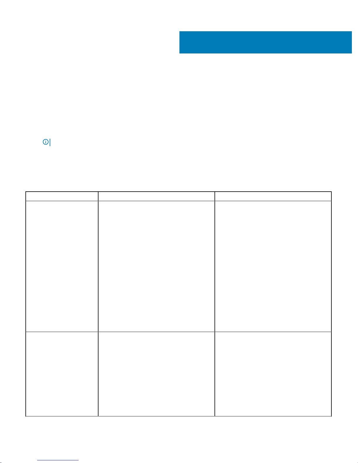
2.5-inch half-width server
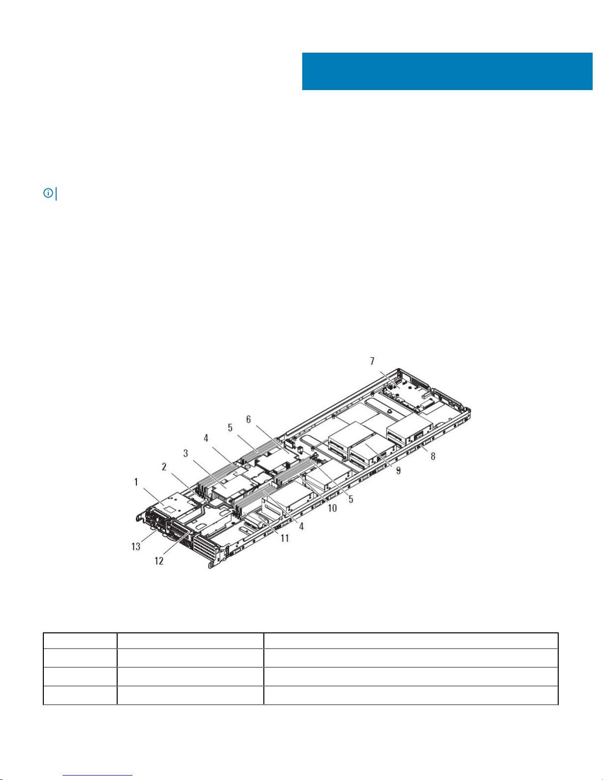
Figure 1. DSS 9620 2.5-inch half-width server
Table 1. DSS 9620 2.5-inch features
No. Item Description
1 Expansion port, slot 1 Supports x8 mezzanine expansion cards, connected to CPU 1.
2 Server board Server board (DSS 9600M) with DDR4 DIMM slots.
3 CPU heat sink 1 Heat sink for CPU 1.
1
Overview 7
No. Item Description
4 CPU 1 DIMMs Memory modules for CPU 1. For more information, see System memory.
5 CPU 2 DIMMs Memory modules for CPU 2. For more information, see System memory.
6 CPU heat sink 2 Heat sink for CPU 2.
7 NPDB Node power distribution board.
8 HW server chassis Half-width server chassis for DSS 9620 server.
9 Server rear bay Supports installation of up to ten 2.5-inch HDDs (HDD0—HDD9)
10 Expansion port, slot 5 Supports x16 PCIe expansion risers, connected to CPU 2.
11 Supercap Supercap and holder for PCIe RAID card (Microsemi and Broadcom).
12 Expansion port, slot 4 Supports x16 PCIe expansion risers, connected to CPU 1.
13 Expansion port, slot 3 Supports x8 OCP expansion cards, connected to CPU 1.
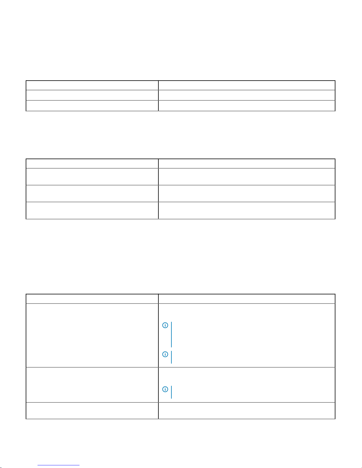
3.5-inch half-width server
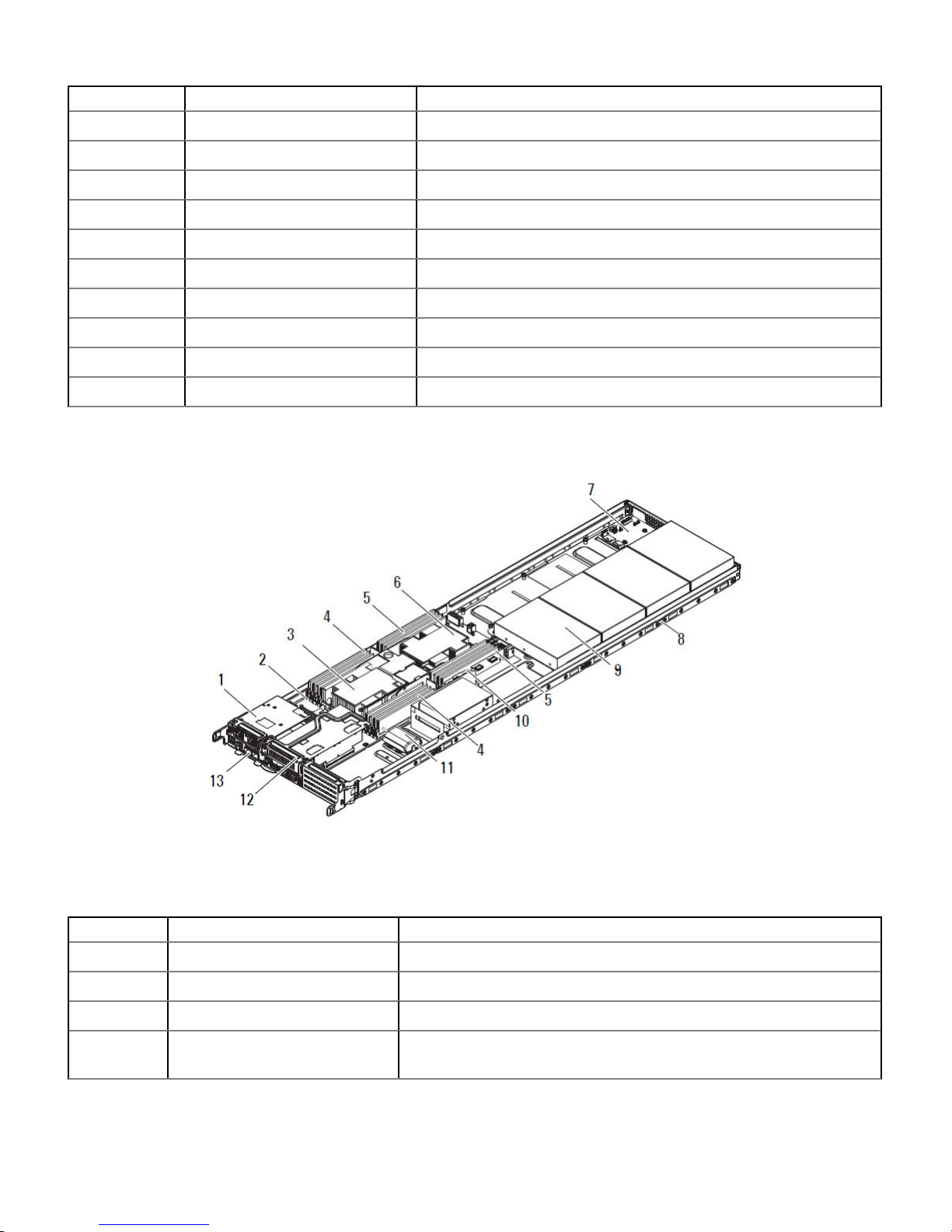
Figure 2. DSS 9620 3.5-inch half-width server
Table 2. DSS 9620 3.5-inch features
No. Item Description
1 Expansion port, slot 1 Supports x8 mezzanine expansion cards, connected to CPU 1.
2 Server board Server board (DSS 9600M) with DDR4 DIMM slots.
3 CPU heat sink 1 Heat sink for CPU 1.
4 CPU 1 DIMMs Memory modules for CPU 1. For more information about memory modules, see
System memory.
8 Overview
No. Item Description
5 CPU 2 DIMMs Memory modules for CPU 2. For more information about memory modules, see
System memory.
6 CPU heat sink 2 Heat sink for CPU 2.
7 NPDB Node power distribution board.
8 HW server chassis Half-width server chassis for DSS 9620 server.
9 Server rear bay Supports installation of up to four 3.5-inch (HDD0—HDD3) and two 2.5-inch
SSDs (SSD0—SSD1).
10 Expansion port, slot 5 Supports x16 PCIe risers, directly connected to CPU 2.
11 Supercap Supercap and holder for PCIe RAID card (Microsemi and Broadcom).
12 Expansion port, slot 4 Supports x16 PCIe risers, connected to CPU 1.
13 Expansion port, slot 3 Supports x8 OCP expansion cards, connected to CPU 1.
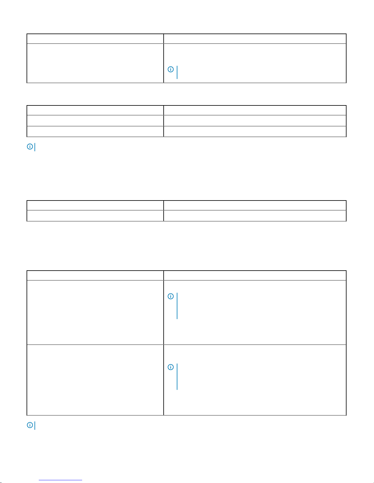
System specications
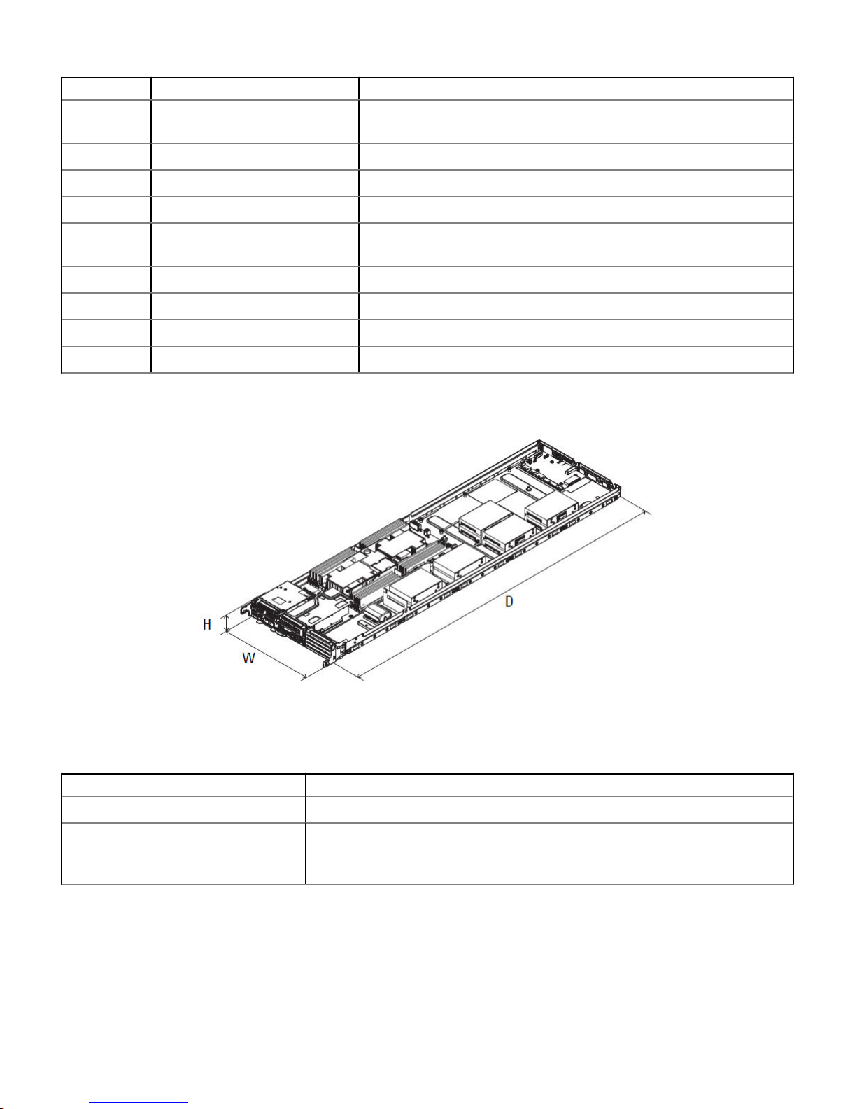
Figure 3. DSS 9620 dimensions
Table 3. DSS 9620 dimensions
Item Description
Dimension (W x D x H) 262.20 mm x 930 mm x 47 mm (10.32 inch x 36.61 inch x 1.85 inch)
Weight
2.5-inch (fully loaded): 9.8 kg (21.60 lb)
3.5-inch (fully loaded): 10.17 kg (22.42 lb)
Overview 9

Front-panel features
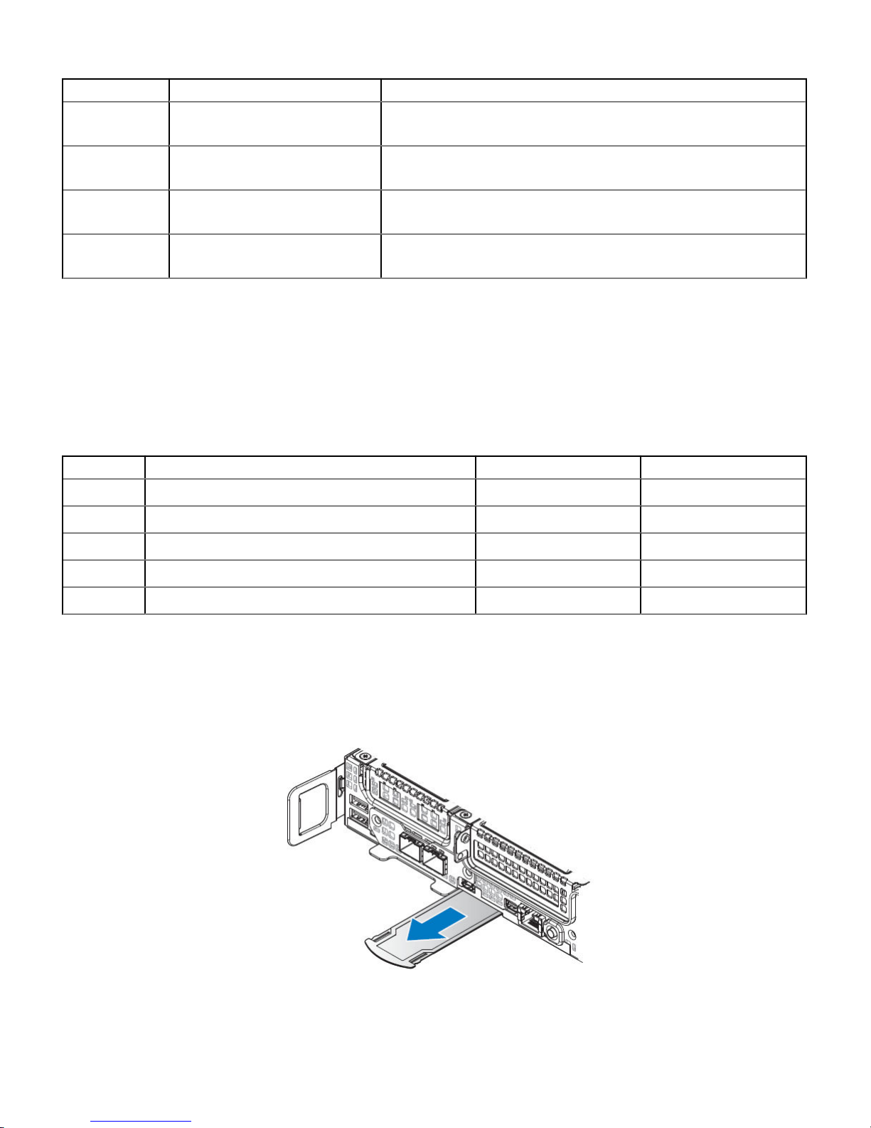
Figure 4. Front-panel features
Table 4. Front-panel features
No. Item Description
1 Expansion port, slot 1 Supports x8 mezzanine expansion cards. Connected to CPU 1.
2 Expansion port, slot 4 Supports x16 PCIe cards. Connected to CPU 1.
3 2.5-inch HDD Two 2.5-inch hot swappable HDDs.
4 Power button Press the power button to turn the server on or o. The indicator on the
button indicates if the system is on or o.
5 LAN port Single 10/100/1000 Mbps RJ-45 connector shared between 1G LAN and
iDRAC management LAN.
6 DisplayPort Single mini DisplayPort connector.
7 Service tag Location of information tag specifying the system Service Tag.
8 iDRAC Direct micro USB port The iDRAC Direct micro USB port enables you to connect a portable device
to the server.
9 Expansion port, slot 3 Supports OCP expansion cards. Connected to CPU 1.
10 USB port Two USB 3.0 compliant ports.
Diagnostic indicators
NIC indicator codes
Each NIC on the back panel has an indicator that provides information about the network activity and link status. The activity LED indicates
whether data is owing through NIC or not. The link LED indicates the speed of the connected network.
Table 5. NIC indicators
Convention Status Condition
A Link and activity indicators are o The NIC is not connected to the network.
B Link indicator is green and activity
indicator is blinking green
The NIC is connected to a valid network at its maximum port speed and data
is being sent or received.
10 Overview
Convention Status Condition
C Link indicator is amber and activity
indicator is blinking green
The NIC is connected to a valid network at less than its maximum port speed
and data is being sent or received.
D Link indicator is green and activity
indicator is o
The NIC is connected to a valid network at its maximum port speed and data
is not being sent or received.
E Link indicator is amber and activity
indicator is o
The NIC is connected to a valid network at less than its maximum port speed
and data is not being sent or received.
F Link indicator is blinking green and
activity is o
NIC identify is enabled through the NIC conguration utility.
HDD Indicator codes
The expansion adapter has LED headers that correspond to access activity and link status.
PERC H330 Mini Mono, PERC H730P Mini Mono, PERC H730 and Broadcom 9361-8i
Table 6. PERC H330 Mini Mono, PERC H730P Mini Mono, PERC H730 and Broadcom 9361-8i
LED state HDD state Green LED Amber LED
1 Empty O O
2 Online On O
3 Identify/Prepare for removal Blinking O
4 Rebuild Blinking O
5 Fault O Blinking
Locating your system service tag
Your system is identied by a unique Express Service Code and Service Tag number. The Express Service Code and Service Tag are found
on the front of the system by pulling out the information tag. Alternatively, the information may be on a sticker on the chassis of the
system. This information is used by Dell to route support calls to the appropriate personnel.
Figure 5. Service Tag location
Overview
11
Documentation resources
This section provides information about the documentation resources for your system.
To view the document that is listed in the documentation resources table:
• From the Dell EMC support site:
a Click the documentation link that is provided in the Location column in the table.
b Click the required product or product version.
NOTE: To locate the product name and model, see the front of your system.
c On the Product Support page, click Manuals & documents.
• Using search engines:
– Type the name and version of the document in the search box.
Table 7. Additional documentation resources for your system
Task Document Location
Setting up your system
For more information about installing and securing
the system into a rack, see the Rail Installation
Guide included with your rack solution.
For information about installing the system into a
rack, see the Rack documentation included with
your rack solution or the Getting Started Guide
document that is shipped with your system.
For information about installing the system into a
rack, see the Rack documentation included with
the Getting Started With Your System document
that is shipped with your system.
For information about installing the system into the
enclosure, see the Getting Started Guide
document that is shipped with your system.
For information about setting up your system, see
the Getting Started Guide document that is
shipped with your system.
Dell.com/dssmanuals
Dell.com/poweredgemanuals
Conguring your system For information about the iDRAC features,
conguring and logging in to iDRAC, and managing
your system remotely, see the Integrated Dell
Remote Access Controller User's Guide.
For information about understanding Remote
Access Controller Admin (RACADM)
subcommands and supported RACADM interfaces,
see the RACADM CLI Guide for iDRAC.
For information about Redsh and its protocol,
supported schema, and Redsh Eventing
implemented in iDRAC, see the Redsh API Guide.
Dell.com/poweredgemanuals
2
12 Documentation resources

Task Document Location
For information about iDRAC property database
group and object descriptions, see the Attribute
Registry Guide.
For information about Intel QuickAssist Technology,
see the Integrated Dell Remote Access Controller
User's Guide.
For information about earlier versions of the iDRAC
documents.
To identify the version of iDRAC available on your
system, on the iDRAC web interface, click ? >
About.
Dell.com/idracmanuals
For information about installing the operating
system, see the operating system documentation.
Dell.com/operatingsystemmanuals
For information about updating drivers and
rmware, see the Methods to download rmware
and drivers section in this document.
Dell.com/support/drivers
Managing your system For information about systems management
software oered by Dell, see the Dell OpenManage
Systems Management Overview Guide.
Dell.com/poweredgemanuals
For information about setting up, using, and
troubleshooting OpenManage, see the Dell
OpenManage Server Administrator User’s Guide.
Dell.com/openmanagemanuals > OpenManage
Server Administrator
For information about installing, using, and
troubleshooting Dell OpenManage Essentials, see
the Dell OpenManage Essentials User’s Guide.
Dell.com/openmanagemanuals > OpenManage
Essentials
For information about installing and using Dell
SupportAssist, see the Dell EMC SupportAssist
Enterprise User’s Guide.
Dell.com/serviceabilitytools
For information about partner programs enterprise
systems management, see the OpenManage
Connections Enterprise Systems Management
documents.
Dell.com/openmanagemanuals
For information about viewing inventory,
performing conguration and monitoring tasks,
remotely turning on or o servers, and enabling
alerts for events on servers and components using
the Dell Chassis Management Controller (CMC),
see the CMC User’s Guide.
Dell.com/openmanagemanuals > Chassis
Management Controllers
Working with the Dell
PowerEdge RAID controllers
For information about understanding the features
of the Dell PowerEdge RAID controllers (PERC),
Software RAID controllers, or BOSS card and
deploying the cards, see the Storage controller
documentation.
Dell.com/storagecontrollermanuals
Understanding event and error
messages
For information about the event and error
messages generated by the system rmware and
Dell.com/qrl
Documentation resources 13

Task Document Location
agents that monitor system components, see the
Error Code Lookup.
Fan Control Board rmware
update and Set Chassis Type
procedure
For information about updating the Fan Control
Board rmware and setting the chassis type to
accommodate either PowerEdge C6320 or
PowerEdge C6320p sleds in the PowerEdge
C6300 enclosure, see the Fan Control Board
rmware update and Set Chassis Type procedure
section in this document.
Dell.com/poweredgemanuals
Troubleshooting your system For information about identifying and
troubleshooting the PowerEdge server issues, see
the Server Troubleshooting Guide.
Dell.com/poweredgemanuals
14 Documentation resources

Technical specications
The technical and environmental specications of your system are outlined in this section.
Topics:
• Processor specications
• System battery specications
• Expansion bus specications
• Memory specications
• Ports and connector specications
• Environmental specications
Processor specications
The system is based on the Intel Xeon Processor Scalable Family and oers dual processor sockets.
System battery specications
The system supports a CR 2032 3.0-V lithium coin cell system battery.
Expansion bus specications
The system supports PCI express (PCIe) generation 3 expansion cards, which need to be installed on the server board using expansion
card risers. The following is a list of supported expansion card risers.
Table 8. Expansion bus
specication
PCIe slots Description Form factor
1 Dell mezzanine slot x8
2 OCP x8
3 OCP x8
4 Main PCIe slot x16 (PCIe low prole)
5 2nd PCIe slot x16 (PCIe low prole)
6 4 x NVMe slot x16
Memory specications
The system supports DDR4 registered DIMMs (RDIMMs) and Load Reduced DIMMs (LRDIMMs).
3
Technical specications 15

NOTE:
Maximum memory is processor dependent.
Table 9. Memory specications
Memory module
sockets
Memory type Memory capacity Minimum RAM Maximum RAM
Sixteen DIMM
sockets
RDIMM 512 GB 32 GB with dual processors (minimum one
memory module per processor)
512 GB
LRDIMM 2048 GB 64 GB with dual processors (minimum one
memory module per processor)
1024 GB
NOTE: Maximum available RAM is dependent on CPU SKU type.
Ports and connector specications
USB ports
The system supports the following:
• USB 3.0-compliant ports internally and on the front panel
The following table provides more information about the USB specications:
Table 10. USB
specications
Internal Front panel
Two 4-pin, USB 3.0-compliant port
• Two 4-pin, USB 3.0-compliant port
• Micro-AB USB connector
NIC ports
The systems supports one embedded Network Interface Controller (NIC) port.
DisplayPort
The system supports one mini DisplayPort connector.
Environmental specications
NOTE
: For additional information about environmental certications, refer to the Product Environmental Datasheet located with
the Manuals & Documents on Dell.com/support/home.
16 Technical specications

Temperature specications
Table 11. Temperature specications
Temperature Specications
Storage –40°C to 65°C (–40°F to 149°F)
Continuous operation (altitudes under 950 m / 3,117 ft) 10°C to 35°C (50°F to 95°F), avoiding direct sunlight
Fresh air For information about fresh air, see Expanded Operating Temperature section.
Maximum temperature gradient (operation and storage) 20°C/h (36°F/h)
Relative humidity specications
Table 12. Relative humidity specications
Relative humidity Specications
Storage 5% to 95% RH with 33°C (91°F) maximum dew point. Atmosphere must be
non-condensing at all times.
Operating 10% to 80% relative humidity with 29°C (84.2°)
Maximum vibration specications
Table 13. Maximum vibration
specications
Maximum vibration Specications
Operating 0.26 Grms at 5 Hz to 350 Hz (all operational orientations)
Storage 1.88 Grms at 10 Hz to 500 Hz for 15 min (all six sides tested)
Maximum shock specications
Table 14. Maximum shock
specications
Maximum shock Specications
Operating 24 executed shock pulses 6 G in the positive and negative x, y, z axis up to 11
ms (four pulses on each side of the system)
Storage Six consecutively executed shock pulses of 71 G in the positive and negative
x, y, z axes up to 2 ms (one pulse on each side of the system)
Technical specications 17
Maximum altitude specications
Table 15. Maximum altitude specications
Maximum altitude Specications
Operating 3,048 m (10,000 ft)
Storage 12,000 m (39,370 ft)
Operating temperature de-rating specications
Table 16. Operating temperature de-rating specications
Operating temperature de-rating Specications
Up to 35°C (95°F) Maximum temperature is reduced by 1°C/300 m (1°F/547 ft) above 950 m
(3,117 ft).
35°C to 40°C (95°F to 104°F) Maximum temperature is reduced by 1°C/175 m (1°F/319 ft) above 950 m
(3,117 ft).
40°C to 45°C (104°F to 113°F) Maximum temperature is reduced by 1°C/125 m (1°F/228 ft) above 950 m
(3,117 ft).
Particulate and gaseous contamination specications
The following table denes the limitations that help avoid any equipment damage or failure from particulates and gaseous contamination. If
the levels of particulates or gaseous pollution exceed the specied limitations and result in equipment damage or failure, you may need to
rectify the environmental conditions. Re-mediation of environmental conditions is the responsibility of the customer.
Table 17. Particulate contamination
specications
Particulate contamination Specications
Air ltration Data center air ltration as dened by ISO Class 8 per ISO 14644-1 with a
95% upper condence limit.
NOTE: This condition applies to data center environments only. Air
ltration requirements do not apply to IT equipment designed to be
used outside a data center, in environments such as an oce or
factory oor.
NOTE: Air entering the data center must have MERV11 or MERV13
ltration.
Conductive dust Air must be free of conductive dust, zinc whiskers, or other conductive
particles.
NOTE: This condition applies to data center and non-data center
environments.
Corrosive dust
• Air must be free of corrosive dust.
18 Technical specications
Particulate contamination Specications
• Residual dust present in the air must have a deliquescent point less than
60% relative humidity.
NOTE: This condition applies to data center and non-data center
environments.
Table 18. Gaseous contamination specications
Gaseous contamination Specications
Copper coupon corrosion rate <300 Å/month per Class G1 as dened by ANSI/ISA71.04-1985
Silver coupon corrosion rate <200 Å/month as dened by AHSRAE TC9.9
NOTE: Maximum corrosive contaminant levels measured at ≤50% relative humidity.
Standard operating temperature specications
Table 19. Standard operating temperature specications
Standard operating temperature Specications
Continuous operation (altitudes under 950 m / 3,117 ft) 10°C to 35°C (50°F to 95°F), avoiding direct sunlight
Expanded operating temperature specications
Table 20. Expanded operating temperature
specications
Expanded operating temperature Specications
≤10% of annual operating hours 5°C to 40°C (41°F to 104°F), avoiding direct sunlight on the equipment
NOTE: Outside the standard operating temperature (10°C to
35°C / 50°F to 95°F), the system can operate for a maximum of
10% of its annual operating hours in temperatures as low as 5°C
(41°F) and as high as 40°C (104°F).
For temperatures between 35°C and 40°C (95°F and 104°F), de-rate
maximum allowable temperature by 1°C per 175 m above 950 m (1°F per 319
ft).
≤1% of annual operating hours –5°C to 45°C (23°F to 113°F) at 5% to 90% RH with 29°C (84°F) dew
point
NOTE: Outside the standard operating temperature (10°C to
35°C / 50°F to 95°F), the system can operate down to –5°C
(23°F) or up to 45°C (113°F) for a maximum of 1% of its annual
operating hours.
For temperatures between 40°C and 45°C (104°F and 113°F), de-rate
maximum allowable temperature by 1°C per 125 m above 950 m (1°F per 228
ft).
NOTE: When operating in the expanded temperature range, system performance may be impacted.
Technical specications 19

NOTE: When operating in the expanded temperature range, ambient temperature warnings may be reported on the LCD panel
and in the System Event Log.
Expanded operating temperature restrictions
• Do not perform a cold startup below 5°C (41°F).
• The specied operating temperature is based on a maximum altitude of 950 m (3,116 ft).
• PCIe Cards are not supported on slots 1, 2 and 3.
• A maximum of six hard drives are supported on half width systems with a 165 W processor.
• Redundant power supplies are required.
• Non-Dell qualied peripheral cards and/or peripheral cards greater than 25 W are not supported.
20 Technical specications

Initial system setup and conguration
Setting up your system
Perform the following steps to set up your system:
1 Unpack the system.
2 Remove the shipping screws from the sides of the system, before installing it in the rack.
CAUTION: Do not attempt to lift the system by yourself to avoid potential injury. Do not apply uneven force to either end of
the system to prevent the chassis from distorting or bending. Keep the system parallel to the ground when lifting and
moving it.
3 Install the system into the rack. For more information about installing the system into the rack, see the Rail Installation Guide at
Dell.com/poweredgemanuals.
4 Connect the peripherals to the system.
5 Connect the system to its electrical outlet.
6 Power on the system by pressing the power button or by using iDRAC.
7 Power on the attached peripherals.
For more information about setting up your system, see the Getting Started Guide that shipped with your system.
Setting up your system
Complete the following steps to set up your system:
1 Unpack the system.
2 Remove the I/O connector cover from the system connectors.
CAUTION
: While installing the system, ensure that it is properly aligned with the slot on the enclosure to prevent damage to
the system connectors.
3 Install the system in the enclosure.
4 Turn on the enclosure.
NOTE
: Wait for the chassis to initialize before you press the power button.
5 Press the power button on the system.
Alternatively, you can also turn on the system by using:
• The system iDRAC. For more information, see the Log in to iDRAC section.
• The enclosure Chassis Management Controller (CMC), after the system iDRAC is congured on the CMC. For more information,
see the CMC User’s Guide at Dell.com/openmanagemanuals > Chassis Management Controllers
iDRAC conguration
The Integrated Dell Remote Access Controller (iDRAC) is designed to make system administrators more productive and improve the overall
availability of Dell systems. iDRAC alerts administrators about system issues and enables them to perform remote system management.
This reduces the need for physical access to the system.
4
Initial system setup and conguration 21

Options to set up iDRAC IP address
To enable communication between your system and iDRAC, you must rst congure the network settings based on your network
infrastructure.
NOTE: For static IP conguration, you must request for it at the time of purchase.
This option is set to DHCP by Default. You can set up the IP address by using one of the following interfaces:
Interfaces Document/Section
iDRAC Settings
utility
Dell Integrated Dell Remote Access Controller User's Guide at Dell.com/poweredgemanuals
Dell Deployment
Toolkit
Dell Deployment Toolkit User’s Guide at Dell.com/openmanagemanuals > OpenManage Deployment Toolkit
Dell Lifecycle
Controller
Dell Lifecycle Controller User’s Guide at Dell.com/poweredgemanuals
CMC Web interface Dell Chassis Management Controller Firmware User’s Guide at Dell.com/openmanagemanuals > Chassis
Management Controllers
Server LCD panel LCD panel section
iDRAC Direct and
Quick Sync 2
(optional)
See Dell Integrated Dell Remote Access Controller User's Guide at Dell.com/poweredgemanuals
iDRAC Direct See Dell Integrated Dell Remote Access Controller User's Guide at Dell.com/poweredgemanuals
NOTE: To access iDRAC, ensure that you connect the ethernet cable to the iDRAC9 dedicated network port. You can also access
iDRAC through the shared LOM mode, if you have opted for a system that has the shared LOM mode enabled.
NOTE: To access iDRAC, ensure that you connect the ethernet cable to the iDRAC9 dedicated network port or use iDRAC direct
by using the USB cable. You can also access iDRAC through the shared LOM mode, if you have opted for a system that has the
shared LOM mode enabled.
Log in to iDRAC
You can log in to iDRAC as:
• iDRAC user
• Microsoft Active Directory user
• Lightweight Directory Access Protocol (LDAP) user
If you have opted for secure default access to iDRAC, you must use the iDRAC secure default password available on the system
Information tag. If you have not opted for secure default access to iDRAC, then use the default user name and password –root and
calvin. The default user name and password are root and calvin. You can also log in by using your Single Sign-On or Smart Card.
NOTE
: You must have the iDRAC credentials to log in to iDRAC.
NOTE: Ensure that you change the default user name and password after setting up the iDRAC IP address.
NOTE: The Intel Quick Assist Technology (QAT) on the Dell EMC PowerEdge DSS 9620 is supported with chipset integration
and is enabled through an optional license. The license les are enabled on the sleds through iDRAC.
22 Initial system setup and conguration

For more information about drivers, documentation, and white papers on the Intel QAT, see https://01.org/intel-quickassist-technology.
For more information about logging in to the iDRAC and iDRAC licenses, see the latest Integrated Dell Remote Access Controller User's
Guide at Dell.com/poweredgemanuals.
You can also access iDRAC by using RACADM. For more information, see the RACADM Command Line Interface Reference Guide at
Dell.com/poweredgemanuals.
Options to install the operating system
If the system is shipped without an operating system, install a supported operating system by using one of the following resources:
Table 21. Resources to install the operating system
Resources Location
iDRAC Dell.com/idracmanuals
Lifecycle Controller Dell.com/idracmanuals > Lifecycle Controller
OpenManage Deployment Toolkit Dell.com/openmanagemanuals > OpenManage Deployment Toolkit
Dell certied VMware ESXi Dell.com/virtualizationsolutions
Installation and How-to videos for supported operating systems on
PowerEdge systems
Supported Operating Systems for Dell EMC PowerEdge systems
Methods to download rmware and drivers
You can download the rmware and drivers by using any of the following methods:
Table 22. Firmware and drivers
Methods Location
From the Dell EMC support site Dell.com/support/home
Using Dell Remote Access Controller Lifecycle Controller (iDRAC
with LC)
Dell.com/idracmanuals
Using BMC Dell.com/idracmanuals
Using Dell Repository Manager (DRM) Dell.com/openmanagemanuals > Repository Manager
Using Dell OpenManage Essentials (OME) Dell.com/openmanagemanuals > OpenManage Essentials
Using Dell Server Update Utility (SUU) Dell.com/openmanagemanuals > Server Update Utility
Using Dell OpenManage Deployment Toolkit (DTK) Dell.com/openmanagemanuals > OpenManage Deployment Toolkit
Using iDRAC virtual media Dell.com/idracmanuals
Using OpenManage Enterprise Modular Dell.com/openmanagemanuals > OpenManage Enterprise Modular
Downloading drivers and rmware
Dell EMC recommends that you download and install the latest BIOS, drivers, and systems management rmware on your system.
Prerequisite
Ensure that you clear the web browser cache before downloading the drivers and rmware.
Initial system setup and
conguration 23

Steps
1 Go to Dell.com/support/home.
2 In the Drivers & Downloads section, type the Service Tag of your system in the Enter a Service Tag or product ID box, and then click
Submit.
NOTE: If you do not have the Service Tag, select Detect Product to allow the system to automatically detect the Service
Tag, or click View products, and navigate to your product.
3 Click Drivers & Downloads.
The drivers that are applicable to your system are displayed.
4 Download the drivers to a USB drive, CD, or DVD.
24 Initial system setup and conguration

Pre-operating system management applications
You can manage basic settings and features of a system without booting to the operating system by using the system rmware.
Topics:
• Options to manage the pre-operating system applications
• System Setup
Options to manage the pre-operating system
applications
Your system has the following options to manage the pre-operating system applications:
• System Setup
• Boot Manager
• Dell Lifecycle Controller
• Preboot Execution Environment (PXE)
System Setup
By using the System Setup screen, you can congure the BIOS settings, iDRAC settings, BMC settings, and device settings of your
system.
NOTE
: Help text for the selected eld is displayed in the graphical browser by default. To view the help text in the text browser,
press F1.
You can access system setup by using two methods:
• Standard graphical browser — The browser is enabled by default.
• Text browser — The browser is enabled by using Console Redirection.
Viewing System Setup
About this task
To view the System Setup screen, perform the following steps:
Steps
1 Turn on, or restart your system.
2 Press F2 immediately after you see the following message:
F2 = System Setup
NOTE
: If your operating system begins to load before you press F2, wait for the system to nish booting, and then restart
your system and try again.
5
Pre-operating system management applications 25

System Setup details
The System Setup Main Menu screen details are explained as follows:
Option Description
System BIOS Enables you to congure BIOS settings.
iDRAC Settings Enables you to congure the iDRAC settings.
The iDRAC settings utility is an interface to set up and congure the iDRAC parameters by using UEFI (Unied
Extensible Firmware Interface). You can enable or disable various iDRAC parameters by using the iDRAC settings
utility. For more information about this utility, see Integrated Dell Remote Access Controller User’s Guide at
Dell.com/poweredgemanuals.
Device Settings Enables you to congure device settings.
Service Tag
Settings
Enables you to congure service tag settings.
System BIOS
You can use the System BIOS screen to edit specic functions such as boot order, system password, setup password, set the RAID mode,
and enable or disable USB ports.
Viewing System BIOS
About this task
To view the System BIOS screen, perform the following steps:
Steps
1 Turn on, or restart your system.
2 Press F2 immediately after you see the following message:
F2 = System Setup
NOTE
: If your operating system begins to load before you press F2, wait for the system to nish booting, and then restart
your system and try again.
3 On the System Setup Main Menu screen, click System BIOS.
System BIOS Settings details
The System BIOS Settings screen details are explained as follows:
Table 23. System BIOS Settings
Option Description
System Information Species information about the system such as the system model name, BIOS version, and
Service Tag.
Memory Settings Species information and options related to the installed memory.
26 Pre-operating system management applications

Option Description
Processor Settings Species information and options related to the processor such as speed and cache size.
SATA Settings Species options to enable or disable the integrated SATA controller and ports.
NVMe Settings Species options to change the NVMe settings.
Boot Settings Species options to specify the Boot mode (BIOS or UEFI). Enables you to modify UEFI
and BIOS boot settings.
Network Settings Species options to change the network settings.
Integrated Devices Species options to manage integrated device controllers and ports and specify related
features and options.
System Prole Settings Species options to change the processor power management settings, memory
frequency, and so on.
System Security Species options to congure the system security settings, such as system password,
setup password, Trusted Platform Module (TPM) security. It also manages the power
button on the system.
Redundant OS Settings Species the options to congure the Redundant OS settings.
Miscellaneous Settings Species options to change the system date, time, and so on.
Debug Menu Species the debug options.
Boot Settings
You can use the Boot Settings screen to set the boot mode to either BIOS or UEFI. It also enables you to specify the boot order.
• UEFI: The Unied Extensible Firmware Interface (UEFI) is a new interface between operating systems and platform rmware. The
interface consists of data tables with platform related information, also boot and runtime service calls that are available to the operating
system and its loader. The following benets are available when the Boot Mode is set to UEFI:
– Support for hard drive partitions are larger than 2 TB.
– Enhanced security (e.g., UEFI Secure Boot).
– Faster boot time.
• BIOS: The Basic Input/output System (BIOS) is a rmware embedded on the server board. When the system is rst started, BIOS
activates all of the hardware required by the system to boot including chipset, processor and cache, system memory, internal drives,
graphics and audio controllers, and internal expansion cards. After BIOS completes this process, it transfers control of the system to the
Operating System that is installed. The method this transfer occurs is controlled by the BIOS Boot Mode, available options being BIOS
and UEFI. The BIOS Boot Mode is the legacy boot mode. It is maintained for backward compatibility.
Viewing Boot Settings
About this task
To view the Boot Settings screen, perform the following steps:
Steps
1 Turn on, or restart your system.
2 Press F2 immediately after you see the following message:
F2 = System Setup
NOTE
: If your operating system begins to load before you press F2, wait for the system to nish booting, and then restart
your system and try again.
Pre-operating system management applications 27

3 On the System Setup Main Menu screen, click System BIOS.
4 On the System BIOS screen, click Boot Settings.
Boot Settings details
The Boot Settings screen details are explained as follows:
Table 24. Boot Settings
Option Description
Boot Mode Enables you to set the boot mode of the system.
CAUTION: Switching the boot mode may prevent the system from booting if the
operating system is not installed in the same boot mode.
If the operating system supports UEFI, you can set this option to UEFI. Setting this eld to
BIOS allows compatibility with non-UEFI operating systems. This option is set to BIOS by
default.
NOTE: Setting this eld to UEFI disables the BIOS Boot Settings menu. Setting
this eld to BIOS disables the UEFI Boot Settings menu.
Boot Sequence Retry Enables or disables the Boot Sequence Retry feature. If this option is set to Enabled and
the system fails to boot, the system re-attempts the boot sequence after 30 seconds. This
option is set to Enabled by default.
Hard-Disk Failover Species the hard drive that is booted in the event of a hard drive failure. The devices are
selected in the Hard-Disk Drive Sequence on the Boot Option Setting menu. When this
option is set to Disabled, only the rst hard drive in the list is attempted to boot. When this
option is set to Enabled, all hard drives are attempted to boot in the order selected in the
Hard-Disk Drive Sequence. This option is not enabled for UEFI Boot Mode.
Boot Option Settings Congures the boot sequence and the boot devices.
BIOS Boot Settings Enables or disables BIOS boot options.
NOTE: This option is enabled only if the boot mode is BIOS.
UEFI Boot Settings Enables or disables UEFI Boot options. The UEFI options include PXE boot devices.
NOTE: This option is enabled only if the boot mode is UEFI.
UEFI Boot Sequence Enables you to change the PXE boot device order.
Boot Options Enable/Disable Enables you to select the enabled or disabled PXE devices.
Choosing system boot mode
System Setup enables you to specify one of the following boot modes for installing your operating system:
• BIOS boot mode is the standard BIOS-level boot interface.
• UEFI boot mode (the default), is an enhanced 64-bit boot interface.
If you have congured your system to boot to UEFI mode, it replaces the system BIOS.
1 From the System Setup Main Menu, click Boot Settings, and select Boot Mode.
2 Select the UEFI boot mode you want the system to boot into.
28
Pre-operating system management applications

CAUTION: Switching the boot mode may prevent the system from booting if the operating system is not installed in the
same boot mode.
3 After the system boots in the specied boot mode, proceed to install your operating system from that mode.
NOTE: Operating systems must be UEFI-compatible to be installed from the UEFI boot mode. DOS and 32-bit operating systems
do not support UEFI and can only be installed from the BIOS boot mode.
NOTE: For the latest information about supported operating systems, go to Dell.com/ossupport
Changing boot order
About this task
Dell EMC does not recommend changing boot order.You may have to change the boot order if you want to boot from a USB key. You may
have to change the boot order if you want to boot from a USB key or an optical drive. The following instructions may vary if you have
selected BIOS for Boot Mode.
Steps
1 On the System Setup Main Menu screen, click System BIOS > Boot Settings.
2 Click Boot Option Settings > BIOS/UEFI Boot Settings > Boot Sequence.
3 Use the arrow keys to select a boot device, and use the plus (+) and minus (-) sign keys to move the device down or up in the order.
4 Click Exit, and then click Yes to save the settings on exit.
Network Settings
You can use the Network Settings screen to modify PXE device settings. The network settings option is available only in the UEFI mode.
NOTE
: The BIOS does not control network settings in the BIOS mode. For the BIOS boot mode, the optional Boot ROM of the
network controllers handles the network settings.
Viewing Network Settings
About this task
To view the Network Settings screen, perform the following steps:
Steps
1 Turn on, or restart your system.
2 Press F2 immediately after you see the following message:
F2 = System Setup
NOTE
: If your operating system begins to load before you press F2, wait for the system to nish booting, and then restart
your system and try again.
3 On the System Setup Main Menu screen, click System BIOS.
4 On the System BIOS screen, click Network Settings.
Network Settings screen details
The Network Settings screen details are explained as follows:
Pre-operating system management applications
29

Table 25. Network Settings
Option Description
PXE Device n (n = 1 to 4) Enables or disables the device. When enabled, a UEFI boot option is created for the device.
PXE Device n Settings (n = 1 to 4) Enables you to control the conguration of the PXE device.
UEFI HTTP Device n Settings (n = 1 to 3) Enables or disables the UEFI HTTP device settings.
UEFI iSCSI Settings
You can use the iSCSI Settings screen to modify iSCSI device settings. The iSCSI Settings option is available only in the UEFI boot mode.
BIOS does not control network settings in the BIOS boot mode. For the BIOS boot mode, the option ROM of the network controller
handles the network settings.
Viewing UEFI iSCSI Settings
About this task
To view the UEFI iSCSI Settings screen, perform the following steps:
Steps
1 Turn on, or restart your system.
2 Press F2 immediately after you see the following message:
F2 = System Setup
NOTE
: If your operating system begins to load before you press F2, wait for the system to nish booting, and then restart
your system and try again.
3 On the System Setup Main Menu screen, click System BIOS.
4 On the System BIOS screen, click Network Settings.
5 On the Network Settings screen, click UEFI iSCSI Settings.
UEFI iSCSI Settings details
The UEFI iSCSI Settings screen details are explained as follows:
Table 26. UEFI iSCSI Settings
Option Description
ISCSI Initiator Name Species the name of the iSCSI initiator (iqn format).
ISCSI Device n (n = 1 to 4)ISCSI Device1 Enables or disables the iSCSI device. When disabled, a UEFI boot option is created for the
iSCSI device automatically.
System Security
You can use the System Security screen to perform specic functions such as setting the system password, setup password and disabling
the power button.
30
Pre-operating system management applications
 Loading...