

Dell EMC DSS 9000R, B11S Series User Manual

Dell EMC DSS 9000R
Regulatory Model: B11S Series Series
Regulatory Type: B11S001

Notes, cautions, and warnings
NOTE: A NOTE indicates important information that helps you make better use of your product.
CAUTION: A CAUTION indicates either potential damage to hardware or loss of data and tells you how to avoid the problem.
WARNING: A WARNING indicates a potential for property damage, personal injury, or death.
Copyright © 2018 Dell Inc. or its subsidiaries. All rights reserved. Dell, EMC, and other trademarks are trademarks of Dell Inc. or its subsidiaries. Other
trademarks may be trademarks of their respective owners.
2018 - 01
Rev. A00

Contents
1 Overview........................................................................................................................................................6
Rack specications.............................................................................................................................................................7
2 Rack accessories overview............................................................................................................................ 8
Server blanks...................................................................................................................................................................... 8
Power supply unit (PSU) blanks (optional)................................................................................................................... 14
Side panels (optional).......................................................................................................................................................15
Shipping brackets............................................................................................................................................................. 16
PDU brackets....................................................................................................................................................................18
Power bay protectors......................................................................................................................................................20
Bus bar protectors............................................................................................................................................................ 21
Rack blank llers...............................................................................................................................................................23
IM blank llers...................................................................................................................................................................27
Locating Service Tag of your system.............................................................................................................................28
3 Rear cabinet overview................................................................................................................................. 30
Rear cabinet specications.............................................................................................................................................32
Block control distribution board..................................................................................................................................... 34
Block controller (BC) modules....................................................................................................................................... 36
Fan power distribution boards (FPDB)......................................................................................................................... 38
Fan modules..................................................................................................................................................................... 40
4 Power bay overview..................................................................................................................................... 41
Power bay specications................................................................................................................................................ 43
Power bay unit..................................................................................................................................................................44
Power bay allocation..................................................................................................................................................44
Rear view.................................................................................................................................................................... 46
Power supply unit (PSU).......................................................................................................................................... 48
Power bay power module (PBPM)..........................................................................................................................50
Management controller (MC) module..................................................................................................................... 51
Rear IO module...........................................................................................................................................................53
DSS 9000 rack manager module.............................................................................................................................55
5 Bus bar overview......................................................................................................................................... 57
Rack level bus bar............................................................................................................................................................ 57
Bus bar top..................................................................................................................................................................57
Bus bar middle............................................................................................................................................................58
Bus bar bottom........................................................................................................................................................... 61
Block level bus bar............................................................................................................................................................61
One third-width cross bus bar block....................................................................................................................... 62
Half-width/full-width cross bus bar block.............................................................................................................. 63
Power bay level bus bars.................................................................................................................................................67
Installation and Service Manual
Contents
3

Bus bar-PB..................................................................................................................................................................68
6 Installing and removing system components................................................................................................ 70
Safety instructions...........................................................................................................................................................70
Recommended tools........................................................................................................................................................70
Service parts list...............................................................................................................................................................70
Servers...............................................................................................................................................................................71
Removing one third-width server............................................................................................................................. 71
Installing one third-width server...............................................................................................................................73
Removing half-width server......................................................................................................................................75
Installing half-width server........................................................................................................................................ 77
Removing full-width server.......................................................................................................................................79
Installing full-width server.........................................................................................................................................79
Hard disk drive (HDD) trays............................................................................................................................................ 81
Removing HDD tray....................................................................................................................................................81
Installing HDD tray..................................................................................................................................................... 85
Power supply units (PSU).............................................................................................................................................. 90
Removing PSU............................................................................................................................................................91
Installing PSU..............................................................................................................................................................93
Fan modules..................................................................................................................................................................... 95
Removing fan module................................................................................................................................................96
Installing fan module..................................................................................................................................................98
Fan blocks....................................................................................................................................................................... 100
Removing fan block..................................................................................................................................................100
Installing fan block.................................................................................................................................................... 102
Fan power distribution boards (FPDB)........................................................................................................................104
Removing FPDB....................................................................................................................................................... 105
Installing FPDB..........................................................................................................................................................107
Block Controller Distribution Board (BCDB).................................................................................................................111
Removing BCDB........................................................................................................................................................ 111
Installing BCDB................................................................................................................................................................ 117
Block controllers (BC).................................................................................................................................................... 119
Removing BC.............................................................................................................................................................119
Installing BC............................................................................................................................................................... 121
Management controllers (MC)..................................................................................................................................... 123
Removing MC........................................................................................................................................................... 123
Installing MC..............................................................................................................................................................125
Rack manager board (RMB) and infrastructure module (IM)...................................................................................127
Removing DSS 9000 rack manager module......................................................................................................... 127
Installing DSS 9000 rack manager module............................................................................................................129
Removing IM..............................................................................................................................................................131
Installing IM............................................................................................................................................................... 133
Rear IO modules............................................................................................................................................................. 135
Removing rear IO module........................................................................................................................................135
Installing rear IO module.......................................................................................................................................... 135
Power interface board (PIB)......................................................................................................................................... 137
4
Installation and Service Manual
Contents

Removing PIB............................................................................................................................................................137
Installing PIB.............................................................................................................................................................. 147
7 Troubleshooting list.................................................................................................................................... 158
8 Getting help............................................................................................................................................... 160
Contacting Dell............................................................................................................................................................... 160
Documentation feedback.............................................................................................................................................. 160
Installation and Service Manual
Contents
5
Overview
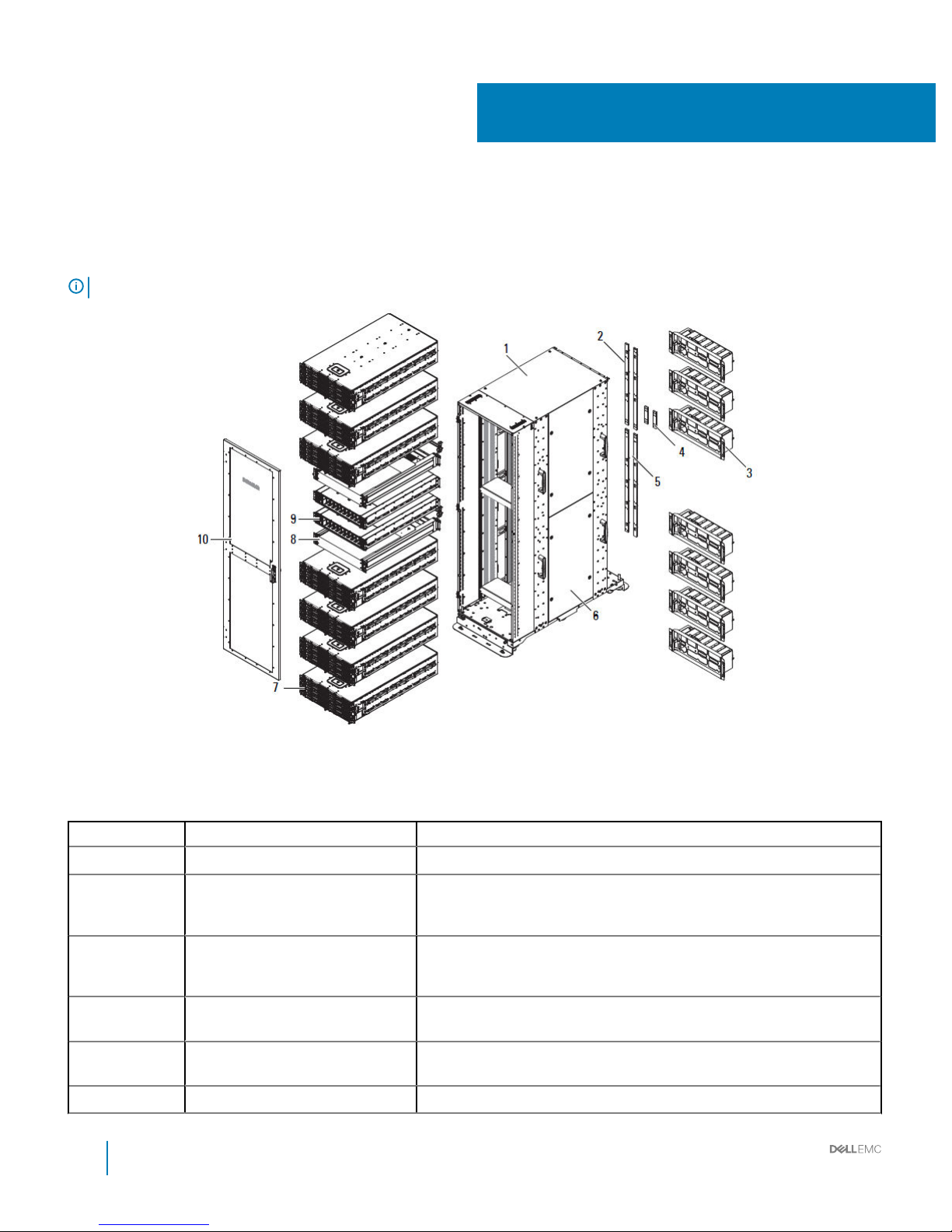
The DSS 9000 rack enclosure is designed to hold and protect server, network, and data storage equipment.
NOTE: The product at time of delivery may dier from the following illustrations.
Figure 1. DSS 9000 system
Table 1. DSS 9000 features
No. Feature Description
1 Bare rack Rack mounting enclosure for DSS 9000 system equipment.
2 Bus bar top Bar strip located on top of the rack conducts electricity. Based on rack layout,
two dierent types of top bus bars can be assembled. For more information
about bus bars, see Bus bar top.
3 Rear cabinet The rear cabinet houses twelve system fans, one block controller distribution
board (BCDB), one block controller (BC), one fan cage, one fan power
distribution board (FPDB), and one rear cabinet base.
4 Bus bar middle Bridge bus bar located between top and bottom bus bars. For more
information about bus bars, see Bus bar middle.
5 Bus bar bottom Bar strip located on bottom of the rack conducts electricity. For more
information about bus bars, see Bus bar bottom.
6 Side panel (optional) Rack cabinet ller panel (optional).
1
6 Installation and Service Manual
Overview
No. Feature Description
7 Block chassis Three types of block chassis (one third-width, half-width, and full-width).
8 OpenIT bay Two switch devices are available to provide networking for the entire system.
9 Power Bay Located on the front side of rack, provides allocated space for power supply
units (PSUs).
10 Front door (optional) Reversible front door can be congured to open from left or right, with lock.
Rack specications
Table 2. Rack specications
Item Description
Height Available rack options:
• 29U: 1,466.4 mm (57.73 inch)
• 42U: 1,970.4 mm (77.57 inch)
• 44U: 2,071.2 mm (81.54 inch)
• 48U: 2,272.8 mm (89.48 inch)
• 50U: 2,373.6 mm (93.45 inch)
Width 600 mm (23.62 inch)
Depth 1,200 mm (47.24 inch)
Net weight
• 29U: 162.4 kg (358 lb)
• 42U: 201.4 kg (444 lb)
• 44U: 207.3 kg (457 lb)
• 48U: 219.1 kg (483 lb)
• 50U: 225.0 kg (496 lb)
Installation and Service Manual
Overview
7

Rack accessories overview
The DSS 9000 rack enclosure oers server and power supply blanks as well as shipping brackets, bus bar protectors and optional side
panel accessories.
Topics:
• Server blanks
• Power supply unit (PSU) blanks (optional)
• Side panels (optional)
• Shipping brackets
• PDU brackets
• Power bay protectors
• Bus bar protectors
• Rack blank llers
• IM blank llers
• Locating Service Tag of your system
Server blanks
The following lists the available server blanks for the DSS 9000: full width, half width, and one third width blank chassis.
2
8 Installation and Service Manual
Rack accessories overview

Figure 2. Full-width server blank
Installation and Service Manual
Rack accessories overview
9
Table 3. Full-width server blank features
Item Description
Dimensions (W x L x H) 527 mm x 930 mm x 47 mm (20.75 inch x 36.61 inch x 1.85 inch)
10 Installation and Service Manual
Rack accessories overview
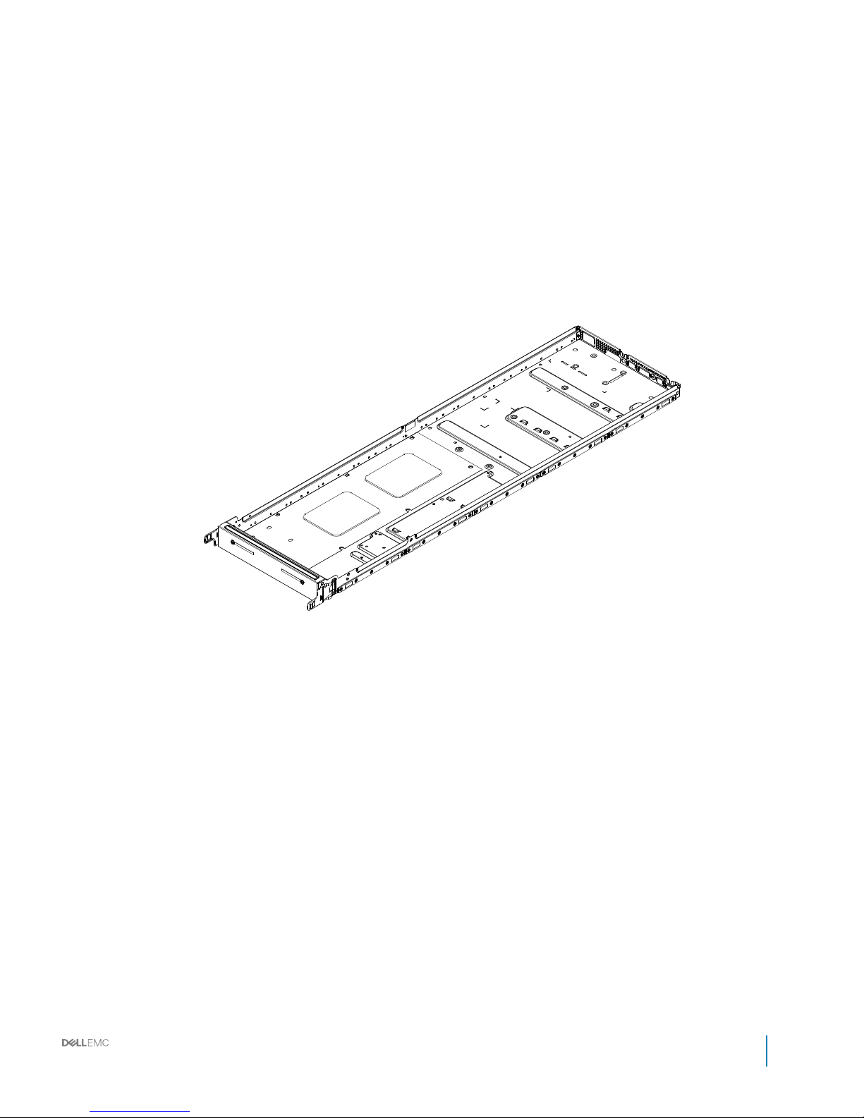
Figure 3. Half-width server blank
Installation and Service Manual
Rack accessories overview
11

Table 4. Full-width server blank features
Item Description
Dimensions (W x L x H) 262.2 mm x 930 mm x 47 mm (10.32 inch x 36.61 inch x 1.85 inch)
12 Installation and Service Manual
Rack accessories overview
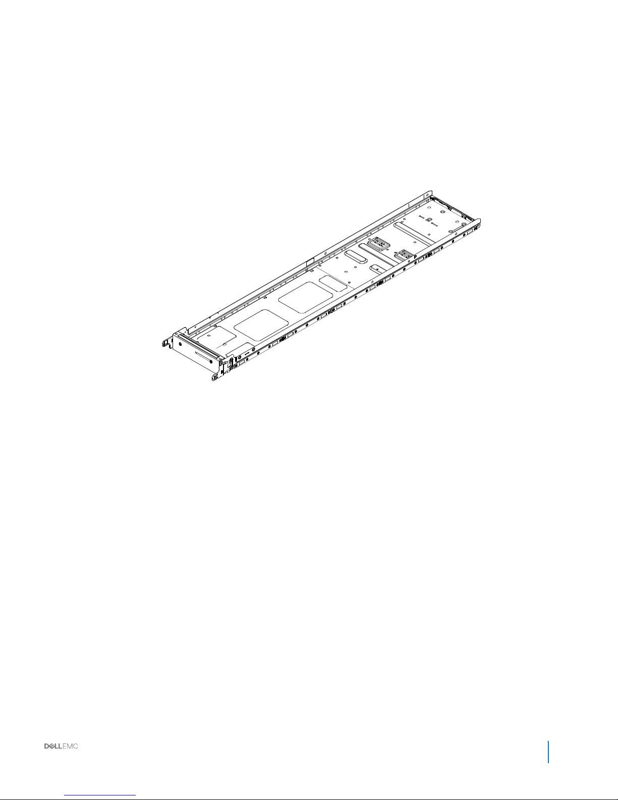
Figure 4. One third-width server blank
Installation and Service Manual
Rack accessories overview
13
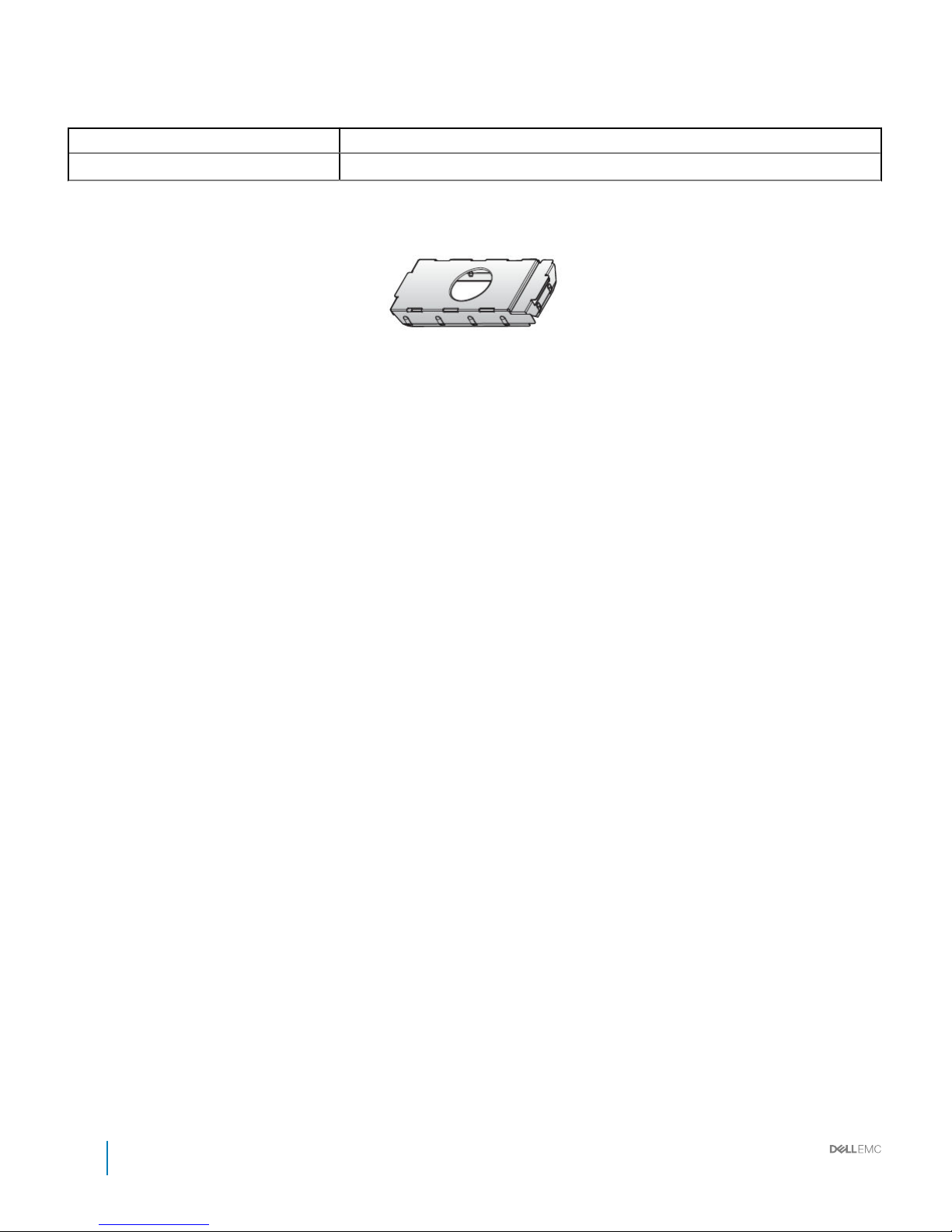
Table 5. Full-width server blank features
Item Description
Dimensions (W x L x H) 174.3 mm x 930 mm x 47 mm (6.86 inch x 36.61 inch x 1.85 inch)
Power supply unit (PSU) blanks (optional)
Figure 5. PSU blank
14 Installation and Service Manual
Rack accessories overview
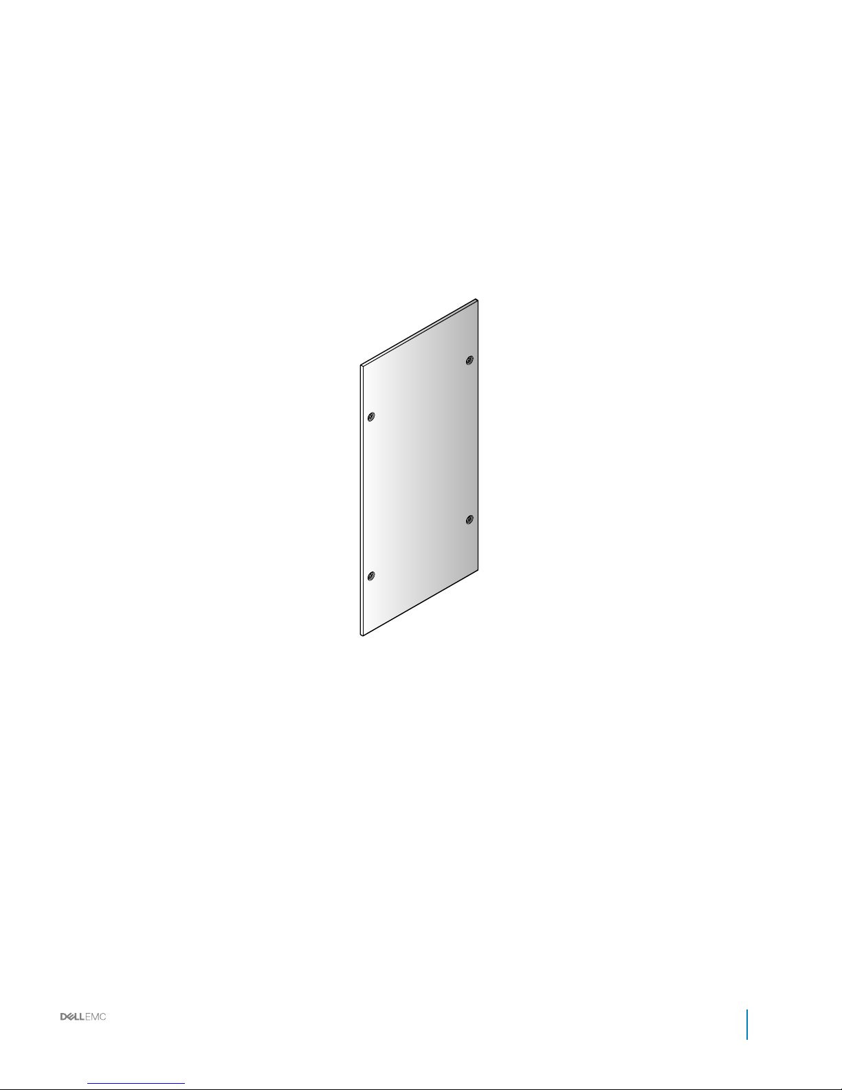
Side panels (optional)
Figure 6. Filler panel
Installation and Service Manual
Rack accessories overview
15
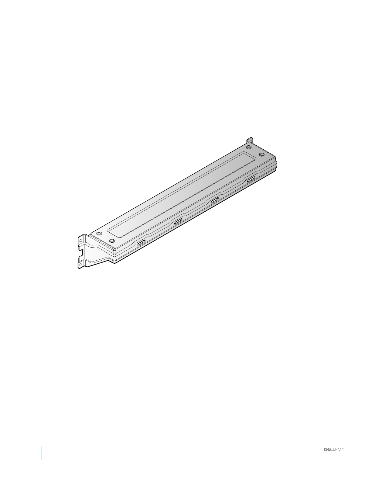
Shipping brackets
Figure 7. Shipping bracket
16
Installation and Service Manual
Rack accessories overview
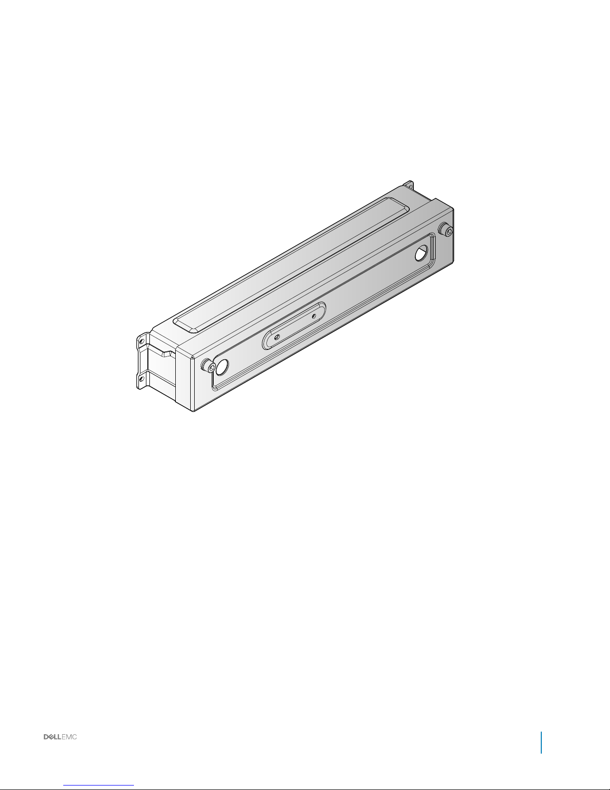
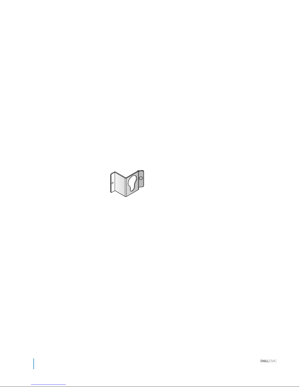
Figure 8. Shipping bracket
Installation and Service Manual
Rack accessories overview
17
PDU brackets
18 Installation and Service Manual
Rack accessories overview
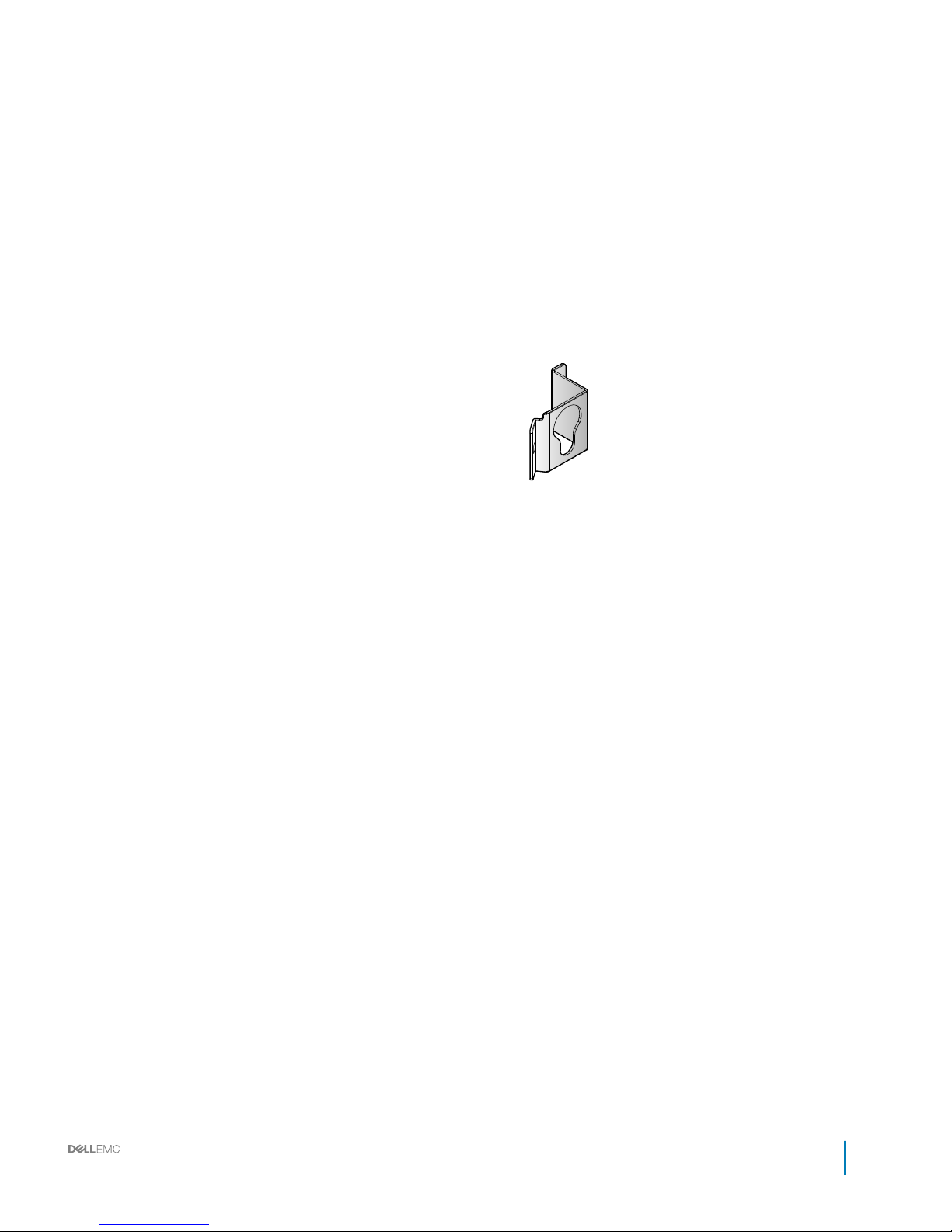
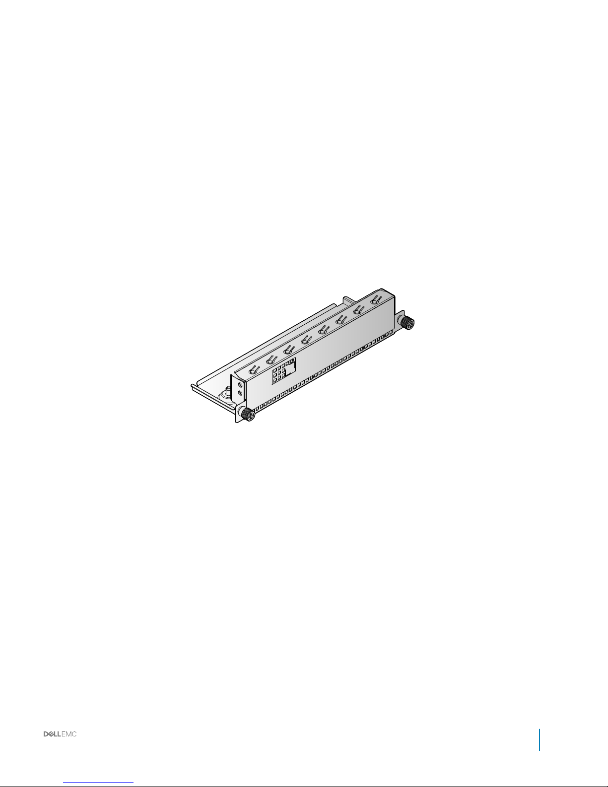
Figure 9. PDU bracket
Installation and Service Manual
Rack accessories overview
19
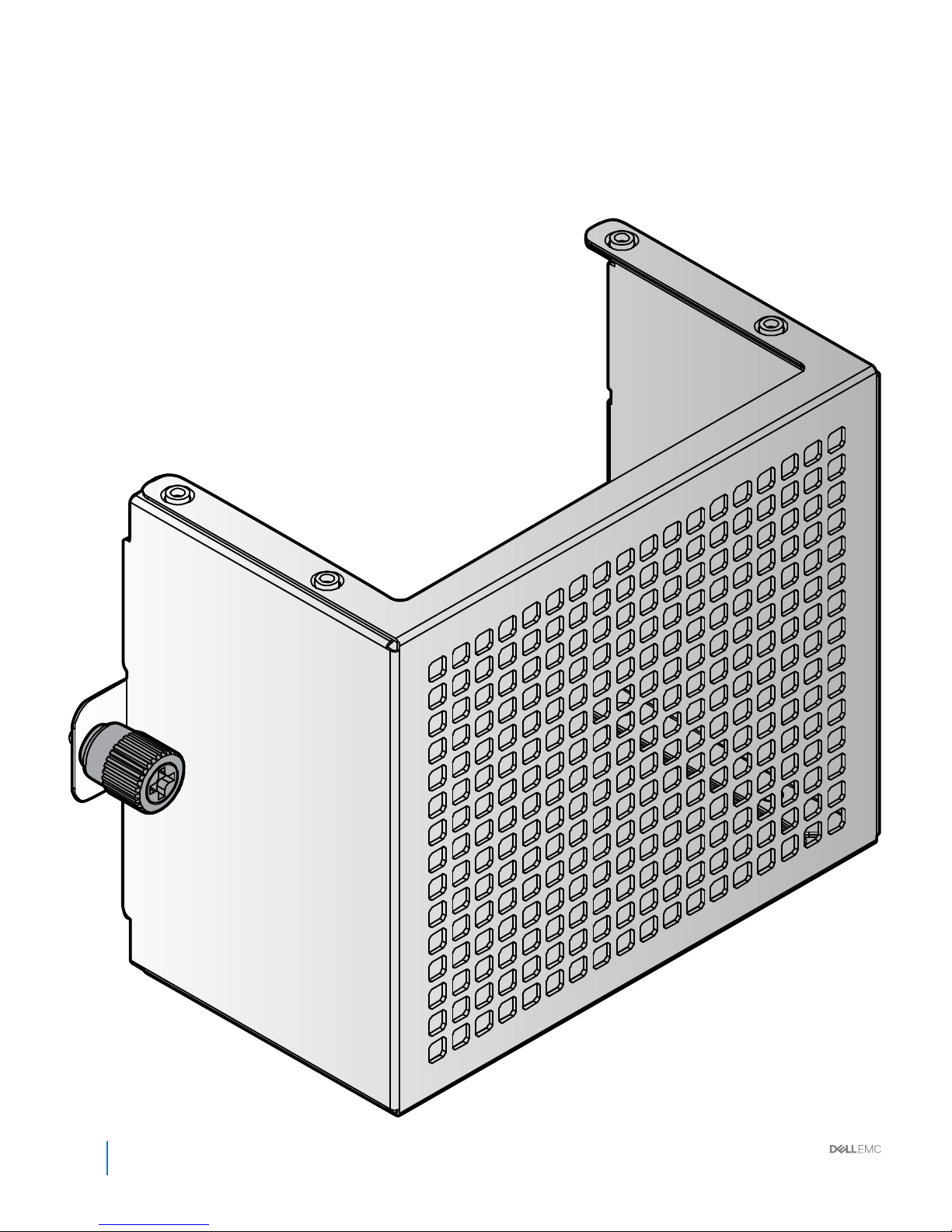
Power bay protectors
Figure 10. Power bay protector
20
Installation and Service Manual
Rack accessories overview
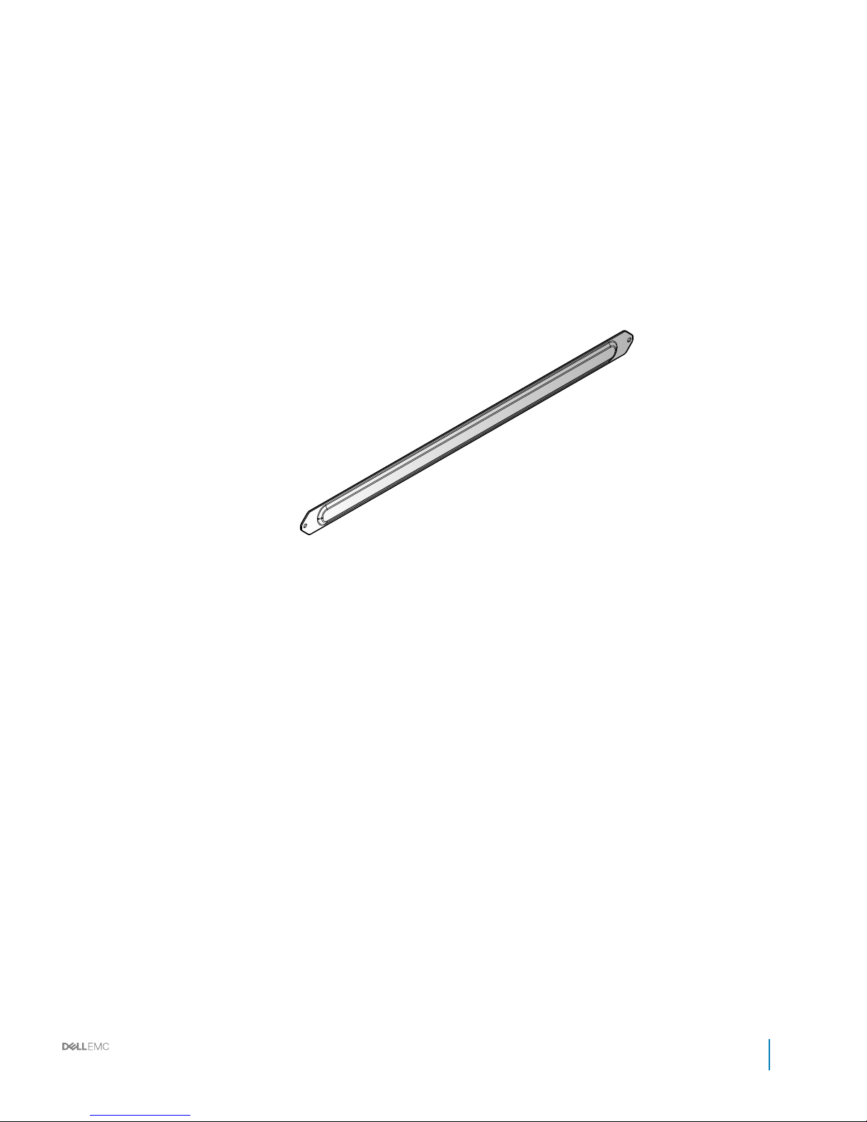
Bus bar protectors
Figure 11. 0.5GU bus bar protector
Installation and Service Manual
Rack accessories overview
21
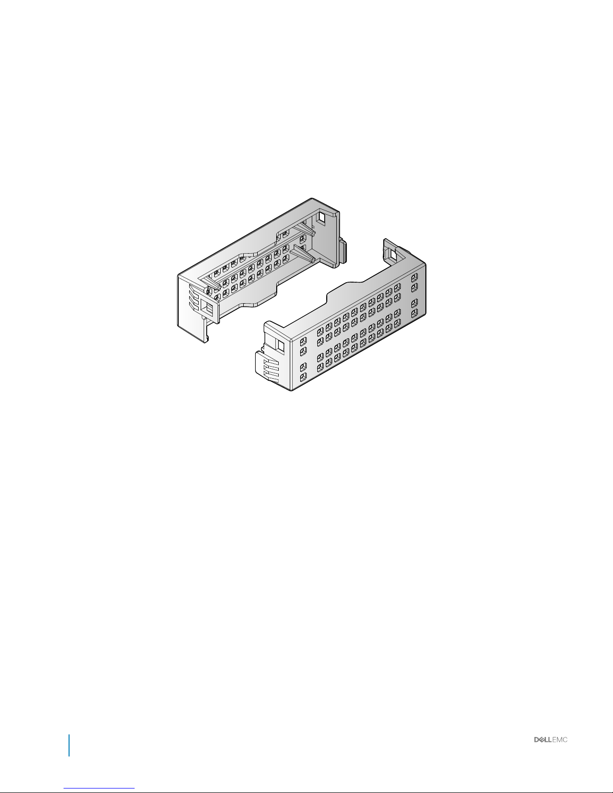
Figure 12. 1GU bus bar protector
22
Installation and Service Manual
Rack accessories overview
Rack blank llers
Figure 13. 1GU rack blank llers
Installation and Service Manual
Rack accessories overview
23
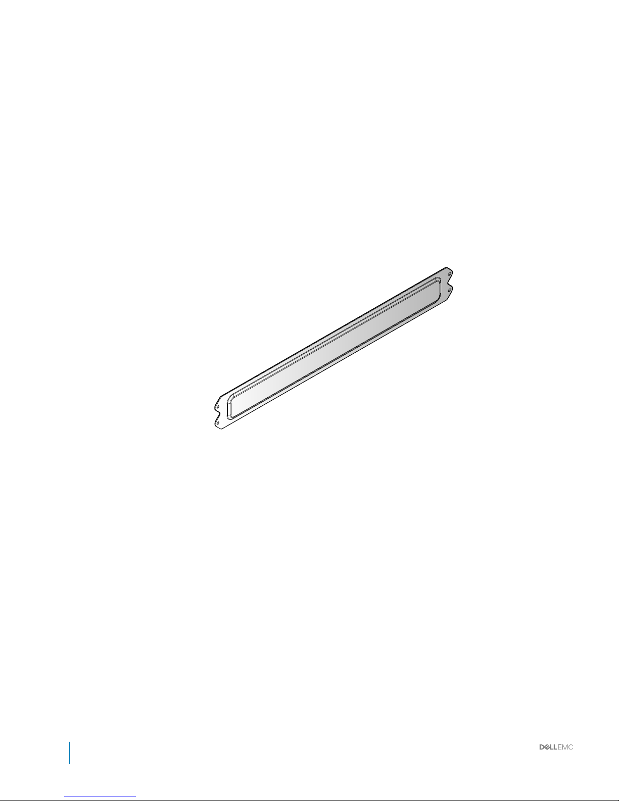
Figure 14. 2GU rack blank llers
24
Installation and Service Manual
Rack accessories overview

Figure 15. 3GU rack blank llers
Installation and Service Manual
Rack accessories overview
25
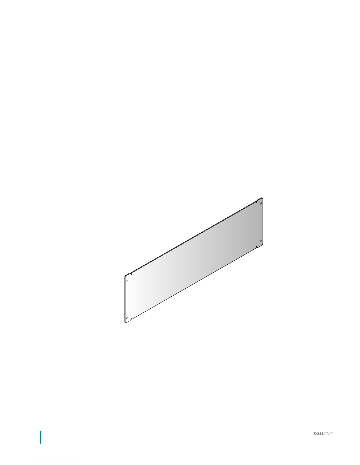
Figure 16. 5GU rack blank llers
26
Installation and Service Manual
Rack accessories overview
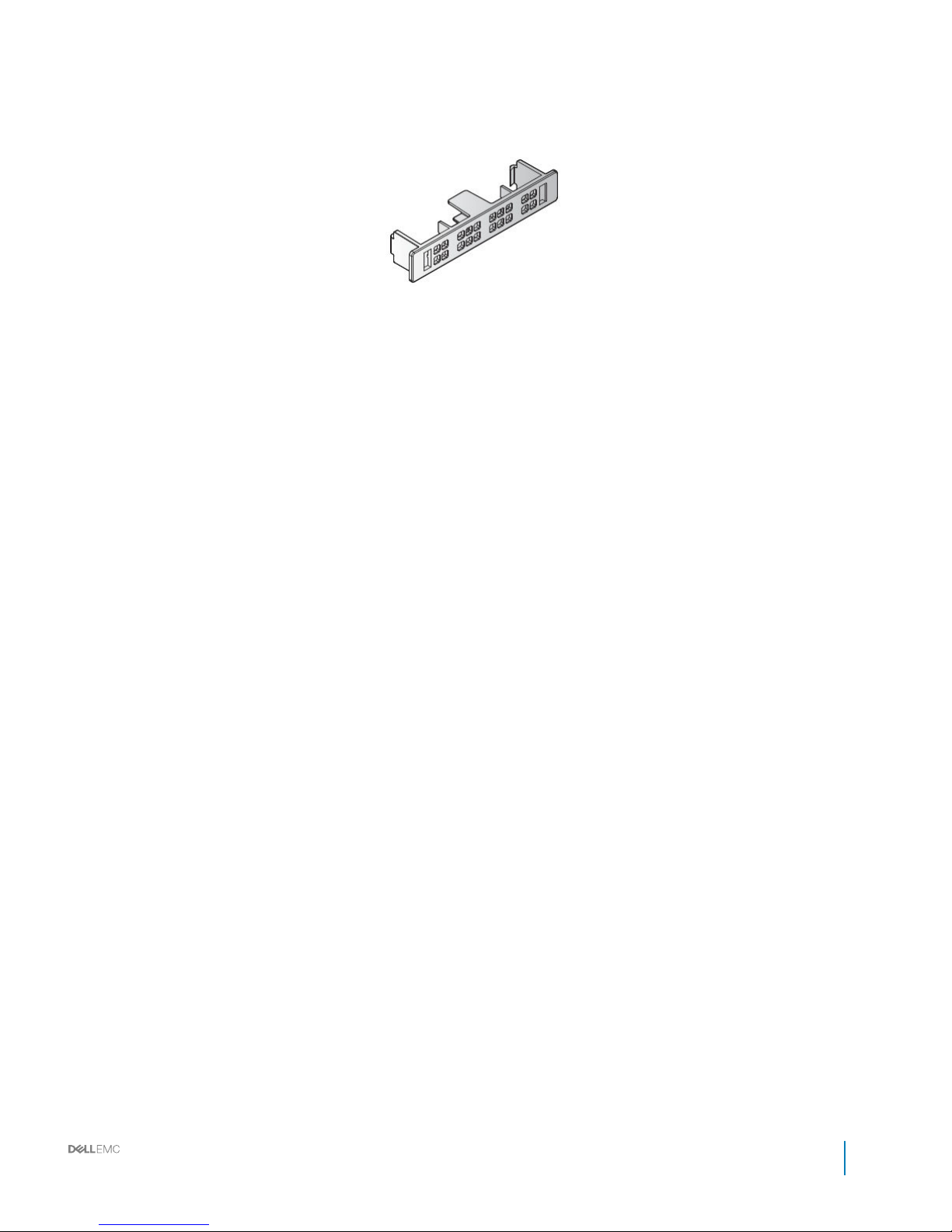
IM blank llers
Figure 17. IM blank llers
Installation and Service Manual
Rack accessories overview
27

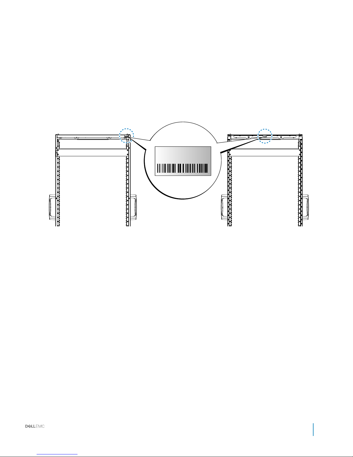
Locating Service Tag of your system
Your system is identied by a unique Express Service Code and Service Tag number. The information is on a sticker on the right-front of the
system. This information is used by Dell to route support calls to the appropriate personnel.
28 Installation and Service Manual
Rack accessories overview
Service Tag
BMMYG92
Service Tag
BMMYG92
Service Tag
BMMYG92
Figure 18. Service Tag location
Installation and Service Manual
Rack accessories overview
29
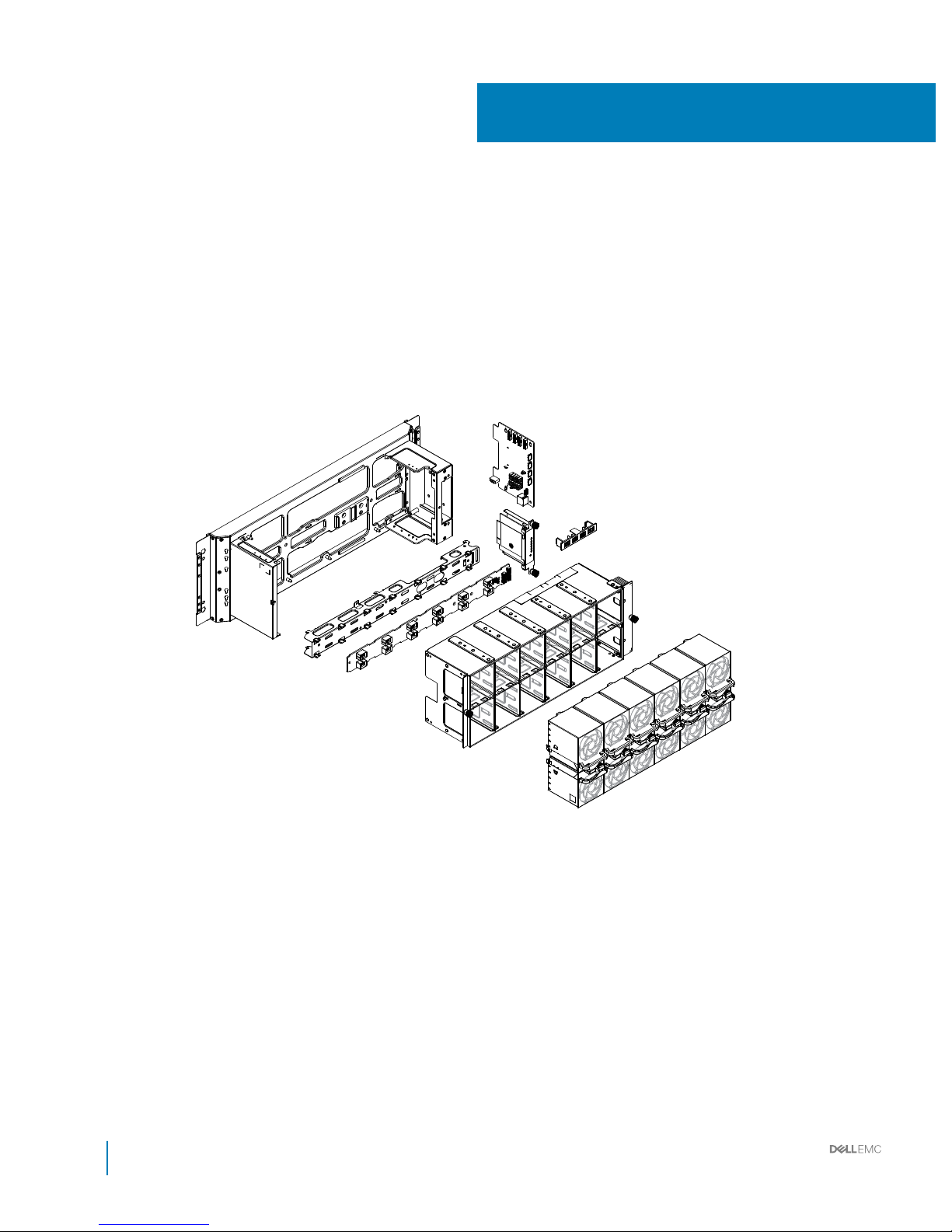
Rear cabinet overview
3
30 Installation and Service Manual
Rear cabinet overview
 Loading...