

Page 1

Dell EMC DD OS
Version 7.0
Administration Guide
Revision 02
March 2020
Page 2

Copyright © 2010-2020 Dell Inc. or its subsidiaries All rights reserved.
Dell believes the information in this publication is accurate as of its publication date. The information is subject to change without notice.
THE INFORMATION IN THIS PUBLICATION IS PROVIDED “AS-IS.” DELL MAKES NO REPRESENTATIONS OR WARRANTIES OF ANY KIND
WITH RESPECT TO THE INFORMATION IN THIS PUBLICATION, AND SPECIFICALLY DISCLAIMS IMPLIED WARRANTIES OF
MERCHANTABILITY OR FITNESS FOR A PARTICULAR PURPOSE. USE, COPYING, AND DISTRIBUTION OF ANY DELL SOFTWARE DESCRIBED
IN THIS PUBLICATION REQUIRES AN APPLICABLE SOFTWARE LICENSE.
Dell Technologies, Dell, EMC, Dell EMC and other trademarks are trademarks of Dell Inc. or its subsidiaries. Other trademarks may be the property
of their respective owners. Published in the USA.
Dell EMC
Hopkinton, Massachusetts 01748-9103
1-508-435-1000 In North America 1-866-464-7381
www.DellEMC.com
2 Dell EMC DD OS Administration Guide
Page 3

CONTENTS
Preface 15
Chapter 1
Chapter 2
System Features and Integration 17
Revision history................................................................................................. 18
System overview............................................................................................... 18
System features................................................................................................ 19
Data integrity........................................................................................19
Data deduplication............................................................................... 20
Restore operations...............................................................................20
DD Replicator.......................................................................................20
Multipath and load balancing................................................................20
High Availability.................................................................................... 21
Random I/O handling........................................................................... 22
System administrator access............................................................... 23
Licensed features.................................................................................23
Storage environment integration...................................................................... 24
Getting Started 27
Dell EMC DD System Manager overview...........................................................28
Logging in and out of DD System Manager....................................................... 28
Log in with certificate using CAC/PIV card..........................................30
Logging in using single sign-on (SSO).................................................. 31
The DD System Manager interface....................................................................31
Page elements..................................................................................... 32
Banner................................................................................................. 32
Navigation panel...................................................................................32
Information panel................................................................................. 32
Footer.................................................................................................. 33
Help buttons........................................................................................ 33
End User License Agreement............................................................... 33
Configuring the system with the configuration wizard...................................... 34
License page........................................................................................ 34
Network...............................................................................................35
File System.......................................................................................... 37
System Settings................................................................................... 41
DD Boost protocol................................................................................42
CIFS protocol.......................................................................................43
NFS protocol........................................................................................44
DD VTL protocol.................................................................................. 45
Configure NTP..................................................................................................46
Managing time and date settings......................................................... 46
Command line interface.................................................................................... 47
Logging into the CLI..........................................................................................47
CLI online help guidelines.................................................................................. 48
Chapter 3
Managing the Protection System 51
System management overview......................................................................... 52
HA system management overview....................................................... 52
Dell EMC DD OS Administration Guide 3
Page 4

Contents
HA system planned maintenance......................................................... 52
Restarting a protection system.........................................................................53
Powering a protection system on or off ........................................................... 53
Power a protection system on............................................................. 54
System upgrade management.......................................................................... 55
Pre-upgrade checklists and overview...................................................55
Viewing upgrade packages on the protection system...........................60
Obtaining and verifying upgrade packages...........................................60
Upgrading a protection system.............................................................61
Removing an upgrade package.............................................................62
Managing electronic licenses............................................................................ 62
HA system license management...........................................................63
Protection system storage management...........................................................63
Viewing system storage information.................................................... 64
Physically locating an enclosure...........................................................68
Physically locating a disk......................................................................69
Configuring storage............................................................................. 69
DD3300 capacity expansion................................................................. 70
Fail and unfail disks............................................................................... 71
Network connection management..................................................................... 71
HA system network connection management....................................... 71
Network interface management........................................................... 72
General network settings management................................................85
Network route management................................................................ 89
System passphrase management......................................................................92
Setting the system passphrase............................................................ 92
Changing the system passphrase.........................................................93
Configuring mail server settings........................................................................93
Managing system properties.............................................................................94
SNMP management..........................................................................................94
Viewing SNMP status and configuration..............................................95
Enabling and disabling SNMP...............................................................96
Downloading the SNMP MIB................................................................96
Configuring SNMP properties.............................................................. 97
SNMP V3 user management................................................................ 97
SNMP V2C community management................................................... 99
SNMP trap host management............................................................. 101
Autosupport report management.....................................................................102
Setup sending ASUP using the GUI.................................................... 103
HA system autosupport and support bundle manageability.................104
Enabling and disabling autosupport reporting to Dell EMC..................104
Reviewing generated autosupport reports..........................................104
Configuring the autosupport mailing list............................................. 104
Verifying the system is able to send ASUP and alert emails to external
recipients............................................................................................105
Support bundle management...........................................................................106
Generating a support bundle...............................................................106
Generating a mini support bundle....................................................... 106
Viewing the support bundles list......................................................... 107
Coredump management...................................................................................107
Splitting a coredump file..................................................................... 107
Alert notification management........................................................................ 108
HA system alert notification management.......................................... 109
Viewing the notification group list...................................................... 109
Creating a notification group................................................................111
Managing the subscriber list for a group.............................................. 111
4 Dell EMC DD OS Administration Guide
Page 5

Contents
Modifying a notification group.............................................................112
Deleting a notification group............................................................... 113
Resetting the notification group configuration.................................... 113
Configuring the daily summary schedule and distribution list...............113
Enabling and disabling alert notification to Dell EMC...........................115
Testing the alerts email feature...........................................................115
Support delivery management..........................................................................116
Selecting standard email delivery to Dell EMC.................................... 116
Selecting and configuring Secure Remote Services delivery............... 116
Testing ConnectEMC operation.......................................................... 117
Log file management........................................................................................118
Viewing log files in DD System Manager..............................................119
Displaying a log file in the CLI..............................................................119
Learning more about log messages..................................................... 120
Saving a copy of log files.................................................................... 120
Log message transmission to remote systems.....................................121
Remote system power management with IPMI................................................122
IPMI and SOL limitations.................................................................... 123
Adding and deleting IPMI users with DD System Manager..................123
Changing an IPMI user password........................................................ 124
Configuring an IPMI port.................................................................... 124
Preparing for remote power management and console monitoring with
the CLI................................................................................................125
Managing power with DD System Manager........................................ 126
Managing power with the CLI............................................................. 127
System access management............................................................................127
Role-based access control..................................................................128
Access management for IP protocols................................................. 129
Local user account management........................................................ 135
Directory user and group management............................................... 142
Diagnosing authentication issues........................................................ 157
Change system authentication method...............................................158
Reset the iDRAC password.................................................................159
Chapter 4
Monitoring Protection Systems 161
Viewing individual system status and identity information............................... 162
Dashboard Alerts area.........................................................................162
Dashboard File System area................................................................163
Dashboard Services area.................................................................... 163
Dashboard HA Readiness area............................................................ 164
Dashboard Hardware area.................................................................. 164
Maintenance System area.................................................................. 164
Health Alerts panel.......................................................................................... 165
Viewing and clearing current alerts..................................................................165
Current Alerts tab...............................................................................166
Viewing the alerts history................................................................................ 166
Alerts History tab................................................................................167
Viewing hardware component status............................................................... 167
Fan status...........................................................................................168
Temperature status............................................................................ 168
Management panel status...................................................................169
SSD status (DD6300 only)................................................................. 169
Power supply status........................................................................... 170
PCI slot status.................................................................................... 170
NVRAM status....................................................................................170
Dell EMC DD OS Administration Guide 5
Page 6

Contents
Viewing system statistics................................................................................. 171
Performance statistics graphs.............................................................171
Viewing active users........................................................................................ 172
History report management.............................................................................173
Types of reports................................................................................. 173
Viewing the Task Log.......................................................................................177
Viewing the system High Availability status..................................................... 178
High Availability status........................................................................178
Chapter 5
Chapter 6
File System 181
File system overview....................................................................................... 182
How the file system stores data..........................................................182
How the file system reports space usage............................................182
How the file system uses compression .............................................. 182
How the file system implements data integrity................................... 184
How the file system reclaims storage space with file system cleaning....
184
Supported interfaces ......................................................................... 185
Supported backup software................................................................185
Data streams sent to a protection system ......................................... 185
File system limitations.........................................................................187
Monitoring file system usage........................................................................... 188
Accessing the file system view........................................................... 189
Managing file system operations..................................................................... 195
Performing basic operations............................................................... 195
Performing cleaning............................................................................197
Performing sanitization.......................................................................199
Modifying basic settings..................................................................... 201
Fast copy operations.......................................................................................203
Performing a fast copy operation.......................................................203
MTrees 205
MTrees overview............................................................................................ 206
MTree limits.......................................................................................206
Quotas............................................................................................... 206
About the MTree panel.......................................................................207
About the summary view....................................................................207
About the space usage view (MTrees)................................................212
About the daily written view (MTrees)............................................... 212
Monitoring MTree usage..................................................................................213
Understanding physical capacity measurement.................................. 214
Managing MTree operations............................................................................216
Creating an MTree..............................................................................216
Configure and enable/disable MTree quotas.......................................218
Deleting an MTree.............................................................................. 218
Undeleting an MTree.......................................................................... 219
Renaming an MTree............................................................................219
Chapter 7
6 Dell EMC DD OS Administration Guide
Snapshots 221
Snapshots overview........................................................................................ 222
Monitoring snapshots and their schedules...................................................... 222
About the snapshots view.................................................................. 222
Managing snapshots....................................................................................... 224
Creating a snapshot........................................................................... 224
Page 7

Contents
Modifying a snapshot expiration date.................................................224
Renaming a snapshot......................................................................... 225
Expiring a snapshot............................................................................225
Managing snapshot schedules........................................................................ 225
Creating a snapshot schedule............................................................ 226
Modifying a snapshot schedule.......................................................... 227
Deleting a snapshot schedule............................................................. 227
Recover data from a snapshot........................................................................ 227
Chapter 8
CIFS 229
CIFS overview.................................................................................................230
Performing CIFS setup................................................................................... 230
HA systems and CIFS.........................................................................230
Preparing clients for access to protection systems............................ 231
Enabling CIFS services........................................................................231
Naming the CIFS server......................................................................231
Setting authentication parameters.....................................................232
Disabling CIFS services...................................................................... 232
Working with shares........................................................................................232
Creating shares.................................................................................. 233
Modifying a share...............................................................................235
Creating a share from an existing share............................................. 235
Disabling a share................................................................................ 236
Enabling a share................................................................................. 236
Deleting a share................................................................................. 236
Performing MMC administration........................................................236
Connecting to a protection system from a CIFS client....................... 236
Displaying CIFS information .............................................................. 237
Configuring SMB signing.................................................................................237
Managing access control................................................................................ 238
Accessing shares from a Windows client............................................238
Providing domain users administrative access....................................238
Allowing administrative access to a protection system for domain users
.......................................................................................................... 239
Restricting administrative access from Windows............................... 239
File access......................................................................................... 239
Monitoring CIFS operation..............................................................................242
Displaying CIFS status....................................................................... 242
Display CIFS configuration................................................................. 243
Displaying CIFS statistics...................................................................245
Performing CIFS troubleshooting....................................................................245
Displaying clients current activity...................................................... 245
Setting the maximum open files on a connection............................... 246
System clock......................................................................................246
Synchronize from an NTP server....................................................... 246
Chapter 9
NFS 247
NFS overview................................................................................................. 248
HA systems and NFS..........................................................................248
Managing NFS client access to the protection system................................... 248
Enabling NFS services........................................................................249
Disabling NFS services.......................................................................249
Creating an export............................................................................. 249
Modifying an export...........................................................................250
Dell EMC DD OS Administration Guide 7
Page 8

Contents
Creating an export from an existing export.........................................251
Deleting an export..............................................................................252
Displaying NFS information.............................................................................252
Viewing NFS status............................................................................252
Viewing NFS exports..........................................................................252
Viewing active NFS clients.................................................................252
Integrating a DDR into a Kerberos domain...................................................... 253
Add and delete KDC servers after initial configuration.................................... 254
Chapter 10
NFSv4 257
Introduction to NFSv4.................................................................................... 258
NFSv4 compared to NFSv3............................................................... 258
NFSv4 ports.......................................................................................259
ID Mapping Overview......................................................................................259
External formats............................................................................................. 259
Standard identifier formats................................................................ 259
ACE extended identifiers................................................................... 260
Alternative formats............................................................................ 260
Internal Identifier Formats.............................................................................. 260
When ID mapping occurs................................................................................ 260
Input mapping.....................................................................................261
Output mapping..................................................................................261
Credential mapping.............................................................................261
NFSv4 and CIFS/SMB Interoperability........................................................... 262
CIFS/SMB Active Directory Integration.............................................262
Default DACL for NFSv4.................................................................... 262
System Default SIDs.......................................................................... 262
Common identifiers in NFSv4 ACLs and SIDs.....................................263
NFS Referrals................................................................................................. 263
Referral Locations..............................................................................263
Referral location names......................................................................263
Referrals and Scaleout Systems.........................................................264
NFSv4 and High Availability............................................................................ 264
NFSv4 Global Namespaces............................................................................. 264
NFSv4 global namespaces and NFSv3 submounts............................. 265
NFSv4 Configuration...................................................................................... 265
Enabling the NFSv4 Server................................................................ 266
Setting the default server to include NFSv4...................................... 266
Updating existing exports.................................................................. 266
Kerberos and NFSv4....................................................................................... 266
Configuring Kerberos with a Linux-Based KDC...................................267
Configuring the protection System to Use Kerberos Authentication.. 268
Configuring Clients............................................................................ 269
Enabling Active Directory................................................................................269
Configuring Active Directory..............................................................270
Configuring clients on Active Directory.............................................. 270
Chapter 11
8 Dell EMC DD OS Administration Guide
Storage Migration 271
Storage migration overview............................................................................ 272
Migration planning considerations...................................................................272
DS60 shelf considerations..................................................................273
Viewing migration status................................................................................. 274
Evaluating migration readiness........................................................................274
Migrating storage using DD System Manager................................................. 275
Page 9

Contents
Storage migration dialog descriptions............................................................. 276
Select a Task dialog............................................................................276
Select Existing Enclosures dialog....................................................... 276
Select New Enclosures dialog............................................................ 276
Review Migration Plan dialog............................................................. 276
Verify Migration Preconditions dialog.................................................277
Migration progress dialogs................................................................. 277
Migrating storage using the CLI...................................................................... 278
CLI storage migration example........................................................................279
Chapter 12
Chapter 13
Chapter 14
Metadata on Flash 285
Overview of Metadata on Flash (MDoF) ........................................................ 286
SSD cache licensing and capacity................................................................... 286
SSD cache tier................................................................................................ 288
SSD cache tier - system management ........................................................... 288
Managing the SSD cache tier.............................................................288
SSD alerts....................................................................................................... 291
SCSI Target 293
SCSI Target overview..................................................................................... 294
Fibre Channel view..........................................................................................295
Enabling NPIV.................................................................................... 295
Disabling NPIV....................................................................................297
Resources tab.................................................................................... 298
Access Groups tab............................................................................. 304
Port monitoring...............................................................................................304
Working with DD Boost 305
About DD Boost.............................................................................................. 306
Managing DD Boost with DD System Manager............................................... 306
Specifying DD Boost user names........................................................307
Changing DD Boost user passwords...................................................307
Removing a DD Boost user name....................................................... 308
Enabling DD Boost............................................................................. 308
Configuring Kerberos......................................................................... 308
Disabling DD Boost.............................................................................309
Viewing DD Boost storage units......................................................... 309
Creating a storage unit....................................................................... 310
Viewing storage unit information......................................................... 311
Modifying a storage unit..................................................................... 313
Renaming a storage unit..................................................................... 314
Deleting a storage unit........................................................................315
Undeleting a storage unit....................................................................315
Selecting DD Boost options................................................................ 315
Managing certificates for DD Boost.................................................... 317
Managing DD Boost client access and encryption...............................318
About interface groups................................................................................... 320
Interfaces...........................................................................................320
Clients................................................................................................ 321
Creating interface groups.................................................................. 322
Enabling and disabling interface groups............................................. 323
Modifying an interface group's name and interfaces.......................... 323
Deleting an interface group................................................................ 323
Adding a client to an interface group..................................................324
Dell EMC DD OS Administration Guide 9
Page 10

Contents
Modifying a client's name or interface group......................................324
Deleting a client from the interface group..........................................325
Using interface groups for Managed File Replication (MFR)..............325
Destroying DD Boost.......................................................................................326
Configuring DD Boost-over-Fibre Channel...................................................... 327
Enabling DD Boost users.................................................................... 327
Configuring DD Boost........................................................................ 328
Verifying connectivity and creating access groups.............................329
Using DD Boost on HA systems....................................................................... 331
About the DD Boost tabs................................................................................. 331
Settings.............................................................................................. 331
Active Connections............................................................................ 332
IP Network.........................................................................................333
Fibre Channel..................................................................................... 333
Storage Units..................................................................................... 333
Chapter 15
DD Virtual Tape Library 335
DD Virtual Tape Library overview....................................................................336
Planning a DD VTL.......................................................................................... 336
DD VTL limits..................................................................................... 337
Number of drives supported by a DD VTL.......................................... 340
Tape barcodes................................................................................... 340
LTO tape drive compatibility...............................................................341
Setting up a DD VTL...........................................................................342
HA systems and DD VTL.................................................................... 342
DD VTL tape out to cloud................................................................... 342
Managing a DD VTL........................................................................................ 342
Enabling DD VTL................................................................................ 344
Disabling DD VTL................................................................................344
DD VTL option defaults...................................................................... 344
Configuring DD VTL default options...................................................345
Working with libraries..................................................................................... 346
Creating libraries................................................................................ 347
Deleting libraries................................................................................ 349
Searching for tapes............................................................................349
Working with a selected library.......................................................................350
Creating tapes................................................................................... 350
Deleting tapes.....................................................................................351
Importing tapes..................................................................................352
Exporting tapes..................................................................................354
Moving tapes between devices within a library.................................. 355
Adding slots....................................................................................... 356
Deleting slots..................................................................................... 356
Adding CAPs...................................................................................... 357
Deleting CAPs.................................................................................... 357
Viewing changer information...........................................................................357
Working with drives........................................................................................ 358
Creating drives...................................................................................359
Deleting drives................................................................................... 359
Working with a selected drive......................................................................... 360
Working with tapes..........................................................................................361
Changing a tape's write or retention lock state.................................. 362
Working with the vault....................................................................................362
Working with the cloud-based vault................................................................363
Prepare the VTL pool for data movement.......................................... 363
10 Dell EMC DD OS Administration Guide
Page 11

Contents
Remove tapes from the backup application inventory........................365
Select tape volumes for data movement............................................ 365
Restore data held in the cloud............................................................367
Manually recall a tape volume from cloud storage.............................. 367
Working with access groups........................................................................... 369
Creating an access group...................................................................369
Deleting an access group....................................................................373
Working with a selected access group............................................................ 373
Selecting endpoints for a device........................................................ 374
Configuring the NDMP device TapeServer group...............................374
Working with resources.................................................................................. 375
Working with initiators....................................................................... 376
Working with endpoints......................................................................377
Working with a selected endpoint...................................................... 378
Working with pools..........................................................................................379
Creating pools....................................................................................380
Deleting pools..................................................................................... 381
Working with a selected pool.......................................................................... 382
Converting a directory pool to an MTree pool ................................... 384
Moving tapes between pools..............................................................384
Copying tapes between pools............................................................ 385
Renaming pools..................................................................................386
Chapter 16
DD Replicator 387
DD Replicator overview...................................................................................388
Prerequisites for replication configuration...................................................... 389
Replication version compatibility..................................................................... 391
Replication types............................................................................................ 393
Managed file replication .................................................................... 394
Directory replication...........................................................................394
MTree replication...............................................................................395
Collection replication .........................................................................397
Using DD Encryption with DD Replicator........................................................ 398
Replication topologies.....................................................................................399
One-to-one replication.......................................................................400
Bi-directional replication.....................................................................401
One-to-many replication.....................................................................401
Many-to-one replication.....................................................................402
Cascaded replication..........................................................................402
Managing replication.......................................................................................403
Replication status.............................................................................. 404
Summary view....................................................................................404
DD Boost view.................................................................................... 414
Performance view...............................................................................415
Advanced Settings view..................................................................... 415
Monitoring replication .....................................................................................418
Viewing estimated completion time for backup jobs........................... 418
Checking replication context performance......................................... 419
Tracking status of a replication process..............................................419
Replication lag.................................................................................... 419
Replication with HA......................................................................................... 419
Replicating a system with quotas to one without............................................ 420
Replication Scaling Context ........................................................................... 420
Directory-to-MTree replication migration....................................................... 420
Performing migration from directory replication to MTree replication420
Dell EMC DD OS Administration Guide 11
Page 12

Contents
Viewing directory-to-MTree migration progress................................. 421
Checking the status of directory-to-MTree replication migration...... 422
Aborting D2M replication .................................................................. 422
Troubleshooting D2M.........................................................................423
Additional D2M troubleshooting......................................................... 424
Using collection replication for disaster recovery with SMT............................424
Chapter 17
Chapter 18
DD Secure Multitenancy 427
Secure Multi-Tenancy overview......................................................................428
SMT architecture basics.................................................................... 428
Terminology used in Secure Multi-Tenancy (SMT)............................ 428
Control path and network isolation.....................................................429
Understanding RBAC in SMT............................................................. 430
Provisioning a Tenant Unit...............................................................................431
Enabling Tenant Self-Service mode................................................................ 435
Data access by protocol..................................................................................435
Multi-User DD Boost and Storage Units in SMT.................................435
Configuring access for CIFS...............................................................436
Configuring NFS access.....................................................................436
Configuring access for DD VTL.......................................................... 436
Using DD VTL NDMP TapeServer ..................................................... 437
Data management operations..........................................................................437
Collecting performance statistics.......................................................437
Modifying quotas................................................................................437
SMT and replication........................................................................... 438
SMT Tenant alerts............................................................................. 439
Managing snapshots.......................................................................... 439
Performing a file system Fast Copy................................................... 440
Cloud Tier 441
Cloud Tier overview........................................................................................ 442
Supported platforms.......................................................................... 442
Cloud Tier performance......................................................................444
Configuring Cloud Tier.................................................................................... 445
Configuring storage for Cloud Tier.....................................................445
Configuring cloud units................................................................................... 446
Firewall and proxy settings.................................................................447
Importing CA certificates................................................................... 447
Adding a cloud unit for Elastic Cloud Storage (ECS)..........................448
Adding a cloud unit for Alibaba...........................................................449
Adding a cloud unit for Amazon Web Services S3...............................451
Adding a cloud unit for Azure............................................................. 452
Adding a cloud unit for Google Cloud Provider................................... 453
Adding an S3 Flexible provider cloud unit...........................................455
Modifying a cloud unit or cloud profile............................................... 456
Deleting a cloud unit...........................................................................457
Data movement.............................................................................................. 458
Adding data movement policies to MTrees.........................................458
Moving data manually........................................................................ 458
Moving data automatically................................................................. 459
Recalling a file from the Cloud Tier.................................................... 459
Using the CLI to recall a file from the cloud tier................................. 460
Direct restore from the cloud tier....................................................... 461
Using the CLI to configure Cloud Tier..............................................................461
12 Dell EMC DD OS Administration Guide
Page 13

Contents
Configuring encryption for DD cloud units...................................................... 465
Information needed in the event of system loss.............................................. 465
Using DD Replicator with Cloud Tier............................................................... 466
Using DD Virtual Tape Library (VTL) with Cloud Tier...................................... 466
Displaying capacity consumption charts for Cloud Tier...................................466
Cloud Tier logs................................................................................................ 467
Using the CLI to remove Cloud Tier................................................................ 467
Chapter 19
DD Retention Lock 471
DD Retention Lock overview........................................................................... 472
DD Retention Lock protocol............................................................... 473
DD Retention Lock flow......................................................................473
Automatic retention lock.................................................................... 473
Supported data access protocols.................................................................... 474
Compliance mode on iDRAC............................................................................475
Create an iDRAC user account...........................................................475
Request PowerProtect access for iDRAC administrators...................475
Extend PowerProtect access for iDRAC administrators.....................476
Disable PowerProtect access for iDRAC administrators.....................476
Enabling DD Retention Lock on an MTree....................................................... 476
Enabling DD Retention Lock Governance on an MTree.......................477
Enabling DD Retention Lock Compliance on an MTree....................... 478
Client-Side Retention Lock file control........................................................... 480
Setting Retention Locking on a file..................................................... 481
Extending Retention Locking on a file................................................ 483
Identifying a Retention-Locked file.................................................... 484
Specifying a directory and touching only those files...........................484
Reading a list of files and touching only those files.............................484
Deleting or expiring a file....................................................................484
Using ctime or mtime on Retention-Locked files................................485
System behavior with DD Retention Lock.......................................................485
DD Retention Lock governance..........................................................485
DD Retention Lock compliance...........................................................487
Chapter 20
DD Encryption 497
DD Encryption overview..................................................................................498
Configuring encryption................................................................................... 498
About key management.................................................................................. 499
Rectifying lost or corrupted keys....................................................... 499
Key manager support.........................................................................500
Working with the Embedded Key Manager........................................ 500
Working with KeySecure Key Manager...............................................501
Using DD System Manager to set up and manage the KeySecure Key
Manager............................................................................................. 501
Using the DD CLI to manage the KeySecure Key Manager.................503
How the cleaning operation works..................................................... 507
Key manager setup......................................................................................... 507
Setting up KMIP key manager............................................................507
Changing key managers after setup................................................................509
Deleting certificates...........................................................................509
Checking DD Encryption settings................................................................... 509
Enabling and disabling DD Encryption..............................................................510
Enabling DD Encryption......................................................................510
Disabling DD Encryption..................................................................... 510
Dell EMC DD OS Administration Guide 13
Page 14

Contents
Locking and unlocking the file system.............................................................. 511
Locking the file system........................................................................511
Unlocking the file system....................................................................512
Changing the encryption algorithm.....................................................512
14 Dell EMC DD OS Administration Guide
Page 15

Preface
As part of an effort to improve its product lines, Dell EMC periodically releases revisions of its
software and hardware. Therefore, some functions described in this document might not be
supported by all versions of the software or hardware currently in use. The product release notes
provide the most up-to-date information on product features, software updates, software
compatibility guides, and information about this product, licensing, and service.
Contact your technical support professional if a product does not function properly or does not
function as described in this document.
Note: This document was accurate at publication time. Go to Online Support (https://
support.emc.com) to ensure that you are using the latest version of this document.
Purpose
This guide explains how to manage the PowerProtect DD Series Appliance systems with an
emphasis on procedures using the dd System Manager, a browser-based graphical user interface
(GUI). If an important administrative task is not supported in DD System Manager, the Command
Line Interface (CLI) commands are described.
Note:
l
DD System Manager was formerly known as the Enterprise Manager.
l
In some cases, a CLI command may offer more options than those offered by the
corresponding DD System Manager feature. See the
Operating System Command Reference Guide
for a complete description of a command and
PowerProtect DD Series Appliances
its options.
Audience
This guide is for system administrators who are familiar with standard backup software packages
and general backup administration.
Related documentation
Additional DD OS documentation is available from: https://www.dell.com/support/
article/us/en/04/sln318579/powerprotect-and-data-domain-core-documents
Special notice conventions used in this document
This document uses the following conventions for special notices:
NOTICE
A notice identifies content that warns of a potential business or data loss.
Note: A note identifies information that is incidental, but not essential, to the topic. Notes can
provide an explanation, a comment, reinforcement of a point in the text, or just a related point.
Typographical conventions
This document uses the following type style conventions in this document:
Typography
Table 1
Bold Indicates interface element names, such as names of windows, dialog
boxes, buttons, fields, tab names, key names, and menu paths (what
the user specifically selects or clicks)
Dell EMC DD OS Administration Guide 15
Page 16

Preface
Table 1 Typography (continued)
Italic
Monospace
Monospace italic
Highlights publication titles listed in text
Indicates system information, such as:
l
System code
l
System output, such as an error message or script
l
Pathnames, filenames, prompts, and syntax
l
Commands and options
Highlights a variable name that must be replaced with a variable
value
Monospace bold
Indicates text for user input
[ ] Square brackets enclose optional values
| Vertical bar indicates alternate selections—the bar means “or”
{ } Braces enclose content that the user must specify, such as x or y or
z
... Ellipses indicate nonessential information omitted from the example
Where to get help
You can get support, product, and licensing information as follows:
Product information
For documentation, release notes, software updates, or information about this product, go to
Online Support at https://support.emc.com.
Technical support
Go to Online Support and click Service Center. You will see several options for contacting
Technical Support. Note that to open a service request, you must have a valid support
agreement. Contact your sales representative for details about obtaining a valid support
agreement or with questions about your account.
Your comments
Your suggestions will help us continue to improve the accuracy, organization, and overall quality of
the user publications. Send your opinions of this document to: DPAD.Doc.Feedback@emc.com.
16 Dell EMC DD OS Administration Guide
Page 17

CHAPTER 1
System Features and Integration
This chapter includes:
l
Revision history......................................................................................................................18
l
System overview....................................................................................................................18
l
System features.....................................................................................................................19
l
Storage environment integration...........................................................................................24
Dell EMC DD OS Administration Guide 17
Page 18

System Features and Integration
Revision history
The revision history lists the major changes to this document to support DD OS Release 7.0.
Table 2 Document revision history
Revision Date Description
02 (7.0.0) March 2020 This revision includes the following corrections and
clarifications:
l
Corrected DD6900 and DD9400 MTree limits.
l
CAC/PIV card login
l
Removed an unsupported US location for configuring
a cloud unit for Google.
l
Add the CLI steps to register the system with an
ESRS gateway.
l
Added additional information about snapshot
retention after breaking an MTree replication
context.
l
Added additional information about licensing
requirements for storage migration.
01 (7.0.0) September 2019 This revision includes information about these new
System overview
Data Domain and PowerProtect systems are disk-based inline deduplication appliances that
provide data protection and disaster recovery (DR) in the enterprise environment.
Note:
In this guide, "the protection system" or simply "the system" refers to both Data Domain
and PowerProtect DD systems running DD OS 7.0 or later.
All protection systems run the DD OS, which provides both a command-line interface (CLI) for
performing all system operations, and the DD System Manager graphical user interface (GUI) for
configuration, management, and monitoring.
Note:
DD System Manager was formerly known as the Enterprise Manager.
Protection systems consist of appliances that vary in storage capacity and data throughput.
Systems are typically configured with expansion enclosures that add storage space.
features:
l
Retention Lock Compliance for DD6900, DD9400,
and DD9900 systems.
l
GUI support for system coredump management.
18 Dell EMC DD OS Administration Guide
Page 19

System features
System features ensure data integrity, reliable restoration, efficient resource usage, and ease of
management. Licensed features enable you to scale the system feature set to match your needs
and budget.
Data integrity
The DD OS Data Invulnerability Architecture™ protects against data loss from hardware and
software failures.
l
When writing to disk, the DD OS creates and stores checksums and self-describing metadata
for all data received. After writing the data to disk, the DD OS then recomputes and verifies
the checksums and metadata.
l
An append-only write policy guards against overwriting valid data.
l
After a backup completes, a validation process examines what was written to disk and verifies
that all file segments are logically correct within the file system and that the data is identical
before and after writing to disk.
l
In the background, the online verify operation continuously checks that data on the disks is
correct and unchanged since the earlier validation process.
l
Storage in most systems is set up in a double parity RAID 6 configuration (two parity drives).
Additionally, most configurations include a hot spare in each enclosure. Each parity stripe uses
block checksums to ensure that data is correct. Checksums are constantly used during the
online verify operation and while data is read from the system. With double parity, the system
can fix simultaneous errors on as many as two disks.
l
To keep data synchronized during a hardware or power failure, the system uses non-volatile
RAM (NVRAM) to track outstanding I/O operations. The following system models write the
contesnts of the NVRAM to flash memory upon power failure or reboot to preserve that data
indefinitely:
n
DD6300
n
DD6800
n
DD6900
n
DD9300
n
DD9400
n
DD9500
n
DD9800
n
DD9900
l
When reading data back on a restore operation, the DD OS uses multiple layers of consistency
checks to verify that restored data is correct.
l
When writing to SSD cache, the DD OS:
n
Creates an SL checksum for every record stored in the cache to detect corruption to cache
data. This checksum is validated for every cache read.
n
Treats corruption to cache data as a cache miss to avoid data loss by forcing clients to
retrieve the most recent copy of the data from a different backup mechanism such as
NVRAM or HDD instead of retrieving the corrupted data from the cache.
System Features and Integration
Dell EMC DD OS Administration Guide 19
Page 20

System Features and Integration
n
n
Data deduplication
The file system deduplicates data by identifying redundant data during each backup and storing
unique data just once.
The storage of unique data is invisible to backup software and independent of data format. Data
can be structured, such as databases, or unstructured, such as text files. Data can derive from file
systems or from raw volumes.
Typical deduplication ratios are 20-to-1, on average, over many weeks. This ratio assumes there
are weekly full backups and daily incremental backups. A backup that includes many duplicate or
similar files (files copied several times with minor changes) benefits the most from deduplication.
Depending on backup volume, size, retention period, and rate of change, the amount of
deduplication can vary. The best deduplication happens with backup volume sizes of at least
10 MiB (MiB is the base 2 equivalent of MB).
To take full advantage of multiple systems, a site with more than one system must consistently
backup the same client system or set of data to the same target system. For example, if a full back
up of all sales data goes to target system A, maximum deduplication is achieved when the
incremental backups and future full backups for sales data also go to target system A.
Removes the need for inline verification of cache writes because end-to-end verification is
performed on the copy of the data that resides on the system HDDs. This also saves I/O
bandwidth by eliminating the need to perform additional I/O operations on the SSDs.
Removes the need for continuous fault detection on the SSDs because the SSDs have a
built-in scan capability.
Restore operations
File restore operations create little or no contention with backup or other restore operations.
Incremental backups to the system are superior to tape backups, because they are always reliable
and can be easily accessed.
You can perform full backups more frequently without the penalty of storing redundant data.
Multiple processes can access the system simultaneously. The system enables your site to offer
safe, user-driven, single-file restore operations.
DD Replicator
DD Replicator sets up and manages the replication of backup data between two protection
systems.
A DD Replicator pair consists of a source and a destination system and replicates a complete data
set or directory from the source system to the destination system. An individual system can be a
part of multiple replication pairs and can serve as a source for one or more pairs and a destination
for one or more pairs. After replication is started, the source system automatically sends any new
backup data to the destination system.
Multipath and load balancing
In a Fibre Channel multipath configuration, multiple paths are established between a protection
system and a backup server or backup destination array. When multiple paths are present, the
system automatically balances the backup load between the available paths.
At least two HBA ports are required to create a multipath configuration. When connected to a
backup server, each of the HBA ports on the multipath is connected to a separate port on the
backup server.
20 Dell EMC DD OS Administration Guide
Page 21

High Availability
The High Availability (HA) feature lets you configure two protection systems as an Active-Standby
pair, providing redundancy in the event of a system failure. HA keeps the active and standby
systems in sync, so that if the active node were to fail due to hardware or software issues, the
standby node can take over services and continue where the failing node left off.
The HA feature:
l
l
l
l
l
l
l
l
l
l
l
HA is supported on the following systems:
l
l
l
l
l
l
l
System Features and Integration
Supports failover of backup, restore, replication and management services in a two-node
system. Automatic failover requires no user intervention.
Provides a fully redundant design with no single point of failure within the system when
configured as recommended.
Provides an Active-Standby system with no loss of performance on failover.
Provides failover within 10 minutes for most operations. CIFS, DD VTL, and NDMP must be
restarted manually.
Note: Recovery of DD Boost applications may take longer than 10 minutes, because Boost
application recovery cannot begin until the DD server failover is complete. In addition,
Boost application recovery cannot start until the application invokes the Boost library.
Similarly, NFS may require additional time to recover.
Supports ease of management and configuration through DD OS CLI commands.
Provides alerts for malfunctioning hardware.
Preserves single-node performance and scalability within an HA configuration.
Note:
The active node continues retains full functionality, performance, and scalability
even if the HA configuration is in degraded mode, which means the standby node is
unavailable for failover.
Supports the same feature set as stand-alone DD systems, with the exception of vDisk.
Supports systems with all SAS drives. This includes legacy systems upgraded to systems with
all SAS drives.
Note:
The Hardware Overview and Installation Guides for the systems that support HA
describes how to install a new HA system. The
Single Node to HA Upgrade
describes how to
upgrade an existing system to an HA pair.
Does not impact the ability to scale the product.
Supports nondisruptive software updates.
Data Domain DD6800
Power Protect DD6900
Data Domain DD9300
Power Protect DD9400
Data Domain DD9500
Data Domain DD9800
Power Protect DD9900
Dell EMC DD OS Administration Guide 21
Page 22
System Features and Integration
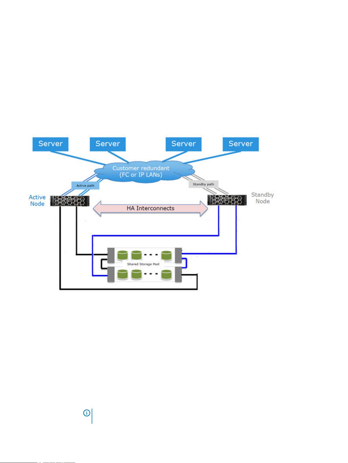
HA architecture
HA functionality is available for both IP and FC connections. Both nodes must have access to the
same IP networks, FC SANs, and hosts in order to achieve high availability for the environment.
Over IP networks, HA uses a floating IP address to provide data access to the active node of the
HA pair, regardless of which physical node is the active node.
Over FC SANs, HA uses NPIV to move the FC WWNs between nodes, allowing the FC initiators to
re-establish connections after a failover.
Figure 1 on page 22 shows the HA architecture.
Figure 1 HA architecture
Random I/O handling
The random I/O optimizations included in DD OS provide improved performance for applications
and use cases that generate larger amounts of random read and write operations than sequential
read and write operations.
DD OS is optimized to handle workloads that consist of random read and write operations, such as
virtual machine instant access and instant restore, and incremental forever backups generated by
applications such as Avamar. These optimizations:
l
Improve random read and random write latencies.
l
Improve user IOPS with smaller read sizes.
l
Support concurrent I/O operations within a single stream.
l
Provide peak read and write throughput with smaller streams.
Note:
The maximum random I/O stream count is limited to the maximum restore stream
count of a protection system.
22 Dell EMC DD OS Administration Guide
Page 23

The random I/O enhancements allow the protection system to support instant access/instant
restore functionality for backup applications such as Avamar and Networker.
System administrator access
System administrators can access the system for configuration and management using a command
line interface (CLI) or a graphical user interface (GUI).
l
DD OS CLI - A command-line interface that is available through a serial console or through
Ethernet connections using SSH or Telnet. CLI commands enable initial system configuration,
changes to individual system settings, and display of system operation status.
l
DD System Manager - A browser-based graphical user interface that is available through
Ethernet connections. Use DD System Manager to perform initial system configuration, modify
the system configuration, display system and component status, and generate reports and
charts.
Note: Some DD hardware models support access using a keyboard and monitor attached
directly to the system.
Licensed features
Feature licenses allow you to purchase only those features you intend to use. Some examples of
features that require licenses are DD Boost, and capacity on demand (storage capacity increases).
Consult with your sales representative for information on purchasing licensed features.
System Features and Integration
Table 3
Features requiring licenses
Feature Name License Name in
Software
DD ArchiveStore ARCHIVESTORE Licenses systems for archive use, such as file and
DD Boost DDBOOST Enables the use of a system with qualified backup
DD Capacity on
Demand
Cloud Tier CLOUDTIER-
DD Encryption ENCRYPTION Allows data on system drives or external storage
CONTROLLERCOD
CAPACITY
Description
email archiving, file tiering, and content and
database archiving.
software. The online compatibility guide available
at https://compatibilityguide.emc.com:8080/
CompGuideApp/ provides the list of qualified
applications. The managed file replication (MFR)
feature of DD Boost also requires the DD
Replicator license.
Enables an on-demand capacity increase for a DD
system that is not at its maximum supported
capacity.
Enables a system to move data from the active
tier to low-cost, high-capacity object storage in
the public, private, or hybrid cloud for long-term
retention.
to be encrypted while being saved and locked
when moving the system to another location.
DD Expansion Storage EXPANDED-
STORAGE
Allows system storage to be expanded beyond
the level provided in the base system.
Dell EMC DD OS Administration Guide 23
Page 24

System Features and Integration
Table 3 Features requiring licenses (continued)
Feature Name License Name in
Software
DD I/OS (for IBM i
operating
environments)
DD Replicator REPLICATION Adds DD Replicator for replication of data from
DD Retention Lock
Compliance Edition
DD Retention Lock
Governance Edition
DD Shelf CapacityActive Tier
DD Storage Migration STORAGE-
I/OS An I/OS license is required when DD VTL is used
RETENTIONLOCKCOMPLIANCE
RETENTIONLOCKGOVERNANCE
CAPACITYACTIVE
MIGRATION-FORDATADOMAINSYSTEMS
Description
to backup systems in the IBM i operating
environment. Apply this license before adding
virtual tape drives to libraries.
one protection system to another. A license is
required on each system.
Meets the strictest data retention requirements
from regulatory standards such as SEC17a-4.
Protects selected files from modification and
deletion before a specified retention period
expires.
Enables a system to expand the active tier
storage capacity to an additional enclosure or a
disk pack within an enclosure.
Enables migration of data from one enclosure to
another to support replacement of older, lowercapacity enclosures.
DD Virtual Tape
Library (DD VTL)
High Availability HA-ACTIVE-
SSD Cache SSD-CAPACITY Enables the SSD cache feature on DD6300,
VTL Enables the use of a protection system as a
virtual tape library over a Fibre Channel network.
This license also enables the NDMP Tape Server
feature, which previously required a separate
license.
Enables the High Availability feature in an Active-
PASSIVE
Standby configuration. You only need to purchase
one HA license; the license runs on the active
node and is mirrored to the standby node.
DD6800, DD9300, DD9500, and DD9800
systems. This license is not required to use the
SSD cache feature on DD6900, DD9400, and
DD9900 systems.
Storage environment integration
Protection systems integrate easily into existing data centers.
l
All protection systems can be configured as storage destinations for leading backup and
archiving applications using NFS, CIFS, DD Boost, or DD VTL protocols.
l
Search for
applications that work with the different configurations.
l
Multiple backup servers can share a single protection system.
compatibility documents
at https://support.emc.com for information on the
24 Dell EMC DD OS Administration Guide
Page 25
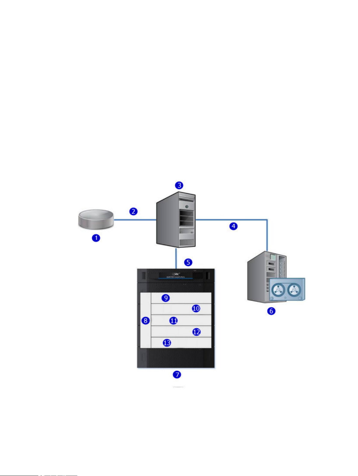
System Features and Integration
l
A single protection system can handle multiple simultaneous backup and restore operations.
l
Multiple protection systems can be connected to one or more backup servers.
For use as a backup destination, a protection system can be configured either as a disk storage
unit with a file system that is accessed through an Ethernet connection or as a virtual tape library
that is accessed through a Fibre Channel connection. The DD VTL feature enables protection
systems to be integrated into environments where backup software is already configured for tape
backups to minimize disruption.
Configuration is performed both in the DD OS, as described in the relevant sections of this guide,
and in the backup application, as described in the backup application’s administrator guides and in
application-related guides and tech notes.
All backup applications can access the protection system as either an NFS or a CIFS file system on
the disk device.
The following figure shows a protection system integrated into an existing basic backup
configuration.
Figure 2 Protection system integrated into a storage environment
1. Primary storage
2. Ethernet
3. Backup server
4. SCSI/Fibre Channel
5. Ethernet or Fibre Channel connection
6. Tape system
Dell EMC DD OS Administration Guide 25
Page 26

System Features and Integration
Figure 2 Protection system integrated into a storage environment (continued)
As shown in Figure 2 on page 25, data flows to the protection system through an Ethernet or Fibre
Channel connection. Immediately, the data verification processes begin and are continued while
the data resides on the system. In the file system, the DD OS Global Compression algorithms
deduplicate and compress the data for storage. Data is then sent to the disk RAID subsystem.
When a restore operation is required, data is retrieved from storage, decompressed, verified for
consistency, and transferred via Ethernet to the backup servers using Ethernet (for NFS, CIFS,
DD Boost), or using Fiber Channel (for DD VTL and DD Boost).
The DD OS accommodates relatively large streams of sequential data from backup software and is
optimized for high throughput, continuous data verification, and high compression. It also
accommodates the large numbers of smaller files in nearline storage (DD ArchiveStore).
Protection system performance is best when storing data from applications that are not
specifically backup software under the following circumstances.
l
Data is sent to the protection system as sequential writes (no overwrites).
l
Data is neither compressed nor encrypted before being sent to the protection system.
7. Protection system
8. DD OS management layer
9. NFS export/CIFS share/DD VTL pool/DD Boost storage unit
10. DD OS data verification
11. DD OS file system
12. DD OS global deduplication and compression
13. DD OS RAID protection
26 Dell EMC DD OS Administration Guide
Page 27

CHAPTER 2
Getting Started
This chapter includes:
l
Dell EMC DD System Manager overview............................................................................... 28
l
Logging in and out of DD System Manager............................................................................28
l
The DD System Manager interface........................................................................................ 31
l
Configuring the system with the configuration wizard...........................................................34
l
Configure NTP...................................................................................................................... 46
l
Command line interface.........................................................................................................47
l
Logging into the CLI.............................................................................................................. 47
l
CLI online help guidelines...................................................................................................... 48
Dell EMC DD OS Administration Guide
27
Page 28

Getting Started
Dell EMC DD System Manager overview
DD System Manager is a browser-based GUI for managing a single system from any location. DD
System Manager provides a single, consolidated management interface that enables you to
configure and monitor many of the system features and settings.
Note: PowerProtect DD Management Center (DDMC) enables you to manage multiple
systems from a single browser window.
DD System Manager provides real-time graphs and tables that enable you to monitor the status of
system hardware components and configured features.
Additionally, a command set that performs all system functions is available to users through the
CLI. Commands configure system settings and display system hardware status, feature
configuration, and operation.
The command-line interface is available through a serial console or through an Ethernet
connection using SSH, Telnet, or serial over LAN (SOL).
Note: Some systems support access using a keyboard and monitor attached directly to the
system.
DD OS Software Versions
DD OS software releases have two public statuses, indicating the number of installed systems
running the version.
l
General Availability releases have completed internal QA Testing and are available for
installation in production environments.
l
Directed Availability - Controlled (Directed Availability) releases are carefully controlled
access releases, directed to a small number of installations. Customers may request to be
qualified for access to these releases.
l
Target Code -Dell EMC recommends that all systems upgrade to the DD OS target code
within a release family as soon as practical.
Note:
There is only one Target Code release in a given family. Target Code releases have
met the installation and run-time hours and quality metrics to indicate that they are stable
and have no problems that would affect most customers. For some release families, there
may be no target code identified, due to limited customer uptake, quality issues, or other
considerations.
Upgrading between families may have product compatibility considerations, and a careful review of
product compatibility should precede any upgrade to a new release family.
Logging in and out of DD System Manager
DD System Manager provides a single, consolidated management interface that enables you to
configure and monitor many of the system features and settings Use a browser to log in to DD
System Manager.
About this task
When connecting to DD System Manager from a web browser, all HTTP connections automatically
redirect to HTTPS.
Note:
For information about managing user permissions, see the KB article
Permissions on the Data Domain system
support.emc.com/kb/181533.
28 Dell EMC DD OS Administration Guide
Managing User
, available from the Online Support website, at https://
Page 29

Procedure
1. Open a web browser and enter the IP address or hostname to connect to DD System
Manager. It must be one of the following:
l
A fully qualified domain name (for example, http://dd01.example.com)
l
A hostname (http://dd01)
l
An IP address (http://10.5.50.5)
Note: DD System Manager uses HTTP port 80 and HTTPS port 443. If your system is
behind a firewall, you may need to enable port 80 if using HTTP, or port 443 if using
HTTPS to reach the system. The port numbers can be easily changed if security
requirements dictate.
Note: If DD System Manager is unable to launch from any web browser, the displayed
error message is "The GUI Service is temporarily unavailable. Please refresh your
browser. If the problem persists, contact support for assistance." SSH can be used to
login to the system and can run all commands.
If you have not upgraded the DD OS but still encounter this GUI error, use the following
procedure:
a. Close the web browser session on the system with the reported error.
Getting Started
b. Run these commands in sequence:
l
adminaccess disable http
l
adminaccess disable https
l
adminaccess enable http
l
adminaccess enable https
c. Wait 5 minutes to allow the http and https services to start completely.
d. Open a web browser, and connect to DD System Manager.
If you see this GUI issue after a DD OS upgrade, use the following procedure:
a. Close the web browser session on the system with the reported error.
b. Run these commands in sequence:
l
adminaccess disable http
l
adminaccess disable https
l
adminaccess certificate generate self-signed-cert
l
adminaccess enable http
l
adminaccess enable https
a. Wait 5 minutes to allow the http and https services to start completely.
b. Open a web browser, and connect to DD System Manager.
2. For HTTPS secure login, click Secure Login.
Secure login with HTTPS requires a digital certificate to validate the identity of the DD OS
system and to support bi-directional encryption between DD System Manager and a
browser. DD OS includes a self-signed certificate, and DD OS allows you to import your own
certificate.
3. Enter your assigned username and password.
Dell EMC DD OS Administration Guide 29
Page 30

Getting Started
l
For physical systems the default password is the system serial number.
l
For PowerProtect DD Virtual Edition (DD VE) instances the default password is
changeme.
4. Click Log In.
If this is the first time you have logged in, the Home view is displayed in the Information
panel.
Note: If you enter an incorrect password 4 consecutive times, the system locks out the
specified username for 120 seconds. The login count and lockout period are configurable
and might be different on your system.
Note: If this is the first time you are logging in, you might be required to change your
password. If the system administrator has configured your username to require a
password change, you must change the password before gaining access to DD System
Manager.
If you forget the sysadmin password after changing it, contact Dell EMC Support.
5. To log out, click the log out button in the DD System Manager banner.
When you log out, the system displays the log in page with a message that your log out is
complete.
Log in with certificate using CAC/PIV card
Log in to DD System Manager with a certificate issued by a Certificate Authority (CA).
Before you begin
l
You must have authorization privileges on the protection system, and the protection system
must trust the CA certificate. Your username must be specified in the common-name field in
the certificate.
l
You must have a user account on the protection system. You can be either a local user or a
name service user (NIS/AD). For a name service user, your group-to-role mapping must be
configured on the protection system.
Procedure
1. Use the following CLI command to import the public key from the CA that issued the
certificate: adminaccess certificate import ca application login-auth.
2. Load the user certificate in PKCS12 format in your browser from the CAC/PIV card after
swiping CAC/PIV card against a card reader which interacts with the browser .
Once the CA certificate is trusted by the protection system, a Log in with certificate link is
visible on the HTTPS login screen.
3. Click Log in with certificate, and choose the user certificate from the list of certificates
that are prompted by the browser.
Results
The system validates the user certificate against the trust store. Based on authorization privileges
associated with your account, a System Manager session is created for you.
30 Dell EMC DD OS Administration Guide
Page 31

Logging in using single sign-on (SSO)
As an alternative to logging in using a local username and password, you can log in to DD System
Manager with a username and password from a supported SSO provider .
Before you begin
To log in using SSO, SSO must be enabled and the protection system must be registered with an
SSO provider.
About this task
Configuring SSO authentication on page 155 describes how to enable SSO authentication and
register the protection system with the SSO provider.
Procedure
1. At the login screen, click Log in with Data Protection Central.
Note: If a brand name is set on Data Protection Central (DPC), the link appears as Log
in with
2. Log in with the DPC username and password.
<DPC-brand-name>
Getting Started
.
The DD System Manager interface
The DD System Manager interface provides common elements on most pages that enable you to
navigate through the configuration and display options, and context sensitive help.
Dell EMC DD OS Administration Guide 31
Page 32

Getting Started
Page elements
The primary page elements are the banner, the navigation panel, the information panels, and
footer.
Figure 3 DD System Manager page components
1. Banner
2. Navigation panel
3. Information panels
4. Footer
Banner
The DD System Manager banner displays the program name and buttons for Refresh, Log Out,
and Help.
Navigation panel
The Navigation panel displays the highest level menu selections that you can use to identify the
system component or task that you want to manage.
The Navigation panel displays the top two levels of the navigation system. Click any top level title
to display the second level titles. Tabs and menus in the Information panel provide additional
navigation controls.
Information panel
The Information panel displays information and controls related to the selected item in the
Navigation panel, and is where you find system status information and configure a system.
Depending on the feature or task selected in the Navigation panel, the Information panel may
display a tab bar, topic areas, table view controls, and the More Tasks menu.
32 Dell EMC DD OS Administration Guide
Page 33

Getting Started
Tab bar
Tabs provide access to different aspects of the topic selected in the Navigation panel.
Topic areas
Topic areas divide the Information panel into sections that represent different aspects of the topic
selected in the Navigation panel or parent tab.
For high-availability (HA) systems, the HA Readiness tab on the System Manager dashboard
indicates whether the HA system is ready to fail over from the active node to the standby node.
You can click on HA Readiness to navigate to the High Availability section under HEALTH.
Working with table view options
Many of the views with tables of items contain controls for filtering, navigating, and sorting the
information in the table.
How to use common table controls:
l
Click the diamond icon in a column heading to reverse the sort order of items in the column.
l
Click the < and > arrows at the bottom right of the view to move forward or backward through
the pages. To skip to the beginning of a sequence of pages, click |<. To skip to the end, click
>|.
l
Use the scroll bar to view all items in a table.
l
Enter text in the Filter By box to search for or prioritize the listing of those items.
l
Click Update to refresh the list.
l
Click Reset to return to the default listing.
Footer
Help buttons
More Tasks menu
Some pages provide a More Tasks menu at the top right of the view that contains commands
related to the current view.
The DD System Manager footer displays important information about the management session.
The footer lists the following information.
l
System hostname.
l
DD OS version
l
Selected system model number.
l
User name and role for the current logged in user.
Help buttons display a ? and appear in the banner, in the title of many areas of the Information
panel, and in many dialog boxes. Click the help button to display a help window related to the
current feature you are using.
The help window provides a contents button and navigation button above the help. Click the
contents button to display the guide contents and a search button that you can use to search the
help. Use the directional arrow buttons to page through the help topics in sequential order.
End User License Agreement
To view the End User License Agreement (EULA), select Maintenance > System > View EULA.
Dell EMC DD OS Administration Guide 33
Page 34

Getting Started
Configuring the system with the configuration wizard
The protection system provides two wizards: a DD System Manager configuration wizard and a
Command Line Interface (CLI) configuration wizard. The configuration wizards guide you through
a simplified configuration of your system to get your protection system operating quickly.
About this task
After you complete the basic configuration with a wizard, you can use additional configuration
controls in DD System Manager and the CLI to further configure your system.
Note: The following procedure describes how to start and run the DD System Manager
configuration wizard after the initial configuration of your protection system. For instructions
on running the configuration wizards at system startup, see the
system model.
Note: To configure your system for HA, use the CLI Configuration Wizard. For more
information, see the
Procedure
1. Select Maintenance > System > Configure System.
2. Use the controls at the bottom of the Configuration Wizard dialog box to select which
features to configure and to advance through the wizard. To display help for a feature, click
the help icon (question mark) in the lower left corner of the dialog box.
Installation Guide
for the HA-capable system.
Installation Guide
for your
License page
The License page displays all installed licenses. Click Yes to add, modify, or delete a license, or
click No to skip license installation.
License Configuration
The Licenses Configuration section enables you add, modify, or delete licenses from a license file.
DD OS 6.0 and later supports licensing via the Electronic License Management System (ELMS),
which enables you to include multiple features in a single license file upload.
When using the Configuration Wizard on a system with no licenses configured, select the license
type from the drop-down, and click the ... button. Browse to the directory where the license file
resides, and select it for upload to the system.
Table 4
Item Description
Add Licenses Select this option to add licenses from a license file.
Replace Licenses If licenses are already configured the Add Licenses selection
Delete Licenses Select this option to delete licenses already configured on the
License Configuration page values
changes to Replace Licenses. Select this option to replace
the licenses already added.
system.
34 Dell EMC DD OS Administration Guide
Page 35

Network
The Network section enables you to configure the network settings. Click Yes to configure the
network settings, or click No to skip network configuration.
Network General page
The General page enables you to configure network settings that define how the system
participates in an IP network.
To configure these network settings outside of the configuration wizard, select Hardware >
Ethernet.
Table 5 General page settings
Item Description
Obtain Settings using DHCP Select this option to specify that the system collect network
Getting Started
settings from a Dynamic Host Control Protocol (DHCP)
server. When you configure the network interfaces, at least
one of the interfaces should be configured to use DHCP.
Manually Configure Select this option to use the network settings defined in the
Host Name Specifies the network hostname for this system.
Domain Name Specifies the network domain to which this system belongs.
Default IPv4 Gateway Specifies the IPv4 address of the static default gateway to
Default IPv6 Gateway Specifies the IPv6 address of the static default gateway to
Network Interfaces page
The Interfaces page enables you to configure network settings that define how each interface
participates in an IP network.
To Configure these network settings outside of the configuration wizard, select Hardware >
Ethernet > Interfaces.
Settings area of this page.
Note: If you choose to obtain the network settings
through DHCP, you can manually configure the hostname
at Hardware > Ethernet > Settings or with the net
set hostname command. You must manually configure
the host name when using DHCP over IPv6.
which the system will forward network requests when there
is no route entry for the destination system.
which the system will forward network requests when there
is no route entry for the destination system.
Table 6
Interfaces page settings
Item Description
Interface Lists the interfaces available on your system.
Enabled Shows whether each interface is enabled (checkbox
selected) or disabled (not selected). Click the checkbox to
toggle the interface between the enabled and disabled states.
Dell EMC DD OS Administration Guide 35
Page 36

Getting Started
Table 6 Interfaces page settings (continued)
Item Description
DHCP Shows the current Dynamic Host Control Protocol (DHCP)
IP Address Specifies an IPv4 or IPv6 address for an interface on this
Netmask Specifies the network mask for this system. To configure the
Link Displays whether the Ethernet link is active (Yes) or not (No).
Network DNS page
The DNS page enables you to configure IP addresses for DNS servers to convert hostnames to IP
addresses and vice versa.
configuration for each interface. Select v4 for IPv4 DHCP
connections, v6 for IPv6 connections, or no to disable DHCP.
system. To configure the IP address, you must set DHCP to
No.
network mask, you must configure a static IP address and set
DHCP to No.
To Configure these network settings outside of the configuration wizard, select Hardware >
Ethernet > Settings.
Table 7
DNS page settings
Item Description
Obtain DNS using DHCP. Select this option to specify that the system collect DNS IP
addresses from a Dynamic Host Control Protocol (DHCP)
server. When you configure the network interfaces, at least
one of the interfaces should be configured to use DHCP.
Manually configure DNS list. Select this option when you want to manually enter DNS
server IP addresses.
Add (+) button Click this button to display a dialog box in which you can add
a DNS IP address to the DNS IP Address list. You must select
Manually configure DNS list before you can add or delete
DNS IP addresses.
Delete (X) button Click this button to delete a DNS IP address from the DNS IP
Address list. You must select the IP address to delete before
this button is enabled. You must also select Manually
configure DNS list before you can add or delete DNS IP
addresses.
IP Address Checkboxes Select a checkbox for a DNS IP address that you want to
delete. Select the DNS IP Address checkbox when you want
to delete all IP addresses. You must select Manually
configure DNS list before you can add or delete DNS IP
addresses.
36 Dell EMC DD OS Administration Guide
Page 37

File System
The File System section allows you to create the file system, and configure Active Tier, Cache
Tier, and Cloud Tier storage. Each has a separate wizard page. The configuration pages cannot be
accessed if the file system is already created.
Cache Tier storage is part of the configuration wizard for the following system models that come
with SSDs for cache storage:
l
DD6900
l
DD9400
l
DD9900
Cloud Tier storage is optional, and you can configure it later. The file system must be disabled to
configure Cloud Tier storage.
Anytime you display the File System section when the File System has not been created, the
system displays an error message. Continue with the procedure to create the file system.
Configure storage tier pages
The configure storage tier pages enable you to configure storage for each licensed tier on the
system, Active Tier, Cache Tier, and Cloud Tier. Each tier has a separate wizard page. The storage
tier configuration pages cannot be accessed through the wizard if the file system is already
created.
Getting Started
Systems that use 8 TB disks require a certain number of disks installed in the disk shelves in order
to configure Active Tier and Cloud Tier storage. The minimum disk requirements are:
Note:
Systems that are not listed in this table do not support 8 TB disks, and are not subject to
this requirement.
System Minimum disk packs
required for Active Tier
(number of disks)
DD6900 N/A 2 packs (30 disks)
DD9400 4 packs (60 disks) 4 packs (60 disks)
DD9900 8 packs (120 disks) 5 packs (75 disks)
Minimum disk packs
required for Cloud Tier
(number of disks)
Configure Active Tier
The Configure Active Tier section allows you to configure the Active Storage Tier devices. The
Active Tier is where back up data resides. To add storage to the Active Tier, select one or more
devices and add them to the tier. You can add storage devices up to the capacity licenses installed.
Note:
The DD3300 system requires 4 TB devices for the Active Tier.
Table 8 Addable Storage
Item Description
ID (Device in DDVE) The disk identifier, which can be any of the following.
l
The enclosure and disk number (in the form Enclosure
Slot, or Enclosure Pack for DS60 shelves)
l
A device number for a logical device such as those used by
DD VTL and vDisk
Dell EMC DD OS Administration Guide 37
Page 38

Getting Started
Table 8 Addable Storage (continued)
Item Description
l
A LUN
Disks The disks that comprise the disk pack or LUN. This does not
apply to DDVE instances.
Model The type of disk shelf. This does not apply to DDVE instances.
Disk Count The number of disks in the disk pack or LUN. This does not
apply to DDVE instances.
Disk Size (Size in DDVE) The data storage capacity of the disk.
a
Failed Disks Failed disks in the disk pack or LUN. This does not apply to
DDVE instances.
Type SCSI. This only applies to DDVE instances.
a.
The DD OS convention for computing disk space defines one gibibyte as 230 bytes, giving a
different disk capacity than the manufacturer’s rating.
Table 9 Active Tier values
Item Description
ID (Device in DDVE) The disk identifier, which can be any of the following.
l
The enclosure and disk number (in the form Enclosure
Slot, or Enclosure Pack for DS60 shelves). This does not
apply to DDVE instances.
l
A device number for a logical device such as those used by
DD VTL and vDisk
l
A LUN
Disks The disks that comprise the disk pack or LUN. This does not
apply to DDVE instances.
Model The type of disk shelf. This does not apply to DDVE instances.
Disk Count The number of disks in the disk pack or LUN. This does not
apply to DDVE instances.
Disk Size (Size in DDVE) The data storage capacity of the disk.
a
Failed Disks Failed disks in the disk pack or LUN. This does not apply to
DDVE instances.
Configured New or existing storage. This does not apply to DDVE
instances.
Type SCSI. This only applies to DDVE instances.
a.
The DD OS convention for computing disk space defines one gibibyte as 230 bytes, giving a
different disk capacity than the manufacturer’s rating.
Configure Cache Tier
The Configure Cache Tier section allows you to configure the Cache Storage Tier devices. The
Cache Tier is where metadata cached with the Metadata on Flash feature resides. To add storage
38 Dell EMC DD OS Administration Guide
Page 39

Getting Started
to the Cache Tier, select one or more devices and add them to the tier. You can add storage
devices up to the capacity licenses installed.
Note: DD6900, DD9400, and DD9900 systems do not require a license for Cache Tier storage.
Table 10 Addable Storage
Item Description
ID The disk identifier, which can be any of the following.
l
The enclosure and disk number (in the form Enclosure
Slot, or Enclosure Pack for DS60 shelves)
l
A device number for a logical device such as those used by
DD VTL and vDisk
l
A LUN
Disk Size (Size in DDVE) The data storage capacity of the disk.
Type SAS-SSD
a.
The DD OS convention for computing disk space defines one gibibyte as 230 bytes, giving a
different disk capacity than the manufacturer’s rating.
a
Table 11 Cache Tier values
Item Description
ID The disk identifier, which can be any of the following.
l
The enclosure and disk number (in the form Enclosure
Slot, or Enclosure Pack for DS60 shelves). This does not
apply to DDVE instances.
l
A device number for a logical device such as those used by
DD VTL and vDisk
l
A LUN
Disk Size (Size in DDVE) The data storage capacity of the disk.
a
Type SAS-SSD
Configured New or existing storage.
a.
The DD OS convention for computing disk space defines one gibibyte as 230 bytes, giving a
different disk capacity than the manufacturer’s rating.
Configure Cloud Tier
The Configure Cloud Tier section allows you to configure the Cloud Storage Tier devices. To add
storage to the Cloud Tier, select one or more devices and add them to the tier. You can add
storage devices up to the capacity licenses installed.
Note:
The DD3300 system requires 1 TB devices for Cloud Tier.
Table 12 Addable Storage
Item Description
ID (Device in DDVE) The disk identifier, which can be any of the following.
Dell EMC DD OS Administration Guide 39
Page 40

Getting Started
Table 12 Addable Storage (continued)
Item Description
l
The enclosure and disk number (in the form Enclosure
Slot, or Enclosure Pack for DS60 shelves)
l
A device number for a logical device such as those used by
DD VTL and vDisk
l
A LUN
Disks The disks that comprise the disk pack or LUN. This does not
apply to DDVE instances.
Model The type of disk shelf. This does not apply to DDVE instances.
Disk Count The number of disks in the disk pack or LUN. This does not
apply to DDVE instances.
Disk Size (Size in DDVE) The data storage capacity of the disk.
a
License Needed The licensed capacity required to add the storage to the tier.
Failed Disks Failed disks in the disk pack or LUN. This does not apply to
DDVE instances.
Type SCSI. This only applies to DDVE instances.
a.
The DD OS convention for computing disk space defines one gibibyte as 230 bytes, giving a
different disk capacity than the manufacturer’s rating.
Table 13 Cloud Tier values
Item Description
ID (Device in DDVE) The disk identifier, which can be any of the following.
l
The enclosure and disk number (in the form Enclosure
Slot, or Enclosure Pack for DS60 shelves). This does not
apply to DDVE instances.
l
A device number for a logical device such as those used by
DD VTL and vDisk
l
A LUN
Disks The disks that comprise the disk pack or LUN. This does not
apply to DDVE instances.
Model The type of disk shelf. This does not apply to DDVE instances.
Disk Count The number of disks in the disk pack or LUN. This does not
apply to DDVE instances.
Disk Size (Size in DDVE) The data storage capacity of the disk.
a
License Used The licensed capacity consumed by the storage.
Failed Disks Failed disks in the disk pack or LUN. This does not apply to
Configured New or existing storage. This does not apply to DDVE
Type SCSI. This only applies to DDVE instances.
40 Dell EMC DD OS Administration Guide
DDVE instances.
instances.
Page 41

Table 13 Cloud Tier values (continued)
a.
The DD OS convention for computing disk space defines one gibibyte as 230 bytes, giving a
different disk capacity than the manufacturer’s rating.
Create File System page
The Create File System page displays the allowed size of each storage tier in the file system, and
provides a setting to automatically enable the file system after it is created.
System Settings
The System Settings section enables you to configure system passwords and email settings. Click
Yes to configure the system settings or click No to skip system settings configuration.
System Settings Administrator page
The Administrator page enables you to configure the administrator password and define how the
system communicates with the administrator.
Table 14 Administrator page settings
Getting Started
Item Description
User Name The default administrator name is
Old Password Type the old password for sysadmin.
New Password Type the new password for sysadmin.
Verify New Password Retype the new password for sysadmin.
Admin Email Specify the email address to which DD System Manager
Send Alert Notification Emails
to this address
Send Daily Alert Summary
Emails to this address
Send Autosupport Emails to
this address
System Settings Email/Location page
The Email/Location page enables you to configure the mail server name, control what system
information is sent to Dell EMC, and specify a location name to identify your system.
sysadmin
user cannot be renamed or deleted.
sends alert and autosupport email messages.
Check to configure DD System Manager to send alert
notifications to the Admin email address as alert events
occur.
Check to configure DD System Manager to send alert
summaries to the Admin email address at the end of each day.
Check to configure DD System Manager to send the Admin
user autosupport emails, which are daily reports that
document system activity and status.
. The sysadmin
Table 15
Item Description
Mail Server Specify the name of the mail server that manages emails to
Email/Location page settings
and from the system.
Dell EMC DD OS Administration Guide 41
Page 42

Getting Started
Table 15 Email/Location page settings (continued)
Item Description
Credentials Select whether or not to require credentials for the mail
server.
User Name If credentials are enabled, specify the mail server username.
Password If credentials are enabled, specify the mail server password.
Send Alert Notification Emails
to Dell EMC
Send Vendor Support
Notification Emails to Dell
EMC
Location Use this optional attribute to record the location of your
DD Boost protocol
The DD Boost settings section enables you to configure the DD Boost protocol settings. Click Yes
to configure the DD Boost Protocol settings, or click No to skip DD Boost configuration.
DD Boost Protocol Storage Unit page
The Storage Unit page enables you to configure DD Boost storage units.
To configure these settings outside of the configuration wizard, select Protocols > DD Boost >
Storage Units > + (plus sign) to add a storage unit, the pencil to modify a storage unit, or X to
delete a storage unit.
Table 16
Storage Unit page settings
Check to configure DD System Manager to send alert
notification emails to Dell EMC.
Check to configure DD System Manager to send vendor
support notification emails to Dell EMC.
system. If you specify a location, this information is stored as
the SNMP system location.
Item Description
Storage Unit The name of your DD Boost Storage Unit. You may optionally
User For the default DD Boost user, either select an existing user,
42 Dell EMC DD OS Administration Guide
change this name.
or select Create a new Local User, and enter their User name,
Password, and Management Role. This role can be one of the
following:
l
Admin role
protection system.
l
User role
own password.
l
Security role
set up security-officer configurations and manage other
security-officer operators.
l
Backup-operator role
lets you create snapshots, import and export tapes to, or
move tapes within a DD VTL.
: Lets you configure and monitor the entire
: Lets you monitor systems and change your
: In addition to user role privileges, lets you
: In addition to user role privileges,
Page 43

Table 16 Storage Unit page settings (continued)
Item Description
DD Boost Protocol Fibre Channel page
The Fibre Channel page enables you to configure DD Boost Access Groups over Fibre Channel.
To configure these settings outside of the configuration wizard, select Protocols > DD Boost >
Fibre Channel > + (plus sign) to add an access group, the pencil to modify an access group, or X
to delete an access group.
Table 17 Fibre Channel page settings
l
None role
you cannot monitor or configure a system. None is also
the parent role for the SMT tenant-admin and tenantuser roles. None is also the preferred user type for DD
Boost storage owners. Creating a new local user here
only allows that user to have the "none" role.
: Intended only for DD Boost authentication, so
Getting Started
CIFS protocol
Item Description
Configure DD Boost over Fibre
Channel
Group Name (1-128 Chars) Create an Access Group. Enter a unique name. Duplicate
Initiators Select one or more initiators. Optionally, replace the initiator
Devices The devices to be used are listed. They are available on all
Select the checkbox if you want to configure DD Boost over
Fibre Channel.
access groups are not supported.
name by entering a new one. An initiator is a backup client
that connects to the system to read and write data using the
FC (Fibre Channel) protocol. A specific initiator can support
DD Boost over FC or DD VTL, but not both.
endpoints. An endpoint is the logical target on the Data
Domain or PowerProtect system to which the initiator
connects.
The CIFS Protocol settings section enables you to configure the CIFS protocol settings. Click Yes
to configure the CIFS protocol settings, or click No to skip CIFS configuration.
The system uses the term MTree to describe directories. When you configure a directory path, DD
OS creates an MTree where the data will reside.
CIFS Protocol Authentication page
The Authentication page enables you to configure Active Directory and Workgroup for your
system.
To configure these settings outside of the configuration wizard, select Administration > Access >
Authentication.
Dell EMC DD OS Administration Guide 43
Page 44

Getting Started
Table 18 Authentication page settings
Item Description
Active Directory/Kerberos
Authentication
Workgroup Authentication Expand this panel to configure Workgroup authentication.
LDAP Authentication Expand this panel to configure LDAP authentication.
NIS Authentication Expand this panel to configure NIS authentication.
CIFS Protocol Share page
The Share page enables you to configure a CIFS protocol share name and a directory path for your
system.
To configure these settings outside of the configuration wizard, select Protocols > CIFS >
Shares > Create.
Table 19 Share page settings
Item Description
Share Name Enter a share name for the system.
Directory Path Enter a directory path for the system.
Add (+) button Click + to enter a system client, user, or group.
Pencil icon Modify a client, user, or group.
Expand this panel to enable, disable, and configure Active
Directory Kerberos authentication.
Delete (X) button Click X to delete a selected client, user. or group.
NFS protocol
The NFS Protocol settings section enables you to configure the NFS protocol settings. Click Yes
to configure the NFS protocol settings, or click No to skip NFS configuration.
The system uses the term MTree to describe directories. When you configure a directory path, DD
OS creates an MTree where the data will reside.
NFS Protocol Export page
The Export page enables you to configure an NFS protocol export directory path, network clients,
and NFSv4 referrals.
To configure these settings outside of the configuration wizard, select Protocols > NFS > Create.
Table 20
Item Description
Directory Path Enter a pathname for the export.
Add (+) button Click + to enter a system client or NFSv4 referral.
Pencil icon Modify a client or NFSv4 referral.
Export page settings
Delete (X) button Click X to delete a selected client or NFSv4 referral.
44 Dell EMC DD OS Administration Guide
Page 45

DD VTL protocol
The DD VTL Protocol settings section enables you to configure the DD Virtual Tape Library
settings. Click Yes to configure the DD VTL settings, or click No to skip DD VTL configuration.
VTL Protocol Library page
The Library page enables you to configure the DD VTL protocol settings for a library.
To configure these settings outside of the configuration wizard, select PROTOCOLS > VTL >
Virtual Tape Libraries > VTL Service > Libraries > More Tasks > Library > Create
Table 21 Library page settings
Item Description
Library Name Enter a name of from 1 to 32 alphanumeric characters.
Number of Drives Number of supported tape drives.
Drive Model Select the desired model from the drop-down list:
l
IBM-LTO-1
l
IBM-LTO-2
l
IBM-LTO-3
l
IBM-LTO-4
l
IBM-LTO-5 (default)
l
HP-LTO-3
l
HP-LTO-4
Getting Started
Number of Slots Enter the number of slots per library:
l
Up to 32,000 slots per library
l
Up to 64,000 slots per system
l
This should be equal to, or greater than, the number of drives.
Number of CAPs (Optional) Enter the number of cartridge access ports (CAPs):
l
Up to 100 CAPs per library
l
Up to 1000 CAPs per system
Changer Model Name Select the desired model from the drop-down list:
l
L180 (default)
l
RESTORER-L180
l
TS3500
l
I2000
l
I6000
l
DDVTL
Starting Barcode Enter the desired barcode for the first tape, in the format
A990000LA.
Dell EMC DD OS Administration Guide 45
Page 46

Getting Started
Table 21 Library page settings (continued)
Item Description
Tape Capacity (Optional) Enter the tape capacity. If not specified, the capacity is
VTL Protocol Access Group page
The Access Group page enables you to configure DD VTL protocol settings for an access group.
To configure these settings outside of the configuration wizard, select PROTOCOLS > VTL >
Access Groups > Groups > More Tasks > Group > Create.
Table 22 Access Group page settings
Item Description
Group Name Enter a unique name of from 1 - 128 characters. Duplicate access groups
Initiators Select one or more initiators. Optionally, replace the initiator name by
derived from the last character of the barcode.
are not supported.
entering a new one. An initiator is a backup client that connects to a
system to read and write data using the Fibre Channel (FC) protocol. A
specific initiator can support DD Boost over FC or DD VTL, but not both.
Devices The devices (drives and changer) to be used are listed. These are
available on all endpoints. An endpoint is the logical target on the
protection system to which the initiator connects.
Configure NTP
NTP is not part of the configuration wizard, but it is helpful to configure it after the completion of
the configuration wizard to keep the protection system time synchronized with other systems in
your environment.
Managing time and date settings
The Time and Date Settings tab enables you to view and configure the system time and date or
configure the Network Time Protocol to set the time and date.
Before you begin
When using active directory mode for CIFS access, the system clock time can differ by no more
than five minutes from that of the domain controller.
Procedure
1. To view the current time and date configuration, select Administration > Settings > Time
and Date Settings.
The Time and Date Settings page presents the current system date and time, shows
whether NTP is enabled or not, and lists the IP addresses or host names of configured NTP
servers.
2. To change the configuration, select More Tasks > Configure Time Settings.
The Configure Time Settings dialog box appears.
46 Dell EMC DD OS Administration Guide
Page 47

Getting Started
3. In the Time Zone list, select the time zone where the system resides.
4. To manually set the time and date, select None, type the date in the Date box, and select
the time in the Time lists.
5. To use NTP to synchronize the time, select NTP and set how the NTP server is accessed.
l
To use DHCP to automatically select a server, select Obtain NTP Servers using DHCP.
l
To configure an NTP server IP address, select Manually Configure, add the IP address
of the server, and click OK.
WARNING When the system is configured for Active Directory authentication, it uses an
alternate mechanism to sync time with the domain controller. To avoid time sync
conflicts, do not enable NTP when the system is configured for Active Directory
authentication.
6. Click OK.
7. If you changed the time zone, you must reboot the system:
a. Select Maintenance > System.
b. Click Reboot System.
c. Click OK to confirm.
Command line interface
The command line interface (CLI) is a text-driven interface that can be used instead of or in
addition to DD System Manager. Most management tasks can be performed in DD System
Manager or with the CLI. In some cases, the CLI offers configuration options and reports that are
not yet supported in DD System Manager.
Any protection system command that accepts a list, such as a list of IP addresses, accepts entries
separated by commas, by spaces, or both.
The Tab key can be used to do the following.
l
Complete a command entry when that entry is unique. Tab completion is supported for all
keywords. For example, entering syst Tab shTab st Tab displays the command system
show stats.
l
Show the next available option, if you do not enter any characters before pressing the Tab key.
l
Show partial matched tokens or complete a unique entry, if you enter characters before
pressing the Tab key.
The
DD OS Command Reference Guide
help is available and provides the complete syntax for each command.
Logging into the CLI
You can access the CLI by using a direct connection to the protection system or by using an
Ethernet connection through SSH or Telnet. By default, SSH is enabled and Telnet is disabled.
provides information for each of the CLI commands. Online
Before you begin
To use the CLI, you must establish a local or remote connection to the protection system using one
of the following methods.
l
If you are connecting through a serial console port on the system, connect a terminal console
to the port and use the communication settings: 115200 baud, 8 data bits, no parity, and 1 stop
bit.
Dell EMC DD OS Administration Guide 47
Page 48

Getting Started
l
If the system supports keyboard and monitor ports, connect a keyboard and monitor to those
ports.
l
If you are connecting through Ethernet, connect a computer with SSH or Telnet client
software to an Ethernet network that can communicate with the system.
Procedure
1. If you are using an SSH or Telnet connection to access the CLI, start the SSH or Telnet
client and specify the IP address or host name of the protection system.
For information on initiating the connection, see the documentation for the client software.
The system prompts you for a username.
2. When prompted, enter your protection system username or sysadmin, the default
username.
3. When prompted, enter the password for the specified username.
The following example shows SSH login to a system named
client software.
# ssh -l sysadmin mysystem.mydomain.com
DD9900-157.dellemc.com
DD OS
Password:
CLI online help guidelines
The CLI displays two types of help: syntax-only help and command-description help, which
includes the command syntax. Both types of help offer features that enable you reduce the time it
takes to find the information you need.
The following guidelines describe how to use syntax-only help.
l
To list the top-level CLI commands, enter a question mark (?), or type help or man at the
prompt.
l
To list all forms of a top-level command, enter the command with no options at the prompt or
enter
command
l
To list all commands that use a specific keyword, enter help
keyword
.
For example, ? password displays all system commands that use the password argument.
?.
mysystem
keyword
using SSH
, man
keyword
, or ?
The following guidelines describe how to use command-description help.
l
To list the top-level CLI commands, enter a question mark (?), or type help or man at the
prompt.
l
To list all forms of a top-level command with an introduction, enter help
command
l
The end of each help description is marked END. Press Enter to return to the CLI prompt.
l
When the complete help description does not fit in the display, the colon prompt (:) appears at
, or ?
the bottom of the display. The following guidelines describe what you can do when this prompt
appears.
n
To move through the help display, use the up and down arrow keys.
48 Dell EMC DD OS Administration Guide
command
command
, man
.
Page 49

Getting Started
n
To quit the current help display and return to the CLI prompt, press q.
n
To display help for navigating the help display, press h.
n
To search for text in the help display, enter a slash character (/) followed by a pattern to
use as search criteria and press Enter. Matches are highlighted.
Dell EMC DD OS Administration Guide 49
Page 50

Getting Started
50 Dell EMC DD OS Administration Guide
Page 51

CHAPTER 3
Managing the Protection System
This chapter includes:
l
System management overview..............................................................................................52
l
Restarting a protection system............................................................................................. 53
l
Powering a protection system on or off ............................................................................... 53
l
System upgrade management............................................................................................... 55
l
Managing electronic licenses.................................................................................................62
l
Protection system storage management............................................................................... 63
l
Network connection management..........................................................................................71
l
System passphrase management.......................................................................................... 92
l
Configuring mail server settings............................................................................................ 93
l
Managing system properties................................................................................................. 94
l
SNMP management.............................................................................................................. 94
l
Autosupport report management......................................................................................... 102
l
Support bundle management............................................................................................... 106
l
Coredump management....................................................................................................... 107
l
Alert notification management.............................................................................................108
l
Support delivery management.............................................................................................. 116
l
Log file management............................................................................................................ 118
l
Remote system power management with IPMI.................................................................... 122
l
System access management................................................................................................ 127
Dell EMC DD OS Administration Guide
51
Page 52

Managing the Protection System
System management overview
DD System Manager allows you to manage the system on which DD System Manager is installed.
To support replication, DD System Manager supports the addition of systems running the previous
two versions, the current version and the next two versions as they become available. DD System
Manager supports the addition of systems up to two releases back as replication targets. The DD
OS 7.0 release includes DD OS 6.2 and DD OS 6.1.
Note: When processing a heavy load, a system might be less responsive than normal. In this
case, management commands issued from either DD System Manager or the CLI might take
longer to complete. When the duration exceeds allowed limits, a timeout error is returned,
even if the operation completed.
The following table lists the recommendations for the maximum number of user sessions supported
by DD System Manager:
Table 23 Maximum number of users supported by DD System Manager
System Model Maximum Active Users Maximum Logged In
Users
4 GB models
16 GB and greater models
a
b
a.
Includes DD2200 (4 TB)
b.
DD2200 (>7.5TB), DD6300, DD6800, DD6900, DD9300, DD9400, DD9500, DD9800, and
DD9900
Note: Initial HA system set-up cannot be configured from the DD System Manager, but the
status of a configured HA system can be viewed from DD System Manager.
HA system management overview
The HA relationship between the two nodes, one active and one standby, is setup through DD OS
CLI commands.
Initial set-up can be run on either of the two nodes but only one at a time. It is a requirement for
HA that the system interconnect and identical hardware is setup on both nodes first.
Note:
Both nodes of the HA pair are required to have identical hardware. This requirement is
validated during setup and system boot-up.
When configuring HA for the first time, the ha create command needs to be run on the node
with the license installed. To upgrade an existing system to HA by adding and a new or
unconfigured system, initiate the HA upgrade from the existing standalone system.
HA system planned maintenance
5 10
10 20
The HA architecture provides a rolling upgrade, which reduces maintenance downtime for the
upgrade.
With a rolling upgrade, the HA nodes are upgraded one at a time. The standby node is rebooted
and upgraded first. The newly upgraded standby node then takes over the active role through an
HA failover. After the failover, the second node is rebooted and assumes the role of the standby
node after the upgrade.
System upgrade operations that require data conversion cannot start until both systems are
upgraded to the same level and HA state is fully restored.
52 Dell EMC DD OS Administration Guide
Page 53

Restarting a protection system
You may be required to restart a protection system after modifying the configuration for the
change to take effect. For example, changing the time zone requires that you restart the system
before the new time zone is applied.
About this task
Procedure
1. Select Maintenance > System > Reboot System.
2. Click OK to confirm.
Powering a protection system on or off
When powering a protection system off and on, it is important that you follow the proper
procedure to preserve the file system and configuration integrity.
About this task
Do not use the chassis power switch or the IMPI Remote System Power Down feature to power
off the protection system unless the system poweroff command is unsuccessful. Using the
chassis power switch to power down the system prevents remote power control using IPMI. Using
the IMPI Remote System Power Down feature to power off the protection system does not
perform an orderly shutdown.
For HA systems, a management connection to both nodes is required.
Complete the following steps to power off a protection system.
Managing the Protection System
Procedure
1. Verify that I/O on the system is stopped.
Run the following commands:
l
cifs show active
l
nfs show active
l
system show stats view sysstat interval 2
l
system show perf
2. For HA systems, verify the health of the HA configuration.
Run the following command:
ha status
HA System Name: dd9900-ha3a.example.com
HA System Status: highly available
Node Name Node ID Role HA State
-------------------------- --------- --------- -------dd9900-ha3a-p0.example.com 0 active online
dd9900-ha3a-p1.example.com 1 standby online
-------------------------- --------- --------- --------
Note:
This output sample is from a healthy system. If the system is being shut down to
replace a failed component, the HA System Status will be degraded, and one or both
nodes will show offline for the HA State.
3. Run the alerts show current command. For HA pairs, run the command on the active
node first, and then the standby node.
Dell EMC DD OS Administration Guide 53
Page 54

Managing the Protection System
4. For HA systems, run the ha offline command if the system is in a highly available state
with both nodes online. Skip this step if the HA status is degraded.
5. Run the system poweroff command. For HA pairs, run the command on the active node
first, and then the standby node.
# system poweroff
Continue? (yes|no|?) [no]: yes
6. Remove the power cords from the power supplies on the controller or controllers.
7. Verify that the blue power LED is off on the controllers to confirm that the system is
powered down.
Once the controller is powered off, switch off any external expansion shelves (ES30, DS60,
FS15).
Power a protection system on
About this task
Restore power to the protection system when the system downtime is complete.
Procedure
1. Power on any expansion shelves before powering on the controller. Wait approximately
three minutes after all expansion shelves are turned on.
Note:
A controller is the chassis and any internal storage. A protection system refers to
the controller and any external storage.
2. Plug in the power cord for your controller, and if there is a power button on the controller,
press the power button, as shown in the
Installation Guide
for your system. For HA systems,
power on the active node first, and then the standby node.
Note:
Some protection system appliances do not have a traditional power button, and
are designed to be "always on." These devices will power up as soon as AC power is
applied.
3. For HA systems, verify the health of the HA configuration.
Run the following command:
ha status
HA System Name: dd9900-ha3a.example.com
HA System Status: highly available
Node Name Node ID Role HA State
-------------------------- --------- --------- -------dd9900-ha3a-p0.example.com 0 active online
dd9900-ha3a-p1.example.com 1 standby offline
-------------------------- --------- --------- --------
4. For HA systems, if one of the nodes displays as offline, run the ha online command on
that node to restore the HA configuration.
5. Verify the system is fully booted and the operating system is running. This can be done
through a serial connection or from an SSH session to the system. The system is up when
you can log into the system.
6. Run the alerts show current command. For HA pairs, run the command on the active
node first, and then on the standby node.
54 Dell EMC DD OS Administration Guide
Page 55

System upgrade management
To upgrade a DD OS system, you must verify that there is sufficient room for the new software on
the target system. Transfer the software to the system to be upgraded, and then start the
upgrade.
If the system uses MD5-signed certificates, regenerate the certificates with a stronger hash
algorithm during the upgrade process.
HA system upgrades
For an HA system, transfer the software to the active node and start the upgrade from the active
node. Use the floating IP address to access DD System Manager to perform software upgrades.
The upgrade process on an HA system automatically upgrades both the active and standby nodes.
Minimally disruptive upgrade
The minimally disruptive upgrade (MDU) feature lets you upgrade specific software components or
apply bug fixes without needing to perform a system reboot. Only those services that depend on
the component being upgraded are disrupted, so the MDU feature can prevent significant
downtime during certain software upgrades.
Not all software components qualify for an MDU; such components must be upgraded as part of a
regular DD OS system software upgrade. A DD OS software upgrade uses a large RPM (upgrade
bundle), which performs upgrade actions for all of the components of DD OS. MDU uses smaller
component bundles, which upgrade specific software components individually, which makes the
MDU RPM much smaller than a full DD OS RPM.
Contact Support to determine if an MDU is available for a specific issue.
Managing the Protection System
RPM signature verification
RPM signature verification validates DD OS RPMs that you download for upgrade. If the RPM has
not been tampered with, the digital signature is valid and you can use the RPM as usual. If the
RPM has been tampered with, the corruption invalidates the digital signature, and the RPM is
rejected by DD OS. An appropriate error message is displayed.
The signatures are SHA1 or MD5.
Support software
DD OS 6.1 introduced a type of software package called support software for instances where the
software packages must be signed in order to use it for the DD OS upgrade. Support software is
an MDU package created and signed by Support Engineering to address specific issues. By default,
the protection system does not allow support software to be installed on the system. Contact
Support for more information about support software.
Pre-upgrade checklists and overview
Review the items in these checklists before performing any DD OS upgrade. Doing so can simplify
the upgrade process and minimize potential difficulties.
Pre-upgrade manual tasks
CAUTION
These are tasks that you should plan to do prior to the upgrade. These tasks are not performed
automatically by any process.
Failure to perform the tasks in this section may result in an upgrade failure.
Dell EMC DD OS Administration Guide 55
Page 56

Managing the Protection System
1. Reboot the system. For HA systems, follow the reboot instructions described in Upgrade
considerations for HA systems on page 57 after performing the rest of the checks in this
section.
2. Check for current alerts; this can reveal many such disk and other hardware failures that
should be addressed prior to upgrading:
# alert show current
3. Verify the system network configuration:
# net show config
# net show hardware
4. Check whether all network interfaces are up and have appropriate IP addresses:
# net show settings
5. Check the disk states, and do not perform the upgrade if the system is low on spares or has
disks that show in the absent, failed, or reconstructing states:
# disk show state
6. Check the disk reliability, and replace any disks that have more than 50 reallocated sectors:
# disk show reliability-data
7. Check the enclosure status:
# enclosure show all
It should say “OK” for all devices.
8. Check whether the enclosure topology is correct:
# enclosure show topology
Also check whether any error appears with an asterisk (*) next to the enc.ctrl.port field. Also
check the Error Message field for any errors such as "A possible problem was
detected for this shelf controller or the cable connected to it."
9. Check that the device port mapping is correct:
# system show hardware
10. Check the link speed for connected ports:
# system show ports
11. Check the status of the file system to determine that file system is enabled and running
normally:
# filesys status
12. Check if file system cleaning is running, and if so, stop it:
# filesys clean status
# filesys clean stop
13. If replication is enabled, check its status:
# replication status
14. For a system enabled with Cloud Tier, ensure there is no data movement:
# data-movement status
# data-movement stop all
15. Check if cloud cleaning is running, and if so, stop it:
56 Dell EMC DD OS Administration Guide
Page 57

# cloud clean status
# cloud clean stop
16. Check if any backup and restore activity is in progress, and if so, stop it:
# system show stats
17. Run an Autosupport Report just prior to performing the DD OS upgrade to determine if the
system reports errors that need to be resolved before the upgrade:
# autosupport send <your_email_address>
18. If the Autosupport Report indicated issues with the system, check kern.info log, and if you
notice frequent failures in hardware, contact Support to inspect your system before you
perform the upgrade.
# log view debug/platform/kern.info
Search for the string ERROR in the log file.
Upgrade considerations for HA systems
HA systems require some unique steps before initiating the upgrade operation, and one unique
post-check after the upgrade is complete.
CAUTION Perform the manual checks described in Pre-upgrade manual tasks on page 55
before rebooting the HA system.
Managing the Protection System
When upgrading an HA system, upload the upgrade RPM package to the active node.
1. The HA system must be in a highly available state, with both nodes online before performing
the DD OS upgrade. Run the ha status command to verify the HA system state.
# ha status
HA System Name: dd9900-ha3a.example.com
HA System Status: highly available
Node Name Node ID Role HA State
-------------------------- --------- --------- -------dd9900-ha3a-p0.example.com 0 active online
dd9900-ha3a-p1.example.com 1 standby online
-------------------------- --------- --------- --------
2. Reboot the standby node (node 1).
3. Run the ha status command to verify the HA system status displays as highly
available after the standby node reboots.
4. Run the ha failover command to initiate a failover from the active node to the standby
node.
5. Run the ha status command to verify node 1 is the active node and node 0 is the standby
node.
# ha status
HA System Name: dd9900-ha3a.example.com
HA System Status: highly available
Node Name Node ID Role HA State
-------------------------- --------- --------- -------dd9900-ha3a-p0.example.com 0 standby online
dd9900-ha3a-p1.example.com 1 active online
-------------------------- --------- --------- --------
6. Reboot the standby node (node 0).
7. Run the ha status command to verify the HA system status displays as highly
available after the standby node reboots.
8. Run the ha failover command to initiate a failover from the active node to the standby
node.
Dell EMC DD OS Administration Guide 57
Page 58

Managing the Protection System
9. Run the ha status command to verify the node 0 is the active node and node 1 is the
standby node.
# ha status
HA System Name: dd9900-ha3a.example.com
HA System Status: highly available
Node Name Node ID Role HA State
-------------------------- --------- --------- -------dd9900-ha3a-p0.example.com 0 active online
dd9900-ha3a-p1.example.com 1 standby online
-------------------------- --------- --------- --------
Initiate the upgrade from the active node. DD OS automatically recognizes the HA system and
performs the upgrade procedure on both nodes. The HA upgrade runs in the following sequence:
1. The standby node is upgraded first, then reboots.
2. After the reboot is complete, the HA system initiates a failover and the standby node takes
over as the active node.
3. The original active node is upgraded, then reboots and remains as the standby node.
After both nodes are upgraded, the system does not perform another failover to return the nodes
to their original configuration.
After the upgrade procedure is complete, run the ha status command again to verify that the
system is in a highly available state, and both nodes are online.
Optionally run the ha failover command to return the nodes to the roles they were in before
the upgrade.
Automatic tasks performed prior to the upgrade
Understanding these aspects of a DD OS upgrade assures a smoother process.
DD OS performs these tasks before a system upgrade:
1. Determines whether replication initialization is in progress. If it is, the upgrade does not
proceed.
2. Inspects all the digests and signatures that are contained in .rpm file to ensure the integrity
and origin of the package. If the signature is not valid, the upgrade does not proceed.
3. Determines whether the upgrade from the old version of DD OS to the new one is permissible.
Systems running DD OS 6.1.X. or 6.2.X can upgrade directly to 7.0. This restriction is due to
the RPM signing. An upgrade is not permitted under these circumstances:
a. The upgrade target is the same version as the software already running on the system.
b. Reverting to a prior release is not allowed, such as from 7.0.0.5 to 6.2.0.10
c. The upgrade exceeds two feature families, such as from 6.0 to 7.0.
4. Determines whether any NFS mount points are unknown. If any NFS mount points are
unknown, the upgrade does not proceed.
5. Determines whether the previous upgrade, if any, completed successfully. If the previous
upgrade was unsuccessful or did not complete, the current upgrade does not proceed.
Automatic tasks performed by the upgrade script (in the .rpm file) prior to upgrade
These tests precede the actual system upgrade process. The system:
1. Determines whether two different kinds of NVRAM cards are present.
2. Checks the /ddr partition and / (root) partition sizes for space utilization.
3. Checks the OST version.
4. Determines whether the RAID metagroup is assembled. If it is not assembled, the upgrade
process does not begin.
58 Dell EMC DD OS Administration Guide
Page 59

5. Determines available space for the file system.
6. Determines whether sufficient space is available for the upgrade.
7. Checks the VTL version, if VTL is present.
8. Determines whether the file system is enabled, and if it is not enabled, enable it.
9. Determines whether VTL is enabled.
10. Checks the VTL pools to insure that they can be converted to MTrees.
11. Determines whether sufficient VTL space is available.
12. Ensures that the numbers of MTrees and VTL pools do not exceed 100.
13. Determines whether all dg0 disks are located on head unit. If not, the upgrade process does
not begin, and the problem must be addressed.
14. Determines whether the file system can be shutdown without problems. If the file system
cannot be shut down in a clean manner, the upgrade process will stop.
The upgrade process quits if it encounters a failure in any of the tasks listed.
Conditions that prevent the upgrade process
Several conditions can cause the upgrade process to be stopped:
l
The system is not in a functional state. For example:
n
Storage is functionally deficient, such as an enclosure is missing.
n
The file system did not shutdown cleanly, resulting in a core dump.
n
The previous upgrade did not complete correctly.
l
Space usage is problematic. For example:
n
The / (root) or /ddr partition is full with log files, core dumps, and so forth.
n
Insufficient storage space is available to perform the data upgrade.
l
The system is not configured correctly. For example, NFS mount points were manually created
under root.
l
Features are incompatible between the original and target versions of DD OS:
n
DD OS versions 7.0 and later do not support DD Extended Retention. Any system with DD
Extended Retention enabled cannot be upgraded to DD OS 7.0. Migrate the data to a
system running DD OS 6.1.X or 6.2.X without DD Extended Retention running. After the
migration, upgrade the DD OS 6.1.X or 6.2.X system without DD Extended Retention to DD
OS 7.0.
n
DD OS versions 7.0 and later do not support the RSA key manager for data at rest
encryption. If a DD OS 6.X system uses the RSA key manager for data at rest encryption,
upgrades to DD OS 7.0 and later are not permitted. Disable data at rest encryption to
proceed with the DD OS upgrade.
The goal of checking these conditions is to prevent any upgrade problems or file system anomalies
to occur or propagate. The conditions are also applied in upgrades involving source and destination
partner systems in replication.
Managing the Protection System
Note:
For security reasons, there is a 30-minute time limit for the upload of RPM packages for
DDMC and DD system upgrades using the DDMC GUI. If you have a slow connection from a
client machine to the DDMC and the upload takes more than 30 minutes, the connection drops
and you cannot use DDMC to upload the package.
Workaround: Use the CLI to upload the package into DDMC (for example, use SCP/PSCP from
a Unix terminal or Windows CMD).
Dell EMC DD OS Administration Guide 59
Page 60

Managing the Protection System
For DDMC upgrades, upload the package to /ddr/var/releases.
For DD System upgrades, upload the package to /ddr/var/ddr-releases.
Viewing upgrade packages on the protection system
DD System Manager allows you to view and manage up to five upgrade packages on a protection
system. Before you can upgrade a system, you must download an upgrade package from the
Online Support site to a local computer, and then upload it to the target system.
Procedure
1. Select Maintenance > System.
2. Optionally, select an upgrade package and click View Checksum to display the MD5 and
SHA256 checksums of the upgrade package.
Results
For every package stored on the system, DD System Manager displays the filename, file size, and
last modified date in the list titled: Upgrade Packages Available on
Obtaining and verifying upgrade packages
Use the DD System Manager to open a session with the Dell EMC Online Support site to select an
upgrade package for download.
<protection system>
.
About this task
Note:
You can use FTP, NFS, or SCP to copy an upgrade package to a system. DD System
Manager can manage up to 5 system upgrade packages. This limitation does not apply if you
manage system upgrade packages through a network share linked to the /ddvar/releases
directory on the protection system. There are no restrictions, other than space limitations,
when you manage the files directly in the /ddvar/releases directory. FTP is disabled by
default. To use NFS, /ddvar needs to be exported and mounted from an external host).
Procedure
1. Select Maintenance > System.
2. To obtain an upgrade package, click the Dell EMC Online Support link, click Downloads,
and use the search function to locate the package recommended for your system by
Support personnel. Save the upgrade package to the local computer.
3. Verify that there are no more than four packages listed in the Upgrade Packages Available
on
<protection system>
DD System Manager can manage up to five upgrade packages. If five packages appear in
the list, remove at least one package before uploading the new package.
4. Click Upload Upgrade Package to initiate the transfer of the upgrade package to the
protection system.
5. In the Upload Upgrade Package dialog box, click Browse to open the Choose File to
Upload dialog box. Navigate to the folder with the downloaded file, select the file, and click
Open.
6. Click OK.
list.
An upload progress dialog box appears. Upon successful completion of the upload, the
download file (with a .rpm extension) appears in the list titled: Upgrade Packages Available
on
<protection system>
60 Dell EMC DD OS Administration Guide
.
Page 61

7. To verify the upgrade package integrity, click View Checksum and compare the calculated
checksum displayed in the dialog box to the authoritative checksum on the Online Support
site.
8. To manually initiate an upgrade precheck, select an upgrade package and click Upgrade
Precheck.
Upgrading a protection system
When an upgrade package file is present on a protection system, you can use DD System Manager
to perform an upgrade using that upgrade package.
Before you begin
Read the DD OS Release Notes for the complete upgrade instructions and coverage of all the
issues that can impact the upgrade.
About this task
The procedure that follows describes how to initiate an upgrade using DD System Manager. Log
out of any CLI sessions on the system where the upgrade is to be performed before using DD
System Manager to upgrade the system.
Note: Upgrade package files use the .rpm file extension. This topic assumes that you are
updating only DD OS. If you make hardware changes, such as adding, swapping, or moving
interface cards, you must update the DD OS configuration to correspond with the hardware
changes.
Managing the Protection System
Procedure
1. Log into DD System Manager on the protection system where the upgrade is to be
performed.
Note:
As recommended in the Release Notes, reboot the protection system before
upgrading to verify that the hardware is in a clean state. If any issues are discovered
during the reboot, resolve those issues before starting the upgrade. For an MDU
upgrade, a reboot might not be needed.
2. Select Maintenance > System.
3. From the Upgrade Packages Available on
use for the upgrade.
Note:
You must select an upgrade package for a newer version of DD OS. DD OS does
not support downgrades to previous versions.
4. Click Perform System Upgrade.
The System Upgrade dialog box appears and displays information about the upgrade and a
list of users who are currently logged in to the system to be upgraded.
5. Verify the version of the upgrade package, and click OK to continue with the upgrade.
The System Upgrade dialog box displays the upgrade status and the time remaining.
When upgrading the system, you must wait for the upgrade to complete before using DD
System Manager to manage the system. If the system restarts, the upgrade might continue
after the restart, and DD System Manager displays the upgrade status after login. If
possible, keep the System Upgrade progress dialog box open until the upgrade completes or
the system restarts. A Login link appears when the upgrade is complete.
<protection system>
list, select the package to
Note:
To view the status of an upgrade using the CLI, enter the system upgrade
status command. Log messages for the upgrade are stored in /ddvar/log/debug/
Dell EMC DD OS Administration Guide 61
Page 62

Managing the Protection System
6. If the system powers down, you must remove AC power from the system to clear the prior
7. If the system does not automatically power on and there is a power button on the front
After you finish
The following requirements may apply after completing an upgrade.
l
For environments that use self-signed SHA-256 certificates, the certificates must be
regenerated manually after the upgrade process is complete and trust must be re-established
with external systems that connect to the protection system.
l
If the system shows existing or configured FC ports with missing WWPN or WWNN
information, or reports that no FC host bus adapter (HBA) driver is installed, run the
scsitarget endpoint enable all command.
platform/upgrade-error.log and /ddvar/log/debug/platform/upgradeinfo.log.
configuration. Unplug all power cables for 30 seconds, and then plug them back in. The
system powers on and restarts.
panel, press the button.
1. Run the adminaccess certificate generate self-signed-cert regenerate-ca
command to regenerate the self-signed CA and host certificates. Regenerating the
certificates breaks existing trust relationships with external systems.
2. Run the adminaccess trust add host hostname type mutual command to reestablish
mutual trust between the protection system and the external system.
Replication notes
With collection replication, no files are visible on the destination system if replication was not
finished before starting the upgrade. After the upgrade, wait until replication completes to see files
on the destination system.
Removing an upgrade package
A maximum of five upgrade packages can be uploaded to a protection system with DD System
Manager. If the system you are upgrading contains five upgrade packages, you must remove at
least one package before you can upgrade the system.
About this task
Procedure
1. Select Maintenance > System.
2. From the list titled Upgrade Packages Available on
package to remove. One package can be removed at a time.
3. Click Remove Upgrade Package.
Managing electronic licenses
Add and delete electronic licenses from the system. Refer to the applicable Release Notes for the
most up-to-date information on product features, software updates, software compatibility guides,
and information about products, licensing, and service. If DD Retention Lock Compliance is enabled
on the system, the elicense CLI commands are required to update or remove licenses because
license control in the DD SM GUI is disabled.
<protection system>
, select the
62 Dell EMC DD OS Administration Guide
Page 63

HA system license management
HA is a licensed feature, and the system licensing key is registered by following the steps to add
any other license to the DD system.
A system is configured as Active-Standby, where one node is designated "standby." Only one set
of licenses is required for both nodes. During failover, the licenses on one node will failover to the
other node.
Protection system storage management
System storage management features enable you to view the status and configuration of your
storage space, flash a disk LED to facilitate disk identification, and change the storage
configuration.
Note: All storage that is connected or used by the two-node Active-Standby HA system can be
viewed as a single system.
Using the CLI to calculate usable storage space
The following values are required to calculate the usable storage on a protection system after
accounting for RAID overhead:
l
N
= Number of disks in use in the disk group (dg).
l
C
= Capacity of each disk after formatting.
l
R
= 2 (Number of disks used for RAID 6 parity)
This calculation does not work for Cache Tier storage, because the Cache Tier disks are not RAID
protected.
Run the storage show all command to get the values for N and C.
Managing the Protection System
Figure 4
Example of storage show all command
In this example there are 14 disks in use in dg2 and each disk has a capacity of 2.7 TiB, therefore
N
=14 and C= 2.7 TiB
Use the formula (N-R) x C to get the usable capacity. In this example, the equation is (14-2) x 2.7
TiB.
12 x 2.7 TiB = 32.4 TiB, or 35.6 TB.
Note:
The calculated value may not match exactly with the output of the storage show
all command due to the way the capacity values are rounded for display. The disk show
hardware command displays the disk capacity with additional decimal places.
Dell EMC DD OS Administration Guide 63
Page 64

Managing the Protection System
Viewing system storage information
The storage status area shows the current status of the storage, such as Operational or NonOperational, and the storage migration status. Below the Status area are tabs that organize how
the storage inventory is presented.
Procedure
1. To display the storage status, select Hardware > Storage.
2. If an alerts link appears after the storage status, click the link to view the storage alerts.
3. If the Storage Migration Status is Not licensed, you can click Add License to add the license
for this feature.
Overview tab
The Overview tab displays information for all disks in the protection system organized by type. The
categories that display are dependent on the type of storage configuration in use.
The Overview tab lists the discovered storage in one or more of the following sections.
l
Active Tier
Disks in the Active Tier are currently marked as usable by the file system. Disks are listed in
two tables, Disks in Use and Disks Not in Use.
l
Cache Tier
SSDs in the Cache Tier are used for caching metadata. The SSDs are not usable by the file
system. Disks are listed in two tables, Disks in Use and Disks Not in Use.
l
Cloud Tier
Disks in the Cloud Tier are used to store the metadata for data that resides in cloud storage.
The disks are not usable by the file system. Disks are listed in two tables, Disks in Use and
Disks Not in Use.
l
Addable Storage
For systems with optional enclosures, this section shows the disks and enclosures that can be
added to the system.
l
Failed/Foreign/Absent Disks (Excluding Systems Disks)
Shows the disks that are in a failed state; these cannot be added to the system Active or
Retention tiers.
l
Systems Disks
Shows the disks where the DD OS resides when the protection system controller does not
contain data storage disks.
l
Migration History
Shows the history of migrations.
Each section heading displays a summary of the storage configured for that section. The summary
shows tallies for the total number of disks, disks in use, spare disks, reconstructing spare disks,
available disks, and known disks.
Click a section plus (+) button to display detailed information, or click the minus (-) button to hide
the detailed information.
Table 24
Item Description
Disk Group The name of the disk group that was created by the file
64 Dell EMC DD OS Administration Guide
Disks In Use column label descriptions
system (for example, dg1).
Page 65

Managing the Protection System
Table 24 Disks In Use column label descriptions (continued)
Item Description
State The status of the disk (for example Normal, Warning).
Disks Reconstructing The disks that are undergoing reconstruction, by disk ID (for
example, 1.11).
Total Disks The total number of usable disks (for example, 14).
Disks The disk IDs of the usable disks (for example, 2.1-2.14).
Size The size of the disk group (for example, 25.47 TiB).
Table 25 Disks Not In Use column label descriptions
Item Description
Disk The disk identifier, which can be any of the following.
l
The enclosure and disk number (in the form Enclosure
Slot)
l
A device number for a logical device such as those used by
DD VTL and vDisk
l
A LUN
Enclosures tab
Slot The enclosure where the disk is located.
Pack The disk pack, 1-4, within the enclosure where the disk is
located. This value will only be 2-4 for DS60 expansion
shelves.
State The status of the disk, for example In Use, Available, Spare.
Size The data storage capacity of the disk.
a
Type The disk connectivity and type (For example, SAS).
a.
The DD OS convention for computing disk space defines one gibibyte as 230 bytes, giving a
different disk capacity than the manufacturer’s rating.
The Enclosures tab displays a table summarizing the details of the enclosures connected to the
system.
The Enclosures tab provides the following details.
Table 26
Item Description
Enclosure The enclosure number. Enclosure 1 is the head unit.
Serial Number The enclosure serial number.
Enclosures tab column label descriptions
Disks The disks contained in the enclosure, in the format
<Enclosure-number>
.1-
<Enclosure-number>.<N>
.
Model The enclosure model. For enclosure 1, the model is Head Unit.
Disk Count The number of disks in the enclosure.
Dell EMC DD OS Administration Guide 65
Page 66

Managing the Protection System
Table 26 Enclosures tab column label descriptions (continued)
Item Description
Disks tab
Disk Size The data storage capacity of the disk.
Failed Disks The failed disks in the enclosure.
Temperature Status The temperature status of the enclosure.
a.
The DD OS convention for computing disk space defines one gibibyte as 230 bytes, giving a
different disk capacity than the manufacturer’s rating.
a
The Disks tab displays information on each of the system disks. You can filter the disks viewed to
display all disks, disks in a specific tier, or disks in a specific group.
The Disk State table displays a summary status table showing the state of all system disks.
Table 27 Disks State table column label descriptions
Item Description
Total The total number of inventoried disks.
In Use The number of disks currently in use by the file system.
Spare The number of spare disks (available to replace failed disks).
Spare (reconstructing) The number of disks that are in the process of data
reconstruction (spare disks replacing failed disks).
Available The number of disks that are available for allocation to the
Active storage tier.
Known The number of known unallocated disks.
Unknown The number of unknown unallocated disks.
Failed The number of failed disks.
Foreign The number of foreign disks.
Absent The number of absent disks.
Migrating The number of disks serving as the source of a storage
migration.
Destination The number of disks serving as the destination of a storage
migration.
Powered Off The number of disks not powered on.
Not Installed The number of empty disk slots that the system can detect.
The Disks table displays specific information about each disk installed in the system.
Table 28
Item Description
Disk The disk identifier, which can be:
Disks table column label descriptions
66 Dell EMC DD OS Administration Guide
Page 67

Managing the Protection System
Table 28 Disks table column label descriptions (continued)
Item Description
l
The enclosure and disk number (in the form
Enclosure.Slot
l
A device number for a logical device such as those used by
).
DD VTL and vDisk..
l
A LUN.
Size The size of the disk.
Slot The enclosure where the disk is located.
Pack The disk pack, 1-4, within the enclosure where the disk is
located. This value will only be 2-4 for DS60 expansion
shelves.
State The status of the disk, which can be one of the following.
l
Absent. No disk is installed in the indicated location.
l
Available. An available disk is allocated to the active or
retention tier, but it is not currently in use.
l
Copy Recovery. The disk has a high error rate but is not
failed. RAID is currently copying the contents onto a spare
drive and will fail the drive once the copy reconstruction is
complete.
l
Destination. The disk is in use as the destination for
storage migration.
l
Error. The disk has a high error rate but is not failed. The
disk is in the queue for copy reconstruction. The state will
change to Copy Recovery when copy reconstruction
begins.
l
Foreign. The disk data indicates the disk may be owned by
another system, and the disk cannot be assigned to a tier
until it is in the Unknown state.
l
In-Use. The disk is being used for backup data storage.
l
Known. The disk is a supported disk that is ready for
allocation.
l
Migrating. The disk is in use as the source for storage
migration.
l
Powered Off. The disk power has been removed by
Support.
l
Reconstruction. The disk is reconstructing in response to
a disk fail command or by direction from RAID/SSM.
l
Spare. The disk is available for use as a spare.
l
System. System disks store DD OS and system data. No
backup data is stored on system disks.
l
Unknown. An unknown disk is not allocated to the active
or retention tier. It might have been failed administratively
or by the RAID system.
Dell EMC DD OS Administration Guide 67
Page 68

Managing the Protection System
Table 28 Disks table column label descriptions (continued)
Item Description
Manufacturer/Model The manufacturer’s model designation. The display may
Firmware The firmware level used by the third-party physical-disk
Serial Number The manufacturer’s serial number for the disk.
Disk Life Used The percentage of an SSD's rated life span consumed.
Type The disk connectivity and type (For example, SAS).
Reconstruction tab
The Reconstruction tab displays a table that provides additional information on reconstructing
disks.
The following table describes the entries in the Reconstruction table.
include a model ID or RAID type or other information
depending on the vendor string sent by the storage array.
storage controller.
Table 29 Reconstruction table column label descriptions
Item Description
Disk Identifies disks that are being reconstructed. Disk labels are of
Disk Group Shows the RAID group (dg#) for the reconstructing disk.
Slot The enclosure where the reconstructing disk is located.
Tier The name of the tier where the failed disk is being
Time Remaining The amount of time before the reconstruction is complete.
Percent Complete The percentage of reconstruction that is complete.
When a spare disk is available, the file system automatically replaces a failed disk with a spare and
begins the reconstruction process to integrate the spare into the RAID disk group. The disk use
displays Spare and the status becomes Reconstructing. Reconstruction is performed on one
disk at a time.
Physically locating an enclosure
If you have trouble determining which physical enclosure corresponds to an enclosure displayed in
DD System Manager, you can use the CLI beacon feature to flash the enclosure IDENT LEDs and
all the disk LEDs that indicate normal operation.
Procedure
the format
and external shelves start numbering with enclosure 2. For
example, the label 3.4 is the fourth disk in the second shelf.
reconstructed.
enclosure.disk
. Enclosure 1 is the system controller,
1. Establish a CLI session with the system.
2. Type enclosure beacon
3. Press Ctrl-C to stop the LED flashing.
68 Dell EMC DD OS Administration Guide
enclosure
.
Page 69

Physically locating a disk
If you have trouble determining which physical disk corresponds to a disk displayed in DD System
Manager, you can use the beacon feature to flash an LED on the physical disk.
Procedure
1. Select Hardware > Storage > Disks.
2. Select a disk from the Disks table and click Beacon.
Note: You can select one disk at a time.
The Beaconing Disk dialog box appears, and the LED light on the disk begins flashing.
3. Click Stop to stop the LED beaconing.
Configuring storage
Storage configuration features allow you to add and remove storage expansion enclosures from
the active, retention, and cloud tiers. Storage in an expansion enclosure (which is sometimes called
an expansion shelf) is not available for use until it is added to a tier.
Managing the Protection System
About this task
Note: Additional storage requires the appropriate license or licenses and sufficient memory to
support the new storage capacity. Error messages display if more licenses or memory is
needed.
DD6300 systems support the option to use ES30 enclosures with 4 TB drives ( 43.6 TiB) at 50%
utilization (21.8 TiB) in the active tier if the available licensed capacity is exactly 21.8 TiB. The
following guidelines apply to using partial capacity shelves:
l
No other enclosure types or drive sizes are supported for use at partial capacity.
l
A partial shelf can only exist in the Active tier.
l
Only one partial ES30 can exist in the Active tier.
l
Once a partial shelf exists in a tier, no additional ES30s can be configured in that tier until the
partial shelf is added at full capacity.
Note:
This requires licensing enough additional capacity to use the remaining 21.8 TiB of
the partial shelf.
l
If the available capacity exceeds 21.8 TB, a partial shelf cannot be added.
l
Deleting a 21 TiB license will not automatically convert a fully-used shelf to a partial shelf. The
shelf must be removed, and added back as a partial shelf.
For DD6900, DD9400, and DD9900 systems, storage capacity licenses are available in increments
of 60 TB raw (48 TB usable) capacity. Therefore, systems with 8 TB drives may encounter
situations where the licensed capacity does not the full capacity of the disks installed in the disk
shelves. For example, if a system has a licensed capacity of 48 TB usable capacity, and has one
pack of 8 TB disks for a total of 96 TB usable capacity, only half the system capacity is available
for use.
Procedure
1. Select Hardware > Storage > Overview.
2. Expand the dialog box for one of the available storage tiers:
l
Active Tier
l
Cache Tier
Dell EMC DD OS Administration Guide 69
Page 70

Managing the Protection System
3. Click Configure.
4. In the Configure Storage dialog box, select the storage to be added from the Addable
5. In the Configure list, select Active Tier.
6. Select the checkbox for the Shelf to be added.
7. Click the Add to Tier button.
8. Click OK to add the storage.
l
Cloud Tier
Storage list.
The maximum amount of storage that can be added to the active tier depends on the DD
controller used.
Note: The licensed capacity bar shows the portion of licensed capacity (used and
remaining) for the installed enclosures.
Note: To remove an added shelf, select it in the Tier Configuration list, click Remove
from Configuration, and click OK.
DD3300 capacity expansion
The DD3300 system is available in four different capacity configurations. Capacity expansions
from one configuration to another are supported.
The DD3300 system is available in the following capacity configurations:
l
4 TB
l
8 TB
l
16 TB
l
32 TB
The following upgrade considerations apply:
l
A 4 TB system can be upgraded to 16 TB.
l
An 8 TB can be upgraded to 16 TB, and from 16 TB to 32 TB.
l
A 16 TB system can be upgraded to 32 TB.
l
There is no upgrade path from 4 TB to 32 TB.
Select Maintenance > System to access information about capacity expansion, and to initiate the
capacity expansion process.
The capacity expansion is a one-time process. The Capacity Expansion History pane displays
whether the system has already been expanded. If the system has not been expanded, click the
Capacity Expand button to initiate the capacity expansion.
All capacity expansions require the installation of additional disks and memory in the system. Do
not attempt to expand the capacity until the hardware upgrades are complete. The following table
lists the hardware upgrade requirements for capacity expansion.
Table 30
Capacity
expansion
4 TB to 16 TB 32 GB 6 x 4 TB HDDs 1 x 480 GB SSD
70 Dell EMC DD OS Administration Guide
DD3300 upgrade requirements for capacity expansion
Additional memory Additional HDDs Additional SSD
Page 71

Table 30 DD3300 upgrade requirements for capacity expansion (continued)
Managing the Protection System
Capacity
expansion
8 TB to 16 TB 8 TB to 16 TB expansion requires licensing and configuration changes
16 TB to 32 TB 16 GB 6 x 4 TB HDDs N/A
The
DD3300 Field Replacement and Upgrade Guide
system capacity.
Capacity Expand
Select the target capacity from the Select Capacity drop-down list. A capacity expansion can be
prevented by insufficient memory, insufficient physical capacity (HDDs), the system has already
been expanded, or the target for capacity expansion is not supported. If the capacity expansion
cannot be completed, the reason will display here.
Capacity expansion history
The Capactiy Expansion History table displays details about the capacity of the system. The table
provides the capacity of the system when the software was first installed, the date of the initial
software installation. If the capacity was expanded, the table also provides the expanded capacity,
and the date the expansion was performed.
Additional memory Additional HDDs Additional SSD
only. No hardware upgrades are required.
provides detailed instructions for expanding
Fail and unfail disks
Disk fail functionality allows you to manually set a disk to a failed state to force reconstruction of
the data stored on the disk. Disk unfail functionality allows you to take a disk in a failed state and
return it to operation.
Fail a disk
Fail a disk and force reconstruction. Select Hardware > Storage > Disks > Fail.
Select a disk from the table and click Fail.
Unfail a disk
Make a disk previously marked Failed or Foreign usable to the system. Select Hardware >
Storage > Disks > Unfail.
Select a disk from the table and click Unfail.
Network connection management
Network connection management features allow you view and configure network interfaces,
general network settings, and network routes.
HA system network connection management
The HA system relies on two different types of IP addresses, fixed and floating. Each type has
specific behaviors and limitations.
On an HA system, Fixed IP addresses:
Dell EMC DD OS Administration Guide 71
Page 72

Managing the Protection System
l
Are used for node management via the CLI
l
Are attached ("fixed") to the node
l
Can be static or DHCP, IPv6 SLAAC, and IPv6 Linklocal
Note: SLAAC and Linklocal are auto-generated address that appear when the interface is
in a running state. Users have no control over these addresses, but they are available to
transfer data.
l
Configuration is done on the specific node with the type fixed argument
Note: All file system access should be through a floating IP.
Floating IP addresses only exist in the two-node HA system; during failover, the IP address "float"
to the new active node and are:
l
Only configured on the active node
l
Used for filesystem access and most configuration
l
Can only be static
l
Configuration requires the type floating argument
Network interface management
Network interface management features enable you to manage the physical interfaces that
connect the system to a network and create logical interfaces to support link aggregation, load
balancing, and link or node failover.
Viewing interface information
The Interfaces tab enables you to manage physical and virtual interfaces, VLANs, DHCP, DDNS,
and IP addresses and aliases.
About this task
Consider the following guidelines when managing IPv6 interfaces.
l
The command-line interface (CLI) supports IPv6 for basic network, replication, and backup
commands. CLI commands manage the IPv6 addresses. You can set and view IPv6 addresses
using the DD System Manage.
l
Collection, directory, and MTree replication are supported over IPv6 networks, which allows
you to take advantage of the IPv6 address space. Simultaneous replication over IPv6 and IPv4
networks is also supported, as is Managed File Replication using DD Boost.
l
There are some restrictions for interfaces with IPv6 addresses. For example, the minimum
MTU is 1280. If you try to set the MTU lower than 1280 on an interface with an IPv6 address,
an error message appears and the new MTU size is rejected. If you try to set an IPv6 address
on an interface with an MTU lower than 1280, an error message appears. An IPv6 address set
on a VLAN which is on a physical or virtual interface will impact that physical or virtual
interface. If the MTU of the physical or virtual is given an MTU less than 1280 but it has a
VLAN with an IPv6 address on it, the setting of the MTU will be rejected with an error
message. In addition, if the physical or virtual interface is has an MTU less than 1280 and an
associated VLAN interface is given an IPv6 address, that address is rejected because the base
MTU is too small.
Procedure
1. Select Hardware > Ethernet > Interfaces.
The following table describes the information on the Interfaces tab.
72 Dell EMC DD OS Administration Guide
Page 73

Managing the Protection System
Table 31 Interface tab label descriptions
Item Description
Interface The name of each interface associated with the selected system.
Enabled Whether the interface is enabled.
l
Select Yes to enable the interface and connect it to the network.
l
Select No to disable the interface and disconnect it from the
network.
DHCP
IP Address IP address associated with the interface. The address used by the
Netmask Netmask associated with the interface. Uses the standard IP
Link Whether the Ethernet connection is active (Yes/No).
Address Type On an HA system, the Address Type indicates Fixed, Floating, or
Additional Info Additional settings for the interface. For example, the bonding
IPMI interfaces
configured
Indicates if the interface is configured manually (no), by a DHCP
(Dynamic Host Configuration Protocol) IPv4 server (v4), or by a
DHCP IPv6 server (v6).
network to identify the interface. If the interface is configured
through DHCP, an asterisk appears after this value. IPv6 SLAAC and
IPv6 Linklocal IP addresses are also shown.
network mask format for IPv4 address or a prefix length for IPv6
addresses. If the interface is configured through DHCP, an asterisk
appears after this value.
Interconnect.
mode.
Displays Yes or No and indicates if IPMI health monitoring and power
management is configured for the interface.
2. To filter the interface list by interface name, enter a value in the Interface Name field and
click Update.
Filters support wildcards, such as eth*, veth*, or eth1*
3. To filter the interface list by interface type, select a value from the Interface Type menu and
click Update.
On an HA system, there is a filter dropdown to filter by IP Address Type (Fixed, Floating, or
Interconnect).
4. To return the interfaces table to the default listing, click Reset.
5. Select an interface in the table to populate the Interface Details area.
Table 32
Item Description
Auto-generated
Addresses
Interface Details label descriptions
Displays the automatically generated IPv6 addresses for the
selected interface.
Dell EMC DD OS Administration Guide 73
Page 74

Managing the Protection System
Table 32 Interface Details label descriptions (continued)
Item Description
Auto Negotiate
When this feature displays Enabled, the interface automatically
negotiates Speed and Duplex settings. When this feature displays
Disabled, then Speed and Duplex values must be set manually.
Cable Shows whether the interface is Copper or Fiber.
Note: Some interfaces must be up before the cable status is
valid.
Duplex Used in conjunction with the Speed value to set the data transfer
protocol. Options are Unknown, Full, Half.
Hardware Address The MAC address of the selected interface. For example,
00:02:b3:b0:8a:d2.
Interface Name Name of the selected interface.
Latent Fault Detection
(LFD) - HA systems
only
Maximum Transfer Unit
(MTU)
Speed Used in conjunction with the Duplex value to set the rate of data
The LFD field has a View Configuration link, displaying a
pop-up that lists LFD addresses and interfaces.
MTU value assigned to the interface.
transfer. Options are Unknown, 10 Mb/s, 100 Mb/s, 1000 Mb/s, 10
Gb/s, 25 Gb/s, 100 Gb/s.
Note: Auto-negotiated interfaces must be set up before speed,
duplex, and supported speed are visible.
Supported Speeds Lists all of the speeds that the interface can use.
6. To view IPMI interface configuration and management options, click View IPMI Interfaces.
This link displays the Maintenance > IPMI information.
Physical interface names
The layout of physical interface names varies on different protection systems and option cards.
The physical interface name format is ethXy, where is the slot number for an on-board port or an
option card and y is an alphanumeric string. For example, eth0a.
l
DD2200 systems provide four on-board 1G Base-T NIC ports: ethMa (top left), ethMb (top
right), ethMc (bottom left), and ethMd (bottom right).
l
DD6300, DD6800, and DD9300 systems provide one on-board 1G Base-T NIC port: ethMa.
l
DD9500 and DD9800 systems provide four on-board 1G Base-T NIC ports: ethMa (bottom
left), ethMb (top left), ethMc (bottom right), and ethMd (top right).
l
For vertical I/O module NIC interfaces, the port numbering goes from top to bottom, with
ethXa at the top.
l
For most horizontal I/O module NIC interfaces, the port numbering goes from left to right,
with ethXa on the left.
74 Dell EMC DD OS Administration Guide
Page 75

l
The horizontal I/O module slots on the left-hand side (expansion riser 1) of the DD3300,
DD6900, DD9400, and DD9900 systems are inverted. The port numbering on these I/O
modules in these slots goes from right to left, with eth
General interface configuration guidelines
Review the general interface configuration guidelines before configuring system interfaces.
l
When supporting both backup and replication traffic, if possible, use different interfaces for
each traffic type so that neither traffic type impacts the other.
l
When replication traffic is expected to be less than 1 Gb/s, if possible, do not use 10 GbE
interfaces for replication traffic because 10 GbE interfaces are optimized for faster traffic.
l
If a service uses a non-standard port and the user wants to upgrade to DD OS 7.0, or the user
wants to change a service to use a non-standard port on a DD OS 7.0 system, add a net filter
function for all the clients using that service to allow the client IP addresses to use the new
port.
l
For systems that use IPMI, if possible, reserve interface ethMa for IPMI traffic and system
management traffic (using protocols such as HTTP, Telnet, and SSH). Backup data traffic
should be directed to other interfaces.
Configuring physical interfaces
You must configure at least one physical interface before the system can connect to a network.
Procedure
X
a on the right.
Managing the Protection System
1. Select Hardware > Ethernet > Interfaces.
2. Select an interface to configure.
3. Click Configure.
4. In the Configure Interface dialog box, determine how the interface IP address is to be set:
Note:
On an HA system, the Configure Interface dialog box has a field for whether or
not to designate the Floating IP (Yes/No). Selecting Yes the Manually Configure
IP Address radio button is auto-selected; Floating IP interfaces can only be manually
configured.
l
Use DHCP to assign the IP address—in the IP Settings area, select Obtain IP Address
using DHCP and select either DHCPv4 for IPv4 access or DHCPv6 for IPv6 access.
Setting a physical interface to use DHCP automatically enables the interface.
Note:
If you choose to obtain the network settings through DHCP, you can manually
configure the hostname at Hardware > Ethernet > Settings or with the net set
hostname command. You must manually configure the host name when using DHCP
over IPv6.
l
Specify IP Settings manually—in the IP Settings area, select Manually configure IP
Address.
The IP Address and Netmask fields become active.
5. If you chose to manually enter the IP address, enter an IPv4 or IPv6 address. If you entered
an IPv4 address, enter a netmask address.
Note:
You can assign just one IP address to an interface with this procedure. If you
assign another IP address, the new address replaces the old address. To attach an
additional IP address to an interface, create an IP alias.
6. Specify Speed/Duplex settings.
Dell EMC DD OS Administration Guide 75
Page 76

Managing the Protection System
The combination of speed and duplex settings define the rate of data transfer through the
interface. Select one of these options:
l
Autonegotiate Speed/Duplex — Select this option to allow the network interface card
to autonegotiate the line speed and duplex setting for an interface. Autonegotiation is
not
supported on the following DD2200, DD6300, DD6800, DD9300. DD9500, and
DD9800 I/O modules:
n
Dual port 10GbE SR Optical with LC connectors (using SFPs)
n
Dual port 10GbE Direct Attach Copper (SFP+ cables)
n
Quad port 2 port 1GbE Copper (RJ45) /2 port 1GbE SR Optical
n
Autonegotiate Speed/Duplex is required for all I/O modules on the DD6900,
DD9400, and DD9900 systems:
– Quad port 10GbE Base-T
– Quad port 10GbE SFP+
– Dual port 25GbE SFP28
– Dual port 100GbE QSFP28
l
Manually configure Speed/Duplex — Select this option to manually set an interface
data transfer rate. Select the speed and duplex from the menus.
Note: This option is not available on DD6900, DD9400, and DD9900 systems.
n
Duplex options are half-duplex, full-duplex, and unknown.
n
Speed options listed are limited to the capabilities of the hardware device. Options
are 10 Mb, 100 Mb, 1000 Mb (1 Gb), 10 Gb, and unknown. The 10G Base-T hardware
supports only the 100 Mb, 1000 Mb and 10 Gb settings.
n
Half-duplex is only available for 10 Mb and 100 Mb speeds.
n
1 Gb and 10 Gb line speeds require full-duplex.
n
The default setting for 10G Base-T interfaces is Autonegotiate Speed/Duplex. If you
manually set the speed to 1000 Mb or 10 Gb, you must set the Duplex setting to Full.
7. Specify the MTU (Maximum Transfer Unit) size for the physical (Ethernet) interface.
Do the following:
l
Click the Default button to return the setting to the default value.
l
Ensure that all of your network components support the size set with this option.
8. Optionally, select Dynamic DNS Registration.
Dynamic DNS (DDNS) is a protocol that registers local IP addresses on a Domain Name
System (DNS) server. In this release, DD System Manager supports Windows mode DDNS.
To use UNIX mode DDNS, use the net ddns CLI command.
The DDNS must be registered to enable this option.
Note:
This option disables DHCP for this interface.
9. Click Next.
The Configure Interface Settings summary page appears. The values listed reflect the new
system and interface state, which are applied after you click Finish.
10. Click Finish and OK.
76 Dell EMC DD OS Administration Guide
Page 77

MTU size values
The MTU size must be set properly to optimize the performance of a network connection. An
incorrect MTU size can negatively affect interface performance.
Supported values for setting the maximum Transfer Unit (MTU) size for the physical (Ethernet)
interface range from 350 to 9000 for IPv4, and 1280 to 9000 for IPv6. For 100 Base-T and gigabit
networks, 1500 is the standard default.
Note: The minimum MTU for IPv6 interfaces is 1280. The interface fails if you try to set the
MTU lower than 1280.
Moving a static IP address
A specific static IP address must be assigned to only one interface on a system. A static IP address
must be properly removed from one interface before it is configured on another interface.
Procedure
1. If the interface that hosts the static IP address is part of a DD Boost interface group,
remove the interface from that group.
2. Select Hardware > Ethernet > Interfaces.
3. Remove the static IP address that you want to move.
Managing the Protection System
a. Select the interface that is currently using the IP address you want to move.
b. In the Enabled column, select No to disable the interface.
c. Click Configure.
d. Set the IP Address to 0.
Note:
Set the IP address to 0 when there is no other IP address to assign to the
interface. The same IP address must not be assigned to multiple interfaces.
e. Click Next, and click Finish.
4. Add the removed static IP address to another interface.
a. Select the interface to which you want to move the IP address.
b. In the Enabled column, select No to disable the interface.
c. Click Configure.
d. Set the IP Address to the match the static IP address you removed.
e. Click Next, and click Finish.
f. In the Enabled column, select Yes to enable the updated interface.
Virtual interface configuration guidelines
Virtual interface configuration guidelines apply to failover and aggregate virtual interfaces. There
are additional guidelines that apply to either failover or aggregate interfaces but not both.
l
The
virtual-name
number is 99 because of name size limitations.
l
You can create as many virtual interfaces as there are physical interfaces.
l
Each interface used in a virtual interface must first be disabled. An interface that is part of a
virtual interface is seen as disabled for other network configuration options.
l
After a virtual interface is destroyed, the physical interfaces associated with it remain disabled.
You must manually re-enable the physical interfaces.
must be in the form vethx where x is a number. The recommended maximum
Dell EMC DD OS Administration Guide 77
Page 78

Managing the Protection System
l
The number and type of cards installed determines the number of Ethernet ports available.
l
Each physical interface can belong to one virtual interface.
l
A system can support multiple mixed failover and aggregation virtual interfaces, subject to the
restrictions above.
l
Virtual interfaces must be created from identical physical interfaces. For example, all copper,
all optical, all 1 Gb, or all 10 Gb. However, 1 Gb interfaces support bonding a mix of copper and
optical interfaces. This applies to virtual interfaces across different cards with identical
physical interfaces, except for Chelsio cards. For Chelsio cards, only failover is supported, and
that is only across interfaces on the same card.
l
Failover and aggregate links improve network performance and resiliency by using two or more
network interfaces in parallel, thus increasing the link speed for aggregated links and reliability
over that of a single interface.
l
Remove functionality is available using the Configure button. Click a virtual interface in the list
of interfaces on the Interfaces tab and click Configure. From the list of interfaces in the dialog
box, clear the checkbox for the interface to remove it from bonding (failover or aggregate),
and click Next.
l
For a bonded interface, the bonded interface is created with remaining slaves if the hardware
for a slave interface fails. If no slaves, the bonded interface id created with no slaves. This
slave hardware failure will generate managed alerts, one per failed slave.
l
On DD3300 systems, the ethMa interface does not support failover or link aggregation.
Note: The alert for a failed slave disappears after the failed slave is removed from the
system. If new hardware is installed, the alerts disappear and the bonded interface uses
the new slave interface after the reboot.
Guidelines for configuring a virtual interface for link aggregation
Link aggregation provides improved network performance and resiliency by using one or more
network interfaces in parallel, thus increasing the link speed and reliability over that of a single
interface. These guidelines are provided to help you optimize your use of link aggregation.
l
Changes to disabled Ethernet interfaces flush the routing table. It is recommended that you
make interface changes only during scheduled maintenance downtime. Afterwards, reconfigure the routing rules and gateways.
l
Enable aggregation on an existing virtual interface by specifying the physical interfaces and
mode and giving it an IP address.
l
10 Gb single-port optical Ethernet cards do not support link aggregation.
l
1 GbE and 10 GbE interfaces cannot be aggregated together.
l
Copper and optical interfaces cannot be aggregated together.
Guidelines for configuring a virtual interface for failover
Link failover provides improved network stability and performance by identifying backup interfaces
that can support network traffic when the primary interface is not operating. These guidelines are
provided to help you optimize your use of link failover.
l
A primary interface must be part of the failover. If a primary interface removal is attempted
from a failover, an error message appears.
l
When a primary interface is used in a failover configuration, it must be explicitly specified and
must also be a bonded interface to the virtual interface. If the primary interface goes down and
multiple interfaces are still available, the next interface is randomly selected.
78 Dell EMC DD OS Administration Guide
Page 79

l
All interfaces in a virtual interface must be on the same physical network. Network switches
used by a virtual interface must be on the same physical network.
l
The recommended number of physical interfaces for failover is greater than one. You can,
however, configure one primary interface and one or more failover interfaces, except with 10
Gb CX4 Ethernet cards, which are restricted to one primary interface and one failover
interface from the same card
Virtual interface creation
Create a virtual interface to support link aggregation or failover. The virtual interface serves as a
container for the links to be aggregated or associated for failover.
Creating a virtual interface for link aggregation
Create a virtual interface for link aggregation to serve as a container to associate the links that
participate in aggregation.
About this task
A link aggregation interface must specify a link bonding mode and may require a hash selection.
For example, you might enable link aggregation on virtual interface
eth1
and
Managing the Protection System
veth1
to physical interfaces
eth2
in mode LACP (Link Aggregation Control Protocol) and hash XOR-L2L3.
Procedure
1. Select Hardware > Ethernet > Interfaces.
2. In the Interfaces table, disable the physical interface where the virtual interface is to be
added by clicking No in the Enabled column.
3. From the Create menu, select Virtual Interface.
4. In the Create Virtual Interface dialog box, specify a virtual interface name in the veth box.
vethx
Enter a virtual interface name in the form
digits). A typical full virtual interface name with VLAN and IP Alias is
, where x is a unique ID (typically one or two
veth56.3999:199
maximum length of the full name is 15 characters. Special characters are not allowed.
Numbers must be between 0 and 4094, inclusively.
5. In the Bonding Type list, select Aggregate.
Note:
Registry settings can be different from the bonding configuration. When
interfaces are added to the virtual interface, the information is not sent to the bonding
module until the virtual interface is given an IP address and brought up. Until that time
the registry and the bonding driver configuration are different.
6. In the Mode list, select a bonding mode.
Specify the mode that is compatible with the requirements of the system to which the
interfaces are directly attached.
l
Round-robin
Transmit packets in sequential order from the first available link through the last in the
aggregated group.
l
Balanced
Data is sent over interfaces as determined by the hash method selected. This requires
the associated interfaces on the switch to be grouped into an Ether channel (trunk) and
given a hash via the Load Balance parameter.
l
LACP
Link Aggregation Control Protocol is similar to Balanced, except that it uses a control
protocol that communicates to the other end and coordinates which links within the
. The
Dell EMC DD OS Administration Guide 79
Page 80

Managing the Protection System
7. If you selected Balanced or LACP mode, specify a bonding hash type in the Hash list.
8. To select an interface to add to the aggregate configuration, select the checkbox that
bond are available for use. LACP provides a kind of heartbeat failover and must be
configured at both ends of the link.
Options are: XOR-L2, XOR-L2L3, or XOR-L3L4.
XOR-L2 transmits through a bonded interface with an XOR hash of Layer 2 (inbound and
outbound MAC addresses).
XOR-L2L3 transmits through a bonded interface with an XOR hash of Layer 2 (inbound and
outbound MAC addresses) and Layer 3 (inbound and outbound IP addresses).
XOR-L3L4 transmits through a bonded interface with an XOR hash of Layer 3 (inbound and
outbound IP addresses) and Layer 4 (inbound and outbound ports).
corresponds to the interface, and then click Next.
The Create virtual interface
veth_name
dialog box appears.
9. Enter an IP address, or enter 0 to specify no IP address.
10. Enter a netmask address or prefix.
11. Specify Speed/Duplex options.
The combination of speed and duplex settings define the rate of data transfer through the
interface. Select either:
l
Autonegotiate Speed/Duplex
Select this option to allow the network interface card to autonegotiate the line speed and
duplex setting for an interface.
l
Manually configure Speed/Duplex
Select this option to manually set an interface data transfer rate.
n
Duplex options are half-duplex or full-duplex.
n
Speed options listed are limited to the capabilities of the hardware device. Options
are 10 Mb, 100 Mb, 1000 Mb, and 10 Gb.
n
Half-duplex is only available for 10 Mb and 100 Mb speeds.
n
1000 Mb and 10 Gb line speeds require full-duplex.
n
Optical interfaces require the Autonegotiate option.
n
The 10 GbE copper NIC default is 10 Gb. If a copper interface is set to 1000 Mb or 10
Gb line speed, duplex must be full-duplex.
12. Specify the MTU setting.
l
To select the default value (1500), click Default.
l
To select a different setting, enter the setting in the MTU box. Ensure that all of your
network components support the size set with this option.
13. Optionally, select Dynamic DNS Registration option.
Dynamic DNS (DDNS) is a protocol that registers local IP addresses on a Domain Name
System (DNS) server. In this release, DD System Manager supports Windows mode DDNS.
To use UNIX mode DDNS, use the net ddns CLI command.
The DDNS must be registered to enable this option.
14. Click Next.
80 Dell EMC DD OS Administration Guide
Page 81

Managing the Protection System
The Configure Interface Settings summary page appears. The values listed reflect the new
system and interface state.
15. Click Finish and OK.
Creating a virtual interface for link failover
Create a virtual interface for link failover to serve as a container to associate the links that will
participate in failover.
About this task
The failover-enabled virtual interface represents a group of secondary interfaces, one of which can
be specified as the primary. The system makes the primary interface the active interface whenever
the primary interface is operational. A configurable Down Delay failover option allows you to
configure a failover delay in 900 millisecond intervals. The failover delay guards against multiple
failovers when a network is unstable.
Procedure
1. Select Hardware > Ethernet > Interfaces.
2. In the interfaces table, disable the physical interface to which the virtual interface is to be
added by clicking No in the Enabled column.
3. From the Create menu, select Virtual Interface.
4. In the Create Virtual Interface dialog box, specify a virtual interface name in the veth box.
Enter a virtual interface name in the form vethx, where x is a unique ID (typically one or
two digits). A typical full virtual interface name with VLAN and IP Alias is
veth56.3999:199
The maximum length of the full name is 15 characters. Special characters are not allowed.
Numbers must be between 0 and 4094, inclusively.
5. In the Bonding Type list, select Failover.
6. Select an interface to add to the failover configuration, and click Next. Virtual aggregate
interfaces can be used for failover.
The Create virtual interface
veth_name
dialog box appears.
7. Enter an IP address, or enter 0 to specify no IP address.
8. Enter a netmask or prefix.
9. Specify the Speed/Duplex options.
The combination of speed and duplex settings defines the rate of data transfer through the
interface.
l
Select Autonegotiate Speed/Duplex to allow the network interface card to
autonegotiate the line speed and duplex setting for an interface.
l
Select Manually configure Speed/Duplex to manually set an interface data-transfer
rate.
Note:
This option is not available on DD6900, DD9400, and DD9900 systems.
n
Duplex options are either half duplex or full duplex.
n
Speed options listed are limited to the capabilities of the hardware device. Options
are 10 Mb, 100 Mb, 1000 Mb, and 10 Gb.
n
Half-duplex is available for 10 Mb and 100 Mb speeds only.
n
1000 Mb and 10 Gb line speeds require full-duplex.
n
Optical interfaces require the Autonegotiate option.
.
Dell EMC DD OS Administration Guide 81
Page 82

Managing the Protection System
10. Specify MTU setting.
11. Optionally, select Dynamic DNS Registration option.
12. Click Next.
n
The copper interface default is 10 Gb. If a copper interface is set to 1000 Gb or 10 Gb
line speed, the duplex must be full-duplex.
l
To select the default value (1500), click Default.
l
To select a different setting, enter the setting in the MTU box. Ensure that all of your
network path components support the size set with this option.
Dynamic DNS (DDNS) is a protocol that registers local IP addresses on a Domain Name
System (DNS) server. In this release, DD System Manager supports Windows mode DDNS.
To use UNIX mode DDNS, use the net ddns CLI command.
The DDNS must be registered to enable this option.
Note: This option disables DHCP for this interface.
The Configure Interface Settings summary page appears. The values listed reflect the new
system and interface state.
13. Complete the Interface, click Finish and OK.
Modifying a virtual interface
After you create a virtual interface, you can update the settings to respond to network changes or
resolve issues.
Procedure
1. Select Hardware > Ethernet > Interfaces.
2. In the Interfaces column, select the interface and disable the virtual interface by clicking No
in the Enabled column. Click OK in the warning dialog box.
3. In the Interfaces column, select the interface and click Configure.
4. In the Configure Virtual Interface dialog box, change the settings.
5. Click Next and Finish.
Configuring a VLAN
Create a new VLAN interface from either a physical interface or a virtual interface.
About this task
The recommended total VLAN count is 80. You can create up to 100 interfaces (minus the number
of aliases, physical and virtual interfaces) before the system prevents you from creating any more.
Procedure
1. Select Hardware > Ethernet > Interfaces.
2. In the interfaces table, select the interface to which you want to add the VLAN.
3. Click Create and selectVLAN.
4. In the Create VLAN dialog box, specify a VLAN ID by entering a number in the VLAN Id box.
The range of a VLAN ID is between 1 and 4094 inclusive.
82 Dell EMC DD OS Administration Guide
Page 83

Managing the Protection System
5. Enter an IP address, or enter 0 to specify no IP address.
The Internet Protocol (IP) address is the numerical label assigned to the interface. For
example, 192.168.10.23.
6. Enter a netmask or prefix.
7. Specify the MTU setting.
The VLAN MTU must be less than or equal to the MTU defined for the physical or virtual
interface to which it is assigned. If the MTU defined for the supporting physical or virtual
interface is reduced below the configured VLAN value, the VLAN value is automatically
reduced to match the supporting interface. If the MTU value for the supporting interface is
increased above the configured VLAN value, the VLAN value is unchanged.
l
To select the default value (1500), click Default.
l
To select a different setting, enter the setting in the MTU box. DD System Manager does
not accept an MTU size that is larger than that defined for the physical or virtual
interface to which the VLAN is assigned.
8. Specify Dynamic DNS Registration option.
Dynamic DNS (DDNS) is a protocol that registers local IP addresses on a Domain Name
System (DNS) server. In this release, DD System Manager supports Windows mode DDNS.
To use UNIX mode DDNS, use the net ddns CLI command.
The DDNS must be registered to enable this option.
9. Click Next.
The Create VLAN summary page appears.
10. Review the configuration settings, click Finish, and click OK.
Modifying a VLAN interface
After you create a VLAN interface, you can update the settings to respond to network changes or
resolve issues.
Procedure
1. Select Hardware > Ethernet > Interfaces.
2. In the Interfaces column, select the checkbox of the interface and disable the VLAN
interface by clicking No in the Enabled column. Click OK in the warning dialog box.
3. In the Interfaces column, select the checkbox of the interface and click Configure.
4. In the Configure VLAN Interface dialog box, change the settings.
5. Click Next and Finish.
Configuring an IP alias
An IP alias assigns an additional IP address to a physical interface, a virtual interface, or a VLAN.
About this task
The recommended total number of IP aliases, VLAN, physical, and virtual interfaces that can exist
on the system is 80. Although up to 100 interfaces are supported, as the maximum number is
approached, you might notice slowness in the display.
Note:
When using an HA pair, aliases cannot be created on the standby node. Create the alias
on the active node then configure it on the standby node.
Dell EMC DD OS Administration Guide 83
Page 84

Managing the Protection System
Procedure
1. Select Hardware > Ethernet > Interfaces.
2. Click Create, and select IP Alias.
3. Specify an IP alias ID by entering a number in the IP ALIAS Id box.
4. Enter an IPv4 or IPv6 address.
5. If you entered an IPv4 address, enter a netmask address.
6. Specify Dynamic DNS Registration option.
7. Click Next.
The Create IP Alias dialog box appears.
The range is 1 to 4094 inclusive.
Dynamic DNS (DDNS) is a protocol that registers local IP addresses on a Domain Name
System (DNS) server. In this release, DD System Manager supports Windows mode DDNS.
To use UNIX mode DDNS, use the net ddns CLI command.
The DDNS must be registered to enable this option.
The Create IP Alias summary page appears.
8. Review the configuration settings, click Finish, and OK.
Modifying an IP alias interface
After you create an IP alias, you can update the settings to respond to network changes or resolve
issues.
Procedure
1. Select Hardware > Ethernet > Interfaces.
2. In the Interfaces column, select the checkbox of the interface and disable the IP alias
interface by clicking No in the Enabled column. Click OK in the warning dialog box.
3. In the Interfaces column, select the checkbox of the interface and click Configure.
4. In the Configure IP Alias dialog box, change the settings as described in the procedure for
creating an IP Alias.
5. Click Next and Finish.
Registering interfaces with DDNS
Dynamic DNS (DDNS) is a protocol that registers local IP addresses on a Domain Name System
(DNS) server.
About this task
In this release, DD System Manager supports Windows mode DDNS. To use UNIX mode DDNS,
use the net ddns CLI command. You can do the following.
l
Manually register (add) configured interfaces to the DDNS registration list.
l
Remove interfaces from the DDNS registration list.
l
Enable or disable DNS updates.
l
Display whether DDNS registration is enabled or not.
l
Display interfaces in the DDNS registration list.
84 Dell EMC DD OS Administration Guide
Page 85

Managing the Protection System
Procedure
1. Select Hardware > Ethernet > Interfaces > DDNS Registration.
2. In the DDNS Windows Mode Registration dialog box, click Add to add an interface to the
DDNS.
The Add Interface dialog box appears.
a. Enter a name in the Interface field.
b. Click OK.
3. Optionally, to remove an interface from the DDNS:
a. Select the interface to remove, and click Remove.
b. In the Confirm Remove dialog box, click OK.
4. Specify the DDNS Status.
l
Select Enable to enable updates for all interfaces already registered.
l
Click Default to select the default settings for DDNS updates.
l
Clear Enable to disable DDNS updates for the registered interfaces.
5. To complete the DDNS registration, click OK.
Destroying an interface
You can use DD System Manager to destroy or delete virtual, VLAN, and IP alias interfaces.
About this task
When a virtual interface is destroyed, the system deletes the virtual interface, releases its bonded
physical interface, and deletes any VLANs or aliases attached to the virtual interface. When you
delete a VLAN interface, the OS deletes the VLAN and any IP alias interfaces that are created
under it. When you destroy an IP alias, the OS deletes only that alias interface.
Procedure
1. Select Hardware > Ethernet > Interfaces.
2. Click the box next to each interface you want to destroy (Virtual or VLAN or IP Alias).
3. Click Destroy.
4. Click OK to confirm.
Viewing an interface hierarchy in the tree view
The Tree View dialog box displays the association between physical and virtual interfaces.
Procedure
1. Select Hardware > Ethernet > Interfaces > Tree View.
2. In the Tree View dialog box, click the plus or minus boxes to expand or contract the tree
view that shows the hierarchy.
3. Click Close to exit this view.
General network settings management
The configuration settings for hostname, domain name, search domains, host mapping, and DNS
list are managed together on the Settings tab.
Dell EMC DD OS Administration Guide 85
Page 86

Managing the Protection System
Viewing network settings information
The Settings tab displays the current configuration for the hostname, domain name, search
domains, host mapping, and DNS.
Procedure
1. Select Hardware > Ethernet > Settings.
Results
The Settings tab displays the following information.
Host Settings
Host Name
The hostname of the selected system.
Domain Name
The fully qualified domain name associated with the selected system.
Search Domain List
Search Domain
A list of search domains that the selected system uses. The system applies the search
domain as a suffix to the hostname.
Hosts Mapping
IP Address
IP address of the host to resolve.
Host Name
Hostnames associated with the IP address.
DNS List
DNS IP Address
Current DNS IP addresses associated with the selected system. An asterisk (*) indicates
that the IP addresses were assigned through DHCP.
Setting the DD System Manager hostname
You can configure the DD System Manager hostname and domain name manually, or you can
configure DD OS to automatically receive the host and domain names from a Dynamic Host
Configuration Protocol (DHCP) server.
About this task
One advantage to manually configuring the host and domain names is that you remove the
dependency on the DHCP server and the interface leading to the DHCP server. To minimize the
risk of service interruption, if possible, manually configure the host and domain names.
When configuring the hostname and domain name, consider the following guidelines.
l
Do not include an underscore in the hostname; it is incompatible with some browsers.
l
Replication and CIFS authentication must be reconfigured after you change the names.
86 Dell EMC DD OS Administration Guide
Page 87

Managing the Protection System
l
If a system was previously added without a fully qualified name (no domain name), a domain
name change requires that you remove and add the affected system or update the Search
Domain List to include the new domain name.
Note: For steps on changing an established hostname, see KB article 182164.
Procedure
1. Select Hardware > Ethernet > Settings.
2. Click Edit in the Host Settings area. The Configure Host dialog opens.
3. To manually configure the host and domain names:
a. Select Manually configure host.
b. Enter a hostname in the Host Name box.
For example, id##.yourcompany.com
c. Enter a domain name in the Domain Name box.
This is the domain name that is associated with your protection system and, usually, your
company’s domain name. For example,
yourcompany.com
d. Click OK.
The system displays progress messages as the changes are applied.
4. To obtain the host and domain names from a DHCP server, select Obtain Settings using
DHCP and click OK.
At least one interface must be configured to use DHCP.
Managing the domain search list
Use the domain search list to define which domains the system can search.
Procedure
1. Select Hardware > Ethernet > Settings.
2. Click Edit in the Search Domain List area.
3. To add a search domain using the Configure Search Domains dialog:
a. Click Add (+).
b. In the Add Search Domain dialog, enter a name in the Search Domain box.
For example, id##.yourcompany.com
c. Click OK.
The system adds the new domain to the list of searchable domains.
d. Click OK to apply changes and return to the Settings view.
4. To remove a search domain using the Configure Search Domains dialog:
a. Select the search domain to remove.
b. Click Delete (X).
The system removes the selected domain from the list of searchable domains.
c. Click OK to apply changes and return to the Settings view.
Dell EMC DD OS Administration Guide 87
Page 88

Managing the Protection System
Adding and deleting host maps
A host map links an IP address to a hostname, so that either the IP address or the hostname can
be used to specify the host.
Procedure
1. Select Hardware > Ethernet > Settings.
2. To add a host map, do the following.
a. In the Hosts Mapping area, click Add.
b. In the Add Hosts dialog, enter the IP address of the host in the IP Address box.
c. Click Add (+).
d. In the Add Host dialog, enter a hostname, such as id##.yourcompany.com, in the Host
Name box.
e. Click OK to add the new hostname to the Host Name list.
f. Click OK to return to the Settings tab.
3. To delete a host map, do the following.
a. In the Hosts Mapping area, select the host mapping to delete.
b. Click Delete (X).
Configuring DNS IP addresses
DNS IP addresses specify the DNS servers the system can use to get IP addresses for host names
that are not in the host mapping table.
About this task
You can configure the DNS IP addresses manually, or you can configure DD OS to automatically
receive IP addresses from a DHCP server. One advantage to manually configuring DNS IP
addresses is that you remove the dependency on the DHCP server and the interface leading to the
DHCP server. To minimize the risk of service interruption, EMC recommends that you manually
configure the DNS IP addresses.
Procedure
1. Select Hardware > Ethernet > Settings.
2. Click Edit in the DNS List area.
3. To manually add a DNS IP address:
a. Select Manually configure DNS list.
The DNS IP address checkboxes become active.
b. Click Add (+).
c. In the Add DNS dialog box, enter the DNS IP address to add.
d. Click OK.
The system adds the new IP address to the list of DNS IP addresses.
e. Click OK to apply the changes.
4. To delete a DNS IP address from the list:
a. Select Manually configure DNS list.
The DNS IP address checkboxes become active.
88 Dell EMC DD OS Administration Guide
Page 89

b. Select the DNS IP address to delete and click Delete (X).
The system removes the IP address from the list of DNS IP addresses.
c. Click OK to apply the changes.
5. To obtain DNS addresses from a DHCP server, select Obtain DNS using DHCP and click
OK.
At least one interface must be configured to use DHCP.
Network route management
Routes determine the path taken to transfer data to and from the localhost (the protection
system) to another network or host.
Data Domain and PowerProtect systems do not generate or respond to any of the network routing
management protocols (RIP, EGRP/EIGRP, and BGP). The only routing implemented on a
protection system is IPv4 policy-based routing, which allows only one route to a default gateway
per routing table. There can be multiple routing tables and multiple default gateways. A routing
table is created for each address that has the same subnet as a default gateway. The routing rules
send the packets with the source IP address that matches the IP address used to create the table
to that routing table. All other packets that do not have source IP addresses that match a routing
table are sent to the main routing table.
Within each routing table, static routes can be added, but because source routing is used to get
packets to the table, the only static routes that will work are static routes that use the interface
that has the source address of each table. Otherwise it needs to be put into the main table.
Static routes are also required in the main routing table to direct which source addresses to use
with connections initiated from DD OS if the destination program does not bind the IP address.
Note:
DD Replicator sets a static route between the source and target systems when the
replication context is created, therefore it does not require the creation of additional static
routes.
Managing the Protection System
Other than the IPv4 source routing done to these other routing tables, Data Domain and
PowerProtect systems use source-based routing for the main routing IPv4 and IPv6 tables, which
means that outbound network packets that match the subnet of multiple interfaces are routed only
over the physical interface whose IP address matches the source IP address of the packets, which
is where they originated.
For IPv6, set static routes when multiple interfaces contain the same IPv6 subnets, and the
connections are being made to IPv6 addresses with this subnet. Normally, static routes are not
needed with IPv4 addresses with the same subnet, such as for backups. There are cases in which
static addresses may be required to allow connections to work, such as connections from the
protection system to remote systems.
Static routes can be added and deleted from individual routing tables by adding or deleting the
table from the route specification. This provides the rules to direct packets with specific source
addresses through specific route tables. If a static route is required for packets with those source
addresses, the routes must be added the specific table where the IP address is routed.
Note:
Routing for connections initiated from the protection system, such as for replication,
depends on the source address used for interfaces on the same subnet. To force traffic for a
specific interface to a specific destination (even if that interface is on the same subnet as
other interfaces), configure a static routing entry between the two systems: this static routing
overrides source routing. This is not needed if the source address is IPv4 and has a default
gateway associated with it. In that case, the source routing is already handled via its own
routing table.
Dell EMC DD OS Administration Guide 89
Page 90

Managing the Protection System
Viewing route information
The Routes tab displays the default gateways, static routes, and dynamic routes.
Procedure
1. Select Hardware > Ethernet > Routes.
Results
The Static Routes area lists the route specification used to configure each static route. The
Dynamic Routes table lists information for each of the dynamically assigned routes.
Table 33 Dynamic Routes column label descriptions
Item Description
Destination The destination host/network where the network traffic (data) is sent.
Gateway The address of the router in the DD network, or 0.0.0.0 if no gateway is
Note: If this does not display all the routing tables configured on the system, run the
net route show tables command to display all the tables. The
Reference Guide
provides additional information.
set.
DD OS Command
Genmask The netmask for the destination net. Set to 255.255.255.255 for a host
Flags Possible flags include: U—Route is up, H—Target is a host, G —Use
Metric The distance to the target (usually counted in hops). Not used by the
MTU Maximum Transfer Unit (MTU) size for the physical (Ethernet)
Window Default window size for TCP connections over this route.
IRTT Initial RTT (Round Trip Time) used by the kernel to estimate the best
Interface Interface name associated with the routing interface.
Setting the default gateway
You can configure the default gateway manually, or you can configure DD OS to automatically
receive the default gateway IP addresses from a DHCP server.
About this task
destination and 0.0.0.0 for the default route.
gateway, R —Reinstate route for dynamic routing, D—Dynamically
installed by daemon or redirect, M —Modified from routing daemon or
redirect, A —Installed by addrconf, C —Cache entry, and ! —Reject
route.
DD OS, but might be needed by routing daemons.
interface.
TCP protocol parameters without waiting on possibly slow answers.
One advantage to manually configuring the default gateway is that you remove the dependency on
the DHCP server and the interface leading to the DHCP server. To minimize the risk of service
interruption, if possible, manually configure the default gateway IP address.
Note:
The system supports the use of additional default gateways that are configured on
specific NICs. Use the net route add gateway command to configure additional default
gateways. The
90 Dell EMC DD OS Administration Guide
DD OS Command Reference Guide
provides additional information.
Page 91

Procedure
1. Select Hardware > Ethernet > Routes.
2. Click Edit next to the default gateway type (IPv4 or IPv6) you want to configure.
3. To manually configure the default gateway address:
4. To obtain the default gateway address from a DHCP server, select Use DHCP value and
Creating static routes
Static routes define destination hosts or networks that they system can communicate with.
About this task
Managing the Protection System
a. Select Manually Configure.
b. Enter the gateway address in the Gateway box.
c. Click OK.
click OK.
At least one interface must be configured to use DHCP.
Note: The steps for adding a static route using the CLI can be found in KB article 500223.
Procedure
1. Select Hardware > Ethernet > Routes.
2. Click Create in the Static Routes area.
3. In the Create Routes dialog, select the interface you want to host the static route, and click
Next.
4. Specify the Destination.
l
To specify a destination network, select Network and enter the network address and
netmask for the destination network.
l
To specify a destination host, select Host and enter the hostname or IP address of the
destination host.
5. Optionally, specify the gateway to use to connect to the destination network or host.
a. Select Specify a gateway for this route.
b. Enter the gateway address in the Gateway box.
6. Review the configuration and click Next.
The create routes Summary page appears.
7. Click Finish.
8. After the process is completed, click OK.
Deleting static routes
Delete a static route when you no longer want the system to communicate with a destination host
or network.
Procedure
1. Select Hardware > Ethernet > Routes.
2. Select the Route Spec of the route specification to delete.
The new route specification is listed in the Route Spec list.
Dell EMC DD OS Administration Guide 91
Page 92

Managing the Protection System
3. Click Delete.
4. Click Delete to confirm and then click Close.
The selected route specification is removed from the Route Spec list.
System passphrase management
The system passphrase is a key that allows a protection system to be transported with encryption
keys on the system. The encryption keys protect the data and the system passphrase protects the
encryption keys.
The system passphrase is a human-readable (understandable) key (like a password) which is used
to generate a machine usable AES 256 encryption key. If the system is stolen in transit, an
attacker cannot easily recover the data; at most, they can recover the encrypted user data and the
encrypted keys.
The passphrase is stored internally on a hidden part the storage subsystem. This allows the
protection system to boot and continue servicing data access without any administrator
intervention.
Setting the system passphrase
The system passphrase must be set before the system can support data encryption or request
digital certificates.
Before you begin
No minimum system passphrase length is configured when DD OS is installed, but the CLI provides
a command to set a minimum length. To determine if a minimum length is configured for the
passphrase, enter the system passphrase option show CLI command.
Procedure
1. Select Administration > Access > Administrator Access.
If the system passphrase is not set, the Set Passphrase button appears in the Passphrase
area. If a system passphrase is configured, the Change Passphrase button appears, and
your only option is to change the passphrase.
2. Click the Set Passphrase button.
The Set Passphrase dialog appears.
3. Enter the system passphrase in the boxes and click Next.
If a minimum length is configured for the system passphrase, the passphrase you enter must
contain the minimum number of characters.
Results
The system passphrase is set and the Change Passphrase button replaces the Set Passphrase
button.
92 Dell EMC DD OS Administration Guide
Page 93

Changing the system passphrase
The administrator can change the passphrase without having to manipulate the actual encryption
keys. Changing the passphrase indirectly changes the encryption of the keys, but does not affect
user data or the underlying encryption key.
About this task
WARNING Be sure to take care of the passphrase. If the passphrase is lost, you can never
unlock the file system and access the data; the data is irrevocably lost.
Changing the passphrase requires two-user authentication to protect against data shredding.
Procedure
1. Select Administration > Access > Administrator Access.
2. To change the system passphrase, click Change Passphrase.
The Change Passphrase dialog appears.
Note: The file system must be disabled to change the passphrase. If the file system is
running, you are prompted to disable it.
Managing the Protection System
3. In the text fields, provide:
l
The user name and password of a Security Officer account (an authorized user in the
Security User group on that system).
l
The current passphrase when changing the passphrase.
l
The new passphrase, which must contain the minimum number of characters configured
with the system passphrase option set min-length command.
4. Click the checkbox for Enable file system now.
5. Click OK.
Configuring mail server settings
The Mail Server tab allows you to specify the mail server to which DD OS sends email reports.
About this task
Procedure
1. Select Administration > Settings > Mail Server.
2. Select More Tasks > Set Mail Server.
The Set Mail Server dialog box appears.
3. Specify the name of the mail server in the Mail Server field.
4. Use the Credentials button to enable or disable the use of credentials for the mail server.
5. If credentials are enabled, specify the mail server username in the User Name field.
6. If credentials are enabled, specify the mail server password in the Password field.
7. Click Set.
8. Optionally use the CLI to verify and troubleshoot the mail server configuration.
a. Run the config show mailserver command to verify the mail server is configured.
Dell EMC DD OS Administration Guide 93
Page 94

Managing the Protection System
b. Run the net ping <mailserver-hostname> count 4 command to ping the mail server.
c. If the mail server is not configured correctly, run the config set mailserver
<mailserver-hostname> command to set the mail server, and attempt to ping it again.
d. Run the net show dns command to verify the DNS server is configured.
e. Run the net ping <DNS-hostname> count 4 command to ping the DNS server.
f. If the DNS server is not configured correctly, run the config set dns <dns-IP>
command to set the DNS server, and attempt to ping it again.
g. Optionally run the net hosts add <IP-address> <hostname> command to add the
mail server IP address and hostname to the system hosts file for local resolving.
h. Run the net ping <mailserver-hostname> count 4 command to ping the mail server.
Managing system properties
The System Properties tab enables you to view and configure system properties that identify the
managed system location, administrator email address, and host name.
Procedure
1. To view the current configuration, select Administration > Settings > System Properties.
The System Properties tab displays the system location, the administrator email address,
and the administrator hostname.
2. To change the configuration, select More Tasks > Set System Properties.
The Set System Properties dialog box appears.
3. In the Location box, enter information about where the protection system is located.
4. In the Admin Email box, enter the email address of the system administrator.
5. In the Admin Host box, enter the name of the administration server.
6. Click OK.
SNMP management
The Simple Network Management Protocol (SNMP) is a standard protocol for exchanging
network management information, and is a part of the Transmission Control Protocol/Internet
Protocol (TCP/IP) protocol suite. SNMP provides a tool for network administrators to manage and
monitor network-attached devices, such as protection systems, for conditions that warrant
administrator attention.
To monitor systems using SNMP, you will need to install the DD OS MIB in your SNMP
Management system. DD OS also supports the standard MIB-II so you can also query MIB-II
statistics for general data such as network statistics. For full coverage of available data you should
utilize both the DD OS MIB and the standard MIB-II MIB.
The DD OS system SNMP agent accepts queries for system-specific information from
management systems using SNMP v1, v2c, and v3. SNMP V3 provides a greater degree of security
than v2c and v1 by replacing cleartext community strings (used for authentication) with userbased authentication using either MD5 or SHA1. Also, SNMP v3 user authentication packets can
be encrypted and their integrity verified with either DES or AES.
Protection systems can send SNMP traps (which are alert messages) using SNMP v2c and SNMP
v3. Because SNMP v1 traps are not supported, if possible, use SNMP v2c or v3.
94 Dell EMC DD OS Administration Guide
Page 95

The default port that is open when SNMP is enabled is port 161. Traps are sent out through port
162.
The
DD OS MIB Quick Reference
describes the full set of MIB parameters included in the DD OS
MIB branch.
Viewing SNMP status and configuration
The SNMP tab displays the current SNMP status and configuration.
Procedure
1. Select Administration > Settings > SNMP.
The SNMP view shows the SNMP status, SNMP properties, SNMP V3 configuration, and
SNMP V2C configuration.
SNMP tab labels
The SNMP tab labels identify the overall SNMP status, SNMP property values, and the
configurations for SNMPv3 and SNMPv2.
Status
The Status area displays the operational status of the SNMP agent on the system, which is either
Enabled or Disabled.
Managing the Protection System
SNMP Properties
Table 34
Item Description
SNMP System Location The location of the protection system being monitored.
SNMP System Contact The person designated as the contact person for system
SNMP System Notes (Optional) Additional SNMP configuration data.
SNMP Engine ID A unique hexadecimal identifier for the system.
SNMP Properties descriptions
administration.
SNMP V3 Configuration
Table 35
Item Description
Name The name of the user on the SNMP manager with access to the
Access The access permissions for the SNMP user, which can be Read-
SNMP Users column descriptions
agent for the protection system.
only or Read-write.
Authentication Protocols The Authentication Protocol used to validate the SNMP user,
which can be MD5, SHA1, or None.
Privacy Protocol The encryption protocol used during the SNMP user
authentication, which can be AES, DES, or None.
Dell EMC DD OS Administration Guide 95
Page 96

Managing the Protection System
Table 36 Trap Hosts column descriptions
Item Description
Host The IP address or domain name of the SNMP management host.
Port The port used for SNMP trap communication with the host. For
User The user on the trap host authenticated to access the protection
SNMP V2C Configuration
Table 37 Communities column descriptions
Item Description
Community The name of the community. For example, public, private, or
Access The access permission assigned, which can be Read-only or
example, 162 is the default.
SNMP information.
localCommunity.
Read-write.
Hosts The hosts in this community.
Table 38 Trap Hosts column descriptions
Item Description
Host The systems designated to receive SNMP traps generated by
Port The port used for SNMP trap communication with the host. For
Community The name of the community. For example, public, private, or
Enabling and disabling SNMP
Use the SNMP tab to enable of disable SNMP.
Procedure
1. Select Administration > Settings > SNMP.
2. In the Status area, click Enable or Disable.
the protection system. If this parameter is set, systems receive
alert messages, even if the SNMP agent is disabled.
example, 162 is the default.
localCommunity.
Downloading the SNMP MIB
Use the SNMP tab to download the SNMP MIB.
Procedure
1. Select Administration > Settings > SNMP.
2. Click Download MIB file.
3. In the Opening
96 Dell EMC DD OS Administration Guide
<protection system>
.mib dialog box, select Open.
Page 97

4. Click Browse and select a browser to view the MIB in a browser window.
Note: If using the Microsoft Internet Explorer browser, enable Automatic prompting for
file download.
5. Save the MIB or exit the browser.
Configuring SNMP properties
Use the SNMP tab to configure the text entries for system location and system contact.
Procedure
1. Select Administration > Settings > SNMP.
2. In the SNMP Properties area, click Configure.
The SNMP Configuration dialog box appears.
3. In the text fields, specify the following information: and/or an
l
SNMP System Location: A description of where the protection system is located.
l
SNMP System Contact: The email address of the system administrator.
l
SNMP System Notes: (Optional) Additional SNMP configuration information.
l
SNMP Engine ID: A unique identifier for the SNMP entity. The engine ID must be 5-34
hexadecimal characters (SNMPv3 only).
Note:
The system displays an error if the SNMP engine ID does not meet the length
requirements, or uses invalid characters.
Managing the Protection System
4. Click OK.
SNMP V3 user management
Use the SNMP tab to create, modify, and delete SNMPv3 users and trap hosts.
Creating SNMP V3 users
When you create SNMPv3 users, you define a username, specify either read-only or read-write
access, and select an authentication protocol.
Procedure
1. Select Administration > Settings > SNMP.
2. In the SNMP Users area, click Create.
The Create SNMP User dialog box appears.
3. In the Name text field, enter the name of the user for whom you want to grant access to the
system agent. The name must be a minimum of eight characters.
4. Select either read-only or read-write access for this user.
5. To authenticate the user, select Authentication.
a. Select either the MD5 or the SHA1 protocol.
b. Enter the authentication key in the Key text field.
c. To provide encryption to the authentication session, select Privacy.
d. Select either the AES or the DES protocol.
Dell EMC DD OS Administration Guide 97
Page 98

Managing the Protection System
e. Enter the encryption key in the Key text field.
6. Click OK.
The newly added user account appears in the SNMP Users table.
Modifying SNMP V3 users
You can modify the access level (read-only or read-write) and authentication protocol for existing
SNMPv3 users.
Procedure
1. Select Administration > Settings > SNMP.
2. In the SNMP Users area, select a checkbox for the user and click Modify.
The Modify SNMP User dialog box appears. Add or change any of the following settings.
3. Select either read-only or read-write access for this user.
4. To authenticate the user, select Authentication.
a. Select either the MD5 or the SHA1 protocol.
b. Enter the authentication key in the Key text field.
c. To provide encryption to the authentication session, select Privacy.
d. Select either the AES or the DES protocol.
e. Enter the encryption key in the Key text field.
5. Click OK.
The new settings for this user account appear in the SNMP Users table.
Removing SNMP V3 users
Use the SNMP tab to delete existing SNMPv3 users.
Procedure
1. Select Administration > Settings > SNMP.
2. In the SNMP Users area, select a checkbox for the user and click Delete.
The Delete SNMP User dialog box appears.
3. Verify the user name to be deleted and click OK.
4. In the Delete SNMP User Status dialog box, click Close.
Note:
If the Delete button is disabled, the selected user is being used by one or more
trap hosts. Delete the trap hosts and then delete the user.
The user account is removed from the SNMP Users table.
98 Dell EMC DD OS Administration Guide
Page 99

SNMP V2C community management
Define SNMP v2c communities (which serve as passwords) to control management system access
to the protection system. To restrict access to specific hosts that use the specified community,
assign the hosts to the community.
Note: The SNMP V2c Community string is a sent in cleartext and is very easy to intercept. If
this occurs, the interceptor can retrieve information from devices on your network, modify
their configuration, and possibly shut them down. SNMP V3 provides authentication and
encryption features to prevent interception.
Note: SNMP community definitions do not enable the transmission of SNMP traps to a
management station. You must define trap hosts to enable trap submission to management
stations.
Creating SNMP V2C communities
Create communities to restrict access to the DDR system or for use in sending traps to a trap
host. You must create a community and assign it to a host before you can select that community
for use with the trap host.
Procedure
Managing the Protection System
1. Select Administration > Settings > SNMP.
2. In the Communities area, click Create.
The Create SNMP V2C Community dialog box appears.
3. In the Community box, enter the name of a community for whom you want to grant access
to the system agent.
4. Select either read-only or read-write access for this community.
5. If you want to associate the community to one or more hosts, add the hosts as follows:
a. Click + to add a host.
The Host dialog box appears.
b. In the Host text field, enter the IP address or domain name of the host.
c. Click OK.
The Host is added to the host list.
6. Click OK.
The new community entry appears in the Communities table and lists the selected hosts.
Modifying SNMP V2C Communities
Procedure
1. Select Administration > Settings > SNMP.
2. In the Communities area, select the checkbox for the community and click Modify.
The Modify SNMP V2C Community dialog box appears.
3. To change the access mode for this community, select either read-only or read-write
access.
Dell EMC DD OS Administration Guide 99
Page 100

Managing the Protection System
4. To add one or more hosts to this community, do the following:
5. To delete one or more hosts from the host list, do the following:
Note: The Access buttons for the selected community are disabled when a trap host on
the same system is configured as part of that community. To modify the access setting,
delete the trap host and add it back after the community is modified.
a. Click + to add a host.
The Host dialog box appears.
b. In the Host text field, enter the IP address or domain name of the host.
c. Click OK.
The Host is added to the host list.
Note: DD System Manager does not allow you to delete a host when a trap host on the
same system is configured as part of that community. To delete a trap host from a
community, delete the trap host and add it back after the community is modified.
Note: The Access buttons for the selected community are not disabled when the trap
host uses an IPv6 address and the system is managed by an earlier DD OS version that
does not support IPv6. If possible, always select a management system that uses the
same or a newer DD OS version than the systems it manages.
a. Select the checkbox for each host or click the Host check box in the table head to select
all listed hosts.
b. Click the delete button (X).
6. To edit a host name, do the following:
a. Select the checkbox for the host.
b. Click the edit button (pencil icon).
c. Edit the host name.
d. Click OK.
7. Click OK.
The modified community entry appears in the Communities table.
Deleting SNMP V2C communities
Use the SNMP tab to delete existing SNMPv2 communities.
Procedure
1. Select Administration > Settings > SNMP.
2. In the Communities area, select a checkbox for the community and click Delete.
The Delete SNMP V2C Communities dialog box appears.
Note:
If the Delete button is disabled, the selected community is being used by one or
more trap hosts. Delete the trap hosts and then delete the community.
3. Verify the community name to be deleted and click OK.
4. In the Delete SNMP V2C Communities Status dialog box, click Close. The community entry
is removed from the Communities table.
100 Dell EMC DD OS Administration Guide
 Loading...