


Dell EMC DD and PowerProtect Hardware
Version 7.x
Features and Specifications
Rev 03
February 2020

Copyright © 2019-2020 Dell Inc. or its subsidiaries. All rights reserved.
Dell believes the information in this publication is accurate as of its publication date. The information is subject to change without notice.
THE INFORMATION IN THIS PUBLICATION IS PROVIDED “AS-IS.” DELL MAKES NO REPRESENTATIONS OR WARRANTIES OF ANY KIND
WITH RESPECT TO THE INFORMATION IN THIS PUBLICATION, AND SPECIFICALLY DISCLAIMS IMPLIED WARRANTIES OF
MERCHANTABILITY OR FITNESS FOR A PARTICULAR PURPOSE. USE, COPYING, AND DISTRIBUTION OF ANY DELL SOFTWARE DESCRIBED
IN THIS PUBLICATION REQUIRES AN APPLICABLE SOFTWARE LICENSE.
Dell Technologies, Dell, EMC, Dell EMC and other trademarks are trademarks of Dell Inc. or its subsidiaries. Other trademarks may be the property
of their respective owners. Published in the USA.
Dell EMC
Hopkinton, Massachusetts 01748-9103
1-508-435-1000 In North America 1-866-464-7381
www.DellEMC.com
2 Dell EMC DD and PowerProtect Hardware Features and Specifications

CONTENTS
Figures
Tables
Chapter 1
Chapter 2
9
13
DD3300 19
DD3300 system features.................................................................................. 20
DD3300 system specifications...........................................................................21
DD3300 storage capacity..................................................................................22
Front panel........................................................................................................23
Left control panel.................................................................................23
Right control panel...............................................................................25
Front disks........................................................................................... 27
Service tag...........................................................................................27
Rear panel............................................................................................28
Rear panel.........................................................................................................33
Product serial number tag (PSNT).......................................................35
Rear SSD............................................................................................. 35
NIC indicators...................................................................................... 36
Power supply indicators....................................................................... 36
DD4200 39
DD4200 system features.................................................................................. 40
DD4200 system specifications...........................................................................41
DD4200 storage capacity..................................................................................42
Front Panel....................................................................................................... 43
Power supply units...............................................................................43
AC power extender module.................................................................. 43
Cooling Fans........................................................................................ 44
Solid-state drives................................................................................. 44
Front LED Indicators............................................................................ 44
Back Panel........................................................................................................ 47
I/O module LEDs.................................................................................. 47
Management module and interfaces.....................................................47
I/O modules and slot assignments.................................................................... 49
Slot addition rules................................................................................ 49
Internal system components..............................................................................51
DIMM modules..................................................................................... 51
DD4200 and ES30 shelf guidelines.................................................................... 51
Types of cabinets and power connections........................................... 52
Cabling shelves.................................................................................... 62
ES30 and DD4200 cabling....................................................................63
DD4200 and DS60 shelf guidelines................................................................... 68
Single phase power connections for 40U-P (current racks).................69
3-phase power connections for 40U-P (current racks)........................ 71
DS60 and DD4200 cabling................................................................... 76
Chapter 3
DD4500 79
Dell EMC DD and PowerProtect Hardware Features and Specifications 3

Contents
DD4500 system features.................................................................................. 80
DD4500 system specifications.......................................................................... 81
DD4500 storage capacity................................................................................. 82
Front Panel....................................................................................................... 83
Power supply units...............................................................................83
AC power extender module.................................................................. 83
Cooling Fans........................................................................................ 84
Solid-state drives................................................................................. 84
Front LED Indicators............................................................................ 84
Back Panel........................................................................................................ 87
I/O module LEDs.................................................................................. 87
Management module and interfaces.....................................................87
I/O modules and slot assignments.................................................................... 89
Slot addition rules................................................................................ 89
Internal system components..............................................................................91
DIMM modules..................................................................................... 91
DD4500 and ES30 shelf guidelines.................................................................... 91
Single phase power connections for 40U-P (current racks).................92
Cabling shelves.................................................................................... 94
ES30 and DD4500 cabling................................................................... 94
DD4500 and DS60 shelf guidelines..................................................................100
Single phase power connections for 40U-P (current racks)................101
3-phase power connections for 40U-P (current racks)...................... 103
DS60 and DD4500 cabling..................................................................108
Chapter 4
Chapter 5
DD6300 115
DD6300 system features..................................................................................116
DD6300 system specifications......................................................................... 117
DD6300 storage capacity................................................................................. 117
DD6300 front panel..........................................................................................118
Front LED indicators........................................................................... 119
Back panel........................................................................................................121
DD6300 rear SSDs.............................................................................. 121
Rear LED indicators.............................................................................121
I/O modules.....................................................................................................124
I/O module population rules................................................................125
Internal system components............................................................................ 127
DIMMs overview................................................................................. 127
DD6300 and ES30 shelf guidelines.................................................................. 128
Types of cabinets and power connections.......................................... 128
Cabling shelves................................................................................... 129
DD6300, DD6800, and DD9300 shelf configurations.......................... 129
DD6300 and DS60 shelf guidelines..................................................................130
shelf configurations.............................................................................131
DD6800 133
DD6800 system features................................................................................. 134
DD6800 system specifications........................................................................ 135
DD6800 storage capacity................................................................................ 135
DD6800 front panel......................................................................................... 136
Front LED indicators...........................................................................136
Back panel....................................................................................................... 138
Rear LED indicators............................................................................ 138
I/O modules..................................................................................................... 141
4 Dell EMC DD and PowerProtect Hardware Features and Specifications

Contents
I/O module population rules................................................................142
Internal system components............................................................................144
DIMMs overview.................................................................................144
DD6800 and ES30 shelf guidelines.................................................................. 145
Types of cabinets and power connections.......................................... 146
Cabling shelves................................................................................... 146
DD6300, DD6800, and DD9300 shelf configurations.......................... 147
DD6800 and DS60 shelf guidelines..................................................................148
shelf configurations............................................................................ 149
Chapter 6
Chapter 7
DD6900 151
DD6900 system features.................................................................................152
DD6900 system specifications........................................................................ 153
DD6900 storage capacity and configurations.................................................. 154
DD6900 front panel.........................................................................................155
Front LEDs......................................................................................... 156
DD6900 SSD usage and configurations........................................................... 158
Rear panel....................................................................................................... 159
Rear LEDs...........................................................................................160
PCIe HBAs....................................................................................................... 161
Slot assignment...................................................................................161
I/O population rules............................................................................ 162
DD6900 DIMM configurations......................................................................... 163
DD6900, DD9400, and DD9900 storage shelves configurations and capacities....
163
DD7200 165
DD7200 system features................................................................................. 166
DD7200 system specifications.........................................................................167
DD7200 storage capacity................................................................................ 168
Front Panel......................................................................................................169
Power supply units............................................................................. 169
AC power extender module.................................................................169
Cooling Fans....................................................................................... 170
Solid-state drives................................................................................170
Front LED Indicators...........................................................................170
Back Panel.......................................................................................................173
I/O module LEDs.................................................................................173
Management module and interfaces................................................... 173
I/O modules and slot assignments................................................................... 175
Slot addition rules............................................................................... 175
Internal system components............................................................................ 177
DIMM modules....................................................................................177
DD7200 and ES30 shelf guidelines...................................................................177
Single phase power connections for 40U-P (current racks)............... 178
Cabling shelves...................................................................................180
ES30 and DD7200 cabling.................................................................. 180
DD7200 and DS60 shelf guidelines.................................................................. 186
Single phase power connections for 40U-P (current racks)............... 186
3-phase power connections for 40U-P (current racks)...................... 188
DS60 and DD7200 cabling.................................................................. 193
Chapter 8
DD9300 199
system features.............................................................................................. 200
Dell EMC DD and PowerProtect Hardware Features and Specifications 5

Contents
system specifications...................................................................................... 201
DD9300 storage capacity................................................................................ 201
DD9300 front panel........................................................................................ 202
Front LED indicators.......................................................................... 203
Back panel...................................................................................................... 204
Rear LED indicators........................................................................... 204
I/O modules.................................................................................................... 207
I/O module population rules............................................................... 208
Internal system components............................................................................210
DIMMs overview.................................................................................210
DD9300 and ES30 shelf guidelines...................................................................211
Types of cabinets and power connections.......................................... 212
Cabling shelves................................................................................... 212
DD6300, DD6800, and DD9300 shelf configurations.......................... 213
DD9300 and DS60 shelf guidelines.................................................................. 214
3-phase power connections for 40U-P (current racks)...................... 215
shelf configurations............................................................................ 215
Chapter 9
Chapter 10
DD9400 217
DD9400 system features................................................................................. 218
DD9400 system specifications........................................................................ 219
DD9400 storage capacity and configurations................................................. 220
DD9400 front panel......................................................................................... 221
Front LEDs......................................................................................... 222
DD9400 SSD usage and configurations...........................................................224
Rear panel.......................................................................................................225
Rear LEDs.......................................................................................... 226
PCIe HBAs...................................................................................................... 227
Slot assignment..................................................................................227
I/O population rules........................................................................... 228
DD9400 DIMM configurations........................................................................ 229
DD6900, DD9400, and DD9900 storage shelves configurations and capacities....
229
DD9500 231
System features..............................................................................................232
System specifications..................................................................................... 233
DD9500 storage capacity............................................................................... 234
Front panel......................................................................................................236
Front LED indicators.......................................................................... 236
Solid-state drives............................................................................... 239
Rear panel.......................................................................................................240
Power supply units..............................................................................241
Management module.......................................................................... 241
Rear LED indicators........................................................................... 242
Available I/O modules.........................................................................243
Ethernet I/O module options..............................................................244
Fibre Channel I/O modules.................................................................244
SAS I/O modules............................................................................... 245
I/O module slot assignments...........................................................................245
Slot addition rules.............................................................................. 246
Internal System Components.......................................................................... 247
DIMM modules................................................................................... 249
Cooling fans....................................................................................... 249
6 Dell EMC DD and PowerProtect Hardware Features and Specifications

Contents
DD9500 and ES30 shelf guidelines................................................................. 250
Types of cabinets and power connections.......................................... 251
Cabling shelves...................................................................................251
DD9500 and cabling........................................................................... 251
DD9500 and DS60 shelf guidelines................................................................. 252
3-phase power connections for 40U-P (current racks)......................253
DD9500 and DD9800 cabling............................................................. 253
Chapter 11
DD9800 255
DD9800 system features................................................................................ 256
DD9800 system specifications........................................................................ 257
DD9800 storage capacity............................................................................... 258
DD9800 front panel........................................................................................ 260
Front LED indicators.......................................................................... 260
Solid-state drives............................................................................... 263
Rear panel.......................................................................................................264
Power supply units.............................................................................265
Management module..........................................................................265
Rear LED indicators........................................................................... 266
Available I/O modules.........................................................................267
Ethernet I/O module options..............................................................268
Fibre Channel I/O modules.................................................................268
SAS I/O modules............................................................................... 269
I/O module slot assignments...........................................................................269
Slot addition rules.............................................................................. 270
Internal system components............................................................................ 271
DIMM modules................................................................................... 273
Cooling fans....................................................................................... 273
DD9800 and ES30 shelf guidelines..................................................................273
Types of cabinets and power connections..........................................274
Cabling shelves.................................................................................. 275
DD9500 and cabling........................................................................... 275
DD9800 and DS60 shelf guidelines................................................................. 276
3-phase power connections for 40U-P (current racks)...................... 277
DD9500 and DD9800 cabling............................................................. 277
Chapter 12
Chapter 13
DD9900 279
DD9900 system features................................................................................ 280
DD9900 system specifications........................................................................ 281
DD9900 storage capacity and configurations................................................. 282
DD9900 front panel........................................................................................ 283
Front LEDs.........................................................................................284
DD9900 SSD usage and configurations.......................................................... 286
DD9900 rear panel.......................................................................................... 287
Rear LEDs.......................................................................................... 288
PCIe HBAs...................................................................................................... 288
Slot assignment................................................................................. 289
I/O population rules........................................................................... 289
DD9900 DIMM configurations........................................................................ 290
DD6900, DD9400, and DD9900 storage shelves configurations and capacities....
291
DS60 293
DS60 overview................................................................................................294
Dell EMC DD and PowerProtect Hardware Features and Specifications 7

Contents
DS60 site requirements.................................................................................. 294
DS60 hardware specifications........................................................................ 295
DS60 front panel ............................................................................................296
Back panel.......................................................................................................297
Disk enclosure interior ....................................................................................297
Expansion shelf cables.....................................................................................301
Ports...............................................................................................................302
Chapter 14
Chapter 15
Chapter 16
ES30 303
ES30 overview................................................................................................304
Site requirements........................................................................................... 304
ES30 hardware specifications.........................................................................305
Front panel..................................................................................................... 306
Back panel...................................................................................................... 307
Ports............................................................................................................... 310
ES40 311
ES40 overview.................................................................................................312
Dimensions and weights.................................................................................. 312
Power requiremements....................................................................................312
DAE-to-DAE copper cabling............................................................................ 314
Product service tag......................................................................................... 314
System operating limits................................................................................... 315
Environmental recovery......................................................................316
FS15 317
Overview of FS15 SSD drives.......................................................................... 318
Site requirements............................................................................................ 318
FS15 hardware specifications.......................................................................... 319
FS15 front panel..............................................................................................320
Back panel...................................................................................................... 322
Status LEDs.................................................................................................... 324
Chapter 17
FS25 325
Overview of FS25 SSD drives......................................................................... 326
Dimensions and weight................................................................................... 326
Power requirements........................................................................................326
DAE-to-DAE copper cabling............................................................................328
Product service tag.........................................................................................328
Air quality requirements.................................................................................. 328
Shock and Vibration........................................................................................ 329
System operating limits................................................................................... 331
Environmental recovery..................................................................... 332
Shipping and storage requirements.................................................................332
Index
8 Dell EMC DD and PowerProtect Hardware Features and Specifications
333

FIGURES
1
2
3
4
5
6
7
8
9
10
11
12
13
14
15
16
17
18
19
20
21
22
23
24
25
26
27
28
29
30
31
32
33
34
35
36
37
38
39
40
41
42
43
44
45
46
47
48
49
50
51
Front panel........................................................................................................................23
Left control panel..............................................................................................................24
Right control panel............................................................................................................26
Disk LEDs.......................................................................................................................... 27
Service tag........................................................................................................................28
Rear panel.........................................................................................................................28
2 x 10 GbE module............................................................................................................ 29
4 x 16 Gbps FC module......................................................................................................30
PSNT location...................................................................................................................30
Disk LEDs.......................................................................................................................... 31
NIC LEDs........................................................................................................................... 31
Power supply LED............................................................................................................. 32
Rear panel.........................................................................................................................33
2 x 10 GbE module.............................................................................................................34
4 x 16 Gbps FC module......................................................................................................34
PSNT location...................................................................................................................35
Disk LEDs..........................................................................................................................35
NIC LEDs.......................................................................................................................... 36
Power supply LED............................................................................................................. 37
Front panel components................................................................................................... 43
System LEDs.....................................................................................................................44
System LED legend label...................................................................................................45
Power supply LEDs........................................................................................................... 45
Fan and SSD LEDs............................................................................................................ 46
Features on rear of chassis............................................................................................... 47
Interfaces on the management module............................................................................. 48
Top view of SP module with SP cover removed................................................................ 51
Single phase power connections for the 40U-P expansion rack........................................ 53
Single phase power connections for the DD4200, DD4500, and DD7200 .........................54
Single phase power connections for the Expansion Rack..................................................55
Single phase power connections for the DD4200, DD4500, and DD7200......................... 56
Single phase power connections for the Expansion Rack.................................................. 57
Single phase power connections for the DD4200, DD4500, and DD7200......................... 58
Recommended 3-phase delta power connections for the Expansion Rack........................59
Recommended 3-phase delta power connections for DD4200, DD4500, and DD7200......60
Recommended 3-phase wye power connections for the Expansion Rack.......................... 61
3-phase wye power connections for DD4200, DD4500, and DD7200............................... 62
Recommended DD4200 cabling........................................................................................ 65
Recommended cabling for DD4200 integrated with Avamar............................................. 66
Recommended cabling for DD4200 system with extended retention software or DD Cloud
Tier................................................................................................................................... 67
Recommended cabling for DD4200 with extended retention and integrated with Avamar
......................................................................................................................................... 68
Single phase power connections for DD4200, DD4500, and DD7200 systems.................. 70
3-phase delta power connections for DS60 expansion shelves (full-racked).....................72
3-phase delta power connections for DD4200, DD4500, and DD7200 systems................ 73
3-phase wye power connections for DS60 expansion shelves (full-racked)...................... 74
3-phase wye power connections for DD4200, DD4500, and DD7200 systems..................75
Recommended cabling for DD4200 (3TB drives).............................................................. 77
Recommended cabling for DD4200 (3TB drives) with Extended Retention Software ...... 78
Front panel components................................................................................................... 83
System LEDs.....................................................................................................................84
System LED legend label...................................................................................................85
Dell EMC DD and PowerProtect Hardware Features and Specifications 9

Figures
52
53
54
55
56
57
58
59
60
61
62
63
64
65
66
67
68
69
70
71
72
73
74
75
76
77
78
79
80
81
82
83
84
85
86
87
88
89
90
91
92
93
94
95
96
97
98
99
100
101
102
103
104
105
Power supply LEDs........................................................................................................... 85
Fan and SSD LEDs............................................................................................................ 86
Features on rear of chassis............................................................................................... 87
Interfaces on the management module............................................................................. 88
Top view of SP module with SP cover removed................................................................ 91
Single phase power connections for DD4200, DD4500, and DD7200 systems..................93
Recommended DD4500 cabling........................................................................................ 97
Recommended cabling for DD4500 integrated with Avamar............................................. 98
Recommended cabling for DD4500 with extended retention software or DD Cloud Tier.. 99
Recommended cabling for DD4500 with extended retention and integrated with Avamar
........................................................................................................................................100
Single phase power connections for DD4200, DD4500, and DD7200 systems................ 102
3-phase delta power connections for DS60 expansion shelves (full-racked)................... 104
3-phase delta power connections for DD4200, DD4500, and DD7200 systems...............105
3-phase wye power connections for DS60 expansion shelves (full-racked).................... 106
3-phase wye power connections for DD4200, DD4500, and DD7200 systems................ 107
Recommended cabling for DD4500 (3TB drives)............................................................ 109
Recommended cabling for DD4500 (3TB drives) with Extended Retention software.......110
Recommended cabling for DD4500 with DD Cloud Tier.................................................... 111
Recommended cabling for DD4500 (4TB drives)............................................................. 112
Recommended cabling for DD4500 (4TB drives) with Extended Retention software.......113
Front LED indicators........................................................................................................ 119
Rear LED indicators..........................................................................................................121
I/O module Power/Service LED location......................................................................... 123
Onboard network port LEDs............................................................................................ 124
I/O module slot numbering.............................................................................................. 124
CPU and memory locations..............................................................................................127
Front LED indicators........................................................................................................ 137
Rear LED indicators......................................................................................................... 138
I/O module Power/Service LED location......................................................................... 140
Onboard network port LEDs.............................................................................................141
I/O module slot numbering............................................................................................... 141
CPU and memory locations..............................................................................................144
System dimensions..........................................................................................................153
DD6900 front panel.........................................................................................................155
Front left control panel status LEDs................................................................................ 156
Front right control panel power button LEDs...................................................................157
Drive LEDs.......................................................................................................................158
DD6900 SSD slot assignment..........................................................................................158
System rear panel............................................................................................................159
Onboard ID and iDRAC LEDs........................................................................................... 160
Slot numbering................................................................................................................ 162
Front panel components.................................................................................................. 169
System LEDs................................................................................................................... 170
System LED legend label.................................................................................................. 171
Power supply LEDs...........................................................................................................171
Fan and SSD LEDs........................................................................................................... 172
Features on rear of chassis.............................................................................................. 173
Interfaces on the management module............................................................................ 174
Top view of SP module with SP cover removed...............................................................177
Single phase power connections for DD4200, DD4500, and DD7200 systems.................179
Recommended DD7200 cabling....................................................................................... 182
Recommended cabling for DD7200 integrated with Avamar............................................ 183
Recommended cabling for DD7200 with extended retention software or DD Cloud Tier. 184
Recommended cabling for DD7200 with extended retention and integrated with Avamar
........................................................................................................................................ 185
10 Dell EMC DD and PowerProtect Hardware Features and Specifications

Figures
106
107
108
109
110
111
112
113
114
115
116
117
118
119
120
121
122
123
124
125
126
127
128
129
130
131
132
133
134
135
136
137
138
139
140
141
142
143
144
145
146
147
148
149
150
151
152
153
154
155
156
157
158
159
160
161
Single phase power connections for DD4200, DD4500, and DD7200 systems.................187
3-phase delta power connections for DS60 expansion shelves (full-racked)................... 189
3-phase delta power connections for DD4200, DD4500, and DD7200 systems...............190
3-phase wye power connections for DS60 expansion shelves (full-racked)..................... 191
3-phase wye power connections for DD4200, DD4500, and DD7200 systems................ 192
Recommended cabling for DD7200 (3TB drives).............................................................194
Recommended cabling for DD7200 (4TB drives).............................................................195
Recommended cabling for DD7200 (3TB drives) with Extended Retention software...... 196
Recommended cabling for DD7200 with DD Cloud Tier................................................... 197
Recommended cabling for DD7200 (4TB drives) with Extended Retention software...... 198
Front LED indicators....................................................................................................... 203
Rear LED indicators........................................................................................................ 204
I/O module Power/Service LED location........................................................................ 206
Onboard network port LEDs............................................................................................207
I/O module slot numbering..............................................................................................207
CPU and memory locations..............................................................................................210
System dimensions.......................................................................................................... 219
DD9400 front panel......................................................................................................... 221
Front left control panel status LEDs................................................................................222
Front right control panel power button LEDs.................................................................. 223
Drive LEDs...................................................................................................................... 224
DD9400 SSD slot assignment......................................................................................... 224
System rear panel........................................................................................................... 225
Onboard ID and iDRAC LEDs...........................................................................................226
Slot numbering................................................................................................................228
Front panel components................................................................................................. 236
Service LEDs...................................................................................................................237
Power button.................................................................................................................. 238
Front LEDs......................................................................................................................238
SSD drives...................................................................................................................... 239
Features on rear of chassis............................................................................................. 240
Serial number tag location.............................................................................................. 240
Four power supplies.........................................................................................................241
Management module....................................................................................................... 241
1000BaseT Ethernet ports.............................................................................................. 242
Rear LEDs....................................................................................................................... 242
Power supply LEDs......................................................................................................... 243
Location of NVRAM and I/O modules............................................................................. 245
SP module ......................................................................................................................248
Releasing a memory riser ............................................................................................... 248
Open fan tray..................................................................................................................249
Front panel components................................................................................................. 260
Service LEDs................................................................................................................... 261
Power button.................................................................................................................. 262
Front LEDs......................................................................................................................262
SSD drives...................................................................................................................... 263
Features on rear of chassis............................................................................................. 264
Serial number tag location...............................................................................................264
Four power supplies........................................................................................................ 265
Management module.......................................................................................................265
1000BaseT Ethernet ports.............................................................................................. 266
Rear LEDs....................................................................................................................... 266
Power supply LEDs......................................................................................................... 267
Location of NVRAM and I/O modules............................................................................. 269
SP module ......................................................................................................................272
Releasing a memory riser ............................................................................................... 272
Dell EMC DD and PowerProtect Hardware Features and Specifications 11

Figures
162
163
164
165
166
167
168
169
170
171
172
173
174
175
176
177
178
179
180
181
182
183
184
Open fan tray.................................................................................................................. 273
System dimensions.......................................................................................................... 281
DD9900 front panel........................................................................................................ 283
Front left control panel status LEDs................................................................................284
Front right control panel power button LEDs.................................................................. 285
Drive LEDs...................................................................................................................... 286
DD9900 rear panel.......................................................................................................... 287
Onboard ID and iDRAC LEDs...........................................................................................288
Slot numbering................................................................................................................290
DS60 front panel.............................................................................................................296
DS60 back panel ............................................................................................................ 297
Fans and disk drives inside the disk enclosure.................................................................298
Drives as packs............................................................................................................... 300
HD-mini-SAS connector.................................................................................................. 301
ES30 front panel (bezel removed).................................................................................. 306
Front panel LEDs............................................................................................................ 306
Back panel: Power modules and controllers.................................................................... 308
Power Supply A LEDs..................................................................................................... 309
FS15 front panel (bezel removed)...................................................................................320
Front panel LEDs............................................................................................................. 321
Back panel: Power modules and controllers.................................................................... 322
Power Supply A LEDs......................................................................................................323
Rear panel overview........................................................................................................324
12 Dell EMC DD and PowerProtect Hardware Features and Specifications

TABLES
1
2
3
4
5
6
7
8
9
10
11
12
13
14
15
16
17
18
19
20
21
22
23
24
25
26
27
28
29
30
31
32
33
34
35
36
37
38
39
40
41
42
43
44
45
46
47
48
49
50
51
52
53
DD3300 system features.................................................................................................. 20
DD3300 system specifications...........................................................................................21
System operating environment..........................................................................................21
DD3300 storage capacity..................................................................................................22
Front disk slot numbers.....................................................................................................23
Rear disk slot numbers......................................................................................................29
Network daughter card port identifiers............................................................................. 29
Optional 10 GbE module port identifiers............................................................................ 29
Optional 16 Gbps FC module port identifiers..................................................................... 30
NIC LED states.................................................................................................................. 31
Rear disk slot numbers...................................................................................................... 34
Network daughter card port identifiers............................................................................. 34
Optional 10 GbE module port identifiers............................................................................ 34
Optional 16 Gbps FC module port identifiers..................................................................... 34
NIC LED states................................................................................................................. 36
DD4200 system features.................................................................................................. 40
DD4200 system specifications...........................................................................................41
System operating environment..........................................................................................41
DD4200 storage capacity..................................................................................................42
LED status indicators........................................................................................................ 46
DD4200 slot assignments..................................................................................................49
DD4200 and ES30 shelf configuration.............................................................................. 52
Minimum and maximum configurations............................................................................. 64
DD4200 cabling information..............................................................................................64
DD4200 and DS60 shelf configuration.............................................................................. 69
Minimum and maximum configurations............................................................................. 76
DD4500 system features.................................................................................................. 80
DD4500 system specifications.......................................................................................... 81
System operating environment..........................................................................................81
DD4500 storage capacity..................................................................................................82
LED status indicators........................................................................................................ 86
DD4500 slot assignments................................................................................................. 89
DD4500 and ES30 shelf configuration.............................................................................. 92
Minimum and maximum configurations............................................................................. 95
DD4500 cabling information............................................................................................. 95
DD4200 and DS60 shelf configuration............................................................................. 101
Minimum and maximum configurations............................................................................108
DD6300 system features..................................................................................................116
DD6300 system specifications......................................................................................... 117
System operating environment.........................................................................................117
DD6300 storage capacity................................................................................................. 117
DD6300 AIO capacity.......................................................................................................118
DD6300 AIO configuration............................................................................................... 119
DD6300 AIO expanded configuration............................................................................... 119
Front LEDs....................................................................................................................... 119
DD6300 rear SSDs........................................................................................................... 121
I/O LEDs..........................................................................................................................123
Onboard network port LEDs............................................................................................ 124
DD6300 I/O slot module mapping....................................................................................125
I/O module slot population rules...................................................................................... 125
DD6300 memory DIMM configuration............................................................................. 127
Memory locations - CPU 0...............................................................................................127
Memory locations - CPU 1............................................................................................... 127
Dell EMC DD and PowerProtect Hardware Features and Specifications 13

Tables
54
55
56
57
58
59
60
61
62
63
64
65
66
67
68
69
70
71
72
73
74
75
76
77
78
79
80
81
82
83
84
85
86
87
88
89
90
91
92
93
94
95
96
97
98
99
100
101
102
103
104
105
106
107
108
109
DD6300 and ES30 shelf configuration............................................................................. 128
Minimum and maximum configurations............................................................................129
DD6300 and DS60 shelf configuration............................................................................. 131
Minimum configurations................................................................................................... 131
DD6800 system features................................................................................................. 134
DD6800 system specifications........................................................................................ 135
System operating environment........................................................................................135
DD6800 storage capacity................................................................................................ 135
DD6800 DLH SSD requirements......................................................................................136
DD6800 DLH configuration drive layout.......................................................................... 136
DD6800 DLH expanded configuration drive layout.......................................................... 136
Front LEDs.......................................................................................................................137
I/O LEDs..........................................................................................................................140
Onboard network port LEDs.............................................................................................141
I/O module slot mapping..................................................................................................142
I/O module slot population rules...................................................................................... 142
memory DIMM configuration........................................................................................... 144
Memory locations - CPU 0...............................................................................................144
Memory locations - CPU 1............................................................................................... 145
DD6800 and ES30 shelf configuration.............................................................................145
Minimum and maximum configurations............................................................................ 147
DD6800 and DS60 shelf configuration.............................................................................148
Minimum configurations.................................................................................................. 149
DD6900 system features.................................................................................................152
DD6900 system specifications........................................................................................ 153
System operating environment........................................................................................153
DD6900 storage capacity and configurations.................................................................. 154
HA configuration requirements........................................................................................154
Front panel features........................................................................................................ 155
Front LEDs...................................................................................................................... 155
System health and system ID indicator codes..................................................................156
Right control panel features ........................................................................................... 157
iDRAC Direct LED indicator codes .................................................................................. 157
DD6900 SSD configurations............................................................................................158
SSD boot drives...............................................................................................................159
PSU FRU LEDs................................................................................................................ 160
DD6900 slot assignments.................................................................................................161
Memory configurations....................................................................................................163
DD6900 DIMM configuration CPU 1................................................................................ 163
DD6900 DIMM configuration CPU 2................................................................................163
Shelves shipped from factory, in rack..............................................................................164
Shelves shipped from factory, boxed...............................................................................164
Additional shelves supported........................................................................................... 164
Shelf usable capacities.................................................................................................... 164
Supported shelf count per chain......................................................................................164
DD7200 system features................................................................................................. 166
DD7200 system specifications.........................................................................................167
System operating environment........................................................................................ 167
DD7200 storage capacity................................................................................................ 168
LED status indicators.......................................................................................................172
DD7200 slot assignments................................................................................................ 175
DD7200 and ES30 shelf configuration............................................................................. 178
Minimum and maximum configurations.............................................................................181
DD7200 cabling information............................................................................................. 181
DD7200 and DS60 shelf configuration.............................................................................186
Minimum and maximum configurations............................................................................193
14 Dell EMC DD and PowerProtect Hardware Features and Specifications

Tables
110
111
112
113
114
115
116
117
118
119
120
121
122
123
124
125
126
127
128
129
130
131
132
133
134
135
136
137
138
139
140
141
142
143
144
145
146
147
148
149
150
151
152
153
154
155
156
157
158
159
160
161
162
163
164
165
system features.............................................................................................................. 200
system specifications...................................................................................................... 201
System operating environment........................................................................................201
DD9300 storage capacity................................................................................................ 201
DD9300 DLH SSD requirements..................................................................................... 202
DD9300 DLH configuration drive layout..........................................................................202
DD9300 DLH expanded configuration drive layout..........................................................202
Front LEDs......................................................................................................................203
I/O LEDs.........................................................................................................................206
Onboard network port LEDs............................................................................................207
I/O module slot mapping.................................................................................................208
I/O module slot population rules..................................................................................... 208
memory DIMM configuration........................................................................................... 210
Memory locations - CPU 0.............................................................................................. 210
Memory locations - CPU 1................................................................................................211
DD9300 and ES30 shelf configuration..............................................................................211
Minimum and maximum configurations............................................................................ 213
DD9300 and DS60 shelf configuration.............................................................................214
Minimum configurations.................................................................................................. 216
DD9400 system features................................................................................................. 218
DD9400 system specifications.........................................................................................219
System operating environment........................................................................................219
DD9400 storage capacity and configurations..................................................................220
HA configuration requirements....................................................................................... 220
Front panel features........................................................................................................ 221
Front LEDs...................................................................................................................... 221
System health and system ID indicator codes................................................................. 222
Right control panel features ...........................................................................................223
iDRAC Direct LED indicator codes ..................................................................................223
DD9400 SSD configurations........................................................................................... 224
SSD boot drives.............................................................................................................. 225
PSU FRU LEDs............................................................................................................... 226
DD9400 slot assignments................................................................................................227
Memory configurations................................................................................................... 229
DD9400 base DIMM configuration CPU 1....................................................................... 229
DD9400 base DIMM configuration CPU 2.......................................................................229
Shelves shipped from factory, in rack............................................................................. 230
Shelves shipped from factory, boxed.............................................................................. 230
Additional shelves supported...........................................................................................230
Shelf usable capacities....................................................................................................230
Supported shelf count per chain..................................................................................... 230
DD9500 system features................................................................................................ 232
DD9500/DD9800 system specifications......................................................................... 233
DD9500 storage capacity................................................................................................234
DD9500 with ES30 SAS shelves..................................................................................... 234
DD9500 with DS60 shelves............................................................................................ 235
Front panel LED status indicators................................................................................... 239
Rear LED status indicators..............................................................................................243
Physical to logical port mapping example........................................................................ 244
DD9500 I/O module slot assignments.............................................................................245
I/O module slot population rules......................................................................................247
DD9500 memory configurations..................................................................................... 249
DD9500 and ES30 shelf configuration............................................................................ 250
Minimum and maximum configurations........................................................................... 252
DD9500 and DS60 shelf configuration............................................................................253
Minimum and maximum configurations........................................................................... 254
Dell EMC DD and PowerProtect Hardware Features and Specifications 15

Tables
166
167
168
169
170
171
172
173
174
175
176
177
178
179
180
181
182
183
184
185
186
187
188
189
190
191
192
193
194
195
196
197
198
199
200
201
202
203
204
205
206
207
208
209
210
211
212
213
214
215
216
217
218
219
220
221
DD9800 system features................................................................................................ 256
DD9800 system specifications........................................................................................ 257
DD9800 storage capacity............................................................................................... 258
DD9800 with ES30 SAS shelves..................................................................................... 258
DD9800 with DS60 shelves............................................................................................ 259
Front panel LED status indicators................................................................................... 263
Rear LED status indicators..............................................................................................267
Physical to logical port mapping example........................................................................268
DD9800 I/O module slot assignments.............................................................................269
I/O module slot population rules...................................................................................... 271
DD9800 memory configurations......................................................................................273
DD9800 and ES30 shelf configuration............................................................................ 274
Minimum and maximum configurations........................................................................... 275
DD9800 and DS60 shelf configuration............................................................................ 277
Minimum and maximum configurations........................................................................... 278
DD9900 system features................................................................................................ 280
DD9900 system specifications........................................................................................ 281
System operating environment....................................................................................... 282
DD9900 storage capacity and configurations..................................................................282
HA configuration requirements....................................................................................... 282
Front panel features........................................................................................................283
Front LEDs......................................................................................................................283
System health and system ID indicator codes................................................................. 284
Right control panel features ...........................................................................................285
iDRAC Direct LED indicator codes ................................................................................. 285
DD9900 SSD configurations........................................................................................... 286
SSD boot drives.............................................................................................................. 286
PSU FRU LEDs............................................................................................................... 288
DD9900 slot assignments............................................................................................... 289
Memory configurations....................................................................................................291
DD9900 base DIMM configuration CPU 1........................................................................ 291
DD9900 base DIMM configuration CPU 2....................................................................... 291
Shelves shipped from factory, in rack..............................................................................291
Shelves shipped from factory, boxed.............................................................................. 292
Additional shelves supported...........................................................................................292
Shelf usable capacities....................................................................................................292
Supported shelf count per chain..................................................................................... 292
DS60 shelf set support................................................................................................... 294
Site requirements............................................................................................................294
Hardware specifications..................................................................................................295
LED status lights.............................................................................................................296
Status lights visible from rear of disk enclosure ............................................................. 297
LED status lights.............................................................................................................298
Physical drives................................................................................................................ 300
HD-mini-SAS to mini-SAS cable part numbers................................................................ 301
HD-mini-SAS to ES30 host and ES30 expansion port cable part numbers...................... 302
ES30 shelves in a set...................................................................................................... 304
site requirements............................................................................................................ 304
ES30 hardware specifications.........................................................................................305
System operating environment....................................................................................... 305
Status lights visible from front of disk enclosure.............................................................307
Status lights visible from rear of disk enclosure ............................................................. 309
ES40 shelves in a set....................................................................................................... 312
Dimensions and weight.................................................................................................... 312
AC power specifications.................................................................................................. 313
DC power specifications.................................................................................................. 313
16 Dell EMC DD and PowerProtect Hardware Features and Specifications

Tables
222
223
224
225
226
227
228
229
230
231
232
233
234
235
236
System operating limits................................................................................................... 315
System operating limits (meets ASHRAE equipment class A3) .......................................315
Number of SSD drives and model compatibilty................................................................ 318
FS15 site requirements.................................................................................................... 318
FS15 hardware specifications.......................................................................................... 319
Status lights visible from front of disk enclosure............................................................. 321
Status lights visible from rear of disk enclosure ............................................................. 323
Status LEDs.................................................................................................................... 324
Number of SSD drives and model compatibilty............................................................... 326
Dimensions and weight ...................................................................................................326
AC power specifications..................................................................................................327
DC power specifications..................................................................................................327
System operating limits................................................................................................... 331
System operating limits (meets ASHRAE equipment class A3) .......................................331
Shipping and storage requirements.................................................................................332
Dell EMC DD and PowerProtect Hardware Features and Specifications 17

Tables
18 Dell EMC DD and PowerProtect Hardware Features and Specifications

CHAPTER 1
DD3300
This chapter contains the following topics:
l
DD3300 system features.......................................................................................................20
l
DD3300 system specifications............................................................................................... 21
l
DD3300 storage capacity...................................................................................................... 22
l
Front panel............................................................................................................................ 23
l
Rear panel............................................................................................................................. 33
Dell EMC DD and PowerProtect Hardware Features and Specifications 19
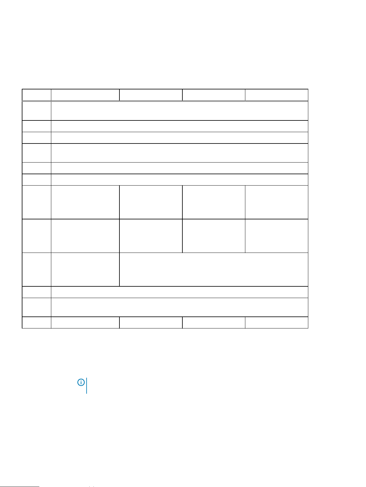
DD3300
DD3300 system features
Table 1 DD3300 system features
Feature 4 TB configuration 8 TB configuration 16 TB configuration 32 TB configuration
Rack
2U, supported in four-post racks only
Height
Power 1 or 2 hot-swappable power units
Fans 6 hot swappable fans, installed in two fan assemblies (3 fans per fan assembly)
Rack
Rack mount kit included with each system. Adjustable between 24 - 36 in. (60.9–76.2 cm).
mounting
Processor 1 x 8-core Intel 4110 series, hyperthreaded
Voltage 100–240 V~. Frequency: 50 Hz to 60 Hz.
Internal
4 x 4 TB HDD 10 x 4 TB HDD 10 x 4 TB HDD 12 x 4 TB HDD
3.5"
drives
(front)
Internal
N/A N/A N/A 4 x 4 TB HDD
3.5"
drives
(middle)
Internal
N/A 1 x 480 GB SSD for NVRAM
a
3.5"
drives
(rear)
NIC 4 x 1 GbE or 4 x 10 GbE (always present)b + 2 x 10 GbE (optional)
FC (DD
4 x 16 Gbps (optional)
VTL only)
Memory 16 GB or 24 GB
a.
The SSD is for use as an NVRAM device, and for SSD Cache Tier storage only. The maximum supported SSD Cache
Tier capacity is one percent of the Active Tier capacity. Other SSD-based functions such as Random I/O handling
are not supported for use with the SSD.
b.
Starting with DD OS 6.2, DD3300 systems ship with a 4 x 10 GbE RJ-45 network daughter card.
c.
24 GB of memory is required to use the FC module for DD VTL.
d.
A 16 TB system will have 56 GB of memory if it was a 4 TB system equipped with the FC module, and was later
upgraded to 16 TB.
c
48 GB 48 GB or 56 GB
Note: DD OS may report less storage and memory than indicated in this table. The unreported
resources are used for internal system processes.
20 Dell EMC DD and PowerProtect Hardware Features and Specifications
d
64 GB
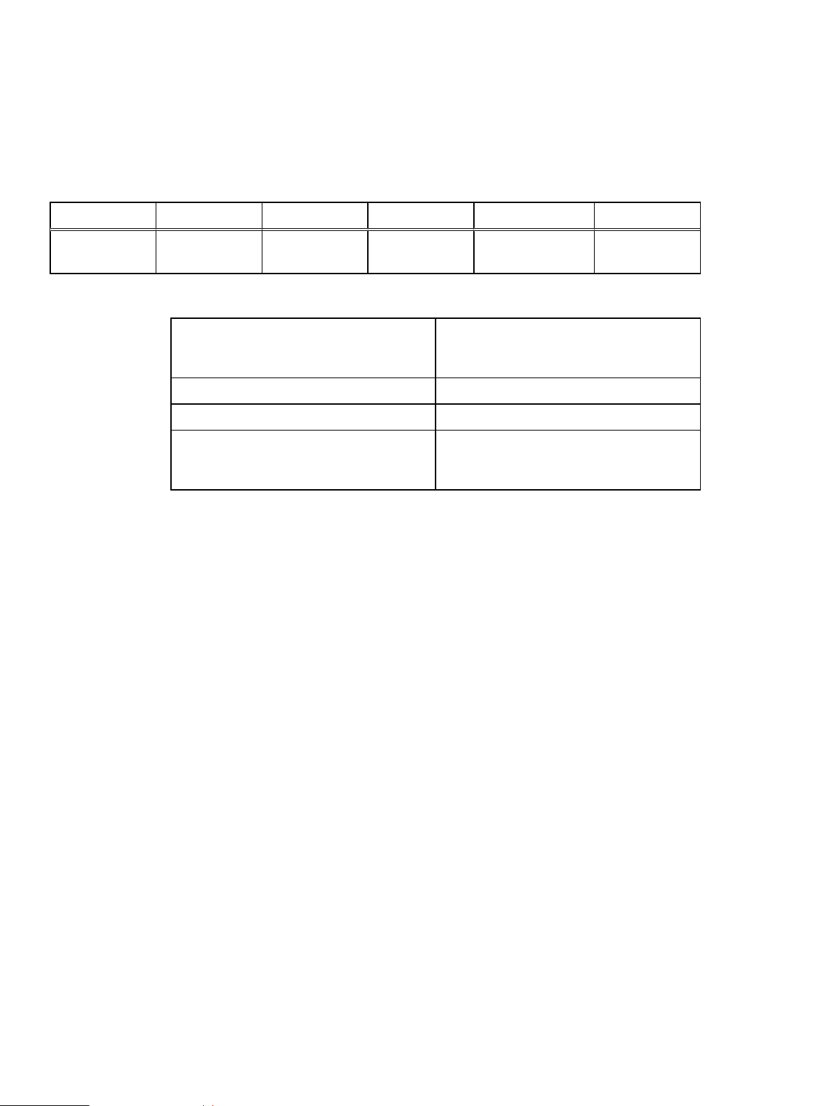
DD3300 system specifications
Table 2 DD3300 system specifications
Watts BTU/hr Weight Width Depth Height
750 2891 72.91 lb/33.1 kg 17.09 in/43.4 cm 28.17 inches/71.55cm3.42 in/8.68 cm
Table 3 System operating environment
Operating Temperature 50° to 95° F (10° to 35° C), derate 1.1° C
per 1000 feet, above 7500 feet up to 10,000
feet
Operating Humidity 20% to 80%, non-condensing
Non-operating Temperature -40° to +149° F (-40° to +65° C)
Operating Acoustic Noise Sound power, LWAd: 7.52 bels. Sound
pressure, LpAm: 56.4 dB. (Declared noise
emission per ISO 9296.)
DD3300
Dell EMC DD and PowerProtect Hardware Features and Specifications 21

DD3300
DD3300 storage capacity
The table lists the capacities of the systems. The system internal indexes and other product
components use variable amounts of storage, depending on the type of data and the sizes of files.
If you send different datasets to otherwise identical systems, one system may, over time, have
room for more or less actual backup data than another.
Table 4 DD3300 storage capacity
ConfigurationInternal
disks physical
4 TB
capacity /16
GB memory
8 TB
capacity/48
GB memory
16 TB
capacity/48
GB memory
32 TB
capacity/64
GB memory
4 x 4 TB
7200 RPM
NLSAS
10 x 4 TB
7200 RPM
NLSAS
10 x 4 TB
7200 RPM
NLSAS
l
12 x 4 TB
7200
RPM
NLSAS
(front)
l
4 x 4 TB
7200
RPM
NLSAS
(middle)
Internal disks virtual
ab
l
l
l
l
l
l
l
l
1 x 4 TB for
Active Tier
1 x 1 TB for
DD Cloud Tier
metadata
4 x 4 TB for
Active Tier
2 x 1 TB for
DD Cloud Tier
metadata
4 x 4 TB for
Active Tier
2 x 1 TB for
DD Cloud Tier
metadata
8 x 4 TB for
Active Tier
4 x 1 TB for
DD Cloud Tier
metadata
Raw storage Usable
storage
(local)
c
Cloud storage SSD metadata
cache storage
16 TB 4 TB 8 TB N/A
40 TB 8 TB 16 TB 160 GB
40 TB 16 TB 32 TB 160 GB
64 TB 32 TB 64 TB 320 GB
a.
The internal hard drives are configured in a RAID6 configuration. RAID6 provides the system with the ability to
withstand the simultaneous failure of two hard drives, or the failure of one hard drive while another hard drive is still
rebuilding after a drive replacement operation.
b.
After replacing a disk, it takes approximately 18 hours to complete the rebuild operation on the new disk, but may
take longer depending on the amount of activity on the system.
c.
The system compensates for the required file system overhead, so the reported usable capacity matches the
specified usable capacity.
22 Dell EMC DD and PowerProtect Hardware Features and Specifications
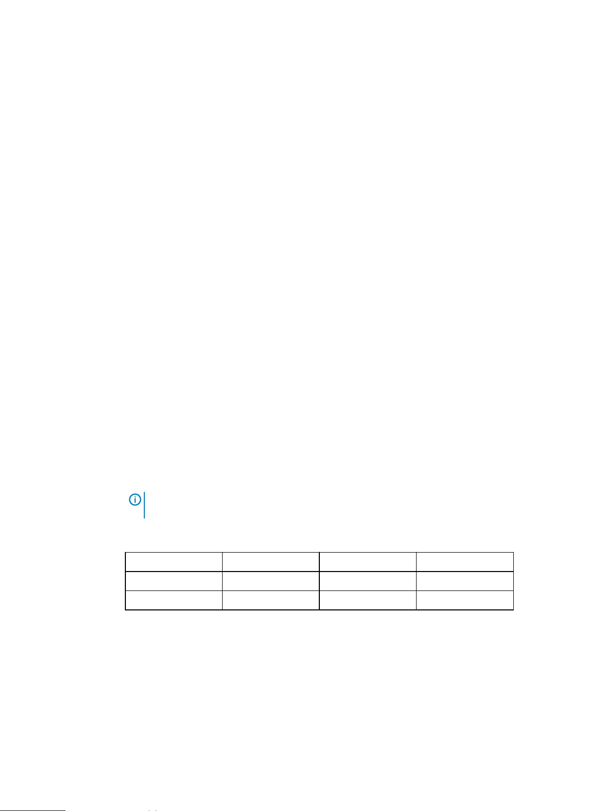
Front panel
DD3300
The DD3300 front panel consists of two control panels, which contain system LEDs and ports,
twelve 3.5" disk drive bays, and the service tag. Figure 1 on page 23 shows the locations of the
front panel components.
Figure 1 Front panel
1. Left control panel
2. 3.5" disk drive
3. Right control panel
4. Service tag.
Disk layout
The following table shows the physical location of each disk slot.
Table 5 Front disk slot numbers
Slot 0 (SW slot 1) Slot 3 (SW slot 4) Slot 6 (SW slot 7) Slot 9 (SW slot 10)
Slot 1 (SW slot 2) Slot 4 (SW slot 5) Slot 7 (SW slot 8) Slot 10 (SW slot 11)
Slot 2 (SW slot 3) Slot 5 (SW slot 6) Slot 8 (SW slot 9) Slot 11 (SW slot 12)
Left control panel
The left control panel contains system status LEDs. Figure 2 on page 24 shows the panel.
Note: Although the physical slots are numbered starting from 0, the software identifies the
slots starting at 1.
Dell EMC DD and PowerProtect Hardware Features and Specifications 23

DD3300
Figure 2 Left control panel
1. System status LEDs
2. System health and system ID indicator
3. iDRAC Quick Sync 2 wireless indicator (Not supported)
The system status LEDs turn solid amber if the system experiences an error in any of the following
categories. Under normal operating conditions, the system status LEDs remain off. From top to
bottom, the five system status LEDs are:
l
Drive indicator
l
Temperature indicator
24 Dell EMC DD and PowerProtect Hardware Features and Specifications

l
Electrical indicator
l
Memory indicator
l
PCIe indicator
The system health and system ID indicator has the following states:
l
Solid blue: Indicator is in system health mode. System is on and healthy.
l
Blinking blue: Indicator is in system ID mode.
l
Solid amber: System is in fail-safe mode.
l
Blinking amber: System is experiencing a fault.
Right control panel
The right control panel contains the system power button, and system maintenance ports. Figure 3
on page 26 shows the panel.
DD3300
Note: Press the System Health and System ID button to switch the indicator between
system health and system ID modes.
Dell EMC DD and PowerProtect Hardware Features and Specifications 25

DD3300
Figure 3 Right control panel
1. Power button
2. Not Supported -- 2 x USB 2.0 ports (Not supported)
3. Not Supported -- iDRAC Direct port (micro USB 2.0)
4. iDRAC Direct LED
5. Not Used -- VGA port
DD3300 supports the use of the iDRAC Direct port for console access. The iDRAC Direct LED
lights up when the iDRAC Direct port is connected. The LED has the following the states:
l
Solid green for two seconds: Service laptop is connected.
l
Flashing green: Connected laptop is recognized.
l
Off: Nothing is connected to the iDRAC Direct port.
26 Dell EMC DD and PowerProtect Hardware Features and Specifications

Front disks
DD3300
The DD3300 system contains 4, 10, or 12 front-mounted 3.5" HDDs, depending on the capacity
configuration. Each HDD has an activity indicator, and a status indicator. Figure 4 on page 27
shows the HDD indicators.
Figure 4 Disk LEDs
1. HDD activity indicator
2. HDD status indicator
Service tag
The HDD activity indicator blinks during drive activity.
The HDD status indicator has the following states:
l
Flashes green twice per second: Identifying drive or preparing for removal.
l
Off: Drive is ready for removal.
l
Flashes green, then amber, then turns off: Predicted drive failure.
l
Flashes amber four times per second: Drive failed.
l
Solid green: Drive online.
l
Flashes green slowly: Drive rebuilding.
l
Flashes green for three seconds, then amber for three seconds, then turns off: Rebuild
stopped.
The DD3300 system service tag is located at the front of the system, in the lower right-hand
corner of the chassis. This tag is on all DD3300 systems, and includes the product serial number.
Dell EMC DD and PowerProtect Hardware Features and Specifications 27

DD3300
Figure 5 Service tag
1. Information tag (top view)
2. Information tag (back view)
3. OpenManage Mobile (OMM) label
4. iDRAC MAC address and secure password label
5. Service tag
Rear panel
The DD3300 rear panel contains the system serial port, NIC cards, power supplies, and 3.5" drive
bays. shows the rear of the system.
Figure 6 Rear panel
1. Full height PCIe expansion card slots
l
The top slot is for the optional 2 x 10 GbE NIC
l
The middle slot is for the optional 4 x 16 Gbps FC module
l
The bottom slot is not supported
2.
Not Supported -- Half height PCIe expansion card slot
28 Dell EMC DD and PowerProtect Hardware Features and Specifications
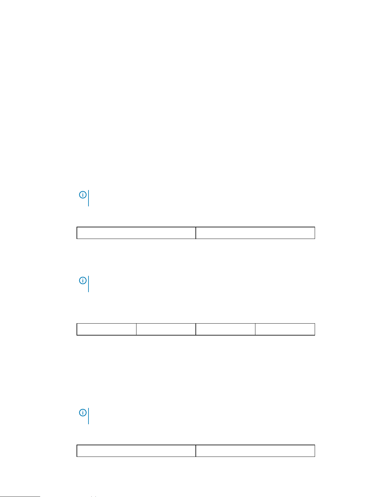
DD3300
3. Rear handle
4. 3.5" drive bays (used for 1 x 480 GB SSD in the 8 TB, 16 TB, and 32 TB configurations)
5. Power supply units (1 or 2)
6. Network daughter card Ethernet ports
7. Not Supported -- USB 3.0 ports
8. Not Supported -- VGA port
9. Serial port
10. iDRAC9 dedicated management port
11. System identification button
The DD3300 system supports the use of the iDRAC9 dedicated management port to emulate a
serial console.
Disk layout
8 TB, 16 TB, and 32 TB configurations use one rear slot for an SSD. 4 TB configurations do not use
an SSD. The following table shows the physical location of the rear SSD slots.
Note: Although the physical slots are numbered starting from 0, the software identifies the
slots starting at 1.
Table 6 Rear disk slot numbers
Slot 12 (SW slot 13) Slot 13 (SW slot 14)
Network port layout
The DD3300 network daughter card provides 4 x 1 GbE or 4 x 10 GbE network ports for network
connectivity.
Note: Starting with DD OS 6.2, DD3300 systems ship with a 4 x 10 GbE RJ-45 network
daughter card.
The following table lists the layout of the network daughter card ports.
Table 7 Network daughter card port identifiers
ethMa ethMb ethMc ethMd
An optional 2 x 10 GbE module is supported on the DD3300 system.
Figure 7 2 x 10 GbE module
The following table lists the layout of the 10 GbE ports.
Note: The 10 GbE module is inserted upside down, therefore the ports are in descending order
from left to right.
Table 8 Optional 10 GbE module port identifiers
eth1b eth1a
Dell EMC DD and PowerProtect Hardware Features and Specifications 29
DD3300
FC port layout
An optional 4 x 16 Gbps FC module is supported on the DD3300 system.
Figure 8 4 x 16 Gbps FC module
The following table lists the layout of the FC ports.
Table 9 Optional 16 Gbps FC module port identifiers
22a 22b 22c 22d
Product serial number tag (PSNT)
Some DD3300 systems have a PSNT tag located on the rear of the system, attached to the arm in
the center of the chassis. If this tag is not present, the product serial number is available from the
service tag located on the front of the system.
Rear SSD
Note: Service tag on page 27 describes the front-mounted service tag.
Figure 9 PSNT location
If present, the PSNT is identified by the part number (PN) 900-555-024. The 14 digit
alphanumeric string starting with "APM000" that accompanies the part number is the system
serial number. This serial number is the default system password for serial console and system
manager access.
The DD3300 8 TB, 16 TB, and 32 TB configurations use one rear-mounted 480 GB 2.5" SSD. The
SSD has an activity indicator, and a status indicator.
30 Dell EMC DD and PowerProtect Hardware Features and Specifications

Figure 10 Disk LEDs
1. HDD activity indicator
2. HDD status indicator
The HDD activity indicator blinks during drive activity.
The HDD status indicator has the following states:
l
Flashes green twice per second: Identifying drive or preparing for removal.
l
Off: Drive is ready for removal.
l
Flashes green, then amber, then turns off: Predicted drive failure.
l
Flashes amber four times per second: Drive failed.
l
Solid green: Drive online.
DD3300
NIC indicators
All network ports on the DD3300 system have link and activity LED indicators.
Figure 11 NIC LEDs
1. Link LED indicator
2. Activity LED indicator
The NIC LEDs have the following states:
Table 10 NIC LED states
Link indicator state Activity indicator state Meaning
Green Blinking green The NIC is connected to a
valid network at its maximum
Dell EMC DD and PowerProtect Hardware Features and Specifications 31

DD3300
Table 10 NIC LED states (continued)
Link indicator state Activity indicator state Meaning
port speed and data is being
sent or received.
Amber Blinking green The NIC is connected to a
valid network at less than its
maximum port speed and data
is being sent or received.
Green Off The NIC is connected to a
valid network at its maximum
port speed and data is not
being sent or received.
Amber Off The NIC is connected to a
valid network at less than its
maximum port speed and data
is not being sent or received.
Blinking green Off NIC identify is enabled
through the NIC configuration
utility.
Power supply indicators
The power supply unit has an illuminated, translucent handle that functions as a status LED.
Figure 12 Power supply LED
The indicator has the following states:
l
Green: Valid power source is connected, and the PSU is operational.
l
Blinking amber: Indicates a problem with the PSU.
l
Off: Power is not connected.
l
Blinking green: Firmware update is in progress.
CAUTION Do not disconnect the power cord or unplug the PSU when updating firmware. If
firmware update is interrupted, the PSUs do not function.
32 Dell EMC DD and PowerProtect Hardware Features and Specifications

Rear panel
DD3300
l
Blinking green, then off: When hot-plugging a PSU, the PSU handle blinks green five times at a
rate of 4 Hz and turns off. This indicates a PSU mismatch with respect to efficiency, feature
set, health status, or supported voltage.
The DD3300 rear panel contains the system serial port, NIC cards, power supplies, and 3.5" drive
bays. shows the rear of the system.
Figure 13 Rear panel
1. Full height PCIe expansion card slots
l
The top slot is for the optional 2 x 10 GbE NIC
l
The middle slot is for the optional 4 x 16 Gbps FC module
l
The bottom slot is not supported
2.
Not Supported -- Half height PCIe expansion card slot
3. Rear handle
4. 3.5" drive bays (used for 1 x 480 GB SSD in the 8 TB, 16 TB, and 32 TB configurations)
5. Power supply units (1 or 2)
6. Network daughter card Ethernet ports
7. Not Supported -- USB 3.0 ports
8. Not Supported -- VGA port
9. Serial port
10. iDRAC9 dedicated management port
11. System identification button
The DD3300 system supports the use of the iDRAC9 dedicated management port to emulate a
serial console.
Disk layout
8 TB, 16 TB, and 32 TB configurations use one rear slot for an SSD. 4 TB configurations do not use
an SSD. The following table shows the physical location of the rear SSD slots.
Dell EMC DD and PowerProtect Hardware Features and Specifications 33

DD3300
Note: Although the physical slots are numbered starting from 0, the software identifies the
slots starting at 1.
Table 11 Rear disk slot numbers
Slot 12 (SW slot 13) Slot 13 (SW slot 14)
Network port layout
The DD3300 network daughter card provides 4 x 1 GbE or 4 x 10 GbE network ports for network
connectivity.
Note: Starting with DD OS 6.2, DD3300 systems ship with a 4 x 10 GbE RJ-45 network
daughter card.
The following table lists the layout of the network daughter card ports.
Table 12 Network daughter card port identifiers
ethMa ethMb ethMc ethMd
An optional 2 x 10 GbE module is supported on the DD3300 system.
Figure 14 2 x 10 GbE module
The following table lists the layout of the 10 GbE ports.
Note: The 10 GbE module is inserted upside down, therefore the ports are in descending order
from left to right.
Table 13 Optional 10 GbE module port identifiers
eth1b eth1a
FC port layout
An optional 4 x 16 Gbps FC module is supported on the DD3300 system.
Figure 15 4 x 16 Gbps FC module
The following table lists the layout of the FC ports.
Table 14 Optional 16 Gbps FC module port identifiers
22a 22b 22c 22d
34 Dell EMC DD and PowerProtect Hardware Features and Specifications

Product serial number tag (PSNT)
Some DD3300 systems have a PSNT tag located on the rear of the system, attached to the arm in
the center of the chassis. If this tag is not present, the product serial number is available from the
service tag located on the front of the system.
Note: Service tag on page 27 describes the front-mounted service tag.
Figure 16 PSNT location
If present, the PSNT is identified by the part number (PN) 900-555-024. The 14 digit
alphanumeric string starting with "APM000" that accompanies the part number is the system
serial number. This serial number is the default system password for serial console and system
manager access.
DD3300
Rear SSD
The DD3300 8 TB, 16 TB, and 32 TB configurations use one rear-mounted 480 GB 2.5" SSD. The
SSD has an activity indicator, and a status indicator.
Figure 17 Disk LEDs
1. HDD activity indicator
2. HDD status indicator
The HDD activity indicator blinks during drive activity.
The HDD status indicator has the following states:
l
Flashes green twice per second: Identifying drive or preparing for removal.
l
Off: Drive is ready for removal.
l
Flashes green, then amber, then turns off: Predicted drive failure.
l
Flashes amber four times per second: Drive failed.
Dell EMC DD and PowerProtect Hardware Features and Specifications 35

DD3300
NIC indicators
l
Solid green: Drive online.
All network ports on the DD3300 system have link and activity LED indicators.
Figure 18 NIC LEDs
1. Link LED indicator
2. Activity LED indicator
The NIC LEDs have the following states:
Table 15 NIC LED states
Link indicator state Activity indicator state Meaning
Green Blinking green The NIC is connected to a
valid network at its maximum
port speed and data is being
sent or received.
Amber Blinking green The NIC is connected to a
valid network at less than its
maximum port speed and data
is being sent or received.
Green Off The NIC is connected to a
valid network at its maximum
port speed and data is not
being sent or received.
Amber Off The NIC is connected to a
valid network at less than its
maximum port speed and data
is not being sent or received.
Blinking green Off NIC identify is enabled
through the NIC configuration
utility.
Power supply indicators
The power supply unit has an illuminated, translucent handle that functions as a status LED.
36 Dell EMC DD and PowerProtect Hardware Features and Specifications

Figure 19 Power supply LED
The indicator has the following states:
l
Green: Valid power source is connected, and the PSU is operational.
l
Blinking amber: Indicates a problem with the PSU.
l
Off: Power is not connected.
l
Blinking green: Firmware update is in progress.
CAUTION Do not disconnect the power cord or unplug the PSU when updating firmware. If
firmware update is interrupted, the PSUs do not function.
l
Blinking green, then off: When hot-plugging a PSU, the PSU handle blinks green five times at a
rate of 4 Hz and turns off. This indicates a PSU mismatch with respect to efficiency, feature
set, health status, or supported voltage.
DD3300
Dell EMC DD and PowerProtect Hardware Features and Specifications 37

DD3300
38 Dell EMC DD and PowerProtect Hardware Features and Specifications

CHAPTER 2
DD4200
This chapter contains the following topics:
l
DD4200 system features.......................................................................................................40
l
DD4200 system specifications............................................................................................... 41
l
DD4200 storage capacity...................................................................................................... 42
l
Front Panel............................................................................................................................43
l
Back Panel.............................................................................................................................47
l
I/O modules and slot assignments.........................................................................................49
l
Internal system components.................................................................................................. 51
l
DD4200 and ES30 shelf guidelines.........................................................................................51
l
DD4200 and DS60 shelf guidelines........................................................................................68
Dell EMC DD and PowerProtect Hardware Features and Specifications 39

DD4200
DD4200 system features
The table summarizes the DD4200 system features.
Table 16 DD4200 system features
Feature DD4200 (Base configuration)
Rack height 4U, supported in four-post
racks only
Rack mounting Rack mount kit included with
each system. Adjustable
between 24 - 36 in. (60.9 - 76.2
cm).
Power 1 +1 redundant, hot-swappable
power units
Processor Two 8-core processors
NVRAM One 4-GB NVRAM module (and
companion BBU) for data
integrity during a power outage
Fans Hot-swappable, redundant, 5
Memory 16 x 8 GB DIMM (128 GB)
Internal drives SSD drives, 3 x 200 GB (base
10)
I/O module slots Nine replaceable I/O module
(Fibre Channel, Ethernet, and
SAS) slots, one BBU, one
NVRAM, and one Management
module slot. See Management
module and interfaces on page
47 and I/O modules and slot
assignments on page 49.
Supported capacity Non-extended retention 8 x 2-TB or 5 x 3-TB shelves
adding up to 189 TB of usable
external capacity.
DD Cloud Tier 189 TB of Active Tier capacity,
and 378 TB of Cloud Tier
capacity. 2x3 TB shelves are
required to store DD Cloud Tier
metadata.
DD Extended Retention 24 x 2-TB or 16 x 3-TB shelves
adding up to 378 TB of usable
external capacity. If lowercapacity 1 TB-drive-based
shelves are used, the maximum
configuration will also be limited
40 Dell EMC DD and PowerProtect Hardware Features and Specifications

Table 16 DD4200 system features (continued)
Feature DD4200 (Base configuration)
by a maximum shelf count of
32.
DD4200 system specifications
Table 17 DD4200 system specifications
Model Watts BTU/hr Power Weight Width Depth Height
DD4200
DD4200 800 2730 800 80 lb / 36.3kg17.5 in (44.5
cm)
Table 18 System operating environment
Operating Temperature 50° to 95° F (10° to 35° C), derate 1.1° C
per 1000 feet, above 7500 feet up to 10,000
feet
Operating Humidity 20% to 80%, non-condensing
Non-operating Temperature -40° to +149° F (-40° to +65° C)
Operating Acoustic Noise Sound power, LWAd: 7.52 bels. Sound
pressure, LpAm: 56.4 dB. (Declared noise
emission per ISO 9296.)
33 in (84
cm)
7 in (17.8
cm)
Dell EMC DD and PowerProtect Hardware Features and Specifications 41

DD4200
DD4200 storage capacity
Data Domain system internal indexes and other product components use variable amounts of
storage, depending on the type of data and the sizes of files. If you send different data sets to
otherwise identical systems, one system may, over time, have room for more or less actual backup
data than another.
Table 19 DD4200 storage capacity
System/ Installed
Memory
DD4200
(2 SAS I/O
Internal Disks
(SATA SSDs)
2.5 in. 3 @ 200 GB
No User Data
Data Storage
External Storage
Space
189 TB Up to a maximum of 8 x 2-TB
or 5 x 3-TB shelves.
3
modules)
128 GB
DD4200 with DD
Cloud Tier
1
(3 SAS I/O
modules)
2.5 in. 3 @ 200 GB
No User Data
l
189 TB (Active
Tier)
l
72 TB (DD
Up to a maximum of 8 x 2-TB
or 5 x 3-TB shelves.
2x3-TB shelves for DD Cloud
Tier metadata.
Cloud Tier
128 GB
metadata)
l
378 TB (DD
Cloud Tier)
DD4200 with
Extended
2.5 in. 3 @ 200 GB
No User Data
378 TB Up to a maximum of 16 x 2-TB
and 10 x 3-TB shelves.
Retention
software1 (4 SAS
I/O modules)
128 GB
1. Data Domain DD4200 controller with DD Extended Retention software.
2. Data Domain DD4200 controller with DD Cloud Tier.
3. The capacity will differ depending on the size of the external storage shelves used. This data based on ES30 shelves.
42 Dell EMC DD and PowerProtect Hardware Features and Specifications

Front Panel
DD4200
The photo shows the hardware features and interfaces on the front of the system.
Figure 20 Front panel components
(1) Filler panel
(2) The red box indicates the system processor (SP) module
(3) SSD drive #1
(4) Fan #0
(5) Power supply #B
(6) AC power disconnect plug
(7) AC power extender module
Power supply units
A system has two power supply units, numbered A and B from the bottom up. Each power supply
has its own integral cooling fan. Each power unit has three LEDs (see Figure 22 on page 45) that
indicates the following states:
l
AC LED: Glows green when AC input is good
l
DC LED: Glows green when DC output is good
l
Symbol “!”: Glows solid or blinking amber for fault or attention
The AC power plugs are located to the right of each power supply. These plugs are pulled to
disconnect AC power to each power supply.
AC power extender module
AC power entry is connected at the rear of the system. The AC power extender module provides
power to the two power supplies on the front of the system. AC Power plugs are located in the
front. The module is adjacent to the SP module and can be removed and replaced.
Dell EMC DD and PowerProtect Hardware Features and Specifications 43

DD4200
Cooling Fans
A system contains five hot-swappable cooling fans in a 4+1 redundant configuration. The fans
provide cooling for the processors, DIMMs, IO modules, and the management module. Each fan
has a fault LED which causes the fan housing to glow amber. A system can run with one fan
faulted or removed.
Solid-state drives
A system contains three hot-swappable 2.5" solid-state drive (SSD) bays that are located in the
front and on top of the fan modules. There are four drive bays, with the left-most bay containing a
blank. The next drive to the right of the blank is SSD #1, the next is #2, and the right-most bay
contains SSD #3. No user backup data is kept on the SSDs.
Each drive has a blue colored power LED and an amber fault LED.
Front LED Indicators
The photo below indicates the location of the four system LEDs.
Figure 21 System LEDs
The next photo shows the location of the system LED legend label. Figure 23 on page 45 shows
the power supply LEDs. Other front LEDs are shown in Figure 24 on page 46. LED states are
described in Table 20 on page 46.
44 Dell EMC DD and PowerProtect Hardware Features and Specifications

Figure 22 System LED legend label
DD4200
The power supply LEDs include:
l
AC LED on top
l
DC LED in the middle
l
Failure LED on the bottom
Figure 23 Power supply LEDs
Each SSD has two LEDs as shown in the following figure. The lower left corner of the housing
around each fan acts as an LED, glowing amber when the fan has failed.
Dell EMC DD and PowerProtect Hardware Features and Specifications 45

DD4200
Figure 24 Fan and SSD LEDs
Table 20 LED status indicators
Part Description or Location State
System Dot within a circle (top LED) Blue indicates power on and
normal operation.
System, SP fault Exclamation point within a
triangle
Dark indicates normal
operation. Amber indicates
failure.
System, chassis fault Exclamation point within a
triangle with a light below
Dark indicates normal
operation. Yellow indicates a
fault condition.
System Marked out hand within a
black square (bottom LED)
White warms not to remove
the unit.
Power supply AC LED Steady green indicates normal
AC power.
Power supply DC LED Steady green indicates normal
DC power.
Power supply Failure LED Solid amber indicates a failed
power supply.
SSD Top LED Solid blue, disk ready, blinks
while busy.
SSD Bottom LED Dark indicates healthy. Solid
Fan Fan housing The fan housing glows an
46 Dell EMC DD and PowerProtect Hardware Features and Specifications
amber indicates disk fail.
amber color during fan failure.

Back Panel
DD4200
The photo shows the hardware features and interfaces on the back of the system.
Figure 25 Features on rear of chassis
1. Upper level contains all blanks
2. AC power extender module
3. Management module (slot Mgmt A)
4. Red box indicating I/O modules (slots 0-8)
5. Battery backup (BBU in slot 9)
6. NVRAM module (slot 10)
7. Cage covering the BBU and NVRAM combination module
8. I/O LED at the end of each I/O module handle
9. Location of serial number label/tag
Note: For modules containing multiple ports, the bottom port is numbered as zero (0) with
numbers increasing going upward.
I/O module LEDs
Each I/O module ejector handle contains a bi-colored LED. Green indicates normal function, while
an amber color indicates a fault condition.
Management module and interfaces
The management module is on the left-most side when facing the back of the system, in slot
Mgmt A. The process to remove and add a management module is the same as the I/O modules,
however, the management module can only be accommodated in Mgmt A slot.
The management module contains one external LAN connection for management access to the SP
module. One micro DB-9 connector is included to provide the console. A USB port is provided for
use during service of the system to allow booting from a USB flash device.
Dell EMC DD and PowerProtect Hardware Features and Specifications 47

DD4200
Figure 26 Interfaces on the management module
l
1 - Ethernet port
l
2 - USB port
l
3 - Micro serial port
48 Dell EMC DD and PowerProtect Hardware Features and Specifications

I/O modules and slot assignments
The table shows the I/O module slot assignments for the systems. See Figure 25 on page 47 for a
view of the slot positions on the back panel and Figure 27 on page 51 for a top view.
Table 21 DD4200 slot assignments
DD4200
Slot Number DD4200 DD4200 with Extended
Retention Software
MGMT A Management module Management module Management module
0 Fibre Channel (FC), Ethernet or
empty
1 FC, Ethernet or empty FC, Ethernet or empty FC, Ethernet or empty
2 FC, Ethernet or empty FC, Ethernet or empty FC, Ethernet or empty
3 FC, Ethernet or empty FC, Ethernet or empty FC, Ethernet or empty
4 Ethernet or empty Ethernet or empty Ethernet or empty
5 Ethernet or empty SAS Ethernet or empty
6 Empty SAS SAS
7 SAS SAS SAS
8 SAS SAS SAS
9 BBU BBU BBU
10 NVRAM NVRAM NVRAM
FC, Ethernet or empty FC, Ethernet or empty
DD4200 with DD Cloud
Tier
Slot addition rules
l
A maximum of six optional I/O modules (FC plus Ethernet) are allowed in systems without
Extended Retention software, and a maximum of five optional I/O modules (FC plus Ethernet)
are allowed in systems with Extended Retention software.
l
Additional FC modules should be installed in numerically increasing slot numbers immediately to
the right of the existing FC modules, or starting in slot 0 if no FC modules were originally
installed. A maximum of four FC modules are allowed in a system.
l
Additional Ethernet modules should be installed in numerically decreasing slot numbers
immediately to the left of the existing Ethernet modules or starting in slot 4 if no Ethernet
modules were originally installed. For systems without Extended Retention software, a
maximum of six (limited to four of any one type) Ethernet modules can be present. For
systems with Extended Retention software, a maximum of five (limited to four of any one
type) Ethernet modules can be present.
l
All systems include two SAS modules in slots 7 and 8. Systems with Extended Retention
software must have two additional SAS modules in slots 5 and 6.
l
For systems without Extended Retention software, if adding I/O modules results in the allowed
maximum of six I/O modules present, slot 5 is used. Slot 5 is only used for an Ethernet module.
Adding FC modules in this specific case require moving an existing Ethernet module to slot 5.
Other than this specific case, it is not recommended to move I/O modules between slots.
Dell EMC DD and PowerProtect Hardware Features and Specifications 49

DD4200
l
Adding Extended Retention software to a system includes adding two SAS modules in slots 5
and 6. If the system originally had the maximum of 6 optional I/O modules, the I/O module in
slot 5 must be permanently removed from the system.
Fibre Channel (FC) I/O Module Option
An FC I/O module is a dual-port Fibre Channel module. The optional virtual tape library (VTL)
feature requires at least one FC I/O module. Boost over Fiber Channel is optional and the total FC
HBAs cannot exceed more than allowable Fibre Channel cards per controller.
Ethernet I/O Module Options
The available Ethernet I/O modules are:
l
Dual Port 10GBase-SR Optical with LC connectors
l
Dual Port 10GBase-CX1 Direct Attach Copper with SPF+ module
l
Quad Port 1000Base-T Copper with RJ-45 connectors
l
Quad port 2 port 1000Base-T Copper (RJ45) /2 port 1000Base-SR Optical
50 Dell EMC DD and PowerProtect Hardware Features and Specifications

Internal system components
The photo shows the system with the system processor (SP) module that is removed from the
chassis and the SP cover removed.
Figure 27 Top view of SP module with SP cover removed
DD4200
l
1 - Front of system
l
2 - Four groups of 4 DIMM cards
DIMM modules
DD4200 systems contain 16 x 8 GB of memory DIMM.
DD4200 and ES30 shelf guidelines
The Data Domain system rediscovers newly configured shelves after it restarts. You can power off
the system and recable shelves to any other position in a set, or to another set. To take advantage
of this flexibility, you need to follow these rules before making any cabling changes:
l
Do not exceed the maximum shelf configuration values for your Data Domain system as listed
in the following table below.
l
Use the Installation and Setup Guide for your Data Domain system to minimize the chance of a
cabling mistake.
l
A Data Domain system cannot exceed its maximum raw external shelf capacity, regardless of
added shelf capacity.
l
ES30 SATA shelves must be on their own chain.
Dell EMC DD and PowerProtect Hardware Features and Specifications 51

DD4200
Note:
l
ES30 SAS shelves must be running DD OS 5.4 or later.
l
ES30-45 SATA shelves must be running DD OS 5.4 or later.
l
DD OS 5.7 and later support 4TB drives.
Table 22 DD4200 and ES30 shelf configuration
DD system Memory
required
(GB)
DD4200
DD4200 ER
DD4200 w/ DD
3
128 2x4 SAS 30,
3, 4
128 4x4 SAS 30,
128 3x4 SAS 30,
Cloud Tier
1. This figure only counts drives that have user data in the shelves.
2. The raw capacity of an ES30 is 125% of the available capacity.
3. The maximum shelf count for any specific drive/shelf size might be less than the product of max shelves x max shelves per set.
4. With Extended Retention software.
5. ES30-45 (SATA) is only supported with DD OS 5.4 or later.
6. 5 shelves maximum with ES30, 4 is the recommended maximum.
SAS cards/
port per
card
ES30
support
(TB)
45; SATA
15, 30,
5
45
45; SATA
15, 30,
5
45
45; SATA
15, 30,
5
45
Max
shelves
per set
6
5
Max
number of
sets
Max external
capacity
available (TB)
1
Max RAW
external
capacity
(TB)
4 192 256
7 8 384 512
7 8 192 (max),
additional 72
SAS dedicated
to DD Cloud
Tier
256 (max),
additional 90
SAS
dedicated to
DD Cloud Tier
2
Types of cabinets and power connections
The ES30 chassis is installed in two types of racks: 40U-C (existing racks) and the 40U-P (newer
racks). The racks use one phase or 3-phase power connections.
This section describes the different types of racks and the power connections for the ES30
chassis.
Single phase power connections for 40U-P (current racks)
The following illustrations show single phase power connections for 40U-P racks that are used for
several Data Domain systems.
52 Dell EMC DD and PowerProtect Hardware Features and Specifications

Figure 28 Single phase power connections for the 40U-P expansion rack
DD4200
Dell EMC DD and PowerProtect Hardware Features and Specifications 53

DD4200
Figure 29 Single phase power connections for the DD4200, DD4500, and DD7200
Single phase power connections for 40U-C (older racks)
The following illustrations show single phase power connections for 40U-C racks that are used for
several Data Domain systems.
54 Dell EMC DD and PowerProtect Hardware Features and Specifications

Figure 30 Single phase power connections for the Expansion Rack
DD4200
Dell EMC DD and PowerProtect Hardware Features and Specifications 55

DD4200
Figure 31 Single phase power connections for the DD4200, DD4500, and DD7200
3-Phase power connections for 40U-C (older racks)
The following illustrations show single phase power connections for 40U-C racks that are used for
several Data Domain systems.
56 Dell EMC DD and PowerProtect Hardware Features and Specifications

Figure 32 Single phase power connections for the Expansion Rack
DD4200
Dell EMC DD and PowerProtect Hardware Features and Specifications 57

DD4200
Figure 33 Single phase power connections for the DD4200, DD4500, and DD7200
3-Phase power connections for 40U-P (current racks)
Some environments use 3-phase power for 40U-P racks that are used for several Data Domain
systems. In those situations, it is desirable to balance the current draw across all three phases. The
recommended 3-phase power cabling attempts to do that, but an optimal configuration depends
on the specific installation. The following illustrations show recommended 3-phase power
connections for several Data Domain systems.
Note: The next few diagrams show recommended 3-phase delta power connections.
58 Dell EMC DD and PowerProtect Hardware Features and Specifications

Figure 34 Recommended 3-phase delta power connections for the Expansion Rack
DD4200
Dell EMC DD and PowerProtect Hardware Features and Specifications 59

DD4200
Figure 35 Recommended 3-phase delta power connections for DD4200, DD4500, and DD7200
Note: The next few diagrams show recommended 3-phase wye power connections.
60 Dell EMC DD and PowerProtect Hardware Features and Specifications

Figure 36 Recommended 3-phase wye power connections for the Expansion Rack
DD4200
Dell EMC DD and PowerProtect Hardware Features and Specifications 61

DD4200
Figure 37 3-phase wye power connections for DD4200, DD4500, and DD7200
Cabling shelves
Note:
62 Dell EMC DD and PowerProtect Hardware Features and Specifications

l
Before cabling the shelves, physically install all shelves in the racks. Refer to the rail kit
installation instructions included with the ES30 shelf for rack mounting.
l
The documentation refers to two SAS HBAs. If only one HBA is allowed in a system, then
use another port as defined later for that specific system.
l
On an HA system, add cables from the second node to open ports at the end of the sets.
The ports on the second node must connect to the same sets as the corresponding ports
on the first node.
Ports on the system’s SAS HBA cards connect directly to a shelf controller’s host port. For
redundancy, you need to create dual paths by using a port on one SAS HBA card to connect to one
shelf controller in each shelf set, and a port on another SAS HBA card to connect to another shelf
controller in the same shelf set. With dual paths, if one SAS HBA card fails, the shelf is still
operational. However, in the unlikely event any single shelf becomes completely disconnected from
power or SAS cables and becomes disconnected from a previously operational shelf, the file
system goes down and the shelf is not operational. This is considered a double failure.
There are two kinds of configurations: one shelf in a set or multiple shelves in a set.
ES30 and DD4200 cabling
There are a few rules that must be followed when adding a mixture of ES20, ES30 SATA, and
ES30 SAS shelves to your system. If a system does not follow ALL of these rules it is not a
legitimate configuration.
Prerequisites:
l
Follow the minimum and maximum shelf capacity configuration provided in the table.
l
You cannot have ES20 and ES30 shelves in the same set.
l
You cannot have ES30 SATA and ES30 SAS shelves in the same set.
l
You cannot exceed the maximum amount of raw capacity displayed in the product's cabling
table.
l
The maximum number of shelves displayed in the product's cabling table cannot be exceeded.
l
You cannot have more than four ES20s in a single set (maximum preference is three).
l
You cannot have more than five ES30s in a single set (maximum preference is four).
l
You can have a maximum of seven ES30s for systems with Extended Retention software.
l
There are no specific placement or cabling requirements for the metadata shelves for DD Cloud
Tier configurations. These shelves can be installed and cabled the same way as standard ES30
shelves.
DD4200
Note: An ES20 requires more power than an ES30. Ensure that your rack is configured to
handle the power needs.
The tables below show how to configure a mixed system. To use the tables, go to the appropriate
system. Then find the number of ES20s that are to be configured in the first column. The next
column defines the number of ES20 sets. If there are multiple rows with the same number of
ES20s then pick the row with the appropriate number of ES20 SATA shelves. The next column in
that row defines the number of sets of ES30 SATA shelves. Finally, there may be entries for the
number of desired ES30 SAS shelves and the number of sets to be used.
If the combinations of shelves exceed the supported usable storage, there may not be an entry.
The entries are based on the smallest usable storage per shelf type (12TB for ES20, 12 TB for
ES30 SATA, and 24TB for ES30 SAS). Always check that the sum of the usable storage of all of
the shelves does not exceed the supported usable storage of the configuration.
Dell EMC DD and PowerProtect Hardware Features and Specifications 63

DD4200
Table 23 Minimum and maximum configurations
System Minimum
appliance shelf
count
4200
1 16
(192)
Maximum appliance
shelf count
DD Cloud Tier
systems in TB
l
189
l
90 for
metadata
Extended Retention
systems (ER) in TB
l
DD OS 5.4 and earlier:
576
l
DD OS 5.5 and later:
Max shelves
for ER
32
385
Systems without Extended Retention or DD Cloud Tier all support four chains. The following tables
show combinations of ES20 and ES30 shelves. For combinations of any two types of shelves,
these tables can be used as a guide.
Table 24 DD4200 cabling information
DD4200
ES20 ES20 chains ES30 SATA ES30 SATA
chains
13-16 4 0 0 0 0
9-12 3 1-5 1 0 0
9-12 3 0 0 1-3 1
5-8 2 6-10 2 0 0
ES30 SAS ES30 SAS
chains
5-8 2 1-5 1 1-5 1
5-8 2 0 0 5 2
5-8 2 0 0 1-4 1
1-4 1 8-12 3 0 0
1-4 1 6-10 2 1-5 1
1-4 1 1-5 1 1-4 1
1-4 1 1-5 1 5-7 2
1-4 1 0 0 1-4 1
1-4 1 0 0 5-7 2
0 0 13-16 4 0 0
0 0 9-12 3 1-3 1
0 0 5-8 2 1-4 1
0 0 5-8 2 5 2
0 0 1-4 1 1-4 1
0 0 1-4 1 5-7 2
0 0 0 0 1-4 1
0 0 0 0 5-8 2
64 Dell EMC DD and PowerProtect Hardware Features and Specifications

The following figures show cabling for base systems, systems with the Extended Retention
software option, and systems integrated with an Avamar system.
Figure 38 Recommended DD4200 cabling
DD4200
Dell EMC DD and PowerProtect Hardware Features and Specifications 65

DD4200
Figure 39 Recommended cabling for DD4200 integrated with Avamar
66 Dell EMC DD and PowerProtect Hardware Features and Specifications

DD4200
Figure 40 Recommended cabling for DD4200 system with extended retention software or DD Cloud Tier
Dell EMC DD and PowerProtect Hardware Features and Specifications 67

DD4200
Figure 41 Recommended cabling for DD4200 with extended retention and integrated with Avamar
DD4200 and DS60 shelf guidelines
The Data Domain system rediscovers newly configured shelves after it restarts. You can power off
the system and recable shelves to any other position in a set, or to another set. To take advantage
of this flexibility, you need to follow these rules before making any cabling changes:
l
Do not exceed the maximum shelf configuration values for your Data Domain system as listed
in the following table.
l
For redundancy, the two connections from a Data Domain system to a set of shelves must use
ports on different SAS I/O modules.
68 Dell EMC DD and PowerProtect Hardware Features and Specifications

l
Use the Installation and Setup Guide for your Data Domain system to minimize the chance of a
cabling mistake.
l
A Data Domain system cannot exceed its maximum raw external shelf capacity, regardless of
added shelf capacity.
l
ES30 SATA shelves must be on their own chain.
l
If ES30 SAS shelves are on the same chain as a DS60, the maximum number of shelves on that
chain is 5.
l
DD OS 5.7.1 does not support HA with SATA drives.
Table 25 DD4200 and DS60 shelf configuration
DD4200
DD system Memory
required
(GB)
SAS
cards/
port per
card
DS60 support
(TB)
Max
shelves
per set
Max
number of
sets
Max
external
capacity
available
1
(TB)
Max RAW
external
capacity
(TB)
DD4200 128 2x4 SAS 45 1 4 192 240
DD4200 ER
2
128 4x4 SAS 45 2 8 384 480
Note: An entry of 45 corresponds to DS60-3 models and an entry of 60 corresponds to
DS60-4 models.
1. This column only counts drives that have user data in the shelves. For example, a DS60 4-240 has 192TB.
2. With Extended Retention software.
Single phase power connections for 40U-P (current racks)
The following figures show single phase power connections for several Data Domain systems.
Dell EMC DD and PowerProtect Hardware Features and Specifications 69

DD4200
Figure 42 Single phase power connections for DD4200, DD4500, and DD7200 systems
70 Dell EMC DD and PowerProtect Hardware Features and Specifications

3-phase power connections for 40U-P (current racks)
Some environments use 3-phase power for 40U-P racks used for several Data Domain systems. In
those situations it is desirable to balance the current draw across all 3 phases. The recommended
3-phase power cabling attempts to do that, but an optimal configuration is dependent on the
specific installation. The following figures show recommended 3-phase power connections for
several Data Domain systems.
Note: The next few diagrams show recommended 3-phase delta power connections.
DD4200
Dell EMC DD and PowerProtect Hardware Features and Specifications 71

DD4200
Figure 43 3-phase delta power connections for DS60 expansion shelves (full-racked)
72 Dell EMC DD and PowerProtect Hardware Features and Specifications

Figure 44 3-phase delta power connections for DD4200, DD4500, and DD7200 systems
DD4200
Note: The next few diagrams show recommended 3-phase wye power connections.
Dell EMC DD and PowerProtect Hardware Features and Specifications 73

DD4200
Figure 45 3-phase wye power connections for DS60 expansion shelves (full-racked)
74 Dell EMC DD and PowerProtect Hardware Features and Specifications

Figure 46 3-phase wye power connections for DD4200, DD4500, and DD7200 systems
DD4200
Dell EMC DD and PowerProtect Hardware Features and Specifications 75

DD4200
DS60 and DD4200 cabling
There are a few rules that must be followed when adding a mixture of DS60 and other shelf types
to your system.
CAUTION If a system does not follow all these rules, it is not a legitimate configuration.
Prerequisites:
l
You cannot exceed the maximum amount of usable capacity displayed in cabling table for each
system.
l
You cannot exceed the maximum number of shelves displayed in cabling table for each system.
l
You cannot connect more than two DS60 shelves in a single set.
Table 26 Minimum and maximum configurations
System Appliance maximum Minimum appliance shelf count
DD4200 192 TB 1
Mixing DS60, ES30, and ES20 shelves:
The non-Extended Retention versions of these systems all support four chains.
Extra planning and reconfiguration may be required to add DS60 shelves to system with ES20
shelves, ES30 SATA shelves, or a combination of shelves.
l
The ES20 shelves must be on their own set. Minimize the ES20 set count by combining up to
four ES20s per set.
l
ES30 SATA shelves must also be on their own sets. Minimize the ES30 set count by combining
up to five ES30s per set. If required, combine up to seven ES30 SAS shelves per set to
minimize the set count.
l
A set can contain a maximum of two DS60 shelves and, if required because of other
restrictions, add ES30 SAS shelves up to a maximum of five shelves in that set.
Note: The configuration rules apply also to Extended Retention systems.
The following figures show cabling for base systems and systems with the Extended Retention
software.
Note: It is recommended that the DS60 shelf with the greater number of drives should always
be placed in the bottom position.
76 Dell EMC DD and PowerProtect Hardware Features and Specifications

Figure 47 Recommended cabling for DD4200 (3TB drives)
DD4200
Note: One DS60 shelf can have 60 drives and the second DS60 shelf can have 15
drives.
Dell EMC DD and PowerProtect Hardware Features and Specifications 77

DD4200
Figure 48 Recommended cabling for DD4200 (3TB drives) with Extended Retention Software
Note: With four shelves, two DS60 shelves can have 60 drives each and the other
DS60 shelves can only have 15 drives each. It is also possible to configure two full
DS60 shelves and one DS60 shelf with 30 drives.
78 Dell EMC DD and PowerProtect Hardware Features and Specifications

CHAPTER 3
DD4500
This chapter contains the following topics:
l
DD4500 system features.......................................................................................................80
l
DD4500 system specifications...............................................................................................81
l
DD4500 storage capacity......................................................................................................82
l
Front Panel............................................................................................................................83
l
Back Panel.............................................................................................................................87
l
I/O modules and slot assignments.........................................................................................89
l
Internal system components.................................................................................................. 91
l
DD4500 and ES30 shelf guidelines.........................................................................................91
l
DD4500 and DS60 shelf guidelines...................................................................................... 100
Dell EMC DD and PowerProtect Hardware Features and Specifications 79

DD4500
DD4500 system features
The table summarizes the DD4500 system features.
Table 27 DD4500 system features
Feature DD4500
Rack height 4U, supported in four-post
racks only
Rack mounting Rack mount kit included with
each system. Adjustable
between 24 - 36 in. (60.9 - 76.2
cm).
Power 1 +1 redundant, hot-swappable
power units
Processor Two 8-core processors
NVRAM One 4-GB NVRAM module (and
companion BBU) for data
integrity during a power outage
Fans Hot-swappable, redundant, 5
Memory 8 x 8 GB DIMM + 8 x 16 GB
DIMM (192 GB)
Internal drives SSD drives, 3 x 200 GB (base
10)
I/O module slots Nine replaceable I/O module
(Fibre Channel, Ethernet, and
SAS) slots, one BBU, one
NVRAM, and one Management
module slot. See Management
module and interfaces on page
47 and I/O modules and slot
assignments on page 49.
Supported capacity Non-extended retention 12 x 2-TB or 8 x 3-TB shelves
adding up to 285 TB of usable
external capacity.
DD Cloud Tier 285 TB of Active Tier capacity,
and 570 TB of Cloud Tier
capacity. 2 x 4 TB shelves are
required to store DD Cloud Tier
metadata.
DD Extended Retention 32 shelves adding up to 570 TB
80 Dell EMC DD and PowerProtect Hardware Features and Specifications
of usable external capacity. If
lower-capacity 1 TB-drivebased shelves are used, the
maximum configuration will also

Table 27 DD4500 system features (continued)
Feature DD4500
be limited by a maximum shelf
count of 40.
DD4500 system specifications
Table 28 DD4500 system specifications
Model Watts BTU/hr Power Weight Width Depth Height
DD4500
DD4500 800 2730 800 80 lb / 36.3kg17.5 in (44.5
cm)
Table 29 System operating environment
Operating Temperature 50° to 95° F (10° to 35° C), derate 1.1° C
per 1000 feet, above 7500 feet up to 10,000
feet
Operating Humidity 20% to 80%, non-condensing
Non-operating Temperature -40° to +149° F (-40° to +65° C)
Operating Acoustic Noise Sound power, LWAd: 7.52 bels. Sound
pressure, LpAm: 56.4 dB. (Declared noise
emission per ISO 9296.)
33 in (84
cm)
7 in (17.8
cm)
Dell EMC DD and PowerProtect Hardware Features and Specifications 81

DD4500
DD4500 storage capacity
The table lists the capacities of the systems. Data Domain system internal indexes and other
product components use variable amounts of storage, depending on the type of data and the sizes
of files. If you send different data sets to otherwise identical systems, one system may, over time,
have room for more or less actual backup data than another.
Table 30 DD4500 storage capacity
System/ Installed
Memory
DD4500
(2 SAS I/O
Internal Disks
(SATA SSDs)
2.5 in. 3 @ 200 GB
No User Data
Data Storage
External Storage
Space
285 TB Up to a maximum of 12 x 2-TB
or 8 x 3-TB shelves.
1
modules)
192 GB
DD4500 with DD
Cloud Tier
1
(3 SAS I/O
modules)
2.5 in. 3 @ 200 GB
No User Data
l
285 TB (Active
Tier)
l
96 TB (DD
Up to a maximum of 12 x 2-TB
or 8 x 3-TB shelves.
2x4-TB shelves for DD Cloud
Tier metadata.
Cloud Tier
192 GB
metadata)
l
570 TB (DD
Cloud Tier)
DD4500 with
Extended
2.5 in. 3 @ 200 GB
No User Data
570 TB Up to a maximum of 24 x 2-
TB or 16 x 3-TB shelves.
Retention
software1 (4 SAS
I/O modules)
192 GB
1
The capacity will differ depending on the size of the external storage shelves used. This data
based on ES30 shelves.
82 Dell EMC DD and PowerProtect Hardware Features and Specifications

Front Panel
DD4500
The photo shows the hardware features and interfaces on the front of the system.
Figure 49 Front panel components
(1) Filler panel
(2) The red box indicates the system processor (SP) module
(3) SSD drive #1
(4) Fan #0
(5) Power supply #B
(6) AC power disconnect plug
(7) AC power extender module
Power supply units
A system has two power supply units, numbered A and B from the bottom up. Each power supply
has its own integral cooling fan. Each power unit has three LEDs (see Figure 22 on page 45) that
indicates the following states:
l
AC LED: Glows green when AC input is good
l
DC LED: Glows green when DC output is good
l
Symbol “!”: Glows solid or blinking amber for fault or attention
The AC power plugs are located to the right of each power supply. These plugs are pulled to
disconnect AC power to each power supply.
AC power extender module
AC power entry is connected at the rear of the system. The AC power extender module provides
power to the two power supplies on the front of the system. AC Power plugs are located in the
front. The module is adjacent to the SP module and can be removed and replaced.
Dell EMC DD and PowerProtect Hardware Features and Specifications 83

DD4500
Cooling Fans
A system contains five hot-swappable cooling fans in a 4+1 redundant configuration. The fans
provide cooling for the processors, DIMMs, IO modules, and the management module. Each fan
has a fault LED which causes the fan housing to glow amber. A system can run with one fan
faulted or removed.
Solid-state drives
A system contains three hot-swappable 2.5" solid-state drive (SSD) bays that are located in the
front and on top of the fan modules. There are four drive bays, with the left-most bay containing a
blank. The next drive to the right of the blank is SSD #1, the next is #2, and the right-most bay
contains SSD #3. No user backup data is kept on the SSDs.
Each drive has a blue colored power LED and an amber fault LED.
Front LED Indicators
The photo below indicates the location of the four system LEDs.
Figure 50 System LEDs
The next photo shows the location of the system LED legend label. Figure 52 on page 85 shows
the power supply LEDs. Other front LEDs are shown in Figure 53 on page 86. LED states are
described in Table 31 on page 86.
84 Dell EMC DD and PowerProtect Hardware Features and Specifications

Figure 51 System LED legend label
DD4500
The power supply LEDs include:
l
AC LED on top
l
DC LED in the middle
l
Failure LED on the bottom
Figure 52 Power supply LEDs
Each SSD has two LEDs as shown in the following figure. The lower left corner of the housing
around each fan acts as an LED, glowing amber when the fan has failed.
Dell EMC DD and PowerProtect Hardware Features and Specifications 85

DD4500
Figure 53 Fan and SSD LEDs
Table 31 LED status indicators
Part Description or Location State
System Dot within a circle (top LED) Blue indicates power on and
normal operation.
System, SP fault Exclamation point within a
triangle
Dark indicates normal
operation. Amber indicates
failure.
System, chassis fault Exclamation point within a
triangle with a light below
Dark indicates normal
operation. Yellow indicates a
fault condition.
System Marked out hand within a
black square (bottom LED)
White warms not to remove
the unit.
Power supply AC LED Steady green indicates normal
AC power.
Power supply DC LED Steady green indicates normal
DC power.
Power supply Failure LED Solid amber indicates a failed
power supply.
SSD Top LED Solid blue, disk ready, blinks
while busy.
SSD Bottom LED Dark indicates healthy. Solid
Fan Fan housing The fan housing glows an
86 Dell EMC DD and PowerProtect Hardware Features and Specifications
amber indicates disk fail.
amber color during fan failure.

Back Panel
DD4500
The photo shows the hardware features and interfaces on the back of the system.
Figure 54 Features on rear of chassis
1. Upper level contains all blanks
2. AC power extender module
3. Management module (slot Mgmt A)
4. Red box indicating I/O modules (slots 0-8)
5. Battery backup (BBU in slot 9)
6. NVRAM module (slot 10)
7. Cage covering the BBU and NVRAM combination module
8. I/O LED at the end of each I/O module handle
9. Location of serial number label/tag
Note: For modules containing multiple ports, the bottom port is numbered as zero (0) with
numbers increasing going upward.
I/O module LEDs
Each I/O module ejector handle contains a bi-colored LED. Green indicates normal function, while
an amber color indicates a fault condition.
Management module and interfaces
The management module is on the left-most side when facing the back of the system, in slot
Mgmt A. The process to remove and add a management module is the same as the I/O modules,
however, the management module can only be accommodated in Mgmt A slot.
The management module contains one external LAN connection for management access to the SP
module. One micro DB-9 connector is included to provide the console. A USB port is provided for
use during service of the system to allow booting from a USB flash device.
Dell EMC DD and PowerProtect Hardware Features and Specifications 87

DD4500
Figure 55 Interfaces on the management module
l
1 - Ethernet port
l
2 - USB port
l
3 - Micro serial port
88 Dell EMC DD and PowerProtect Hardware Features and Specifications

I/O modules and slot assignments
The table shows the I/O module slot assignments for the systems. See Figure 25 on page 47 for a
view of the slot positions on the back panel and Figure 27 on page 51 for a top view.
Table 32 DD4500 slot assignments
DD4500
Slot Number DD4500 DD4500 with Extended
Retention Software
MGMT A Management module Management module Management module
0 Fibre Channel (FC), Ethernet or
empty
1 FC, Ethernet or empty FC, Ethernet or empty FC, Ethernet or empty
2 FC, Ethernet or empty FC, Ethernet or empty FC, Ethernet or empty
3 FC, Ethernet or empty FC, Ethernet or empty FC, Ethernet or empty
4 Ethernet or empty Ethernet or empty Ethernet or empty
5 Ethernet or empty SAS Ethernet or empty
6 Empty SAS SAS
7 SAS SAS SAS
8 SAS SAS SAS
9 BBU BBU BBU
10 NVRAM NVRAM NVRAM
FC, Ethernet or empty FC, Ethernet or empty
DD4500 with DD Cloud
Tier
Slot addition rules
l
A maximum of six optional I/O modules (FC plus Ethernet) are allowed in systems without
Extended Retention software, and a maximum of five optional I/O modules (FC plus Ethernet)
are allowed in systems with Extended Retention software.
l
Additional FC modules should be installed in numerically increasing slot numbers immediately to
the right of the existing FC modules, or starting in slot 0 if no FC modules were originally
installed. A maximum of four FC modules are allowed in a system.
l
Additional Ethernet modules should be installed in numerically decreasing slot numbers
immediately to the left of the existing Ethernet modules or starting in slot 4 if no Ethernet
modules were originally installed. For systems without Extended Retention software, a
maximum of six (limited to four of any one type) Ethernet modules can be present. For
systems with Extended Retention software, a maximum of five (limited to four of any one
type) Ethernet modules can be present.
l
All systems include two SAS modules in slots 7 and 8. Systems with Extended Retention
software must have two additional SAS modules in slots 5 and 6.
l
For systems without Extended Retention software, if adding I/O modules results in the allowed
maximum of six I/O modules present, slot 5 is used. Slot 5 is only used for an Ethernet module.
Adding FC modules in this specific case require moving an existing Ethernet module to slot 5.
Other than this specific case, it is not recommended to move I/O modules between slots.
Dell EMC DD and PowerProtect Hardware Features and Specifications 89

DD4500
l
Adding Extended Retention software to a system includes adding two SAS modules in slots 5
and 6. If the system originally had the maximum of 6 optional I/O modules, the I/O module in
slot 5 must be permanently removed from the system.
Fibre Channel (FC) I/O Module Option
An FC I/O module is a dual-port Fibre Channel module. The optional virtual tape library (VTL)
feature requires at least one FC I/O module. Boost over Fiber Channel is optional and the total FC
HBAs cannot exceed more than allowable Fibre Channel cards per controller.
Ethernet I/O Module Options
The available Ethernet I/O modules are:
l
Dual Port 10GBase-SR Optical with LC connectors
l
Dual Port 10GBase-CX1 Direct Attach Copper with SPF+ module
l
Quad Port 1000Base-T Copper with RJ-45 connectors
l
Quad port 2 port 1000Base-T Copper (RJ45) /2 port 1000Base-SR Optical
90 Dell EMC DD and PowerProtect Hardware Features and Specifications

Internal system components
The photo shows the system with the system processor (SP) module that is removed from the
chassis and the SP cover removed.
Figure 56 Top view of SP module with SP cover removed
DD4500
l
1 - Front of system
l
2 - Four groups of 4 DIMM cards
DIMM modules
DD4500 systems contain 8 x 8 GB and 8 x 16 GB of memory DIMM. DIMMs must be in specific
slots based on DIMM size.
DD4500 and ES30 shelf guidelines
The Data Domain system rediscovers newly configured shelves after it restarts. You can power off
the system and recable shelves to any other position in a set, or to another set. To take advantage
of this flexibility, you need to follow these rules before making any cabling changes:
l
Do not exceed the maximum shelf configuration values for your Data Domain system as listed
in the following table below.
l
Use the Installation and Setup Guide for your Data Domain system to minimize the chance of a
cabling mistake.
l
A Data Domain system cannot exceed its maximum raw external shelf capacity, regardless of
added shelf capacity.
l
ES30 SATA shelves must be on their own chain.
Dell EMC DD and PowerProtect Hardware Features and Specifications 91

DD4500
Note:
l
ES30 SAS shelves must be running DD OS 5.4 or later.
l
ES30-45 SATA shelves must be running DD OS 5.4 or later.
l
DD OS 5.7 and later support 4TB drives.
Table 33 DD4500 and ES30 shelf configuration
DD system Memory
required
(GB)
SAS cards/
port per
card
ES30
support
(TB)
DD4500 192 2x4 SAS 30,
45, 60;
SATA 15,
30, 45
DD4500 ER
3, 4
192 4x4 SAS 30,
45, 60;
SATA 15,
30, 45
DD4500 w/ DD
Cloud Tier
192 3x4 SAS 30,
45, 60;
SATA 15,
30, 45
1. This figure only counts drives that have user data in the shelves.
2. The raw capacity of an ES30 is 125% of the available capacity.
3. The maximum shelf count for any specific drive/shelf size might be less than the product of max shelves x max shelves per set.
4. With Extended Retention software.
5. ES30-45 (SATA) is only supported with DD OS 5.4 or later.
6. 5 shelves maximum with ES30, 4 is the recommended maximum.
5
Max
shelves
per set
6
5
Max
number of
sets
Max external
capacity
available (TB)
1
4 288 384
7 8 576 768
5
7 8 288 (max),
additional 96
SAS dedicated
5
to DD Cloud
Tier
Max RAW
external
capacity
2
(TB)
384 (max),
additional 120
SAS
dedicated to
DD Cloud Tier
Single phase power connections for 40U-P (current racks)
The following figures show single phase power connections for several Data Domain systems.
92 Dell EMC DD and PowerProtect Hardware Features and Specifications

Figure 57 Single phase power connections for DD4200, DD4500, and DD7200 systems
DD4500
Dell EMC DD and PowerProtect Hardware Features and Specifications 93

DD4500
Cabling shelves
Ports on the system’s SAS HBA cards connect directly to a shelf controller’s host port. For
redundancy, you need to create dual paths by using a port on one SAS HBA card to connect to one
shelf controller in each shelf set, and a port on another SAS HBA card to connect to another shelf
controller in the same shelf set. With dual paths, if one SAS HBA card fails, the shelf is still
operational. However, in the unlikely event any single shelf becomes completely disconnected from
power or SAS cables and becomes disconnected from a previously operational shelf, the file
system goes down and the shelf is not operational. This is considered a double failure.
There are two kinds of configurations: one shelf in a set or multiple shelves in a set.
Note:
l
Before cabling the shelves, physically install all shelves in the racks. Refer to the rail kit
installation instructions included with the ES30 shelf for rack mounting.
l
The documentation refers to two SAS HBAs. If only one HBA is allowed in a system, then
use another port as defined later for that specific system.
l
On an HA system, add cables from the second node to open ports at the end of the sets.
The ports on the second node must connect to the same sets as the corresponding ports
on the first node.
ES30 and DD4500 cabling
There are a few rules that must be followed when adding a mixture of ES20, ES30 SATA, and
ES30 SAS shelves to your system. If a system does not follow ALL of these rules it is not a
legitimate configuration.
Prerequisites:
l
Follow the minimum and maximum shelf capacity configuration provided in the table.
l
You cannot have ES20 and ES30 shelves in the same set.
l
You cannot have ES30 SATA and ES30 SAS shelves in the same set.
l
You cannot exceed the maximum amount of raw capacity displayed in the product's cabling
table.
l
The maximum number of shelves displayed in the product's cabling table cannot be exceeded.
l
You cannot have more than four ES20s in a single set (maximum preference is three).
l
You cannot have more than five ES30s in a single set (maximum preference is four).
l
You can have a maximum of seven ES30s for systems with Extended Retention software.
l
There are no specific placement or cabling requirements for the metadata shelves for DD Cloud
Tier configurations. These shelves can be installed and cabled the same way as standard ES30
shelves.
Note: An ES20 requires more power than an ES30. Ensure that your rack is configured to
handle the power needs.
The tables below show how to configure a mixed system. To use the tables, go to the appropriate
system. Then find the number of ES20s that are to be configured in the first column. The next
column defines the number of ES20 sets. If there are multiple rows with the same number of
ES20s then pick the row with the appropriate number of ES20 SATA shelves. The next column in
that row defines the number of sets of ES30 SATA shelves. Finally, there may be entries for the
number of desired ES30 SAS shelves and the number of sets to be used.
If the combinations of shelves exceed the supported usable storage, there may not be an entry.
The entries are based on the smallest usable storage per shelf type (12TB for ES20, 12 TB for
94 Dell EMC DD and PowerProtect Hardware Features and Specifications

ES30 SATA, and 24TB for ES30 SAS). Always check that the sum of the usable storage of all of
the shelves does not exceed the supported usable storage of the configuration.
Table 34 Minimum and maximum configurations
DD4500
System Minimum
appliance shelf
count
4500
2 20
(288)
Maximum appliance
shelf count
DD Cloud Tier
systems in TB
l
285
l
120 for
metadata
Extended Retention
systems (ER) in TB
l
DD OS 5.4 and earlier:
1152
l
DD OS 5.5 and later:
Max shelves
for ER
40
576
Systems without Extended Retention or DD Cloud Tier all support four chains. The following tables
show combinations of ES20 and ES30 shelves. For combinations of any two types of shelves,
these tables can be used as a guide.
Table 35 DD4500 cabling information
DD4500
ES20 ES20 chains ES30 SATA ES30 SATA
chains
13-16 4 0 0 0 0
9-12 3 1-5 1 0 0
9-12 3 0 0 1-5 1
5-8 2 1-5 1 1-5 1
ES30 SAS ES30 SAS
chains
5-8 2 6-8 2 0 0
5-8 2 0 0 1-5 1
5-8 2 0 0 6-10 2
1-4 1 9-12 3 0 0
1-4 1 5-8 2 1-5 1
1-4 1 1-4 1 1-5 1
1-4 1 1-4 1 6-10 2
1-4 1 0 0 1-4 1
1-4 1 0 0 5-8 2
1-4 1 0 0 9-11 3
0 0 16-21 4 0 0
0 0 11-15 3 1-5 1
0 0 6-10 2 1-4 1
0 0 6-10 2 5-9 2
0 0 1-5 1 1-4 1
0 0 1-5 1 5-8 2
Dell EMC DD and PowerProtect Hardware Features and Specifications 95

DD4500
Table 35 DD4500 cabling information (continued)
DD4500
0 0 1-5 1 9-11 3
0 0 0 0 1-4 1
0 0 0 0 5-8 2
0 0 0 0 9-12 3
The following figures show cabling for base systems, systems with the Extended Retention
software option, and systems integrated with an Avamar system.
96 Dell EMC DD and PowerProtect Hardware Features and Specifications

Figure 58 Recommended DD4500 cabling
DD4500
Dell EMC DD and PowerProtect Hardware Features and Specifications 97

DD4500
Figure 59 Recommended cabling for DD4500 integrated with Avamar
98 Dell EMC DD and PowerProtect Hardware Features and Specifications

Figure 60 Recommended cabling for DD4500 with extended retention software or DD Cloud Tier
DD4500
Dell EMC DD and PowerProtect Hardware Features and Specifications 99

DD4500
Figure 61 Recommended cabling for DD4500 with extended retention and integrated with Avamar
DD4500 and DS60 shelf guidelines
The Data Domain system rediscovers newly configured shelves after it restarts. You can power off
the system and recable shelves to any other position in a set, or to another set. To take advantage
of this flexibility, you need to follow these rules before making any cabling changes:
l
Do not exceed the maximum shelf configuration values for your Data Domain system as listed
in the following table.
100 Dell EMC DD and PowerProtect Hardware Features and Specifications
 Loading...