

Dell EMC CX4i Owner's Manual

Dell/EMC CX4-series
iSCSI Storage Arrays With
Microsoft
Hardware Installation
and Troubleshooting
®
Windows Server
Failover Clusters
Guide
®

Notes, Cautions, and Warnings
NOTE: A NOTE indicates important information that helps you make better use of
your computer.
CAUTION: A CAUTION indicates either potential damage to hardware or loss of
data and tells you how to avoid the problem
WARNING: A WARNING indicates a potential for property damage,
personal injury, or death.
___________________
Information in this document is subject to change without notice.
© 2009–2010 Dell Inc. All rights reserved.
Reproduction of these materials in any manner whatsoever without the written permission of Dell Inc.
is strictly forbidden.
Trademarks used in this text: Dell, the DELL logo, PowerEdge, and PowerVault are trademarks of
Dell Inc.; Active Directory, Microsoft, Windows, Windows Server, Windows XP and Windows NT are
either trademarks or registered trademarks of Microsoft Corporation in the United States and/or other
countries; EMC, Navisphere, and PowerPath are registered trademarks and MirrorView, SAN Copy,
and SnapView are trademarks of EMC Corporation.
Other trademarks and trade names may be used in this document to refer to either the entities claiming
the marks and names or their products. Dell Inc. disclaims any proprietary interest in trademarks and
trade names other than its own.
January 2010 Rev A02

Contents
1 Introduction . . . . . . . . . . . . . . . . . . . . . . . . 7
Cluster Solution . . . . . . . . . . . . . . . . . . . . . . 8
Cluster Hardware Requirements
Cluster Nodes
Cluster Storage
. . . . . . . . . . . . . . . . . . . . . 8
. . . . . . . . . . . . . . . . . . . . 9
NICs Dedicated to iSCSI
Network Switches Dedicated to iSCSI
Supported Cluster Configurations
Direct-Attached Cluster
iSCSI Switch-Attached Cluster
Other Documents You May Need
. . . . . . . . . . . . . 8
. . . . . . . . . . . . . . 11
. . . . . . . 11
. . . . . . . . . . . . 12
. . . . . . . . . . . . . . 12
. . . . . . . . . . . 13
. . . . . . . . . . . . 13
2 Cabling Your Cluster Hardware . . . . . . . . 15
Cabling the Mouse, Keyboard, and Monitor . . . . . . 15
Cabling the Power Supplies
Cabling Your Cluster for Public
and Private Networks
Cabling the Public Network
Cabling the Private Network
NIC Teaming
. . . . . . . . . . . . . . . . . . . . 20
. . . . . . . . . . . . . . . 15
. . . . . . . . . . . . . . . . . . 17
. . . . . . . . . . . . 19
. . . . . . . . . . . . 19
Cabling the Storage Systems
Cabling Storage for Your
Direct-Attached Cluster
. . . . . . . . . . . . . . 20
. . . . . . . . . . . . . . 20
Contents 3

Cabling Storage for Your
iSCSI Switch-Attached Cluster
3 Preparing Your Systems
for Clustering
Cluster Configuration Overview . . . . . . . . . . . . . 37
. . . . . . . . . . . . . . . . . . . . . 37
. . . . . . . . . . . 26
Installation Overview
Installing the iSCSI NICs
. . . . . . . . . . . . . . . . . . 39
. . . . . . . . . . . . . . . . . 40
Installing the Microsoft iSCSI
Software Initiator
Modifying the TCP Registry Settings
. . . . . . . . . . . . . . . . . . 40
. . . . . . . . 41
Installing and Configuring the
Shared Storage System
Access Control
Storage Groups
Navisphere Manager
Navisphere Agent
EMC PowerPath
. . . . . . . . . . . . . . . . . 41
. . . . . . . . . . . . . . . . . . . 42
. . . . . . . . . . . . . . . . . . . 42
. . . . . . . . . . . . . . . . 43
. . . . . . . . . . . . . . . . . . 44
. . . . . . . . . . . . . . . . . . . 45
Enabling Access Control and Creating
Storage Groups Using Navisphere
. . . . . . . . . 45
Configuring the Hard Drives on the
Shared Storage System(s)
Optional Storage Features
. . . . . . . . . . . . . 46
. . . . . . . . . . . . . 47
Updating a Dell/EMC Storage System
for Clustering
. . . . . . . . . . . . . . . . . . . . . . . 48
Installing and Configuring a Failover Cluster
. . . . . . 49
4 Contents

A Troubleshooting . . . . . . . . . . . . . . . . . . . . 51
B iSCSI Configuration Worksheet. . . . . . . . 59
C Cluster Data Form
. . . . . . . . . . . . . . . . . . 61
Contents 5

6 Contents

Introduction
A Dell™ Failover Cluster combines specific hardware and software
components to provide enhanced availability for applications and services
that are run on the cluster. A Failover Cluster is designed to reduce the
possibility of any single point of failure within the system that can cause the
clustered applications or services to become unavailable. It is recommended
that you use redundant components like system and storage power supplies,
connections between the nodes and the storage array(s), and connections to
client systems or other systems in a multi-tier enterprise application
architecture in your cluster.
This document provides information to configure your Dell/EMC CX4-series
iSCSI storage array(s) with one or more Failover Clusters. It provides specific
configuration tasks that enable you to deploy the shared storage for your cluster.
For more information on deploying your cluster with Microsoft
Windows Server
Microsoft Windows Server 2003 Installation and Troubleshooting Guide
available at support.dell.com/manuals.
NOTE: Throughout this document, Windows Server 2008 refers to both Windows
Server 2008 and Windows Server 2008 R2.
For more information on deploying your cluster with Windows Server 2008
operating systems, see the Dell Failover Clusters with Microsoft Windows
Server 2008 Installation and Troubleshooting Guide available at
support.dell.com/manuals.
For a list of recommended operating systems, hardware components, and
driver or firmware versions for your Dell Failover Cluster, see the Dell Cluster
Configuration Support Matrix on the Dell High Availability Clustering
website at dell.com/ha.
®
2003 operating systems, see the Dell Failover Clusters with
®
Introduction 7

Cluster Solution
For Windows Server 2003 operating system, your cluster implements a
minimum of two to a maximum of eight node clustering. For Windows
Server 2008 operating system, your cluster implements a minimum of two
to a maximum of sixteen node clustering. The cluster solution provides the
following features:
• Gigabit and 10 Gigabit Ethernet iSCSI technologies
• High availability of resources to network clients
• Redundant paths to the shared storage
• Failure recovery for applications and services
• Flexible maintenance capabilities, allowing you to repair, maintain,
or upgrade a node or storage system without taking the entire
cluster offline.
Cluster Hardware Requirements
Your cluster requires the following hardware components:
• Cluster nodes
• Cluster storage
Cluster Nodes
Table 1-1 lists the hardware requirements for the cluster nodes.
Table 1-1. Cluster Node Requirements
Component Minimum Requirement
Cluster nodes A minimum of two identical Dell PowerEdge™ systems are required.
The maximum number of nodes that are supported depend on the
physical topology in which the storage system and nodes are
interconnected.
RAM The variant of the Windows Server operating system that is installed
on your cluster nodes determines the minimum RAM required.
iSCSI Initiator Install the iSCSI port driver, Initiator Service, and Software Initiator
on each node.
8 Introduction

Table 1-1. Cluster Node Requirements (continued)
Component Minimum Requirement
Network
Interface
NICs At least two NICs: one NIC for the public network and another
Two iSCSI NICs or two iSCSI NIC ports per node: Configure the
NICs on separate PCI buses to improve availability and iSCSI access.
TCP/IP Offload Engine (TOE) NICs are also supported for
iSCSI traffic.
NIC for the private network.
NOTE: It is recommended that the NICs on each public network are
identical, and that the NICs on each private network are identical.
Internal disk
controller
One controller connected to at least two internal hard drives for each
node. Use any supported RAID controller or disk controller.
Two hard drives are required for mirroring (RAID 1) and at least
three are required for disk striping with parity (RAID 5).
NOTE: It is strongly recommended that you use hardware-based RAID
or software-based disk-fault tolerance for the internal drives.
NOTE: For more information about supported systems and operating system
variants, see the Dell Cluster Configuration Support Matrix on the Dell High
Availability Clustering website at dell.com/ha.
Cluster Storage
Table 1-2 lists supported storage systems and the configuration requirements
for the cluster nodes and stand-alone systems connected to the storage systems.
Table 1-2. Cluster Storage Requirements
Hardware Components Requirement
Supported storage
systems
Cluster nodes All nodes must be directly attached to a single storage
Multiple clusters and
stand-alone systems
One to four supported Dell/EMC storage systems.
See Table 1-3 for specific storage system requirements.
system or attached to one or more storage systems
through a SAN.
Can share one or more supported storage systems.
See "Installing and Configuring the Shared
Storage System" on page 41.
Introduction 9

Table 1-3 lists hardware requirements for the Storage Processor Enclosures (SPE),
Disk Array Enclosures (DAE), and Standby Power Supplies (SPS).
Table 1-3. Dell/EMC Storage System Requirements
Processor
Enclosure
CX4-120 One DAE-OS with at
CX4-240 One DAE-OS with at
CX4-480 One DAE-OS with at
CX4-960 One DAE-OS with at
NOTE: The DAE-OS is the first DAE enclosure that is connected to the CX4-series
(including all the storage systems listed above). Core software is preinstalled on the
first five hard drives of the DAE-OS.
NOTE: The Flare version for 10 Gigabit iSCSI is 04.29 or later.
Minimum Storage Possible Storage
Expansion
Up to seven DAE’s Two for SPE and
least five and up to 15
hard drives
Up to 15 DAE’s Two for SPE and
least five and up to 15
hard drives
Up to 31 DAE’s Two for SPE and
least five and up to 15
hard drives
Up to 63 DAE’s Two for SPE and
least five and up to 15
hard drives
SPS
DAE-OS
DAE-OS
DAE-OS
DAE-OS
Each storage system in a cluster is centrally managed by one host system (also
known as management station) running EMC
®
Navisphere® Manager.
Navisphere Manager is a centralized storage management application used to
configure Dell/EMC storage systems. You can select a specific view of your
storage arrays using a web user interface as shown in Table 1-4.
Table 1-4. Navisphere Manager Storage Views
View Description
Storage Shows the logical storage components and their relationships to each
other and identifies hardware faults.
Hosts Shows the host system's storage group and attached logical unit
numbers (LUNs).
10 Introduction

Table 1-4. Navisphere Manager Storage Views (continued)
View Description
Monitors Shows all Event Monitor configurations, including centralized and
distributed monitoring configurations.
You can use Navisphere Manager to perform tasks such as creating
RAID arrays, binding LUNs and Navisphere Taskbar to download firmware.
Optional software for the shared storage systems include:
• EMC MirrorView™—Provides synchronous or asynchronous mirroring
between two storage systems.
• EMC SnapView
™
—Captures point-in-time images of a LUN for backups
or testing without affecting the contents of the source LUN.
• EMC SAN Copy
™
—Moves data between Dell/EMC storage systems
without using host CPU cycles or local area network (LAN) bandwidth.
For more information about Navisphere Manager, MirrorView, SnapView,
and SAN Copy, see "Installing and Configuring the Shared Storage System"
on page 41.
NICs Dedicated to iSCSI
The NIC controlled by iSCSI Software Initiator acts as an I/O adapter to
connect the system's expansion bus and the storage components.
Failover Cluster solutions that are configured with the CX4-series storage
array require two iSCSI NICs or NIC ports in each PowerEdge system to provide
redundant paths and load balance the I/O data transfer to the storage system.
Network Switches Dedicated to iSCSI
The Gigabit or 10 Gigabit switch for iSCSI access functions as a regular
network switch that provides extension and dedicated interconnection
between the node and the storage system(s).
NOTE: It is recommended that you use dedicated switches for iSCSI traffic.
To share the switches, use a separate network segment or virtual LAN (VLAN) for
iSCSI traffic.
Introduction 11
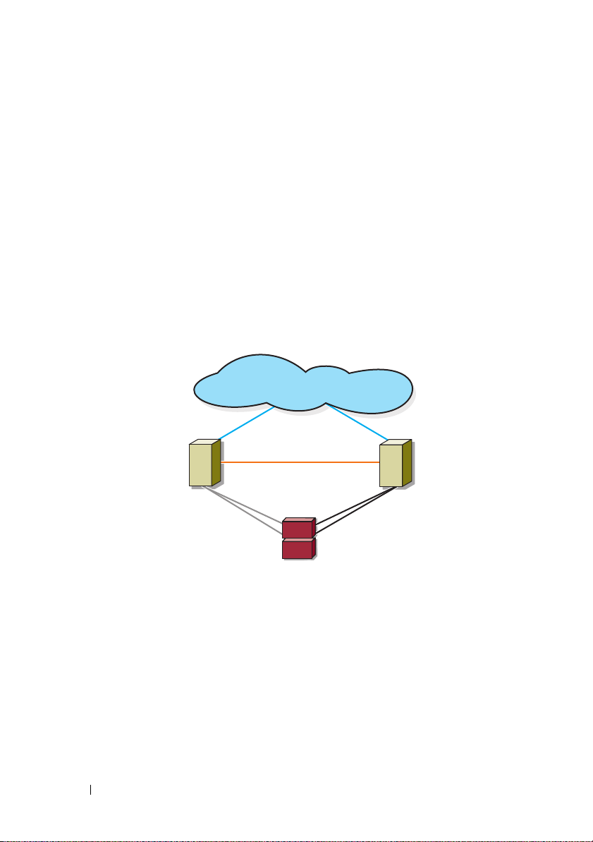
Supported Cluster Configurations
private network
public network
cluster node
iSCSI
connections
iSCSI
connections
cluster node
storage system
The following sections describe the supported cluster configurations.
Direct-Attached Cluster
In a direct-attached cluster, all the nodes of the cluster are directly attached
to a single storage system. In this configuration, the RAID controllers
(or storage processors) on the storage system are directly connected by cables
to the Gigabit or 10 Gigabit Ethernet network interface cards (NICs) in the
nodes.
Figure 1-1 shows a basic direct-attached, single-cluster configuration.
Figure 1-1. Direct-Attached, Single-Cluster Configuration
EMC PowerPath Limitations in a Direct-Attached Cluster
EMC PowerPath® provides failover capabilities, multiple path detection, and
dynamic load balancing between multiple ports on the same storage
processor. However, the direct-attached clusters supported by Dell connect to
a single port on each storage processor in the storage system. Because of the
single port limitation, PowerPath can provide only failover protection,
not load balancing, in a direct-attached configuration.
12 Introduction
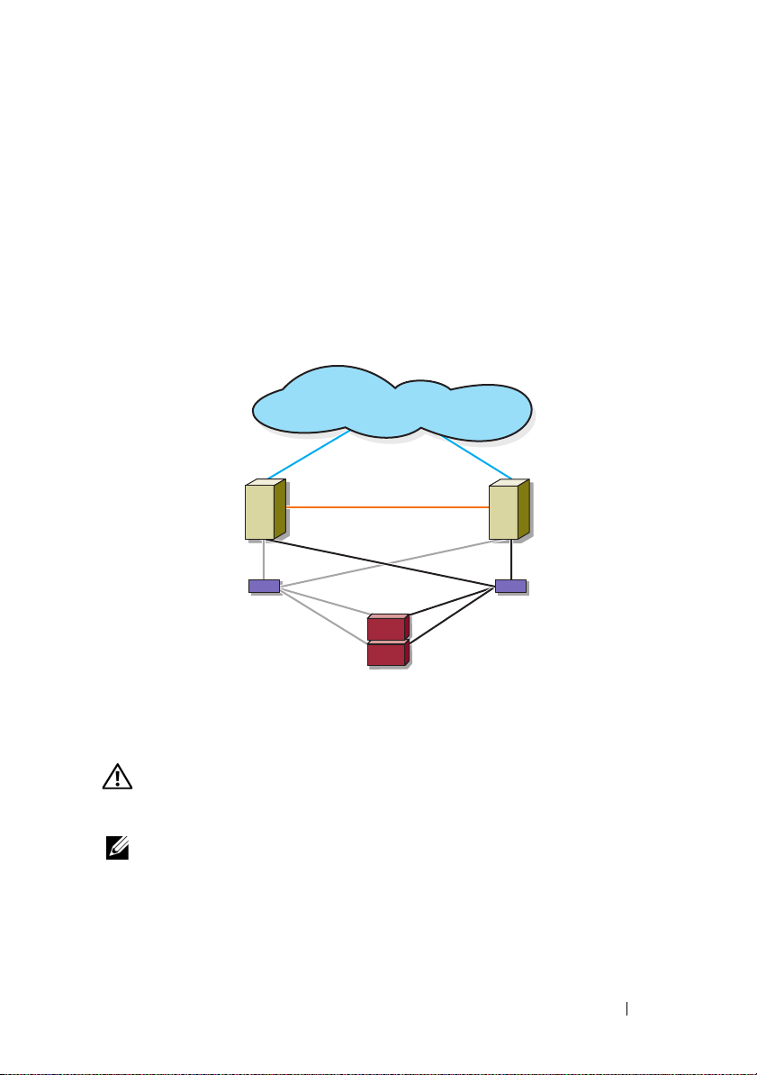
iSCSI Switch-Attached Cluster
cluster node
private network
iSCSI
connections
storage system
iSCSI switch
iSCSI switch
public network
iSCSI
connections
cluster node
In an iSCSI switch-attached cluster, all nodes are attached to a single storage
system or to multiple storage systems through redundant LANs. iSCSI
switch-attached clusters are superior to direct-attached clusters in
configuration flexibility, expandability, and performance.
Figure 1-2 shows an iSCSI Switch-Attached Cluster.
Figure 1-2. iSCSI Switch-Attached Cluster
Other Documents You May Need
• The
WARNING: The safety information that shipped with your system provides
important safety and regulatory information. Warranty information may be
included within this document or as a separate document.
NOTE: To configure Dell blade server modules in a Dell PowerEdge cluster, see the
Using Dell Blade Servers in a Dell PowerEdge High Availability Cluster document
available at support.dell.com/manuals.
Rack Installation Guide
how to install your system into a rack.
included with your rack solution describes
Introduction 13

•The
Getting Started Guide
provides an overview of initially setting
up your system.
•The
•
Dell Failover Clusters with Microsoft Windows Server 2003 Installation
and Troubleshooting Guide
cluster with the Windows Server 2003 operating systems
provides more information on deploying your
.
The Dell Failover Clusters with Microsoft Windows Server 2008
Installation and Troubleshooting Guide provides more information on
deploying your cluster with the Windows Server 2008 operating systems.
• Systems management software documentation describes the features,
requirements, installation, and basic operation of the software.
• Operating system documentation describes how to install (if necessary),
configure, and use the operating system software.
• Documentation for any components you purchased separately provides
information to configure and install those options.
• The Dell PowerVault™ tape library documentation provides information
for installing, troubleshooting, and upgrading the tape library.
• Any other documentation that came with your system or storage system.
• The EMC PowerPath documentation and Dell/EMC Storage Enclosure
User’s Guides.
• Updates are sometimes included with the system to describe changes to
the system, software, and/or documentation.
NOTE: Always read the updates first because they often supersede
information in other documents.
• Release notes or readme files may be included to provide last-minute
updates to the system or documentation, or advanced technical reference
material intended for experienced users or technicians.
14 Introduction

Cabling Your Cluster Hardware
NOTE: To configure Dell blade server modules in a Dell PowerEdge cluster, see the
Using Dell Blade Servers in a Dell PowerEdge High Availability Cluster document
available at support.dell.com/manuals.
Cabling the Mouse, Keyboard, and Monitor
When installing a cluster configuration in a rack, you must include a switch
box to connect the mouse, keyboard, and monitor to the nodes. See the
documentation included with your rack for instructions on cabling
connections of each node to the switch box.
Cabling the Power Supplies
See the documentation for each component in your cluster solution and
ensure that the specific power requirements are satisfied.
The following guidelines are recommended to protect your cluster solution
from power-related failures:
• For nodes with multiple power supplies, plug each power supply into a
separate AC circuit.
• Use uninterruptible power supplies (UPS).
• For some environments, consider having backup generators and power
from separate electrical substations.
Figure 2-1 and Figure 2-2 illustrate recommended methods for power cabling
for a cluster solution consisting of two PowerEdge systems and two storage
systems. To ensure redundancy, the primary power supplies of all the
components are grouped into one or two circuits and the redundant power
supplies are grouped into a different circuit.
Cabling Your Cluster Hardware 15
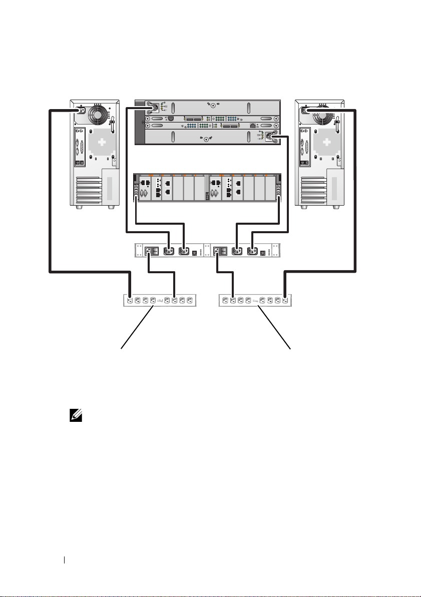
Figure 2-1. Power Cabling Example With One Power Supply in the PowerEdge Systems
redundant power
supplies on one
AC power strip (or on
one AC PDU [not shown])
NOTE: This illustration is intended only to demonstrate the power
distribution of the components.
primary power supplies
on one AC power strip
(or on one AC Power
Distribution Unit [not
shown])
01
0123
01
0123
16 Cabling Your Cluster Hardware
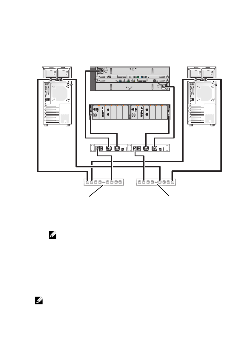
Figure 2-2. Power Cabling Example With Two Power Supplies in the PowerEdge Systems
redundant power supplies
on one AC power strip
(or on one AC PDU
[not shown])
NOTE: This illustration is intended only to demonstrate the power
distribution of the components.
primary power supplies
on one AC power strip
(or on one AC PDU
[not shown])
01
0123
01
0123
Cabling Your Cluster for Public and Private Networks
The network adapters in the cluster nodes provide at least two network
connections for each node, as described in Table 2-1.
NOTE: To configure Dell blade server modules in a Dell PowerEdge cluster, see the
Using Dell Blade Servers in a Dell PowerEdge High Availability Cluster document
available at support.dell.com/manuals.
Cabling Your Cluster Hardware 17
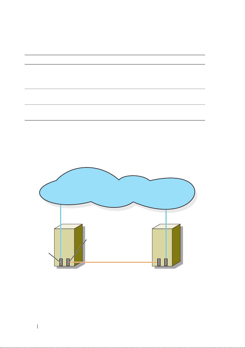
Table 2-1. Network Connections
cluster node 1
public network
public
network
adapter
private network
private network
adapter
cluster node 2
Network Connection Description
Public network All connections to the client LAN.
At least one public network must be configured for
Mixed mode for private network failover.
Private network A dedicated connection for sharing cluster health and
status information only.
iSCSI network Two direct or switched iSCSI connections from the cluster
node to the storage system.
Figure 2-3 shows an example of cabling in which dedicated network adapters
in each node are connected to each other (for the private network) and the
remaining network adapters are connected to the public network.
Figure 2-3. Example of Network Cabling Connection
18 Cabling Your Cluster Hardware

Cabling the Public Network
Any network adapter supported by a system running TCP/IP may be used to
connect to the public network segments. You can install additional network
adapters to support additional public network segments or to provide
redundancy in the event of a faulty primary network adapter or switch port.
Cabling the Private Network
The private network connection to the nodes is provided by a different
network adapter in each node. This network is used for intra-cluster
communications. Table 2-2 describes two possible private
network configurations.
Table 2-2. Private Network Hardware Components and Connections
Method Hardware Components Connection
Network switch Gigabit or 10 Gigabit
Ethernet network adapters
and switches
Point-to-Point
(two-node clusters
only)
Copper Gigabit or 10
Gigabit Ethernet network
adapters with RJ-45
connectors
Copper 10 Gigabit
Ethernet network adapters
with SFP+ connectors
Optical Gigabit or 10
Gigabit Ethernet network
adapters with LC
connectors
Depending on the hardware, connect
the CAT5e or CAT6 cables, the
multi-mode optical cables with Local
Connector (LC) connectors, or the
twin-ax cables from the network
adapters in the nodes to a switch.
Connect a standard CAT5e or CAT6
Ethernet cable between the network
adapters in both nodes.
Connect a twin-ax cable between the
network adapters in both nodes.
Connect a multi-mode optical cable
between the network adapters in
both nodes.
NOTE: For more information on the supported cable types, see your system or NIC
documentation.
Cabling Your Cluster Hardware 19

Using Dual-Port Network Adapters
You can configure your cluster to use the public network as a failover for
private network communications. If you are using dual-port network adapters,
do not configure both ports simultaneously to support both public and
private networks.
NIC Teaming
NIC teaming combines two or more NICs to provide load balancing and fault
tolerance. Your cluster supports NIC teaming, only in a public network.
NIC teaming is not supported in a private network.
Use the same brand of NICs in a team. Do not mix brands in NIC teaming.
Cabling the Storage Systems
This section provides information on cabling your cluster to a storage system
in a direct-attached configuration or to one or more storage systems in
an iSCSI switch-attached configuration.
NOTE: The illustrations in this section show examples for connecting the cluster
nodes to the Gigabit iSCSI ports of the storage system. Use optical cables and the
same cabling method to connect to the 10 Gigabit iSCSI ports of the storage system.
NOTE: The connections listed in this section are representative of one proven
method of ensuring redundancy in the connections between the cluster nodes and
the storage system. Other methods that achieve the same type of redundant
connectivity may be acceptable.
Cabling Storage for Your Direct-Attached Cluster
A direct-attached cluster configuration consists of redundant iSCSI
NIC ports cabled directly to a Dell/EMC storage system.
Figure 2-4 shows an example of a direct-attached, single cluster configuration
with redundant iSCSI ports installed in each cluster node.
20 Cabling Your Cluster Hardware
 Loading...