


Dell Embedded Box PC
5000
Installation and Operation Manual
Computer Model: Dell Embedded Box PC 5000
Regulatory Model: N01PC
Regulatory Type: N01PC001

Notes, cautions, and warnings
NOTE: A NOTE indicates important information that helps you make better
use of your computer.
CAUTION: A CAUTION indicates either potential damage to hardware or loss
of data and tells you how to avoid the problem.
WARNING: A WARNING indicates a potential for property damage, personal
injury, or death.
© 2016 Dell Inc. All rights reserved. This product is protected by U.S. and international
copyright and intellectual property laws. Dell and the Dell logo are trademarks of Dell Inc. in
the United States and/or other jurisdictions. All other marks and names mentioned herein may
be trademarks of their respective companies.
2016 - 06
Rev. A00

Contents
Overview........................................................................................5
Features......................................................................................... 6
Top view.............................................................................................................6
Bottom view.......................................................................................................8
Setting up the Embedded Box PC.......................................... 10
Mounting the Embedded Box PC on the wall................................................ 14
Setting up your operating system.......................................... 17
Ubuntu Desktop............................................................................................... 17
Reinstalling Ubuntu Desktop..................................................................... 17
Restoring Ubuntu Desktop........................................................................ 18
Restoring Ubuntu Desktop on Embedded Box PC from the
recovery USB flash drive............................................................................ 18
Creating the bootable USB flash drive...................................................... 19
Creating the recovery USB flash drive.......................................................19
Reinstalling Ubuntu Desktop..................................................................... 19
Windows OS.................................................................................................... 20
Recommended drivers and applications for Embedded Box PC............ 20
Specifications.............................................................................25
Activating your mobile broadband........................................ 29
Setting up the ZigBee Dongle.................................................30
Display options...........................................................................31
3

Connector Kits........................................................................... 32
Remote power connector...............................................................................32
12–26V DC power connector.........................................................................32
GPIO-In connector..........................................................................................33
GPIO-Out connector...................................................................................... 33
Contacting Dell..........................................................................34
4

Overview
The Embedded Box PC 5000 enables you to connect your devices (wired or
wireless) to network-enabled devices and manage them remotely in your
existing network ecosystem. It enables you to connect with devices used in
process and discrete manufacturing, fleet management, kiosks, digital
signage, surveillance, and automated retail solutions. It can be either mounted
on the wall using the Dell approved wall mount kits or placed on a flat
surface. It supports Windows 7 Professional, Windows 7 Embedded, Windows
10 Professional, Windows 10 IoT Enterprise LTSB, and Ubuntu Desktop
operating systems.
5
Features
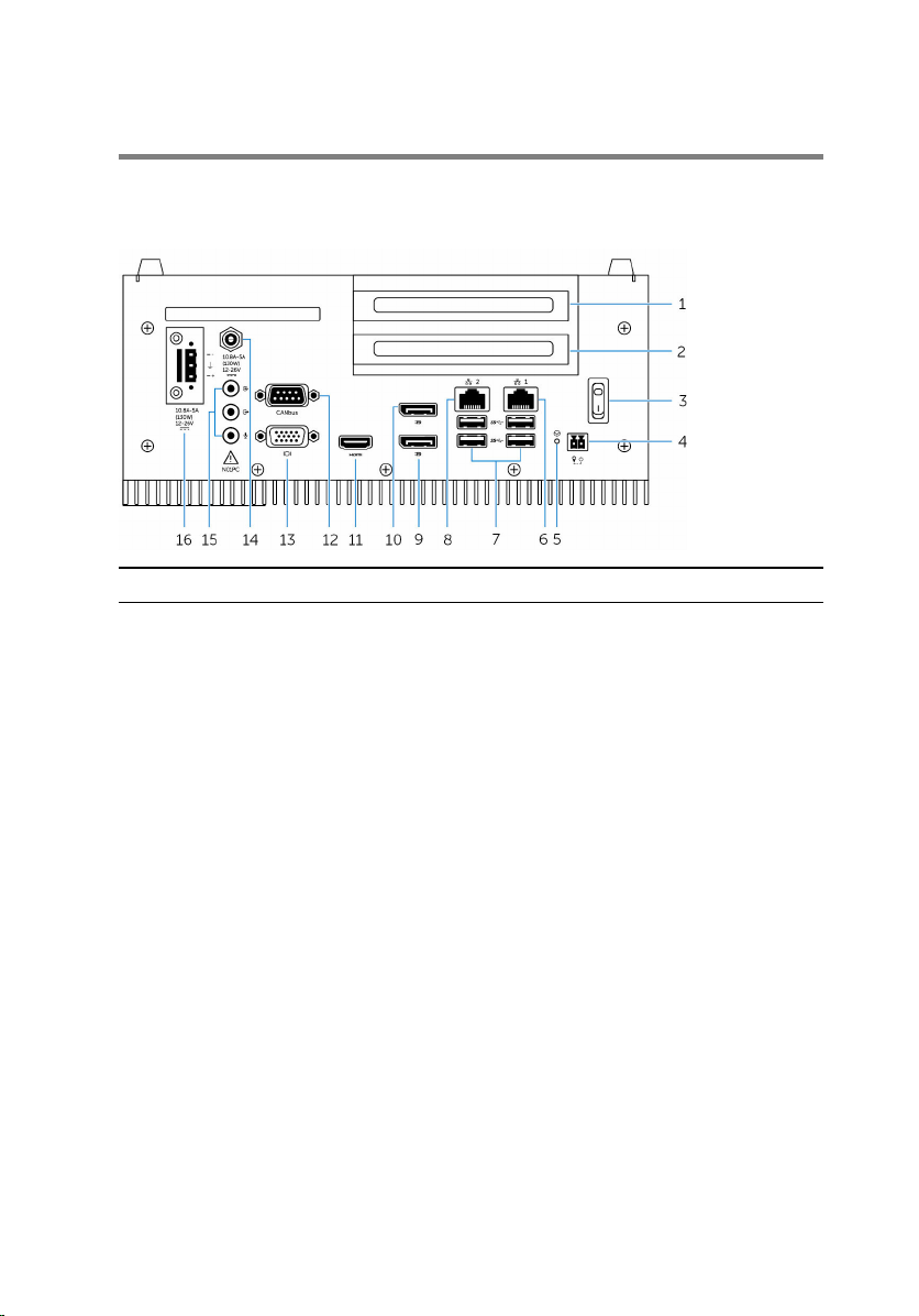
Top view
Features
1 PCI slot one
2 PCIe(x16) slot or PCI slot two 1Install a PCIe or PCI card.
3 Power switch Turn on or off the Embedded Box PC.
4 Remote power switch
5 Hard reset Using a pin, press the button located
6 Network port one Connect an Ethernet (RJ45) cable for
7 USB 3.0 ports (4) Connect USB enabled devices.
8 Network port two Connect an Ethernet (RJ45) cable for
1
2
Install a PCI card.
Install a remote power switch.
in the pin hole to restart the
Embedded Box PC.
network access. Provides data transfer
speeds up to 10/100/1000 Mbps.
Provides data transfer speeds up to 5
Gbps.
network access. Provides data transfer
speeds up to 10/100/1000 Mbps.
6

Features
9 DisplayPort two Connect a monitor or another
DisplayPort enabled device. Provides
video and audio output.
NOTE: For more information
about the display options, see
Display Options.
10 DisplayPort one Connect a monitor or another
DisplayPort enabled device. Provides
video and audio output.
NOTE: For more information
about the display options, see
Display Options.
11 HDMI port Connect a monitor or another
HDMI‑in enabled device. Provides
video and audio output.
12 CANbus port (optional) Connect to a CANbus port enabled
device or dongles.
13 VGA port Connect a monitor or another VGA
enabled device. Provides video output.
14 12-26V DC power port (barrel
connector)
Connect a 12-26V DC power cable for
supplying power to your Embedded
Box PC.
15 Audio ports (3) Connect a speaker, a headphone, a
microphone, or a headset (headphone
and microphone combo).
NOTE: Connect the headset to
the Line Out port.
16 +12-26V DC power
connector
Connect a 12-26V DC power
connector for supplying power to your
Embedded Box PC.
1 Slot one and two supports 20 W to 25 W (12 V/2 A) cards and 10 W thermal capability.
2 Connections made to these ports must be an SELV circuit and the wire (26 AWG - 18 AWG) must
have Double Insulation (DI) or Reinforced Insulation (RI) to protect it from all hazardous voltages.
Torque the screws at 2.88 kg-cm (2.5 lb-in) to secure the wire to the connector.
7
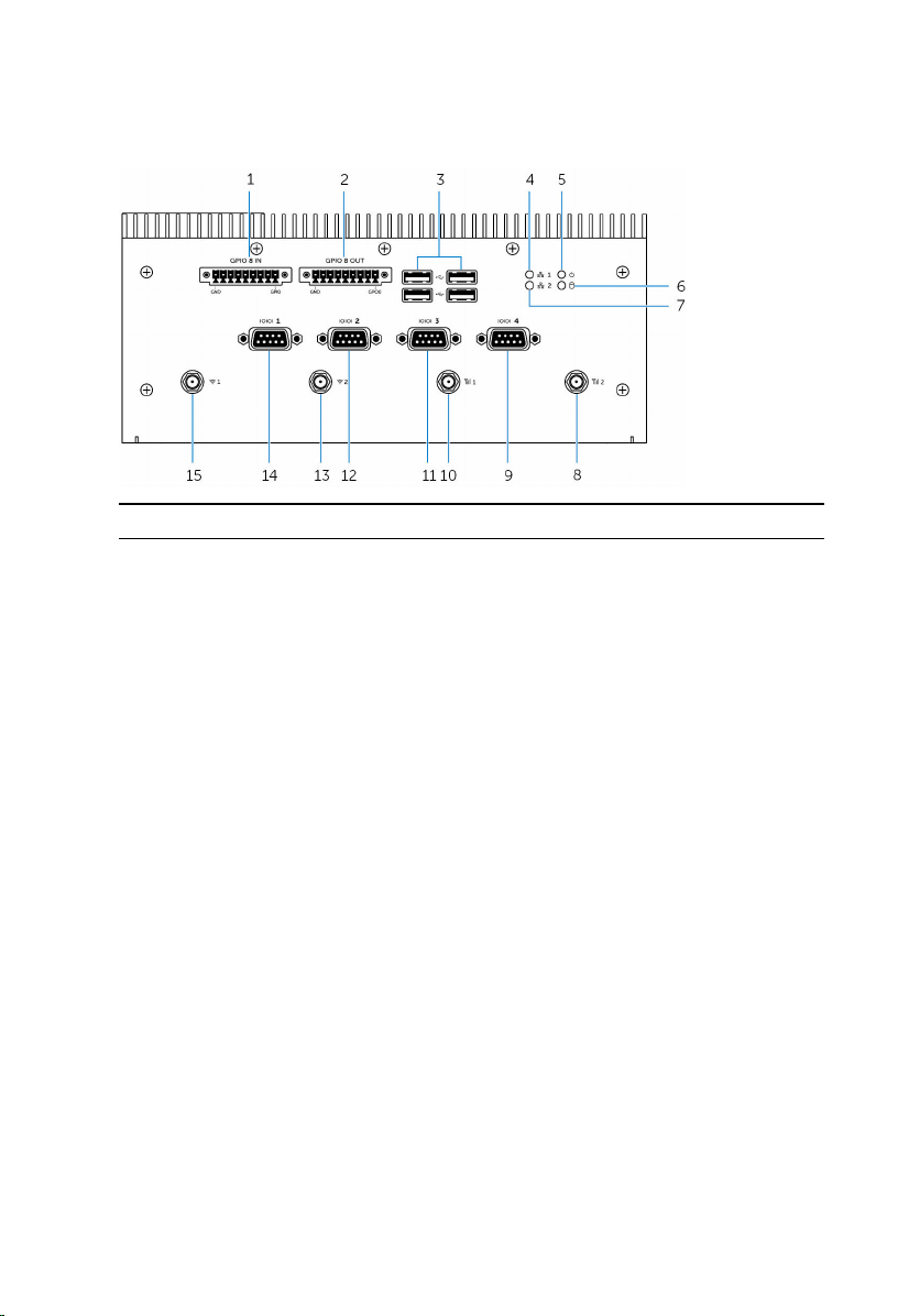
Bottom view
Features
1 GPIO-In 8-pin port
2 GPIO-Out 8-pin port
3 USB 2.0 ports (4) Connect USB enabled devices.
4 Network status light one Indicates the network activity of the
5 Power status light Indicates the power‑state of the
6 Hard-drive activity light Turns on when the Embedded Box PC
7 Network status light two Indicates the network activity of the
8 Mobile broadband antenna
port two
9 RS232/RS422/RS485 port four
(configurable in the BIOS)
1, 2, 4
2, 3, 4
Connect to a GPIO-out enabled
device or dongles.
Connect to a GPIO-in enabled device
or dongles.
Provides data transfer speeds up to
480 Mbps.
network port one.
Embedded Box PC.
reads from or writes to the internal
storage device.
network port two.
Connect a mobile broadband antenna
to increase the range and strength of
the mobile broadband signals.
Connect a RS232/RS422/RS485 cable
to the Embedded Box PC.
8

Features
10 Mobile broadband antenna
port one
Connect a mobile broadband antenna
to increase the range and strength of
the mobile broadband signals.
11 RS232/RS422/RS485 port
three (configurable in the
Connect a RS232/RS422/RS485 cable
to the Embedded Box PC.
BIOS)
12 RS232/RS422/RS485 port two
(configurable in the BIOS)
Connect a RS232/RS422/RS485 cable
to the Embedded Box PC.
13 Wireless antenna port two Connect a wireless antenna to
increase the range and strength of the
wireless signals.
14 RS232/RS422/RS485 port one
(configurable in the BIOS)
Connect a RS232/RS422/RS485 cable
to the Embedded Box PC.
15 Wireless antenna port one Connect a wireless antenna to
increase the range and strength of the
wireless signals.
1 GPIO-In port has a total of 9 pins, except GND pin, the other 8 pins are GPI0 to GPI7.
2 Connections made to these ports must be an SELV circuit and the wire (26 AWG - 18 AWG) must
have Double Insulation (DI) or Reinforced Insulation (RI) to protect it from all hazardous voltages.
Torque the screws at 2.88 kg-cm (2.5 lb-in) to secure the wire to the connector.
3 GPIO-Out port has a total of 9 pins, except GND pin, the other 8 pins are GPO0 to GPO7.
4 Connections made to GPIO IN/OUT must be SELV Circuits (30 Vmax) and must be Double/
Reinforced Insulation (DI) (RI) from all hazardous voltages.
9

Setting up the Embedded Box PC
WARNING: During the installation of the Embedded Box PC, the
responsible party or integrator must use the power adapter provided
with the Embedded Box PC, or connect to a 12-26 VDC separate
power source already present as part of the clients installation. Always
ensure that the available power source matches the required input
power of the Embedded Box PC. Check the input power markings next
to power connector(s) before making connections.
WARNING: Before you begin any of the procedures in this section,
read the safety information that shipped with your Embedded Box PC.
For additional best practices information, go to www.dell.com/
regulatory_compliance.
WARNING: To ensure that the protection provided by the Embedded
Box PC is not impaired, do not use or install the Embedded Box PC in
any manner other than what is specified in this manual.
WARNING: To provide additional power connections to the main
network, use cables appropriate for the load currents such as, 3-core
cable rated 15 A at 90°C (194°F) minimum, which conform to either
IEC 60227 or IEC 60245. The Embedded Box PC accepts cables from
0.8 mm to 2.5 mm (18 AWG to 14 AWG).
WARNING: The symbol indicates hot surface or adjacent hot
surface that can obtain temperature during normal use that can cause
a burn. Allow equipment to cool off or use protective gloves when
handling to reduce risk of a burn.
WARNING: This product is designed for specific applications and must
be installed by qualified personnel with RF and regulatory related
knowledge. The general user must not attempt to install or change the
setting.
WARNING: Before installation, the two power inputs (Terminal Block
or Power Jack) must be protected by 20 A fuses or circuit-breakers,
which are over current protection devices in front of the Embedded
Box PC.
10

WARNING: The product shall be installed at a location where the
radiating antenna is kept 20 cm away from nearby persons in its
normal operating condition to meet regulatory RF exposure
requirements.
WARNING: Use only the antenna(s), which are approved by Dell.
WARNING: Connect a certified SELV power to either Phoenix
connector or the Barrel connector only. The connection of two power
sources may damage equipment and present risk of fire.
WARNING: If your equipment or accessories are provided with a
detachable main supply cord set and has to be replaced, ensure that
the replacement cord set has an adequate voltage, current, and
temperature rating for the country where the equipment is installed.
The cord set must comply to the local safety code, regulations, and
law.
1 Install the Embedded Box PC on a vertical surface like a wall using wall-
mount brackets or in a panel box.
11

2 Connect to your network in one of the following methods:
– Connect the network cable.
– Install the wireless antenna (WLAN 1 and WLAN 2) to enable the
wireless connection.
– Install the mobile broadband antenna (WWAN 1 and WWAN 2) to
enable the mobile broadband connection.
NOTE: For more information on connecting the wireless antenna to
Dell Embedded Box PC, see the documentation that is shipped with
the wireless antenna.
NOTE: For more information about installing the WWAN card in the
Embedded Box PC, see the Embedded Box PC Service Manual at
www.dell.com/support.
NOTE: The peripherals such as wireless antenna, keyboard, and
12
mouse are sold separately.

3 Connect devices using the I/O ports on your Embedded Box PC.
4 Connect the Embedded Box PC to the power source in one of the
following methods:
– Connect the power adapter and tighten the sleeves on the adapter
pin to secure it to the Embedded Box PC.
– Connect the power terminal block to the adapter port and torque the
screws at 5.07 kilograms-centimeter (4.4 pounds-inch) to secure it to
the Embedded Box PC.
5 Turn on the Embedded Box PC and complete the operating system
setup.
13

Mounting the Embedded Box PC on the wall
Mount the Embedded Box PC on a wall by using the mounting brackets. The
brackets secure the Embedded Box PC to the wall.
NOTE: The Embedded Box PC is shipped with only those screws that are
required for securing the two mounting brackets to the back of the
Embedded Box PC.
1 Secure the two mounting brackets to the back of the Embedded Box PC
by using eight M3x8 screws.
NOTE: Torque the screws at 3 to 3.4 kilograms-centimeter (2.6 to
3.0 pounds-inch).
2 Drill four holes in the wall that correspond to the holes on the mounting
bracket.
14

3 Place the Embedded Box PC against the wall and align the holes on the
mounting brackets with the holes on the wall.
15

4 Secure the Embedded Box PC to the wall.
NOTE: Torque the screws (M4x6) at 5 to 5.4 kilograms-centimeter
(4.3 to 4.7 pounds-inch).
16

Setting up your operating system
The Embedded Box PC is shipped with one of the following operating
systems:
• Windows 7 Professional
• Windows 7 Embedded
• Windows 10 Professional
• Windows 10 IoT Enterprise LTSB
• Ubuntu Desktop
NOTE: For more information about Windows operating systems, see
msdn.microsoft.com.
NOTE: For more information about Ubuntu Desktop operating system,
see www.ubuntu.com/desktop.
Ubuntu Desktop
Reinstalling Ubuntu Desktop
Before reinstalling Ubuntu Desktop, ensure the following:
• Connect a keyboard, mouse, and monitor to the Embedded Box PC, or
connect to the Embedded Box PC through a KVM session, Dell Wyse
Cloud Client Manager (CCM), or Dell Command | Monitor (DCM).
• Create a bootable USB flash drive.
NOTE: For more information about using the CCM, see the CCM
documentation available at www.cloudclientmanager.com.
NOTE: For more information about using the DCM, see the DCM
documentation available at
NOTE: It is recommended to create a recovery USB flash drive when
installing Ubuntu Desktop for the first time.
www.dell.com/clientsystemsmanagement.
17

Follow these steps to reinstall Ubuntu Desktop:
1 Insert the bootable Ubuntu Desktop USB flash drive.
2 Turn on the Embedded Box PC.
3 Press F12 to access the boot menu.
4 Enable UEFI boot mode in the System Setup and boot from the Ubuntu
Desktop USB flash drive.
5 Select Dell recovery to start the Ubuntu Desktop installation.
6 Select the drive to install the Ubuntu Desktop operating system.
7 After the installation is complete, restart the Embedded Box PC.
8 Follow the instructions on the screen to configure the Language, License
Agreement, Location, Keyboard Layout, and User name/password
settings.
The Embedded Box PC restarts to boot Ubuntu Desktop successfully.
Restoring Ubuntu Desktop
You can restore Ubuntu Desktop on the Embedded Box PC to a new
condition if you encounter any of the following situations:
• When you are unable to start Ubuntu Desktop
• When Ubuntu Desktop operating system is damaged
Before restoring, a recovery USB flash drive with the backup image must be
created.
Restoring Ubuntu Desktop on Embedded Box PC from the recovery USB flash drive
1 Insert the recovery USB flash drive to the Embedded Box PC.
2 Turn on the Embedded Box PC.
3 Press F12 to access the boot menu.
4 Enable UEFI boot mode in the System Setup and boot from the Ubuntu
Desktop USB flash drive.
5 Select Dell recovery to start Ubuntu Desktop recovery.
6 Select the disk to install the Ubuntu Desktop operating system.
7 After the installation is complete, restart the Embedded Box PC.
8 Follow the instructions on the screen to complete the Language, License
Agreement, Location, Keyboard Layout, and User name/Password
settings.
The Embedded Box PC restarts to boot Ubuntu Desktop successfully.
18

Creating the bootable USB flash drive
1 Download the Ubuntu Desktop ISO image from www.ubuntu.com/
download/desktop.
2 Follow the instructions provided at www.ubuntu.com/download/
desktop/create-a-usb-stick-on-windows.
3 Reinstall the Ubuntu Desktop operating system from the bootable USB
flash drive.
Creating the recovery USB flash drive
Create a recovery disk when installing Ubuntu Desktop for the first time.
1 Turn on the Embedded Box PC.
2 Follow the instructions on the screen when you start the Embedded Box
PC for the first time.
3 Select Language and click Continue.
4 Agree the license agreement and click Continue.
5 Select a location and click Continue.
6 Select the keyboard layout and click Continue.
7 Enter the user name and password, and then click Continue.
8 Insert a USB flash drive with 2 GB or more space to create the recovery
USB flash drive, and then click Continue.
9 To create a startup disk, select USB stick user plugged, and the click
Make Startup Disk.
The recovery USB flash drive is created.
Reinstalling Ubuntu Desktop
Before reinstalling Ubuntu Desktop, ensure the following:
• Connect a keyboard, mouse, and monitor to the Embedded Box PC, or
connect to the Embedded Box PC through a KVM session, Dell Wyse
Cloud Client Manager (CCM), or Dell Command | Monitor (DCM).
• Create a bootable USB flash drive.
NOTE: For more information about using the CCM, see the CCM
documentation available at www.cloudclientmanager.com.
NOTE: For more information about using the DCM, see the DCM
documentation available at
www.dell.com/clientsystemsmanagement.
19

NOTE: It is recommended to create a recovery USB flash drive when
installing Ubuntu Desktop for the first time.
Follow these steps to reinstall Ubuntu Desktop:
1 Insert the bootable Ubuntu Desktop USB flash drive.
2 Turn on the Embedded Box PC.
3 Press F12 to access the boot menu.
4 Enable UEFI boot mode in the System Setup and boot from the Ubuntu
Desktop USB flash drive.
5 Select Dell recovery to start the Ubuntu Desktop installation.
6 Select the drive to install the Ubuntu Desktop operating system.
7 After the installation is complete, restart the Embedded Box PC.
8 Follow the instructions on the screen to configure the Language, License
Agreement, Location, Keyboard Layout, and User name/password
settings.
The Embedded Box PC restarts to boot Ubuntu Desktop successfully.
Windows OS
Recommended drivers and applications for Embedded Box PC
Dell recommends installing the drivers and applications required for the
Embedded Box PC from www.dell.com/support in the following sequence:
1 Intel Mobile Chipset Software Installation Utility
2 Critical Microsoft Quick Fix Engineering (QFE)
3 Intel Rapid Storage Technology
4 Graphics
5 Intel Management Technology
6 Audio
7 Integrated wired Network Adapter
8 Wireless Local Network Adapters and Bluetooth
9 USB 3.0
10 ZigBee
11 CANbus
20

Intel Mobile Chipset Software Installation Utility
1 Go to www.dell.com/support.
2 Click Product support, enter the Service Tag of the Embedded Box PC,
and then click Submit.
NOTE: If you do not have the Service Tag, use the auto-detect
feature or manually browse for the Embedded Box PC model.
3 Click Drivers & downloads → Find it myself.
4 Scroll down the page and expand Chipset.
5 Click Download to download the Intel Mobile Chipset Software
Installation Utility.
6 After the download is complete, navigate to the folder where you saved
the chipset driver file.
7 Double-click the chipset driver file icon and follow the instructions on
the screen.
Critical Microsoft QFEs
Dell recommends installing all the latest available fixes specific to Embedded
Box PC through Windows Update or from www.microsoft.com.
Intel Rapid Storage Technology
The Intel Rapid Storage Technology (IRST) driver must be installed in AHCI or
RAID mode. The Intel IRST application must also be installed.
The SATA operation modes are configured in the BIOS. If the SATA mode is
configured in AHCI or RAID mode, the IRST driver must be installed during the
initial operating system installation stages. The IRST driver is only available
from Dell.
1 Go to www.dell.com/support.
2 Click Product support, enter the Service Tag of the Embedded Box PC,
and then click Submit.
NOTE: If you do not have the Service Tag, use the auto-detect
feature or manually browse for the Embedded Box PC model.
3 Click Drivers & downloads → Find it myself.
4 Scroll down the page and expand Serial ATA.
5 Click Download to download the Dell IRST driver file.
6 After the download is complete, navigate to the folder where you saved
the Dell IRST driver file.
7 Double-click the Dell IRSTdriver file icon and follow the instructions on
the screen.
21

Graphics
1 Go to www.dell.com/support.
2 Click Product support, enter the Service Tag of the Embedded Box PC,
and then click Submit.
NOTE: If you do not have the Service Tag, use the auto-detect
feature or manually browse for the Embedded Box PC model.
3 Click Drivers & downloads → Find it myself.
4 Scroll down the page and expand Video.
5 Click Download to download the graphics driver file.
6 After the download is complete, navigate to the folder where you saved
the graphics driver file.
7 Double-click the graphics driver file icon and follow the instructions on
the screen.
Intel Management Technology
1 Go to www.dell.com/support.
2 Click Product support, enter the Service Tag of the Embedded Box PC,
and then click Submit.
NOTE: If you do not have the Service Tag, use the auto-detect
feature or manually browse for the Embedded Box PC model.
3 Click Drivers & downloads → Find it myself.
4 Scroll down the page and expand Chipset.
5 Click Download to download the Intel Management Engine Component
Installer and Intel Serial I/O driver.
6 After the download is complete, navigate to the folder where you saved
the driver files.
7 Double-click the driver file icons and follow the instructions on the
screen.
Audio
1 Go to www.dell.com/support.
2 Click Product support, enter the Service Tag of the Embedded Box PC,
and then click Submit.
NOTE: If you do not have the Service Tag, use the auto-detect
feature or manually browse for the Embedded Box PC model.
3 Click Drivers & downloads → Find it myself.
4 Scroll down the page and expand Audio.
5 Click Download to download the HD Audio driver.
22

6 After the download is complete, navigate to the folder where you saved
the HD Audio driver file.
7 Double-click the HD Audio driver file icon and follow the instructions on
the screen.
Integrated wired Network Adapter
1 Go to www.dell.com/support.
2 Click Product support, enter the Service Tag of the Embedded Box PC,
and then click Submit.
NOTE: If you do not have the Service Tag, use the auto-detect
feature or manually browse for the Embedded Box PC model.
3 Click Drivers & downloads → Find it myself.
4 Scroll down the page and expand Network.
5 Click Download to download the LAN driver.
6 After the download is complete, navigate to the folder where you saved
the LAN driver file.
7 Double-click the LAN driver file icon and follow the instructions on the
screen.
NOTE: Enable the Windows Update and connect to Internet after
installing the Integrated Wired Network Controller driver.
Wireless Local Network Adapters and Bluetooth
1 Go to www.dell.com/support.
2 Click Product support, enter the Service Tag of the Embedded Box PC,
and then click Submit.
NOTE: If you do not have the Service Tag, use the auto-detect
feature or manually browse for the Embedded Box PC model.
3 Click Drivers & downloads → Find it myself.
4 Scroll down the page and expand Network.
5 Click Download to download the Wireless LAN and Bluetooth device
drivers.
6 After the download is complete, navigate to the folder where you saved
the driver files.
7 Double-click the driver file icons and follow the instructions on the
screen.
USB 3.0
1 Go to www.dell.com/support.
2 Click Product support, enter the Service Tag of the Embedded Box PC,
and then click Submit.
23

NOTE: If you do not have the Service Tag, use the auto-detect
feature or manually browse for the Embedded Box PC model.
3 Click Drivers & downloads → Find it myself.
4 Scroll down the page and expand Chipset.
5 Click Download to download the USB 3.0 driver.
6 After the download is complete, navigate to the folder where you saved
the USB 3.0 driver file.
7 Double-click the USB 3.0 driver file icon and follow the instructions on
the screen.
ZigBee
1 Go to www.dell.com/support.
2 Click Product support, enter the Service Tag of the Embedded Box PC,
and then click Submit.
NOTE: If you do not have the Service Tag, use the auto-detect
feature or manually browse for the Embedded Box PC model.
3 Click Drivers & downloads → Find it myself.
4 Scroll down the page and expand Network.
5 Click Download to download the ZigBee 3.0 driver.
6 After the download is complete, navigate to the folder where you saved
the ZigBee 3.0 driver file.
7 Double-click the ZigBee 3.0 driver file icon and follow the instructions
on the screen.
CANbus
1 Go to www.dell.com/support.
2 Click Product support, enter the Service Tag of the Embedded Box PC,
and then click Submit.
NOTE: If you do not have the Service Tag, use the auto-detect
feature or manually browse for the Embedded Box PC model.
3 Click Drivers & downloads → Find it myself.
4 Scroll down the page and expand Chipset.
5 Click Download to download the CANbus driver.
6 After the download is complete, navigate to the folder where you saved
the CANbus driver file.
7 Double-click the CANbus driver file icon and follow the instructions on
the screen.
24

Specifications
Dimension and weight
Width 246 mm (9.69 in)
Depth 270 mm (10.63 in)
Height 107.20 mm (4.22 in)
Weight 5.80 kg (12.80 lb)
System information
Model number Dell Embedded Box PC 5000
Processor
Operating systems supported
Storage
Storage devices supported
• Intel Celeron G3900E
• Intel Core i3-6100E
• Intel Core i5-6440EQ
• Intel Core i7-6820EQ
NOTE: Depending on workload,
Intel 4th generation Core i7
configurations could throttle in
operating environments above
35°C (95°F).
• Windows 10 Professional
• Windows 10 IoT Enterprise LTSB
• Windows 7 Professional
• Windows 7 Embedded
• Ubuntu Desktop
• Two 2.5-inch SATA hard drive
• Two M.2 solid-state drive with
interposer
• One 2.5-inch SATA hard drive +
one M.2 solid-state drive with
interposer
25

Memory
Slots 2 DIMM slots (maximum 8 GB per
slot)
Type DDR4
Speed 2133 MHz
Configurations supported
Ports and connectors
Audio/video
Network
I/O port
• 4 GB
• 8 GB
• 16 GB
• One HDMI port
• One VGA port
• Two DisplayPort
• One line-in port
• One line-out port
• One microphone port
NOTE: For more information
about the display options, see
Display Options.
• Two RJ45 ports
• Two wireless ports
• Two mobile broadband antenna
ports
• One CANbus port (optional)
• Four RS232/RS422/RS485 ports
• GPIO 16-bit
USB
26
• Four USB 3.0 ports
• Four USB 2.0 ports

Communications
WiFi Dual-band 802.11b/g/n/ac
Bluetooth Bluetooth 4.1 LE
Power requirements
Phoenix connector input voltage/
current
Power input voltage/current 12 VDC/10.80 A-26 VDC/5 A
WARNING: Connect a certified SELV power to either Phoenix
connector or the Barrel connector only. The connection of two
power sources may damage equipment and present risk of fire.
RTC coin-cell battery (lithium ion)
Type CR-2032H BR-2032 Others
Manufacturer
Maximum abnormal charging rate:
Voltage 3 V 3 V 3 V
Current 10 mA 10 mA 10 mA
Standard UL1642 UL1642 UL1642
Approval UL (MH12568) UL (MH12210) UL (MHxxxxx)
Environmental requirements
• Hitachi Ltd.
• Maxell Ltd.
12 VDC/10.80 A-26 VDC/5 A
Panasonic Corp. Varies depending
on the battery type
Temperature range:
Operating: Hard drive 0°C to 40°C (32°F to 104°F)
Operating: Solid-state drive 0°C to 50°C (32°F to 122°F)
Non-operating –40°C to 65°C (–40°F to 149°F)
Relative humidity (maximum):
Operating 10% to 90% (non-condensing)
Non-operating 5% to 95% (non-condensing)
27

Environmental requirements
Altitude (maximum, unpressurized):
Operating –15.20 m to 5000 m (–50 ft to
16,404 ft)
Storage –15.20 m to 10,668 m (Sea level to
35,000 ft)
IP level IP 30
28

Activating your mobile broadband
NOTE: For more information about installing the SIM card, see the
Embedded Box PC Service Manual at www.dell.com/support.
1 Turn on the Embedded Box PC.
2 Follow these steps to connect to the mobile broadband network:
NOTE: To activate your mobile broadband service, please contact
the service provider with the following information:
Windows OS
a From the task bar select the Network icon and then select Cellular.
The Cellular page is displayed.
b Select your Mobile Broadband Carrier to expand the options.
c Select Advanced Options.
The options are displayed.
d Make a note of the International Mobile Equipment Identity (IMEI)
and the Integrated Circuit Card Identifier (ICCID).
Ubuntu OS
Open the Terminal window.
a Go to super user mode by entering:$sudo su -
b Configure the Mobile Broadband connection profile:
#nmcli con add type gsm ifname ttyACM3 con-name
<connection name>
<password>
c Connect to the mobile network: #nmcli con up <connection
name>
To disconnect from the mobile network: #nmcli con down
<connection name>.
apn <apn> user <user name> password
29

Setting up the ZigBee Dongle
1 Shut down the Embedded Box PC.
2 Connect the ZigBee dongle to any external USB port on the Embedded
Box PC.
3 Turn on the Embedded Box PC and complete the setup.
NOTE: For ZigBee development information, see the SiLabs
developer website at www.silabs.com or contact the network
system’s application provider.
30

Display options
Embedded Box PC consists of the following video connectors:
• VGA
• HDMI
• DisplayPort 1 (DP1)
• DisplayPort 2 (DP2)
The Embedded Box PC supports up to three simultaneous connections. The
enabled ports are:
• HDMI, DP1, and VGA (default)
• HDMI, DP1, and DP2
The video output is always supported on HDMI and DP1. You can switch the
display output between VGA port and DP2 port in the BIOS.
NOTE: The video output availability depends on the operating system
support and configuration.
31

Connector Kits
Remote power connector
Use the remote power connector to install the remote power switch.
12–26V DC power connector
Use a 12-26V DC power connector for supplying power to your Embedded
Box PC.
32

GPIO-In connector
Use the GPIO-In connector for connecting the GPIO-out enabled device or
dongles.
GPIO-Out connector
Use the GPIO-Out connector for connecting the GPIO-in enabled device or
dongles.
33

Contacting Dell
To contact Dell for sales, technical assistance, or customer service issues:
1 Go to www.dell.com/contactdell.
2 Verify your country or region in the drop-down list at the bottom of the
page.
3 Select the appropriate service or support link based on your requirement
or choose the method of contacting Dell that is convenient for you.
Dell provides several online and telephone-based support and service
options. Availability varies by country and product, and some services
may not be available in your area.
NOTE: If you do not have an active internet connection, you can
find contact information on your purchase invoice, packing slip, bill,
or Dell product catalog.
34
 Loading...